Form No. 3464-976 Rev A
E-Z V ac
™
Complete T win Bagger
T imeCutter
®
HD and T itan
®
Riding Mower
Model No. 79345 —Serial No. 415204500 and Up
Model No. 79346 —Serial No. 415186600 and Up
Register at www .T oro.com.
Original Instructions (EN)
*3464-976*
W ARNING
CALIFORNIA
Proposition 65 W arning
Use of this product may cause exposure
to chemicals known to the State of
California to cause cancer , birth defects,
or other reproductive harm.
Introduction
Read this information carefully to learn how to operate
and maintain your product properly and to avoid
injury and product damage. Y ou are responsible for
operating the product properly and safely .
V isit www .T oro.com for product safety and operation
training materials, accessory information, help nding
a dealer , or to register your product.
Whenever you need service, genuine T oro parts, or
additional information, contact an Authorized Service
Dealer or T oro Customer Service and have the model
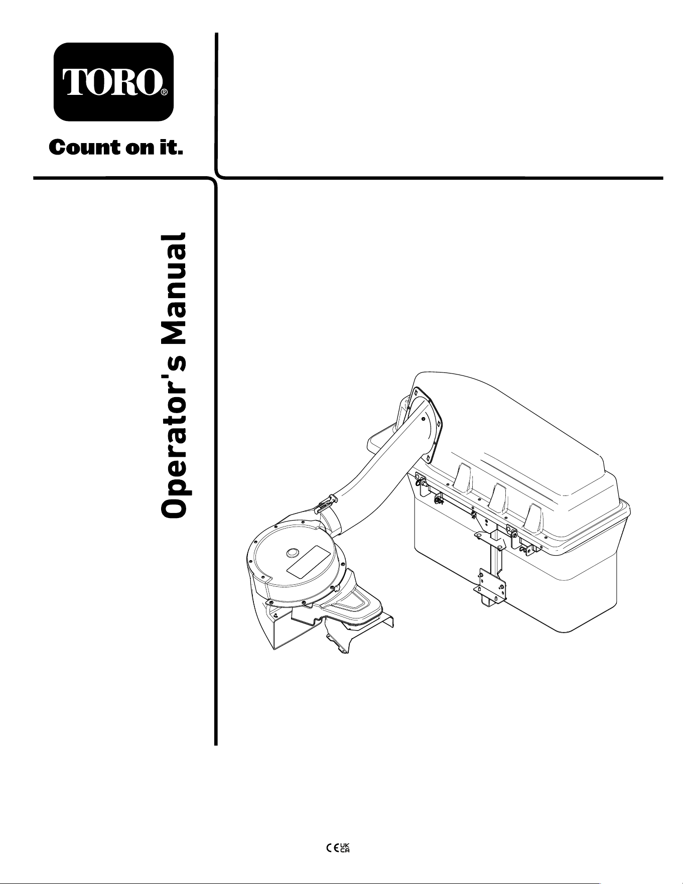
and serial numbers of your product ready . Figure 1
identies the location of the model and serial numbers
on the product. W rite the numbers in the space
provided.
g005673
Figure 1
1. Model and serial number location
Model No.
Serial No.
This manual uses 2 words to highlight information.
Important calls attention to special mechanical
information and Note emphasizes general information
worthy of special attention.
The safety-alert symbol ( Figure 2 ) appears both in
this manual and on the machine to identify important
safety messages that you must follow to avoid
accidents. This symbol will appear with the word
Danger , W arning , or Caution .
• Danger indicates an imminently hazardous
situation which, if not avoided, will result in death
or serious injury .
• W arning indicates a potentially hazardous
situation which, if not avoided, could result in
death or serious injury .
• Caution indicates a potentially hazardous situation
which, if not avoided, may result in minor or
moderate injury .
sa-black
Figure 2
1. Safety-alert symbol
Contents
Safety . . . . . . . . . . . . . . . . . . . . . . . . . . . . . . . . . . . . . . . . . . . . . . . . . . . . . . . . . . . . . . . . . . . . . . . 3
T owing Safety . . . . . . . . . . . . . . . . . . . . . . . . . . . . . . . . . . . . . . . . . . . . . . . . . . . . . 4
Safety and Instructional Decals . . . . . . . . . . . . . . . . . . . . . . . . . . 5
Setup . . . . . . . . . . . . . . . . . . . . . . . . . . . . . . . . . . . . . . . . . . . . . . . . . . . . . . . . . . . . . . . . . . . . . . . . 6
1 Preparing the Machine . . . . . . . . . . . . . . . . . . . . . . . . . . . . . . . . . . . . . 7
2 Installing the W eight . . . . . . . . . . . . . . . . . . . . . . . . . . . . . . . . . . . . . . . . . 7
3 Removing the Grass Deector and Belt
Cover . . . . . . . . . . . . . . . . . . . . . . . . . . . . . . . . . . . . . . . . . . . . . . . . . . . . . . . . . . . . . . 8
4 Installing the Baf e and Blower
Support . . . . . . . . . . . . . . . . . . . . . . . . . . . . . . . . . . . . . . . . . . . . . . . . . . . . . . . . . . . 9
5 Installing the Pulley Assembly , Belt Cover ,
and Shoulder Bolt . . . . . . . . . . . . . . . . . . . . . . . . . . . . . . . . . . . . . . . . . . . 1 1
6 Installing the Attachment Mount . . . . . . . . . . . . . . . . . . . . . . 1 1
7 Installing the Latch Rod . . . . . . . . . . . . . . . . . . . . . . . . . . . . . . . . . . 13
8 Assembling the Bagger T op . . . . . . . . . . . . . . . . . . . . . . . . . . . 14
9 Assembling the Grass Bags . . . . . . . . . . . . . . . . . . . . . . . . . . . 15
10 Installing the Bagger T op . . . . . . . . . . . . . . . . . . . . . . . . . . . . . . 15
1 1 Installing the Blower Assembly . . . . . . . . . . . . . . . . . . . . . 16
12 Installing the Blower Belt and Powered
Bagger Cover . . . . . . . . . . . . . . . . . . . . . . . . . . . . . . . . . . . . . . . . . . . . . . . . 17
13 Installing the Discharge T ubes . . . . . . . . . . . . . . . . . . . . . 18
Operation . . . . . . . . . . . . . . . . . . . . . . . . . . . . . . . . . . . . . . . . . . . . . . . . . . . . . . . . . . . . . . . . 21
Emptying the Grass Bags . . . . . . . . . . . . . . . . . . . . . . . . . . . . . . . . . 21
Clearing Obstructions from the Bagger . . . . . . . . . . . . . 22
Removing the Bagger . . . . . . . . . . . . . . . . . . . . . . . . . . . . . . . . . . . . . . . 22
Operating T ips . . . . . . . . . . . . . . . . . . . . . . . . . . . . . . . . . . . . . . . . . . . . . . . . . 23
Maintenance . . . . . . . . . . . . . . . . . . . . . . . . . . . . . . . . . . . . . . . . . . . . . . . . . . . . . . . . . . . 24
Recommended Maintenance Schedule(s) . . . . . . . . . . . 24
© 2023—The T oro® Company
81 1 1 L yndale A venue South
Bloomington, MN 55420
2
Contact us at www .T oro.com.
Printed in the USA
All Rights Reserved

Preparing for Maintenance . . . . . . . . . . . . . . . . . . . . . . . . . . . . . . . 24
Cleaning the Hood Screen . . . . . . . . . . . . . . . . . . . . . . . . . . . . . . . . 24
Cleaning the Bagger and Bags . . . . . . . . . . . . . . . . . . . . . . . . . 25
Inspecting the Blower Belt . . . . . . . . . . . . . . . . . . . . . . . . . . . . . . . . 25
Replacing the Blower Belt . . . . . . . . . . . . . . . . . . . . . . . . . . . . . . . . . 25
Inspecting the Bagger . . . . . . . . . . . . . . . . . . . . . . . . . . . . . . . . . . . . . . . 25
Inspecting the Mower Blades . . . . . . . . . . . . . . . . . . . . . . . . . . . . 25
Storage . . . . . . . . . . . . . . . . . . . . . . . . . . . . . . . . . . . . . . . . . . . . . . . . . . . . . . . . . . . . . . . . . . . 26
Storing the Bagger Attachment . . . . . . . . . . . . . . . . . . . . . . . . . 26
T roubleshooting . . . . . . . . . . . . . . . . . . . . . . . . . . . . . . . . . . . . . . . . . . . . . . . . . . . . . . 27
Safety
W ARNING
When the bagger is in operation, the blower
is rotating and can cut off or injure hands and
ngers.
• Before adjusting, cleaning, repairing,
and inspecting the blower , and before
unclogging the chute, shut off the engine
and wait for all moving parts to stop.
Remove the key .
• Use a stick, not your hands, to remove an
obstruction from the blower and tube.
• Keep hands and feet away from moving
parts. Do not make adjustments with the
engine running.
W ARNING
Debris, such as leaves, grass, or brush can
catch re. A re in the engine area can cause
personal injury and property damage.
• Keep the engine and mufer area free of
debris accumulation.
• T ake care when opening the bagger cover
to keep debris from falling onto the engine
and mufer area.
• Allow the machine to cool before storing it.
• Become familiar with the safe operation of the
equipment, with the operator controls, and safety
signs.
• Use extra care with grass catchers or other
attachments. These can change the operating
characteristics and the stability of the machine.
• Follow the manufacturer's recommendations
for adding or removing wheel weights or
counterweights to improve stability .
• Do not use a grass catcher on steep slopes. A
heavy grass catcher could cause loss of control
or overturn the machine.
• Slow down and use extra care on hillsides. Be
sure to travel in the recommended direction on
hillsides. T urf conditions can af fect the stability of
the machine. Use extreme caution while operating
near drop-of fs.
• Keep all movement on slopes slow and gradual.
Do not make sudden changes in speed, direction,
or turning.
• The grass catcher can obstruct the view to the
rear . Use extra care when operating in reverse.
3

• Use care when loading or unloading the machine
into a trailer or truck.
• Never operate with the discharge deector raised,
removed or altered, unless using a grass catcher .
• Keep hands and feet away from moving parts. Do
not make adjustments with the engine running.
• Park the machine on level ground, disengage
the drives, chock the wheels, and shut of f the
engine before leaving the operator's position for
any reason including emptying the grass catcher
or unclogging the chute.
• If you remove the grass catcher , be sure to install
any discharge deector or guard that might have
been removed to install the grass catcher . Do not
operate the mower without either the entire grass
catcher or the grass deector in place.
• Shut of f the engine before removing the grass
catcher or unclogging the chute.
• Do not leave grass in the grass catcher for
extended periods of time.
• Grass catcher components are subject to wear ,
damage and deterioration, which could expose
you to moving parts or allow objects to be thrown.
Frequently check components and replace with
the manufacturer's recommended parts, when
necessary .
T owing Safety
• Do not attach towed equipment except at the hitch
point.
• Follow the attachment manufacturer's
recommendation for weight limits for towed
equipment and towing on slopes.
• Never allow children or others in or on towed
equipment.
• On slopes, the weight of the towed equipment may
cause loss of traction and loss of control. Reduce
towed weight and slow down.
• Stopping distance increases with the weight of the
towed load. T ravel slowly and allow extra distance
to stop.
• Make wide turns to keep the attachment clear of
the machine.
• Do not tow a load that weighs more than the
towing machine.
4
Safety and Instructional Decals
Safety decals and instructions are easily visible to the operator and are located near any area
of potential danger . Replace any decal that is damaged or missing.
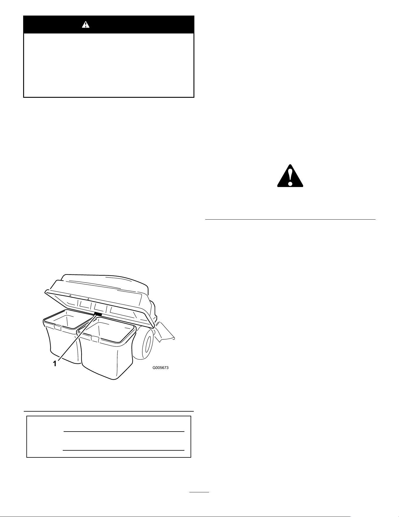
decal136-4164
136-4164
1. W arning—read the Operator ’ s Manual . 4. Cutting/dismemberment hazard, impeller—keep away from
moving parts; keep all guards and covers in place.
2. W arning—hearing protection must be worn.
5. Cutting/dismemberment hazard, impeller—disengage the
PT O, remove the key , and wait for all moving parts to stop.
3. Thrown object hazard—do not operate the blower without the
entire system installed and latched.
6. W arning; loss of traction—do not operate with only
counterbalance weights installed; do not operate with only
E-Z V ac installed; operate only with both E-Z V ac and
counterbalance weights installed.
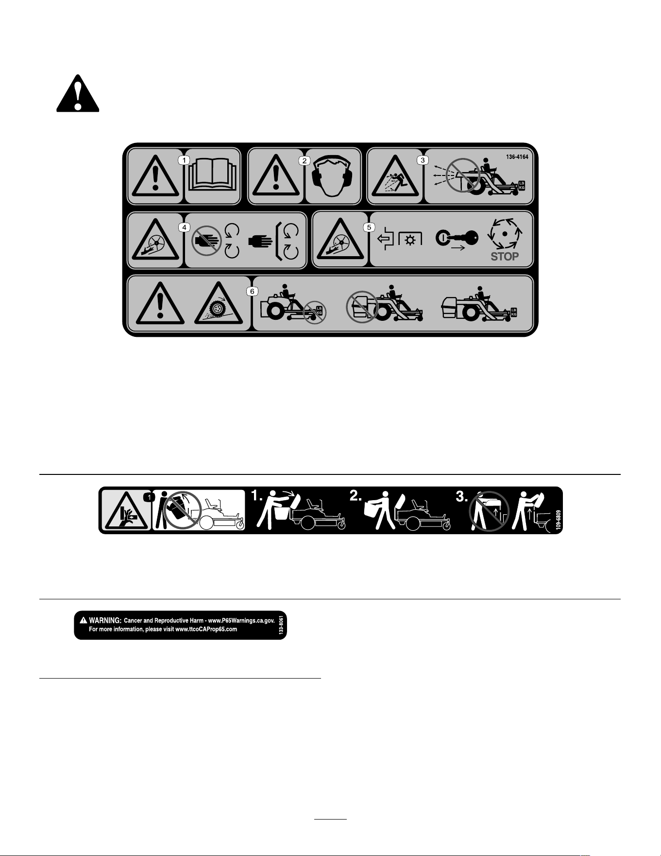
decal109-6809
109-6809
1. Crushing hazard of hand—do not remove the whole bagger from the machine; open the bagger top and then remove the bag(s)
from the bagger . Do not remove the bagger top when it is closed; open the bagger top and then remove it.
decal133-8061
133-8061
5

Setup
Loose Parts
Use the chart below to verify that all parts have been shipped.
Procedure Description
Qty .
Use
1
No parts required
–
Prepare the machine.
W eight tray 1
Left weight-tray mount
1
Right weight-tray mount 1
Suitcase weight—16 kg (35 lb)
1
Retaining rod 1
Bolt (3/8 x 1-1/4 inches)
2
Flange nut (3/8 inch)
4
Carriage bolt (3/8 x 1 inch)
2
2
Self-tapping bolt (5/16 x 3/4 inch)
2
Install the weight.
3
No parts required
–
Remove the grass deector and belt
cover .
Blower support 1
Hex washer-head screw (3/8 x 3/4 inch)
2
Baf e
1
Carriage bolt (5/16 x 3/4 inch)
4
4
Flange nut (5/16 inch)
4
Install the baf e and blower support.
Pulley assembly 1
5
Belt cover 1
Install the pulley assembly and belt
cover .
Stabilizer bracket
1
Carriage bolt (5/16 x 3/4 inch)
2
Locknut (5/16 inch)
4
Self-tapping screw (5/16 x 3/4 inch)
2
Bolt (5/16 x 1 inch)
2
Pivot frame
1
Hairpin cotter 2
Rod 2
6
W asher 2
Install the attachment mount.
Latch rod 1
7
Hairpin cotter 1
Install the latch rod.
Bagger top 1
Bagger screen 1
8
Hairpin cotter 2
Assemble the bagger top.
Bag frame
2
9
Grass bag
2
Assemble the grass bags.
10
Grass bag assembly
2 Install the bagger top.
1 1
Blower assembly 1 Install the blower assembly .
Powered bagger cover 1
12
Blower belt 1
Install the blower belt and powered
bagger cover .
6

Procedure Description
Qty .
Use
Upper tube 1
Screw (1/4 x 3/4 inches)
2
W asher (1/4 inch)
2
Locknut (1/4 inch)
2
13
Lower tube 1
Install the discharge tubes.
Determine the left and right sides of the machine from the normal operating position.
1
Preparing the Machine
No Parts Required
Procedure
Perform the following procedure to prepare the
machine for attaching the blower and nishing kit.
1. Park the machine on a level surface.
2. Disengage the blade-control switch, engage
the parking brake, and move the motion-control
levers outward to the NEUTRAL - LOCK position.
3. Shut of f the engine and remove the key .
4. Ensure that the machine is secure from
movement before you begin to work on it.
5. Repair all bent or damaged areas of machine
deck and replace any missing parts.
6. Clean the machine of any debris on the machine
deck or rear part of the machine to ease
installation.
2
Installing the W eight
Parts needed for this procedure:
1 W eight tray
1
Left weight-tray mount
1 Right weight-tray mount
1
Suitcase weight—16 kg (35 lb)
1 Retaining rod
2
Bolt (3/8 x 1-1/4 inches)
4
Flange nut (3/8 inch)
2
Carriage bolt (3/8 x 1 inch)
2
Self-tapping bolt (5/16 x 3/4 inch)
Procedure
CAUTION
The bagger changes the weight distribution of
the machine. Operating the machine without
the front weights may cause an unstable
condition, which could result in a loss of
control.
Ensure that the front weights are properly
installed before operating the machine with
the bagger attachment.
1. Remove the existing bolt and nut from the left
and right side of the platform where you will
install the weight-tray mounts.
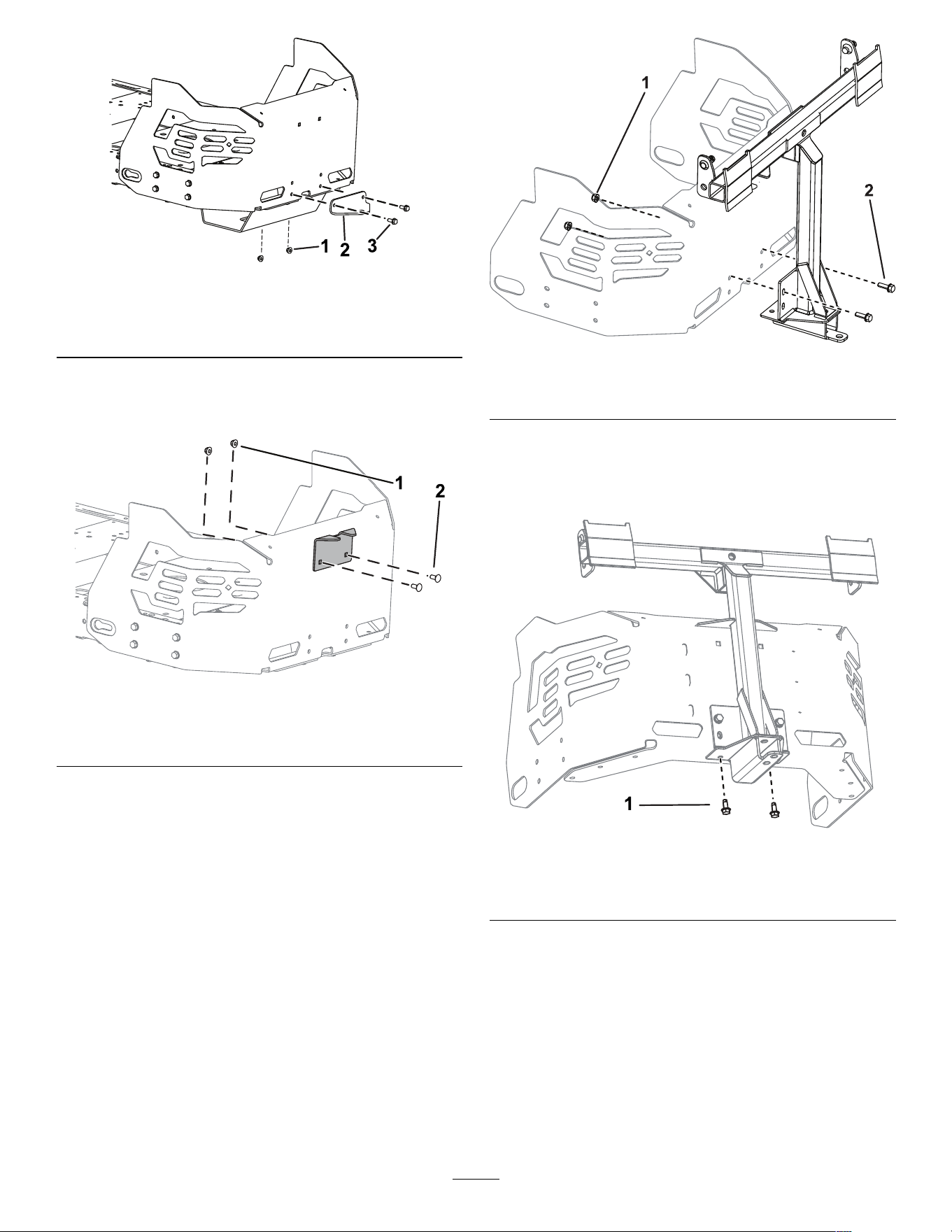
2. Use the 2 self-tapping bolts (5/16 x 3/4 inch), 2
bolts (3/8 x 1-1/4 inches), and ange nuts (3/8
inch) to secure the left and right weight-tray
mounts to the machine ( Figure 3 ).
7
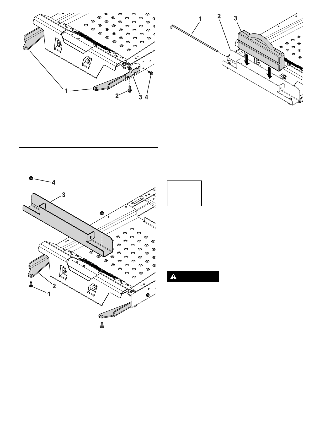
g196533
Figure 3
Cutaway view
1. W eight-tray mounts
3. Flange nut (3/8 inch)
2. Bolt (3/8 x 1-1/4 inches) 4. Self-tapping bolt (5/16 x
3/4 inch)
3. Use the 2 carriage bolts (3/8 x 1 inch) and ange
nuts to secure the weight tray to the mounts
( Figure 4 ).
g196549
Figure 4
1. Carriage bolt (3/8 x 1 inch)
3. W eight tray
2. W eight-tray mount
4. Flange nut (3/8 inch)
4. Insert the suitcase weight into the weight tray
with the groove side facing toward the front of
the machine ( Figure 5 ).
g196560
Figure 5
1. Retaining rod
3. Suitcase weight
2. W eight tray
5. Insert the retaining rod into the tray and rotate it
into the locked position ( Figure 5 ).
Important: Remove the suitcase weight whenever
you remove the bagger attachment.
3
Removing the Grass
Deector and Belt Cover
No Parts Required
Procedure
W ARNING
An uncovered discharge opening could allow
the machine to throw objects toward you or
bystanders and result in serious injury . Also,
contact with the blade could occur .
Never operate the lawn mower unless you
install a mulch plate, discharge deector , or
grass-collection system.
Inspect the grass deector for damage before each
use. Replace any damaged parts before use.
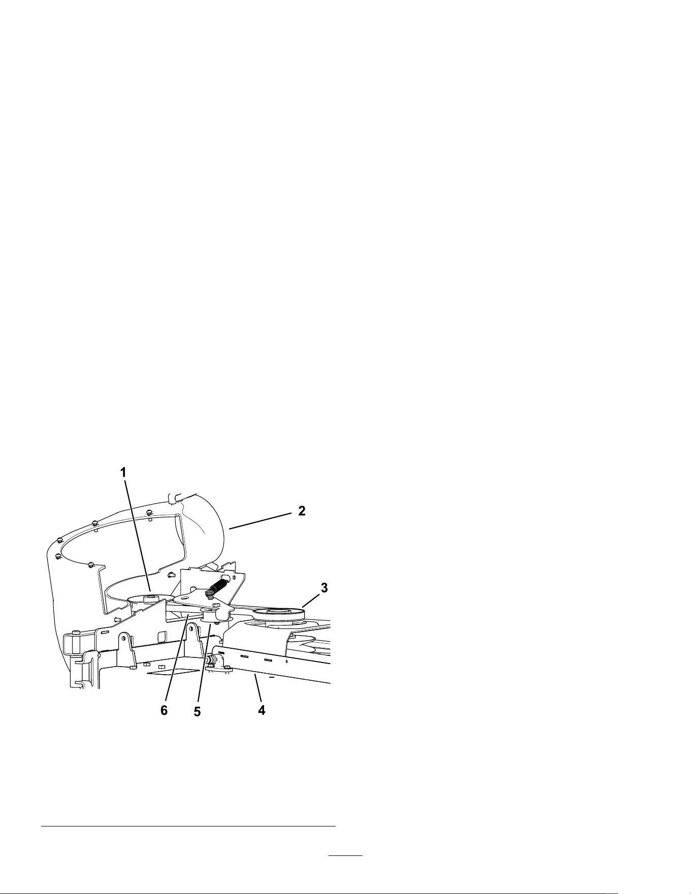
1. Disengage the spring from the notch in the
deector bracket and remove the cotter pin (CE
models only), slide the rod out of the welded
deck brackets, spring, and discharge deector
( Figure 6 ).
8
Note: Y our chute may look dif ferent than the
one pictured.
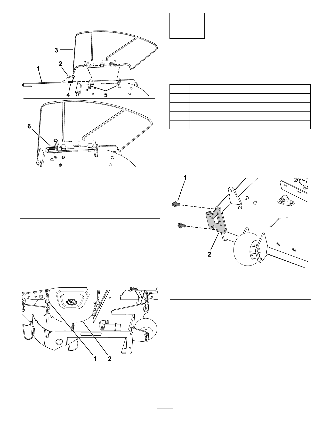
g190642
Figure 6
1. Rod
4. Spring
2. Cotter pin (CE models
only)
5. Deck brackets
3. Deector 6. Spring installed over the
rod
2. Remove the deector ( Figure 6 ).
3. Remove the 4 screws (1/4 x 1/2 inch) securing
the right belt cover , and remove the belt cover
( Figure 7 ).
Note: Retain the 4 screws (1/4 x 1/2 inch) for
installation in Procedure 5 Installing the Pulley
Assembly , Belt Cover , and Shoulder Bolt ( page
1 1 ) .
g200974
Figure 7
1. Screw (1/4 x 1/2 inch)
2. Belt cover
4
Installing the Bafe and
Blower Support
Parts needed for this procedure:
1 Blower support
2
Hex washer-head screw (3/8 x 3/4 inch)
1
Baf e
4
Carriage bolt (5/16 x 3/4 inch)
4
Flange nut (5/16 inch)
Procedure
1. Install the blower support to the mower deck
using 2 hex washer-head screws (3/8 x 3/4 inch)
as shown in Figure 8 .
g201299
Figure 8
1. Hex washer-head screw
(3/8 x 3/4 inch)
2. Blower support
9
2. Remove the existing bolt and nut from the
mower deck ( Figure 9 ).
Important: For 48-inch and 60-inch mower
decks, there is only one bolt and nut that you
can remove.
For 54-inch mower deck, remove the bolt and
nut as shown in Figure 9 .
g206498
Figure 9
1. Existing bolt 2. Existing nut
3. Install the left side of the baf e using a carriage
bolt (5/16 x 3/4 inch) and ange nut (5/16 inch)
as shown in Figure 10 .
4. Loosen the 2 carriage bolts (5/16 x 3/4 inch) in
the baf e slots, and slide the baf e until the hole
aligns with the hole in the mower deck ( Figure
10 ).
5. Install baf e as shown in Figure 10 .
Important: Ensure that you use the correct
hole for the bafe; refer to Figure 10 .
6. T ighten the 2 carriage bolts (5/16 x 3/4 inch) in
the baf e slots ( Figure 10 ).
g206496
Figure 10
54-inch mower deck shown
1. Inner baf e
6. Install this carriage bolt
(5/16 x 3/4 inch) and
ange nut (5/16 inch) after
sliding the baf e.
2. Hole for 48-inch and
60-inch mower deck
installation.
7. Slots in the baf e
3. Hole for 54-inch mower
deck installation.
8. Loosen these 2 carriage
bolts (5/16 x 3/4 inch) and
2 ange nut (5/16 inch).
4. Right blade 9. Install this carriage bolt
(5/16 x 3/4 inch) and
ange nut (5/16 inch) rst.
5. Outer baf e
10
5
Installing the Pulley
Assembly , Belt Cover ,
and Shoulder Bolt
Parts needed for this procedure:
1 Pulley assembly
1 Belt cover
Procedure
1. Remove the nut and washer from the right
mower deck pulley .
2. Install the pulley assembly to the right mower
deck pulley with the previously removed nut and
washer ( Figure 1 1 ).
Important: For 48-inch mower decks, use
the small blower pulley .
For 54-inch and 60-inch mower decks, use
the large blower pulley .
3. T orque the nut to 136 to 149 N∙m (100 to 1 10
ft-lb).
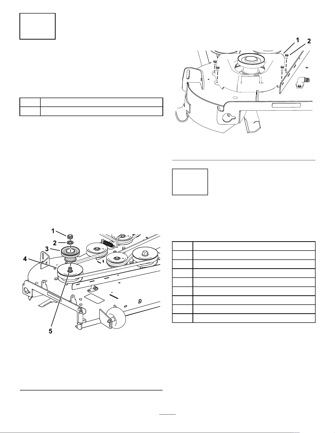
g201880
Figure 1 1
54-inch mower deck shown
1. Existing pulley nut
4. Existing deck (spindle)
pulley
2. Existing washer
5. Spindle
3. Blower pulley
4. Install the new belt cover over the pulley
assembly using the 4 previously removed
screws (1/4 x 1/2 inch) as shown in Figure 12 .
g201435
Figure 12
1. Belt cover
2. Screw (1/4 x 1/2 inch)
6
Installing the Attachment
Mount
Parts needed for this procedure:
1
Stabilizer bracket
2
Carriage bolt (5/16 x 3/4 inch)
4
Locknut (5/16 inch)
2
Self-tapping screw (5/16 x 3/4 inch)
2
Bolt (5/16 x 1 inch)
1
Pivot frame
2 Hairpin cotter
2 Rod
2 W asher
Procedure
1. Remove the existing 2 bolts, 2 nuts, and hitch
bracket from the bottom of the engine guard
( Figure 13 ).
1 1
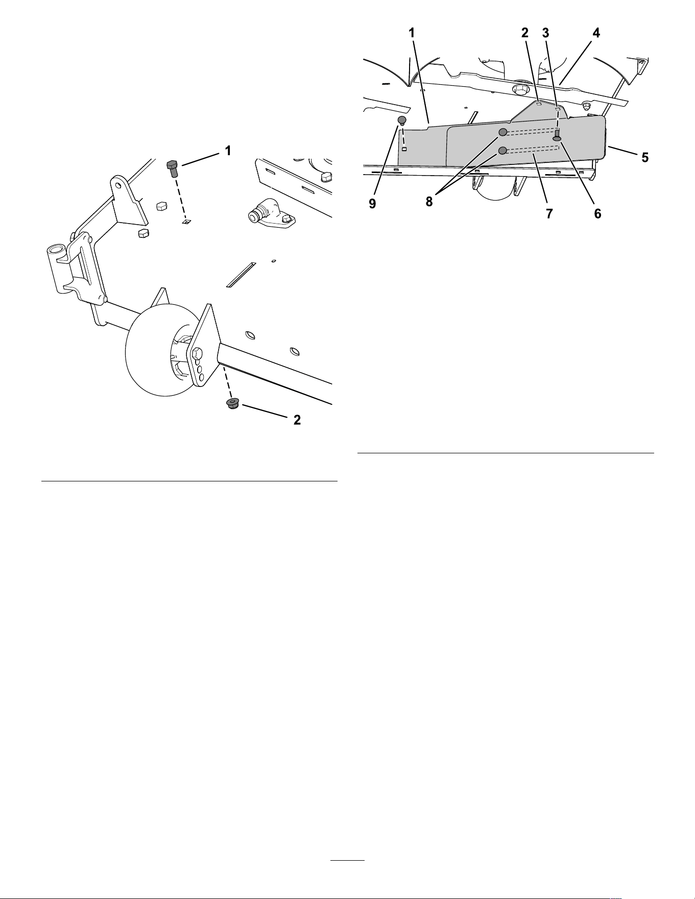
g308798
Figure 13
1. Nut 3. Bolt
2. Existing hitch bracket
2. Install the stabilizer bracket to the engine guard
using 2 carriage bolts (5/16 x 3/4 inch) and 2
locknuts (5/16 inch) as shown in Figure 14 .
g308799
Figure 14
1. Locknut (5/16 inch) 2. Carriage bolt (5/16 x 3/4
inch)
3. Remove the existing 2 self-tapping screws from
the bottom of the machine frame ( Figure 16 ).
4. Loosely install the pivot frame to the machine
frame using 2 bolts (5/16 x 1 inch) and 2 locknuts
(5/16 inch) as shown in Figure 15 .
g302477
Figure 15
1. Locknut (5/16 inch) 2. Bolt (5/16 x 1 inch)
5. Position the pivot frame upward, and secure the
pivot frame to the bottom of the machine frame
using 2 self-tapping screws (5/16 x 3/4 inch) as
shown in Figure 16 .
g308797
Figure 16
1. Self-tapping screw (5/16 x
3/4 inch)
2. Pivot frame
6. T ighten the 2 bolts (5/16 x 1 inch) and 2 locknuts
(5/16 inch) as shown in Figure 15 .
7. Install the bent, ared end of a rod into the keyed
slot in the left side of the machine frame, and
move the rod rearward to seat it in the frame
( Figure 17 ).
Note: Repeat this step for the right side of the
machine.
12
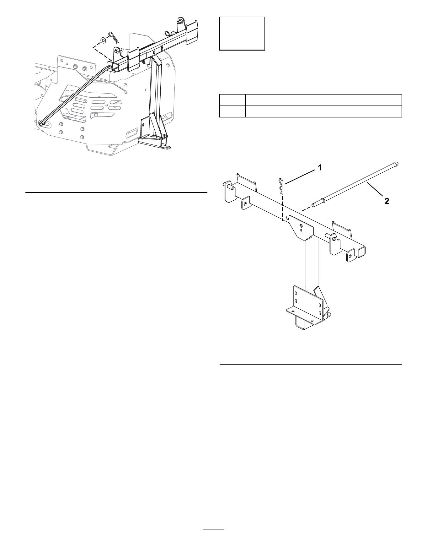
g308335
Figure 17
Left side shown
8. Insert the bent ends of the rods into the
attachment mount as shown in Figure 17 and
secure the end of each rod with a washer and
hairpin cotter .
7
Installing the Latch Rod
Parts needed for this procedure:
1 Latch rod
1 Hairpin cotter
Procedure
Install the latch rod with a hairpin cotter ( Figure 18 ).
g201213
Figure 18
1. Hairpin cotter 2. Latch rod
13
8
Assembling the Bagger T op
Parts needed for this procedure:
1 Bagger top
1 Bagger screen
2 Hairpin cotter
Procedure
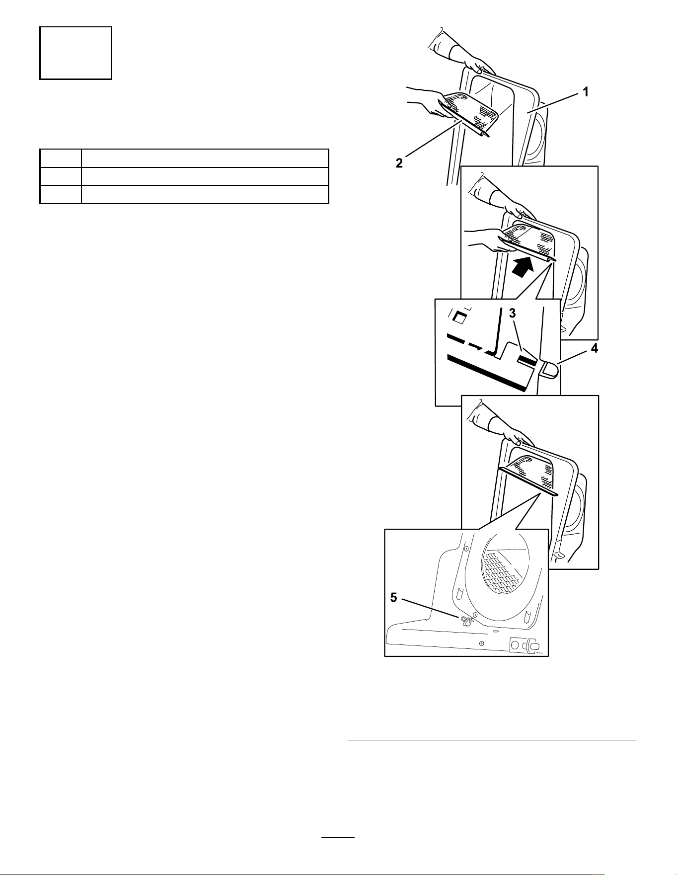
1. T urn the bagger top over .
2. Install the screen as shown in Figure 19 and
ensure that it slopes down toward the collection
bags.
Note: Make sure that the screens snap into
place and the tabs engage the bagger top.
g201881
Figure 19
1. Bagger top
4. Slot in bagger top
2. Screen
5. Hairpin cotter
3. Screen tab
14
9
Assembling the Grass Bags
Parts needed for this procedure:
2
Bag frame
2
Grass bag
Procedure
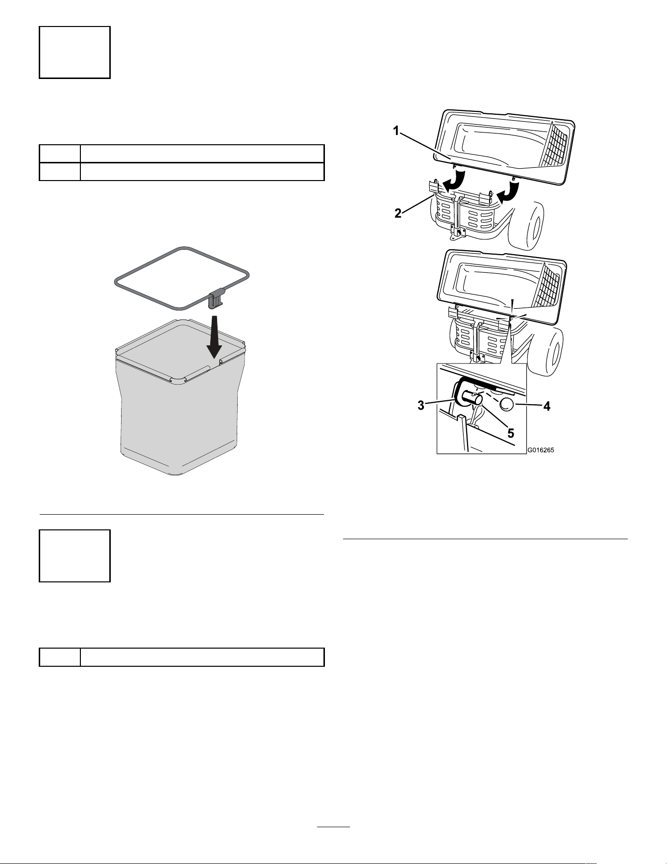
Snap the 2 bag frames to the 2 grass bags.
g453040
Figure 20
10
Installing the Bagger T op
Parts needed for this procedure:
2
Grass bag assembly
Procedure
1. Install the bagger top to the bagger frame.
Note: Y our bagger may look dif ferent than the
one shown.
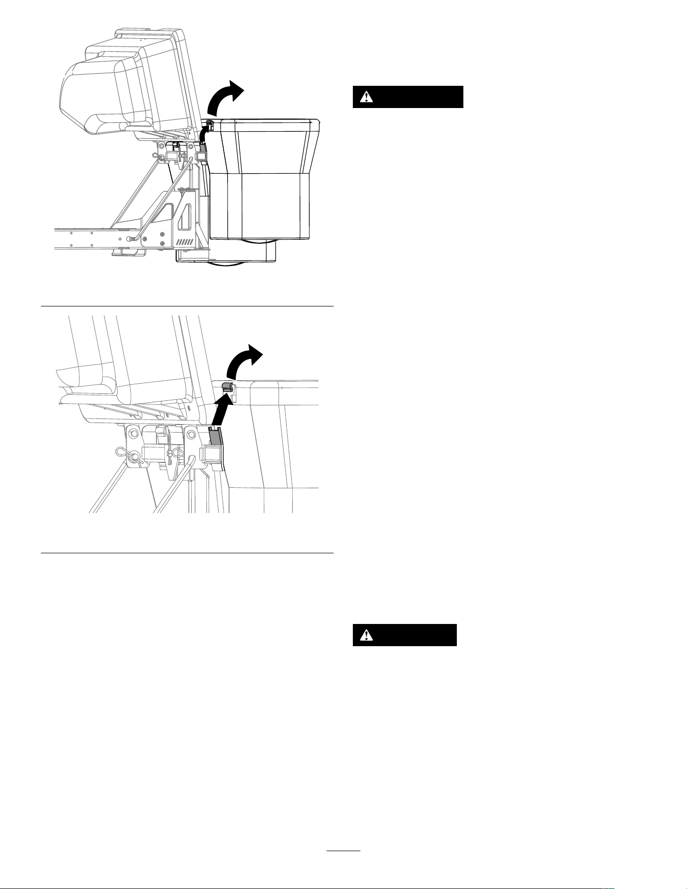
2. Slide the brackets over the posts in the bagger
frame and install the circular cotter pin into the
hole in the right hand post ( Figure 21 ).
3. Rotate the bagger hood down to the operating
position.
Note: T o remove the circular cotter pin,
continue to rotate it in the same direction as
installed.
g016265
Figure 21
1. Bagger hood
4. Circular cotter pin
2. Bagger frame
5. Post
3. Bracket, bagger hood
15
4. Lift the bagger top and install the bags
assembled in 9 Assembling the Grass Bags
( page 15 ) by sliding the bag frame hooks onto
the retaining brackets ( Figure 22 ).
g300378
Figure 22
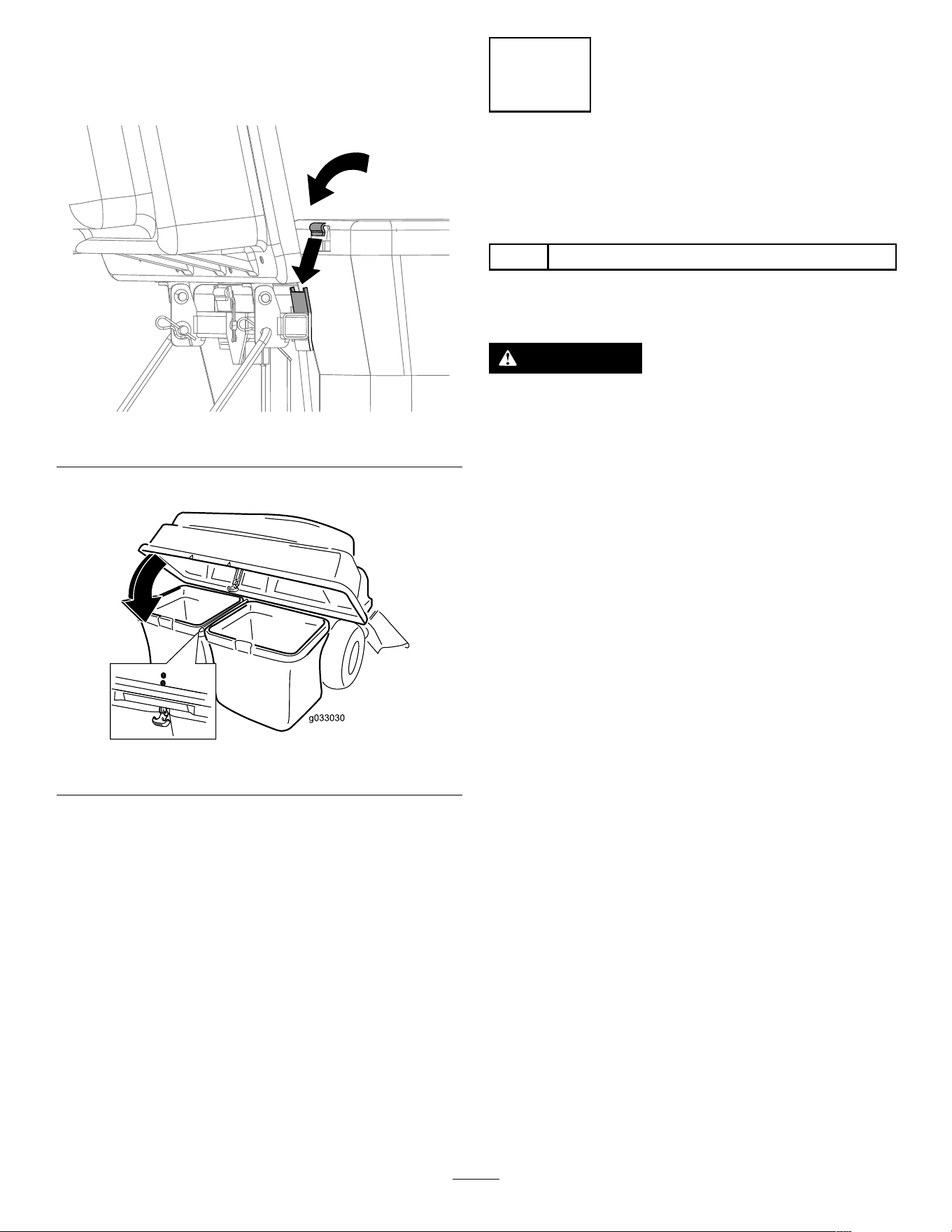
5. Lower the bagger top onto the bags ( Figure 23 ).
g033030
Figure 23
6. Secure the hood with the latch ( Figure 23 ).
1 1
Installing the Blower
Assembly
Parts needed for this procedure:
1 Blower assembly
Procedure
W ARNING
An uncovered discharge opening allows the
lawn mower to throw objects toward you or
bystanders, resulting in serious injury . Also,
contact with the blade could occur .
• Never operate the lawn mower without a
cover plate, a mulch plate, or a grass chute
and catcher .
• Make sure that the grass deector is
installed when you remove the grass chute
and catcher .
Important: Install the side-discharge chute when
you remove the bagger and blower .
Important: Save all the hardware and the
side-discharge chute.
1. If necessary , install the belt onto the blower
pulley ( Figure 26 ).
2. Insert the blower pivot pin into the blower
support and rotate the blower assembly inward
toward the machine ( Figure 24 ).
Note: The blower assembly should
automatically latch as shown in Figure 25 .
16
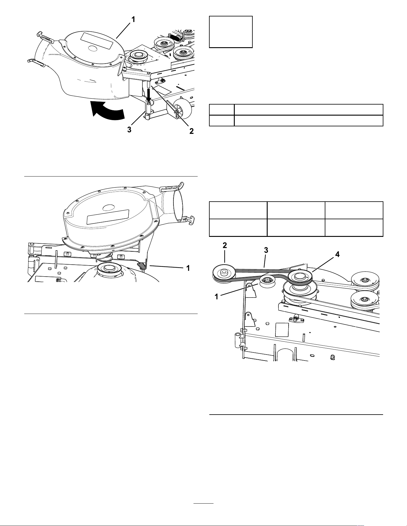
g201514
Figure 24
1. Blower assembly 3. Blower support
2. Blower pivot pin
g201893
Figure 25
1. Blower latch
12
Installing the Blower Belt
and Powered Bagger Cover
Parts needed for this procedure:
1 Powered bagger cover
1 Blower belt
Procedure
1. Install the belt around the blower pulley ( Figure
26 and Figure 27 ); refer to 1 1 Installing the
Blower Assembly ( page 16 ) .
Use the following belt based on the mower
deck size:
48-inch Mower
Deck
54-inch Mower
Deck
60-inch Mower
Deck
T oro Part No.
127-0074
T oro Part No.
127-0075
T oro Part No.
127-0076
g201516
Figure 26
Blower Belt Routing
1. Idler/tension pulley
3. Blower belt
2. Blower pulley 4. Drive pulley
17
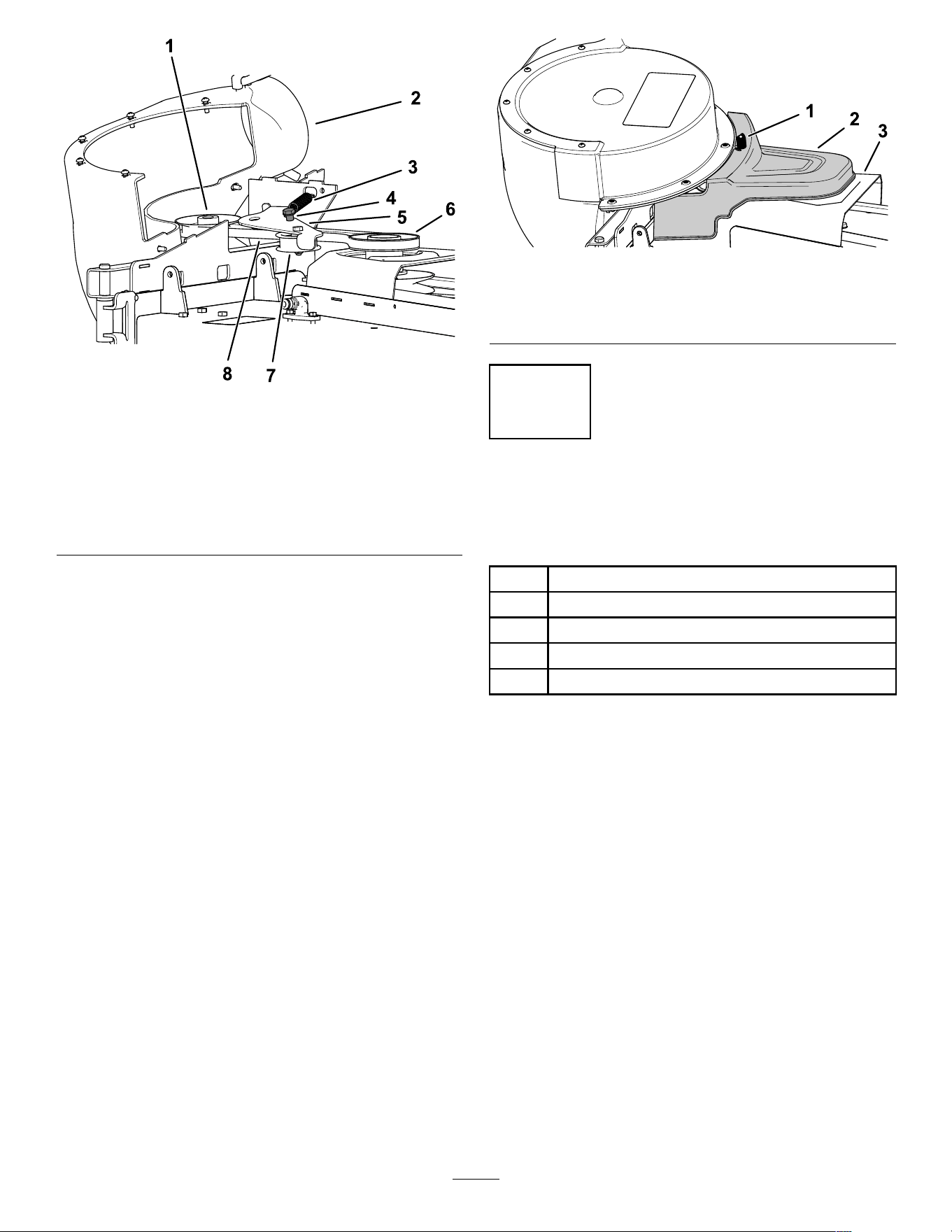
g201513
Figure 27
1. Blower pulley 5. Idler arm
2. Blower in position (housing
portion removed for
illustrative purposes)
6. Drive pulley
3. Spring 7. Idler/tension pulley
4. Idler-pulley post 8. Blower belt
2. Ensure that the belt remains aligned to the
blower pulley while you are installing the blower
assembly .
3. Pull the spring loaded idler pulley away from the
xed spring post, and route the belt around the
mower deck pulley ( Figure 27 ).
Note: Ensure that the belt is routed around the
blower pulley correctly .
4. Route the belt around the drive pulley as
illustrated in Figure 26 and Figure 27 .
5. Install the powered bagger cover over the belt
cover , and secure it by tightening the knob
( Figure 28 ).
g201515
Figure 28
1. Knob 3. Belt cover
2. Powered bagger cover
13
Installing the Discharge
T ubes
Parts needed for this procedure:
1 Upper tube
2
Screw (1/4 x 3/4 inches)
2
W asher (1/4 inch)
2
Locknut (1/4 inch)
1 Lower tube
Procedure
Important: Make sure that the mower deck is in
the lowest height-of-cut position before installing
the discharge tubes.
Note: Remember to install the grass deector when
you remove the bagger from the mower .
1. Disengage the PT O and engage the parking
brake.
2. Shut of f the engine and remove the key .
3. Lower the mower deck to the lowest height-of-cut
position.
4. Remove the bags for viewing the tube under
the hood.
5. Lower and latch the hood.
6. Use both latches to attach the lower tube to the
blower assembly ( Figure 29 ).
Note: Ensure that the notch in the lower tube is
at the bottom when installed ( Figure 31 ).
18
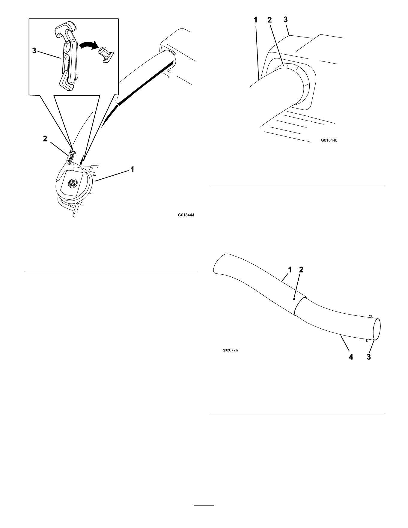
g018444
Figure 29
Lower Discharge T ube Latch
1. Blower assembly 3. Latch
2. Upper latch
7. Make note of where the 2 bolts in the upper tube
are installed.
Note: The hole near the molded arrowheads
will not be used.
8. Remove the 2 bolts in the lower end of the upper
tube.
9. Use the 2 holes as a template for the lower tube.
Note: Retain the hardware.
10. Insert the upper end (no holes) of the upper tube
through the tube seal in the hood by pushing
the tube in until the tube contacts the inside of
the hood.
1 1. Pull the upper tube out slightly so that the seal
extends outward and over the lower tube ( Figure
30 ).
g018440
Figure 30
1. Upper tube 3. Bagger hood
2. Rubber seal protruding out
12. Align the upper tube holes to match the dimples
on the surface of the lower tube.
Note: Ensure that the side prole appears as
shown in Figure 31 .
Note: Do not use the open hole near the
molded arrowheads.
g020776
Figure 31
1. Upper tube
3. Notch at the bottom of the
tube when installed
2. Existing hole (bolt
removed)
4. Lower tube
13. Using the existing holes in the upper tube as
a template, drill 2 holes, 6.5 mm (1/4 inch)
diameter , through the dimples on the lower tube
( Figure 32 ).
19
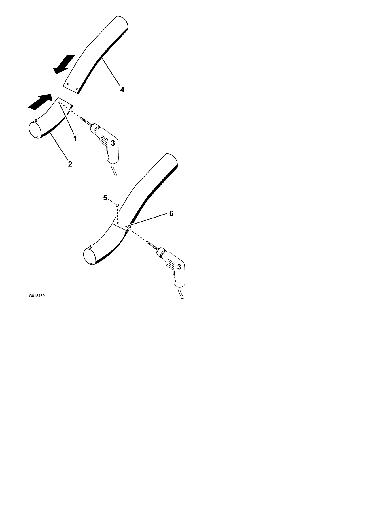
g018439
Figure 32
Drilling Lower Discharge T ube
1. Dimples 4. Upper tube
2. Lower tube
5. Install screw (1/4 x 3/4
inch), washer (1/4 inch),
and locknut (1/4 inch)
here.
3. Drill 6.5 mm (1/4 inch)
diameter hole
6. Upper tube—existing
holes
14. Remove the upper and lower tubes from the
machine.
15. Slide the tubes together and align the holes.
16. Install the washers (1/4 inch) onto the bolts
( Figure 32 ).
17. Using a hex key tool, install the screws (1/4 x
3/4 inch) and washers (1/4 inch) from the inside
of the lower tube and through the existing holes
in the upper tube ( Figure 32 ).
18. Secure the tubes together with the nuts (1/4
inch) as shown in Figure 32 .
19. Insert the upper discharge tube through the tube
seal in the hood.
20. Pull the upper tube out slightly so that the seal
extends outward and over the blower assembly
( Figure 30 ).
21. Use both latches to attach the lower tube to the
blower assembly ( Figure 29 ).
20
Operation
W ARNING
T o avoid personal injury , follow these
procedures:
• Become familiar with all operating and
safety instructions in the Operator's
Manual for the mower before using this
attachment.
• Never remove the discharge tube, bags,
bagger top, or the chute while the engine
is running.
• Always shut the engine off and wait for all
moving parts to stop before clearing an
obstruction from the bagging system.
• Never perform maintenance or make
repairs while the engine is running.
W ARNING
W ithout the grass deector , bagger tubes or
complete bagger assembly mounted in place,
you and others are exposed to blade contact
and thrown debris. Contact with the rotating
mower blade(s) and thrown debris will cause
injury or death.
• Always install the grass deector when
removing the bagger and changing to side
discharge mode.
• If the grass deector is ever damaged,
replace it immediately . The grass deector
routes material down toward the turf.
• Never put your hands or feet under the
mower .
• Never try to clear the discharge area or
mower blades unless you move the power
take off (PT O) to off and rotate the ignition
key to off. Also remove the key and pull
the wire off of the spark plug(s).
• T urn off the engine before unclogging the
discharge chute.
Emptying the Grass Bags
DANGER
Debris, such as leaves, grass, or brush can
catch re. A re in the engine area can cause
personal injury and property damage.
• Keep the engine and mufer area free of
debris accumulation.
• T ake care when opening the bagger cover
to keep debris from falling onto the engine
and mufer area.
• Allow the machine to cool before storing it.
Be careful when lifting or handling a grass bag that is
full. T o empty the grass bags:
1. Park the machine on a level surface and
disengage the blade control switch.
2. Move the motion control levers outward to
the neutral lock position, shut of f the engine,
remove the key , set the parking brake and wait
for all moving parts to stop before leaving the
operating position.
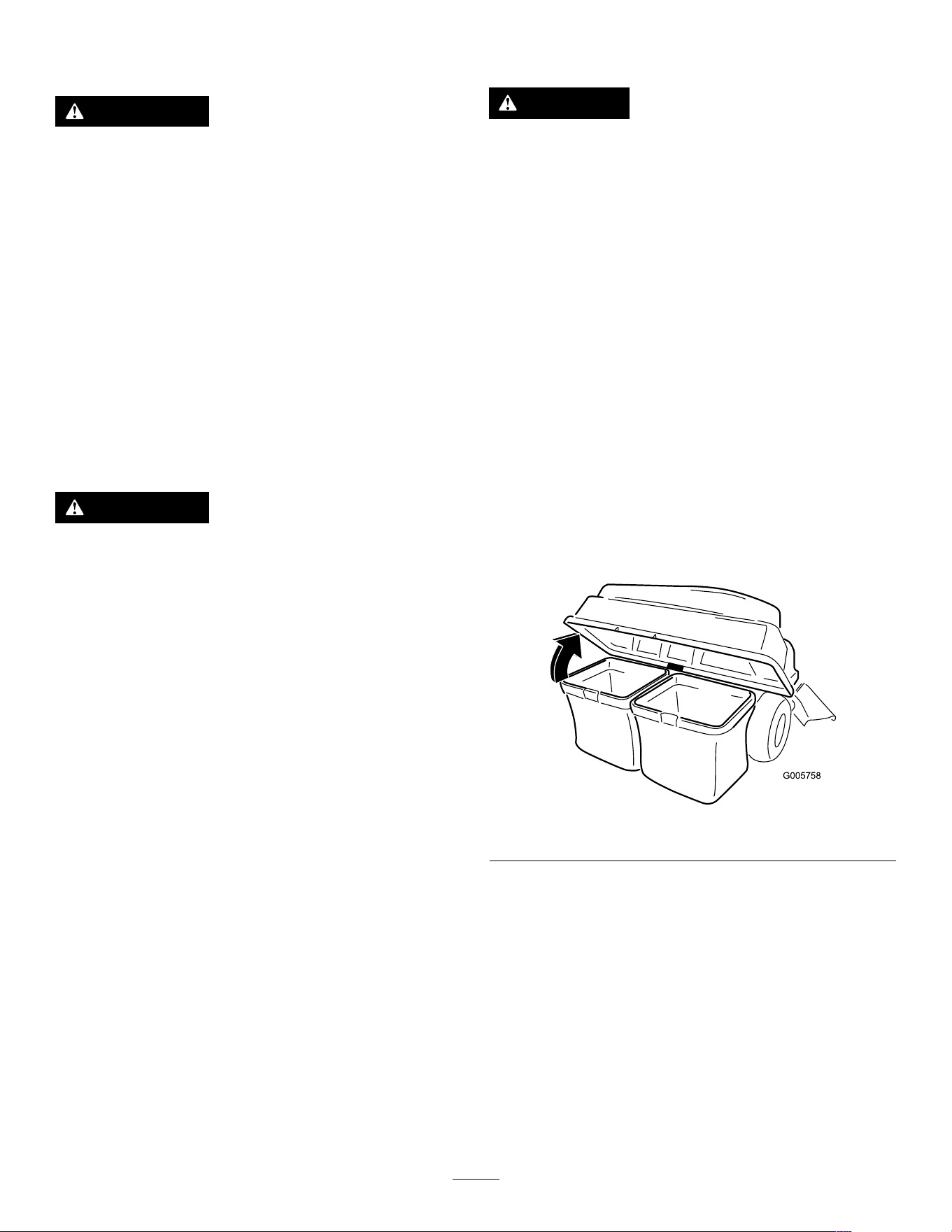
3. Open (raise) the bagger top ( Figure 33 ).
g005758
Figure 33
4. Compress debris into the bags. With both
hands, lift up on the bag and unhook it from the
retaining bracket. Empty the bag. Repeat the
procedure for the other bag.
21
g300218
Figure 34
g300217
Figure 35
5. Install the bags by sliding the bag frame hooks
onto the retaining brackets.
6. Lower the bagger top onto the bags.
Clearing Obstructions from
the Bagger
W ARNING
When the bagger is in operation, the blower
is rotating and can cut off or injure hands and
ngers.
• Before adjusting, cleaning, repairing
and inspecting the blower , and before
unclogging the chute, shut off the engine
and wait for all moving parts to stop.
Remove the key .
• Use a stick or similar object, not your
hands, to remove an obstruction from the
blower and tube.
• Keep your face, hands, feet, and any other
part of your body or clothing away from
concealed, moving, or rotating parts.
1. Park the machine on a level surface and
disengage the blade control switch.
2. Move the motion control levers outward to the
neutral lock position, stop the engine, remove
the key , set the parking brake and wait for
all moving parts to stop before leaving the
operating position.
3. Check the grass bags and empty them if they
are full.
4. Remove and separate the discharge tube and
chute from the bagger top and mower . Using
a stick or similar object, carefully remove and
clear the obstruction from the mower , discharge
tube, chute, and the bagger top.
5. After you remove the obstruction, install the
complete bagger system and resume operation.
Removing the Bagger
CAUTION
Failing to remove the front bagger weights
and operating the machine without the bagger
attachment may cause an unstable condition,
which could result in a loss of control.
• Always remove the front weights when
removing the bagger attachment.
• Never operate the machine without the
bagger attachment and the front weights
installed.
Y ou can remove the bagger by repeating the Setup
sections from all installed bagger related kits in
22

reverse order . If weights are installed, always remove
the front bagger weights when removing the bagger
attachments.
Note: It is necessary only to remove the cutof f baf e
when installing a mulching kit.
Operating T ips
T ips for Bagging
Remembering the Size of the
Machine with the Attachment
Remember that the machine is longer and wider with
this attachment installed. By turning too sharply in
conned places, you may damage the attachment.
T rimming
Always trim with the left side of the mower . Do not trim
with the right side of the mower because you could
damage the bagger chute and discharge tube.
Cutting Height
Do not set the mower cutting height too low because
long grass surrounding the mower can prevent air
from getting under the mower and entering the
bagging system. If enough air does not get under the
mower , the bagging system will plug.
Cutting Frequency
Cut the grass often, especially when it grows rapidly .
Y ou will have to cut your grass twice if it gets
excessively long.
Cutting T echnique
For best lawn appearance, be sure to slightly overlap
the mower into the previously cut area. This helps
reduce the load on the engine and reduces the chance
of plugging the chute and discharge tube.
Bagging Speed
Most often you will bag with the mower throttle in the
F AST position and drive at a normal ground speed.
However , in extremely dry and dusty grass, you may
want to slightly reduce the throttle speed and increase
the ground speed of the mower . The bagging system
may plug if you drive too fast and the engine speed
gets too slow . On hills, it may be necessary to slow
the mower ground speed. This helps maintain the
engine speed and bagging ef ciency . Mow downhill
whenever possible.
CAUTION
As the bagger lls, extra weight is added to
the back of the machine. If you stop and
start suddenly on hills, you may lose steering
control or the machine may tip.
• Do not start or stop suddenly when going
uphill or downhill. A void uphill starts.
• If you do stop the machine when going
uphill, disengage the blade control. Then
back down the hill using a slow speed.
• A void sudden turns or rapid speed
changes on slopes.
• Never operate the machine without the
bagger attachment and the front weights
installed.
Bagging Long Grass
Excessively long grass is heavy and may not be
propelled completely into the grass bags. If this
happens, the discharge tube and chute may plug. T o
avoid plugging the bagging system, mow the grass
at a high height of cut, then lower the mower to your
normal cutting height and repeat the bagging process.
Bagging W et Grass
Always try to cut grass when it is dry because your
lawn will have a neat appearance. If you must cut wet
grass, use the conventional side-discharge feature of
the mower . Several hours later , when the clippings
are dry , install the complete bagger attachment and
vacuum up the grass clippings.
Signs of Plugging
As you are bagging, a small amount of grass clippings
normally blow out the front of the mower . An excessive
amount of clippings blowing out indicates that the
bags are full or the system is plugged.
23

Maintenance
Note: Determine the left and right sides of the machine from the normal operating position.
Recommended Maintenance Schedule(s)
Maintenance Service
Interval
Maintenance Procedure
After the rst 8 hours
• Inspect the blower belt.
• Inspect the bagger .
After each use
• Clean the hood screen.
• Clean the bagger .
Every 25 hours
• Inspect the blower belt.
Every 100 hours
• Inspect the bagger .
W ARNING
If you leave the key in the key switch, someone could accidently start the engine and seriously
injure you or other bystanders.
Remove the key and disconnect the wire from the spark plug before you do any maintenance.
Set the wire aside so that it does not accidentally contact the spark plug.
W ARNING
Engines can become hot when they are operating. Severe burns can occur from contacting hot
surfaces.
Allow engines, especially the mufer , to cool before touching.
W ARNING
Debris, such as leaves, grass, or brush can catch re. A re in the engine area can cause
personal injury and property damage.
• Keep the engine and mufer area free of debris accumulation.
• T ake care when opening the bagger cover to keep debris from falling onto the engine and
mufer area.
• Allow the machine to cool before storing it.
Preparing for Maintenance
Do the following steps before preforming maintenance
on the machine:
1. Park the machine on a level surface.
2. Disengage the PT O, move the motion control
levers to the NEUTRAL - LOCK position, and engage
the parking brake.
3. Shut of f the engine and remove the key .
4. Clean the mower of any debris on the deck or
rear part of the mower to ease maintenance.
Cleaning the Hood Screen
Service Interval : After each use
1. Open the bagger hood.
2. Clean the debris from the screen.
3. Close the bagger hood.
24
Cleaning the Bagger and
Bags
Service Interval : After each use
1. W ash the inside and outside of the bagger hood,
bags, tube, and the underside of the mower .
Note: Use a mild automotive detergent to
remove dirt.
2. Make sure that you remove matted grass from
all parts.
3. After washing all parts, let them dry thoroughly .
Note: With all parts installed, start and run the
machine for a minute to assist in drying.
Inspecting the Blower Belt
Service Interval : After the rst 8 hours
Every 25 hours
Check belts for cracks, frayed edges, burn marks or
any other damage. Replace damaged belts.
Replacing the Blower Belt
1. Remove the plastic belt cover .
2. Pull back on the spring-loaded idler pulley to
relieve the belt tension ( Figure 36 ).
g202246
Figure 36
1. Blower pulley 4. Mower deck
2. Blower in position (housing
portion removed for
illustrative purposes)
5. Idler/tension pulley
3. Drive pulley 6. Blower belt
3. Remove the existing bagger belt from the
mower-deck pulley .
4. Remove the blower from the mower deck.
5. Remove the existing bagger belt from the blower
pulleys.
6. Install the new belt around the blower pulleys
( Figure 36 ).
7. Install the blower onto the blower support.
8. Install the new belt around the mower-deck
pulley ( Figure 36 ).
9. Pull back on the spring loaded idler pulley and
install the belt onto the spring-loaded idler pulley
( Figure 36 ).
Inspecting the Bagger
Service Interval : Every 100 hours
After the rst 8 hours
1. Check the upper tube, lower tube, bagger hood,
and the blower assembly .
Note: Replace these parts if they are cracked
or broken.
2. Check the bags, bagger frame, and screen.
Note: Replace any parts that are cracked or
broken.
3. T ighten all nuts bolts and screws.
Inspecting the Mower
Blades
1. Inspect the mower blades regularly and
whenever a blade strikes a foreign object.
2. If blades are badly worn or damaged, install new
blades; refer to your machine Operator's Manual
for complete blade maintenance.
25

Storage
Storing the Bagger
Attachment
1. Clean the bagger attachment; refer to Cleaning
the Bagger Attachment.
2. Inspect the bagger attachment for damage; refer
to Inspecting the Bagger Attachment.
3. Ensure that the grass bags are empty and
thoroughly dry .
4. Store the bagger in a clean, dry place, out
of direct sunlight. This protects the plastic
parts and extends the life of the bagger . If you
must store the bagger outside, cover it with a
weatherproof cover .
26

T roubleshooting
Problem
Possible Cause Corrective Action
1. The cutting blade(s) are bent or
unbalanced.
1. Install new cutting blade(s).
2. The blade-mounting bolt is loose. 2. T ighten the blade-mounting bolt.
3. There is a loose blower pulley or pulley
assembly .
3. T ighten the appropriate pulley .
4. The bagger belt is worn. 4. Replace the belt.
There is abnormal vibration.
5. The blower fan blade(s) are bent or
unbalanced.
5. Contact an Authorized Service Dealer .
1. The engine speed is too low .
1. Always operate the engine at full
throttle.
2. The screen in the bagger hood is
plugged.
2. Remove debris, leaves, or grass
clippings from the screen.
3. The bagger belt is loose. 3. Replace the bagger belt.
4. There is a plugged tube or blower . 4. Locate and remove the plugged debris.
Reduced bagging performance
5. The bags are full.
5. Empty the hopper .
1. The bags are too full. 1. Dump more frequently .
2. The engine speed is too low .
2. Always operate the engine at full
throttle.
3. The grass is too wet.
3. Cut grass when it is dry .
4. The grass is too long.
4. Cut no more than 51 to 76 mm (2 to
3 inches) or 1/3 of the grass height,
whichever is less.
5. The screen in the bagger hood is
plugged.
5. Remove debris, leaves, or grass
clippings from the screen.
6. The ground speed is too fast. 6. Drive slower at full throttle.
The blower and tubes plug too frequently .
7. The bagger belt is worn. 7. Replace the belt.
1. The bags are too full. 1. Dump more frequently .
2. The ground speed is too fast.
2. Drive the machine at slow ground
speed while operating the engine at
full throttle.
Debris blowout
3. The mower deck is not leveled.
3. See the machine Operator's Manual
for leveling the mower deck.
1. The blower is plugged. 1. Remove debris, leaves, or grass
clippings from the blower impeller .
The blower impeller does not spin freely .
2. The impeller is not aligned.
2. Contact an Authorized Service Dealer .
27

California Proposition 65 W arning Information
What is this warning?
Y ou may see a product for sale that has a warning label like the following:
W ARNING: Cancer and Reproductive Harm—www .p65W arnings.ca.gov .
What is Prop 65?
Prop 65 applies to any company operating in California, selling products in California, or manufacturing products that may be sold in or brought into
California. It mandates that the Governor of California maintain and publish a list of chemicals known to cause cancer , birth defects, and/or other
reproductive harm. The list, which is updated annually , includes hundreds of chemicals found in many everyday items. The purpose of Prop 65 is to
inform the public about exposure to these chemicals.
Prop 65 does not ban the sale of products containing these chemicals but instead requires warnings on any product, product packaging, or literature with
the product. Moreover , a Prop 65 warning does not mean that a product is in violation of any product safety standards or requirements. In fact, the
California government has claried that a Prop 65 warning “is not the same as a regulatory decision that a product is ‘safe’ or ‘unsafe.’” Many of these
chemicals have been used in everyday products for years without documented harm. For more information, go to https://oag.ca.gov/prop65/faqs-view-all .
A Prop 65 warning means that a company has either (1) evaluated the exposure and has concluded that it exceeds the “no signicant risk level”; or (2)
has chosen to provide a warning based on its understanding about the presence of a listed chemical without attempting to evaluate the exposure.
Does this law apply everywhere?
Prop 65 warnings are required under California law only . These warnings are seen throughout California in a wide range of settings, including but not
limited to restaurants, grocery stores, hotels, schools, and hospitals, and on a wide variety of products. Additionally , some online and mail order
retailers provide Prop 65 warnings on their websites or in catalogs.
How do the California warnings compare to federal limits?
Prop 65 standards are often more stringent than federal and international standards. There are various substances that require a Prop 65 warning
at levels that are far lower than federal action limits. For example, the Prop 65 standard for warnings for lead is 0.5 μg/day , which is well below
the federal and international standards.
Why don’t all similar products carry the warning?
• Products sold in California require Prop 65 labelling while similar products sold elsewhere do not.
• A company involved in a Prop 65 lawsuit reaching a settlement may be required to use Prop 65 warnings for its products, but other companies
making similar products may have no such requirement.
• The enforcement of Prop 65 is inconsistent.
• Companies may elect not to provide warnings because they conclude that they are not required to do so under Prop 65; a lack of warnings for a
product does not mean that the product is free of listed chemicals at similar levels.
Why does T oro include this warning?
T oro has chosen to provide consumers with as much information as possible so that they can make informed decisions about the products they buy and
use. T oro provides warnings in certain cases based on its knowledge of the presence of one or more listed chemicals without evaluating the level of
exposure, as not all the listed chemicals provide exposure limit requirements. While the exposure from T oro products may be negligible or well within the
“no signicant risk” range, out of an abundance of caution, T oro has elected to provide the Prop 65 warnings. Moreover , if T oro does not provide these
warnings, it could be sued by the State of California or by private parties seeking to enforce Prop 65 and subject to substantial penalties.
Rev A