
54-40-0642
58-01-1373
A20D
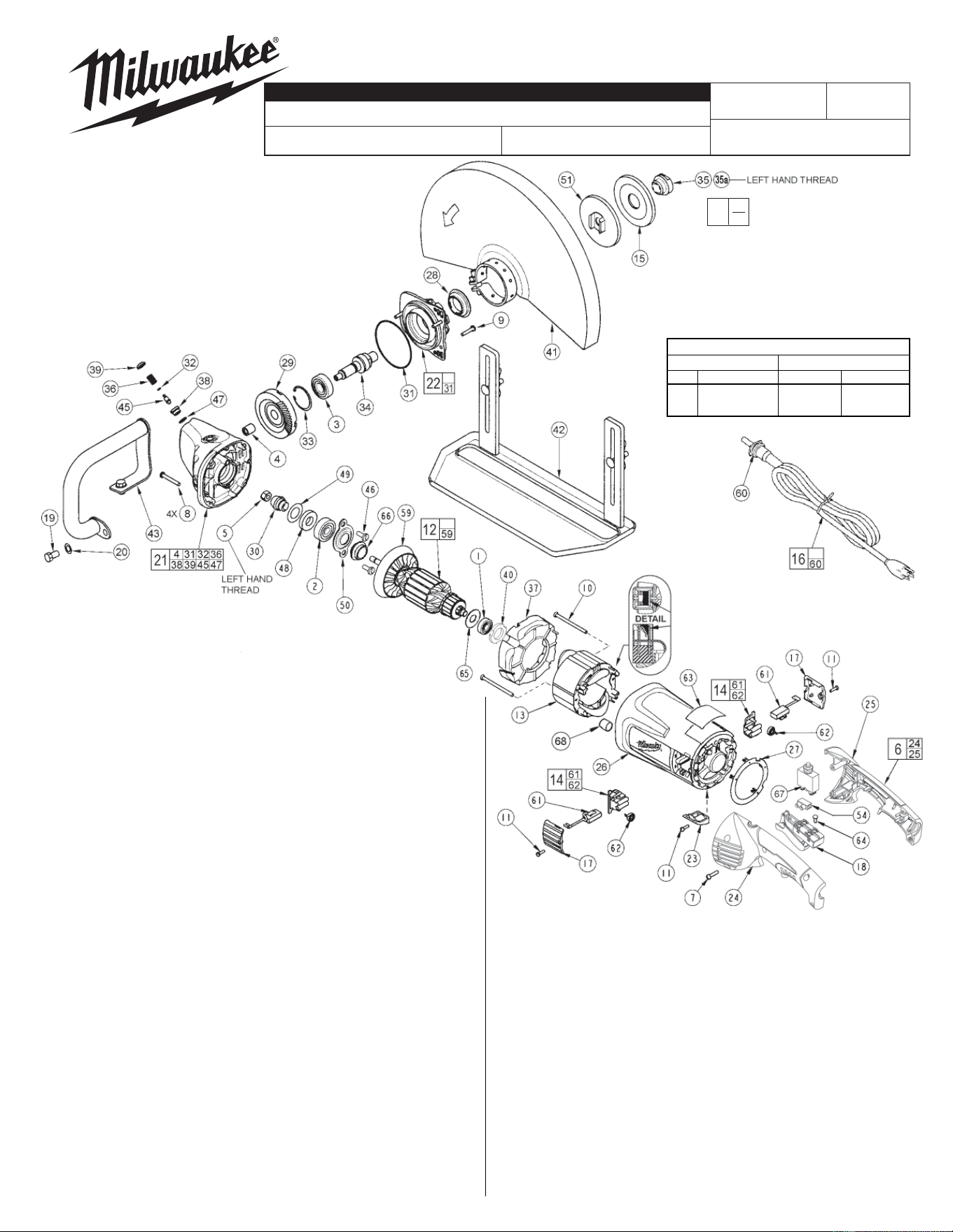
6185-20
FIG. PART NO. DESCRIPTION OF PART NO REQ.
1 02-04-1675 Ball Bearing (1)
2 02-04-1680 Ball Bearing (1)
3 02-04-1745 Ball Bearing (1)
4 02-50-2429 Needle Bearing (1)
5 06-55-2460 Hex Nut - Left Hand Thread (1)
6 14-34-0566 Handle Kit (1)
7 06-82-0055 8-16 Torx Plastite Screw T-20 (5)
8 06-82-0060 10-14 Torx Plastite Screw T-25 (4)
9 06-82-0065 10-32 x 1 Pan Hd. Taptite T-25 Screw (3)
10 06-82-7435 8-16 x 3-3/64" Pan Hd. Plastite Screw T-20 (2)
11 06-82-7240 6-19 x 1/2 Slt. Pan Hd. Plast. T-15 (3)
12 16-70-7135 Armature Assembly (1)
13 18-70-7135 Field (1)
14 22-20-0120 Brush Holder Assembly (2)
15 43-34-0845 Outer Flange (1)
16 22-64-1206 Cord Set (Incl. Cord Protector & Terminals) (1)
17 23-44-0255 Brush Cover (2)
18 23-66-2726 Switch (1)
19 06-75-0494 3/8-16 Hex Hd. Bolt (2)
20 06-97-0070 3/8 Split Ring Lock Washer (2)
21 28-14-1136 Gearcase Kit (1)
22 28-53-0301 Spindle Hub Kit (1)
23 31-15-0166 Cover (1)
24 --------------- Left Hand Handle Halve (1)
25 --------------- Right Hand Handle Halve (1)
26 31-50-1785 Motor Housing (1)
27 31-53-0161 Plug (1)
28 31-55-0150 Bearing Shield (1)
29 32-05-1530 Gear (1)
30 32-60-1530 Pinion Gear (1)
31 34-40-0505 O-Ring (1)
32 --------------- O-Ring (1)
33 34-80-2960 Retaining Ring (1)
34 38-50-1520 Spindle Shaft (See Note) (1)
35 44-40-0815 1.0" Flange Nut - Left Hand Thread (1)
35a 44-40-0820 20mm L.H. Flange Nut (1)
36 --------------- Compression Spring (1)
37 42-14-0425 Baffl e (1)
38 --------------- Lock Body (1)
39 --------------- Button (1)
40 45-06-1000 Dust Seal (1)
41 43-54-1510 Guard Assembly (1)
42 43-40-0415 Shoe Assembly (1)
43 43-62-1510 Handle Assembly (1)
45 --------------- Lock Pin (1)
46 06-75-0510 1/4-20 x .625 Hex Flange Screw (2)
47 --------------- O-Ring (1)
48 45-06-0710 Seal (1)
49 45-88-7880 Shim Washer (1)
50 44-86-0040 Bearing Retainer (1)
14" ABRASIVE CUT-OFF MACHINE
Nov. 2013
REVISED BULLETIN
54-40-0641
SERVICE PARTS LIST
BULLETIN NO.
WIRING INSTRUCTION
DATE
SPECIFY CATALOG NO. AND SERIAL NO. WHEN ORDERING PARTS
SERIAL
NUMBER
CATALOG NO.
MILWAUKEE ELECTRIC TOOL CORPORATION
13135 W. LISBON RD., BROOKFIELD, WI 53005
Drwg. 2
FIG. LUBRICATION:
21 1.25 oz. (35 grams) of Type "Y" grease,
No. 49-08-5270 in main gear cavity of gearcase.
29,30 "Y" grease must be applied to all gear teeth.
31,32 Lightly coat o-rings with "Y" grease prior to
installation.
FIG. PART NO. DESCRIPTION OF PART NO REQ.
51 43-34-0850 Inner Flange (1)
54 22-56-0480 Terminal Block (1)
59 22-84-0540 Fan Assembly (1)
60 --------------- Cord Protector (1)
61 22-18-0126 Carbon Brush Assembly (2)
62 --------------- Brush Spring (2)
63 12-99-5010 Nameplate Blank (1)
64 05-78-0305 Switch Screw (4)
65 23-86-0160 Dust Seal (1)
66 31-55-0290 Dust Shield (1)
67 22-36-0350 Breaker (1)
68 23-82-0360 Heat Shrink Tube (4)
49-96-0380 Hex Wrench (Not Shown) (1)
23-94-9300 Leadwire Assembly - Red (Not Shown) (1)
23-94-9305 Leadwire Assembly - White (Not Shown) (1)
23-94-9314 Leadwire Assembly - White (Not Shown) (1)
23-94-5091 Leadwire Assembly - Black (Not Shown) (1)
23-94-5096 Leadwire Assembly - Black (Not Shown) (1)
23-94-5650 Ground Wire Assembly - Green (Not Shown) (1)
10-98-6085 Warning Label - French and Spanish (1)
00
EXAMPLE:
Component Parts (Small #)
Are Included When Ordering
The Assembly (Large #).
0
Fig. nos. 49, 48 and 2 are to be assembled into gearcase
bearing pocket and held in place with fi g. nos. 46 and
50, as shown. Slide armature shaft through bearing,
dust shield (#66), and fi g. no. 30 (inside gearcase)
and fasten to specifi ed torque with left hand
hex nut, fi g. no. 5.
FIG. NOTES:
4,21 Press needle bearing +.01 to +.04
to gearcase boss face.
33 Bevel side of retaining ring away
from bearing face.
TORQUE CHART
Seating Torque
Fig. Part No. Minimum Maximum
5 06-55-2460 150 160
46 06-75-0510 65 75
FIELD TERMINAL POCKETS
Fill cavities with Type 'X' contact grease
No. 49-08-5000, 4 places.
Do not over fi ll and allow grease to extend
past edges.