MILWAUKEE ELECTRIC TOOL CORPORATION
13135 W. Lisbon Road., Brookfi eld, WI 53005
Drwg. 4
BULLETIN NO.
54-40-0675
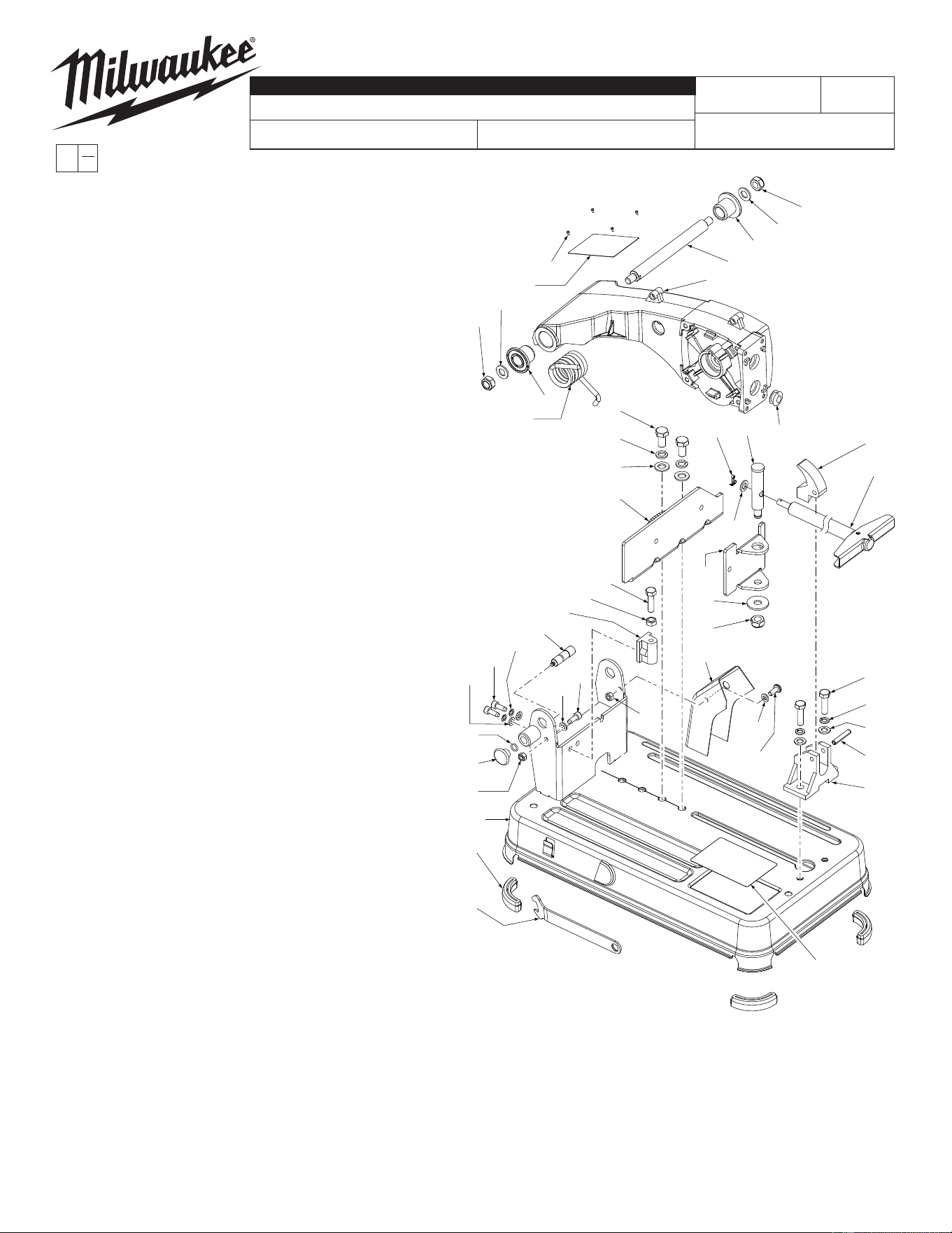
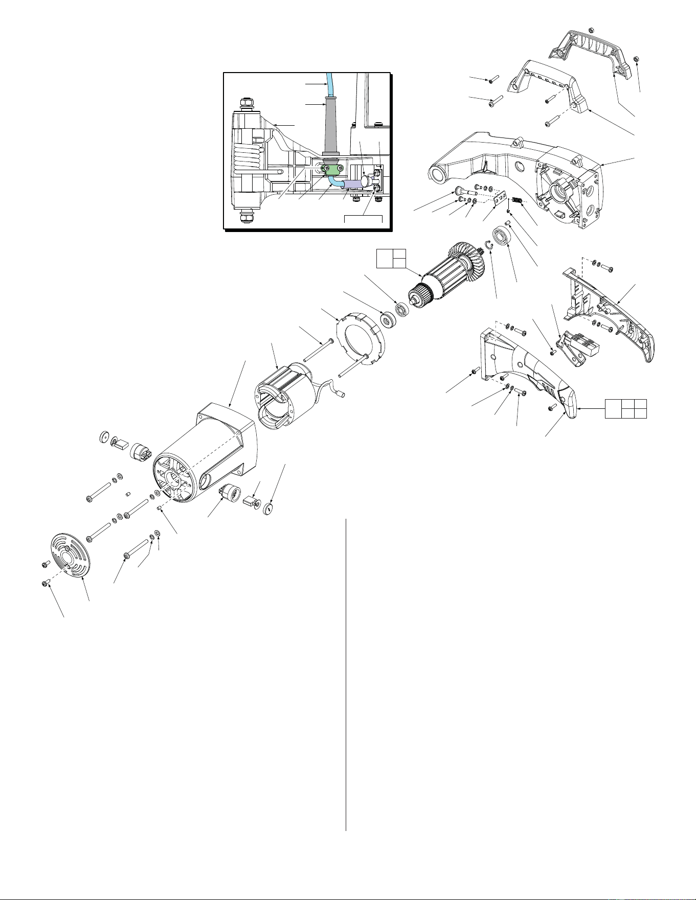
SERVICE PARTS LIST
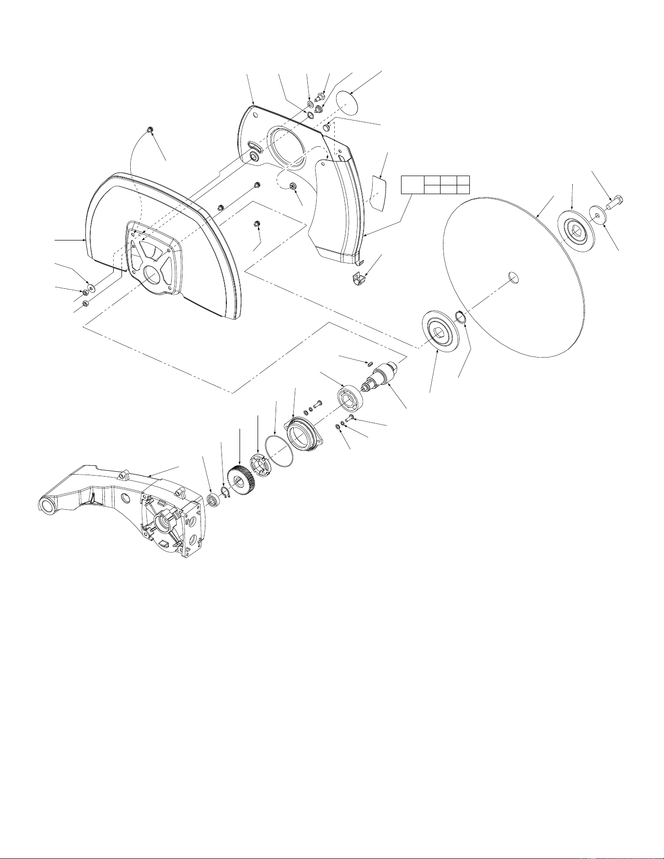
EXAMPLE:
Component Parts (Small #) Are Included
When Ordering The Assembly (Large #).
0
00
CATALOG NO. 6177-20
REVISED BULLETIN
SPECIFY CATALOG NO. AND SERIAL NO. WHEN ORDERING PARTS
14" ABRASIVE CUT-OFF MACHINE
STARTING
SERIAL NO.
DATE
Feb. 2013
WIRING INSTRUCTION
58-01-0552
C77A
FIG. PART NO. DESCRIPTION OF PART NO REQ.
1 05-75-0065 M10 x 17 Hex Bolt (2)
23 28-50-0020 Upper Arm (1)
41 44-76-0104 Grommet (1)
50 45-88-8495 6mm Flat Washer (4)
51 05-90-0185 6mm Spring Waher (2)
69 42-12-0425 Shaft (1)
70 45-88-8905 10mm Flat Washer (3)
71 05-90-0205 10mm Spring Washer (2)
72 05-55-0135 M10 Nut (2)
76 45-84-0130 Rear Vise (1)
78 05-86-0800 M8 x 13 Bolt (3)
79 05-55-0140 M8 Hex Nut (1)
80 42-30-0415 Stopper Body (1)
81 45-96-0100 Wrench (1)
82 42-42-0465 Lock Button (1)
83 34-40-0091 O-Ring (1)
85 44-50-0175 Lock Down Pin (1)
86 05-55-0125 M6 Nut (2)
88 05-74-0745 M6 x 16 Bolt (4)
89 45-22-0690 Sleeve (2)
90 43-54-0910 Spark Guard (1)
91 40-50-1295 Torsion Spring (1)
96 06-65-0017 Cotter Pin (1)
97 44-64-0020 Vise Shaft (1)
98 45-84-0135 Clamp Fence (1)
99 45-88-8421 10mm Flat Washer (1)
100 05-55-0145 M8 Nylon Hex Nut (1)
101 05-90-0210 8mm Spring Washer (2)
102 45-88-8915 8mm Flat Washer (2)
103 44-40-0016 Release Nut (1)
104 06-65-0019 Roll Pin (1)
105 45-07-0010 Seat (1)
106 45-84-0140 Screw Bar Assembly (1)
109 31-06-0016 Base (1)
110 44-34-0018 Rubber Foot (3)
117 12-20-6177 Service Nameplate (1)
118 06-72-1720 Nameplate Rivet (4)
119 10-20-7300 Warning Label (1)
72
70
91
89
23
118
117
72
69
89
70
83
82
86
109
110
81
50
51
78
79
80
85
50
88
86
88
1
71
102
76
41
98
99
100
90
50
88
78
101
102
104
105
103
106
119
70
96 97
34 64 62 112
68 67
87,15,16
BOTTOM VIEW OF ARM (23)
28
26
27
23
30
38
39
25
24
68
87
15
16
67
56
57
52
51
50
58
47
48
43
59
45
49
53
54
55
35
36
16
32
60
15
31
65
66
61
62
63
23
29
30 35
36
95
32
46
FIG. PART NO. DESCRIPTION OF PART NO REQ.
15 05-90-0190 5mm Spring Washer (6)
16 45-88-8485 5mm Flat Washer (6)
23 28-50-0020 Upper Arm (1)
24 05-81-0811 M5 x 13 Pan Hd. Plast. Screw (2)
25 05-81-0776 M4 x 16 Pan Hd. Plast. ST Screw (2)
26 31-44-3220 Carrying Handle - Right (1)
27 31-44-3225 Carrying Handle - Left (1)
28 05-55-0030 M5 Hex Nut (2)
30 31-44-3230 Handle - Right (1)
31 05-81-0522 M5 x 20 Pan Hd. Screw (4)
32 --------------- Retaining Ring (1)
34 05-81-0432 M4 x 13 Pan Hd. Screw (2)
35 05-78-0428 M4 x 16 Pan Hd. Plast. ST Screw (3)
36 31-44-3235 Handle - Left (1)
38 05-78-0427 M4 x 10 Pan Hd. Plast. ST Screw (1)
39 23-66-1425 Switch (1)
FIG. PART NO. DESCRIPTION OF PART NO REQ.
43 31-05-0016 Baffl e (1)
45 18-82-0100 120 V Field (1)
46 16-82-0200 120 V Armature (1)
47 02-04-0016 Ball Bearing (1)
48 45-22-0725 Bearing Sleeve (1)
49 31-50-0025 Motor Housing (1)
50 45-89-8495 6mm Flat Washer (4)
51 05-90-0185 6mm Spring Washer (4)
52 05-81-0521 M6 x 60 Pan Hd. Screw (4)
53 22-20-0017 Brush Holder (2)
54 22-16-0036 120 V Brush (2)
55 22-24-0027 Brush Cap (2)
56 05-81-0476 M5 x 13 ST Screw (2)
57 31-15-0515 End Cap (1)
58 05-81-0495 M5 x 8 Set Screw (2)
59 05-81-0681 M5 x 80 ST Screw (2)
60 02-04-0026 Ball Bearing (1)
61 44-60-1900 Rubber Pin (1)
62 22-64-1422 120V Power Cord (1)
63 44-76-0061 Cord Protector (1)
64 42-68-0910 Cord Clamp (1)
65 40-50-0136 Lock Pin Spring (1)
66 34-60-0015 Retaining Ring (1)
67 42-36-0056 Plate (1)
68 44-60-0061 Lock Pin Assembly (1)
87 05-81-0431 M5 x 10 Screw (2)
95 14-46-3200 Operating Handle Kit (1)
112 23-48-0105 Insulation Sleeve (1)
22
21
20
19
18
17
16
15
14
13
12
11
3
113
4
3
1
2
23
10
92
86
7 111 6 5 93 121
8
120
8
114
94
(3x)
(1x)
7 8 94
120 121
122
9
FIG. PART NO. DESCRIPTION OF PART NO REQ.
1 05-75-0065 M10 x 17 Hex Bolt (1)
2 45-88-0016 Special Washer (1)
3 43-34-0905 Wheel Flange (Inner and Outer) (2)
4 --------------- Abrasive Cutting Wheel (1)
5 05-89-0065 M6 Hex Shoulder Bolt (1)
6 45-88-8900 Hard Paper Washer (1)
7 --------------- Lower Guard (1)
8 42-38-0435 Rubber Bumper (2)
9 05-81-0442 M6 x 10 Sems Screw (3)
10 43-54-0905 Upper Guard (1)
11 38-50-0056 Spindle (1)
12 05-42-0016 4 x 4 x 12 Key (1)
13 02-04-0046 Ball Bearing (1)
14 05-81-0120 M5 x 20 Pan Hd. Screw (2)
15 05-90-0190 5mm Spring Washer (2)
16 45-88-8485 5mm Flat Washer (2)
17 43-34-0900 Bearing Flange (1)
18 34-40-0090 O-Ring (1)
19 42-74-0063 Wheel Lock (1)
20 32-75-0016 Gear (1)
21 05-92-0056 Retaining Ring (1)
22 02-04-0036 Ball Bearing (1)
23 28-50-0020 Upper Arm (1)
86 05-55-0125 M6 Nut (2)
92 45-88-8910 M6 Special Washer (Flat) (1)
93 05-89-0080 M6 Shoulder Screw (1)
94 42-52-0040 Lower Guard Cap (1)
111 45-88-8925 Washer (1)
113 34-60-0018 Retaining Ring (1)
114 05-81-0441 M6 x 18 Sems Screw (1)
120 10-20-7301 Lower Guard Label (1)
121 10-15-6176 Round Lower Guard Label (1)
122 43-54-0901 Lower Guard Assembly (1)
49-08-5270 Type 'Y' Grease (6 oz. Tube) (1)
(23-27 grams, approx. 7/8 oz. needed)