INSTRUCTION MANUAL
LED WATERPROOF FITTING WITH MICROWAVE SENSOR
STAINLESS
CLIPS
MULTI-LANGUAGE
MANUAL QR CODE
Please scan the QR code
to access the manual in
multiple languages.
MODEL
SKU
LUMENS
WATTS
DIMENSION
BEAM ANGLE
INPUT VOLTAGE
VT-120137S
24013, 24016
4320 lm
36W
1200x78x72mm
120°
AC:200~240V, 50/60Hz
SWITCHING CAPACITY
STAND-BY POWER
DETECTION AREA
HOLD TIME
Max,100W
≤0.5W
50%/100%
5s/1min/3min/10min
1. Please make sure to turn o the power before starting the installation.
2. Installation must be performed by a qualified electrician.
3. The light source of this luminaire is not replaceable; when the light source reaches its end of life the
whole luminaire shall be replaced.
4. If the external flexible cable or cord of this luminaire is damaged, it shall be exclusively replaced by
the manufacturer or his service agent or a similar qualified person in order to avoid a hazard.
5. Must be connected to waterproof terminal box.
6. For indoor use and outdoor use.
WARNING
INTRODUCTION & WARRRANTY
SENSOR TECHNICAL DATA
TECHNICAL DATA
Thank you for selecting and buying V-TAC product. V-TAC will serve you the best. Please read these instructions carefully before starting the installation
and keep this manual handy for future reference. If you have any another query, please contact our dealer or local vendor from whom you have purchased
the product. They are trained and ready to serve you at the best. The warranty is valid for 2 years from the date of purchase. The warranty does not apply
to damage caused by incorrect installation or abnormal wear and tear. The company gives no warranty against damage to any surface due to incorrect
removal and installation of the product. The products are suitable for 10-12 Hours Daily operation. Usage of product for 24 Hours a day would void the
warranty. This product is warranted for manufacturing defects only.
LIFE SPAN
ON/OFF CYCLE
CRI
DF
P
sb
MATERIAL
MAX. CONNECTABLE UNITS
20,000 Hours
10,000 Times
≥80
≥0.9
≤0.5W
PC+PC
10
DAYLIGHT THRESHOLD
MICROWAVE FREQUENCY
MICROWAVE POWER
MOUNTING HEIGHT
30Lux/Disable
5.8GHz±75MHz
<0.3mW
DETECTION RANGE
OPERATING TEMPERATURE
MOTION DETECTION
-25°C TO +60°C
0.5~1.5M/S
(ceiling mounted)
(ceiling mounted)
2.5-4m/8.2-13.12
ø4-10m/13.12-32.8
Non-replaceable
control gear
Non-replaceable
light source
This marking indicates that this
product should not be disposed
of with other household wastes.
Caution, risk of electric shock.
VT-150149S
24015, 24017
5760 lm
48W
1500x78x72mm
IN CASE OF ANY QUERY/ISSUE WITH THE PRODUCT, PLEASE REACH OUT TO US AT: SUPPORT@V-TAC.EU
FOR MORE PRODUCTS RANGE, INQUIRY PLEASE CONTACT OUR DISTRIBUTOR OR NEAREST DEALERS.
V-TAC EUROPE LTD. BULGARIA, PLOVDIV 4000, BUL.L.KARAVELOW 9B
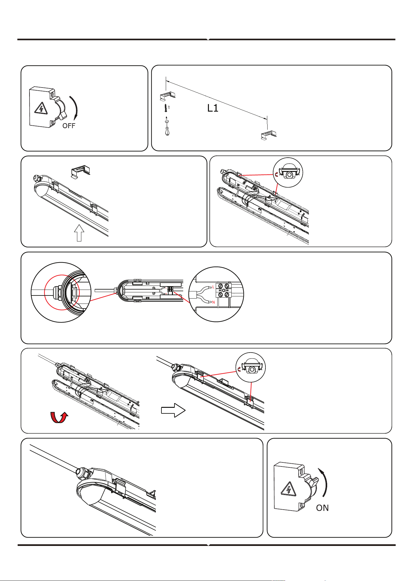
SINGLE UNIT INSTALLATION INSTRUCTIONS
STEP 8:
Switch ON
the power
to test the
light.
STEP 7: Wire the
water-proof fitting to
the main power
supply. Ensure to use
waterproof terminal
block [not included].
STEP 6: Install the diuser
to the waterproof fitting
and close the clips.
STEP 4: Open the
side clips of
waterproof fitting
and open the
diuser as shown
in the diagram.
STEP 2: Fix the mounting
brackets onto the ceiling
using screws and expan-
sion plug(included). Please
refer to table for installing
the mounting bracket
distance points.
STEP 1: Switch
OFF the power
before starting
the installation.
STEP 3: Mount
water-proof lamp
onto the mounting
brackets.
STEP 5: Fasten the waterproof connector
clockwise from the first end and insert the
cable through the waterproof connector and
wire into the terminal block from one end
[L(Live) & N(Neutral)] and wire the sensor into
other side or terminal block. Wiring must
done according to the schematic diagram.
WATERPROOF CONNECTOR
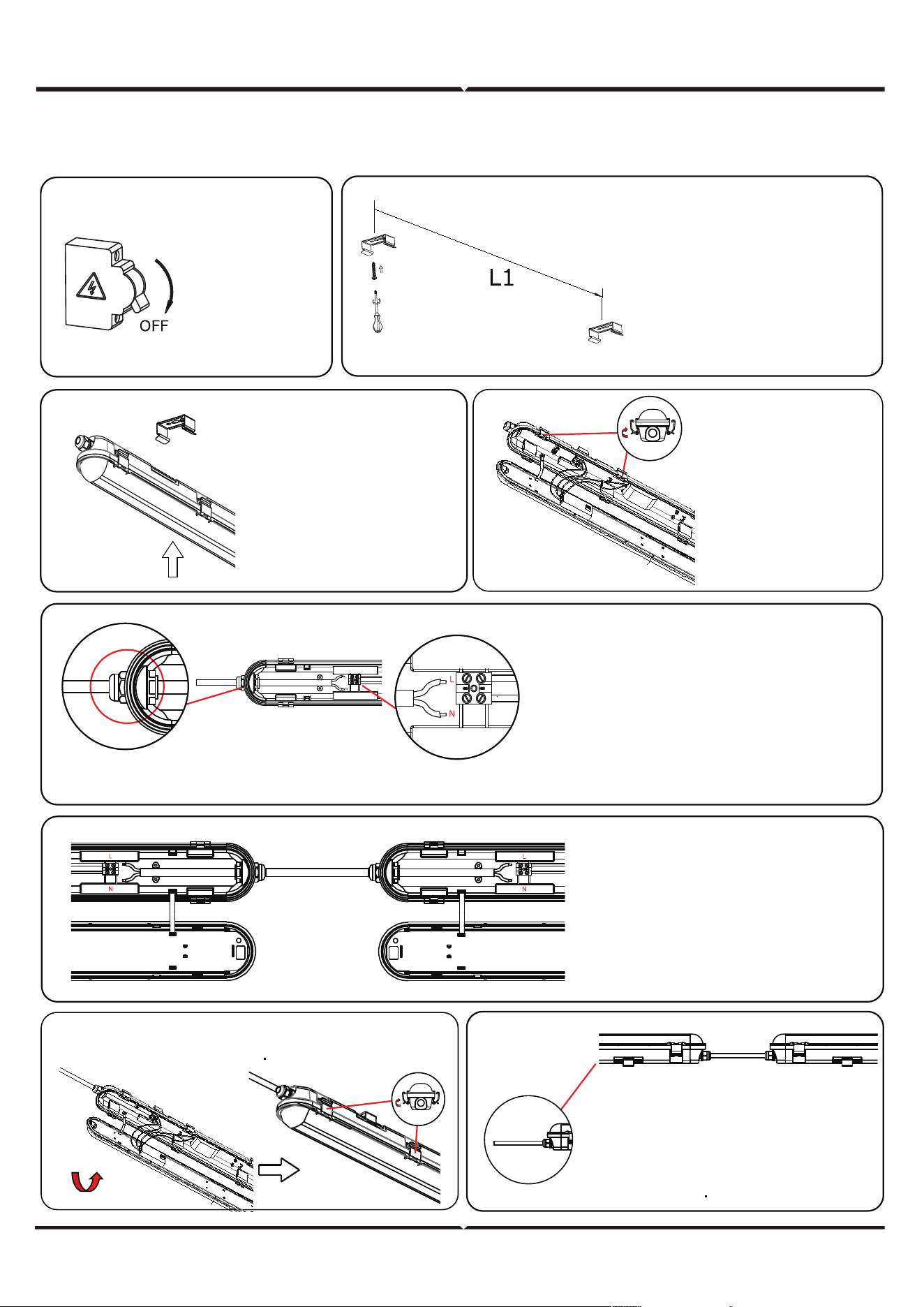
MULTIPLE (LINKABLE) UNITS INSTALLATION INSTRUCTIONS
Note: Please refer to the model number and max linkable units which can be linked together. Based on the max linkable units select the max
waterproof fittings which you would like to connect.
WATERPROOF CONNECTOR
WATERPROOF
END WIRE
STEP 5: Wiring 1st waterproof fitting from both
the ends - Fasten the waterproof connector
clockwise from the first end and insert the
cable through the waterproof connector and
wire into the terminal block from one end
[L(Live) & N(Neutral)] and wire the sensor into
other side or terminal block. Wiring must done
according to the schematic diagram.
STEP 6: Fasten the waterproof
connector from other end of the
waterproof fitting and insert the
wire into the terminal block.
Using the same cable fasten the
waterproof connector of the 2nd
waterproof fitting and wire into
the terminal block.
STEP 8: Wire the waterproof fitting to
the main power supply.
Ensure to use waterproof terminal
block [not included].
STEP 9: Switch ON the power to test
the light.
STEP 7: Install the diuser to the waterproof fitting and
close the clips.
STEP 2: Fix the mounting
brackets onto the ceiling
using screws and expansion
plug(included). Please refer
to table for installing the
mounting bracket distance
points.
STEP 3: Mount
water proof lamp
onto the mounting
brackets.
STEP 4: Open the side
clips of waterproof
fitting and open the
diuser as shown in
the diagram.
STEP 1: Switch
OFF the power
before starting
the installation.

Switch UP
Switch DOWN
Daylight Threshold
Hold-Time
Detection Area
Disable
SENSOR CONFIGURATION
1. AUTOMATICALLY ON/OFF FUNCTION
SENSOR SETTINGS
DETECTION AREA HOLD-TIME DAYLIGHT THRESHOLD
In this area, movement will be
detected and able to trigger
the sensor. 100% detection
area is also known as the
strong sensitvity.
Light on when detect movement and o aer people leave at night.
Applications: Corridor, Staircase.
With sucient daylight, even
when motion detected, light
remains OFF.
With insucient daylight,
when motion detected,
light ON.
Aer the last detection and the
present hold time elapsed,
light OFF.
The period of light keeping
100% brightness aer
moving objects leave the
detection area.
Definition of the ambient
brightness; only when the
ambient brightness is lower than
the preset specific lux amount,
the sensor will work; when it's
preset as "disable",the sensor
works everytime it detects
motion regardless the ambient
brightness.
Hold time
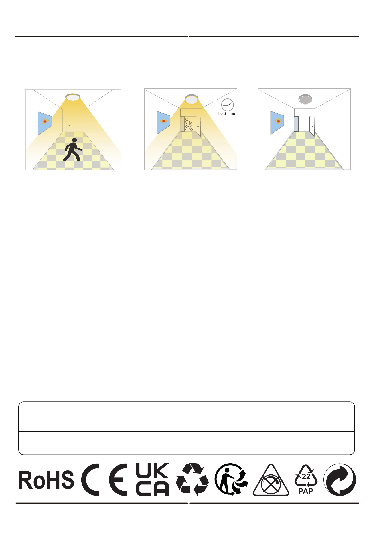
2. NO DAYLIGHT FUNCTION
USER NOTES
The daylight threshold is set to "Disable".
Light on when detect movement, Aer people leave, Light o aer hold on time.
Applications: Dim places such as Basement Parking, Underpass.
1. Microwave can penetrate walls or glass thinner than 20cm and attenuate if thicker than 20cm.
2. The driver voltage shall be stable and float within 10%.
3. Detection area will be aected by speed of motion, mounting height and movement volume.
4. Conduct test on sunny days without the lampshade which will aect the tested lux value
When motion is detected,
the sensor will switch on the
light to 100% brighteness.
Aer people leave the
detection area, light
remains 100% brightness
within hold time.
Aer the last detection
and the present hold
time elapsed, light OFF.
V-TAC UK LTD. IN CASE OF ANY QUERY/ISSUE WITH THE PRODUCT PLEASE REACH OUT TO US AT
[email protected] V-TAC, 5A TUNGSTEN PARK, DOWNS ROAD, WITNEY, OXFORDSHIRE, OX29 0AX
V-TAC WEST EUROPE LTD. IN CASE OF ANY QUERY/ISSUE WITH THE PRODUCT, PLEASE REACH OUT TO US AT:
[email protected] FOR MORE PRODUCTS RANGE, INQUIRY PLEASE CONTACT OUR DISTRIBUTOR OR NEAREST DEALERS.
V-TAC WEST EUROPE LTD. GROUND FLOOR, 71 LOWER BAGGOT STREET, DUBLIN 02, IRELAND DO2 P593