

OPERATOR’S MANUAL
OSCILLATING EDGE BELT/SPINDLE SANDER
R4840
Your saw has been engineered and manufactured to our high standard for dependability, ease of operation, and operator
safety. When properly cared for, it will give you years of rugged, trouble-free performance.
WARNING:
To reduce the risk of injury, the user must read and understand the operator’s manual before using this product.
SAVE THIS MANUAL FOR FUTURE REFERENCE

2
FUNCTIONAL DESCRIPTION ...........................................2
FEATURES
........................................................................3
IMPORTANT SAFETY INSTRUCTIONS
.............................4
SAFETY SYMBOLS-DEFINITIONS
....................................5
GENERAL SAFETY RULES
.................................................6
SANDER SAFETY RULES
....................................................7
WHEN INSTALLING OR MOVING THE SANDER .................... 7
BEFORE EACH USE ...........................................................7
PLAN AHEAD TO PROTECT YOUR EYES, HANDS, FACE
AND EARS ........................................................................7
WHEN SANDER IS RUNNING .............................................8
BEFORE LEAVING THE SANDER .........................................8
PROPOSITION 65 WARNING:
.........................................9
PRECAUTIONS TO TAKE WHEN SANDING METALS
.........9
PRECAUTIONS TO TAKE WHEN SANDING PAINT
............9
MOTOR SPECIFICATIONS AND ELECTRICAL
REQUIREMENTS
........................................................... 10
POWER SUPPLY AND MOTOR SPECIFICATIONS.................10
110-120 VOLT, 60 HZ. TOOL INFORMATION .....................10
MOTOR SAFETY PROTECTION .........................................11
EXTENSION CORDS ........................................................11
UNPACKING AND CHECKING CONTENTS
..................... 12
PACKAGE CONTENTS DESCRIPTION ................................12
CONTENTS OF HARDWARE BAGS ....................................13
TOOLS NEEDED FOR ASSEMBLY OR ADJUSTMENTS ..........13
ASSEMBLY
.................................................................... 14
INSTALLING THE SANDING BELT ASSEMBLY ..................... 14
REMOVING THE SANDING BELT ASSEMBLY ......................14
INSTALLING SANDING SLEEVES LARGER THAN
1/2 INCH DIAMETER ....................................................... 15
INSTALLING 1/2 INCH DIAMETER SANDING SLEEVE ......... 16
SELECTION OF SPACER RING INSERTS AND
UPPER SPINDLE WASHERS .............................................. 16
BOLTING OSCILLATING EDGE BELT/SPINDLE
SANDER TO WORKBENCH ...............................................17
CLAMPING OSCILLATING EDGE BELT/SPINDLE
SANDER TO WORKBENCH ...............................................17
MAKING ADJUSTMENTS
............................................... 18
SQUARING FRONT TABLE ................................................18
ALIGNING BELT TO MITER GAUGE SLOT ..........................18
REMOVING/INSTALLING THE SANDING BELT ...................19
OPERATION
.................................................................. 19
ON-OFF SWITCH ............................................................20
ON-OFF SWITCH PADLOCK FEATURE ...............................20
SANDPAPER SELECTION..................................................21
SURFACE SANDING ON THE SANDING BELT .....................21
END SANDING ON THE SANDING BELT ............................22
SANDING CURVED EDGES ...............................................22
FEED DIRECTION ...........................................................22
DUST COLLECTION CAPABILITY ......................................23
TRANSPORTING SANDER ................................................23
MAINTENANCE
............................................................. 24
KEEP MACHINE CLEAN .................................................... 24
MAINTENANCE REMINDERS ............................................24
ACCESSORIES
............................................................... 24
TROUBLESHOOTING
..................................................... 25
WARRANTY
................................................................... 27
TABLE OF CONTENTS
FUNCTIONAL DESCRIPTION
SPECIFICATIONS
The RIDGID® #R4840 OSCILLATING EDGE BELT/SPINDLE
SANDER is designed for portability and high quality performance.
It includes: machine equipped with a 6-amp motor, sturdy tubular
frame, a beveling work table, 2 1/2 inch dust port, work rest
attachment, two wrenches, one belt sander attachment (tted
with a 4 x 24 inch sanding sleeve), four spacer ring inserts, four
washers, four rubber drums, and ve sanding sleeves (1/2 inch,
3/4 inch, 1 inch, 1 1/2 inch and 2 inch).
NOTICE: The manual cover illustrates the current production
model. All other illustrations contained in the manual are
representative only and may not be exact depictions of the actual
labeling or accessories included. They are intended for illustrative
purposes only.
Sanding Sleeves: 1/2, 3/4, 1, 1 1/2, 2 inch
Sanding Drums: 3/4, 1, 1 1/2, 2 inch
Sanding Belt: 4 x 24 inches
Oscillations: 57.5/minute
Stroke: 7/8 inch
Overall Weight: 45 Lbs.
MOTOR SPECIFICATIONS:
Amps 6 Amps
Voltage 120 volts
3
Parts Storage
Storage for the sanding belt assembly and table insert is provided
by the brack on the rear of the base.
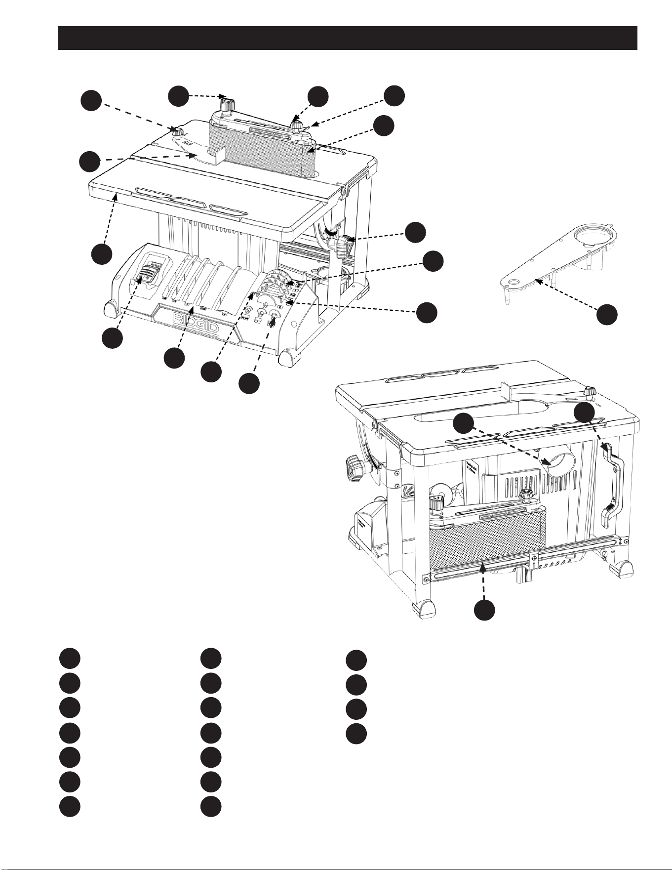
FEATURES
F7
F8
F9
F10
Washers
2.5mm Hex Wrench
Sanding Drum/Sleeves
On/O Switch
Work Table
Work Rest
Work Rest Knob
F11
F14
F16
F12
F17
F13
F15
F18
F5
F6
F1
F2
F3
F4
Spindle Knob
Tracking Knob
Belt Tension Lever
Sanding Belt
Front Table Lock Knob
Spacer Ring Inserts
T25 Torx Wrench
F6
F8
F10
F11
F13
F12
F14
F15
F1
F5
F3
F4
F16
F18
F17
F2
F9
F7
Table Insert
Dust Collection Port
Cord Wrap
Table Insert/Sanding
Belt Storage

4
IMPORTANT SAFETY INSTRUCTIONS
If you have any questions or concerns regarding the use of your tool or the contents of this manual, please stop using the tool and
contact Customer Service, at RIDGID
® Portable and Fixed Power Tool Technical Service at (toll free) 1-888-359-4778.
CAREFULLY READ AND FOLLOW ALL WARNINGS AND INSTRUCTIONS ON YOUR PRODUCT
AND IN THIS MANUAL. SAVE THIS MANUAL. MAKE SURE ALL USERS ARE FAMILIAR WITH ITS WARNINGS
AND INSTRUCTIONS WHEN USING THE TOOL. Improper operation, maintenance or modification of tools or
equipment could result in serious injury and/or property damage.
1. Spindle Knob: Loosen knob to remove sanding belt assembly
(or sanding drum) and change to spindle sanding (or belt
sanding). NOTE: Knob has left hand threads. Turn knob
clockwise to loosen and counterclockwise to tighten.
2. Tracking Knob: Turning the knob clockwise will allow the
sanding belt to slide up on the assembly. Turning the knob
counterclockwise will allow the sanding belt to slide down on the
assembly.
3. Belt Tension Lever: Slide lever left to release the sanding belt
tension; slide right to apply belt tension.
4. Sanding Belt: Removes material from wood. Oscillates (7/8
inch) up and down to sand faster and prevents burning of the
workpiece.
5. Front Table Lock Knob: Loosening knob allows the front table
to be tilted for bevel sanding or storage.
6. Spacer Ring Inserts: Fits around drum to help support
workpiece.
7. T25 Torx Wrench: Used for aligning the belt to miter gauge slot
(If needed).
8. Washers: Used to securely fasten the Spindle Knob to the
machine without damaging the Sanding Sleeves or Drums.
9. 2.5mm hex wrench: Used for leveling the table insert and
squaring the front table (If these adjustments are needed).
10. Sanding Drum(s)/Sleeve(s): Removes material from wood.
Oscillates up and down to sand faster and prevents burning the
workpiece.
11. On-Off Switch: Turns the machine on and off. Can be locked
with a simple padlock when not being used.
12. Work Table: Supports the workpiece. Can also be tilted for bevel
sanding.
13. Work Rest: The work rest ensures the material is perpendicular
to the sanding belt.
14. Work Rest Knob: This knob is used to tighten the Work Rest in
its position.
15. Dust Collection Port: 2.5 inch opening for wet/dry vac hook-up.
16. Table Insert: Helps to support workpiece when drum sanding.
17. Table Insert/Sanding Belt Storage: Holds table insert or
sanding belt when not being used.
FEATURES

5
SAFETY SYMBOLS-DEFINITIONS
Safety is a combination of common sense, staying alert and
knowing how your oscillating edge belt/spindle sander works.
Read this manual to understand this sander. Safety Signal Words
It is important for you to read and understand this manual. The
information it contains relates to protecting YOUR SAFETY and
PREVENTING PROBLEMS. The symbols below are used to help
you recognize this information.
Indicates an imminently hazardous situation
which, if not avoided, will result in death or serious injury.
Indicates a potentially hazardous situation which,
if not avoided, could result in death or serious injury.
Indicates a potentially haz ard ous situation which,
if not avoided, may result in minor or mod er ate injury.
NOTICE
AVIS
AVISO
fr
sp
Indicates a practice not related to personal
injury which, if not avoided, may result in property damage.
Before Using The Sander:
Your risk from these exposures varies, depending on how often
you do this type of work. To reduce your exposure to these
chemicals:
Work in a well ventilated area, and work with approved safety
equipment, such as those dust masks that are specially designed
to filter out microscopic particles.
To reduce the risk of mistakes that could cause
serious, permanent injury, do not plug the sander in until the
following steps are completed:
• Assembly. (See pages 13-17)
• Learn the use and function of the ON-OFF switch. (See page
20)
• Review and understanding of all safety instructions and
operating procedures in this manual.
• Review of the maintenance methods for this sander. (See
page 24)
Some of the following symbols may be used on the tool. Please study them and learn their meaning. Proper interpretation on these symbols
will allow you to operate the tool better and safer.
SYMBOL NAME DESIGNATION/EXPLANATION
Safety Alert Indicates a potential personal injury hazard.
Read Operator's Manual
To reduce the risk of injury, user must read and understand operator's manual before using this
product.
Eye Protection Always wear eye protection with side shields marked to comply with ANSI Z87.1.
No Hands Symbol Failure to keep your hands away from the blade will result in serious personal injury.
Wet Conditions Alert Do not expose to rain or use in damp locations.
Pinch Warning Always watch for movement paying extra attention to potential areas where pinching could occur.
V Volts Voltage
A Amperes Current
Hz Hertz Frequency (cycles per second)
min Minutes Time
~/AC Alternating Current Type of current
ⁿ
₀
No Load Speed Rotational speed, at no load
.../min Per Minute Revolutions, strokes, surface speed, orbits, etc., per minute
Lbs Pounds Unit of weight
Kg Kilograms Unit of weight
RPM Revolutions Per Minute Speed of rotation of machine
PH:1 Phase 1 This is a 1 phase motor
Double Insulation
To reduce the risk of electric shock, some machines have a polarized plug (one blade is wider than the other). This
plug will t in a polarized outlet only one way. If the plug does not t fully in the outlet, reverse the plug. If it still
does not t, contact a qualied electrician to install the proper outlet. DO NOT change the plug in any way.

6
1. For your own safety, read the instruction manual before
operating the machine. Learning the machine’s application,
limitations, and specific hazards will greatly minimize the
possibility of accidents and injury.
2. ALWAYS USE SAFETY GLASSES. Also use face or dust
mask if cutting operation is dusty. Everyday eyeglasses
only have impact resistant lenses, they are NOT safety glasses.
Use certified safety equipment. Eye protection equipment should
comply with ANSI Z87.1 standards. Hearing equipment should
comply with ANSI S3.19 standards.
3. Wear proper apparel. Do not wear loose clothing, gloves,
neckties, rings, bracelets, or other jewelry which may get caught
in moving parts. Nonslip protective footwear is recommended.
Wear protective hair covering to contain long hair.
4. Do not use the machine in a dangerous environment.
The use of power tools in damp or wet locations or in rain can
cause shock or electrocution. Keep your work area well-lit to
prevent tripping or placing arms, hands, and fingers in danger.
5. Do not operate electric tools near flammable liquids or in
gaseous or explosive atmospheres. Motors and switches in
these tools may spark and ignite fumes.
6. Maintain all tools and machines in peak condition. Keep
tools sharp and clean for best and safest performance. Follow
instructions for lubricating and changing accessories. Poorly
maintained tools and machines can further damage the tool or
machine and/or cause injury.
7. Check for damaged parts. Before using the machine, check
for any damaged parts. Check for alignment of moving parts,
binding of moving parts, breakage of parts, and any other
conditions that may affect its operation. A guard or any other
part that is damaged should be properly repaired or replaced
with RIDGID
® or factory authorized replacement parts. Damaged
parts can cause further damage to the machine and/or injury.
8. Keep the work area clean. Cluttered areas and benches invite
accidents.
9. Keep children and visitors away. Your shop is a potentially
dangerous environment. Children and visitors can be injured.
10. Reduce the risk of unintentional starting. Make sure that
the switch is in the “OFF” position before plugging in the power
cord. In the event of a power failure, move the switch to the
“OFF” position. An accidental start-up can cause injury. Do not
touch the plug’s metal prongs when unplugging or plugging in
the cord.
11. Use the guards. Check to see that all safety devices are in
place, secured, and working correctly to prevent injury.
12. Remove adjusting keys and wrenches before starting
the machine. Tools, scrap pieces, and other debris can be
thrown at high speed, causing injury.
13. Use the right machine. Don’t force a machine or an
attachment to do a job for which it was not designed. Damage to
the machine and/or injury may result.
14. Use recommended accessories. The use of accessories and
attachments not recommended by RIDGID
® may cause damage
to the machine or injury to the user.
15. Use the proper extension cord. Make sure your extension
cord is in good condition. When using an extension cord, be
sure to use one heavy enough to carry the current your product
will draw. An undersized cord will cause a drop in line voltage,
resulting in loss of power and overheating. See the Extension
Cord Chart for the correct size depending on the cord length
and nameplate ampere rating. If in doubt, use the next heavier
gauge. The smaller the gauge number, the heavier the cord.
16. Secure the workpiece. Use clamps or a vise to hold the
workpiece when practical. Loss of control of a workpiece can
cause injury.
17. Feed the workpiece against the direction of the rotation
of the blade, cutter, or abrasive surface. Feeding it from the
other direction will cause the workpiece to be thrown out at high
speed.
18. Do not force the workpiece on the machine. Damage to
the machine and/or injury may result.
19. Do not overreach. Loss of balance can make you fall into a
working machine, causing injury.
20. Never stand on the machine. Injury could occur if the tool
tips, or if you accidentally contact the cutting tool.
21. Never leave the machine running unattended. Turn the
power off. Don’t leave the machine until it comes to a complete
stop. A child or visitor could be injured.
22. Turn the machine “OFF”, and disconnect the machine
from the power source before installing or removing
accessories, changing cutters, adjusting or changing set-
ups. When making repairs, be sure to lock the start switch in the
“OFF” position. An accidental start-up can cause injury.
23. Make your workshop childproof with padlocks, master
switches, or by removing starter keys. The accidental start-
up of a machine by a child or visitor could cause injury.
24. Stay alert, watch what you are doing, and use common
sense. Do not use the machine when you are tired or under
the influence of drugs, alcohol, or medication. A moment of
inattention while operating power tools may result in injury.
Use of this tool can generate and disperse dust or
other airborne particles, including wood dust, crystalline silica dust
and asbestos dust. Direct particles away from face and body. Always
operate tool in well ventila ted area and provide for proper dust
removal. Use dust collection system wherever possible. Exposure
to the dust may cause serious and permanent respiratory or other
injury, including silicosis (a serious lung disease), cancer, and death.
Avoid breathing the dust, and avoid prolonged contact with dust.
Allowing dust to get into your mouth or eyes, or lay on your skin may
promote absorption of harmful material. Always use properly fitting
NIOSH/OSHA approved respiratory protection appropriate for the dust
exposure, and wash exposed areas with soap and water.
GENERAL SAFETY RULES
Failure to follow these rules may result in serious personal injury.

7
BEFORE EACH USE
Inspect your sander. Check for:
1. Alignment of moving parts.
2. Binding of moving parts.
3. Broken or damaged parts.
4. Work parts that cause a gap larger than 1/16 inch
between work support and sanding surface, sanding belt
narrower than 4 inches. Narrower belts uncover parts
that could trap your ngers.
5. Worn or damaged electric cords.
6. Stable mounting.
7. Any other conditions that may aect the way the sander
works.
8. Remove adjusting keys and wrenches. Form a habit of
checking for and removing keys and adjusting wrenches
from table top before turning sander on.
Check Damaged Parts. Before further use of the tool, a guard
or other part that is damaged should be carefully checked to
determine that it will operate properly and perform its intended
function - check for alignment of moving parts, binding of moving
parts, breakage of parts, mounting, and any other conditions that
may aect its operation. A guard or other part that is damaged
should be properly repaired or replaced.
Disconnect tools before servicing; when changing accessories,
such as blades, bits, cutters, and the like.
Maintain tools with care. Keep tools sharp and clean for best
and safest performance. Follow instructions for lubricating and
changing accessories.
To reduce the risk of injury from jams, slips or thrown
pieces:
• Use only recommended accessories.
• Use the correct spacer ring insert. The opening between
the sanding sleeve and insert must be 5/32 of an inch or less.
(See page 15)
• All sanding drums, washers and knobs are tight. No
parts should have excessive play prior to operating unit.
• KEEP work area clean. Cluttered work surfaces invite
accidents. Floor must be clean and dry for stable footing.
Dress for Safety
• Any power sander can throw foreign objects into the eyes.
This can result in permanent eye damage. Always wear
safety goggles, not glasses complying with ANSI Z87.1 (or
in Canada CSA Z94.3-99) shown on package. Everyday
eyeglasses have only impact resistant lenses. They are not
safety glasses. Safety goggles are available at many local
retail stores. Glasses or goggles not in compliance with ANSI
or CSA could seriously hurt you when they break.
PLAN AHEAD TO PROTECT YOUR
EYES, HANDS, FACE AND EARS
• Sanding operations are usually dusty. Wear a dust mask
along with the safety goggles.
• Wear nonslip footwear.
• Tie back long hair.
• Roll long sleeves above the elbow.
• Noise levels vary widely. To reduce the risk of possible
hearing damage, wear ear plugs or mus when using sander
for hours at a time.
• Wear Proper Apparel DO NOT wear loose clothing,
gloves, neckties, rings, bracelets, or other jewelry which may
get caught in moving parts.
WHEN INSTALLING OR MOVING
THE SANDER
Avoid dangerous environment. Use the sander in a dry,
indoor place protected from rain. Keep work area well lit.
To reduce the risk of burns or other re damage, never use the
sander near ammable liquids, vapors or gasses.
To reduce the risk of injury or death from electrical shock:
• Ground the sander. This sander has an approved 3-conductor
cord and a 3-prong grounding type plug. Use only 3-wire,
grounded outlets rated 120 volts, 15 amperes (amps). The
green conductor in the cord is the grounding wire. To reduce
the risk of electrocution, NEVER connect the green wire to
a live terminal.
• Make sure your ngers do not touch the plug’s metal prongs
when plugging or unplugging the sander.
• NEVER use this or any power sander for wet sanding. Doing
so could cause electrocution, serious injury or worse.
To reduce the risk of injury from unexpected sander
movement:
• ALWAYS unplug the sander before moving it.
• Put the sander on a rm level surface where there is plenty
of room for handling and properly supporting the workpiece.
• Support the sander so it does not rock.
• Bolt the sander to its work surface. Use the fasteners and
method shown in “Assembly.” (See page 16.)
• NEVER stand on tool. Serious injury could occur if the tool
tips. Do not store anything above or near the tool where
anyone might stand on the tool to reach it.
SANDER SAFETY RULES

8
SANDER SAFETY RULES
WHEN SANDER IS RUNNING
Before starting your work, watch the sander while it runs.
1. IF IT MAKES AN UNFAMILIAR NOISE OR
VIBRATES EXCESSIVELY, STOP IMMEDIATELY.
Turn the sander o. Unplug the sander. DO NOT restart
until identifying and correcting the problem.
2. Never leave tool running unattended.
3. TURN POWER OFF. DO NOT leave tool until it comes
to a complete stop
4. Before using the sander, make sure the sanding belt turns
clockwise, when viewed from above.
5. KEEP children away.
6. KEEP all visitors a safe distance from the sander and
workpiece.
7. DO NOT force tool. It will perform better and safer at its
designed rate.
8. Press workpiece against the sanding sleeve hard enough
to begin sanding without bogging down or binding
spindle or belt.
BEFORE LEAVING THE SANDER
1. Turn switch o. DO NOT leave tool until the unit comes
to a complete stop.
2. Make workshop child-proof.
3. KEEP switch locked with a padlock at all times when the
machine is not in use.
KNOW YOUR SANDER
Read and understand the owner’s manual and labels axed
to the tool. Learn its application and limitations as well as the
specic potential hazards.
1. Plan your work. Think through how you will hold and
maneuver the workpiece against the sanding drum or
belt.
2. Use the right tool. DO NOT force tool or attachment to
do a job it was not designed to do.
To reduce the risk of injury from accidental contact with
moving parts:
3. DO NOT layout, assemble, or setup work on the sander
while any parts are moving.
4. Reduce the risk of accidental starting. Make sure switch is
“OFF” before plugging sander into a power outlet.
5. Inspect your workpiece. Make sure there are no nails or
foreign objects in the part of the workpiece to be sanded.
6. Plan the way you will hold the workpiece from start to
nish. Reduce the risk of awkward operations and hand
positions where a sudden slip could cause nger or hand
to move into a sanding surface.
7. DO NOT overreach. Maintain balance and footing.
8. KEEP face and body to one side.
9. Stay out of line of a possible throwback.
10. Plan your work to reduce the risk of THROWBACKS -
when the workpiece catches the sanding drum and is
torn from your hands:
11. Make sure there is no debris between the workpiece and
its supports.
12. When sanding irregularly shaped workpieces, plan your
work support so it will not slip and be pulled from your
hands.
13. Use extra caution with large, very small or awkward
workpieces.
14. NEVER use this tool to nish pieces too small to hold by
hand.
15. Use extra supports (tables, saw horses, blocks, etc.) for
any workpieces large enough to tip when not secured to
the work surface.
16. NEVER use another person as a substitute for a table
extension, or as additional support for a workpiece that
is longer or wider that the basic sander table, or to help
feed, support or pull the workpiece.
17. Sand ONLY one workpiece at a time.
18. Clear everything except the workpiece and related
support devices o the table before turning the sander
on.
19. Direction of feed. Feed work into a blade or cutter
against the direction of rotation of the blade or cutter
only.
20. DO NOT use drums, sanding sleeves or sanding belts
which show visual signs of wear such as grooves, tears
or rips.
DO NOT let familiarity (gained from frequent
use of your sander) cause a careless mistake. A careless fraction
of a second is enough to cause a severe injury.
Before freeing any jammed material:
1. Turn switch “OFF”.
2. Unplug the sander.
3. Wait for all moving parts to stop.

9
When sanding metals, sparks or hot fragments could cause a
re. To reduce the risk of this:
1. Disconnect any dust collecting hose from the sander.
2. Remove all traces of wood dust from inside the unit
before sanding metals.
3. Remove all traces of metal dust from inside the unit
before sanding wood again.
Sanding of lead based paint is not recommended. It is dicult to
control the contaminated dust that could cause lead poisoning.
It is also dicult to identify whether or not a paint contains
lead. Therefore, we recommend the following precautions when
sanding all paints:
1. Protect your lungs. Wear a dust mask or respirator at
all times. Wear ONLY dust masks that are suitable for
working in lead paint sanding environments. Ordinary
painting masks do not oer this protection.
2. DO NOT allow children or pregnant women to enter the
work area until paint sanding job is complete and work
area is clean.
3. To prevent ingesting contaminated paint particles: DO
NOT eat, drink, or smoke in a work area where paint is
being sanded. After sanding paint, wash and clean up
before eating, drinking or smoking. DO NOT leave food,
drinks, or tobacco products in the work area where dust
can settle on them.
4. Protect the environment when sanding paint. Use a dust
collection system if possible. Seal the work area with
plastic if necessary. DO NOT track paint dust outside the
work area.
5. Thoroughly clean the work area upon completion of paint
sanding project. If project lasts for an extended period
of time, clean work area often. Items such as sanding
dust, vacuum lter bags, plastic drop cloths, etc. should
be placed in a sealed container and disposed of properly.
Clean all items exposed to sanding dust.
PRECAUTIONS TO TAKE WHEN SANDING METALS
PRECAUTIONS TO TAKE WHEN SANDING PAINT
PROPOSITION 65 WARNING:
Some dust created by power sanding, sawing, grinding, drilling, and other construction activities contains chemi-
cals known to the state of California to cause cancer, birth defects or other reproductive harm. Some examples of these chemicals
are:
• Lead from lead-based paints
• Crystalline silica from bricks and cement and other masonry products
• Arsenic and chromium from chemically-treated lumber
Your risk from these exposures varies, depending on how often you do this type of work. To reduce your exposure to these
chemicals: work in a well-ventilated area and work with approved safety equipment, such as dust masks that are specically
designed to lter out microscopic particles.
SAVE THESE INSTRUCTIONS.
Refer to them often and use them to instruct others.
If tool is loaned to someone, also loan them these instructions.
10
MOTOR SPECIFICATIONS AND ELECTRICAL REQUIREMENTS
NOTE: The plug supplied on your tool may not t into the outlet
you are planning to use. Your local electrical code may require
slightly dierent power cord plug connections. If these dierences
exist refer to and make the proper adjustments per your local
code before your tool is plugged in and turned on.
In the event of a malfunction or breakdown, grounding provides
a path of least resistance for electric current to reduce the risk of
electric shock. This tool is equipped with an electric cord having
an equipment grounding conductor and a grounding plug, as
shown. The plug must be plugged into a matching outlet that is
properly installed and grounded in accordance with all local codes
and ordinances.
110-120 VOLT, 60 HZ. TOOL
INFORMATION
DO NOT modify the plug provided. If it will not t the outlet,
have the proper outlet installed by a qualied electrician.
Improper connection of the equipment grounding conductor
could result in a risk of electric shock. The conductor with
insulation having an outer surface that is green with or without
yellow stripes is the equipment grounding conductor. If repair or
replacement of the electric cord or plug is necessary, DO NOT
connect the equipment grounding conductor to a live terminal.
Check with a qualied electrician or service personnel if the
grounding instructions are not completely understood, or if in
doubt as to whether the tool is properly grounded.
If not properly grounded, this tool can cause
an electrical shock, particularly when used in damp locations, in
proximity to plumbing, or out of doors. If there is an electrical
shock there is potential of a secondary hazard, such as your
hands contacting the sanding belt/spindle.
POWER SUPPLY AND MOTOR
SPECIFICATIONS
To reduce the risk of electrical hazards, fire
hazards or damage to the tool, use proper circuit protection.
Your tool is wired at the factory for operation using the voltage
shown. Connect tool to a power line with the appropriate
voltage and a 15-amp branch circuit. To reduce the risk of shock
or fire, if power cord is worn or cut, or damaged in any way,
have it replaced immediately.
The A-C motor used on this tool is a relay start motor, having
the following specifications:
It is wired at the factory for operation on 110-120V AC, 60 Hz.
operation.
Rated H.P. 1/3 hp
Voltage 120
Amperes 6.0
Hertz (Cycles) 60
Phase Single
RPM 1725
Rotation of Shaft Clockwise
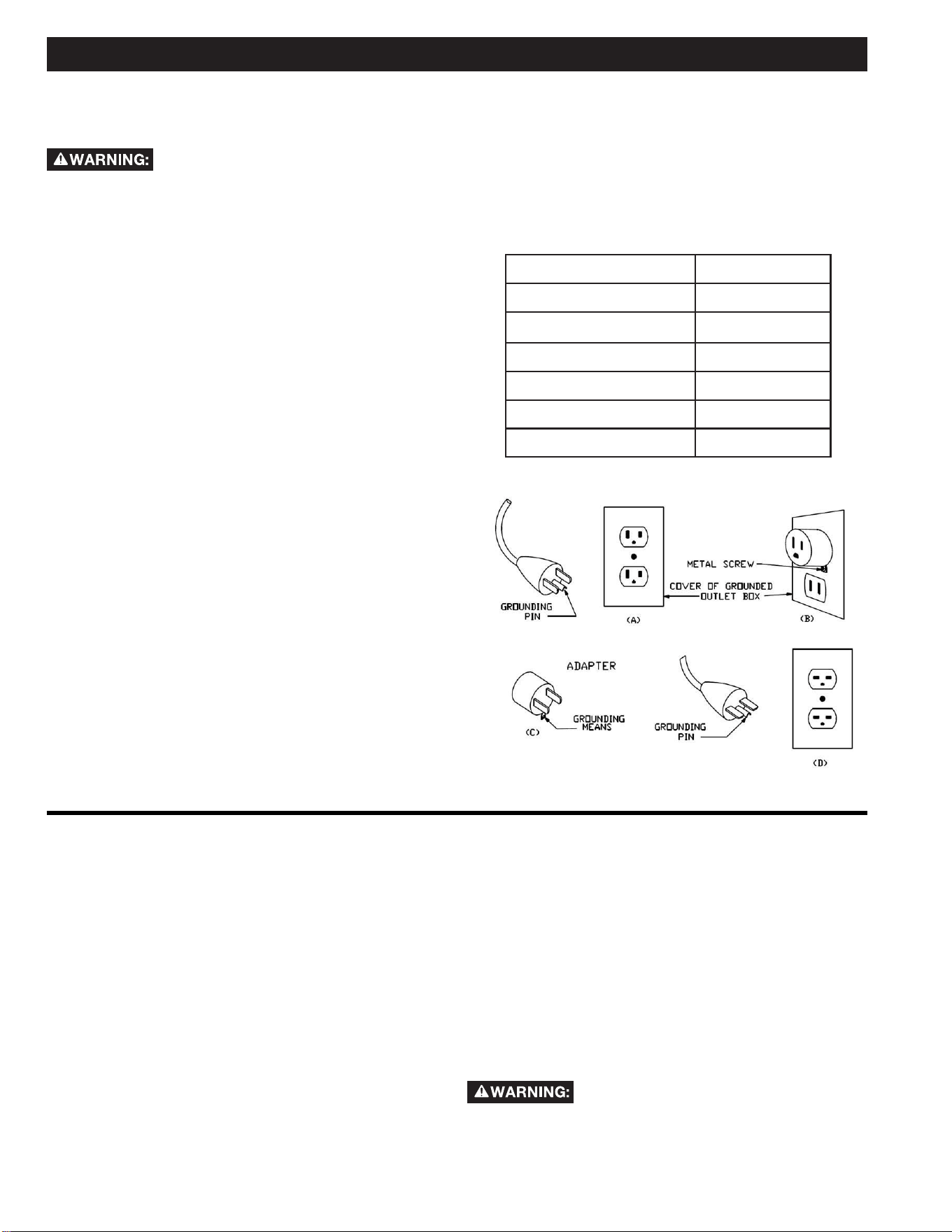
Grounded, cord-connected tools intended for use on a supply
circuit having a nominal rating less than 150 volts:
This tool is intended for use on a circuit that has an outlet
that looks like the one illustrated in Sketch (A). The tool has a
grounding plug that looks like the plug illustrated in Sketch (A).
A temporary adapter, which looks like the adapter illustrated in
Sketches (B) and (C), may be used to connect this plug to a
2-pole receptacle as shown in Sketch (B) if a properly grounded
outlet is not available. The temporary adapter should be used
only until a properly grounded outlet can be installed by a
qualified electrician. (This adapter is not permitted in Canada)
The green-colored rigid ear, lug, and the like, extending from
the adapter must be connected to a permanent ground such as
a properly grounded outlet box.

11
KEEP the extension cord clear of the work area. Position the cord so it will not get caught on lumber, tools or other
obstructions
• Use proper extension cords. Make sure your extension cord is a 3-wire extension cord which has a 3-prong grounding type
plug and matching receptacle which will accept the machine’s plug. When using an extension cord, be sure to use one heavy
enough to carry the current of the machine. An undersized cord will cause a drop in line voltage, resulting in loss of power and
overheating. The table below shows the maximum gauge to use depending on the cord length. If in doubt, use the next heavier
gauge. The smaller the gauge number, the heavier the cord. ONLY round, jacketed cords listed by Underwriter’s Laboratories
(UL) should be used.
NEVER use a damaged extension cord. Check extension cords before each use. If damaged, replace immediately.
Touching the damaged area could cause electrical shock resulting in serious injury.
IN ALL CASES, MAKE CERTAIN THE RECEPTACLE IN QUESTION IS PROPERLY GROUNDED. IF YOU ARE
NOT SURE, HAVE A QUALIFIED ELECTRICIAN CHECK THE RECEPTACLE.
EXTENSION CORDS
Table A
Minimum gauge for cord
Ampere Rating Volts Total length of cord in feet
120 25 50 100 150
150 50 100 200 300
More Than Not More Than AWG
0 6 18 16 16 14
6 10 18 16 14 14
10 12 16 16 14 Not recommended
12 16 14 12
ONLY the applicable parts of the Table need to be included. For instance, a 120V product need not include the 240V heading.
MOTOR SPECIFICATIONS AND ELECTRICAL REQUIREMENTS
MOTOR SAFETY PROTECTION
IMPORTANT: To reduce the risk of motor damage, the motor
should be blown out or vacuumed frequently to keep sawdust
from interfering with normal motor ventilation.
1. Connect this tool to a power source with the appropriate
voltage for your model and a 15-amp branch circuit with
a 15-amp fuse or circuit breaker. Using the wrong size
fuse can damage the motor.
2. If the motor won’t start, turn off the power switch
immediately and unplug the tool. Check the spindle to
make sure it turns freely. If the spindle is free, try to start
the motor again. If the motor still does not start, refer to
the “Troubleshooting” chart.
3. If the motor suddenly stalls while sanding, turn o the
power switch, unplug the tool, and remove the workpiece
from the belt/drum. The motor may now be restarted
and the sanding nished.
4. Fuses may “blow” or circuit breakers may trip frequently
if:
a. Motor Is Overloaded-Overloading can occur if you
sand too rapidly or make too many start/stops in a
short time.
b. Line voltages should not be more than 10% above
or below the nameplate voltage. For heavy loads,
however, the voltage at motor terminals must equal
the voltage specied for your model.
5. Most motor troubles may be traced to loose or incorrect
connections, overload, low voltage (such as small size
wire in the supply circuit) or to overly long supply circuit
wire. Always check the connections, the load and supply
circuit whenever motor doesn’t work well. Check wire
sizes and extension cord length with the Wire Size Chart.
Extension Cord
Length
Gauge (A.W.G.)
0-25 Ft.
26-50 Ft.
16
14
Wire Sizes
NOTE: Make sure the proper extension cord is used and is in
good condition. The use of any extension cord will cause loss of
power. To keep this to a minimum and to prevent overheating and
motor burn-out, use the table shown to determine the minimum
wire size (A.W.G.) extension cord.
Use only 3-wire extension cords with 3-prong grounding type
plugs and 3-pole receptacles.
12
For your own safety, never connect plug to
power source outlet, or insert switch key until all assembly steps
are complete and until you have read and understood the entire
owners manual.
To reduce the risk of injury, if any parts are
missing, do not attempt to assemble the sander, plug in the power
cord, or turn the switch on until the missing parts are obtained
and installed correctly.
1. Remove tool from carton by lifting unit.
2. Place the tool on a secure, stationary work surface and
look the tool over carefully.
UNPACKING AND CHECKING CONTENTS
NOTE: Before beginning assembly, check that all parts are
included. If you are missing any part, do not assemble the sander.
Call 1-888-359-4778 or E-mail us at: RidgidWoodworking@
ridgidproducts.com if any parts are damaged or missing.
Sometimes small parts can get lost in packaging material. Do not
throw away any packaging until sander is put together. Check
packaging for missing parts before contacting RIDGID
®.
NOTE: The sander is shipped with the 4 inch x 24 inch sanding
belt.
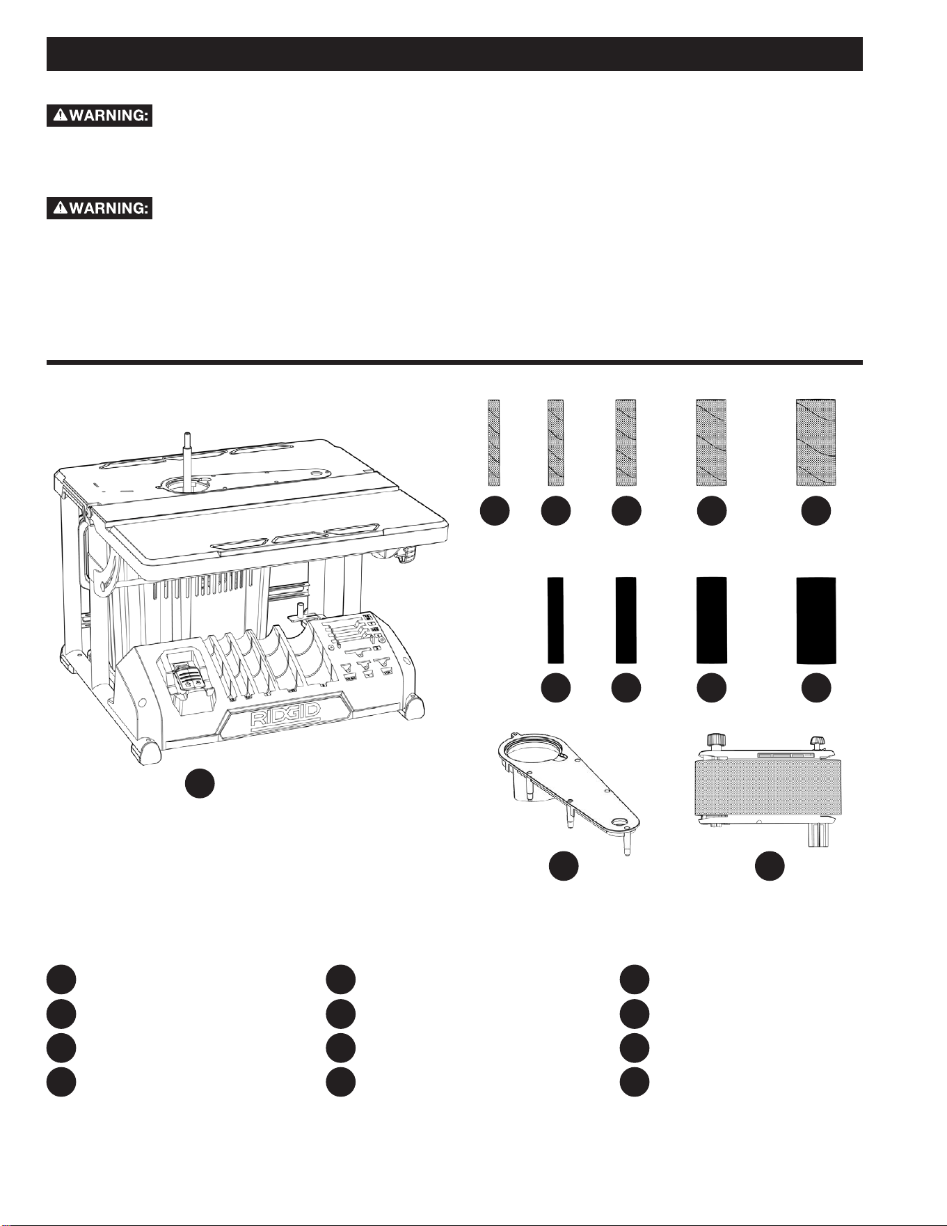
NOTE: Parts shown are not actual size.
PACKAGE CONTENTS DESCRIPTION
Oscillating Edge Belt/Spindle Sander
1/2 inch x 4 1/2 inch Sanding Sleeve
3/4 inch x 4 1/2 inch Sanding Sleeve
1 inch x 4 1/2 inch Sanding Sleeve
PC1 PC9
PC2 PC10
PC3 PC11
PC4
PC6
PC12
PC5
PC7
PC8
PC10
PC11 PC12
PC1
1 1/2 inch x 4 1/2 inch Sanding Sleeve
2 inch x 4 1/2 inch Sanding Sleeve
3/4 inch x 4 1/2 inch Drum
1 inch x 4 1/2 inch Drum
1 1/2 inch x 4 1/2 inch Drum
2 inch x 4 1/2 inch Drum
Table Insert
Sanding Belt Assembly
PC2 PC6
PC7 PC8 PC9
PC3 PC4 PC5
13
HP1
HP2
HP3
HP4
HP5
HP7
HP9
HP8
HP6 HP10
HP11
HP12
HP13
ASSEMBLY
To reduce the risk of injury from tool movement,
the supporting surface where sander is mounted should be
examined carefully after mounting to insure no movement during
use can result. If any tipping or walking is noticed, secure to
workbench or supporting surface before operating sander.
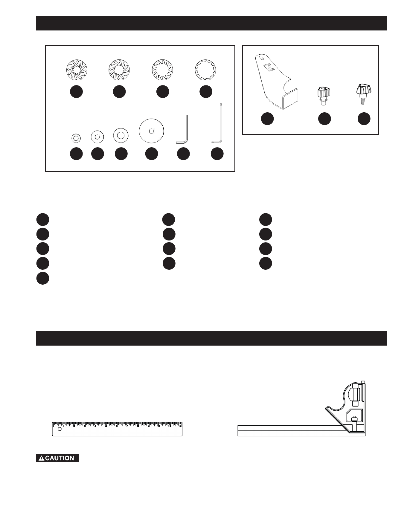
TOOLS NEEDED FOR ASSEMBLY OR ADJUSTMENTS.
Straight Edge
Combination Square
CONTENTS OF HARDWARE BAGS
006634
006676
006635
006680
006684
006683
006682
006681
006697
006602
006679
006678
006677
UNPACKING AND CHECKING CONTENTS
HP1 HP3 HP4
HP8
HP7
HP6
HP5
HP9 HP10
1/2 - 3/4 inch Spacer Ring Insert
1 inch Spacer Ring Insert
1 1/2 inch Spacer Ring Insert
2 inch Spacer Ring Insert
1/2 - 3/4 inch Washer
1 inch Washer
1 1/2 inch Washer
2 inch Washer
2.5mm Hex Wrench
T25 Torx Wrench
Work Rest
Spindle Knob
Work Rest Knob
HP2
HP11 HP12 HP13
14
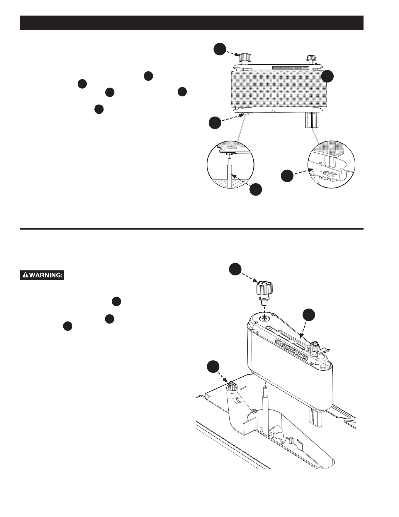
INSTALLING THE SANDING BELT
ASSEMBLY
1. Slide Belt Assembly down Motor Shaft
A
. Align Drive
Drum Spline
B
with the slots in the fan. Place
Sanding Belt Assembly
PC12 into the Wear Plate
C
opening as shown.
2. Tighten Spindle Knob
HP12
. DO NOT overtighten.
NOTE: Knob turns counterclockwise to tighten.
3. Install Sanding Belt, see Removing/Installing the
Sanding Belt section.
See Figure 1.
Removing the Sanding Belt
Assembly
To reduce the risk of injury from accidental
start, make sure tool is unplugged before removing the sanding
belt assembly.
1. Loosen the work rest knob
HP13
and pivot the work rest
out of the way. Tighten the work rest knob.
2. Remove the spindle knob
HP12
and lift o the sanding belt
assembly
PC12
. NOTE: Knob turns clockwise to loosen.
3. Store assembly on bracket in rear of base.
See Figure 2.
ASSEMBLY
FIGURE 1
FIGURE 2
PC12
HP12
HP12
C
B
A
PC12
HP13
15
ASSEMBLY
FIGURE 3
FIGURE 4
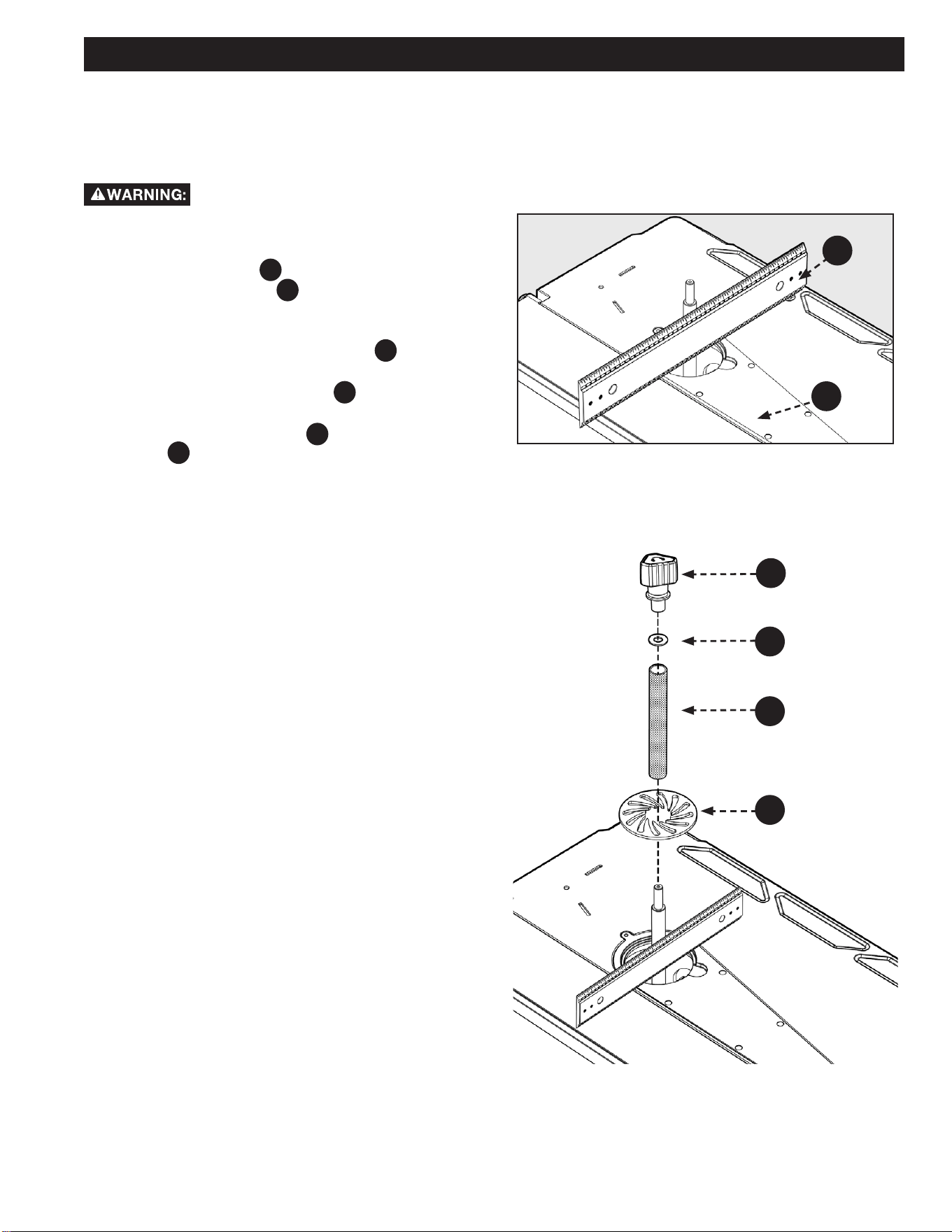
INSTALLING 1/2 INCH DIAMETER
SANDING SLEEVE
To install the table insert, see Figures 3 and 4.
To reduce the risk of injury from accidental
starting, always turn switch “OFF”, unplug the sander and remove
switch key before removing or replacing the spacer ring inserts,
sleeves and drums.
1. Use a straight edge
A
as shown in Figure 3 to make
sure the table insert
PC11
is flush with the table. If
necessary adjust the set screws in the table insert with
the 2.5mm Hex Wrench provided.
2. Position 1/2 inch spacer ring insert
HP1
in the table
recess.
3. Locate 1/2 inch sanding sleeve
PC2
and slide it on the
spindle. (Rubber drum is not used.)
4. Install the 1/2 inch washer
HP5
and tighten the spindle
knob
HP12
. Do not overtighten. NOTE: Knob turns
counterclockwise to tighten.
A
HP5
PC2
HP1
HP12
PC11
16
SELECTION OF SPACER RING
INSERTS AND UPPER SPINDLE
WASHERS
Using the wrong spacer ring insert may permit
small pieces of wood or nger tips to become wedged between
the abrasive surface and the insert.
Sanding Sleeve Spacer Ring Insert
Upper Spindle Washer
1/2 inch
1/2 inch 1/2 inch
3/4 inch
1 inch 1 inch
1 inch
1 1/2 inch 1 1/2 inch
1 1/2 inch
2 inch 2 inch 2 inch
• Use the smallest spacer ring insert that will t over the drum.
ASSEMBLY
FIGURE 5
• Use the largest upper spindle washer that will not protrude
past sanding sleeve.
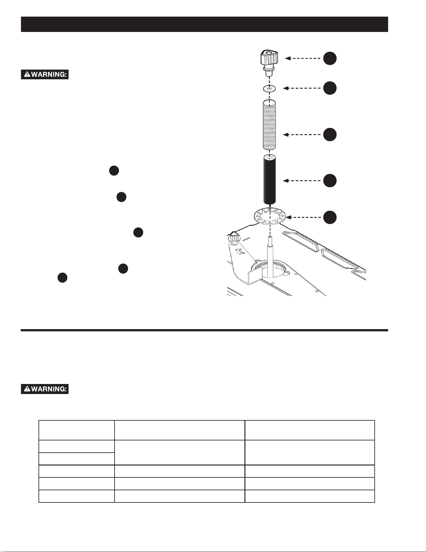
INSTALLING SANDING SLEEVES
LARGER THAN 1/2 INCH
To reduce the risk of injury from accidental
starting, always turn switch “OFF” and remove switch key before
removing the spacer ring inserts, sleeves and drums. See Figures
3 and 5.
1. Install the table insert.
2. Use a straight edge as shown to make sure the table
insert is ush with the table. If necessary adjust the set
screws in the table insert with the 2.5mm hex wrench
provided. There are ve set screws on the bottom side of
the Table Insert and one set screw in the table beneath
the Table Insert.
3. Slide the sanding drum
A
onto the spindle. NOTE: If
the drum is difficult to slide over the spindle, apply
talcum powder to the spindle.
4. Position spacer ring insert
B
in the table recess. (See
recommended spacer ring insert selection area from table
on page 15). Use the smallest spacer ring insert that will
t over the drum.
5. Place desired sanding sleeve
C
on correct drum.
NOTE: If the sanding sleeve is dicult to slide over the
drum, apply talcum powder to the outside surface of the
rubber drum.
6. Install the correct washer
D
and tighten the spindle
knob
HP12
. DO NOT overtighten. NOTE: Knob turns
counterclockwise to tighten.
HP12
D
C
A
B
17
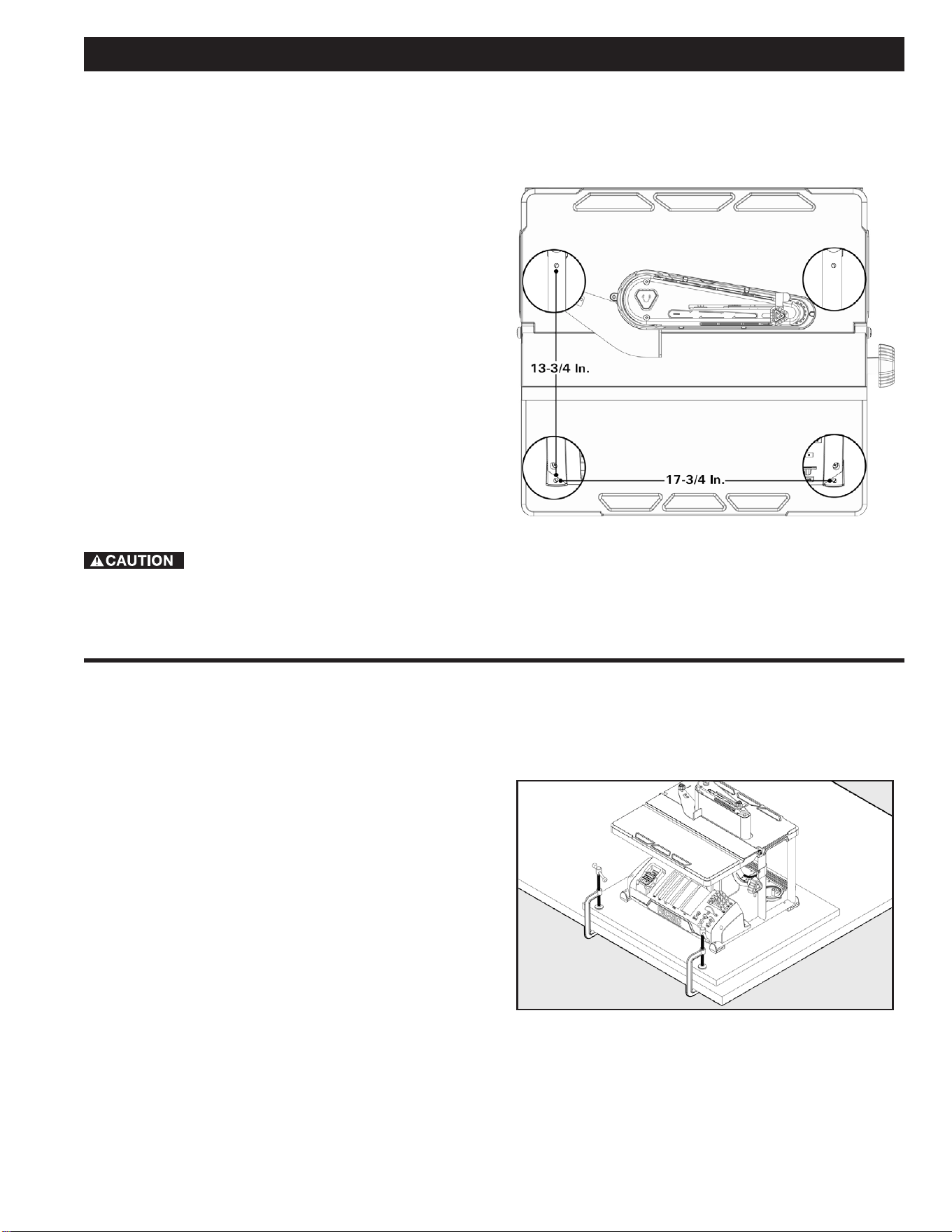
BOLTING OSCILLATING EDGE
BELT/SPINDLE SANDER TO
WORKBENCH
If sander is to be used in a permanent location, it should
be fastened securely to a rm supporting surface such as a
workbench, with either bolts or deck screws. See Figure 6.
Fastening with bolts
1. Use 1/4 inch bolts, washers, and nuts (not included).
The bolt length should be 2 inch plus the thickness of
the workbench.
2. Locate and mark the holes where the sander is to be
mounted.
3. Drill (4) 3/8 inch diameter holes through workbench.
4. Place sander on workbench, aligning holes in base with
holes drilled in workbench.
5. Insert (4) 1/4 inch diameter bolts and washers and
attach nuts securely.
Fastening with screws
Drive (4) 2 1/2 inch long screws through the holes in the base
and through the workbench. Do not overtighten the screws.
To reduce the risk of injury from tool movement,
use either 1/4 inch diameter screws and nuts or 2 1/2 inch long
deck screws.
CLAMPING OSCILLATING EDGE
BELT/SPINDLE SANDER TO
WORKBENCH
An alternative method of mounting is to fasten the sander to a
mounting board. The board should be sucient size to avoid tipping
while in use. Any good grade of plywood or chipboard with a 3/4
inch thickness is recommended. (Thinner chipboard can break.)
NOTE: For proper stability, holes must be countersunk so screw
heads are ush with the bottom surface of supporting board.
See Figure 7.
ASSEMBLY
FIGURE 6
FIGURE 7
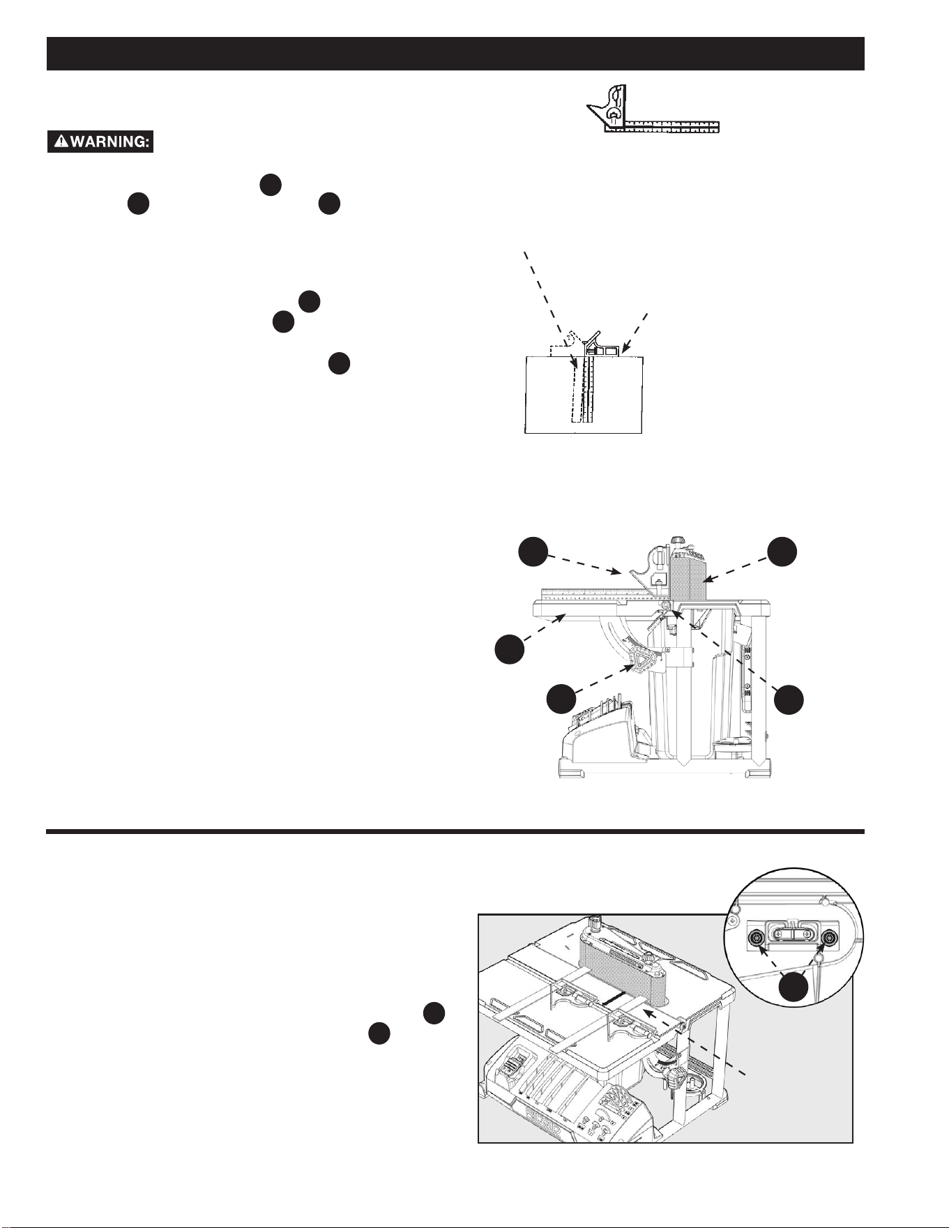
18
Straight Edge of Board
3/4 inch Thick, This Edge MUST
Be Perfectly Straight
Should be NO Gap or Overlap when Square
is Flipped Over in Dotted Position
SQUARING FRONT TABLE
To reduce the risk of injury from accidental
start, make sure tool is unplugged before aligning. See Figure 3
and 5. Use a combination square
A
to check the angle of the
front table
F12
with the sanding belt
PC12
. (NOTE: It is
recommended to verify the combination square is “true” before
use. See procedure on this page (Combination square not
supplied.)
See Figure 8.
1. If the front table is not 90° to the sanding belt:
a. Use the 2.5mm hex wrench
HP9
provided and “back
out” both set screws
B
located on each side
underneath the table.
b. Loosen the front table lock knob
F5
and adjust the
front table 90° to the sanding belt.
c. Tighten the front table lock knob .
d. Adjust both set screws to contact the front table.
e. Loosen table lock knob and move front table away
from and then back to the stop. Tighten table lock
knob and recheck.
MAKING ADJUSTMENTS
Adjust the belt
assembly to be
parallel or same
distance from the
miter gauge slot.
ALIGNING BELT TO MITER GAUGE
SLOT
In order to check and make sure the belt is parallel to the miter
gauge groove, please see below:
See Figure 9.
1. Use a combination square to check the distance from the
miter gauge groove to the belt assembly as shown.
2. If adjustment is required, use the T25 Torx wrench
HP10
provided to loosen the two Torx screws
C
located
underneath the table.
3. Adjust the belt assembly as needed to make it parallel or
same distance from to the miter gauge slot.
4. Tighten two screws when parallel.
FIGURE 8
FIGURE 9
Combination square
Combination Square must be True
Draw Light Line on
Board Along This Edge
A PC12
F12
B
F5
C
19
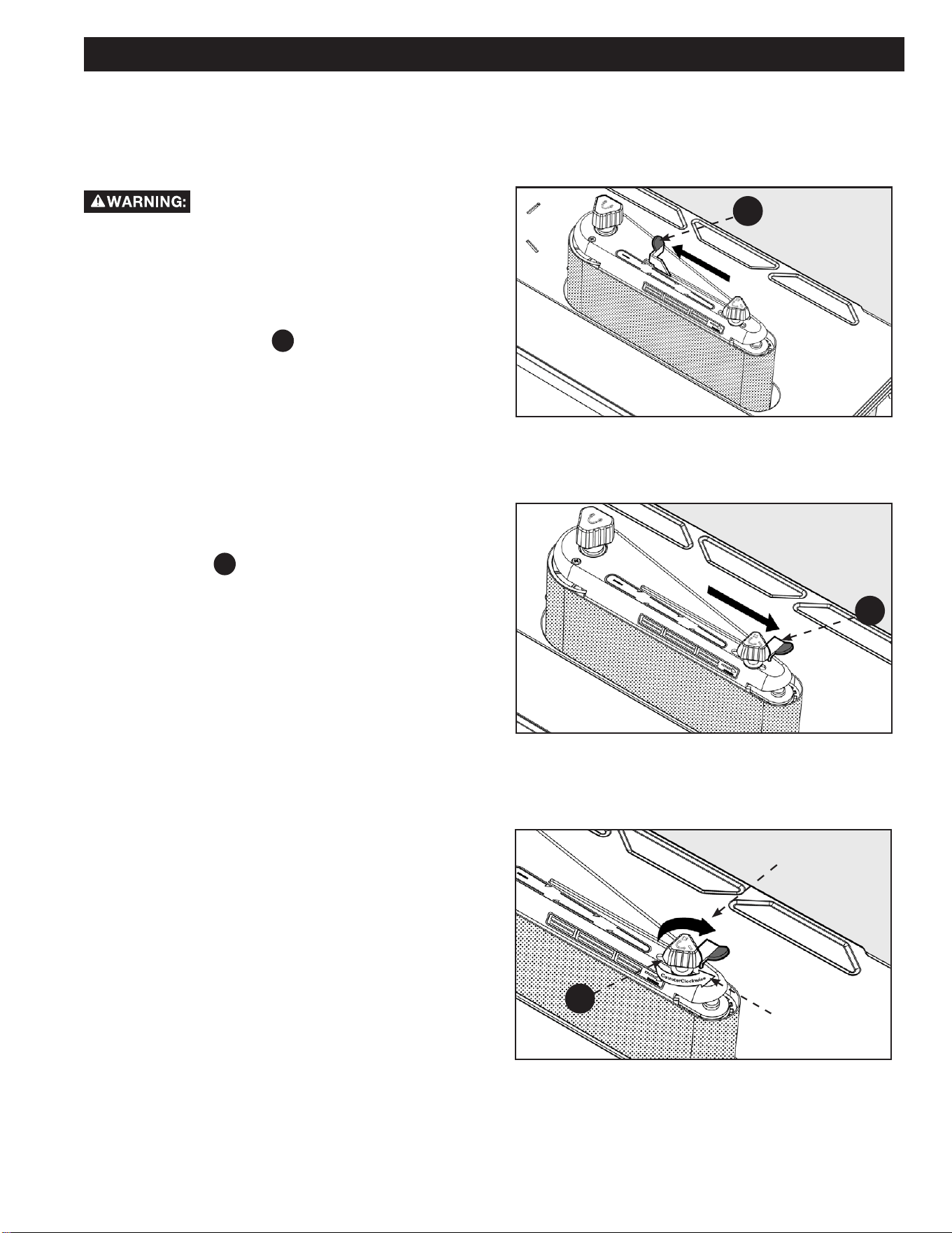
REMOVING/INSTALLING THE
SANDING BELT
Tensioning and Tracking
To reduce the risk of injury from accidental
start, make sure tool is unplugged before removing or installing
sanding belt.
Some sanding belts have a “directional arrow” on the inside
or smooth side. If there is an arrow, the belt must run in the
direction of the arrow so the splice will not come apart. If there is
no arrow the belt may be put on either direction.
1. Slide the tension lever
F3
to the left to release the belt
tension. See Figure 10.
2. Remove the sanding belt. Place the replacement sanding
belt over the drums as shown in gures. Make sure the
belt is centered on the left (larger) drum.
3. Slide the tension lever to the right to apply belt tension.
See Figure 11.
4. Turn the unit “ON” and immediately “OFF”, noting if the
belt tends to slide o the drums. If it did not tend to slide
o, it is tracking properly.
5. If the sanding belt runs down towards the table, turn the
tracking knob
F2
clockwise 1/4 turn. See Figure 12.
6. If the sanding belt, runs up away from the table, turn the
tracking knob counter clockwise 1/4 turn.
7. Be sure to ip the tension lever to loosen the belt and
readjust the sanding belt to be centered on the left
(larger) drum and then ip the tension lever back to the
locking position.
8. Turn switch “ON” and immediately “OFF” again, noting
belt movement. Readjust tracking knob if necessary.
MAKING ADJUSTMENTS
FIGURE 10
FIGURE 11
FIGURE 12
F3
F3
CLOCKWISE
(MOVES BELT UP)
F2
COUNTERCLOCKWISE
(MOVES BELT DOWN)
20
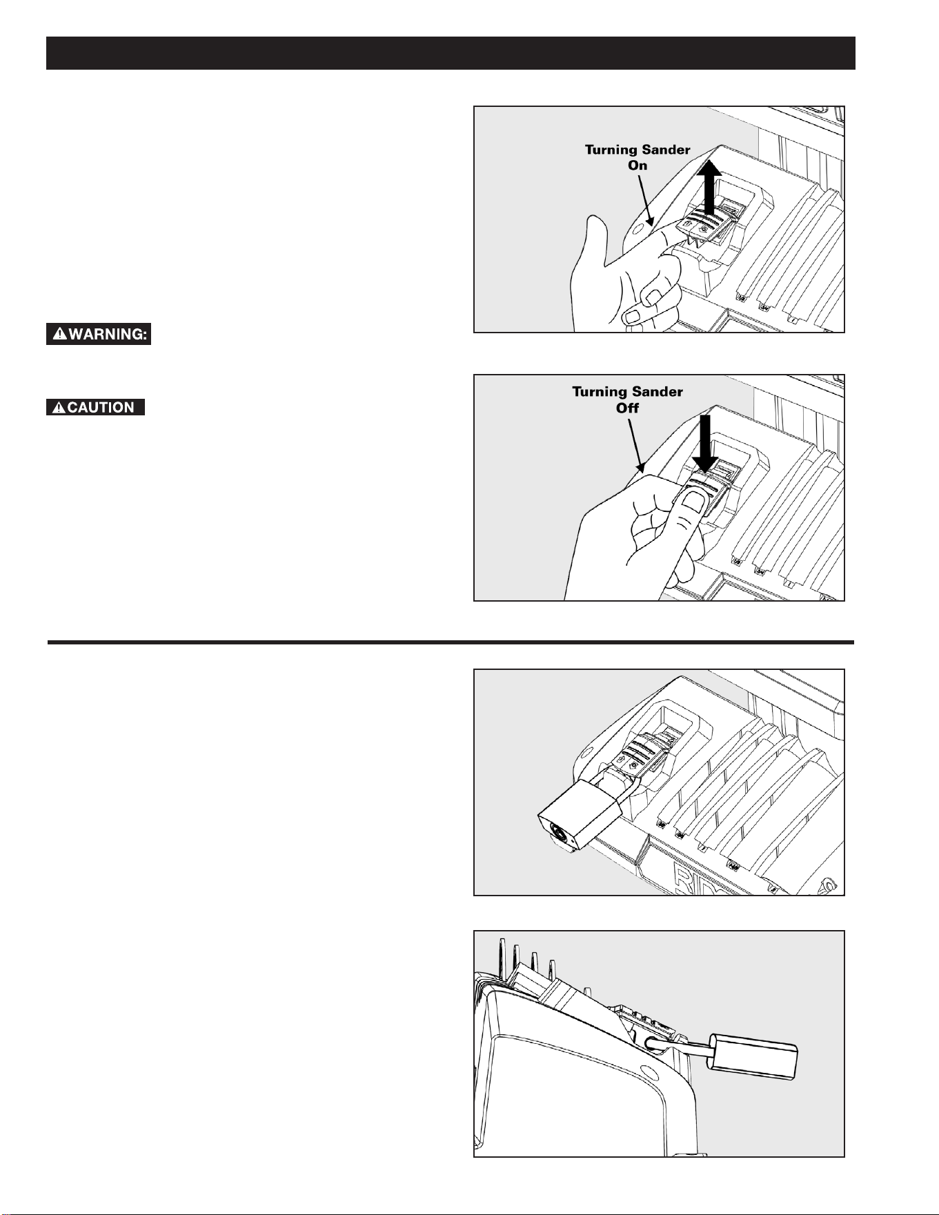
ON-OFF SWITCH
The On-O switch has a locking feature. This Feature is intended
to help prevent unauthorized and possible hazardous use by
children and others. See Figures 13 and 14.
1. To turn sander “ON” lift the red switch to enable power to
the machine.
2. To turn sander “OFF”. Push switch in.
3. To lock this switch while you are away, press the switch
to the o position and use a lock to lock the switch down
so the machine switch cannot be lifted to power it on.
For your own safety, always lock the switch
“OFF” when sander is not in use. Also, in the event of a power
failure (all of your lights go out) turn switch o.
Before turning switch on, make sure the belt or
drum and sleeve are properly installed.
ON-OFF SWITCH PADLOCK FEATURE
To avoid accidental starting by young children or others not
qualied to use the tool, the use of a padlock is required to lock
out ON/OFF Switch:
1. Open the Padlock.
2. Insert through hole in the start button.
3. Close the Padlock.
4. Place the Key in a safe place out of the reach of children.
See Figures 15 and 16.
OPERATION
FIGURE 13
FIGURE 14
FIGURE 15
FIGURE 16
21
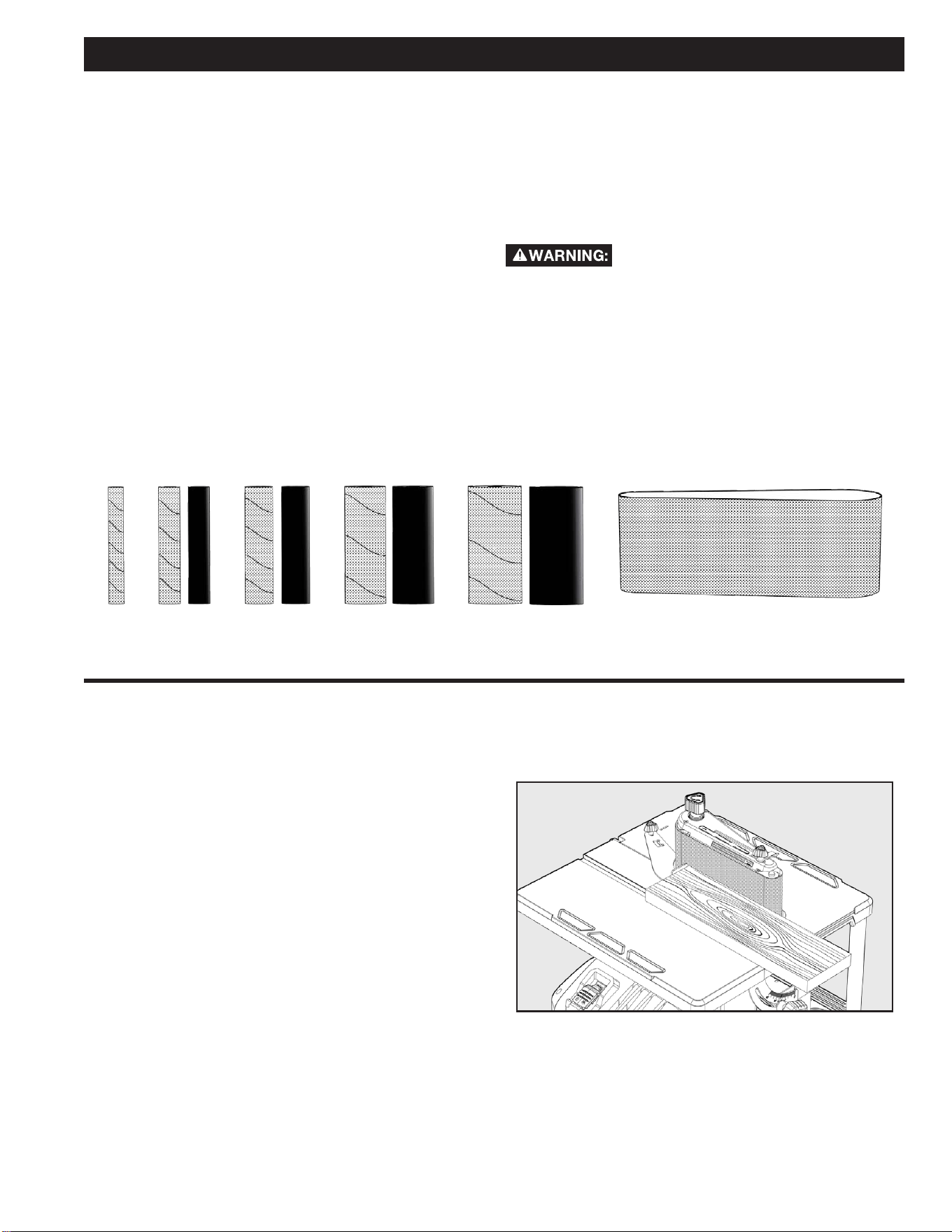
4 inch x 24 inch Sanding Belt
3/4 inch 1 inch 1-1/2 inch 2 inch1/2 inch
OPERATION
SANDPAPER SELECTION
Selecting the correct diameter, correct grit, and correct type of
sandpaper is an extremely important step in achieving a high
quality sanded nish. Aluminum oxide, silicon carbide, and other
synthetic abrasives are best for power sanding. Natural abrasives,
such as int and garnet, are too soft for economical use in power
sanding.
In general, coarse grit will remove the most material and ner
grit will produce the best nish in all sanding operations. The
condition of the surface to be sanded will determine which grit
will do the job. If the surface is rough, start with a coarse grit and
sand until the surface is uniform. Medium grit may then be used
to remove scratches left by the coarser grit and ner grit used for
nishing of the surface. Always continue sanding with each grit
until surface is uniform.
NOTE: DO NOT use sander without sandpaper. Doing so will
damage the rubber drum. Select and install the desired sanding
sleeve for your particular application. Sanding sleeves from 1/2
inch to 2 inch can be used with this sander. See Figure 17. Choose
one that is close in size to the workpiece you are sanding. Also
install the appropriate spacer ring insert (page 16).
Failure to use the correct size spacer ring insert
with its matching sanding sleeve could result in ngers being
pinched or the workpiece being pulled down between the spacer
ring insert and sanding sleeve.
NOTE: The correct size sanding belt is 4 inch x 24 inch. These
belts are available in coarse, medium and ne grits.
SURFACE SANDING ON THE
SANDING BELT
Maintain 1/16 in maximum clearance between table and sanding
belt or disc. When checking clearance between the sanding belt
and backstop, press the sanding belt at against the metal bed
beneath it. Hold the workpiece rmly with both hands, keeping
ngers away from the sanding belt. KEEP the end butted against
the backstop and move the work evenly across the sanding belt.
Use caution when sanding very thin pieces. For sanding long
pieces the backstop can be rotated out of the way. Apply only
enough pressure to allow the sanding belt to remove material.
See Figure 18.
FIGURE 17
FIGURE 18
22
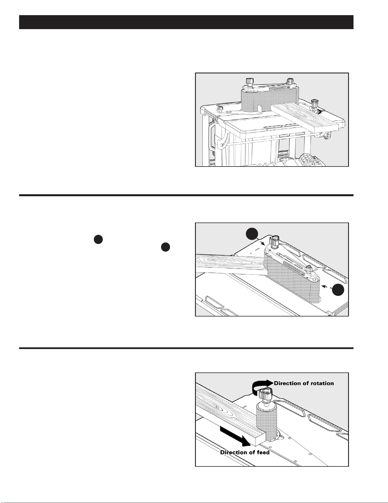
FEED DIRECTION
The sanding sleeve rotates clockwise. Feed the workpiece against
the sanding sleeve from left to right as shown. When fed from
left to right, the rotation of the sanding sleeve sands against the
workpiece. If fed in the opposite direction, the rotation forces
of the spinning sanding sleeve will tend to throw or bounce the
workpiece away from the sanding sleeve. This could cause loss of
control of workpiece or injury.
See Figure 21.
END SANDING ON THE SANDING
BELT
Move the work evenly across the sanding belt. For accuracy, use
a miter gauge accessory (not included).
See Figure 19.
SANDING CURVED EDGES
Inside curves are best sanded with the sander assembled in the
spindle mode. However, inside curves larger than 1 1/2 inch may
be sanded on the drive drum
A
when in the belt sander mode.
Although it is possible to lightly sand on the idler drum
B
end
of the belt sanding assembly, it is not recommended. The idler
drum is an integral part of the belt tracking mechanism. It is
spring loaded to maintain proper tension. Use of the idler drum to
sand curves may cause belt to track improperly.
See Figure 20.
OPERATION
FIGURE 19
FIGURE 20
FIGURE 21
B
A
23
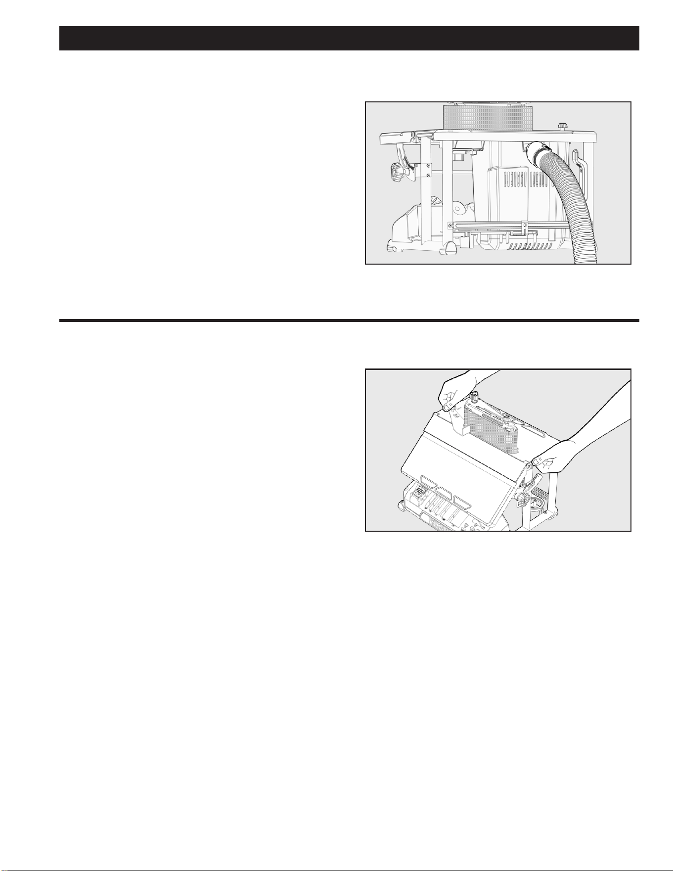
DUST COLLECTION CAPABILITY
A standard 2.5 inch dust exhaust port has been provided to make
dustless sanding possible. It is on the rear of your sander as
shown. The pickup adapter end of a vacuum hose ts inside the
dust exhaust port with a wedge t. Even with a dust collection
system, it is necessary to periodically clean sanding dust from
the recess in the table. Sawdust buildup in the table recess may
prevent the belt or spindle from making a complete oscillation,
which may cause premature wear.
See Figure 22.
TRANSPORTING SANDER
When using your sander in a portable application, it is acceptable
to lift and carry sander at the sides of the rear table by the
carry handles. Be careful when transporting to reduce the risk
of dislodging accessories, spacer ring inserts, wrench, and upper
spindle washers from their respective storage areas.
See Figure 23.
OPERATION
FIGURE 22
FIGURE 23

24
MAINTENANCE
ACCESSORIES
USE ONLY RECOMMENDED ACCESSORIES. Consult the owner’s manual for recommended accessories. The
use of improper accessories may cause risk of injury to persons.
A complete line of accessories is available from your RIDGID
® Supplier, RIDGID® Factory Service Centers, and RIDGID® Authorized
Service Centers. Please visit our Web Site www.RIDGID.com for an online catalog or for the name or your nearest supplier.
Since accessories other than those oered by RIDGID
® have not been tested with this product, use of such
accessories could be hazardous. For safest operation, ONLY RIDGID
® recommended accessories should be used with this product.
To reduce the risk of injury, turn unit o and disconnect it from power source before cleaning or servicing, before
installing and removing accessories, before adjusting and when making repairs. An accidental start-up can cause injury.
KEEP MACHINE CLEAN
Periodically blow out all air passages with dry compressed air. All plastic parts should be cleaned with a soft damp cloth.
NEVER use solvents to clean plastic parts. They could possibly dissolve or otherwise damage the material.
Wear certied safety equipment for eye, hearing and respiratory protection while using compressed air.
MAINTENANCE REMINDERS
For your own safety, turn the switch “OFF” and remove the plug from the outlet before adjusting or servicing your
sander.
To reduce the risk of electric shock or fire, all repairs to electrical systems should be performed only by qualified
service technicians. The unit must be reassembled exactly to factory specifications. Repair or replace any damaged or worn cords
immediately.
Blow or vacuum frequently to remove dust that may accumulate inside the motor.
Lubrication: All tool bearings are self-lubricating. They require no further lubrication.
For best performance use a shop vacuum or blower to keep saw blade area, the dust collection system, the guarding system and rails
free of saw dust and other debris.

25
TROUBLESHOOTING
For your own safety, turn switch “OFF”, and remove plug from power source outlet before troubleshooting your
sander. If any parts are missing, damaged or pre-assembled, do not assemble. Instead, call RIDGID
® Customer Service at
(toll free) 1-888-359-4778 .
FAILURE TO START
If your machine fails to start, check to make sure the prongs on the cord plug are making good contact in the receptacle, and check
reset button on GFCI (If applicable). Also, check for blown fuses or open circuit breakers in your power line.
TROUBLE PROBABLE CAUSE REMEDY
Excessive noise
NOTE: The sander will
make some noise when it is
operating normally.
1.
Motor gearbox not operating correctly. 1. Consult Authorized Service Center, any attempt
to repair this motor or gearbox may create a
hazard unless repair is done by a qualified service
technician.
Motor fails to develop full
power, starts slowly, or fails
to come up to full speed.
NOTE: Low voltage
1.
Circuit overloaded with lights,
appliances and other motor.
2.
General overloading of power company
facilities.
3. Motor relay not operating.
1. Do not use sander on heavily loaded circuits.
2. Request a voltage check by qualified electrician.
3. Have relay replaced. Consult Authorized Service
Center. Any attempt to repair this relay may create
a hazard unless repair is done by a qualified service
technician.
Motor overheats 1. Motor overloaded. 1.
Reduce pressure on workpiece.
Motor stalls (resulting
in blown fuses or circuit
breakers)
1. Motor relay not operating.
2.
Voltage too low. Circuit overloaded
or general overloading of power
company facilities.
3.
Incorrect fuses or circuit breakers in
power line.
1.
Have relay replaced. Consult Authorized Service
Center. Any attempt to repair this relay may create
a hazard unless repair is done by a qualified service
technician.
2.
Request voltage check by qualified electrician.
3. Install correct fuse or circuit breaker.

26
TROUBLESHOOTING
TROUBLE PROBABLE CAUSE REMEDY
Frequent opening of fuse or circuits
breaker
1. Motor overloaded.
2.
Incorrect fuses or circuit breaker in
power line.
3. Relay not operating.
1. Feed work slower.
2.
Install correct fuse or circuit breakers.
3. Have relay replaced. Consult Authorized
Service Center. Any attempt to repair
this relay may create a hazard unless
repair is done by a qualied service
technician.
Motor will not run 1.
Damaged On-O Switch/Cord.
2. Burned out motor, no power to motor
or low voltage.
1.
Replace damaged parts before using
sander.
2.
Consult Authorized Service Center.
Any attempt to repair this motor may
create a hazard unless repair is done
by a qualied service technician.
Sanding drum or belt slips or slows down
easily
1.
Applying too much pressure to
workpiece.
2. Spindle knob loose.
1.
Reduce pressure on workpiece.
2. Tighten spindle knob.
Wood burns while sanding 1.
Sanding drum is glazed with sap. 1. Replace sandpaper.
Sandpaper doesn’t remove material 1.
Sandpaper is compacted with sawdust. 1. Replace sandpaper.
Spindle doesn’t go through full 3/4 inch
travel
1. Sawdust is compacted under lower
drum washer.
2. Damaged gearbox.
1.
Vacuum sawdust from area of lower
drum washer.
2.
Consult Authorized Service Center.
Any attempt to repair this gearbox
may create a hazard unless repair is
done by a qualied service technician.

27
PARTS, SERVICE OR WARRANTY ASSISTANCE
Proof of purchase must be presented when requesting warranty
service.
Limited to RIDGID® stationary power tools purchased 2/1/21 and
after. This product is manufactured by DPEC. The trademark is
licensed from RIDGID
®, Inc. All warranty communications should
be directed to Customer Service attn: RIDGID
® Stationary Power
Tool Technical Service at (toll free) 1-888-359-4778.
90-DAY SATISFACTION GUARANTEE POLICY
During the rst 90 days after the date of purchase, if you are
dissatised with the performance of this RIDGID
® Stationary
Power Tool for any reason you may return the tool to the dealer
from which it was purchased for a full refund or exchange. To
receive a replacement tool you must present proof of purchase
and return all original equipment packaged with the original
product. The replacement tool will be covered by the limited
warranty for the balance of the 5 YEAR service warranty period.
WHAT IS COVERED UNDER THE 5 YEAR
LIMITED SERVICE WARRANTY
This warranty on RIDGID® Stationary Power Tools covers all
defects in workmanship or materials in this Ridgid
® tool for ve
years following the purchase date of the tool. Warranties for other
RIDGID
® products may vary.
HOW TO OBTAIN SERVICE
To obtain service for this RIDGID® tool you must call RIDGID®
Customer Service at (toll free) 1-888-359-4778 or email us at
RidgidW[email protected]. When requesting
warranty service, you must present the original dated sales
receipt. The authorized service center will repair any faulty
workmanship, and either repair or replace any part covered under
the warranty, at our option, at no charge to you.
WHAT IS NOT COVERED
This warranty applies only to the original purchaser at retail
and may not be transferred. This warranty only covers defects
arising under normal usage and does not cover any malfunction,
failure or defect resulting from misuse, abuse, neglect, alteration,
modication or repair by other than an authorized service center
for RIDGID
® branded hand held and stationary power tools.
Consumable accessories pro vided with the tool such as, but not
limited to, blades, bits and sand paper are not covered.
RIDGID
®, MAKE NO WARRANTIES, REPRESENTATIONS
OR PROM ISES AS TO THE QUALITY OR PERFORMANCE OF
ITS POWER TOOLS OTHER THAN THOSE SPECIFICALLY
STATED IN THIS WARRANTY.
ADDITIONAL LIMITATIONS
To the extent permitted by applicable law, all implied warranties,
including warranties of MERCHANTABILITY or FIT NESS FOR A
PARTICULAR PURPOSE, are disclaimed. Any implied warranties,
including warranties of merchantability or tness for a particular
purpose, that cannot be disclaimed under state law are limited
to ve years from the date of purchase. RIDGID
®, Inc. is not
responsible for direct, indirect, incidental or consequential
damages. Some states do not allow limitations on how long
an implied warranty lasts and/or do not allow the exclusion or
limitation of incidental or consequential damages, so the above
limitations may not apply to you. This warranty gives you specic
legal rights, and you may also have other rights which vary from
state to state.
DPEC
2651 New Cut Road
Spartanburg, SC 29303
RIDGID® STATIONARY POWER TOOL
5 YEAR LIMITED SERVICE WARRANTY

DPEC
2651 New Cut Road
Spartanburg, SC 29203
©2021
RIDGID® is a registered trademark and used under license.
Customer Service Information:
For parts or service, do not return this product to the store. Contact your nearest
RIDGID® authorized service center. Be sure to provide all relevant information when
you call or visit. For the location of the authorized service center nearest you, please
call 1-888-359-4778 or email us at RidgidW[email protected].
MODEL NO.*_____________________SERIAL NO.___________________________
*Model number on product may have additional letters at the end. These letters designate manufacturing
information and should be provided when calling for service.
DPEC006495
05/02/21 REV8
OPERATOR’S MANUAL
OSCILLATING EDGE BELT/SPINDLE SANDER
R4840