EGN 91 / EGN 92 / EGN 94 / EGN 96
EN
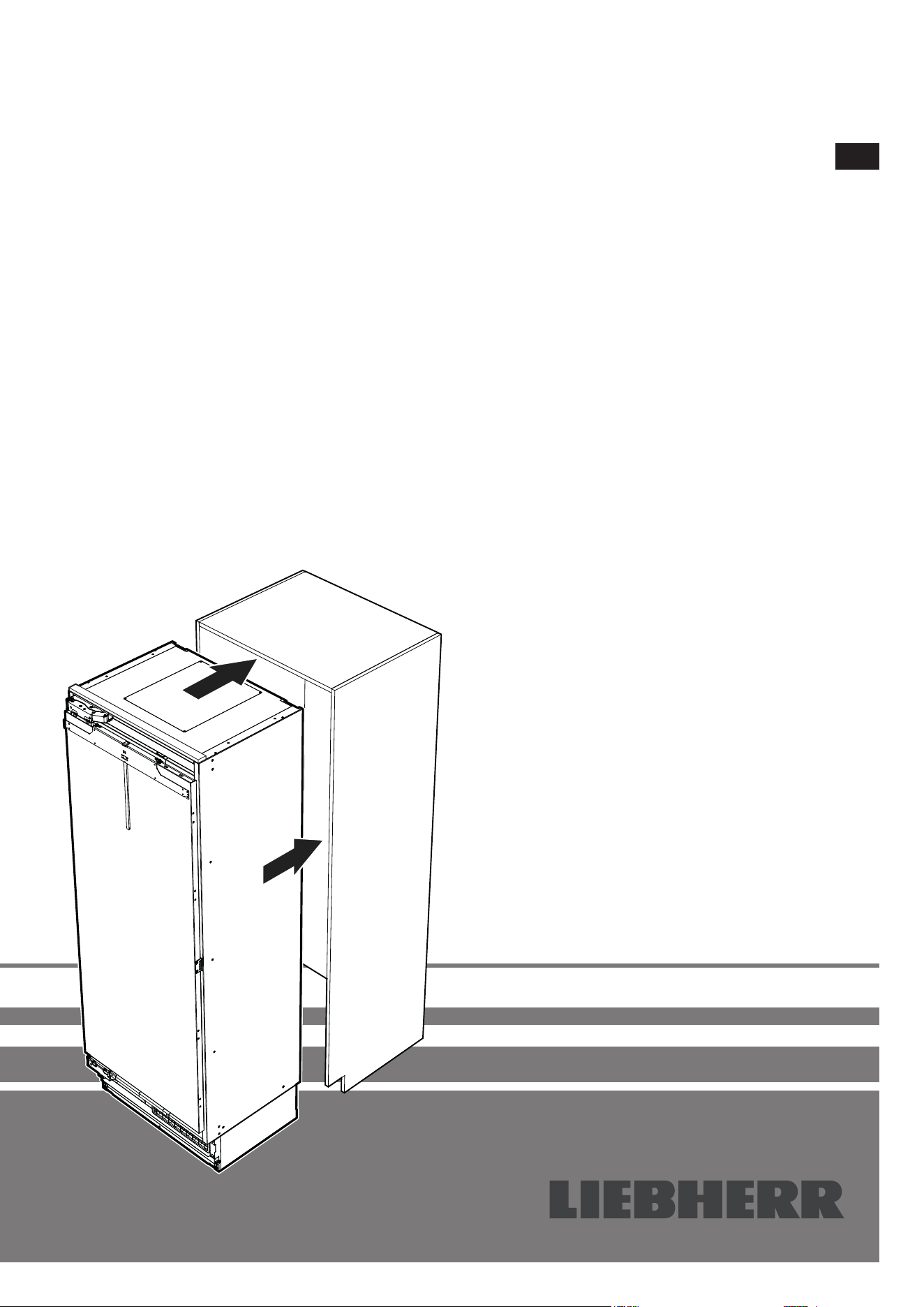
Installation instructions
Freezer Page 24
7085 745-00
24
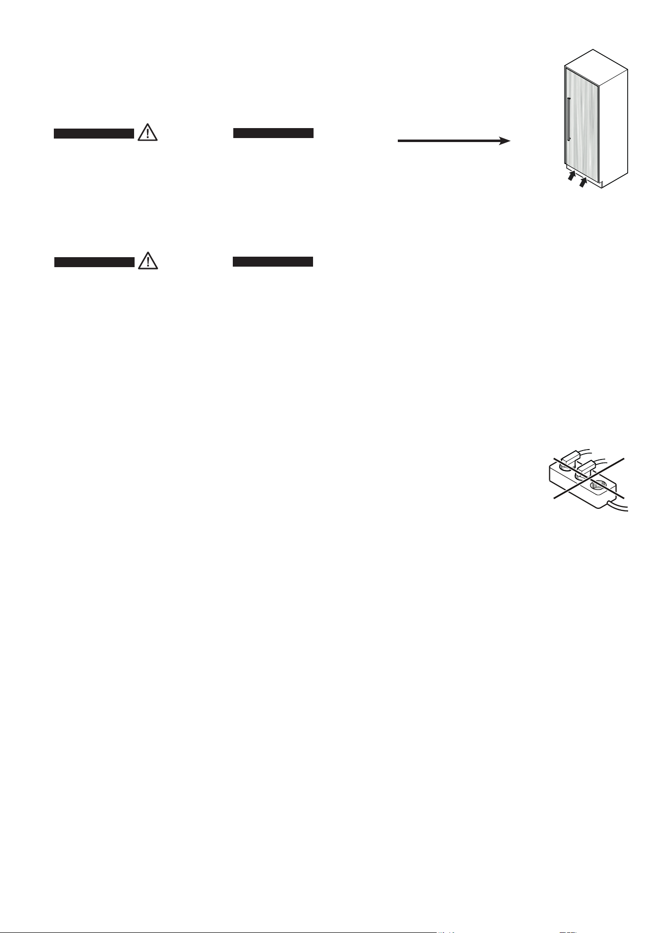
Please read and follow these instructions.
These instructions contain Danger, Warning and Caution notes.
This information is important for safe and efficient installation
and operation.
Always read and comply with all Danger, Warning and Caution
notes!
DANGER!
Danger indicates an imminent hazard
which will cause serious injury or death if
precautions are not followed.
WARNING!
Warning indicates a hazardous situation
which, if not avoided, could result in death
or serious injury.
CAUTION!
Caution indicates a potentially hazardous
situation which, if not avoided, may result
in minor or moderate injury.
IMPORTANT
This indicates information that is especially relevant to a
problem-free installation and operation.
Content
Please read and follow these instructions. ............................. 24
Note to the installer.................................................................25
Mounting the anti-tipping device ............................................25
Setting up ...............................................................................25
Electrical connection .............................................................. 25
Appliance dimensions ............................................................ 26
Door swing clearance (top view) ............................................27
Installation dimensions ...........................................................28
Panel dimensions ...................................................................30
Unpacking ..............................................................................32
Supplied accessories .............................................................34
Anti-tipping device ..................................................................35
Mounting the anti-tipping device ............................................35
Safety instructions and warnings for
water connection ..........36
Water connection requirements .............................................36
Appliance installation .............................................................36
Please note in case of removing appliance from the recess ..44
Important note for changing over door hinges or limiting
the door opening angle to 90° ................................................44
25
EN
Note to the installer
It is very important to follow the instructions in the manual to
ensure proper installation and operation of the appliance.
Before installing the appliance, be sure to thoroughly read and
understand all of the information in this manual.
WARNING!
Risk of electric shock.
Do not connect to the socket before the
installation is completed.
Mounting the anti-tipping device
WARNING!
To avoid a hazard due to instability of the
appliance, it must be secured in accordance
with the instructions.
Setting up
• Donotplacetheapplianceindirectsunlightor
near cookers, radiators and similar sources of
heat.
• Theflooronwhichtheappliancestandsshould
be horizontal and level.
•
Do not cover ventilation openings or
grilles.
• Standard EN378 specifies that the room in
which you install your appliance must have a
volume of 1 m
3
per 8 g of R 600a refrigerant used
in the appliance, so as to avoid the formation of
inflammable gas/air mixtures in the room where the appliance
is located in the event of a leak in the refrigerant circuit. The
quantity of refrigerant used in your appliance is indicated on
the type plate on the inside of the appliance.
Electrical connection
Only operate the appliance with alternating current (AC).
The permissible voltage and frequency are indicated on the
type plate. The position of the type plate is shown in the section
entitled Description of the appliance (Operating instructions).
The socket must be properly earthed and protected by a fuse.
The tripping current of the fuse must be between 10 A and 16 A.
Do not connect the appliance using an extension cable or exten-
sion socket.
Do not use stand-alone inverters (conversion
of direct current to alternating current/three-
phase current) or energy-saving plugs. Risk
of damage to the electronic control system!
26
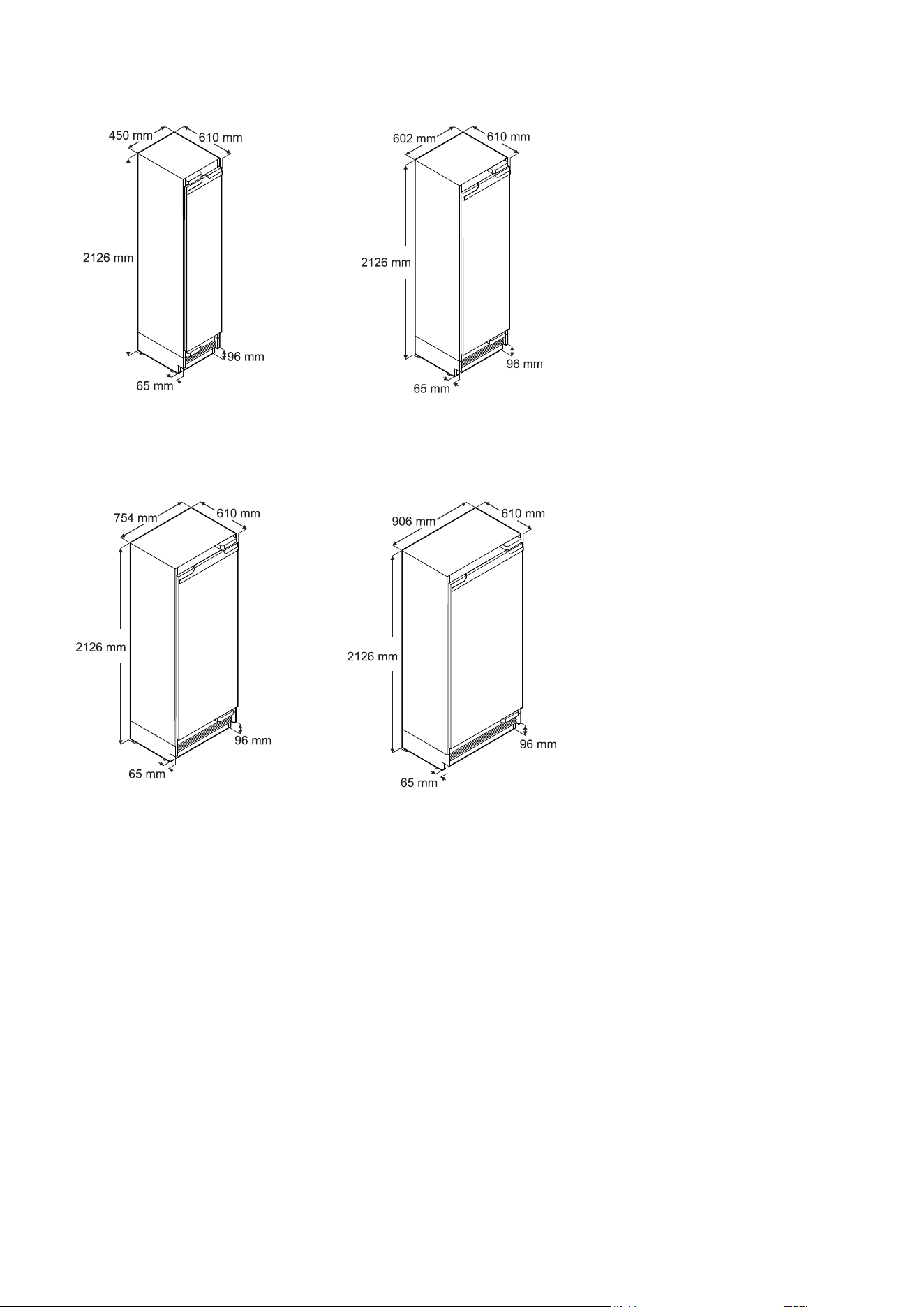
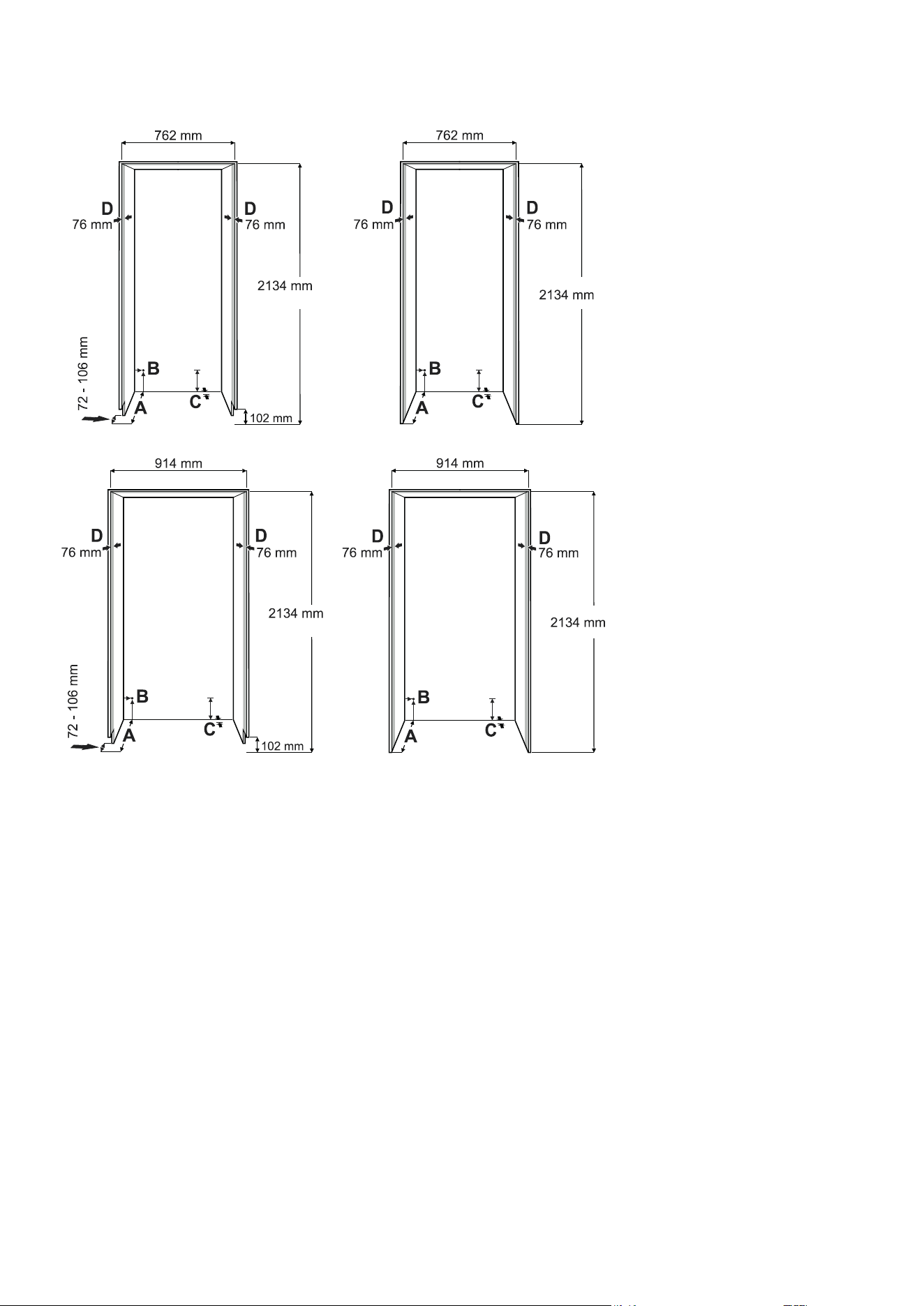
Appliance dimensions
EGN 9271
Stated minimum height dimensions include when the adjustable feet are fully inserted.
Width will increase by 6.5 mm when mounting strips are installed.
EGN 9171
EGN 9671EGN 9471
27
EN
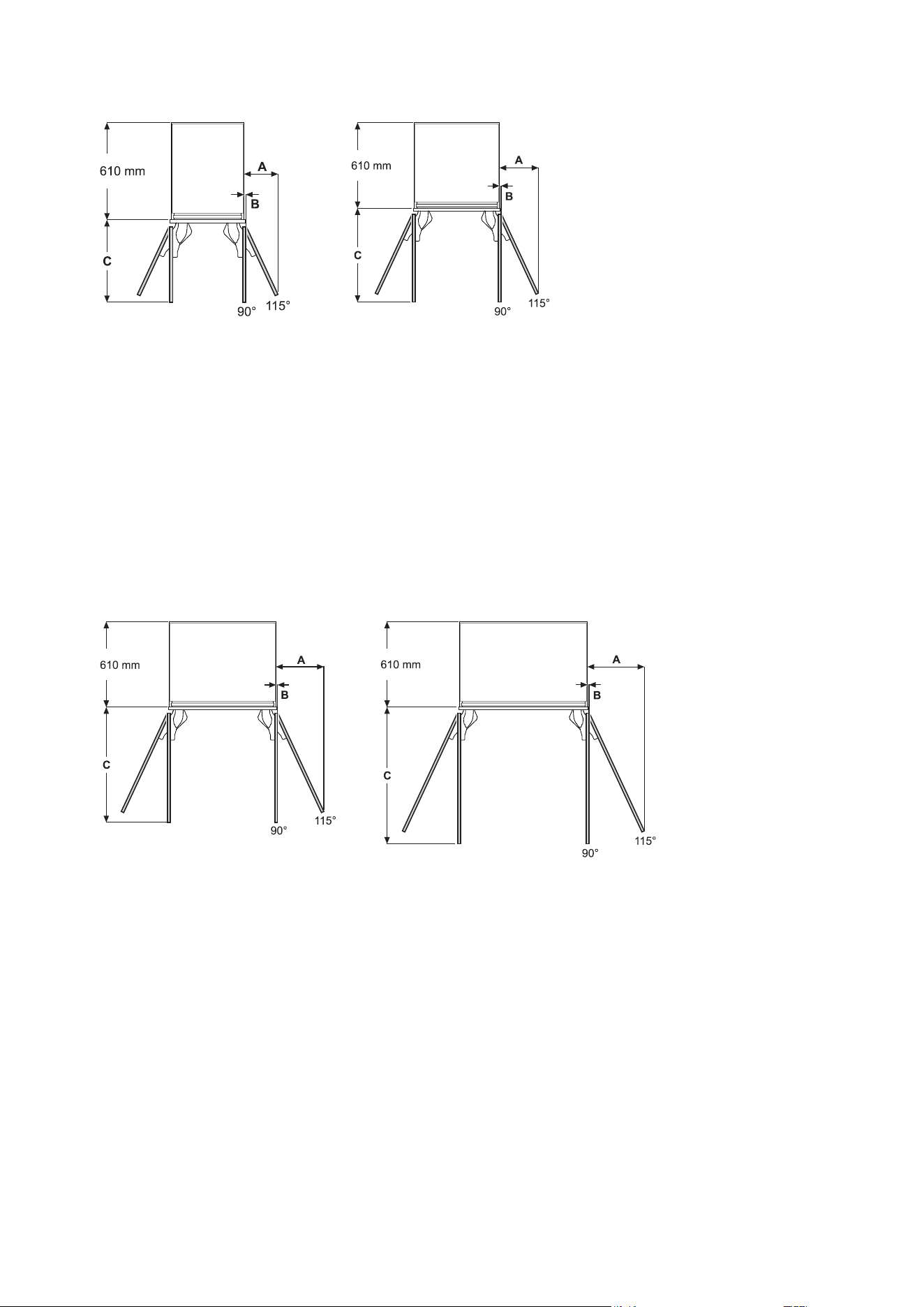
Door swing clearance (top view)
EGN 9271
Dimension A and B: add panel thickness and handle projection to calculate distance to wall.
Internal door panel
A = 273 mm
B = 12.5 mm
C = 658 mm
External door panel
A = 279 mm
B = 12.5 mm
C = 670 mm
Internal door panel
A = 210 mm
B = 12.5 mm
C = 505 mm
External door panel
A = 216 mm
B = 12.5 mm
C = 517 mm
EGN 9171
EGN 9471 EGN 9671
Internal door panel
A = 337 mm
B = 12.5 mm
C = 810 mm
External door panel
A = 343 mm
B = 12.5 mm
C = 822 mm
Internal door panel
A = 400 mm
B = 12.5 mm
C = 962 mm
External door panel
A = 406 mm
B = 12.5 mm
C = 975 mm
28
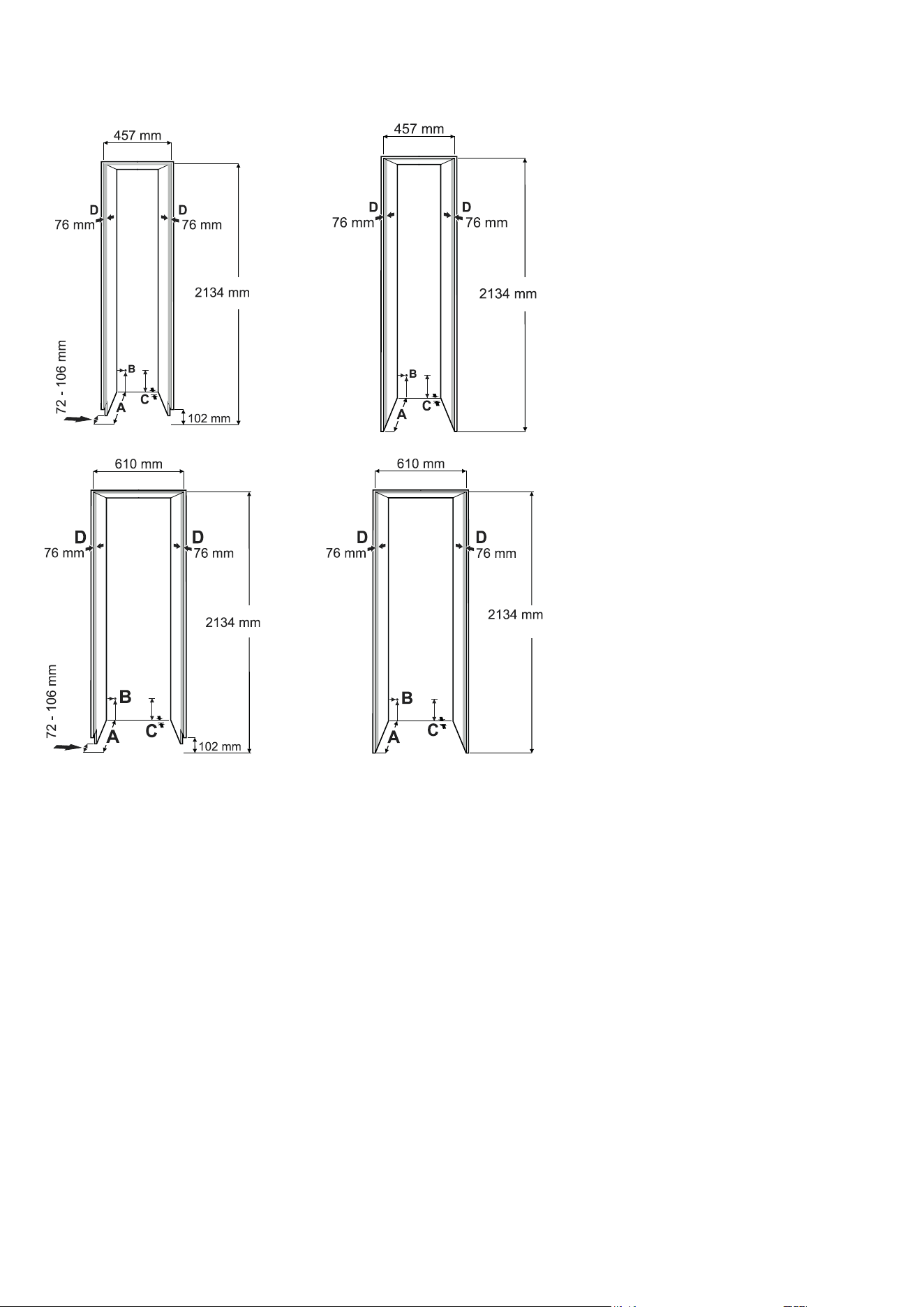
Installation dimensions
Continuous plinth panel Individual plinth panel
A
Recess depth for external door panel
= 635 mm
Recess depth for internal door pan-
el = 635 mm plus panel thickness
B
This is the point where the mains cable
exits from the appliance rear. 19 mm from
the left and 127 mm from the floor.
Free length of the mains cable is 2.5 m.
IMPORTANT
The socket must be easily
accessible so that the appliance
can be disconnected from the
mains quickly in an emergency.
It must not be behind the back of
the appliance.
C
The appliance has a recess in this area
for cable and water line laying.
25 mm in depth and 140 mm in height over
the whole width of the appliance.
D
This surface is visible when the appliance
door is open. Designed finish is required.
29
EN
Continuous plinth panel Individual plinth panel
A
Recess depth for external door panel =
635 mm
Recess depth for internal door pan-
el = 635 mm plus panel thickness
B
This is the point where the mains cable
exits from the appliance rear. 19 mm from
the left and 127 mm from the floor.
Free length of the mains cable is 2.5 m.
IMPORTANT
The socket must be easily
accessible so that the appliance
can be disconnected from the
mains quickly in an emergency.
It must not be behind the back
of the appliance.
C
The appliance has a recess in this area
for cable and water line laying.
25 mm in depth and 140 mm in height
over the whole width of the appliance.
D
This surface is visible when the appliance
door is open. Designed finish is required.
30
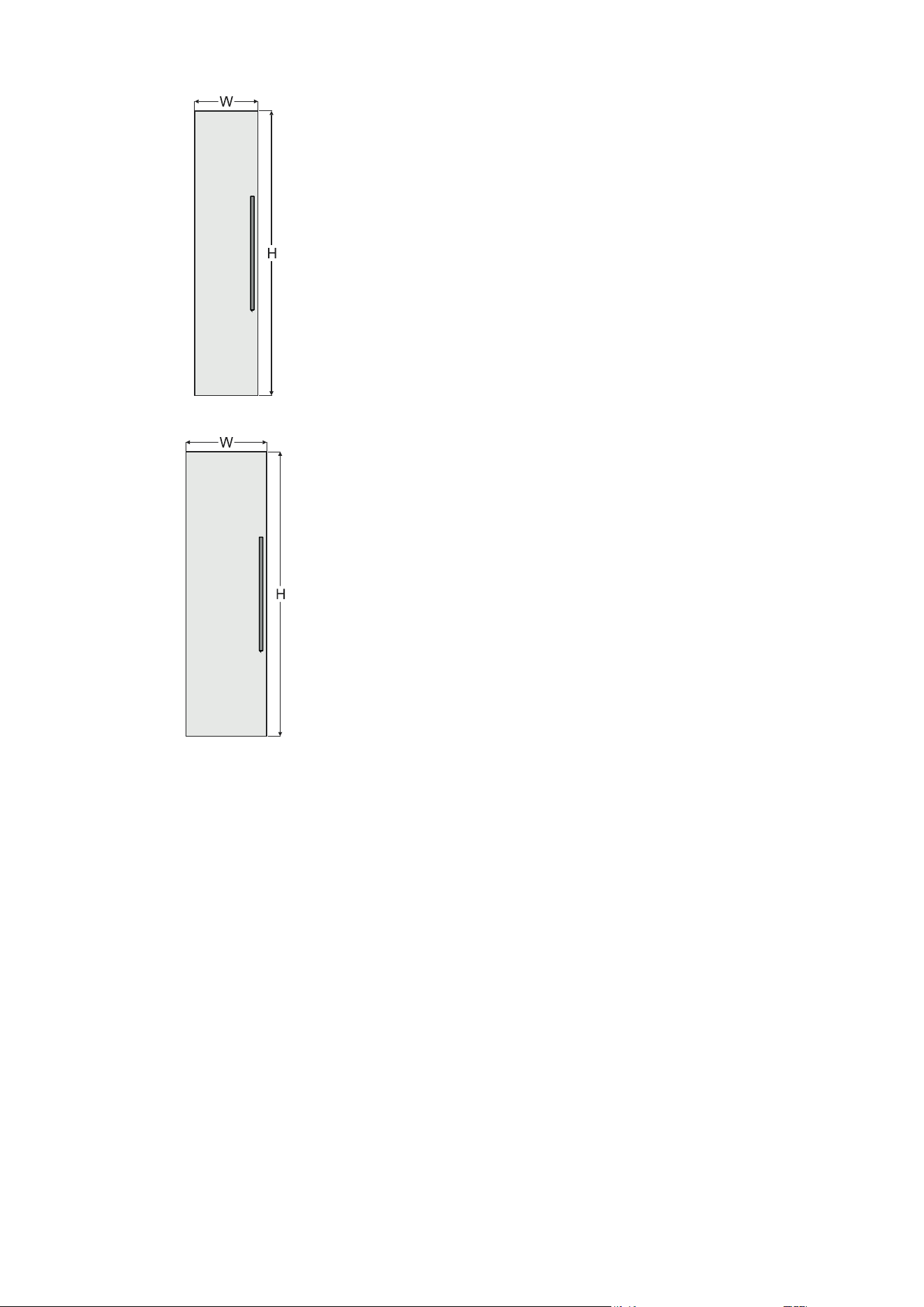
Panel dimensions
610 mm recess
Internal door panel
H = 2029 mm
W = 603 mm
External door panel
H = 2032 mm plus overlapping of the panel on the top
W = 610 mm plus overlapping of the panel on both sides
Minimum panel thickness = 16 mm
Maximum panel thickness = 25 mm
Maximum panel weight = 30 kg
457 mm recess
Internal door panel
H = 2029 mm
W = 451 mm
External door panel
H = 2032 mm plus overlapping of the panel on the top
W = 457 mm plus overlapping of the panel on both sides
Minimum panel thickness = 16 mm
Maximum panel thickness = 25 mm
Maximum panel weight = 25 kg
31
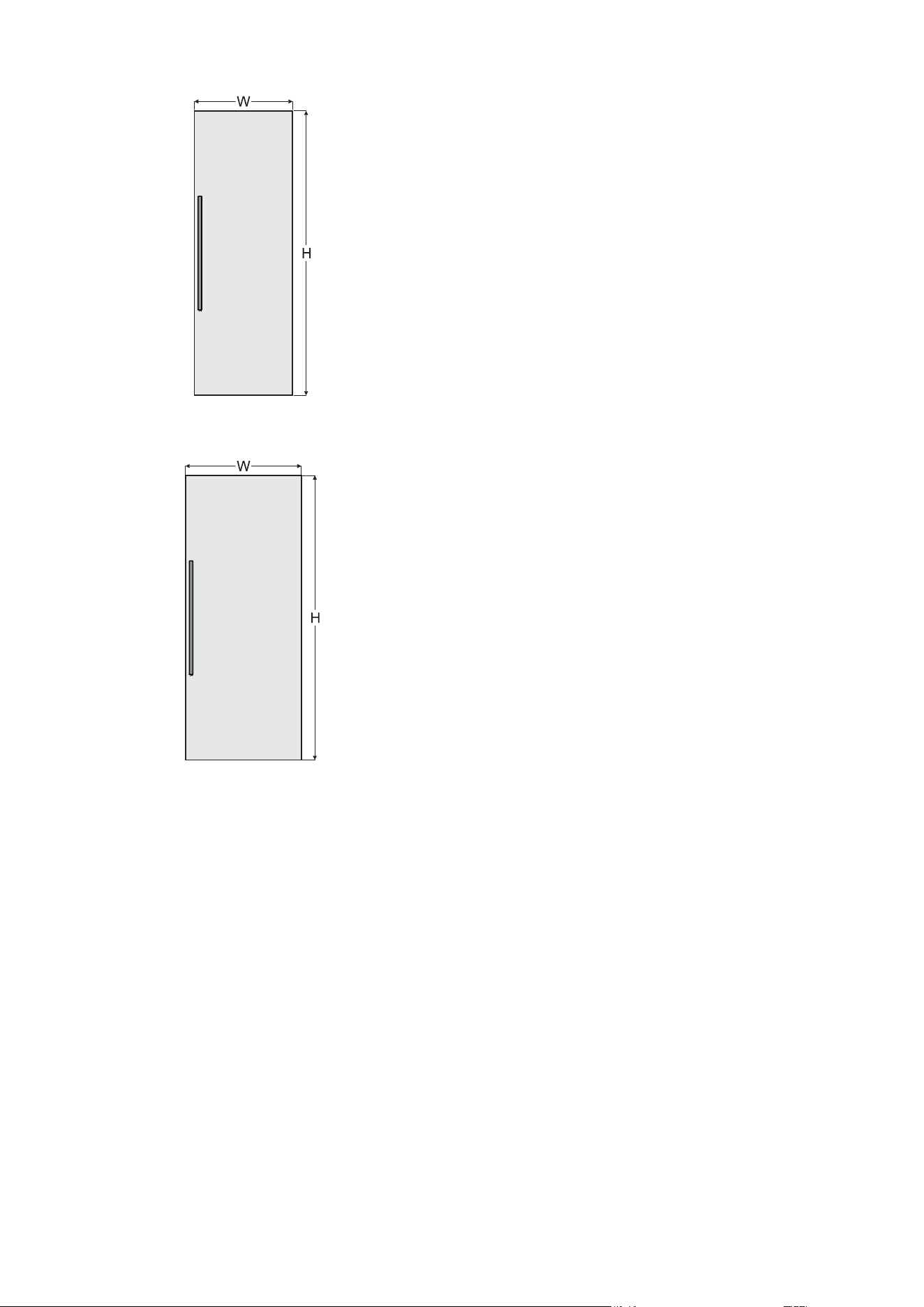
EN
762 mm recess
Internal door panel
H = 2029 mm
W = 756 mm
External door panel
H = 2032 mm plus overlapping of the panel on the top
W = 762 mm plus overlapping of the panel on both sides
Minimum panel thickness = 16 mm
Maximum panel thickness = 25 mm
Maximum panel weight = 35 kg
914 mm recess
Internal door panel
H = 2029 mm
W = 908 mm
External door panel
H = 2032 mm plus overlapping of the panel on the top
W = 914 mm plus overlapping of the panel on both sides
Minimum panel thickness = 16 mm
Maximum panel thickness = 25 mm
Maximum panel weight = 40 kg
32
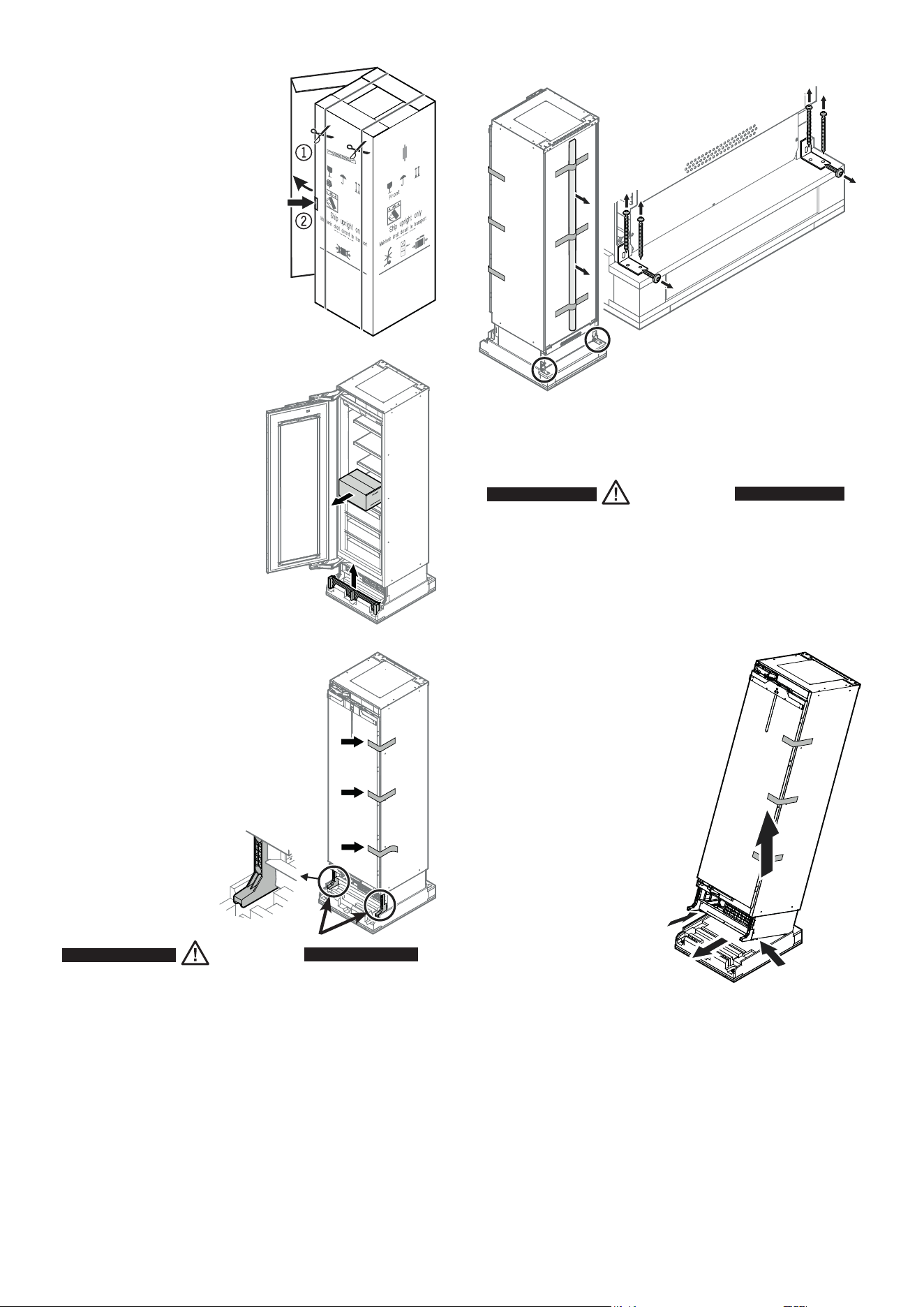
2. Press in the lug, tear or cut
the carton on the edge and
remove it.
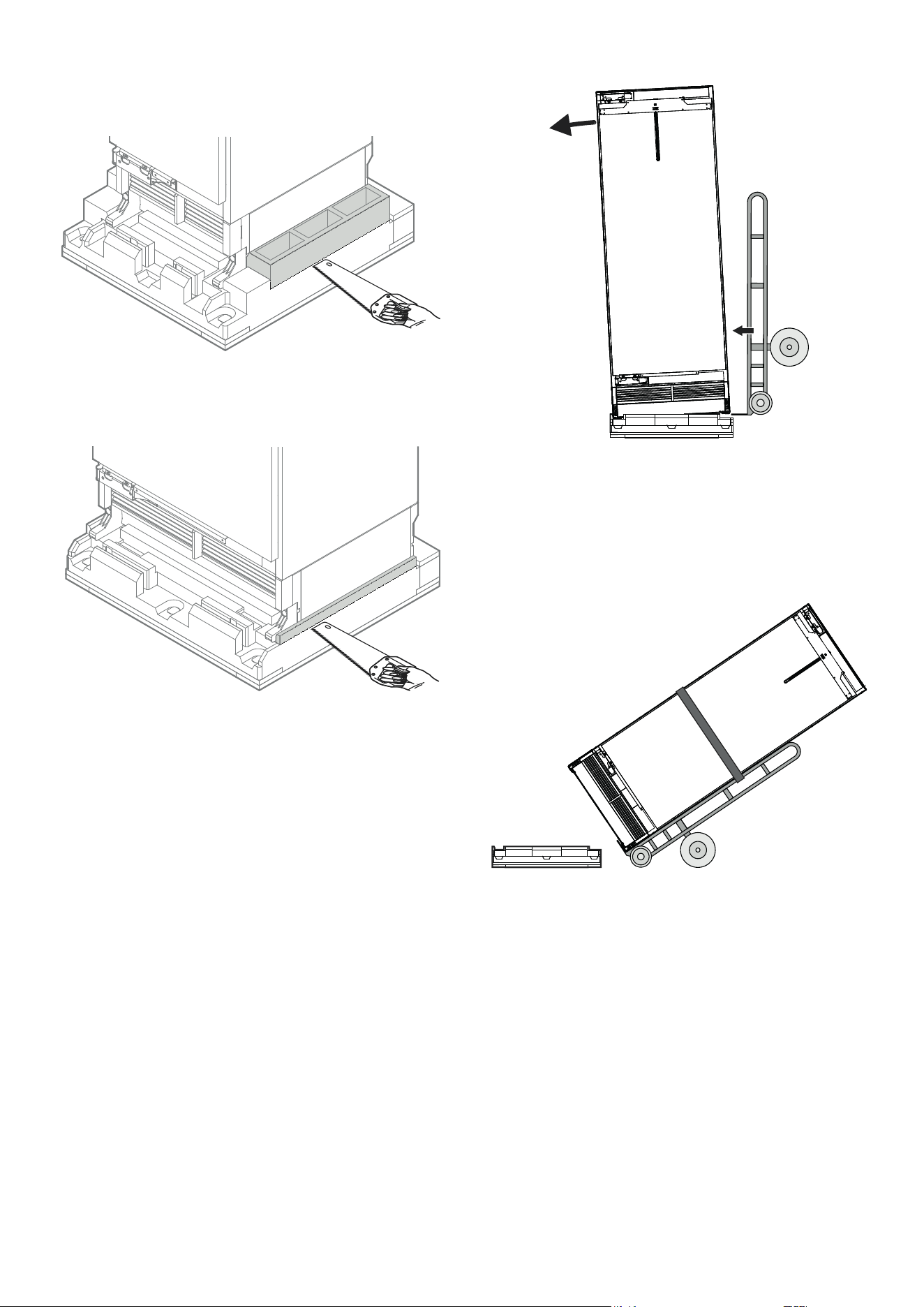
Unpacking
1. Cut the straps and remove
them.
3. Remove all polystyrene packing
material from the sides and top.
4. Remove the box with
mounting accessories.
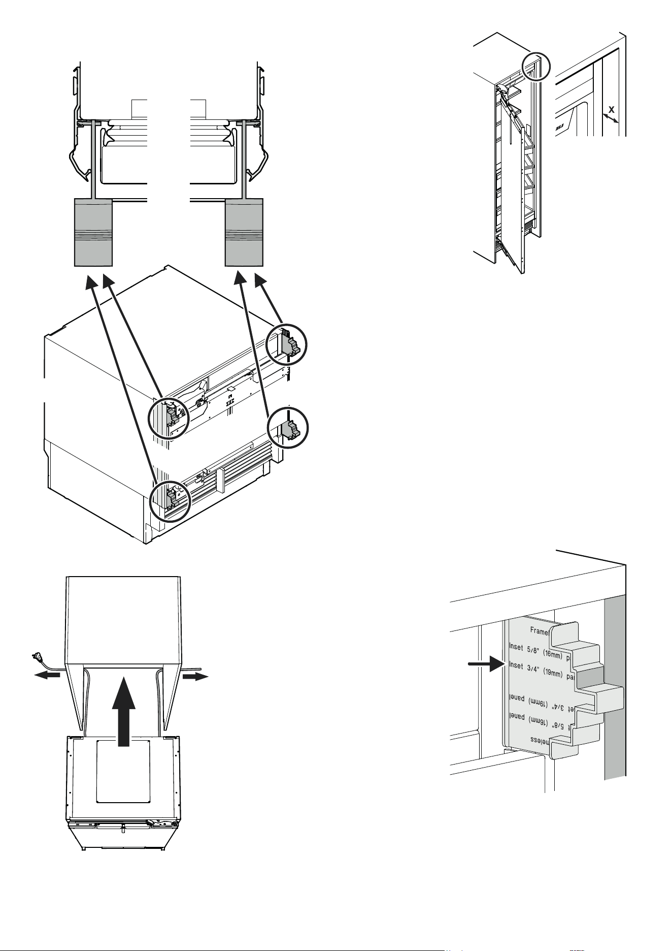
6. Secure the appliance door with tape to
prevent it from being opened accidentally.
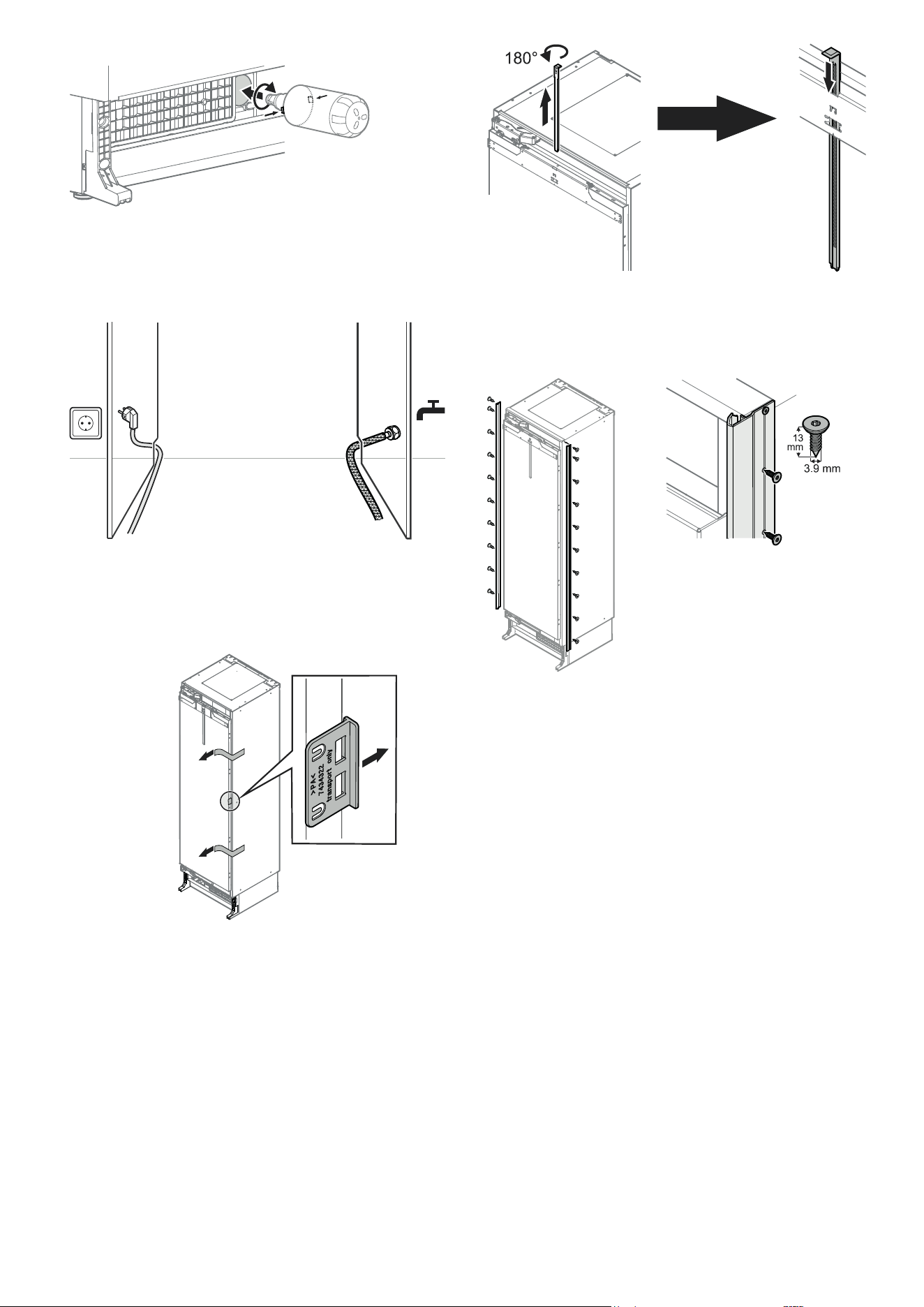
7. Remove the rear transportation
safety components.
Remove the packed cover strips and
support strips from the appliance
rear.
WARNING!
Risk of injury and damage.
Four people are required to safely remove
the appliance from the bottom pallet.
8. One person tilts the appliance backwards
carefully and holds it in place.
9. Two people grasp the appliance
from the bottom and lift. One on
each side.
10. One person removes the pallet.
Place the appliance carefully on the floor.
5. Remove the ventilation grille.
DANGER!
Risk of death or serious injury due to
appliance tipping over.
Do not remove the transportation safety
components before the appliance is in the
recess.
Tx™ 15
Tx™ 15
33
EN
or
Place the appliance carefully on the floor.
Alternative possibility:
Cut off the marked area from the pallet.
Slide a transport dolly between the appliance and packaging.
Tie the appliance to the dolly with straps.
Tilt the appliance onto the dolly.
Tilt the appliance slightly sideways.
34
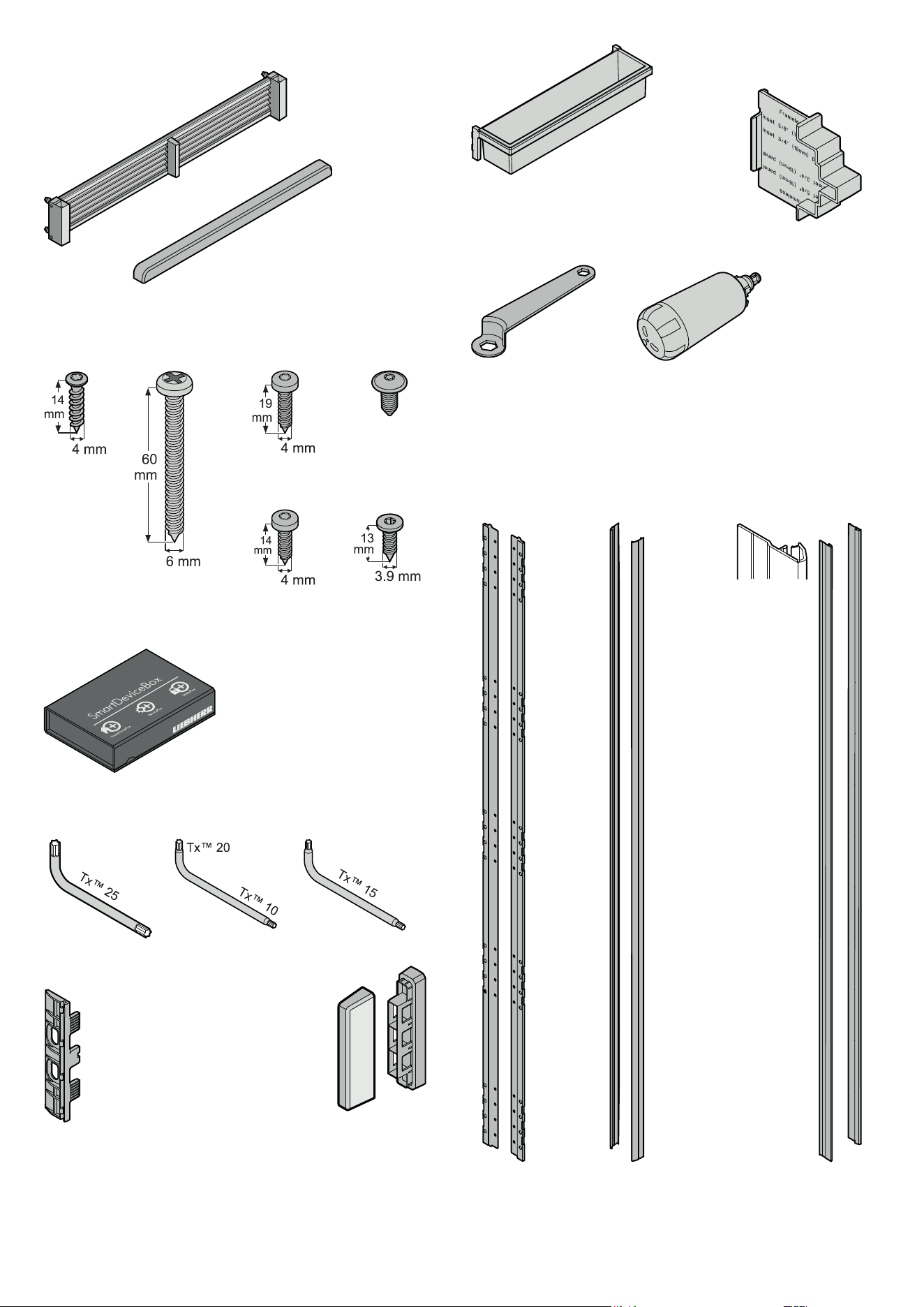
Depth adjustment aid
4 pcs.
Supplied accessories
Retaining screws for installation
30 pcs. 8 pcs. 2 pcs.
20 pcs.
M6 x 12
Ventilation grille
Top cover for the door panel
attachment bracket
10 mm span-
ner
Panel support
10 pcs.
Torx
TM
keys
Divider for ventilation duct
in the plinth area
Door rack
3 pcs.
Water filter
Panel
support
strips
Cover strips for
the gap between
appliance and recess
16 pcs. 20 pcs.
SmartDeviceBox
Includes module for smartphone
connectivity
DO NOT DISCARD!
Forward to appliance user!
Cover strips for
the panel supports
Tx™ 15
Tx™ 15
Tx™ 10
Tx™ 20
Tx™ 15
35
EN
WARNING!
• Theanti-tippingbracketmustbemounted
imperatively to prevent the appliance from
tipping over when the fully stocked door is
opened.
• Besurethatthereisnoplumbingorelectrical
wiring located in this area which could be
damaged during installation.
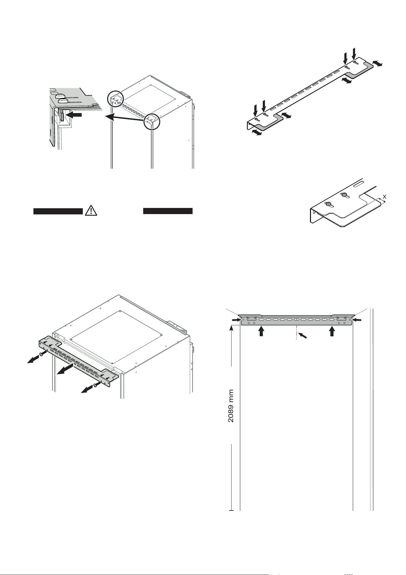
Mounting the anti-tipping device
1. Remove the anti-tipping bracket. The screws are no longer
needed.
Anti-tipping device
2. Mark a centre line on the back wall.
3. Position the anti-tipping bracket at
the stated height and align with the
centre line.
4. Fasten the anti-tipping bracket
through the outer left and right
and any other hole using the eight
6 x 60 screws provided.
Use appropriate plugs for concrete
walls.
External door panel
X = 36 mm
Internal door panel
X = 36 mm minus panel thickness
2.
3.
4.
4.
1.
1.
The anti-tipping device is mounted on the back wall in the recess
at the finished installation height. After the appliance is in the
recess and raised in height, the hook of the anti-tipping bracket
will connect with the appliance top and prevent tipping.
Adjustment of the anti-tipping bracket for use in a
635 mm deep recess
Both base parts of the anti-tipping bracket
must be adjusted for use in a recess
with a depth of 635 mm.
- Loosen the screws.
- Move the base part back or forth.
- Tighten the screws.
If the recess is deeper than 635 mm, a spacer must be mounted
between anti-tipping bracket and wall.
3.
Tx™ 25
Tx™ 25
36
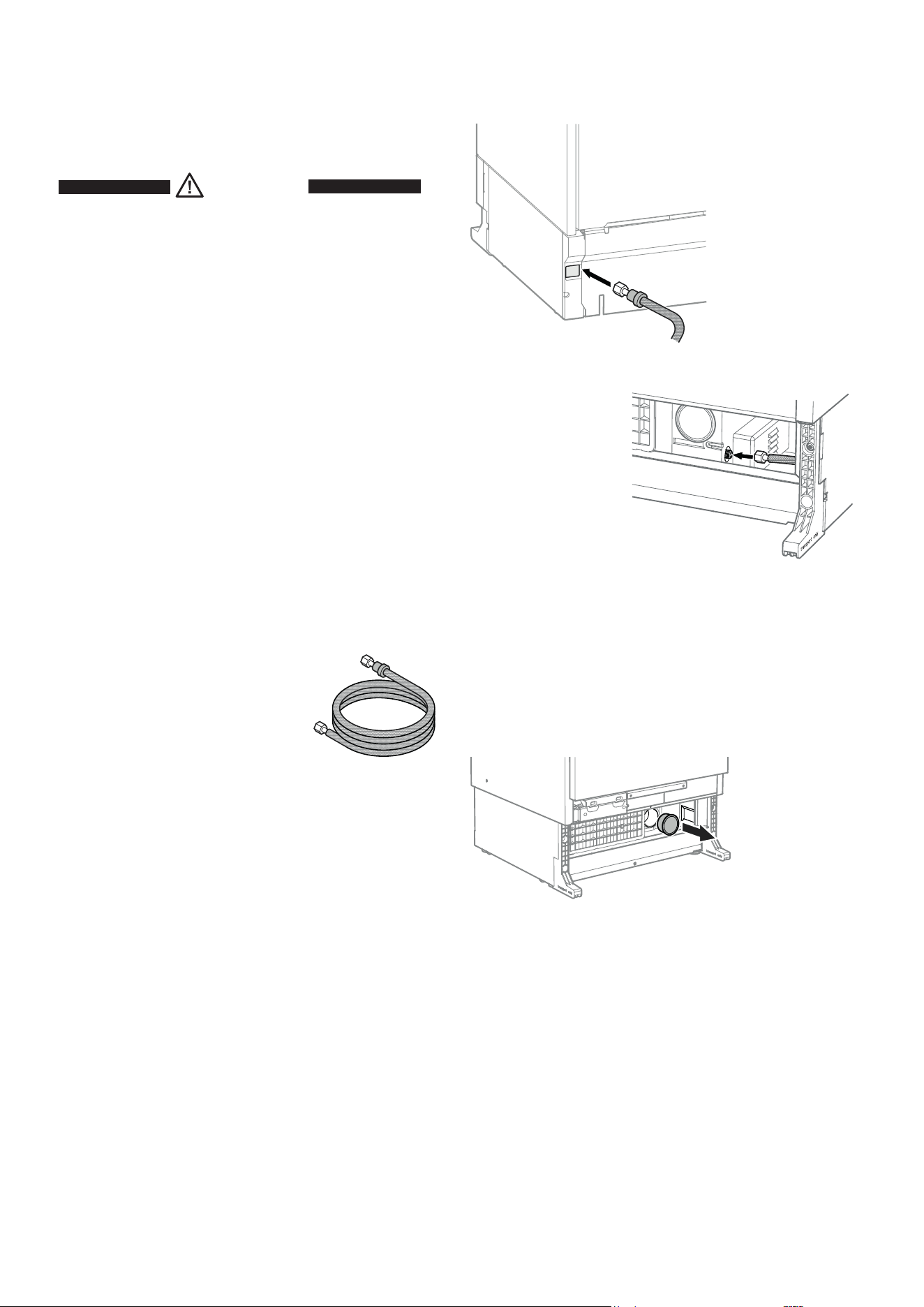
Appliance installation
Move the appliance towards the final position and leave enough
space to work behind.
Remove the cover.
The water supply to the appliance must be
through a cold water pipe that can withstand
the operating pressure and complies with
the hygiene regulations. For this, use the
stainless steel hose supplied (length 3 m).
Pull the water line through
from the rear to the front.
Connect the other end and tighten.
IMPORTANT
Make sure that the connection is fitted with a seal and is
tight.
Safety instructions and warnings for
water
connection
• Do not install the water connection while the appliance is
connected to an electrical socket.
• Theconnectiontothemainswatersupplymayonlybemade
by a trained and licensed plumber.
WARNING!
Connect to potable water supply only.
Water connection requirements
• Thewaterpressuremustbeintherangeof0.28-0.62 MPa
(2.8-6.2 bar).
Failure to meet these requirements may result in IceMaker
malfunction and a water leak that can damage flooring and
surrounding furniture.
• Ashut-offvalvemustbeinstalledbetweenthewaterlineand
the mains water supply. It must be easily accessible so that
the water supply can be stopped immediately if necessary.
IMPORTANT
Do not install the shut-off valve behind the appliance.
IMPORTANT
Do not use any old or already premounted water supply
lines.
37
EN
Insert the water filter as far as it will go with the front
knobs in a horizontal position and turn clockwise
until it snaps in.
Route the mains cable towards
the socket.
Route the water hose towards
the water shut-off valve.
Open the door and re-
move the transportation
safety component.
Remove the tapes.
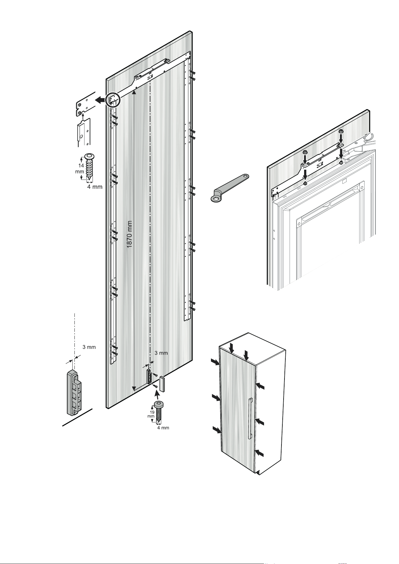
Remove the mounting strip
from the attachment bracket,
turn 180° and insert into the
attachment bracket as far as
it will go.
Apply the appliance cover strips to the
left and right front edge of the appli-
ance housing, align in height with the
appliance top and screw into place. The
strip is transparent so that the designed
attachment holes on the appliance hous-
ing are visible.
IMPORTANT
Complete the installation
before switching on the
appliance.
Tx™ 10
IMPORTANT
Use the correct flat-headed screws,
otherwise the edges of the kitchen
unit will be damaged when sliding
the appliance into the recess.
38
Slide the appliance into the
recess. To avoid damage,
move the mains cable and
the water line at once.
Recess
Top view
Align the appliance in
depth.
X = recess front to appli-
ance housing front (not
cover strip)
Internal 22 mm door panel
X = 66 mm
Internal 19 mm door panel
X = 63 mm
Internal 16 mm door panel
X = 60 mm
External door panel
X = 44 mm
or
with the depth adjustment aid:
The surface of the depth adjustment
aid must be flush with the surface of the
recess (example shows 19 mm).
Mounting the depth adjustment aid
into the cover strips
39
EN
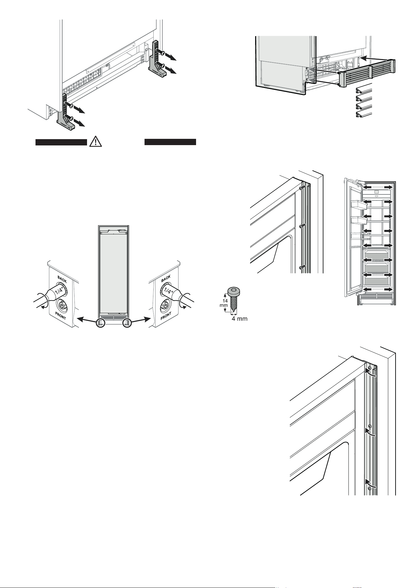
Remove the transportation safety
components using the Torx 25 key.
Mount the ventilation grille with the grille seg-
ments tilted down.
DANGER!
Risk of death or serious injury due to
appliance tipping.
Do not open the appliance door before the
height adjustment is finished and the anti-
tipping bracket supports the appliance.
Fasten the appliance in the
recess through the appliance
cover strips using eight 4 x 14
screws for each side.
Close the front part of the appliance
cover strips.
Raise the appliance evenly by turning the screws serially until
the appliance top back touches the anti-tipping bracket (lift ap-
prox. 6.5 mm).
IMPORTANT
When turning the screws with an electric screwdriver,
please make absolutely sure that:
Maximum rotation speed = 400 rpm
Maximum torque = 1 Nm
Failure to follow this instruction will result in
damage to the height adjustment.
Right
Turn anticlockwise to raise
the appliance.
Left
Turn clockwise to raise the
appliance.
Remove the depth adjustment aid before fastening the appliance
in the recess.
Tx™ 15
40
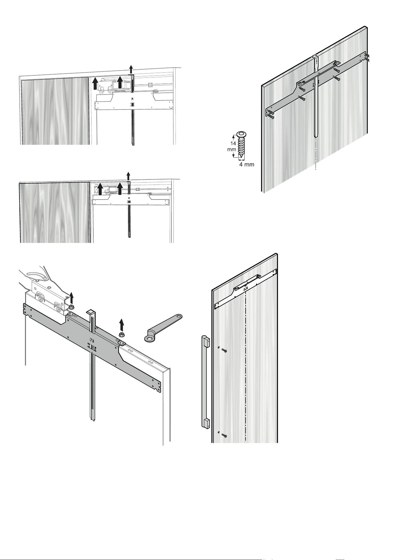
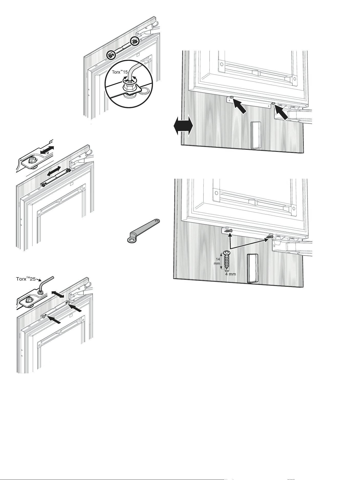
Push the mounting strip upwards.
The bottom edge of the mounting strip must be aligned with the
top edge of the adjacent unit door.
Internal door panel
External door panel
Open the door.
Unscrew the attachment bracket with
the mounting strip. To do so, use the ring
spanner provided.
IMPORTANT
When removing, ensure that the mounting
strip does not move.
Position the attachment bracket in the middle of the door
panel, align horizontally and secure to the door panel
using eight 4 x 14 screws.
IMPORTANT
Door handles should be mounted now because the panel
support strips will cover the attachment holes.
Only use countersunk screws
for handle mounting.
The holes should be counter-
sunk.
The screw heads should be flush
with the panel.
Tx™ 15
41
EN
Open the appliance door.
Place the door panel on the top adjusting screws and
align in the centre.
Screw the hex nuts onto the adjusting bolts
and tighten.
Use the 10 mm spanner provided.
Close the door and check the position of the door panel.
IMPORTANT
If the door has to be limited to a 90° opening angle, it must
be done before the panel is mounted onto the appliance
door. See chapter "Important note for changing over
door hinges or limiting the door opening angle to
90°" on page 44.
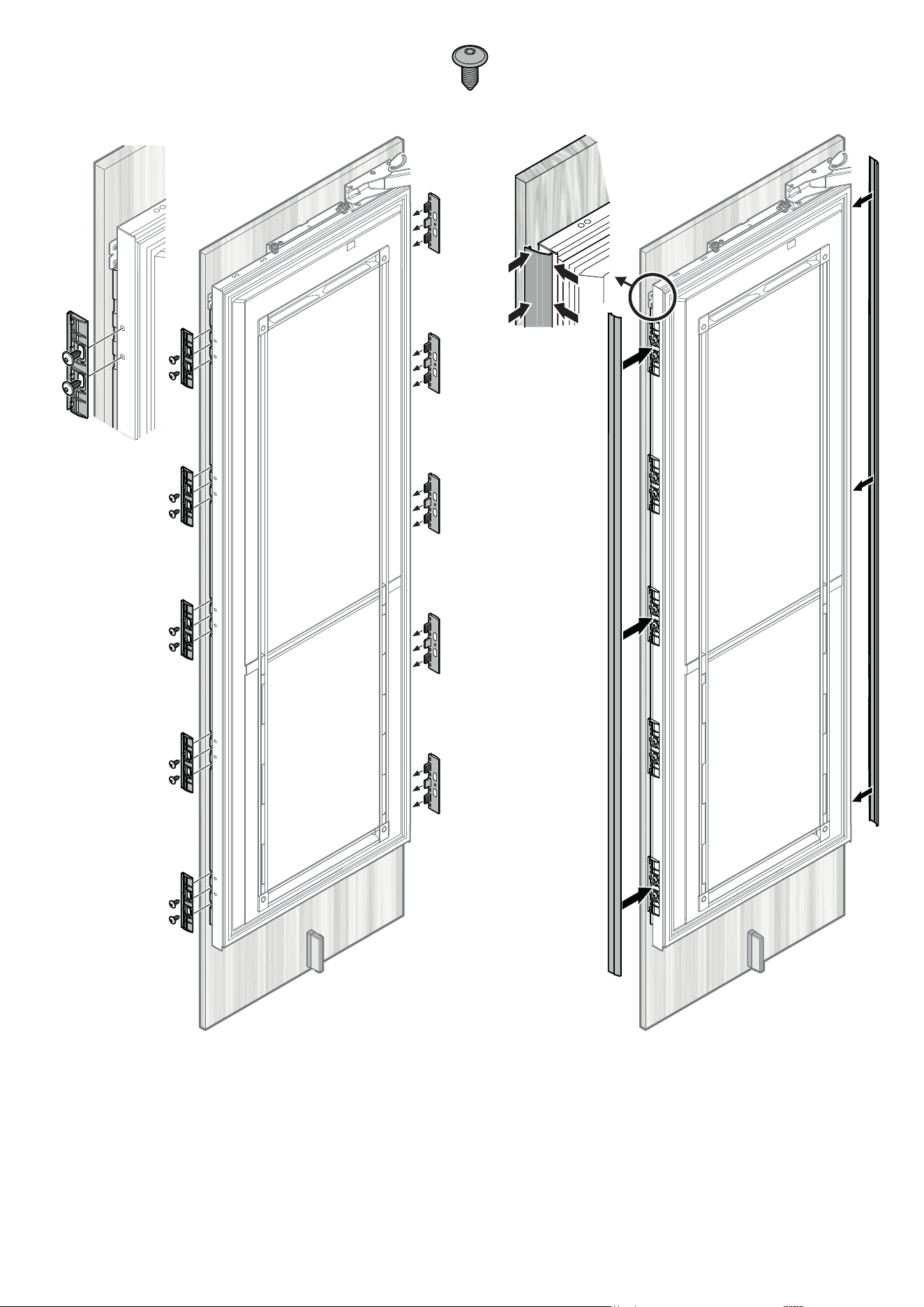
Position the panel support strips with the top lug in the
cut-out of the top attachment bracket.
Align the strips parallel to the side edge of the panel
and screw into place with ten 4 x 14 screws.
Mount the ventilation duct divider with two 4 x 19
screws.
Click on the cover.
IMPORTANT
After a certain time and
loading, it may be necessary
to readjust the door.
Tx™ 15
Tx™ 15
42
Align the panel horizon-
tally with the long slots in
the attachment bracket.
Tighten the hex nuts.
Use the 10 mm spanner
provided.
Align the panel in its vertical posi-
tion if necessary.
Align the panel in its depth.
Loosen the screws, align
the panel and tighten the
screws.
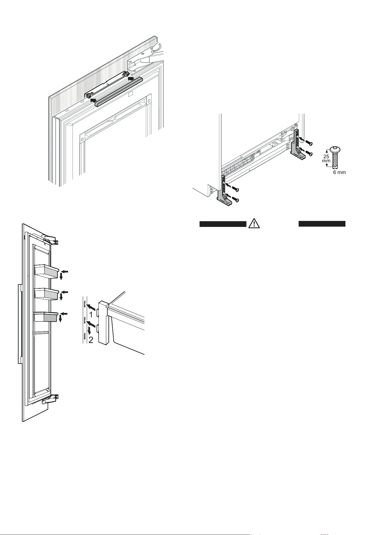
Secure the panel through the bottom attachment bracket with
two 4 x 14 screws.
Align the panel in its depth at the bottom.
Loosen the screws, align the panel and tighten the screws. Use
the Torx 20 key provided.
Loosen the hex nuts and
turn the adusting bolts with
the Torx 15 key provided.
Tx™ 15
43
EN
Hook the door cover strips to the front of the supports and
snap in at the back.
Insert the panel supports between panel and appliance door
and screw into place with two M6 x 12 screws each.
Tx™ 20
44
Click cover into place.
Insert the door racks.
Insert the hooks of the rack into the open-
ings of the clip-in strip at the desired height
and push down.
IMPORTANT
Be sure each door rack is fixed
properly in the clip-in strip.
Important note for changing over door hinges
or limiting the door opening angle to 90°
Changing the door hinges or limiting the door opening angle to
90° should only be carried out by a trained expert.
The door hinges are fitted with strong closing springs. If the hinge
accidentally snaps shut, this can lead to serious injury.
The door itself is very heavy. Do not try to remove the door yourself.
Contact the Liebherr customer service department for more
information. See contact details on the back of this manual.
Please note in case of removing appliance
from the recess
If the appliance has to be removed from the recess again, please
make sure you take account of the following:
1. Remove the door panel.
2. Lower the appliance using the height adjustment unit.
DANGER!
Risk of death or serious injury due to the
appliance tipping over.
Do not remove the appliance without the
mounted transportation safety components.
3. Mount the transportation safety compo-
nents with two screws for each support
using a Torx 25 key.

45
EN
Liebherr Hausgeräte Lienz GmbH
Dr.-Hans-Liebherr-Strasse 1
A-9900 Lienz
Österreich
www.liebherr.com
*708574500*