
Contact Us!
Do NOT return this item.
Contact our friendly customer service department for
help first.
P
lease contact us via Amazon Message or
customer service number: 213-4467172 or
661-4358826
Before You Start
Please read all instructions carefully.
Retain instructions for future reference.
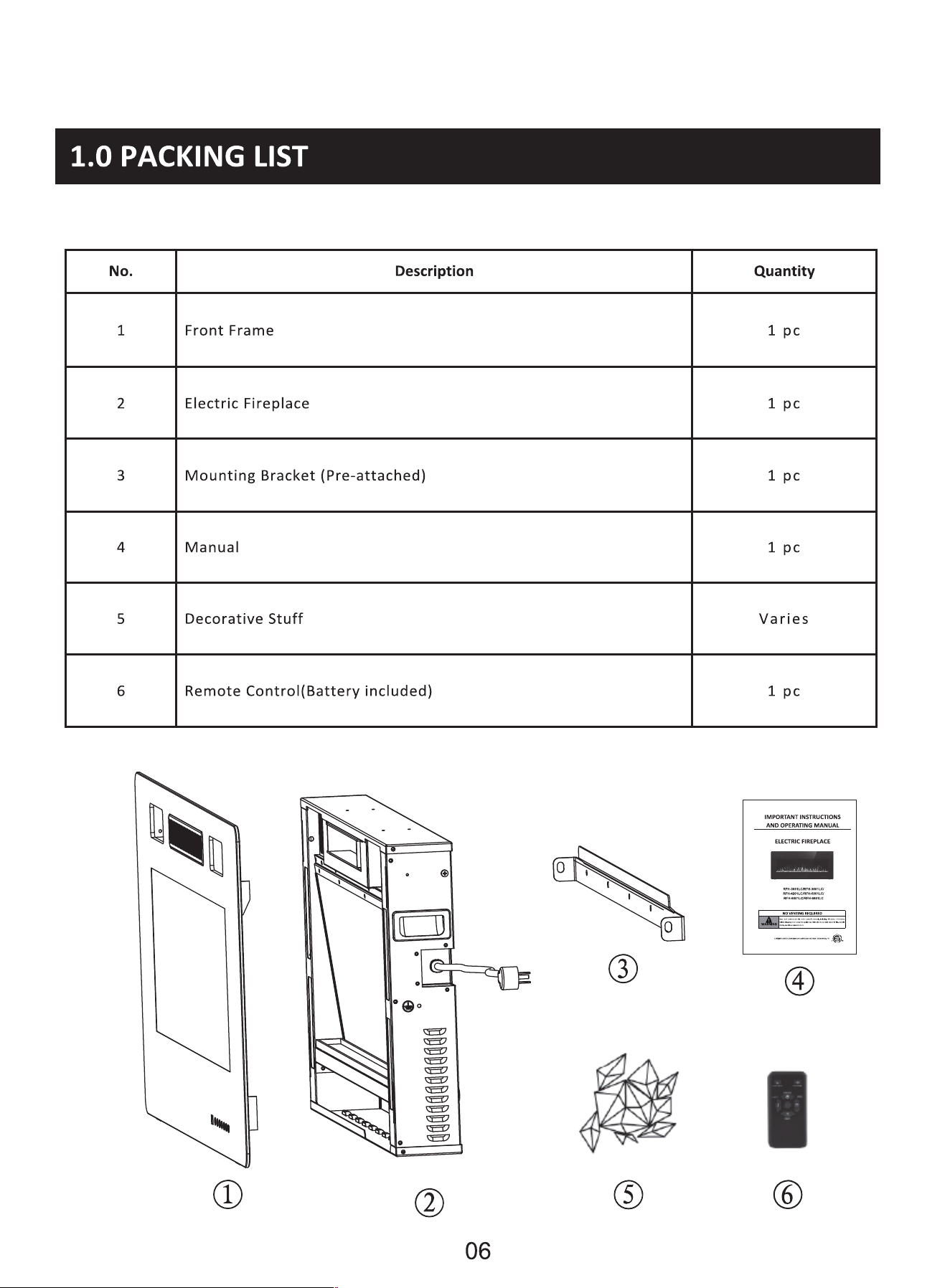
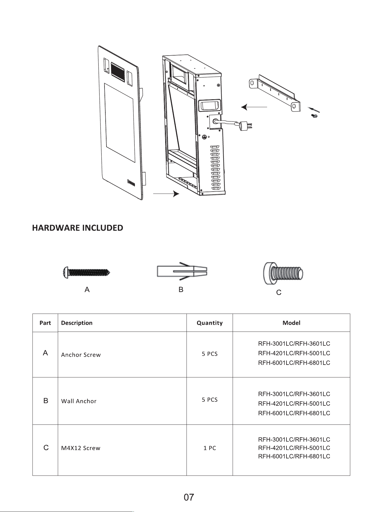
Separate and count all parts and hardware .
Read through each step carefully and follow the proper order.
We recommend that, where possible, all items are assembled near to the
area in which they will be placed in use, to avoid moving the product
unnecessarily once assembled.
Always place the product on a flat, steady and stable surface.
Keep all small parts and packaging materials for this product away from
babies and children as they potentially pose a serious choking hazard.

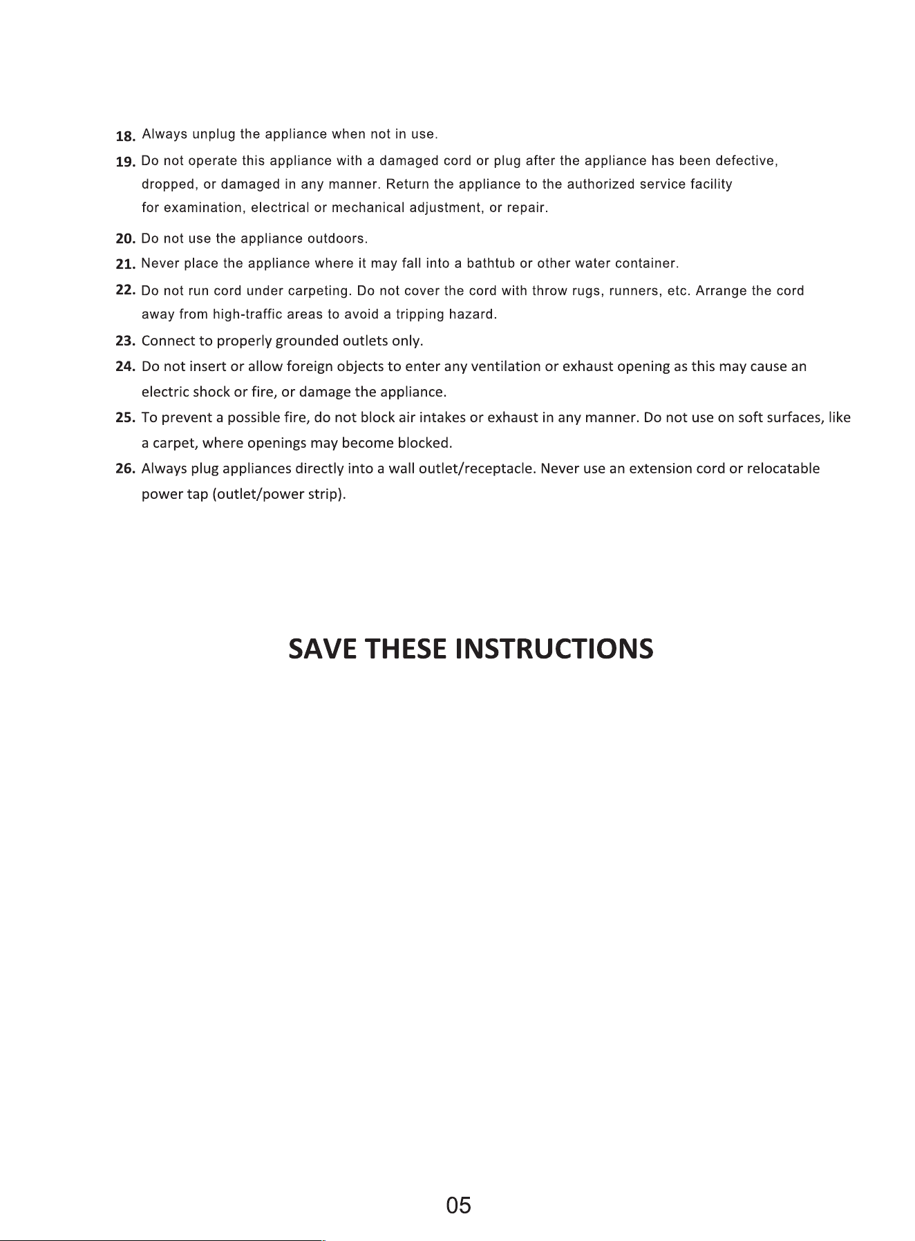
IMPORTANT SAFETY INSTRUCTIONS
A WARNING
These instructions should be carefully read before installation and retained by the user. The booklet must be kept
and delivered to the new user in case of disposal of the heater. The Manufacturer reserves the right to vary the
features of the product without prior notice. The technical data are indicative only.
1. THIS APPLIANCE IS HOT WHEN OPERATED AND CAN CAUSE SEVERE BURNS IF TOUCHED.
2. Do not operate the appliance before reading and understanding operating instructions. Failure to operate the
appliance according to operating instructions could cause fire or injury.
3. Keep combustible materials, such as furniture, pillows, bedding, papers, clothes and curtains at least 3 feet
(0.9 m) from the front of this appliance and keep away from the sides and the rear. WARNING: In order to
avoid overheating, do not cover the heater. The clearance may be inadequate when installed in a
Recreational Vehicle with the slide-out closed.
4. Risk of burns. Power to the appliance should be turned o, and the appliance should be allowed to cool before servicing.
To disconnect the appliance from the power supply, turn o the controls, and then remove the plug from the outlet.
5. Do not install damaged, incomplete or substitute components.
6. Young children should be carefully supervised when they are in the same room with the appliance.
Toddlers, young children, and others may be susceptible to accidental contact burns.
7. To prevent accidental swallowing, media bed kits should be kept away from children and infants.
8. The remote control contains small batteries. Keep them away from children. If swallowed, seek medical assistance
immediately.
9. Do not install battery backwards, charge, put it in fire or mix it with used or other battery types-may explode
or leak causing injury.
10. E
nsure that you have incorporated adequate safety measures to protect infants/toddlers from touching hot
surfaces.
11. It is imperative that the control compartments, circulating blower and its passageway in the appliance are
kept clean. The appliance should be inspected before use and at least annually by a qualified service person.
12. Under no circumstances should this appliance be modified.
13. Do not use this appliance if any part has been in contact with water. Immediately call a qualified service
technician to inspect the appliance and to replace any part of the control system which has been in contact
with water.
14. Do not operate the appliance with the glass door removed, cracked or broken. Replacement of the glass
should be done by a licensed or qualified service person.
15. Do not strike or slam shut the appliance's glass door.
16. Keep the packaging material out of reach of children and dispose of the material in a safe manner. As with all
plastic bags, these are not toys and should be kept away from children and infants.
17. Servicing should be done only while the appliance is disconnected from the power supply circuit.
04
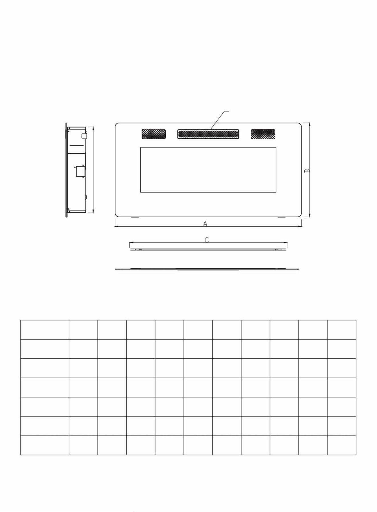
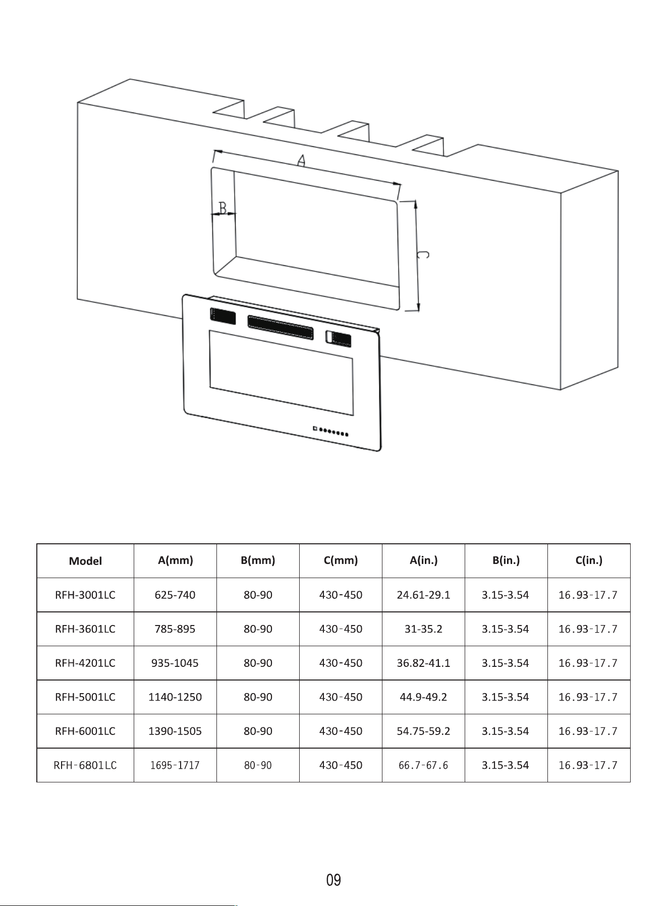
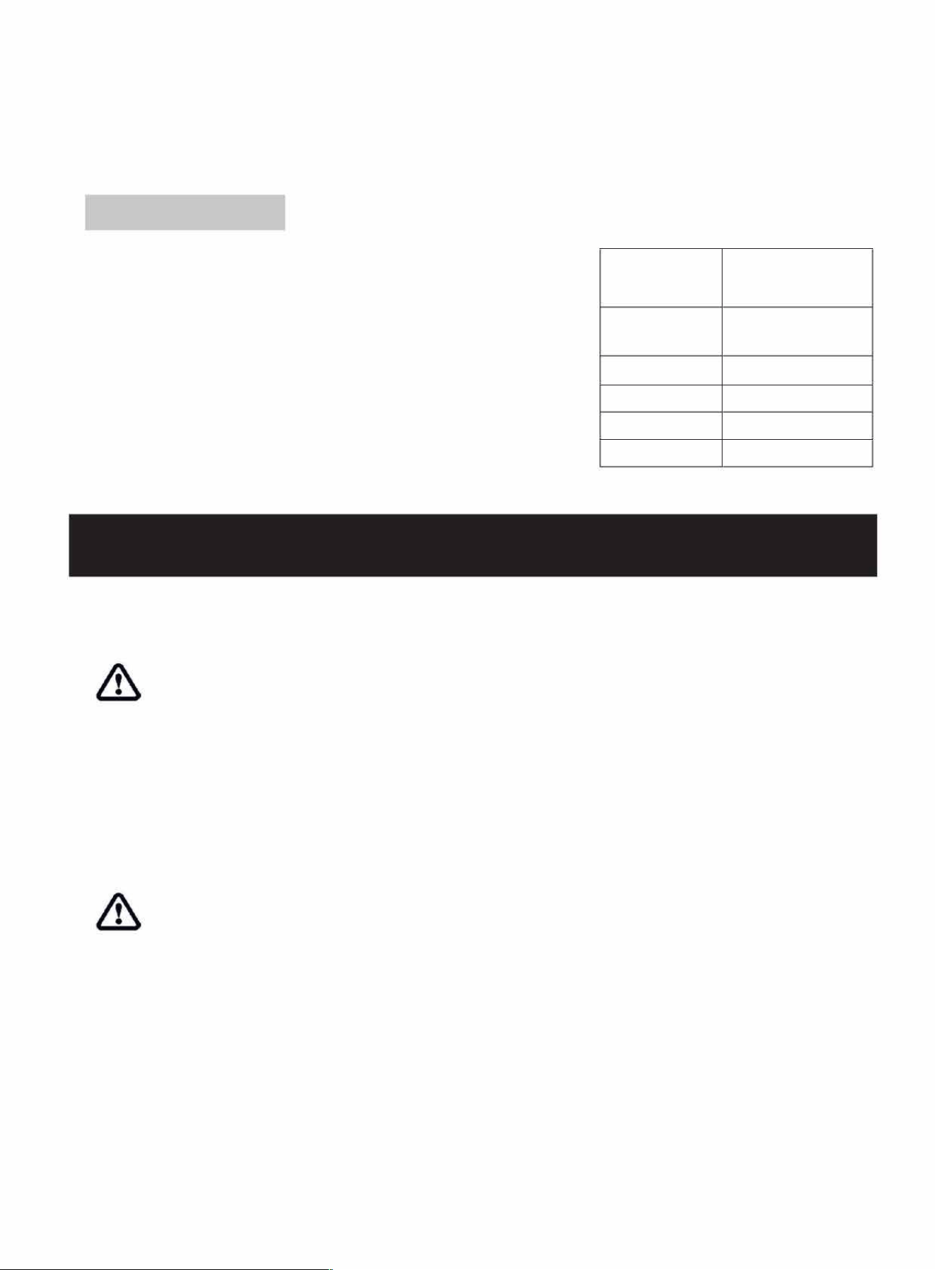
1.1 DIMENSIONS
HEAT VENTS
SIDE
CDDN'T COVER)
e
II
•
o
@
w
••
=
=
=
=
=
=
=
=
=
=
□ @@®®@®
1 I 3
TOP
Model
A(mm) B(mm)
C(mm)
D(mm) E(mm) A(in.) B(in.)
C(in.)
D(in.) E(in.)
RFH-3001LC
762 460
618
98
420 30
18.11
24.33
3.86
16.54
RFH-3601LC
914
460
771 98
420
36
18.11
30.35
3.86
16.54
RFH-4201LC 1066 460 922
98
420
42
18.11
36.30
3.86 16.54
RFH-5001LC
1270
460
1126
98
420
so
18.11
44.33
3.86
16.54
RFH-6001LC
1524
460
1380
98
420
60
18.11
54.33
3.86
16.54
RFH-6801LC
1727
460
1583
98
420
68
18.11
62.32
3.86
16.54
08
NOTE:
* Please leave enough space to place the power cord on the right side of the fireplace.
LISTING APPROVALS
This appliance has been tested in accordance with the ETL Standards for
fixed and location-dedicated electric room appliances in the United States
and Canada. If you need assistance during installation, please contact your
local dealer.
NOTE: This appliance must be electrically wired and grounded in
accordance with local or, in the absence of local, with National
Electric Code ANSI/NFPA 70-latest edition in the United States
or the Canadian Electric Code and ETL in Canada.
2.0 ELECTRICAL INSTALLATION NOTES
2.1 GENERAL INSTRUCTIONS
Model No.
Description
Voltage
s
Amps
BTUs
RFH-3001 LC/RFH-3601 LC/
RFH-4201 LC/RFH-5001 LC/
RFH-6001 LC/RFH-6801 LC
Wall-mount, recessed
12OVAC
Max 15OOW
12.SAMP
SlOOBTU
CAUTION - Some parts of this product can become very hot and cause burns. Particular attention has to
be given where children and vulnerable people are present.
A. Prior to plugging your appliance into an electrical outlet, verify that the house circuit breakers for the outlet are
on.
B.The appliance may emit a slight, harmless odor when first used. This odor is normal and caused by the
initial heating of internal appliance elements, and the odor will not occur again.
C. If your appliance does not emit heat, consult the operation section of this manual for further information.
D. Use with an ETL or UL certified surge protector.
RISK OF FIRE! THE POWER CORD MUST NOT BE PINCHED AGAINST A SHARP EDGE. SECURE CORD TO
AVOID TRIPPING OR SNAGGING TO REDUCE THE RISK OF FIRE, ELECTRIC SHOCK OR PERSONAL INJURY.
DO NOT RUN CORD UNDER CARPETING. DO NOT COVER CORD WITH THROW RUGS, RUNNERS, ETC.
ARRANGE THE CORD AWAY FROM HIGH-TRAFFIC AREAS TO AVOID A TRIPPING HAZARD.
RISK OF FIRE. TO PREVENT A POSSIBLE FIRE, DO NOT BLOCK AIR INTAKE OR EXHAUST IN ANY MANNER. DO NOT USE
IT ON SOFT SURFACES WHERE OPENINGS MAY BECOME BLOCKED.
RISK OF FIRE. DO NOT BLOW OR PLACE INSULATION AGAINST THE APPLIANCE.
THIS ELECTRIC APPLIANCE IS TESTED AND LISTED FOR USE ONLY WITH THE APPROVED OPTIONAL ACCESSORIES.USE
OF OPTIONAL ACCESSORIES NOT SPECIFICALLY TESTED FOR THIS ELECTRIC APPLIANCE COULD VOID THE WARRANTY
AND/OR RESULT IN A SAFETY HAZARD.
10
IF THE INFORMATION IN THESE INSTRUCTIONS IS NOT FOLLOWED EXACTLY, A FIRE MAY RESULT CAUSING PROPERTY
DAMAGE, PERSONAL INJURY OR DEATH. DO NOT STORE OR USE GASOLINE OR OTHER FLAMMABLE VAPORS IN THE
VICINITY OF THIS OR ANY OTHER APPLIANCE.
THIS APPLIANCE IS HEAVY. IT IS HIGHLY RECOMMENDED THAT TWO PEOPLE INSTALL THIS APPLIANCE.
HEATER VENTS ON THE ELECTRIC APPLIANCE CANNOT, IN ANY WAY, BE COVERED. AS IT MAY CREATE A FIRE
HAZARD.
Follow all National and local electrical codes.
1.
The heaters should be installed only using the mounting brackets we provided if you want to mount them.
2.
The heater must not be recessed in the ceiling. There must be enough space around the top of the heater to
ensure adequate ventilation.
3.
The heater should be at least 60cm/24 inches away from any surrounding walls.
4.
A distance of at least 90cm/36 inches should always be left in front of the heaters to ensure safety.
5.
The heater must be located neither directly below nor in front of a socket-outlet.
6.
The heater must be installed to prevent any control switches from being touched by anyone who is in the
shower or bath.
7.
Make sure that there is no possibility of inflammable material, combustible material or curtains coming into
contact with the heater, there is a risk of fire if this happens.
8.
DO NOT LEAVE THE HEATER UNAENDED DURING USE.
3.0 INSTALLATION INSTRUCTIONS
3.1 UNPACKING AND TESTING APPLIANCE WALL
Carefully remove the appliance from the box. Prior to installing the appliance, test to make sure the appliance
operates properly by plugging the power supply cord into a conveniently located 120 Volt grounded outlet.
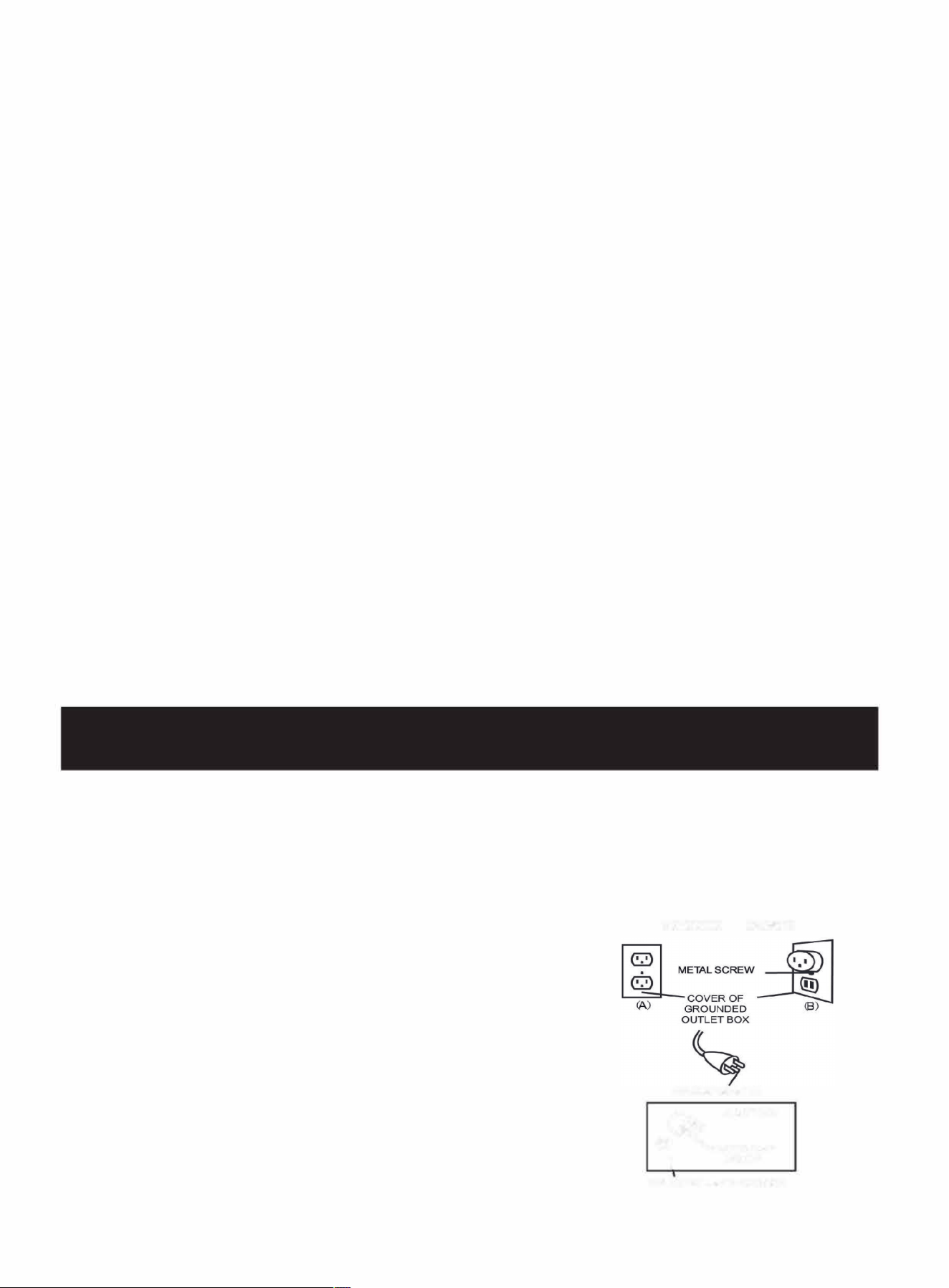
3.2 GROUNDING APPLIANCE
This appliance is for use on 120 Volts. The cord has a plug as shown in (A). An
adapter as shown in (C) is available for connecting three-blade grounding type
plugs to two-slot receptacles. The green grounding lug extending from the
adapter must be connected to a permanent ground such as a properly
grounded outlet box. The adapter should not be used if a three-slot grounded
receptacle is available.
To disconnect the appliance, turn off the controls, then remove the plug from the outlet.
11
GROUNDING
MEODS
GROUNDING PIN
ADAPTER
C�GROUNDING
\
MEANS
NOT LOWED IN CANADA
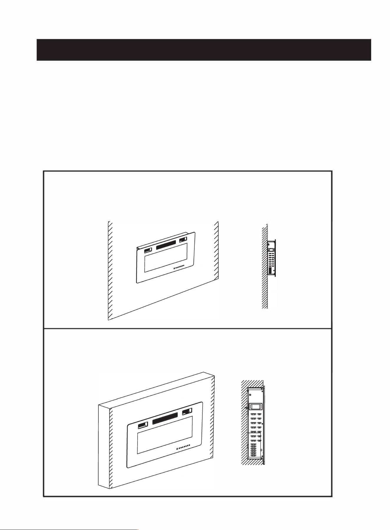
3.3 ASSEMBLY
The fireplace can be installed with 2 options:
1.Wall hanging with provided mounting bracket.
2.Built-in construction (in-wall recessed).
Follow the installation instructions below based on installation preference.
Opon 1:
Wall Hanging ...... page
1
3
-1
6
Opon 2:
Built in Construcon ...... page
17-1
9
12
Installation - Wall Hanging
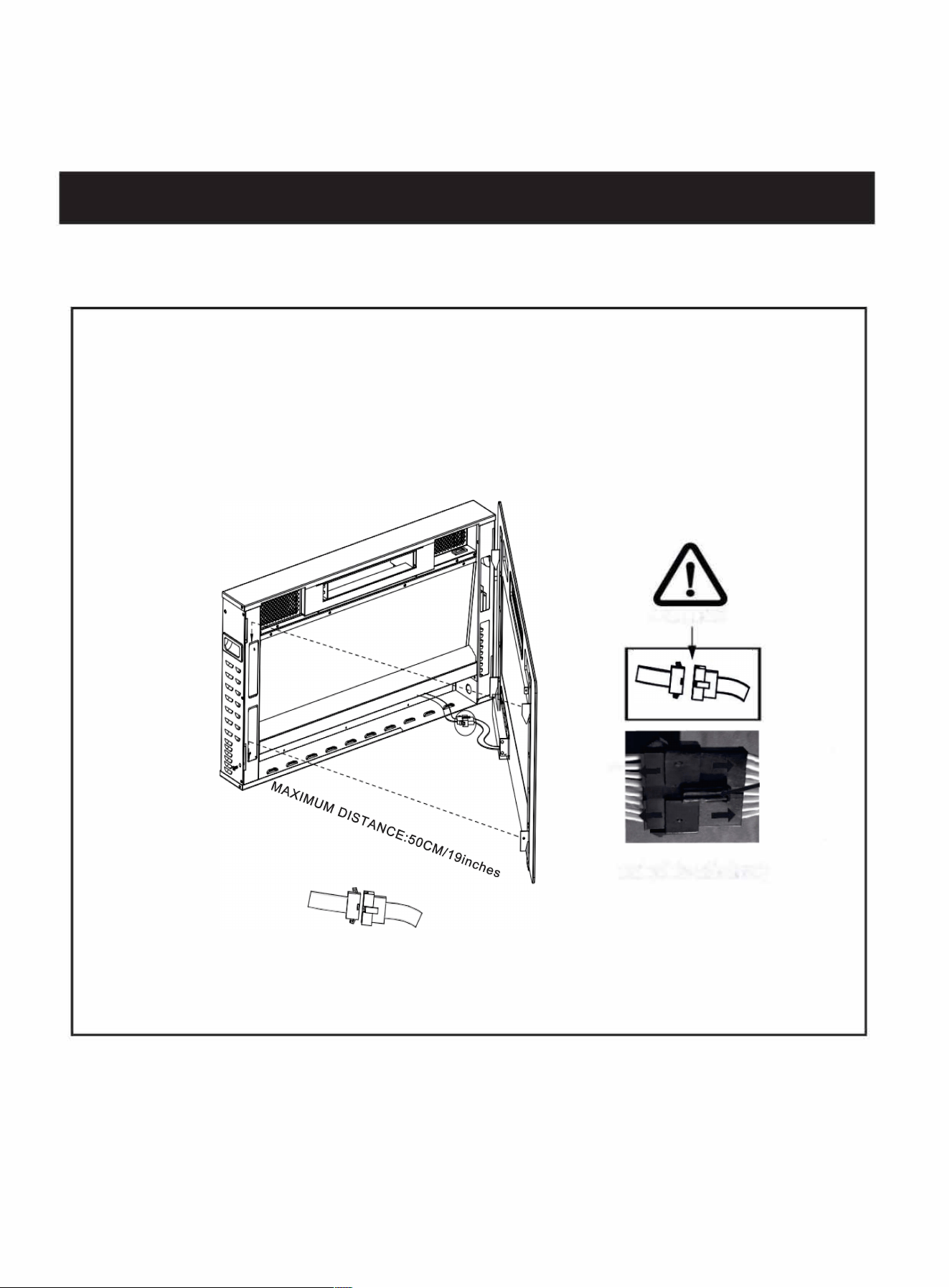
Step 1. Removing the Glass Frame
- Remove the fixed screw in the lower-left corner (Do not discard it)
- Lift the glass frame 1-2cm vertically. Then the entire glass frame can be removed from the front.
-Take the glass frame 0.4-0.8 inches away from the appliance, and pull out the FFC connector with the
help of others or put the glass panel down on the ground before complete separation.
m
13
UTION
Press this
-
button
nt pull e ble dir�
and pull
out the
FFC
connector
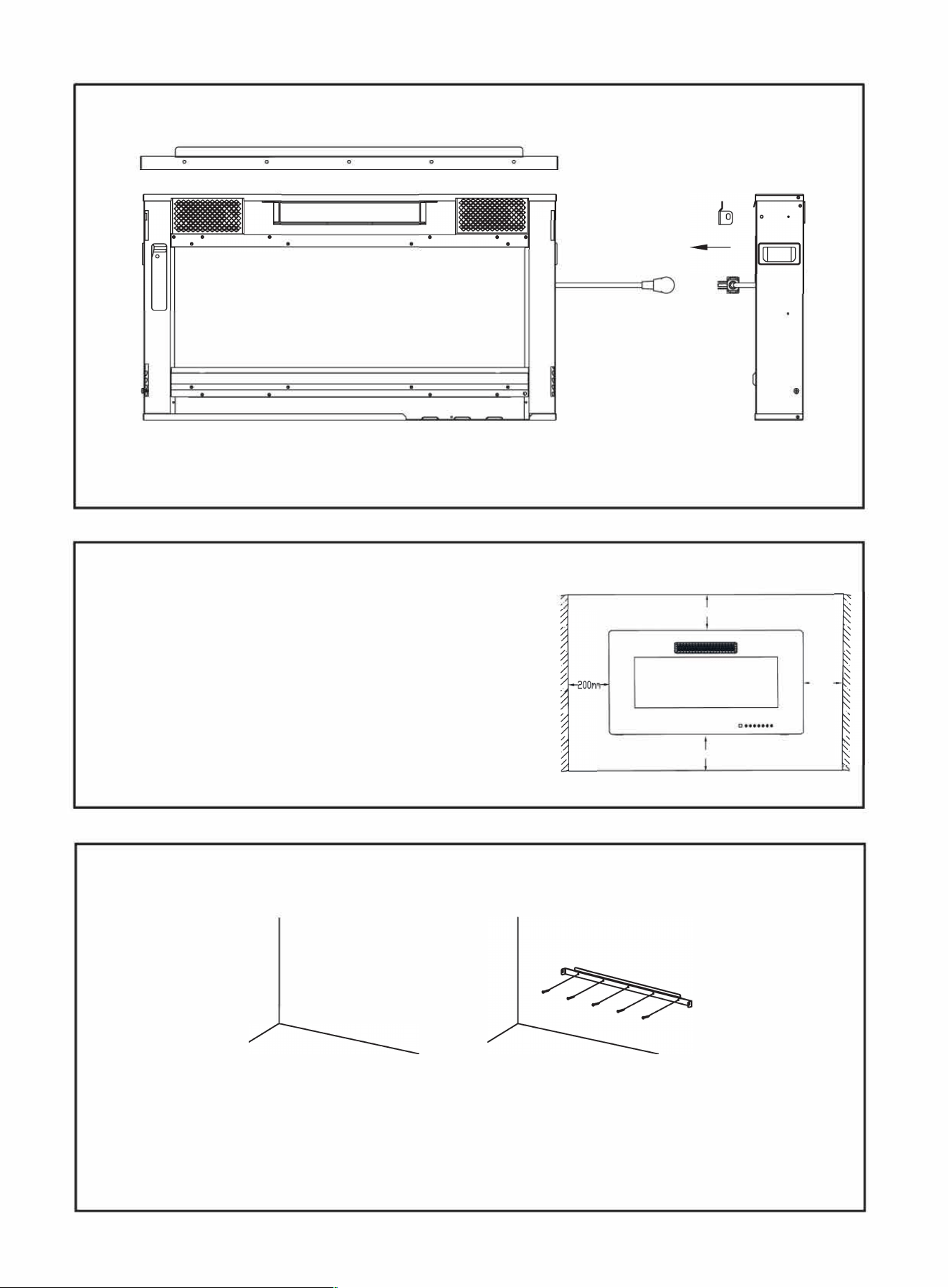
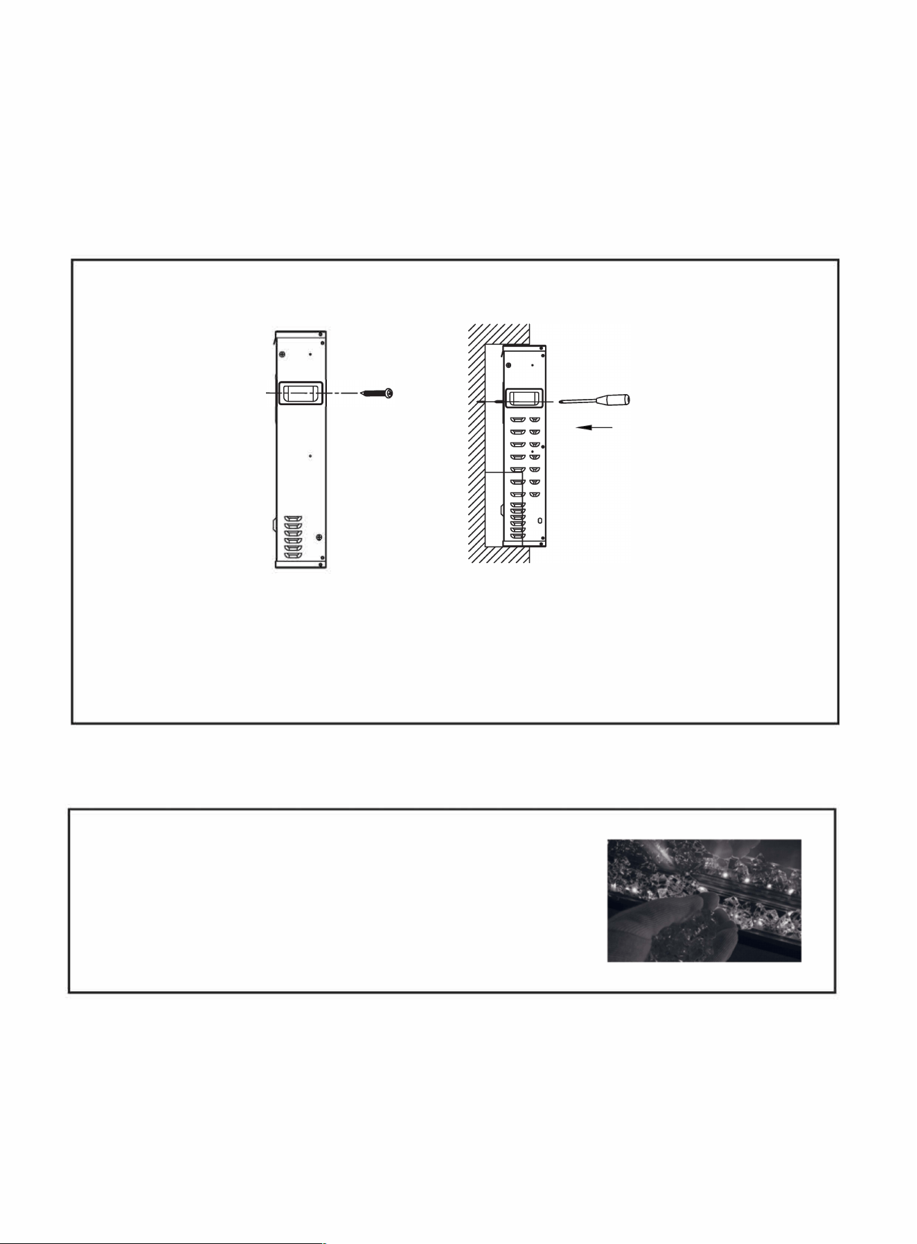
Step 2. Removing the Mounting Bracket
---
�
M5X12
==
==
==·
�
�
==
==
==
==
=
=
=
=
=
=
.
- Unscrew the two screws by Phillips screwdriver from both ends (Do not discard them), then remove the
pre-attached mounting bracket.
Step 3. Choosing a Wall Location
- Find a safe location. Minimum clearance between the ceiling
and the mantel must be at least 8 inches (200mm); minimum
clearance from the front must be at least 3 feet (900 mm).
Choose a location near an outlet so an extension cord is not required.
Note: DO NOT position the unit directly below a power outlet.
See Safety Information on pages 2 and 3 for more warnings
about placement, installation, and use of this product.
200MM
200MM
Step 4. Drilling the Holes and
A
ttaching the Mounting Bracket
- Use a level to align the bracket and mark the holes which need to be drilled with a pencil.
- Drill 3-10 (according to the model you have bought) 75 in. (7mm) holes in the wall.
- Insert the wall anchors into the holes by using a hammer.
200MM
- Attach the mounting bracket to the wall by fastening the Anchor Screws (PartA) into the wall anchors (Part
B
).
14
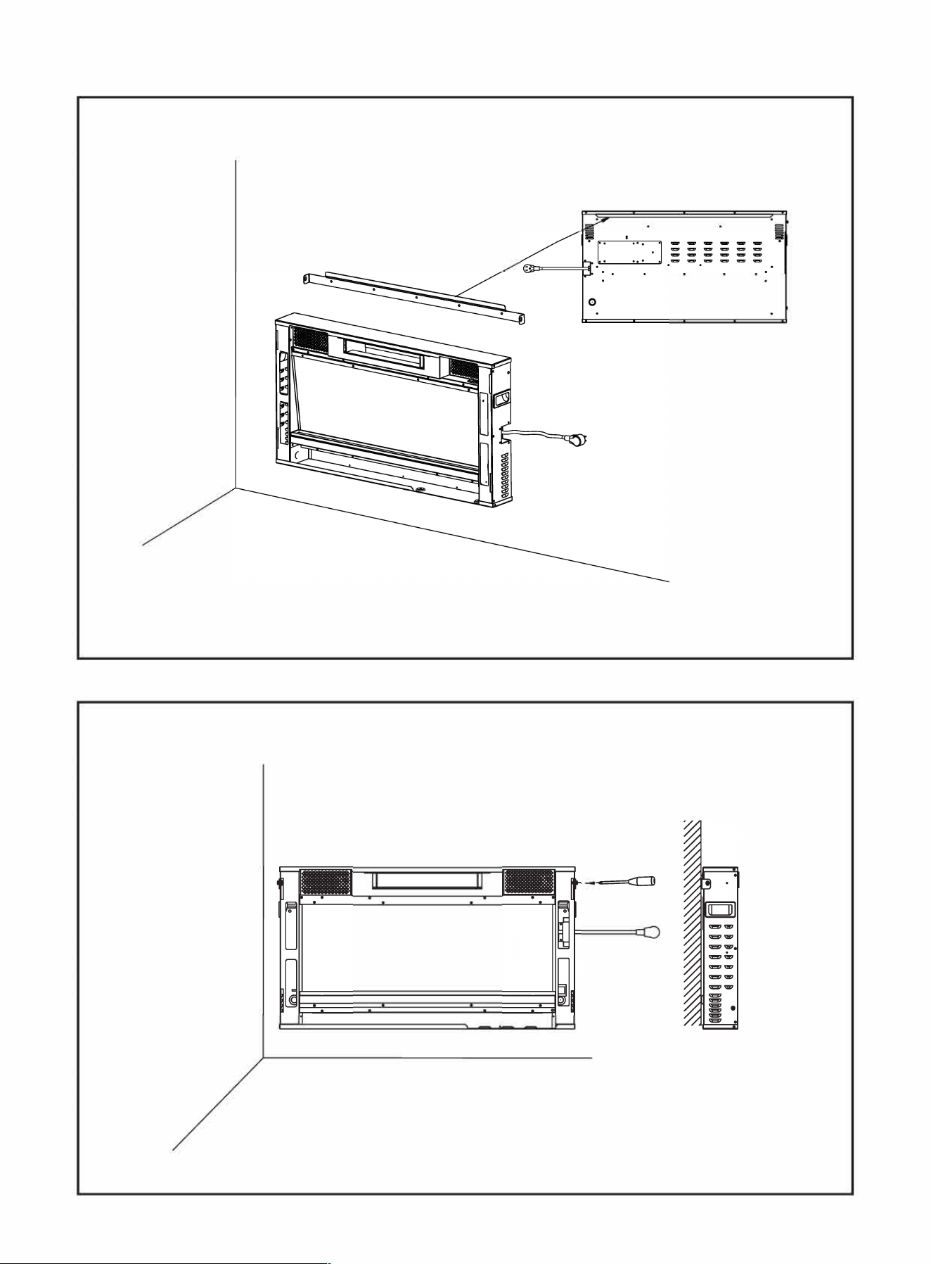
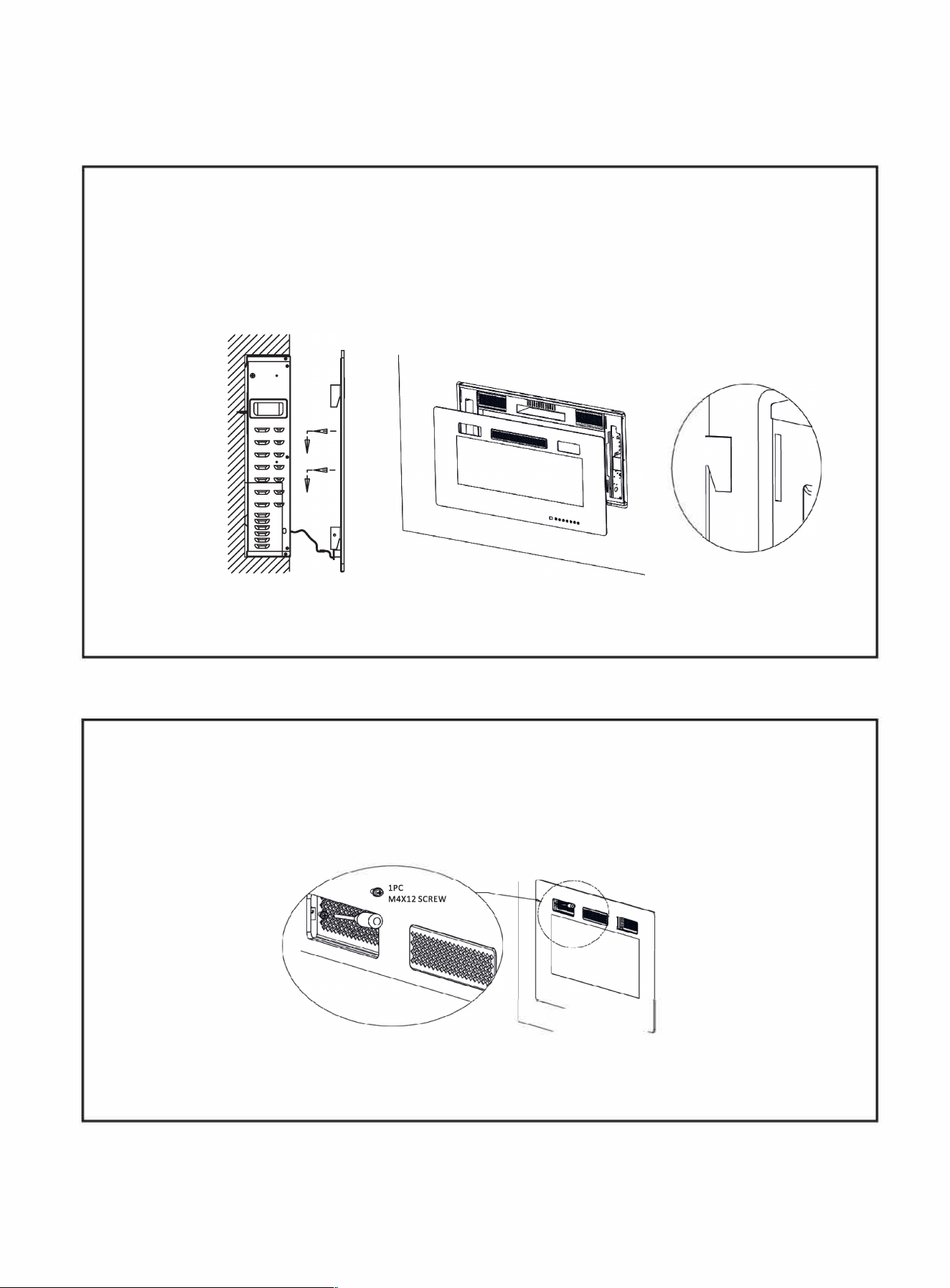
Step 5. Hanging the Fireplace on the Bracket
- Hang the slotting behind the appliance on the hooks at the le and right sides of the bracket.
(Please hold the appliance to avoid dropping down before the installation is finished)
Step 6. Locking the Fireplace on the Bracket
-
M
0
- Lock the bracket at both ends with a screw to ensure a solid combination of the fireplace and bracket
15
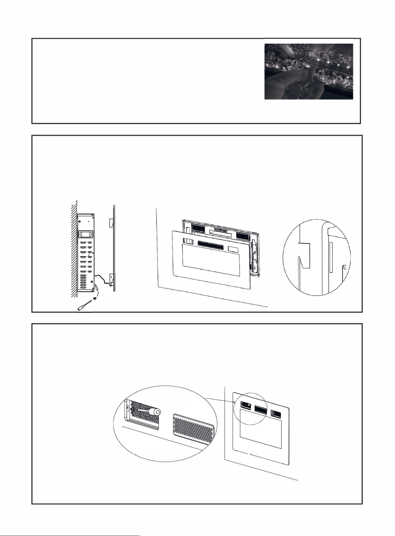
Step 7. Placing the Decorations
- Carefully place crystal (together with the appliance) or other decoration
into the bottom tray on the front of the appliance as illustrated.
NOTE: Media bed kits may have sharp edges, wear safety glasses and
gloves when handling.
Step 8. Hanging the Glass Frame
-Connect the FFC connector before hanging the glass frame on the appliance.
-Gently place the glass panel by aligning the 4 hooks until it snaps into position (sinks down 1-2 cm/0.4-0.8
inches).
-Secure the glass panel with the screw removed in Step 1 (or part B).
-
•
-
•
D
•
•
•
•
•
•
•
Step 9. Refasten the Glass Frame
- Thread the M4X12 screw into the threaded holes on the glass panel. Check the alignment of the glass panel
and securely tighten the screws.
lPC
M4X12 SCREW
0,,
,
,,
,
( Only for all models of style C which has no mesh for the air inlet . )
16
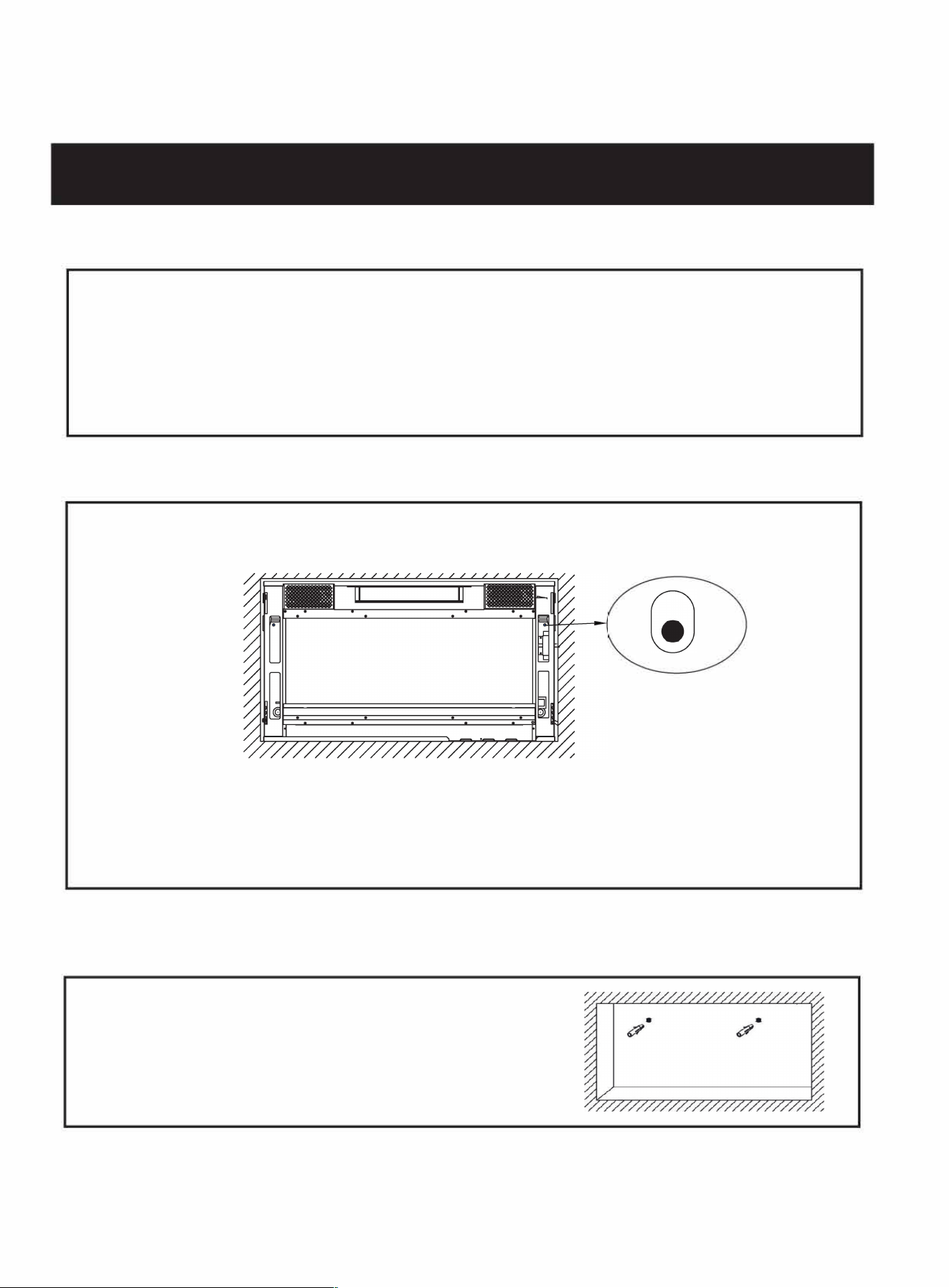
Installation - Built in Construction
Step 1. Removing the Glass Frame
Step 2. Removing the Mounting Bracket
(Step 1 and Step 2 please refer to page 1
3
-14 same as Wall Hanging Installation.)
Step3. Settling the Holes of Screw
- The appropriate cavity (1-2cm bigger for each side) needs to be prepared according to the size of the
appliance.
- Put the fireplace in place, mark the holes which need to be drilled with a pencil. Then take it out of the cavity
again.
Step4. Drilling & Installing the Wall Anchors
- Drill the holes 7 /25 in. (7mm) on the prepared marks.
- Insert the wall anchors (Part B) into the holes using a hammer.
17
Steps. Placing the Pads and Fixing the Fireplace
-
==
=
= =
·
==
==
==
==
- Screws (Part A)
pass through the holes from the front of the fireplace with screwdriver.
(Note: Install carefully and don't let the screws fall into the fireplace.)
- Put the fireplace into the prepared cavity.
- Fasten the fireplace firmly into the wall by the screws for each side.
Step 6. Placing the Decorations
- Carefully place crystal (together with the appliance) or other decoration
into the bottom tray on the front of the appliance as illustrated.
NOTE: Media bed kits may have sharp edges.
W
ear safety glasses and
gloves when handling.
18
Step 7. Hanging the Glass Frame
-Connect the FFC connector before attaching the glass frame on the appliance.
-Gently engage the glass panel by aligning the 4 hooks until the hooks snap into the corresponding positions
(sinks down 1-2 cm/0.4-0.8 inches).
-Secure the glass panel with the screw removed in Step 1 (or part B).
WARNING: It's better to reserve some space between the frame and the wall to enable better air
circulation if available.
Steps. Refasten the Glass Frame
- Thread the M4X12 screw into the threaded holes on the glass panel. Check the alignment of the glass panel
and securely tighten the screws.
�
19
4.0 FINISHING
GRILLE MAY BE HOT, DO NOT TOUCH AIR OUTLET UNTIL COOLED.
THE DOOR HOOKS ARE PART OF A SAFETY SYSTEM AND MUST BE PROPERLY ENGAGED. DO NOT
OPERATE THE APPLIANCE WITH HOOKS DISENGAGED.
FACING AND/OR FINISHING MATERIALS MUST NOT INTERFERE WITH AIR FLOW THROUGH AIR OPENINGS,
OPERATION OF OR DOORS OR ACCESS FOR SERVICE. OBSERVE ALL CLEARANCES WHEN APPLYING COMBUSTIBLE
MATERIALS.
BEFORE DOOR IS REMOVED TURN THE APPLIANCE OFF AND WAIT UNTIL APPLIANCE IS COOL TO THE TOUCH. DOORS
ARE HEAVY AND FRAGILE SO HANDLE WITH CARE.
NOTE: Glass front must be removed and the appliance must be finished in its final location before the
media bed kits are installed. Media bed kits may have sharp edges.
W
ear safety glasses and gloves when
handling.
5.0 OPERATING INSTRUCTIONS
Once the appliance has been plugged into a grounded electrical outlet, it is ready to operate.
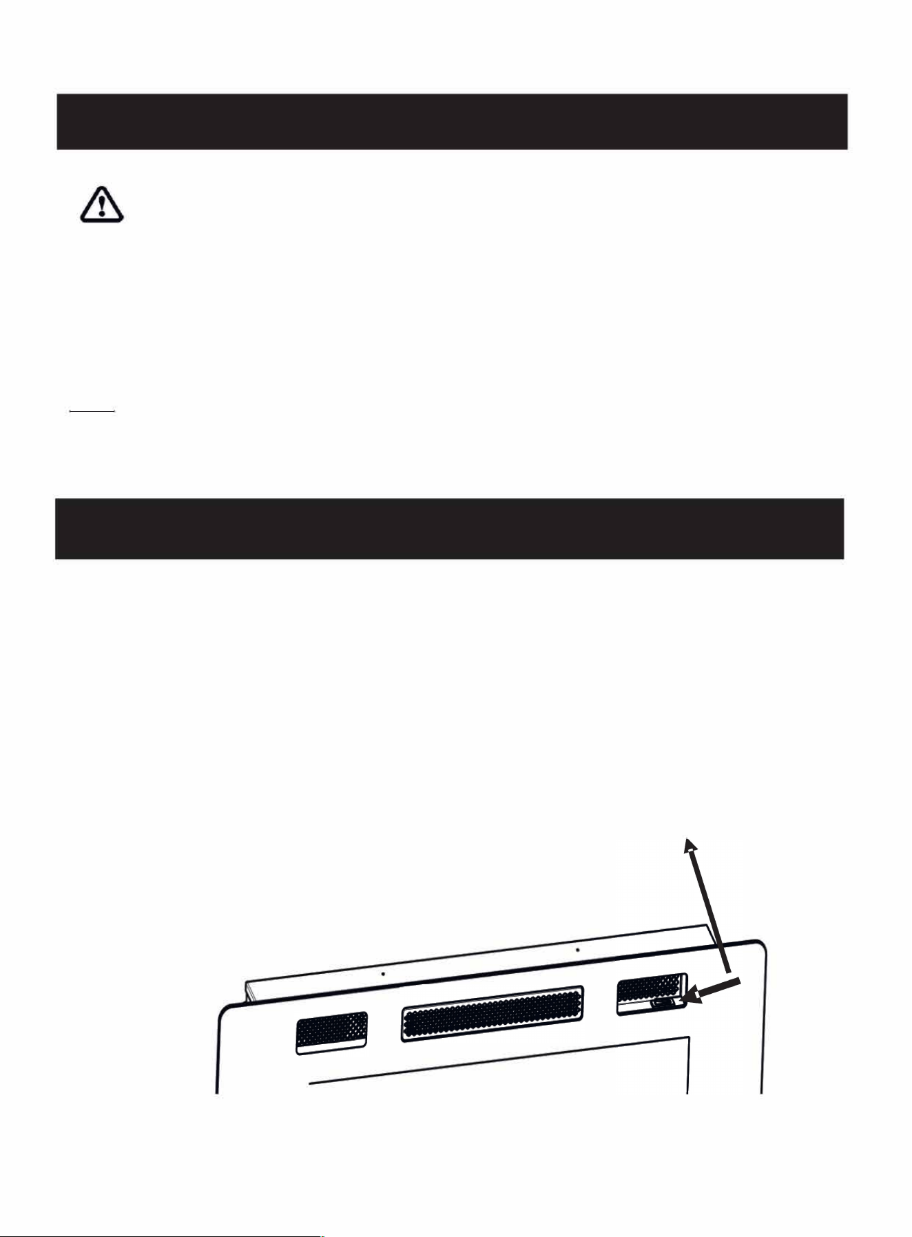
5.1 MAIN POWER BUON
The main power switch for all types is located on the upper right of the fireplace except the style C of model LC
whose main power switch is on the front right.
Press the indicator to turn on the appliance, and press the other side to turn it off.
MAIN POWER BUTTON
Note: Make sure the Main Power Switch is turned on before operating.
20
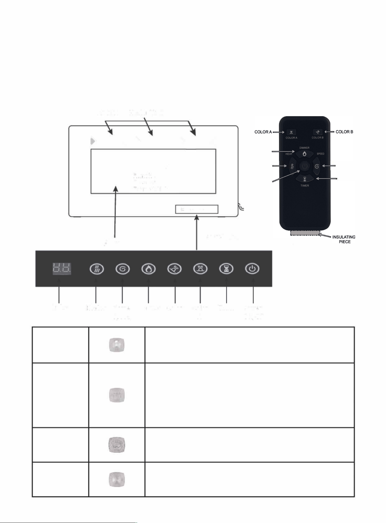
5.2 CONTROL PANEL/ REMOTE CONTROL OPERATION
(Main Power Switch must be turned ON before using the remote control.)
The touch display panel is shown on the bottom right of the front of the appliance.
♦Move the battery's transparent insulating piece away before using the remote control.
Display
POWER
DIMMER
TIMER
FLAME SPEED
Air Inlet Heater Vent
-
Fe
Heater Flame
Sed
�
�
�
- -
0
R/
R
F LC
D •••••••
Control Panel
Dimmer Color
B
Color
A
mer
DIMMER
HEAT
POWER
ON/OFF
wer
ON/OF
FLAME
SPEED
TIMER
REMOTE CONTROL
Turn the appliance ON/OFF.
NOTE: Make sure the main switch on the top of the fireplace is turned
on before operating.
Control Flame brightness.
5
Settings: ( L 1-L2-L3-L4-L5 ) Flame dims from
L1 to L5. L5
is the brightest
setting.
NOTE: Long press the "DIMMER" button for 6 seconds, and the appliance will go
into sleep mode: all the lights are off, but the heating function goes on.
Long-press again (>6 sec.) to restore the appliance to the normal mode.
Control the Timer.
8 Settings: (lh, 2h, 3h, 4h, Sh, 6h, 7h, 8h) Press button until the desired
setting is reached.
Control Flame speed.
5 Settings: (
U1-U2-U3-U4-US)
Flame speed from
U1 to
U5. U5 is the fastest
setting.
21
HEATER
�
COLORA
�
�
COLOR B
Control the Heater.
Press the button to initiate the heater.
(OFF) no heater or blower.
( - ), heater blows warm air(750W)
( -- ), heater blows hot air(lS00W)
NOTE: Heater functions cycle from (OFF) ( - )( -- )
Control the flame color.
12 Settings: 1.red 2.yellow 3.blue 4.orange 5.red & yellow 6.red &
blue7.red & orange 8.yellow & blue 9. yellow & orange 10.blue & orange
11.red & yellow & blue 12.multicolor
NOTE: When you press the button for 6 seconds, the indicator will show digital "O",
and the flame color and brightness will be changed automatically.
Control the flame bed color.
12 Settings: 1.red 2.gentian blue 3.green 4.pink 5.yellow 6.cyan 7.purple
8.white 9.saffron 10.sky blue 11.verdant 12.capri blue
NOTE: When you press the button for 6 seconds, the indicator will show
digital "O", and the flame color and brightness will change automatically.
WARNING: Do not move or remove the mesh trim panel, when the appliance is plugged in and operating. This
will cause the remote control and touch panel to no longer function.
NOTICE: When the heater is turned on for the first time, a slight odor may be present. This is normal and should not occur
again unless the heater is not used for a long period of time.
NOTICE: To improve the heater's performance, aim the remote control at the front of the fireplace. DO NOT press the buttons
too quickly. Give the unit enough time to respond to each command.
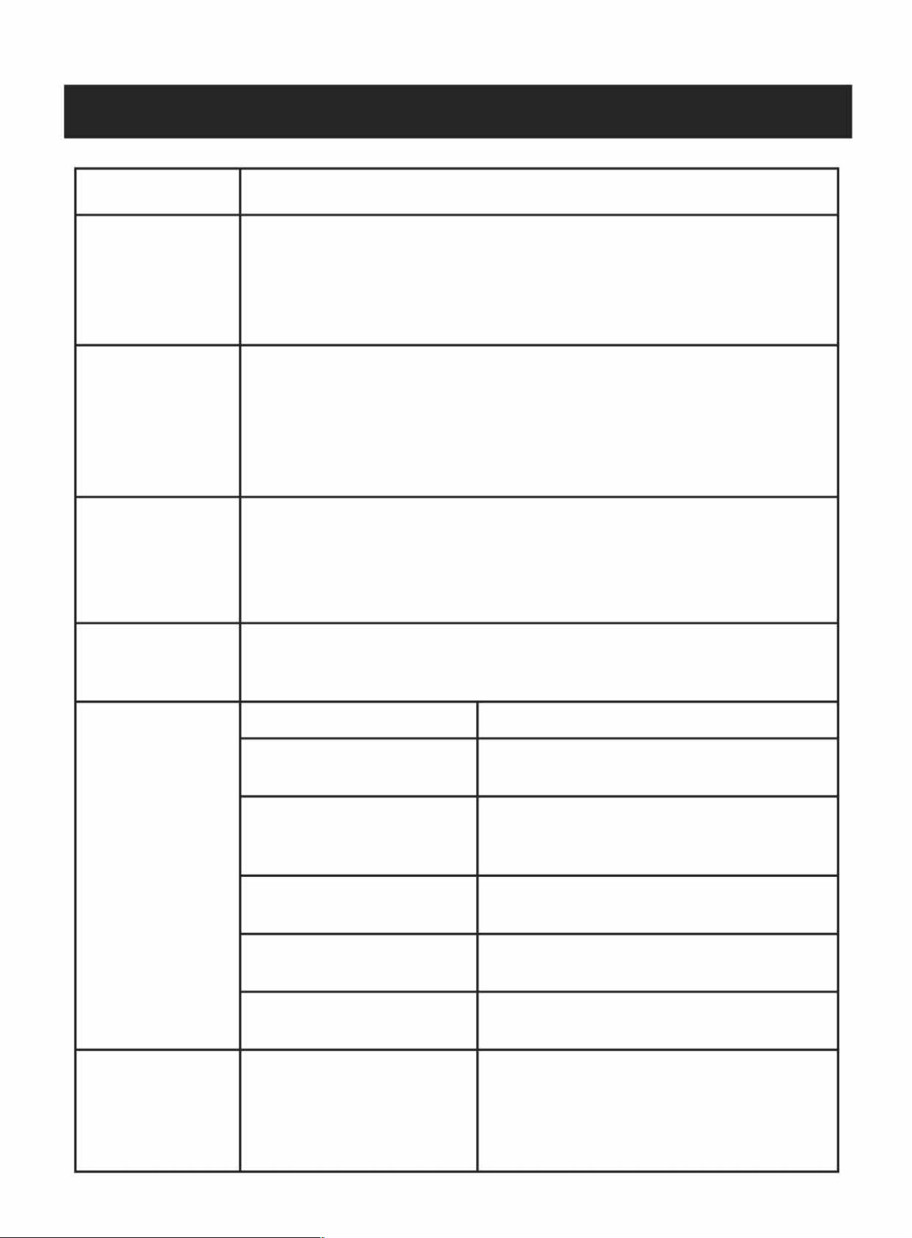
5.3 REMOTE CONTROL
♦ Move the battery's transparent insulating piece away before using.
Remote
(REAR VIEW)
Bae Holder ----
22
Batte must be recycled or
disposed of properly. Check with
your Local Authority or Retailer
for recycling advice in your area.
6.0 TROUBLE SHOOTING GUIDE
PROBLEM
SOLUTION
The mounting bracket
cannot be removed
1.The mounting bracket i
s
pre-attached. Unscrew the two screws a
t both sides of the
fireplace with a Phillips screwdriver, and then remove the pre-attached mounting
bracket.
2.lf the problem is still not solved, please contact us via Amazon Message or call
customer service number:213-4467172 or 661-4358826.
1.Make sure the Power Switch on the control panel is turned on before operation.
2.Make sure you have reconnected the data cable which was pulled out when you
removed the glass frame.
3.lf the problem is still not solved, please contact us via Amazon Message or call
customer service number:213-4467172 or 661-4358826.
1.Don't cover the air outlet.
2.Unplug the unit, and wait for 10 minutes and try to open it again.
3.lf the problem is still not solved, please contact us via Amazon Message or call
The control panel
functions do not
work.
Sudden power outage
during the heating
process
The appliance does
not blow hot air when
it turns on and off.
customer service number:213-4467172 or 661-4358826.
This is normal. The fans blow cool air while the appliance gradually heats up. The fans
blow aer the appliance turns off to cool and prevent overheating.
1. Main Power supply switch is o. Turn the main power supply switch to "ON" position.
Heater doesn't turn on
with the power
switch.
Too many appliances are on this circuit. Make sure that
the electrical supply for this unit is an independent circuit.
Make sure the power cord is plugged into a
functioning and properly grounded 15 Amp 1
2
0V AC
electrical outlet.
Contact a qualified electrician to replace the power
Check the power outlet and replace it with a new one.
Contact a qualified electrician to check all wiring for
loose connections.
2
.
Circuit breaker has been
tripped.
3. Heater is unplugged from the wall outlet.
4. Power cord or power plug are
damaged.
5. Power outlet for power plug
prong is loose.
6. Loose wiring.
1. Heater switches is on, but Flame
is not on.
Heater is on, but no
flame or low flame
intensity.
Long-press the "DIMMER" button for 6 seconds, the
appliance will go into sleep mode. All the lights o,
the heating function goes on. Long-press for 6
seconds again, the appliance will back to normal
mode.
23
cut off.
The remote control
does not work.
There is a
n odor
coming from the
heater.
1. The battery is not properly
installed.
2. Not pointing to the right
position.
3. There is an obstacle in front
of the machine.
4. Press the remote control
buttons too quickly.
Make sure the battery is properly installed. Move the
battery's transparent insulating piece away before
using.
Aim the remote control at the receiver.
Remove the obstacles. Items between the remote
control and the remote-control receiver will block
the signal.
Don't press the remote-control buttons too quickly. Give
the unit enough time to respond to your commands.
The heater may emit a slight, harmless odor when first used. This is a normal condition
caused by the initial heating of the internal parts and will not occur again.
NOTE: For the most of functional problems, you can unplug the unit
,
wait for 10 minutes and plug it again, the machine will reset to the
initial status (original system state).
If the problem is still not solved, feel free to contact us via Amazon
M
essage or
customer service number: 213-4467172 or 661-4358826
7.0 MAINTENANCE
DISCONNECT POWER AND ALLOW HEATER TO COOL BEFORE ATTEMPTING ANY MAINTENANCE OR
� CLEANING TO REDUCE THE RISK OF FIRE, ELECTRIC SHOCK OR DAMAGE TO PERSON.
THE FIREPLACE SHOULD NOT BE OPERATED WITH AN ACCUMULATION OF DUST OR DIRT ON OR IN THE UNIT, AS THIS
CAN CAUSE A BUILD UP OF HEAT AND SUBSEQUENT EVENTUAL DAMAGE. FOR THIS REASON THE HEATER MUST BE
INSPECTED REGULARLY, DEPENDING ON CONDITIONS AND AT LEAST AT YEARLY INTERVALS.
7.1 PARTIALLY REFLECTIVE GLASS CLEANING
The partially reflective glass is cleaned in the factory during the assembly operation. During shipment, installation,
handling, etc., the partially reflective glass may collect dust particles; these can be removed by dusting lightly with a
clean dry cloth.
To remove fingerprints or other marks, the partially reflective glass can be cleaned with a damp cloth. The partially
reflective glass should be completely dried with a lint-free cloth to prevent water spots. To prevent scratching, do
not use abrasive cleaners.
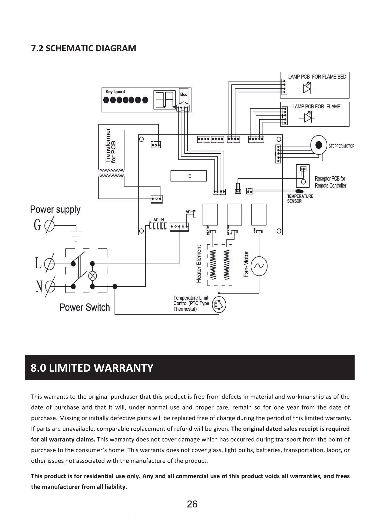
25