

2
Table of Contents
Usage Notices
5 Precautions for Repair
6 ESD (Electrostatic Discharge) Precautions
7 Instructional Icons
Software Update
8 Updating Software through FOTA
8 Software Update Failure
8 Updating Software through Smart Switch
9 Recovering from a Software Update Failure
9 Recovering on Another Computer
10 Performing a Factory Data Reset
Quality Test
12 Quality Test Using the Samsung Members App
12 Device Diagnostics
13 Test Items
Calibrations
26 Calibrations
26 Used Parts and Calibration Functions in Supported Models
27 Using the Self Repair Assistant App
32 Optical Fingerprint Sensor Calibration
35 Resetting the Battery Cycle Count
38
Range Sensor Calibration
40 Touch Screen Panel Calibration
42 Speaker Calibration

3
Table of Contents
44 Under-display Camera Calibration (Fold Models Only)
46 Digital Hall Sensor Calibration (Fold and Flip Models Only)
Exploded View and Parts List
49 Exploded View
50 Parts List
Disassembly and Assembly
52 Tools for Disassembly and Assembly
55
Fasteners (Adhesives and Materials) for Assembly
60 Disassembly and Reassembly for replacement
61 SIM Card Tray
61
Disassembly
63
Reassembly
64
Screen
64
Disassembly
76 Reassembly
94 Bracket
94 Disassembly
96
Reassembly
98
Microphone
98
Disassembly
100
Reassembly
104
Charging Port
104 Disassembly
113 Reassembly
123
Rear Camera
123
Disassembly
126
Reassembly

4
Table of Contents
129 Front Camera
129 Disassembly
131 Reassembly
133 Speaker 1
133 Disassembly
144 Reassembly
157 Speaker 2
157 Disassembly
166 Reassembly
175 Speaker 3
175 Disassembly
187 Reassembly
202 Speaker 4
202 Disassembly
211 Reassembly
223 Battery
223 Disassembly
228 Reassembly
236 Button
236 Disassembly
238 Reassembly
240 Back Cover
240 Disassembly
266 Reassembly

Usage Notices
5
Usage Notices
All functionality, features, specifications, and other device information provided in
this document, including but not limited to, benefits, design, pricing, components,
performance, availability, and capabilities of the device are subject to change without
notice. Samsung reserves the right to alter this document or the device described herein
at any time, without obligation to provide notification of such changes.
Precautions for Repair
Samsung is not liable for any damage or defect determined to be caused by repair by
a non-authorised carrier, self repair or non-professional repair of the device. Samsung
is not liable for any resulting damage to the device, or any injury or other device safety
issue caused by any attempt to repair the device which does not follow these repair and
maintenance instructions.
Any damage to the device or defect caused by an attempt to repair the device by any
person other than a Samsung certified carrier will not be covered by the warranty.
•
Use only demagnetised tools that are specifically designed for small electronic
repairs, as most electronic parts are sensitive to electromagnetic forces.
•
Use only high quality screwdrivers when servicing devices. Low quality screwdrivers
can easily damage the heads of screws.
•
Always use genuine replacement parts. Third-party replacement parts may not
function properly and could cause a fire or injury.
•
Some parts, such as sensors (laser AF/proximity/fingerprint), the rear camera,
the TSP (touch panel), speakers, and other components, may need calibration to
guarantee their performance after repair.
•
The performance of the device’s water and dust resistance cannot be guaranteed
when it is repaired by the user or another unskilled worker.
•
If you need to access the failure data of your device or need to get a more detailed
diagnosis, visit a Samsung Service Centre.
•
If you need to replace unsold parts, visit a Samsung Service Centre and receive
further instruction.
•
Before conducting repairs, remember to make backup copies of all important data
stored in the device.

Usage Notices
6
•
Make sure to wear the appropriate safety equipment before carrying out repairs.
Samsung is not responsible for injuries that may occur because of not wearing the
proper safety equipment. Refer to Tools for Disassembly and Assembly for a list of
tools that you will need for assembling and disassembling the device.
•
Repair the device in a safe place.
•
Before repairing the device, make sure the device is turned off. To turn off the
device, press the Volume Down button and the Side button at the same time, or open
the notification panel and tap the Power icon.
•
If the device is damaged, emits smoke, or if you smell something burning, stop using
the device immediately and contact Samsung.
•
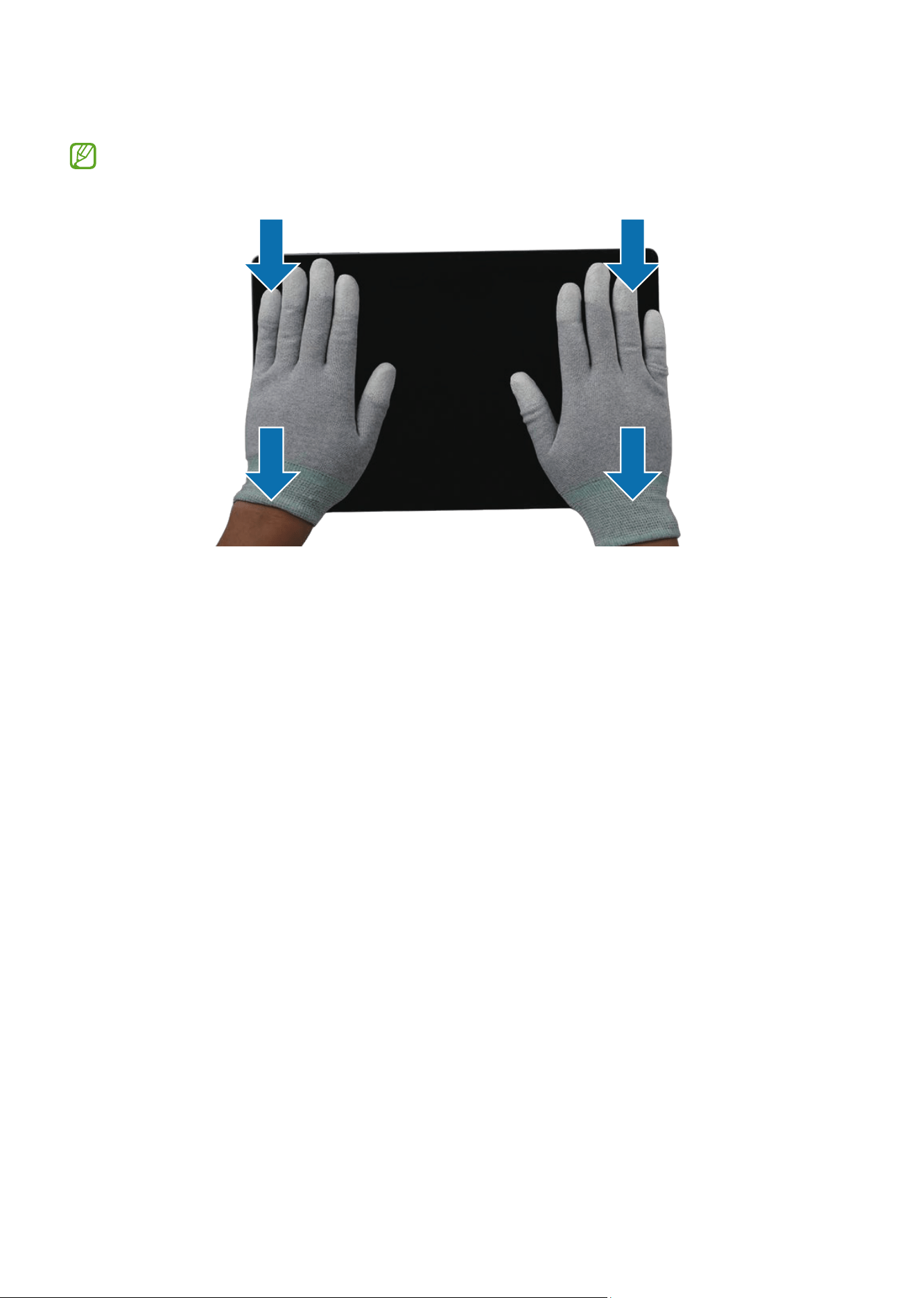
It is recommended to use safety equipment such as glasses, gloves, and a mask
when repairing the device.
•
Be careful not to damage the device when removing the back cover.
•
Before assembly, ensure that there are no screws or foreign objects around the
battery.
•
During assembly, check if there are any abnormalities before reattaching the back
cover, and be careful not to damage the battery by hitting or denting it. If the battery
is damaged, visit a Samsung Service Centre.
•
Do not place the device directly into a microwave and heat it.
•
Before repairing your device, make sure its battery is fully discharged.
•
Visit www.samsung.com to view the device information, related material, and safety
information.
ESD (Electrostatic Discharge) Precautions
It is the sudden flow of electricity between two electrically charged objects caused by
contact, an electrical short, or dielectric breakdown. ESD can cause negative effects on
mobile devices, especially electrical parts.
•
It is recommended to use ESD safety (Anti-static) equipment such as an anti-static
wrist strap and gloves, and an ESD safe mat when repairing the device.
•
Increase the airflow to the work area to decrease the chance of accidental static
electricity discharges, as the potential for static electricity discharge may be
increased in low-humidity environments, such as air-conditioned rooms.

Usage Notices
7
Instructional Icons
Warning: situations that could cause injury to yourself or others
Caution: situations that could cause damage to your device or other equipment
Notice: notes, usage tips, or additional information

Software Update
8
Software Update
Updating Software through FOTA
Update your device’s software through the firmware over-the-air (FOTA) service. You can
also schedule software updates.
Launch the
Settings
app and tap
Software update
→
Download and install
.
•
Install now
: Install updates.
•
Schedule install
: Set the time to install updates automatically.
•
You may incur additional charges when updating the software through a mobile
network.
•
If the latest software has been downloaded to the device, these options will not
appear.
Software Update Failure
If your device becomes disconnected from a network before the update is complete, the
update may fail. Reconnect to a network and complete the update.
Updating Software through Smart Switch
You can use Smart Switch to update your device’s software to the latest
version. You must download the desktop version of the Smart Switch app from
www.samsung.com/smartswitch.
•
This feature may not be supported on some devices or computers.
•
Limitations apply. Visit www.samsung.com/smartswitch for details. Samsung
takes copyright seriously.
1 On the computer, visit www.samsung.com/smartswitch to download Smart Switch.
2 On the computer, launch
Smart Switch
.
3 Connect your device to the computer using the device’s USB cable.
4 Click
Update
.

Software Update
9
5 Read the on-screen instructions and click
Continue
.
6 Read the precautions about the update and click
OK
.
7 Read and agree to the terms and conditions.
The update will start.
Recovering from a Software Update Failure
If a software update is interrupted because of an error on your device or computer, your
device may fail to operate normally. If this occurs, you can perform a factory data reset
on your device for emergency recovery.
Before performing the factory data reset, remember to make backup copies of all
important data stored in the device. Samsung is not responsible for the loss of data
stored in the device.
1 Disconnect your device from the computer and launch
Smart Switch
again on the
computer.
2 Click
→
Emergency Software Recovery and Reset
.
The device list will appear.
3 Click the device that experienced a software update error and click
Device reset
→
OK
.
The device will perform a factory data reset.
Recovering on Another Computer
If the emergency recovery process continues to fail on the computer where the software
update failed, you can repair your device on another computer using the recovery code.
This will include a factory data reset of your device.
•
Before performing the factory data reset, remember to make backup copies of
all important data stored in the device. Samsung is not responsible for the loss
of data stored in the device.
•
The recovery code can be found only on the computer where the software
update has failed.
1 On the computer where the software update has failed, launch
Smart Switch
.
2 Click
→
Emergency Software Recovery and Reset
.
Software Update
10
3 On the devices list, click the device that failed to update the software and check the
recovery code.
4 On another computer, launch
Smart Switch
.
5 Click
→
Emergency Software Recovery and Reset
→
Emergency code recovery
.
6 Enter the recovery code and click
OK
.
7 Follow the on-screen instructions to put your device into recovery mode and
complete the emergency recovery.
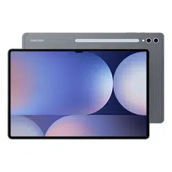
Performing a Factory Data Reset
The factory data reset restores the device’s default settings. This erases all data,
including files and downloaded apps, from the device.
Before performing the factory data reset, remember to make backup copies of all
important data stored in the device. Samsung is not responsible for the loss of data
stored in the device.
Make sure your device’s battery level is sufficient, as losing power during a factory
reset may result in system problems.
1 Launch the
Settings
app and tap
General management
→
Reset
→
Factory data
reset
.
2 Read the on-screen instructions and check
which account you are signed in with.
If your device is signed in to your Google
account, log out of your Google account. If
you do not log out of your Google account,
logging in to another account after the
factory data reset will not be possible,
because your device will be locked.

Software Update
11
3 Tap
Reset
→
Delete all
.
All data will be deleted when rebooting.
During a factory data reset, the device may repeat rebooting and the logo may be
displayed for a long time.
Quality Test
12
Quality Test
Quality Test Using the Samsung Members App
It is recommended to evaluate your device through the Samsung Members app
after it has been repaired to guarantee its performance. If the test results show any
abnormalities or that another malfunction has occurred because of the repair, visit a
Samsung Service Centre to receive further instruction. Any malfunctions caused by your
repair may incur additional repair charges.
•
The Samsung Members app is subject to update without any prior notice.
•
To use this feature, you must sign in to your Samsung account.
•
Some features may not be available depending on the carrier or model.
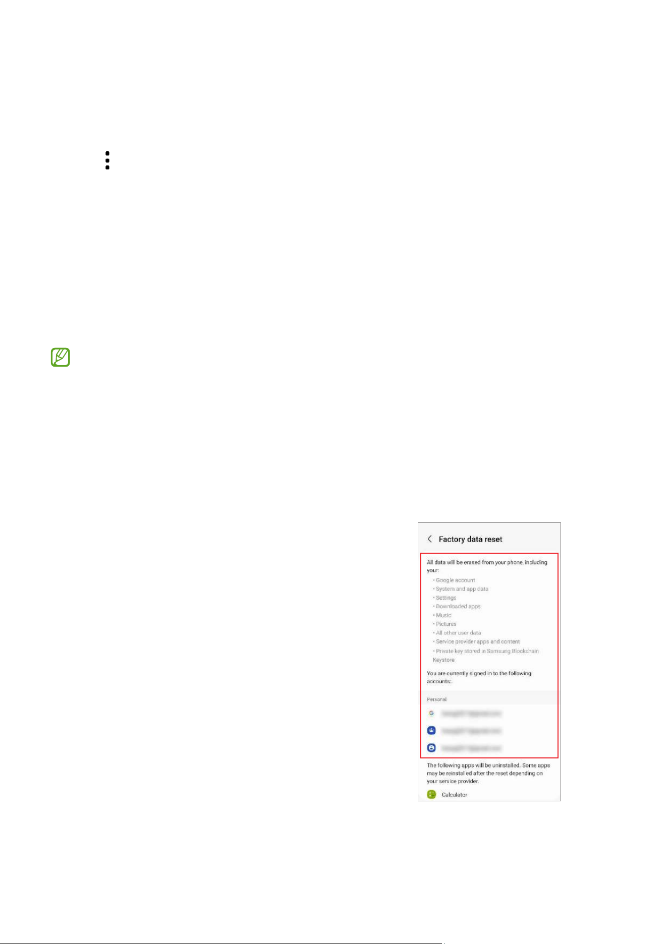
Device Diagnostics
1 Launch the
Samsung Members
app.
If you do not have the app, download it from the
Galaxy Store
or
Play Store
.
2 Tap
Support
→
Phone diagnostics
.
The diagnostics screen will appear and you can
check the test status and items.
Quality Test
13
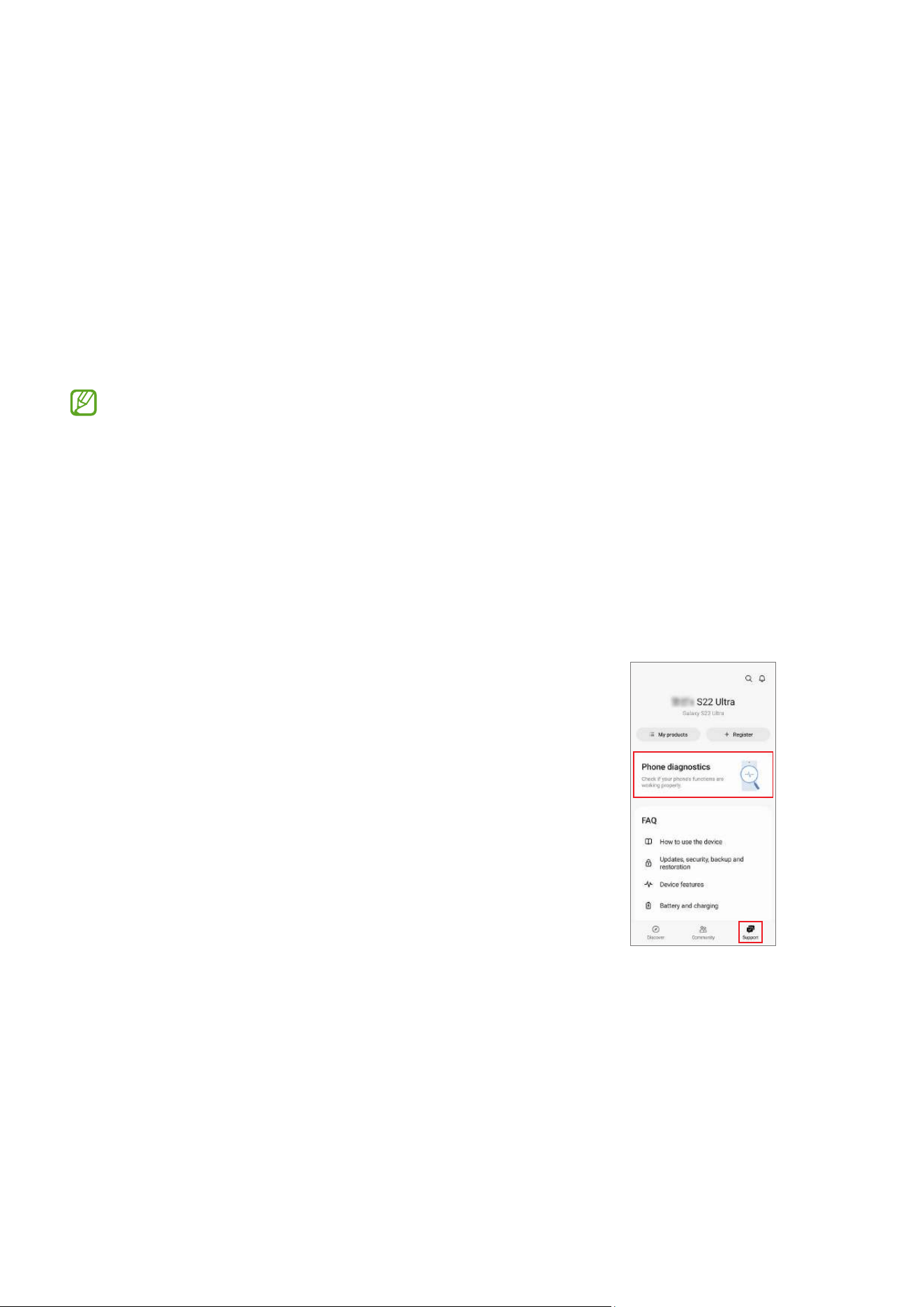
3 Tap
Test all
.
The device performs a test on all items.
When the test is finished, you can check the test
results.
•
Tick mark: Working normally
•
Exclamation mark: Needs further inspection
•
The test proceeds automatically, but you may
need to follow the on-screen instructions
depending on the test item. Keep an eye on
the screen during testing to ensure smooth
progress.
•
If the exclamation mark appears on any test
items after finishing the test, tap them to find
the solutions. If the problem persists, visit a
Samsung Service Centre.
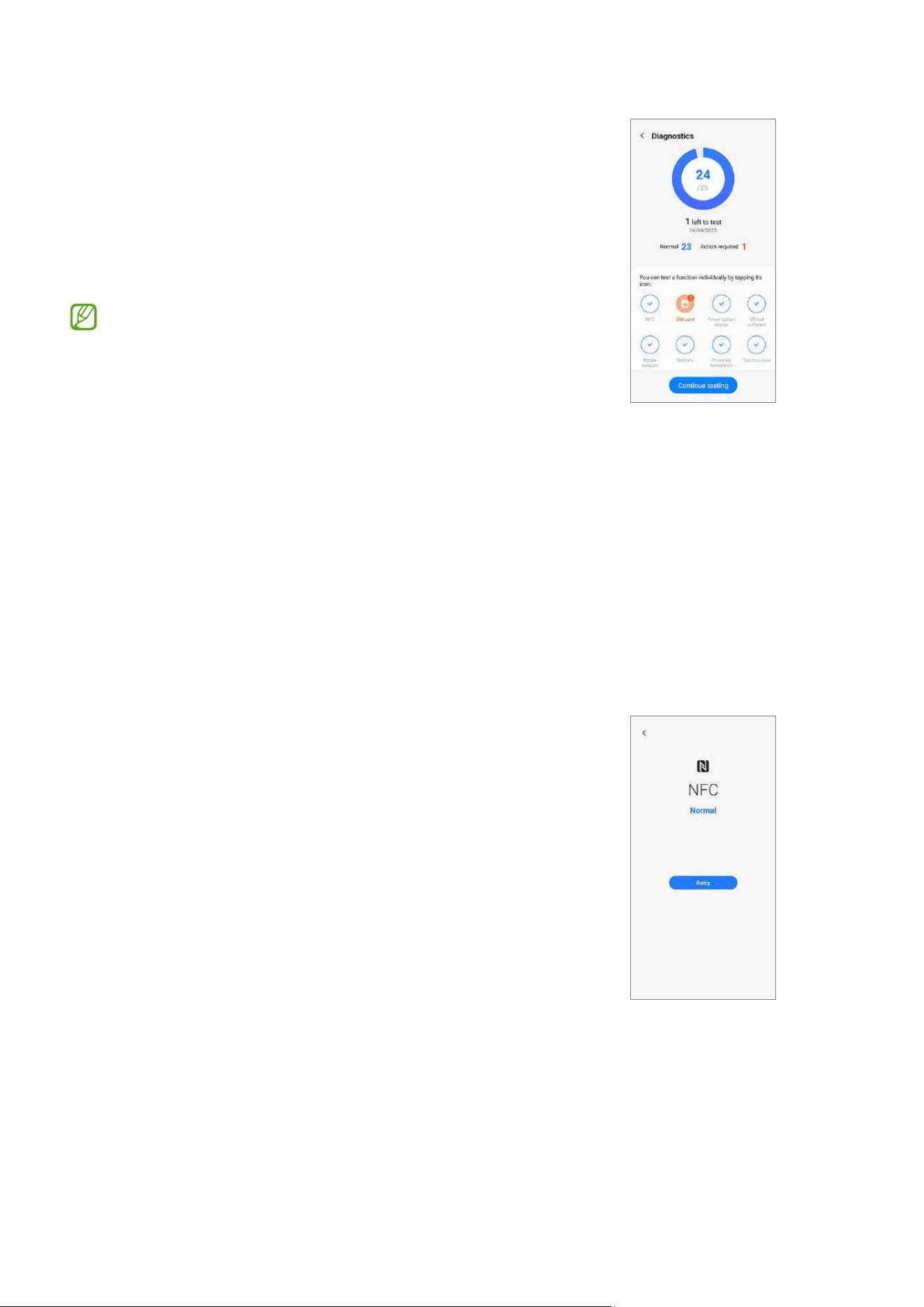
Test Items
NFC
•
Function: Check whether your device can read
near field communication (NFC) tags that contain
information about products.
•
Provided information
‒
Status: View whether the feature is working
normally.
Quality Test
14
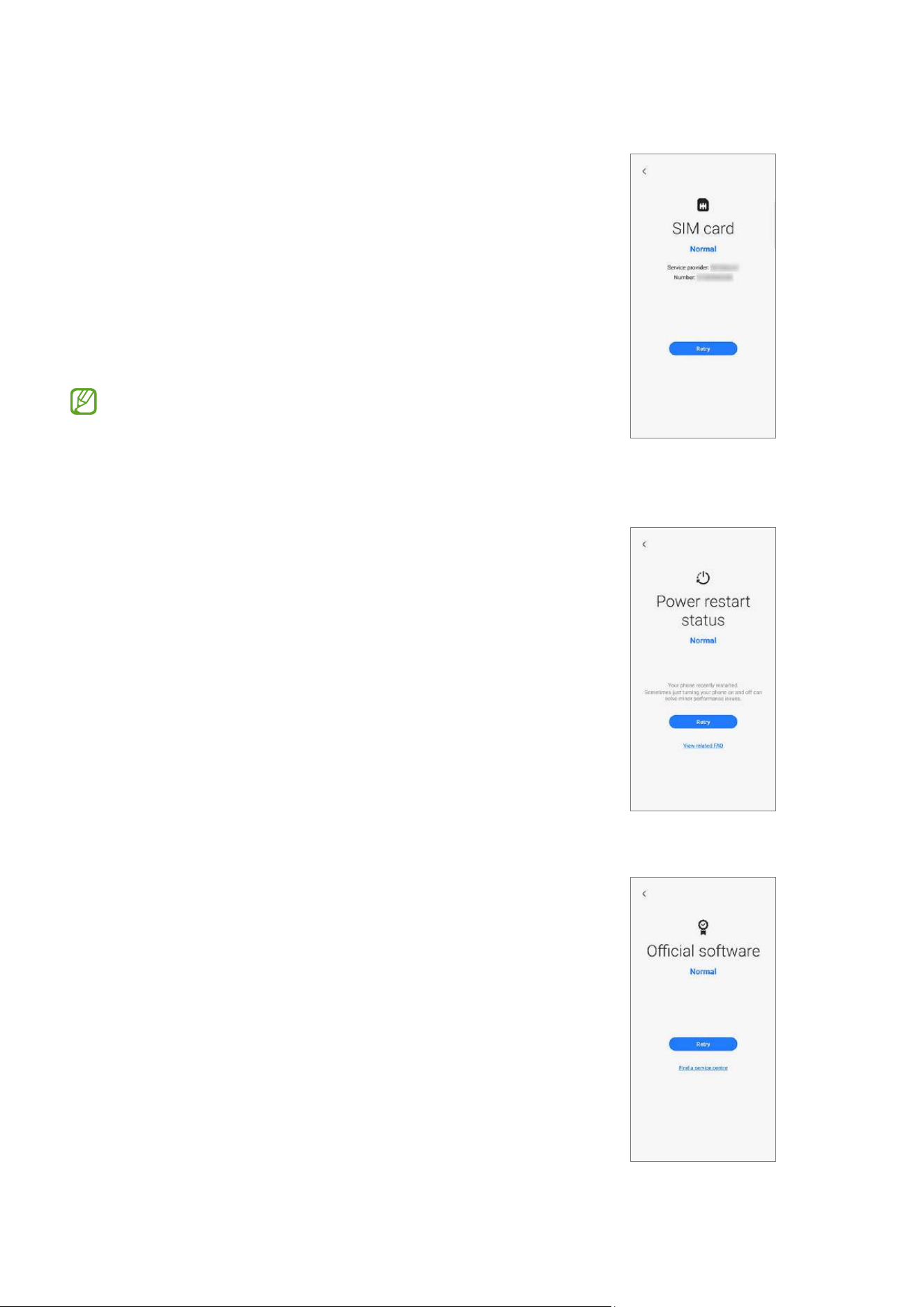
SIM card
•
Function: Check whether the SIM card is working
normally.
•
Provided information
‒
Status: View whether the feature is working
normally.
‒
Service provider: View the carrier.
‒
Number: View the phone number.
If the test result is not
Normal
, remove the SIM
card from the SIM card tray and replace it. If
possible, try again with another SIM card.
Power restart status
•
Function: Check your device’s restart history.
•
Provided information
‒
Status: View whether the feature is working
normally.
‒
FAQ: View frequently asked questions.
‒
History: View your device’s restart history.
Official software
•
Function: Check whether the software is working
normally.
•
Provided information
‒
Status: View whether the feature is working
normally.
‒
Service information: View the Samsung
Service Centre location.
Quality Test
15
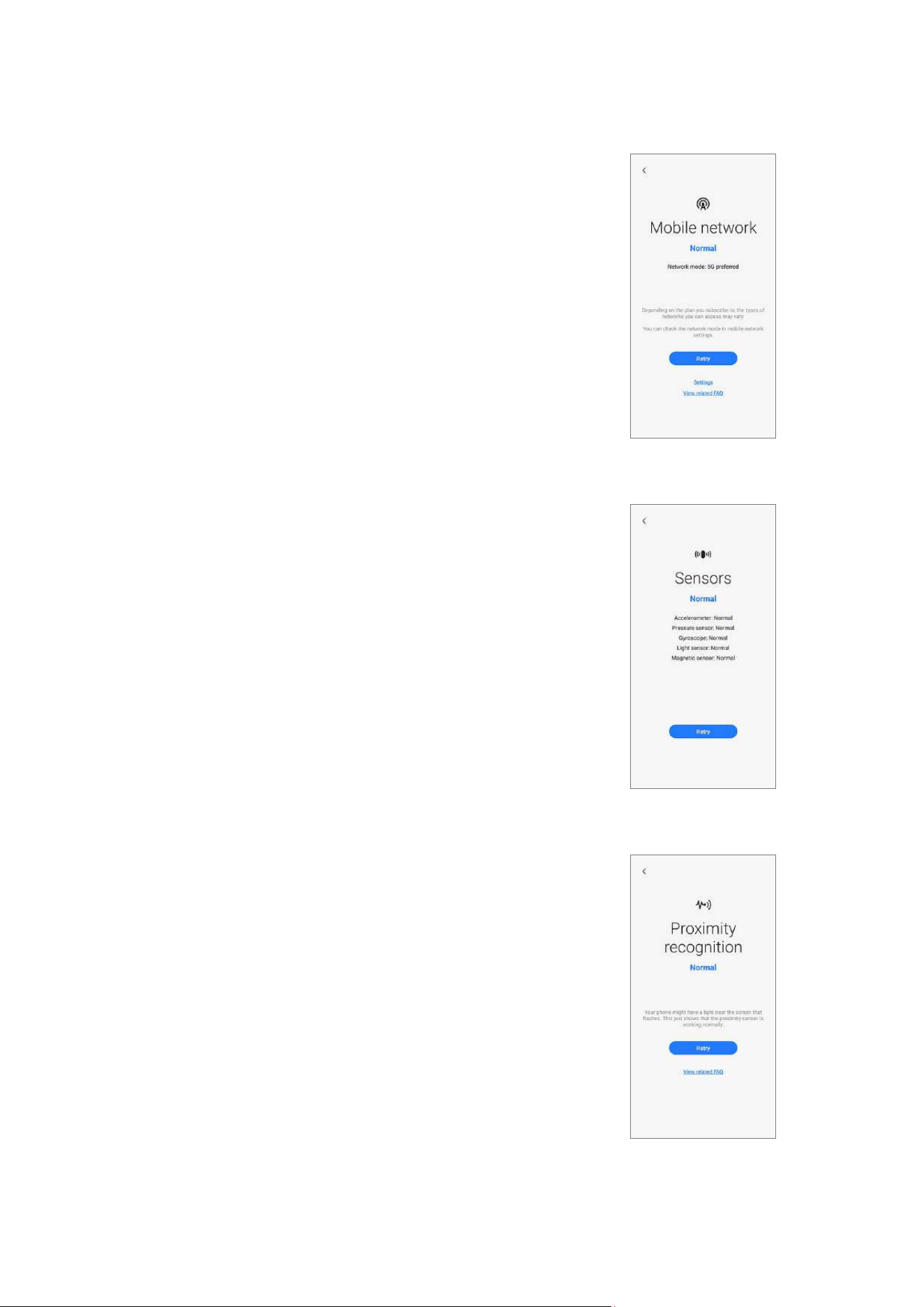
Mobile network
•
Function: Check whether your mobile network is
working normally.
•
Provided information
‒
Status: View whether the feature is working
normally.
‒
Settings: Configure your mobile network
settings.
‒
FAQ: View frequently asked questions.
Sensors
•
Function: Check whether the sensors are working
normally.
•
Provided information
‒
Status: View whether the feature is working
normally.
‒
Sensor types: View the status of each sensor.
Proximity recognition
•
Function: Check whether the proximity
recognition feature is working normally.
•
Provided information
‒
Status: View whether the feature is working
normally.
‒
FAQ: View frequently asked questions.
Quality Test
16
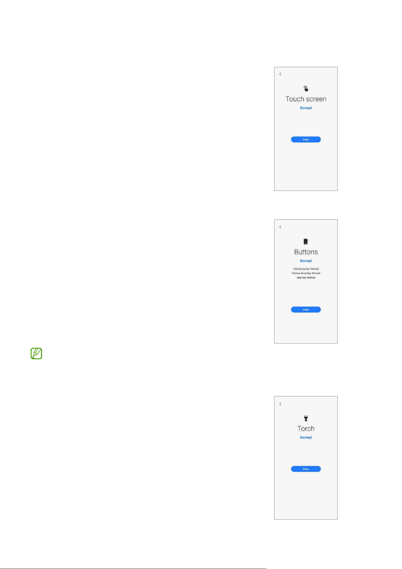
Touch screen
•
Function: Check whether the touchscreen is
working normally.
•
Provided information
‒
Status: View whether the feature is working
normally.
Buttons
•
Function: Check whether the buttons are working
normally.
•
How to check:
Press the buttons by following the directions on
the screen.
•
Provided information
‒
Status: View whether the feature is working
normally.
‒
Button types: View the status of each button.
Make sure that the buttons are not
contaminated to get more accurate test results.
Torch
•
Function: Check whether the torch is working
normally.
•
Provided information
‒
Status: View whether the feature is working
normally.
Quality Test
17
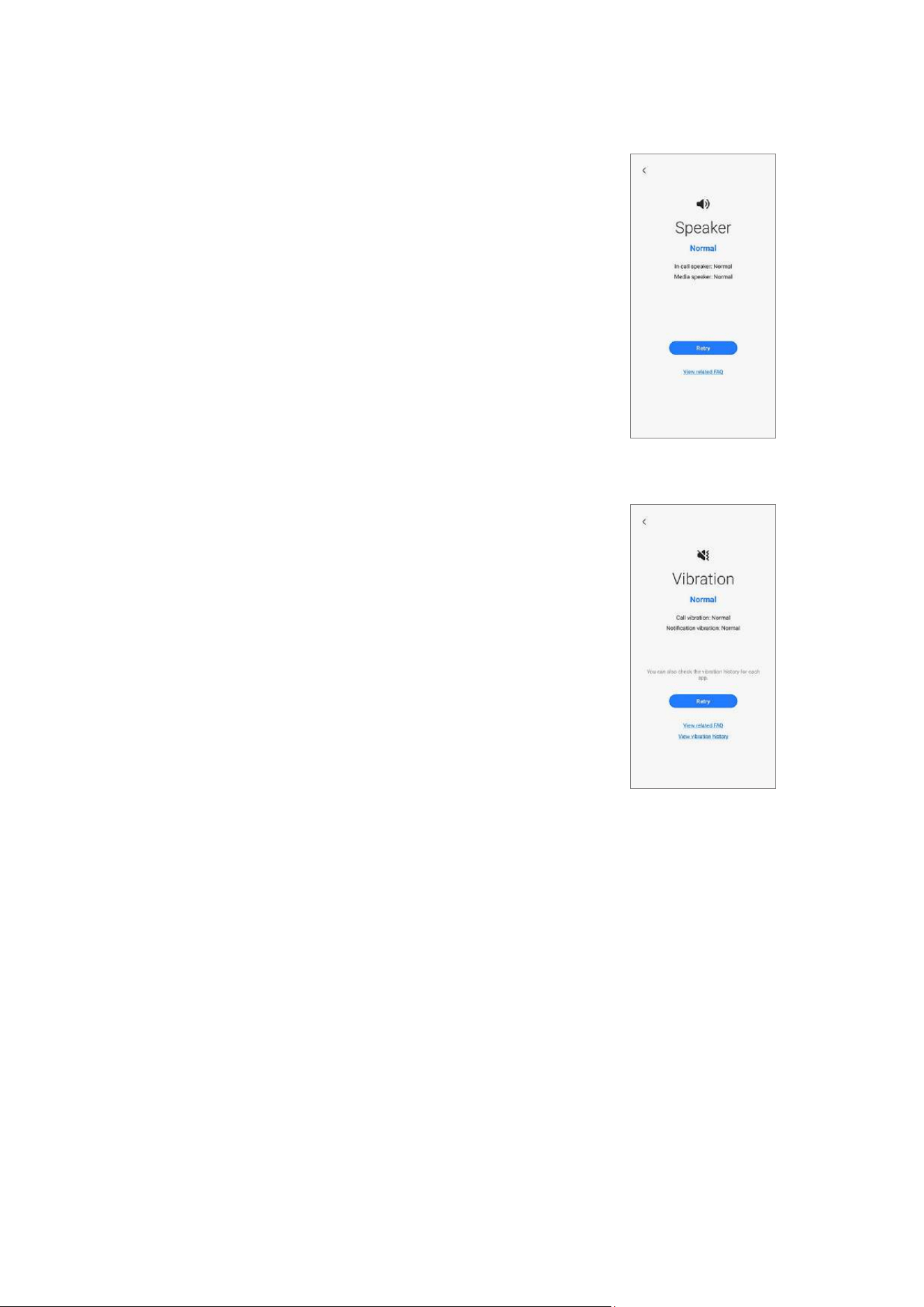
Speaker
•
Function: Check whether the speakers are
working normally.
•
Provided information
‒
Status: View whether the feature is working
normally.
‒
Speaker types: View the status of each
speaker.
‒
FAQ: View frequently asked questions.
Vibration
•
Function: Check whether the vibration feature is
working normally.
•
Provided information
‒
Status: View whether the feature is working
normally.
‒
Vibration types: View the status of each type
of vibration.
‒
FAQ: View frequently asked questions.
‒
History: View the vibration history.
Quality Test
18
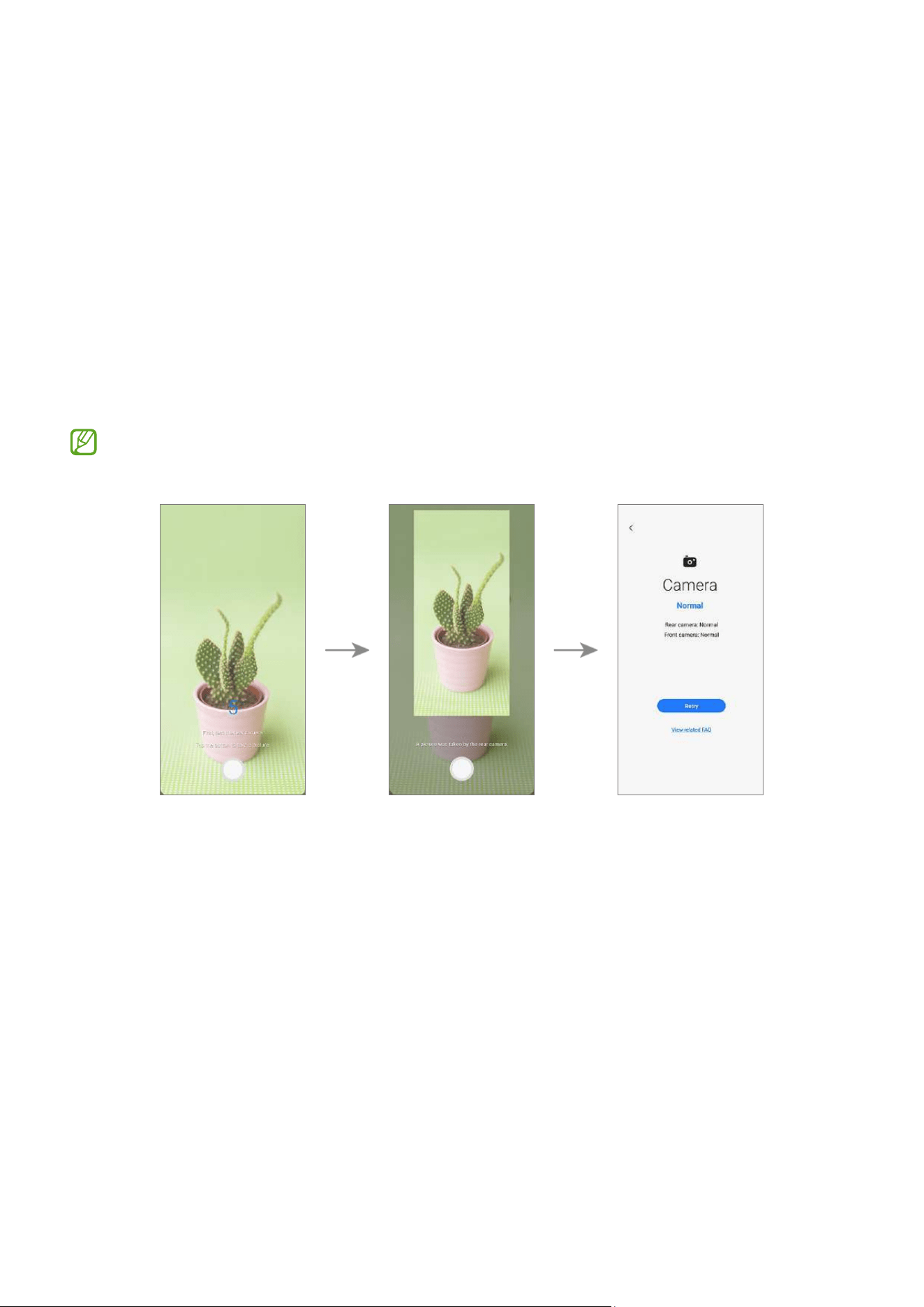
Camera
•
Function: Check whether the rear and front cameras are working normally.
•
How to check:
Tap the camera button to test the rear and front cameras.
The picture that was taken will be displayed to check the quality of the pictures.
•
Provided information
‒
Status: View the status whether the feature is working normally.
‒
Camera types: View the status of each camera.
‒
FAQ: View frequently asked questions.
To test this more accurately, check if the camera is obstructed by foreign objects,
the case, or protective film.
Quality Test
19
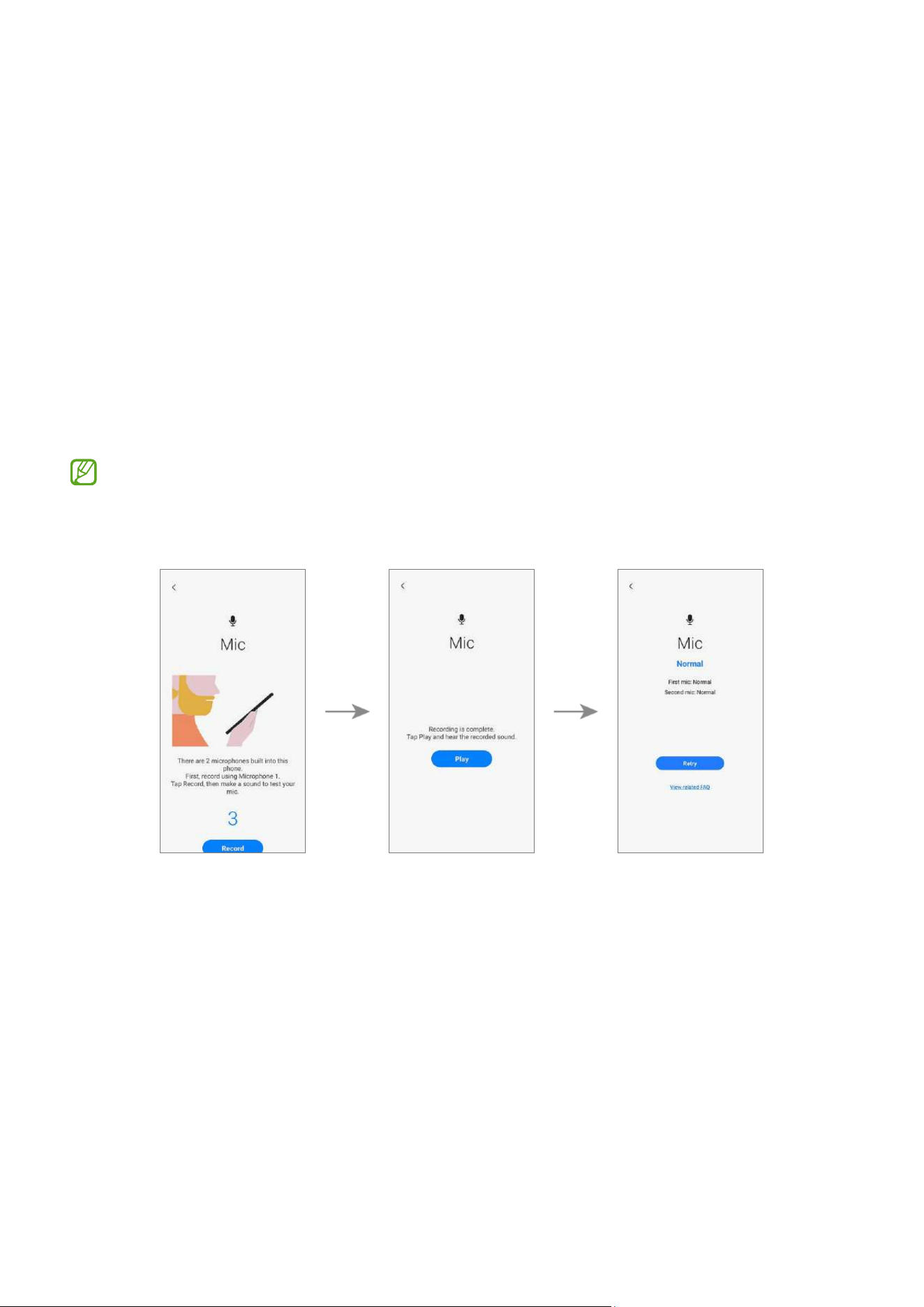
Mic
•
Function: Check whether the microphone is working normally.
•
How to check:
1) Tap
Record
and say something for the recording.
2) When the recording is finished, tap
Play
and select a button according to the
question.
•
Provided information
‒
Status: View whether the feature is working properly.
‒
Mic types: View the status of each mic.
‒
FAQ: View frequently asked questions.
•
The number of tests may vary depending on the model.
•
If you cannot hear anything after recording, check whether the media volume is
turned up.
Quality Test
20
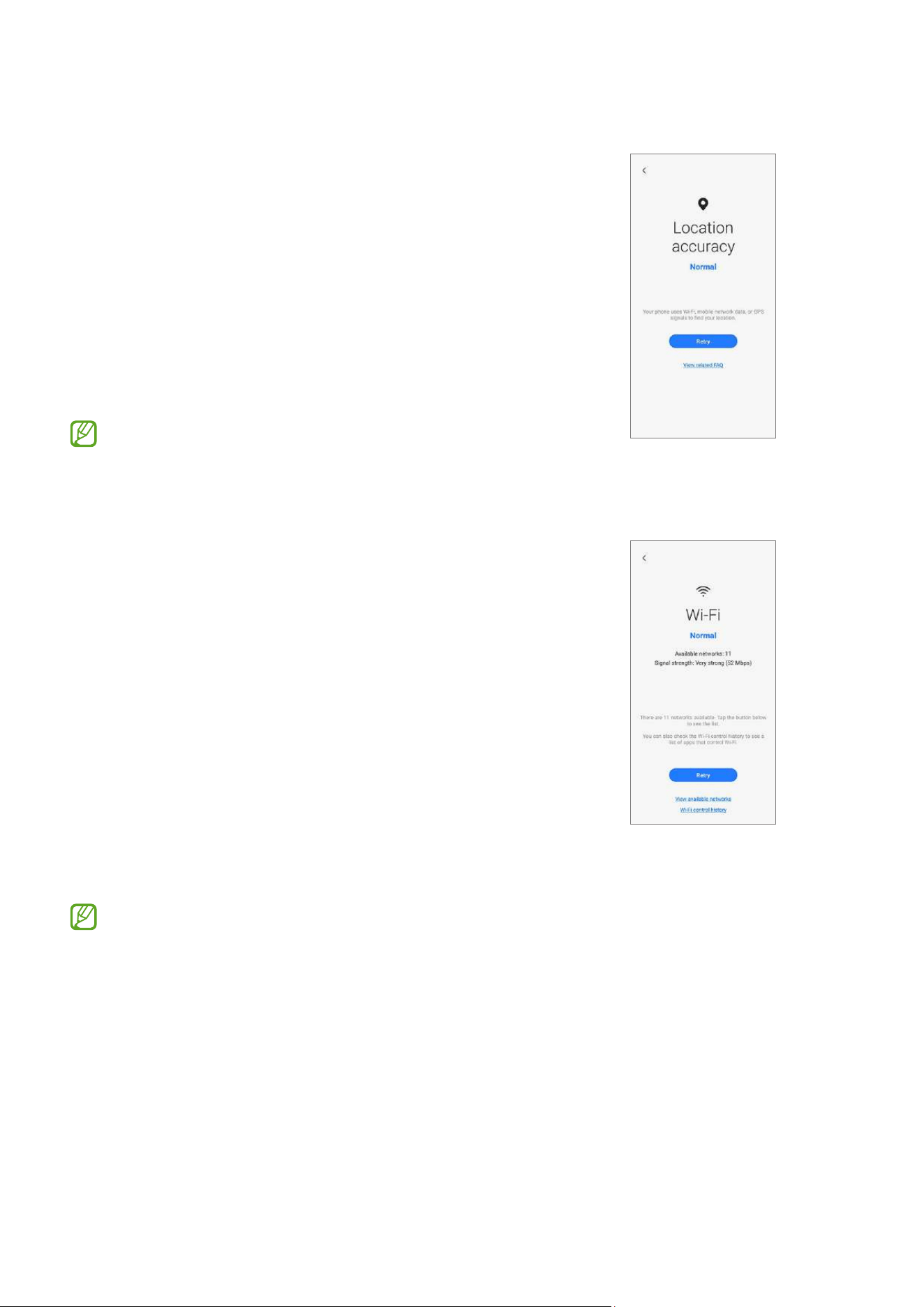
Location accuracy
•
Function: Check whether the location accuracy is
working normally.
•
How to check:
Tap
Start
.
•
Provided information
‒
Status: View whether the feature is working
normally.
‒
FAQ: View frequently asked questions.
The results might be more accurate when you
test outside.
Wi-Fi
•
Function: Check whether Wi-Fi can search for
Wi-Fi routers.
•
Provided information
‒
Status: View whether the feature is working
normally.
‒
Available networks: View the number of
available networks.
‒
Signal strength: View the signal strength of
the connected Wi-Fi router.
‒
Networks: View available networks.
‒
History: View the Wi-Fi control history.
To test this feature, the Wi-Fi feature must be
activated.
Quality Test
21
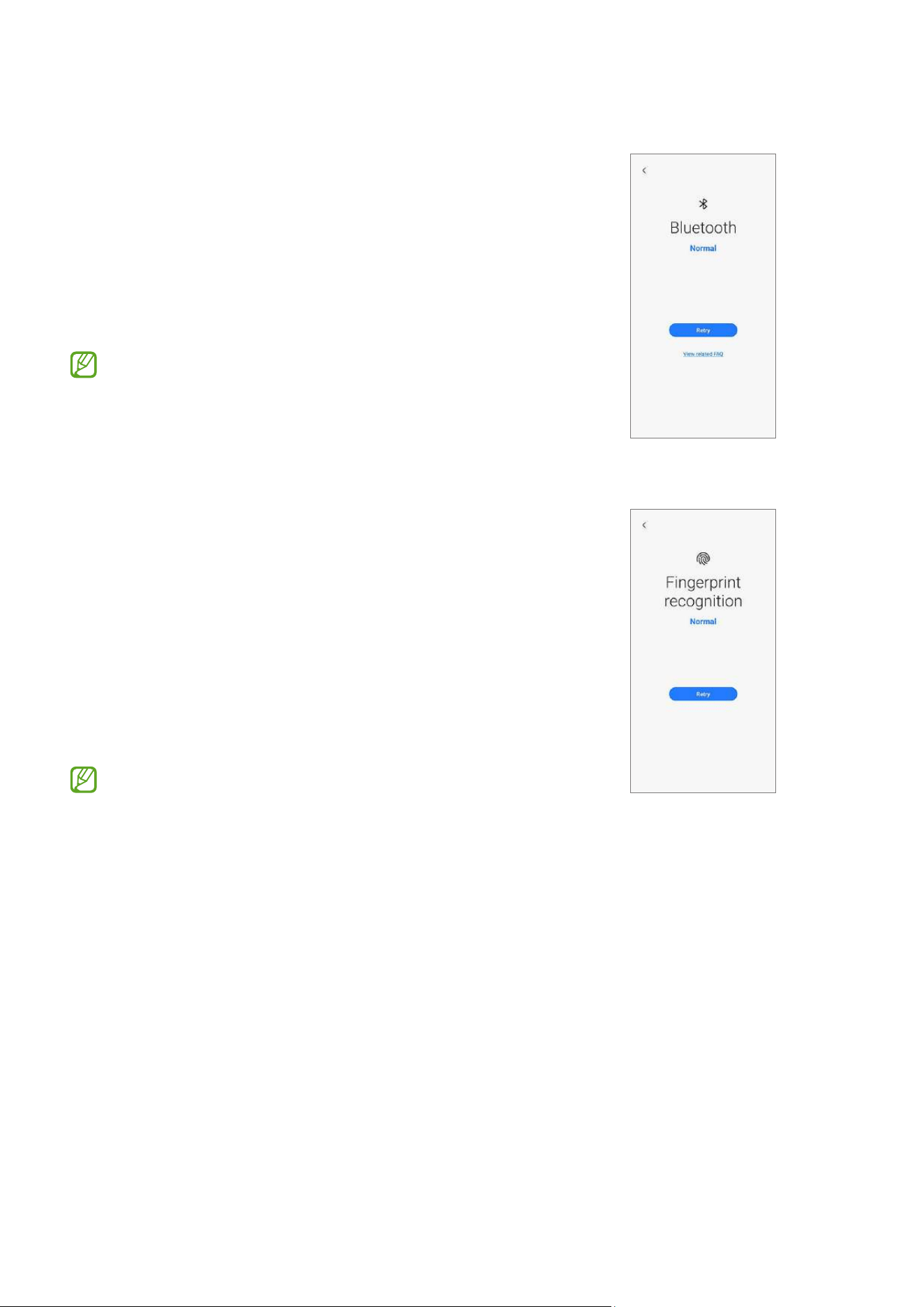
Bluetooth
•
Purpose: Check whether Bluetooth can search for
other Bluetooth devices.
•
Provided information
‒
Status: View whether the feature is working
normally.
‒
FAQ: View frequently asked questions.
To test this feature, the Bluetooth feature must
be activated.
Fingerprint recognition
•
Purpose: Check whether the fingerprint
recognition sensor is working.
•
How to check:
Place your finger on the fingerprint recognition
sensor.
•
Provided information
‒
Status: View whether the feature is working
normally.
To test this feature, your fingerprint must be
registered.
Quality Test
22
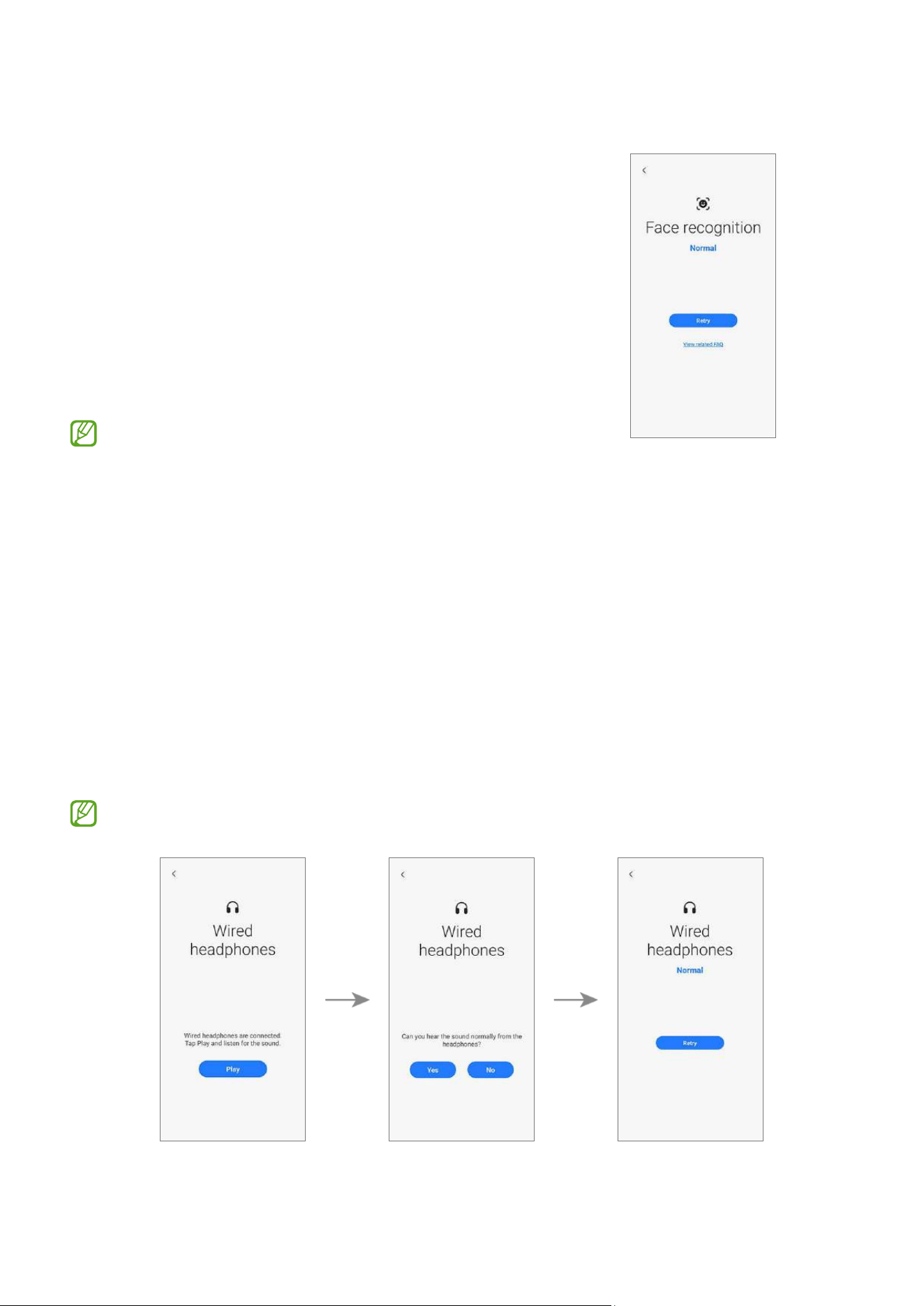
Face recognition
•
Purpose: Check whether the face recognition
sensor is working.
•
How to check:
Look at the screen.
•
Provided information
‒
Status: View whether the feature is working
normally.
‒
FAQ: View frequently asked questions.
To test this feature, your face must be
registered.
Wired headphones
•
Purpose: Check whether the headphone jack recognises the headphones normally.
•
How to check:
1) Connect headphones to your device.
2) Tap
Play
and listen for the sound.
3) Answer the question using the buttons.
•
Provided information
‒
Status: View whether the feature is working normally.
To test this feature, you must connect headphones.
Quality Test
23
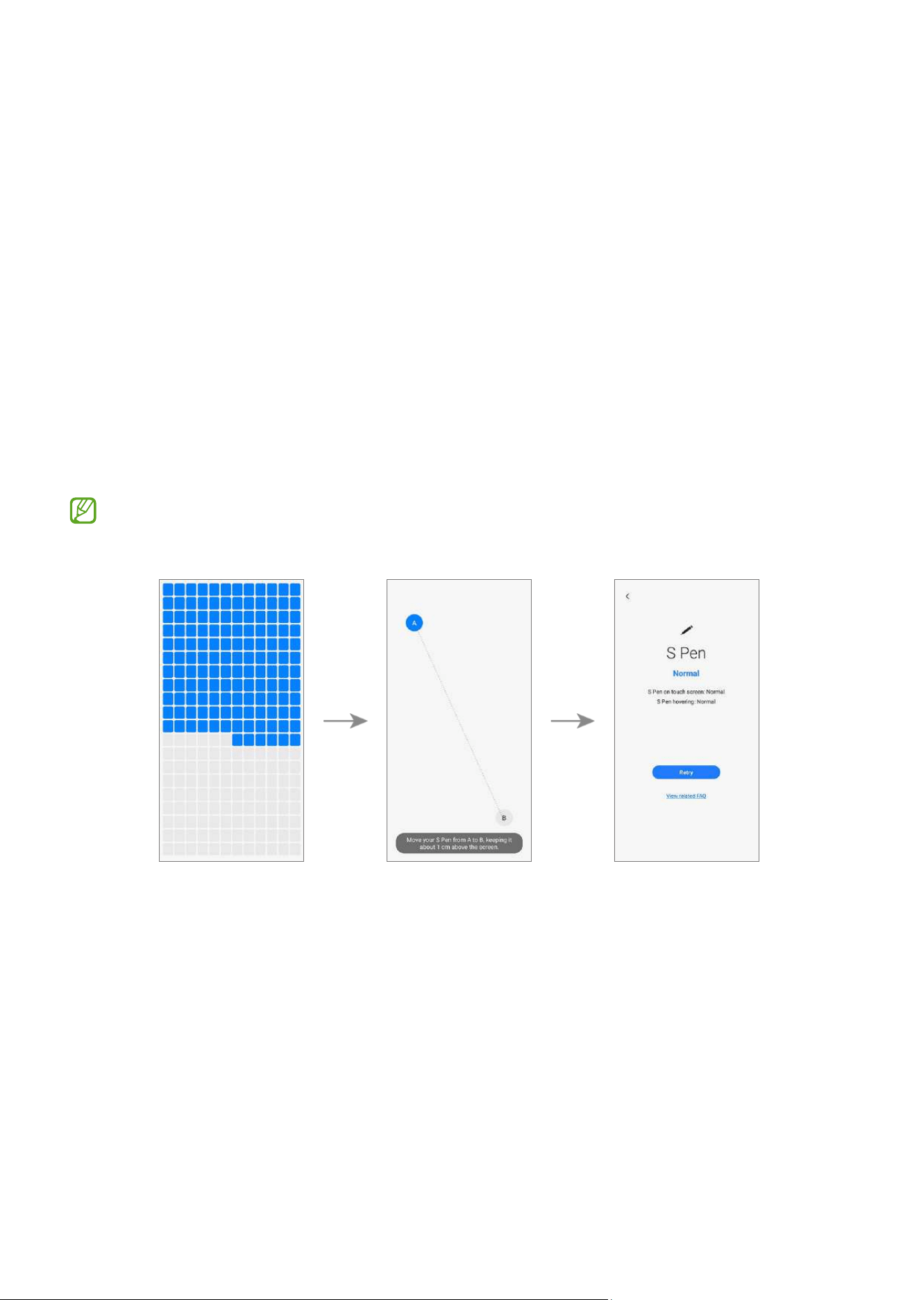
S Pen
•
Purpose: Check whether the S Pen is recognised in all areas of the touchscreen.
•
How to check:
1) Tap all the rectangles on the screen with the S Pen.
The tapped or dragged rectangles will turn blue.
2) Hover the S Pen over the screen and move from A to B.
The blue circle will move along with the S Pen.
•
Provided information
‒
Status: View whether the feature is working normally.
‒
S Pen features: View the status of S Pen features.
‒
FAQ: View frequently asked questions.
•
Make sure that the screen is clean to get more accurate test results.
•
This test is only available for the S Pen supported models.
Quality Test
24
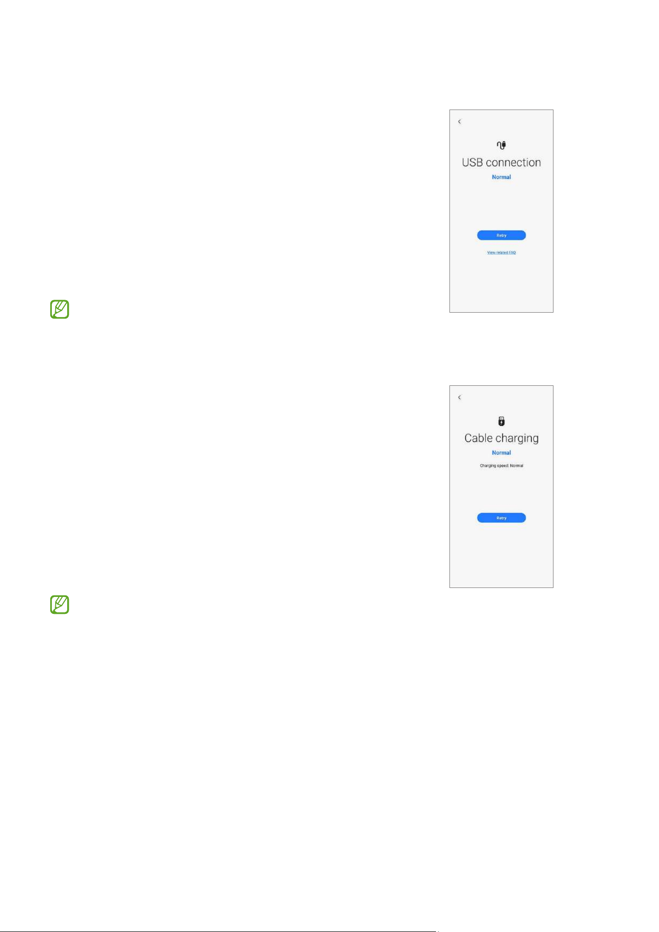
USB connection
•
Purpose: Check whether the multipurpose jack
recognises the USB cable normally.
•
How to check:
Connect any USB cable to your device.
•
Provided information
‒
Status: View whether the feature is working
normally.
‒
FAQ: View frequently asked questions.
To test this feature, the USB cable must be
connected to a computer.
Cable charging
•
Purpose: Check whether the multipurpose jack
recognises the charger normally.
•
How to check:
Connect a charger to your device.
•
Provided information
‒
Status: View whether the feature is working
normally.
‒
Charging speed: View the charging speed
according to the charger you connected.
Use only Samsung-approved chargers.
Quality Test
25
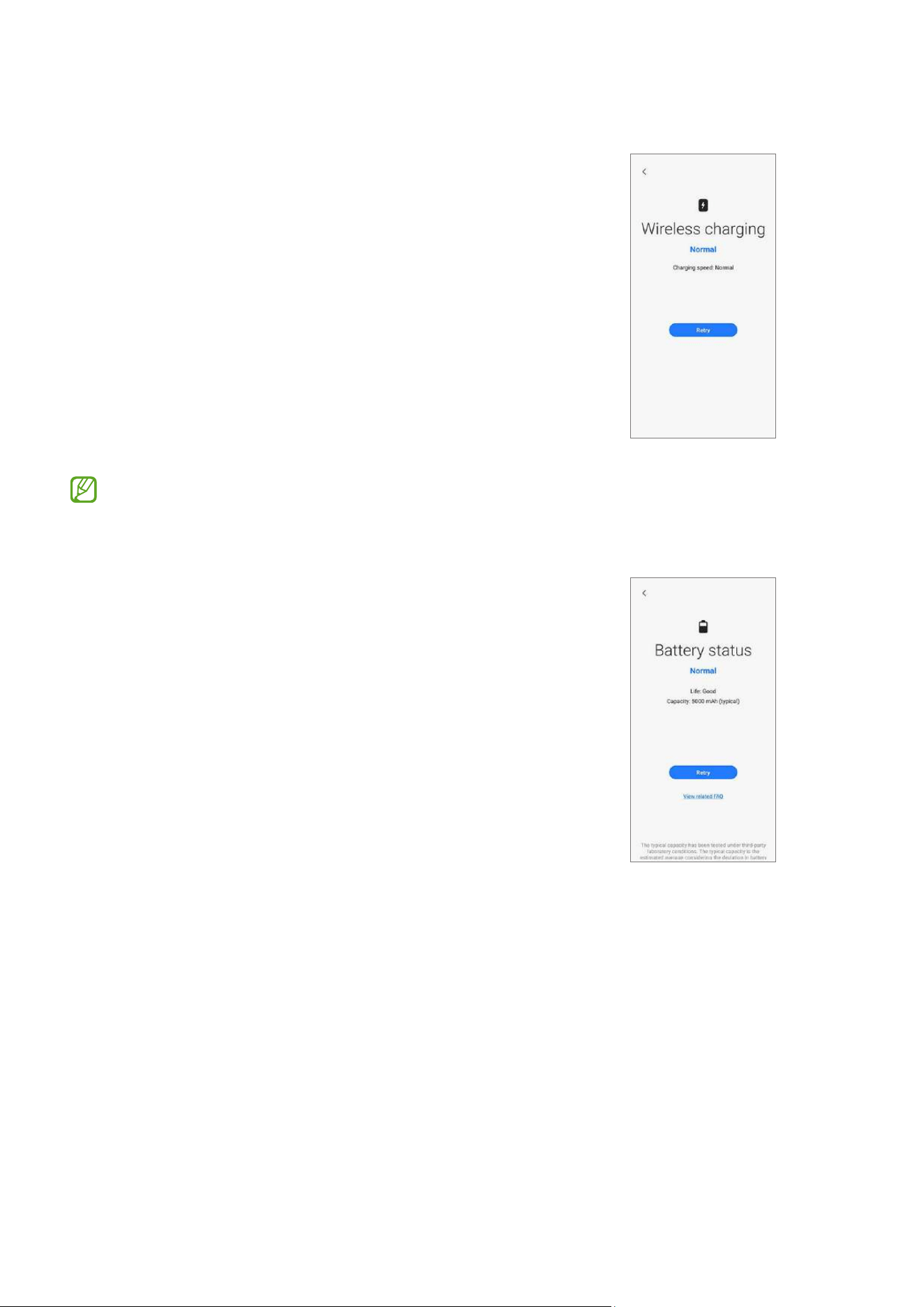
Wireless charging
•
Purpose: Check whether the wireless charging
feature is working normally.
•
How to check:
Put your device on a wireless charger.
•
Provided information
‒
Status: View whether the feature is working
normally.
‒
Charging speed: View the charging speed
according to the wireless charger you put your
device on.
Use only Samsung-approved wireless chargers.
Battery status
•
Function: Check the battery values and analysis.
•
Provided information
‒
Status: View whether the feature is working
normally.
‒
Life: View the remaining battery life
(measured by comprehensive battery values).
‒
Capacity: View the battery capacity.
‒
FAQ: View frequently asked questions.
Calibrations
26
Calibrations
Calibrations
In order to guarantee the stable and correct performance of components or sensors, it is
required to conduct calibrations through the
Self Repair Assistant
app after repair.
If the calibration results show any malfunctions, visit a Samsung Service Centre for
further action. Any malfunctions caused by your repair may incur additional repair
charges.
In order to conduct the accurate calibrations after repair, visit a Samsung Service
Centre or website to buy calibration equipment if you do not have any.
Used Parts and Calibration Functions in Supported Models
The calibration functions are automatically conducted based on the selected parts.
Screen Battery Back Glass Charging Port Speaker
Optical
Fingerprint Cal.
Yes No No No No
Range Sensor
Cal.
Yes Yes Yes Yes Yes
Battery Cycle
Resets.
No Yes No No No
Touch Screen
Panel Cal.
Yes No No No No
Speaker Cal. No No No No Yes
Under-display
Camera Cal.
Yes No No No No
Digital Hall
Sensor Cal.
Yes No No No No
Calibrations
27
•
Depending on the model, the screen module may include batteries. So when
the screen module is replaced, the battery also has to be selected and a battery
cycle reset must be performed.
•
In the Fold models, touch screen panel calibration is performed for both the
main and cover screens.
•
Digital hall sensor calibration is only for the Fold and Flip models and
under-display camera calibration is only for the Fold models.
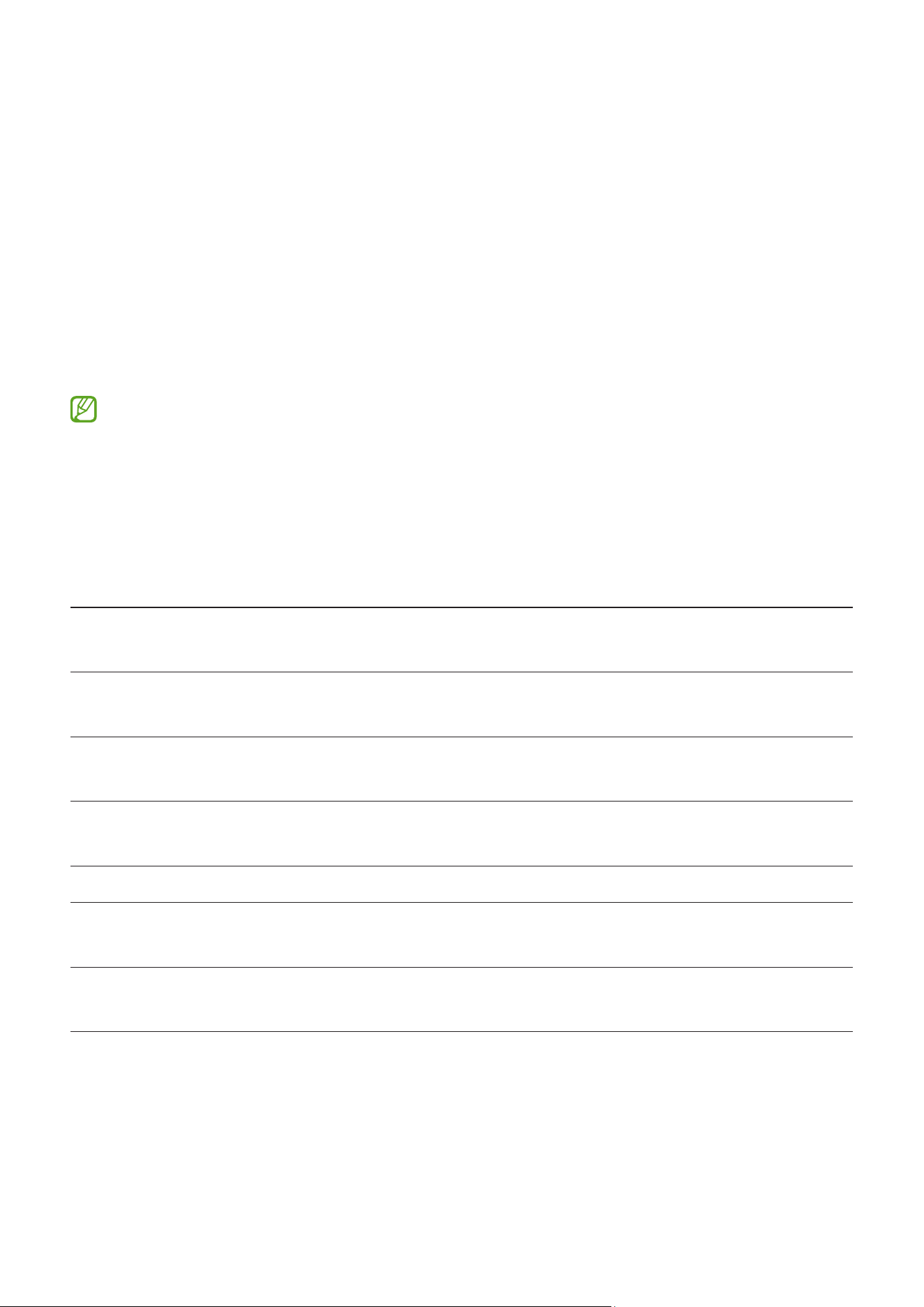
Using the Self Repair Assistant App
1 Download the
Self Repair Assistant
app from
Galaxy Store
.
For US devices, you need to install the APK file for the
Self Repair Assistant
app
manually. However, if the
Auto Blocker
function which is provided from Android
OS 14 (U OS) is turned on, you cannot install any APK files manually through the
My
Files
app. In this case, launch the
Settings
app, tap
Security and privacy
→
Auto
Blocker
, and then tap the switch to turn it off to install the
Self Repair Assistant
app.
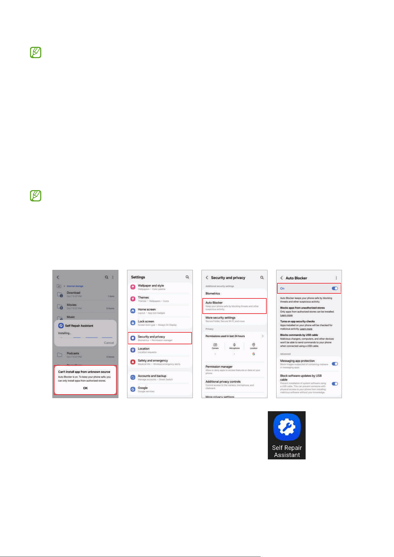
2 Launch the
Self Repair Assistant
app.
Calibrations
28
3 Read Privacy Notice and tap
Continue
.
•
If you are not signed in to your
Samsung account, a button will appear
to sign in.
•
If you select the link to read the full
Privacy Notice, you will be directed to
our site.
Calibrations
29
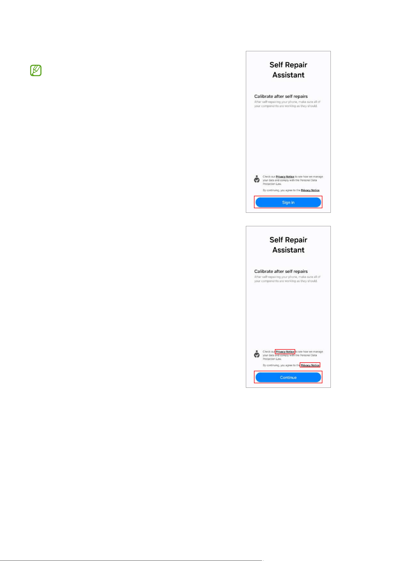
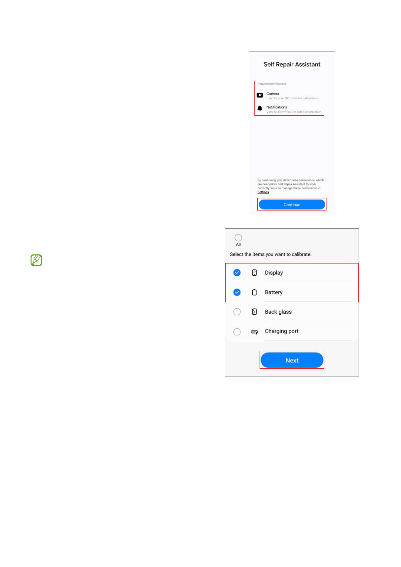
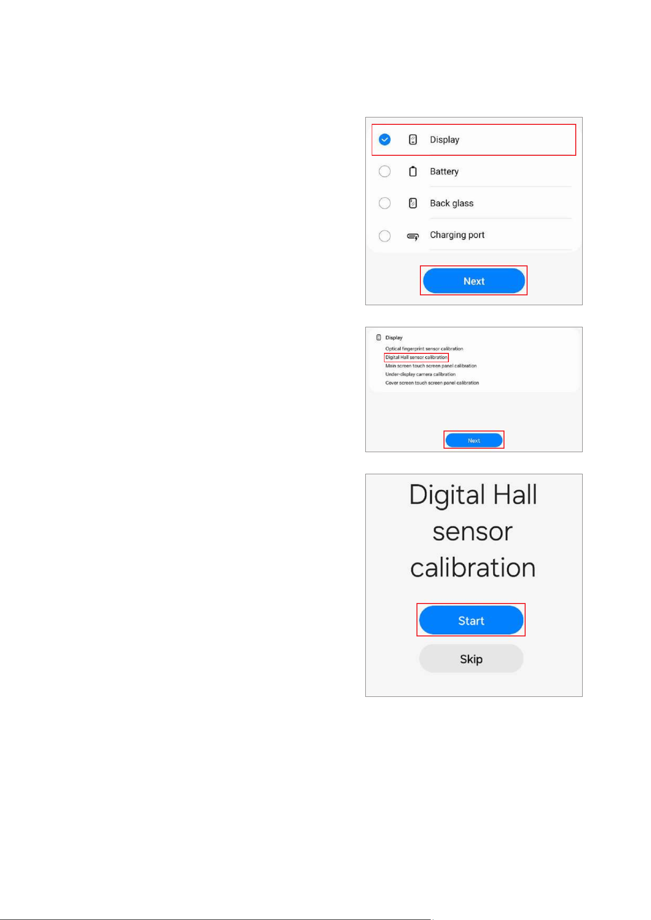
4 Check permissions and tap
Continue
.
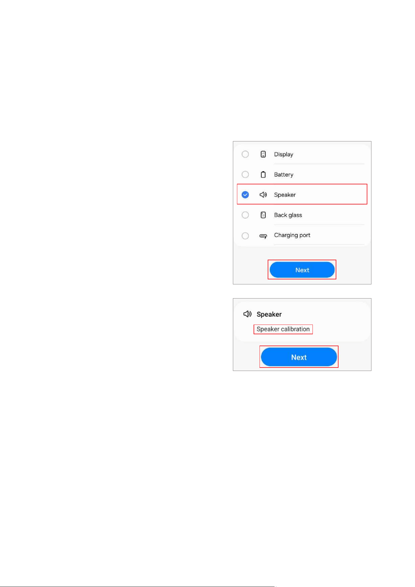
5 Select the part that you have replaced and
tap
Next
.
•
The required calibrations will be
conducted automatically.
•
If the device does not have certain
components or sensors associated
with the part that has been replaced,
relative calibration will be skipped
automatically.
Calibrations
30
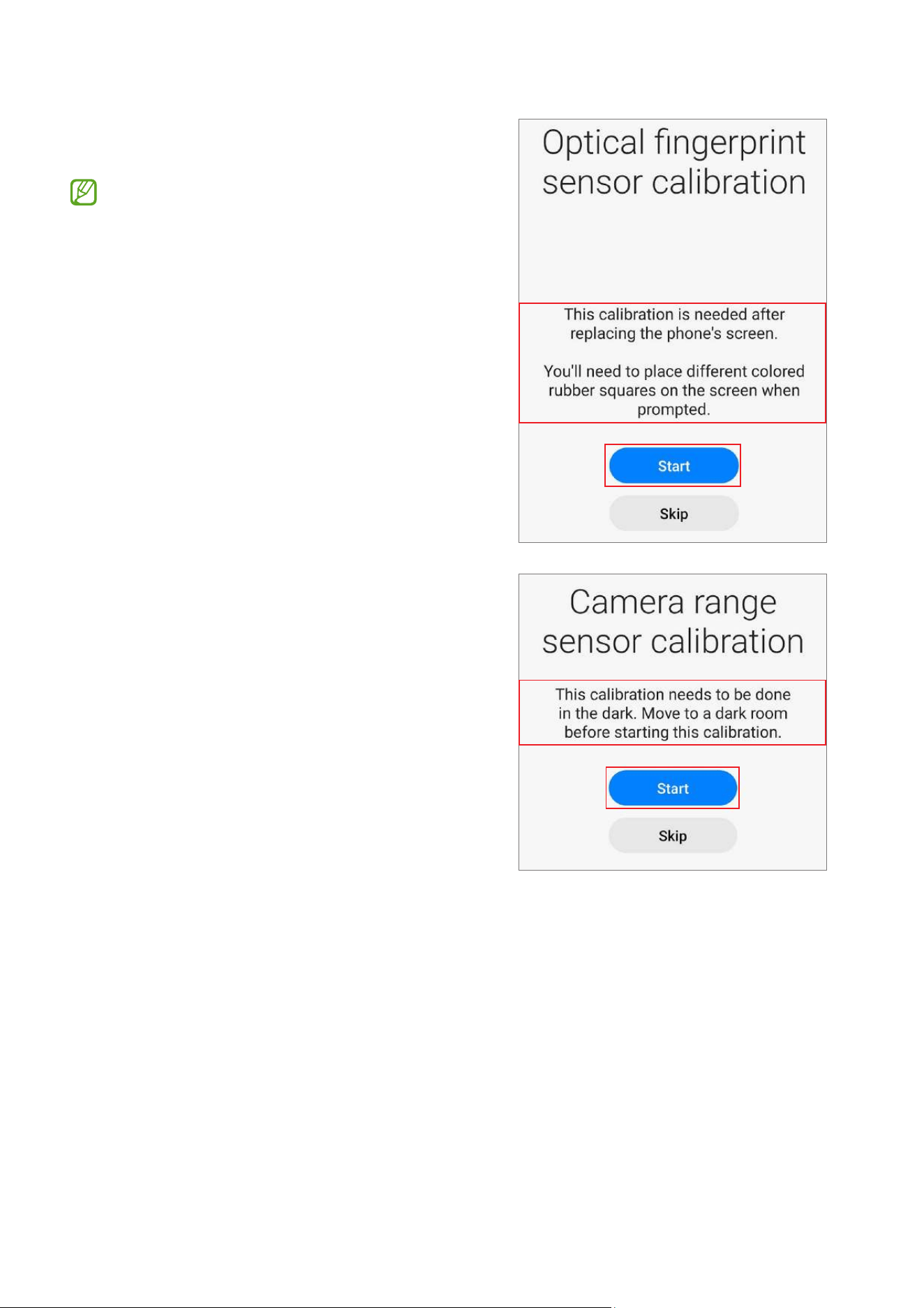
6 Read the on-screen instructions and tap
Start
.
Refer to Optical Fingerprint Sensor
Calibration, Resetting the Battery Cycle
Count, Range Sensor Calibration, Touch
Screen Panel Calibration, Speaker
Calibration, Under-display Camera
Calibration (Fold Models Only), and
Digital Hall Sensor Calibration (Fold and
Flip Models Only) for more information.
Calibrations
31
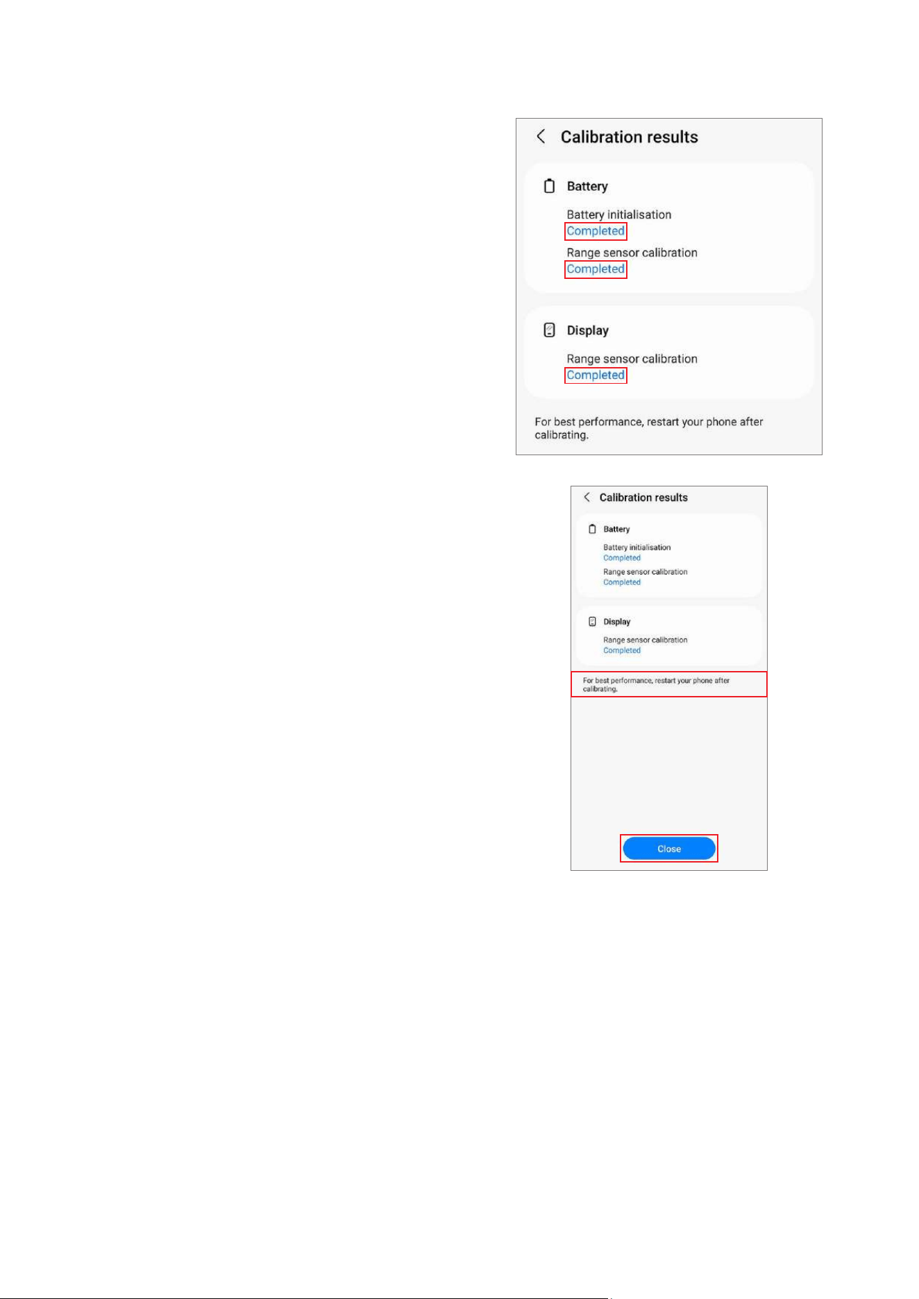
7 Check the results of each calibration item.
•
Completed
: Calibration was done
normally.
•
Failed
: Calibration failed.
•
Skipped
: Calibration was skipped.
8 On the calibration results page, tap
Close
to close the app.
Restart your device to finish calibrating.
Calibrations
32
Optical Fingerprint Sensor Calibration
Whenever the screen is replaced, the optical fingerprint sensor must be calibrated to
guarantee optimised fingerprint sensor performance for devices that have it.
Optical fingerprint sensor calibration is available through the
Self Repair Assistant
app.
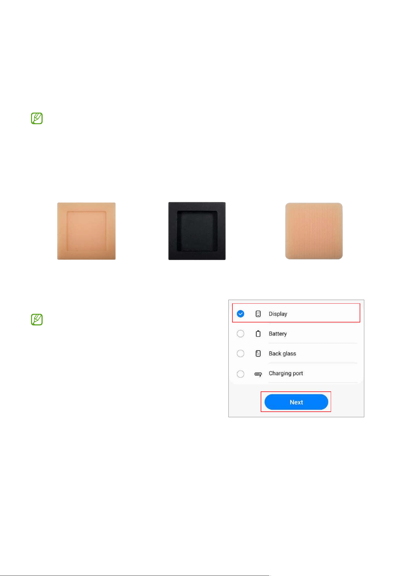
•
This feature may not be available depending on the model. The availability of
this feature can be automatically checked in the Self Repair Assistant app, so
please follow the guidance of the Self Repair Assistant app.
•
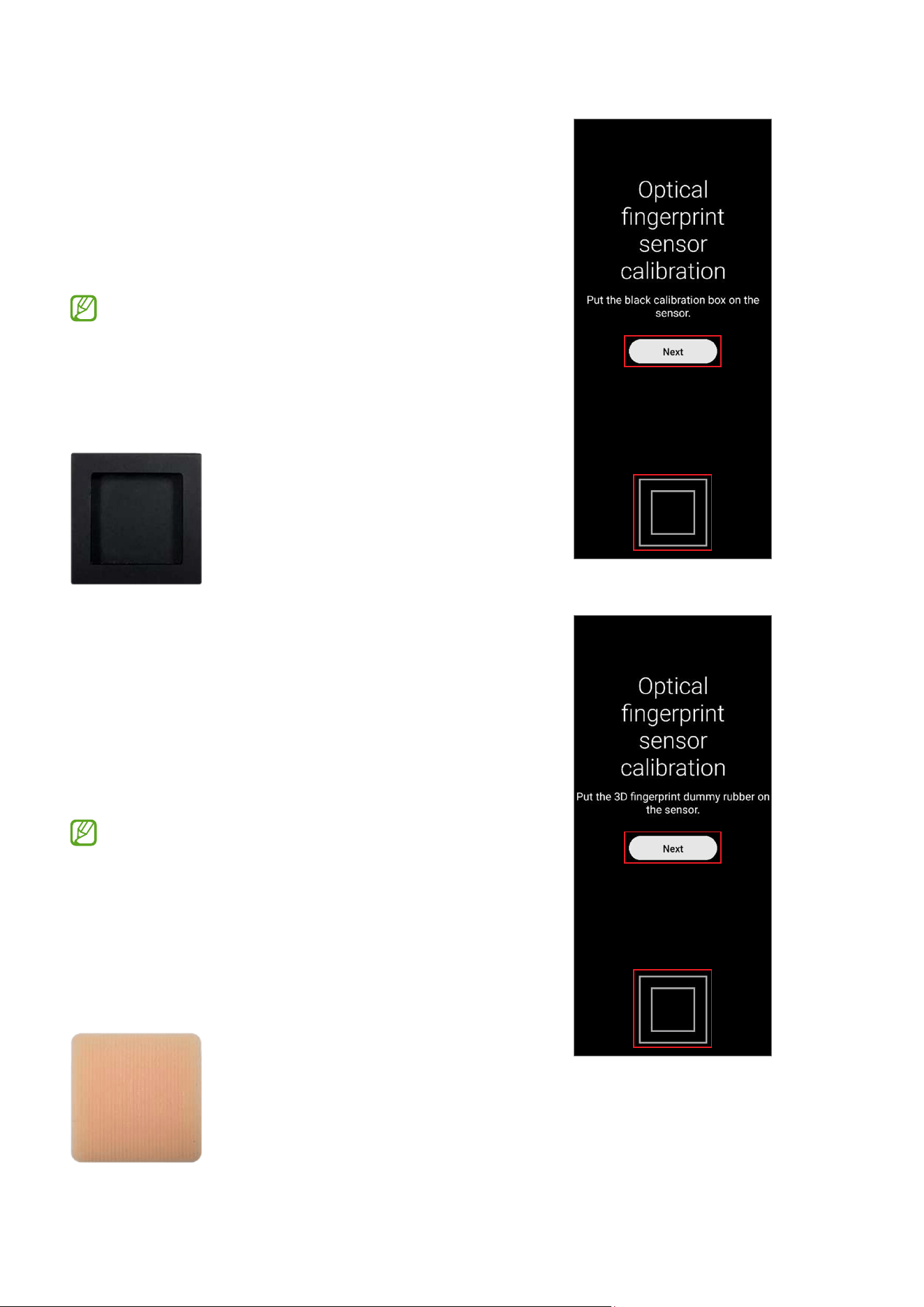
Three rubbers (the white calibration box, the black calibration box, and the 3D
fingerprint dummy rubber) are required to start this calibration.
White calibration box Black calibration box 3D fingerprint dummy rubber
1 Launch the
Self Repair Assistant
app.
2 Tap
Display
→
Next
.
•
The required calibration or test items
will be processed automatically.
•
If the device does not have certain
components or sensors associated
with the part that has been replaced,
relative calibration will be skipped
automatically.
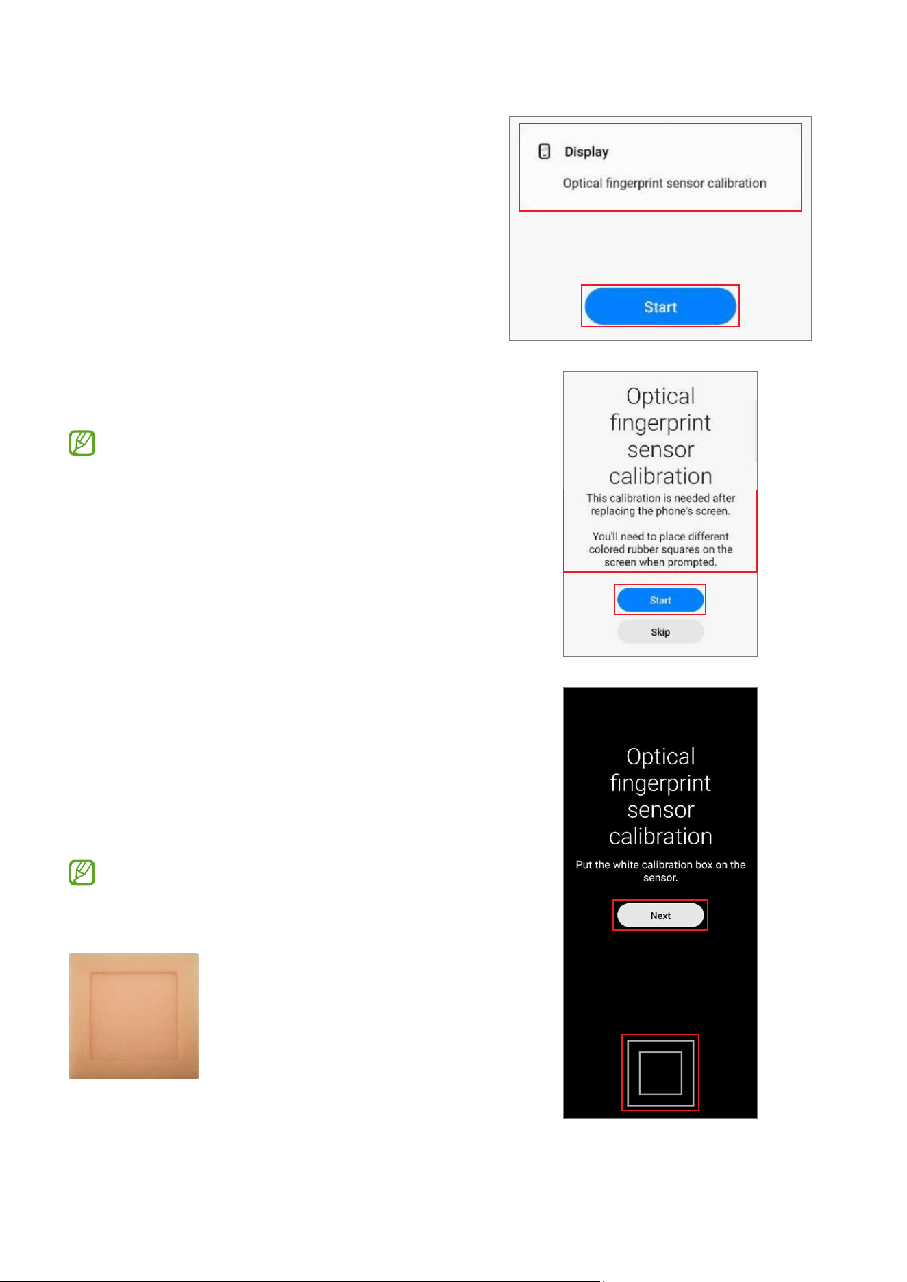
Calibrations
33
3 Check the part and calibration and then tap
Start
.
4 Read the on-screen instructions and tap
Start
.
The white calibration box must be
prepared before you start.
5 Put the white calibration box on the sensor
area (below the square side) and push the
rubber by applying force with your finger.
Tap
Next
and keep pushing the rubber
with your finger until you see the success
message.
The bottom side of the rubber that is
shaped like a square should be located
on the square guide line.
Calibrations
34
6 Put the black calibration box on the sensor
area (below the square side) and push the
rubber by applying force with your finger.
Tap
Next
and keep pushing the rubber
with your finger until you see the success
message.
•
The black calibration box must be
prepared before you start.
•
The bottom side of the rubber that is
shaped like a square should be located
on the square guide line.
7 Put the 3D fingerprint dummy rubber on
the sensor area (below the square side) and
push the rubber by applying force with your
finger.
Tap
Next
and keep pushing the rubber
with your finger until you see the success
message.
•
The 3D fingerprint dummy rubber
must be prepared before you start.
•
The bottom side of the rubber that is
shaped like a square should be located
on the square guide line. (Do not place
the pattern horizontally on the 3D
fingerprint dummy rubber.)
Calibrations
35
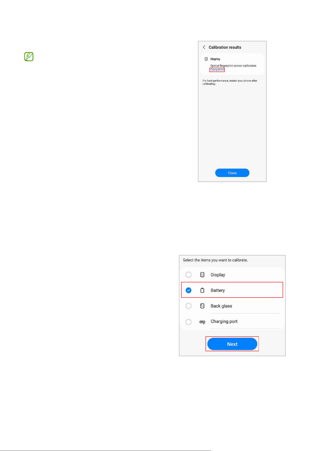
8 Check the result of the calibration.
Completed
appears only when the
calibration is successfully completed.
If
Completed
does not appear, try
calibrating again.
Resetting the Battery Cycle Count
The battery cycle count should be reset whenever your device’s battery is replaced.
1 Launch the
Self Repair Assistant
app.
2 Select the part that you have replaced.
Tap
Battery
→
Next
.
Calibrations
36
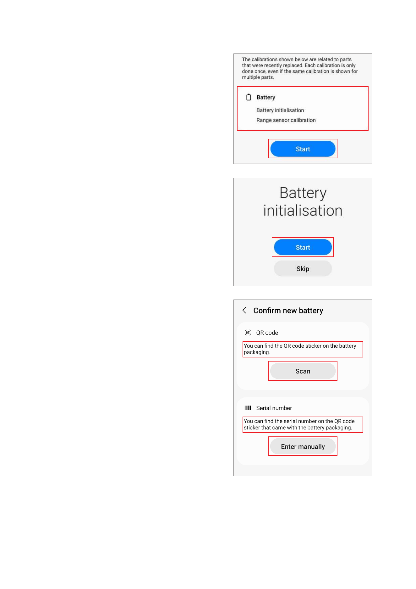
3 Check part and calibration and tap
Start
.
4 Tap
Start
.
5 Read the on-screen instructions and tap
Scan
to scan the QR code, or tap
Enter
manually
to enter the serial number
manually.
Calibrations
37
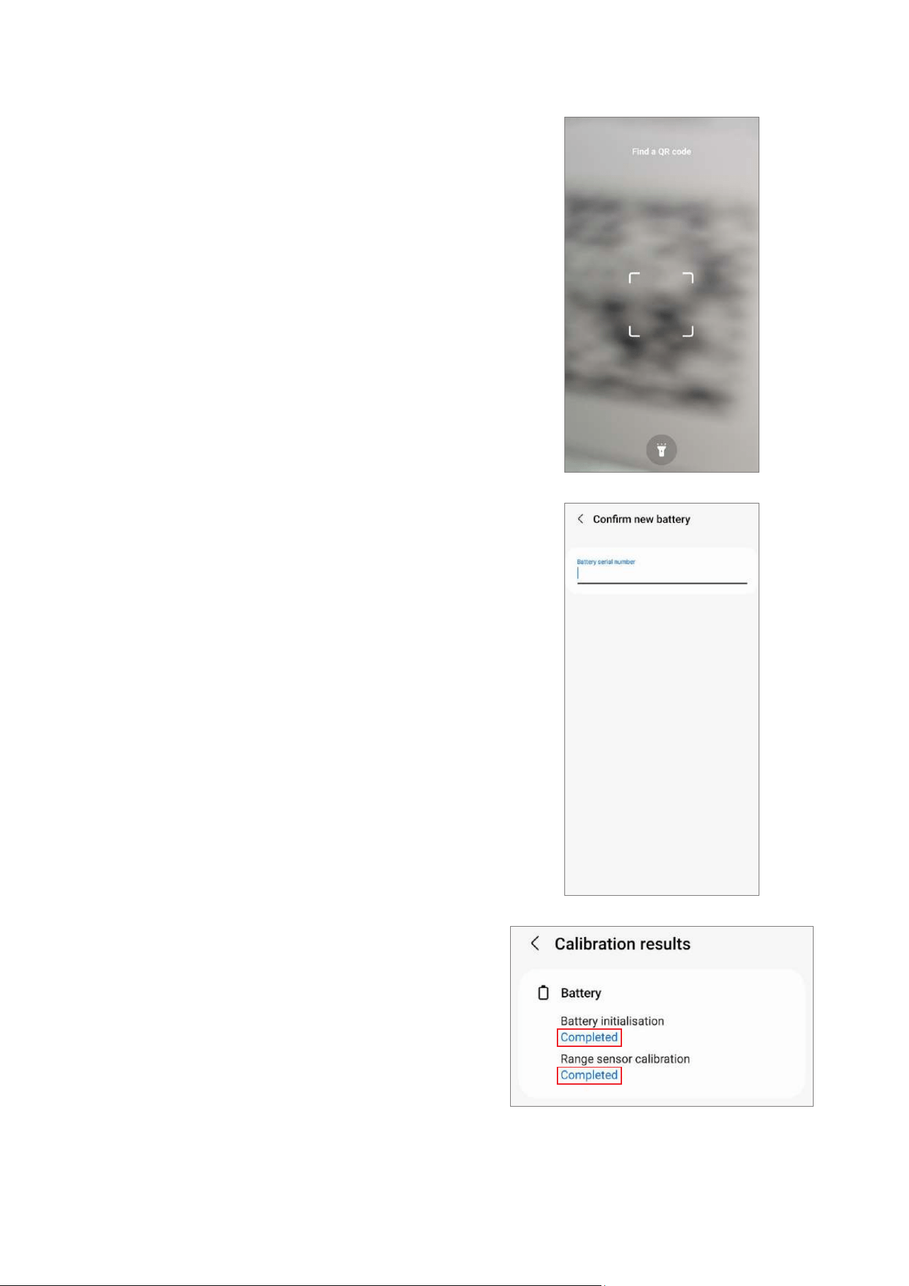
6 Scan the QR code or enter the serial
number that appears on the battery
package.
The reset will begin.
7 Check the calibration results.
Calibrations
38
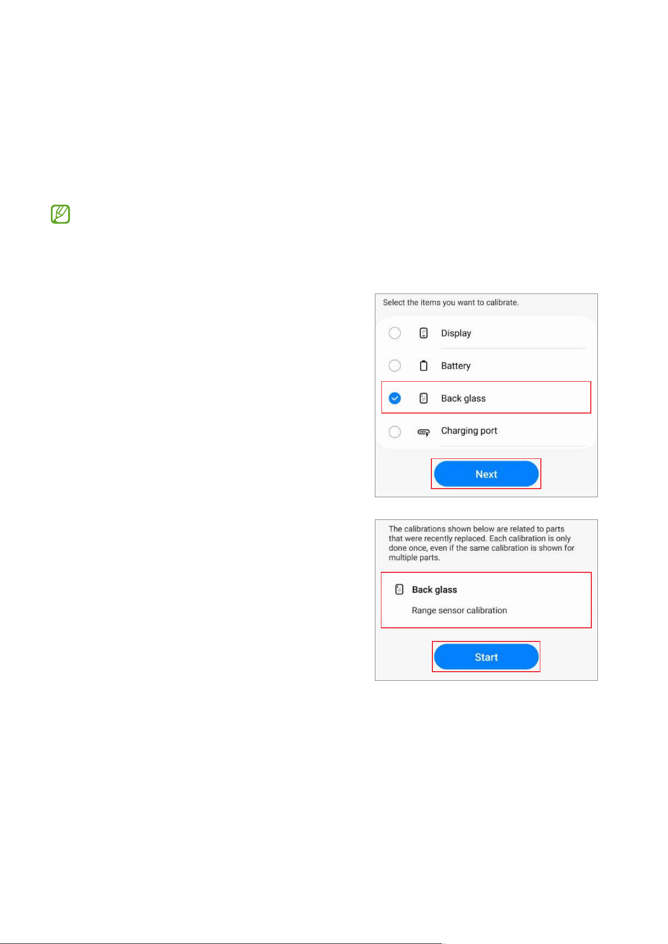
Range Sensor Calibration
When replacing screens, batteries, back glasses, or charging ports, range sensor
calibration is required to ensure the range sensors of devices equipped with them are
optimised.
Range sensor calibration is available through the
Self Repair Assistant
app.
Some content may differ from your device depending on the region, service
provider, model specifications, or device’s software.
1 Launch the
Self Repair Assistant
app.
2 Select the part that you have replaced and
tap
Next
.
3 Check part and calibration and tap
Start
.
Calibrations
39
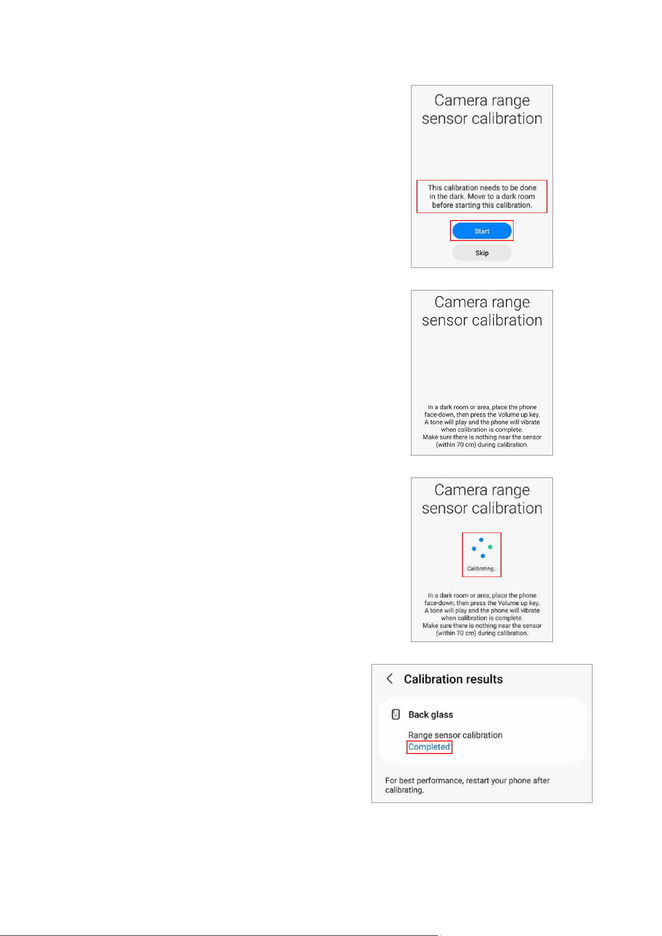
4 Read the on-screen instructions and tap
Start
.
5 In a dark room or area, place the phone
face-down, then press the Volume button.
6 The calibration will perform automatically.
A tone will play when calibration is
complete.
7 Check the calibration result.
Calibrations
40
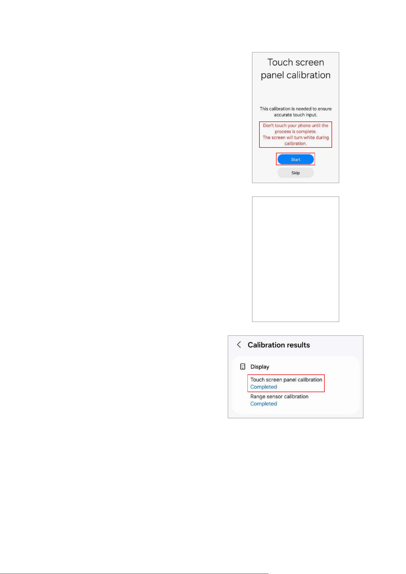
Touch Screen Panel Calibration
When replacing screens, touch screen panel calibration is required to ensure accurate
touch input.
Touch screen panel calibration is available through the
Self Repair Assistant
app.
In the Fold models, touch screen panel calibration is performed for both the main
and cover screens.
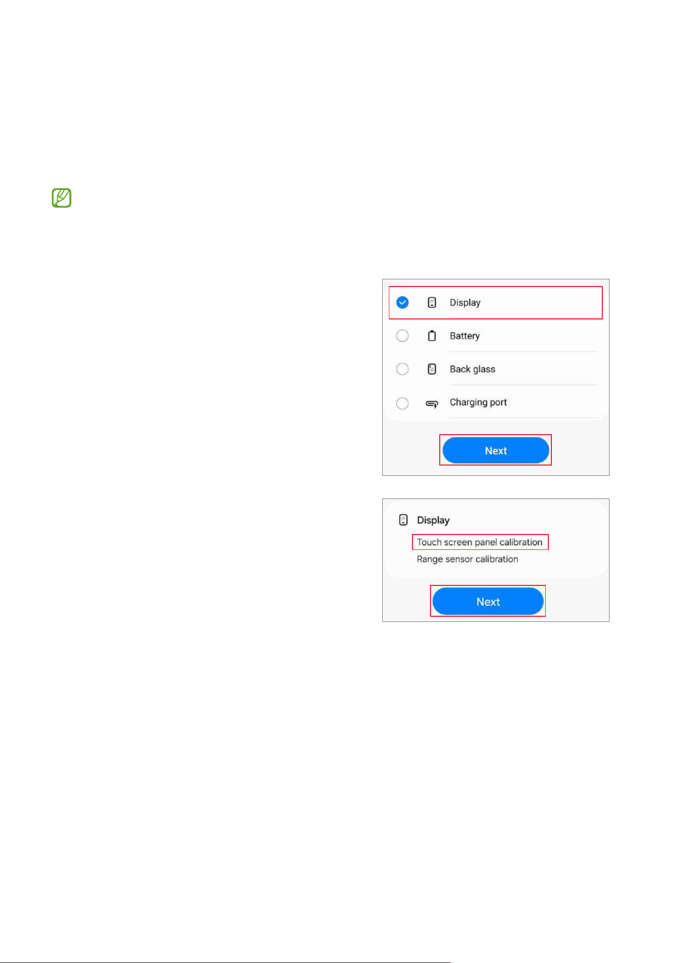
1 Launch the
Self Repair Assistant
app.
2 Select the part that you have replaced and
tap
Next
.
3 Check part and calibration and tap
Next
.
Calibrations
41
4 Read the on-screen instructions and tap
Start
.
5 The calibration will perform automatically
and the screen will turn white during
calibration.
6 Check the calibration result.
Calibrations
42
Speaker Calibration
When replacing speakers, the speaker must be calibrated to guarantee optimised
speaker performance for devices that have it.
Speaker calibration is available through the
Self Repair Assistant
app.
1 Launch the
Self Repair Assistant
app.
2 Select the part that you have replaced and
tap
Next
.
3 Check part and calibration and tap
Next
.
Calibrations
43
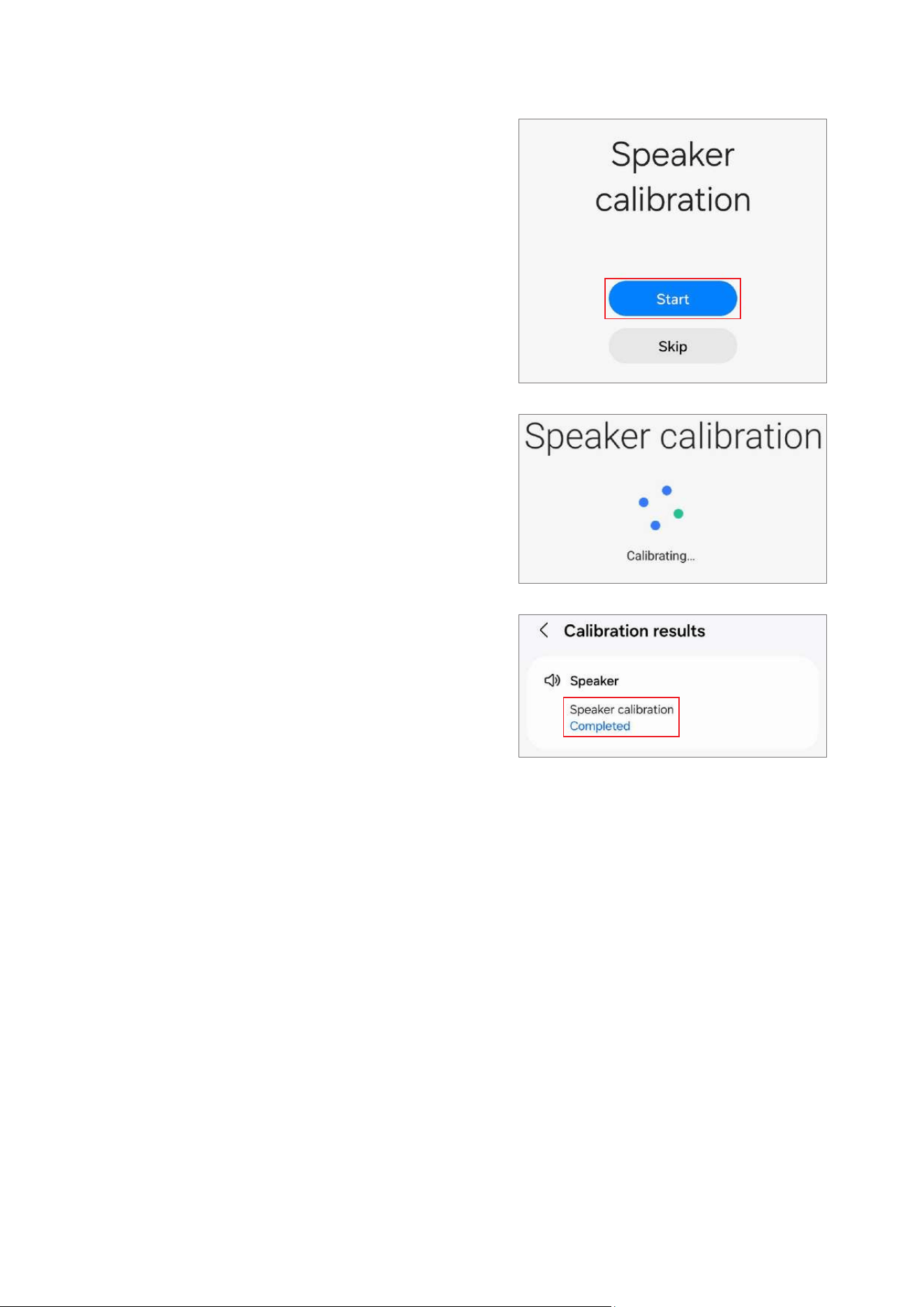
4 Tap
Start
.
5 The calibration will perform automatically.
6 Check the calibration result.
Calibrations
44
Under-display Camera Calibration (Fold Models Only)
Whenever the screen is replaced, the under-display camera must be calibrated to
guarantee optimised under-display camera performance for devices that have it.
Under-display camera calibration is available through the
Self Repair Assistant
app.
This feature may not be available depending on the model. The availability of this
feature can be automatically checked in the Self Repair Assistant app, so please
follow the guidance of the Self Repair Assistant app.
1 Launch the
Self Repair Assistant
app.
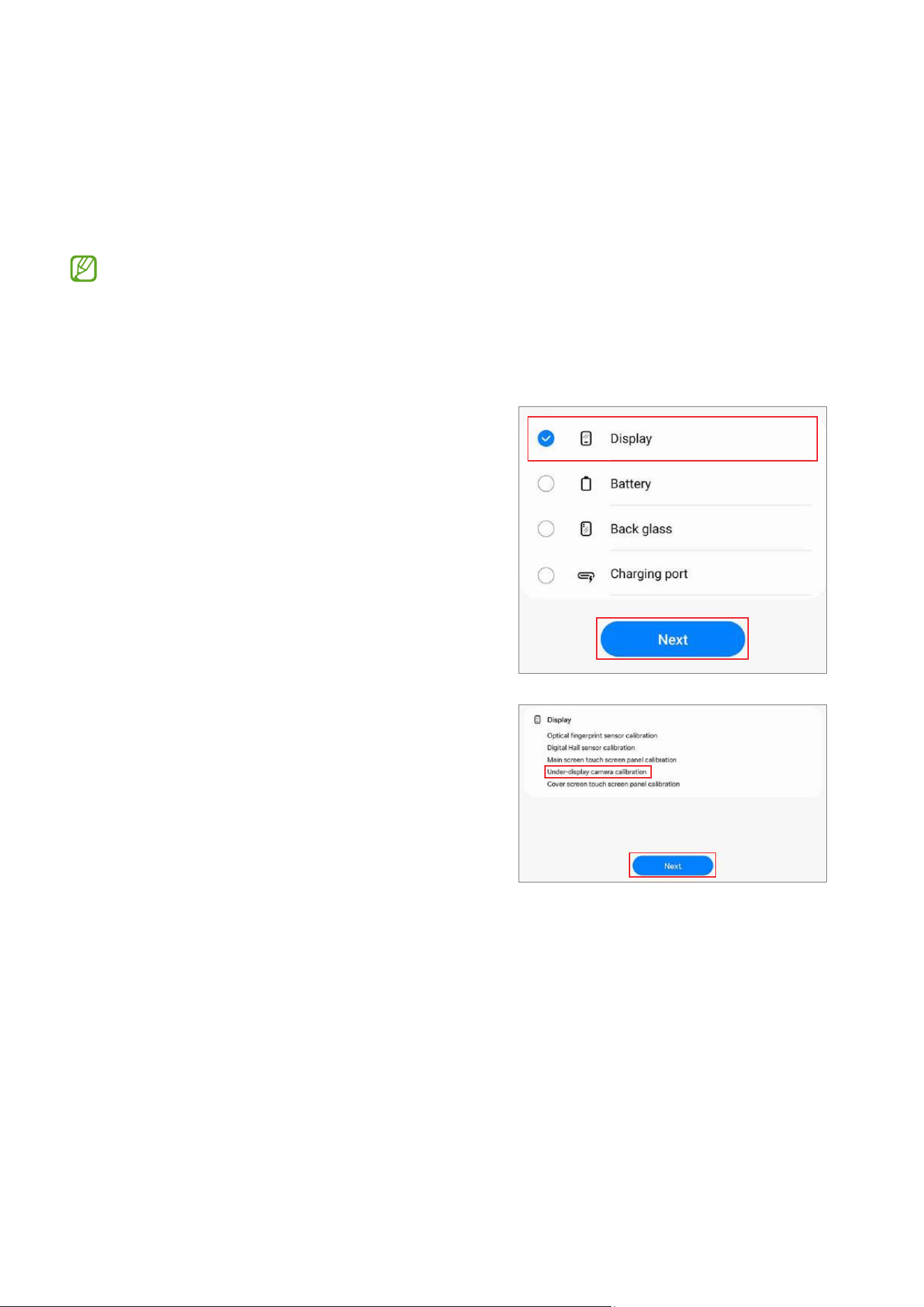
2 Select the part that you have replaced and
tap
Next
.
3 Check part and calibration and tap
Next
.
Calibrations
45
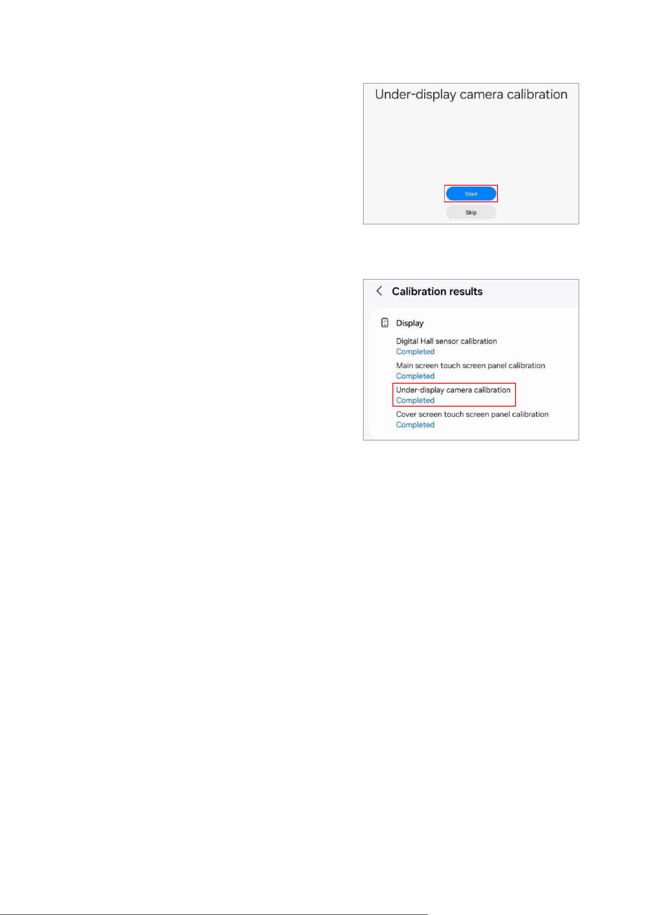
4 Tap
Start
.
5 The calibration will perform automatically.
6 Check the calibration result.

Calibrations
46
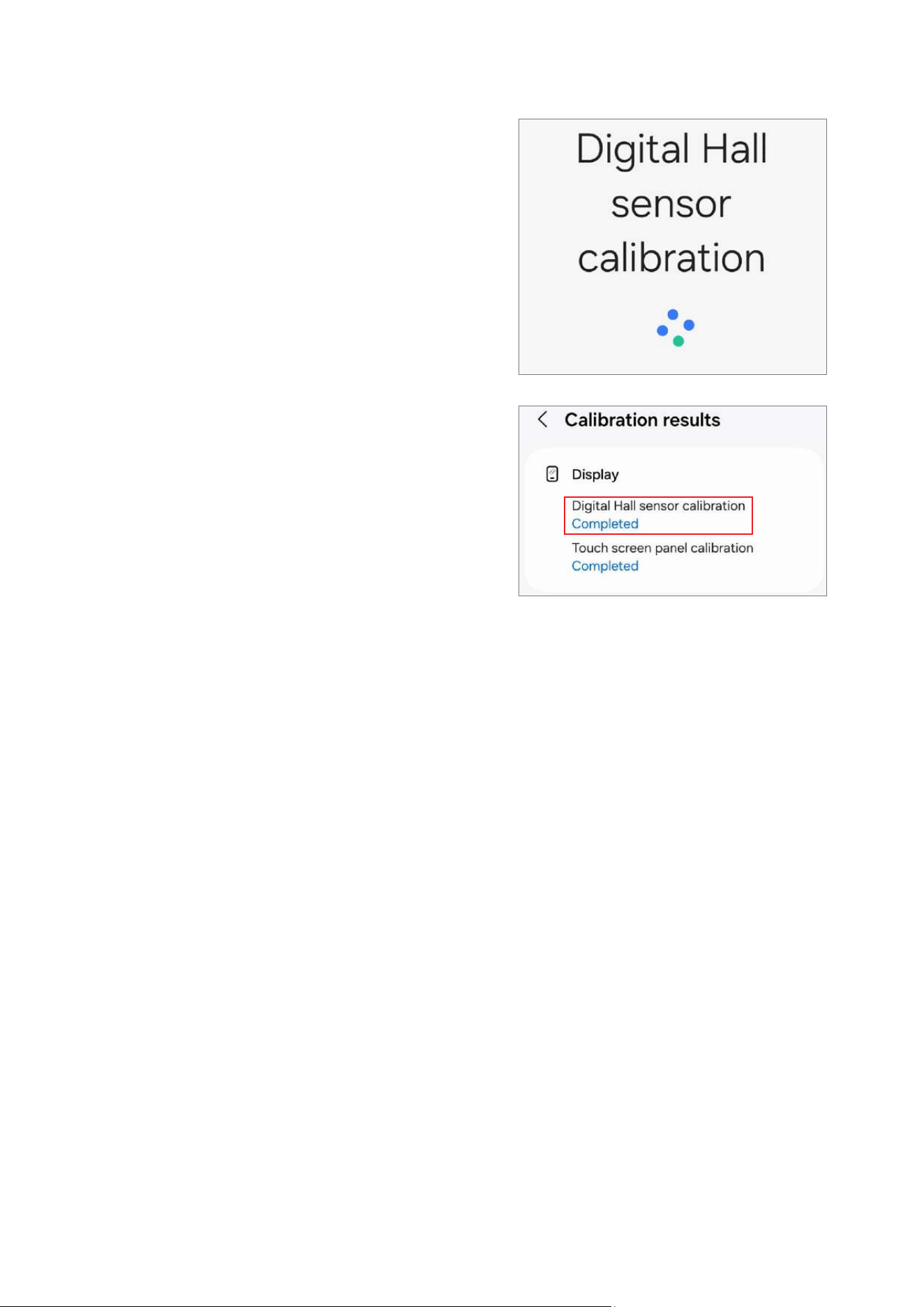
Digital Hall Sensor Calibration (Fold and Flip Models Only)
Whenever the screen is replaced, the digital hall sensor must be calibrated to guarantee
optimised digital hall sensor performance for devices that have it.
Digital hall sensor calibration is available through the
Self Repair Assistant
app.
•
This feature may not be available depending on the model. The availability of
this feature can be automatically checked in the Self Repair Assistant app, so
please follow the guidance of the Self Repair Assistant app.
•
For Fold models: If the main screen does not turn on after being replaced (the
main screen is off and the cover screen is on when the device is unfolded),
follow the steps below to perform digital hall sensor calibration. The boot
screen (the screen where the Samsung and carrier logos appear) will appear
normally and then turn off, so it is not a hardware failure.
1) Fold the device and launch the
Self Repair Assistant
app on the cover
screen.
2) Move to the digital hall sensor calibration screen, unfold the device, and
then press the Volume Up button or the Volume Down button.
3) You will hear a vibration, and the calibration will be performed
automatically.
When calibration is complete, the main screen will turn on normally.
•
For Flip models: If the main screen does not turn on after being replaced (the
main screen is off and the cover screen is on when the device is unfolded),
follow the steps below to force the main screen to turn on and perform digital
hall sensor calibration. The boot screen (the screen where the Samsung and
carrier logos appear) will appear normally and then turn off, so it is not a
hardware failure.
1) Connect the USB cable to the device, and connect the other end of the USB
cable to the USB power adapter or your computer.
2) While pressing and holding the Side button, press the Volume Up button
once and the Volume Down button twice.
3) When the main screen turns on, perform digital hall sensor calibration.
Calibrations
47
1 Launch the
Self Repair Assistant
app.
2 Select the part that you have replaced and
tap
Next
.
3 Check part and calibration and tap
Next
.
4 Tap
Start
.
Calibrations
48
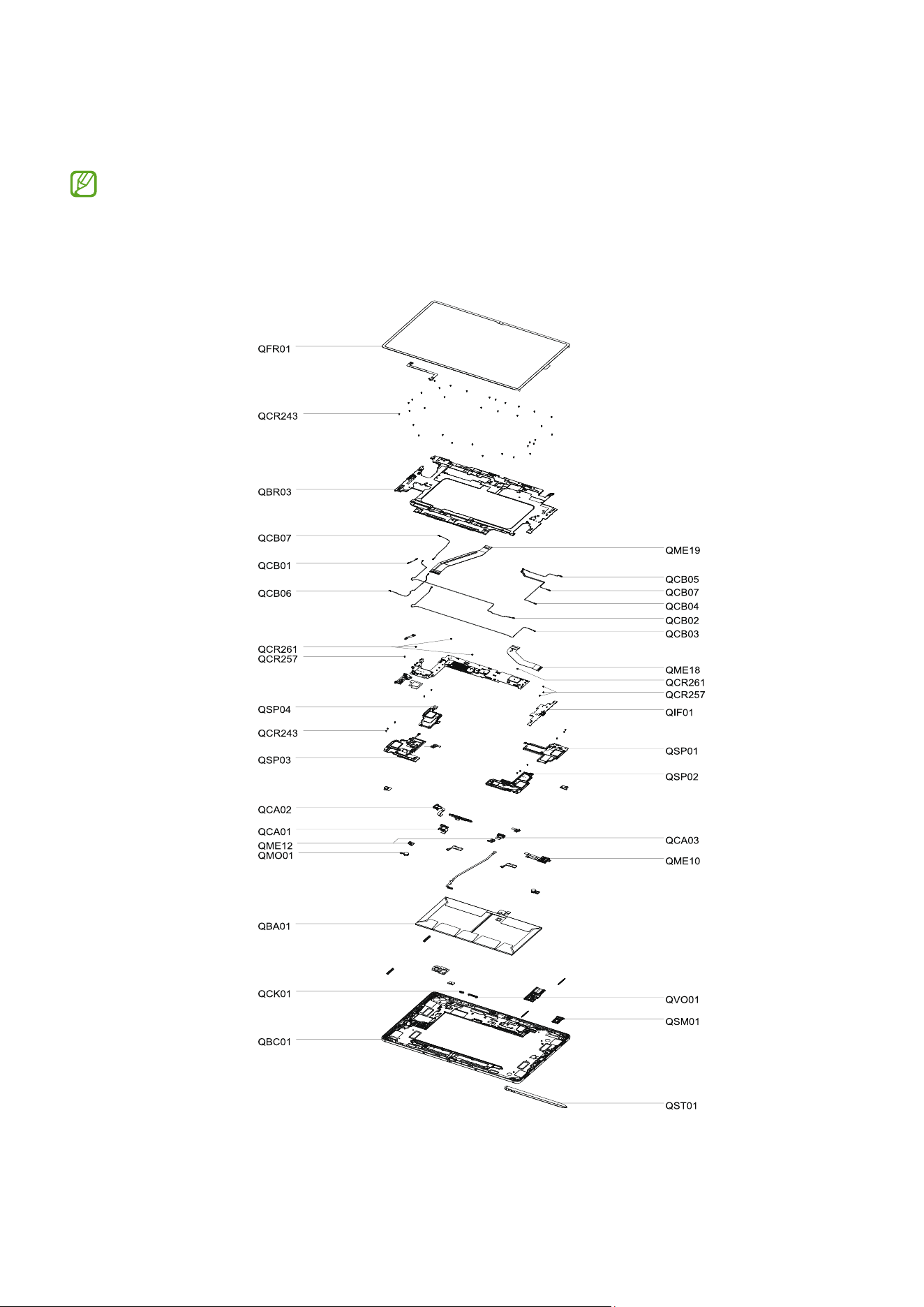
5 The calibration will perform automatically.
6 Check the calibration result.
Exploded View and Parts List
49
Exploded View and Parts List
The product’s composition may vary depending on the country, region, or carrier.
Exploded View

Exploded View and Parts List
50
Parts List
Number Name
QCR243 Screw 3405
QCR261 Screw 3463
QME19 Main Flex Cable (Screen to PBA)
QCR257 Screw 3443
QMO01 Vibrator Motor
QCB01 Antenna Flex Cable (Red)
QCB05 Antenna Flex Cable (Grey)
QCB07 Antenna Flex Cable (Orange)
QCB06 Antenna Flex Cable (Black)
QCB03 Antenna Flex Cable (White)
QCB02 Antenna Flex Cable (Blue)
QCB04 Antenna Flex Cable (Red)
QME10 SIM Card Socket
QME18 Main Flex Cable (Sub PBA to PBA)
QCK01 Side Button
QVO01 Volume Button
QST01 S pen
QCA03 Front Camera
QCA02 Rear Camera (Ultra Wide)
QCA01 Rear Camera (Wide)
QBR03 Bracket
QME12 Microphone
QSM01 SIM Card Tray
QBC01 Back cover module
QIF01 Charging Port

Exploded View and Parts List
51
Number Name
QSP04 Speaker2
QSP03 Speaker1
QSP02 Speaker4
QSP01 Speaker3
QFR01 Screen
QBA01 Battery
Disassembly and Assembly
52
Disassembly and Assembly
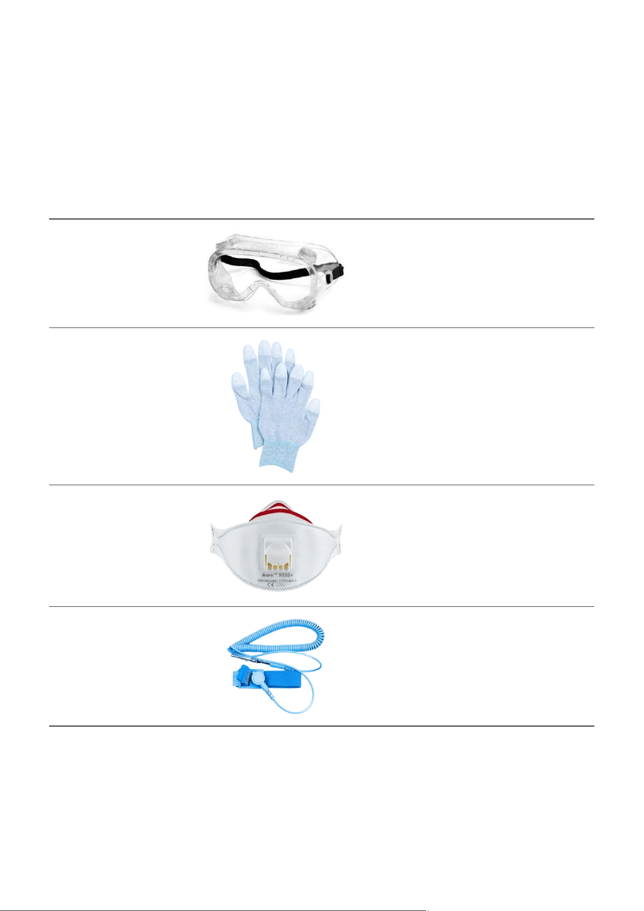
Tools for Disassembly and Assembly
When repairing devices, you absolutely must wear protective equipment for your safety.
Tool & Part Code Image Description
Safety Goggles
Prevents accidents during repair
(protective equipment)
Safety Gloves (ESD
safe, cut-resistant)
Prevents accidents during repair
(protective equipment)
Safety Mask
Prevents accidents during repair
(protective equipment)
Anti-static Wrist
Strap
Prevents electrostatic damage
(recommended)
Disassembly and Assembly
53
Tool & Part Code Image Description
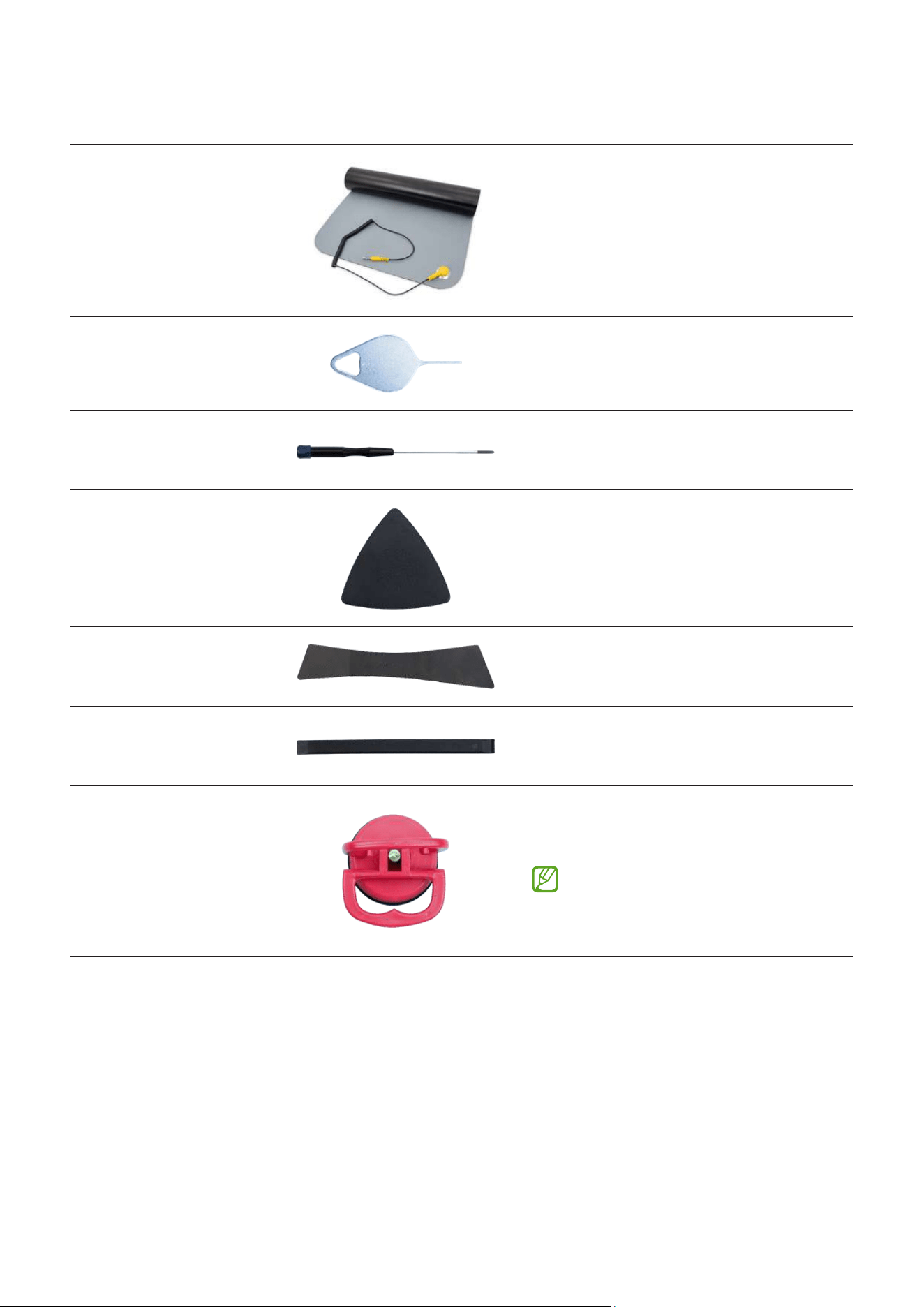
ESD Safe Mat
Prevents electrostatic damage
(recommended)
Ejection Pin
Pin for ejecting the SIM card tray
Cross-head
Screwdriver
Tool for screwing in cross-head
screws
Opening Pick
Tool for disassembling the screen
and other parts
Opening Tool (L)
Tool for disassembling the screen
Opening Tool
Tool for disassembling the
connector and other parts
Suction Cup (L)
Tool for disassembling the screen
and other parts
When removing the screen
of Galaxy Tab S10 Ultra, you
need a large size suction cup.
Disassembly and Assembly
54
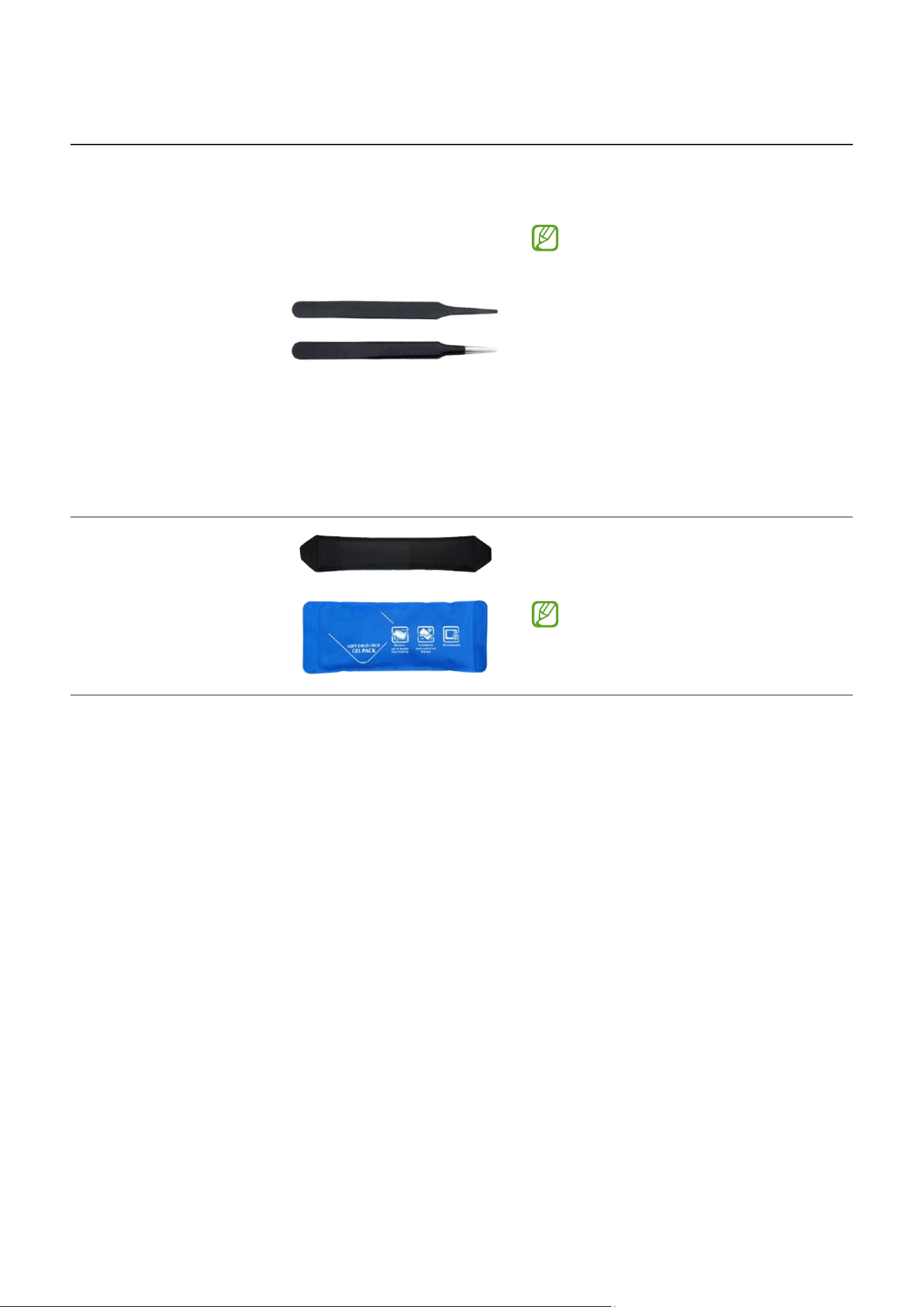
Tool & Part Code Image Description
ESD Safe Tweezers
and Round Tip
Metal Tweezers
Tool for handling connectors,
cables, and other parts
•
Because it is possible
to damage parts or
components when using
sharp tweezers, use
tweezers made with plastic
or rubber material.
•
When removing a vibrator
motor, it is required to
use the round tip metal
tweezers.
Heating Bag
Tool for disassembling the screen
and other parts
When removing the screen
of Galaxy Tab S10 Ultra, you
need the 2 heating bags.
Disassembly and Assembly
55
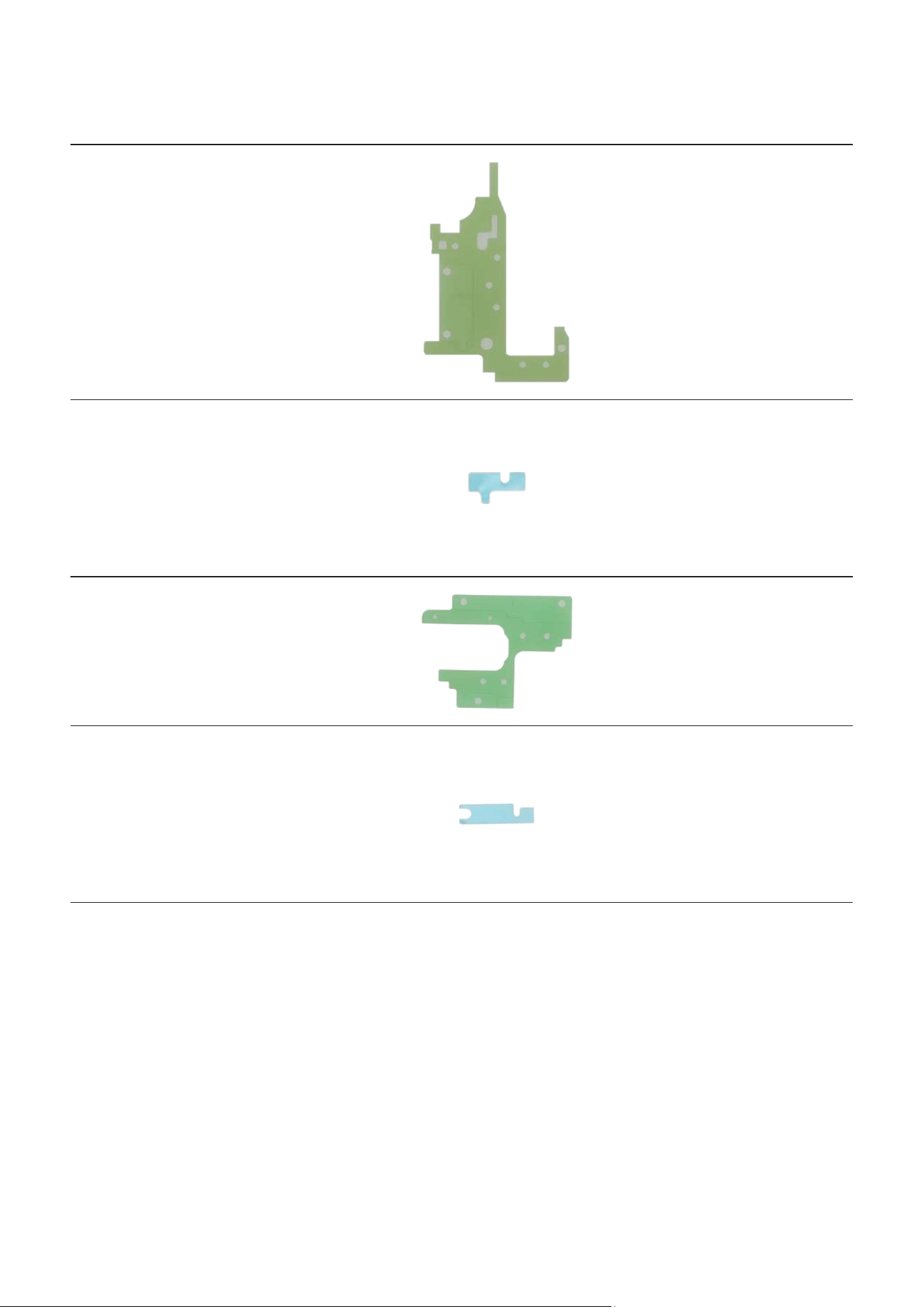
Fasteners (Adhesives and Materials) for Assembly
The fasteners composition may vary depending on the repair parts, country, region, or
carrier.
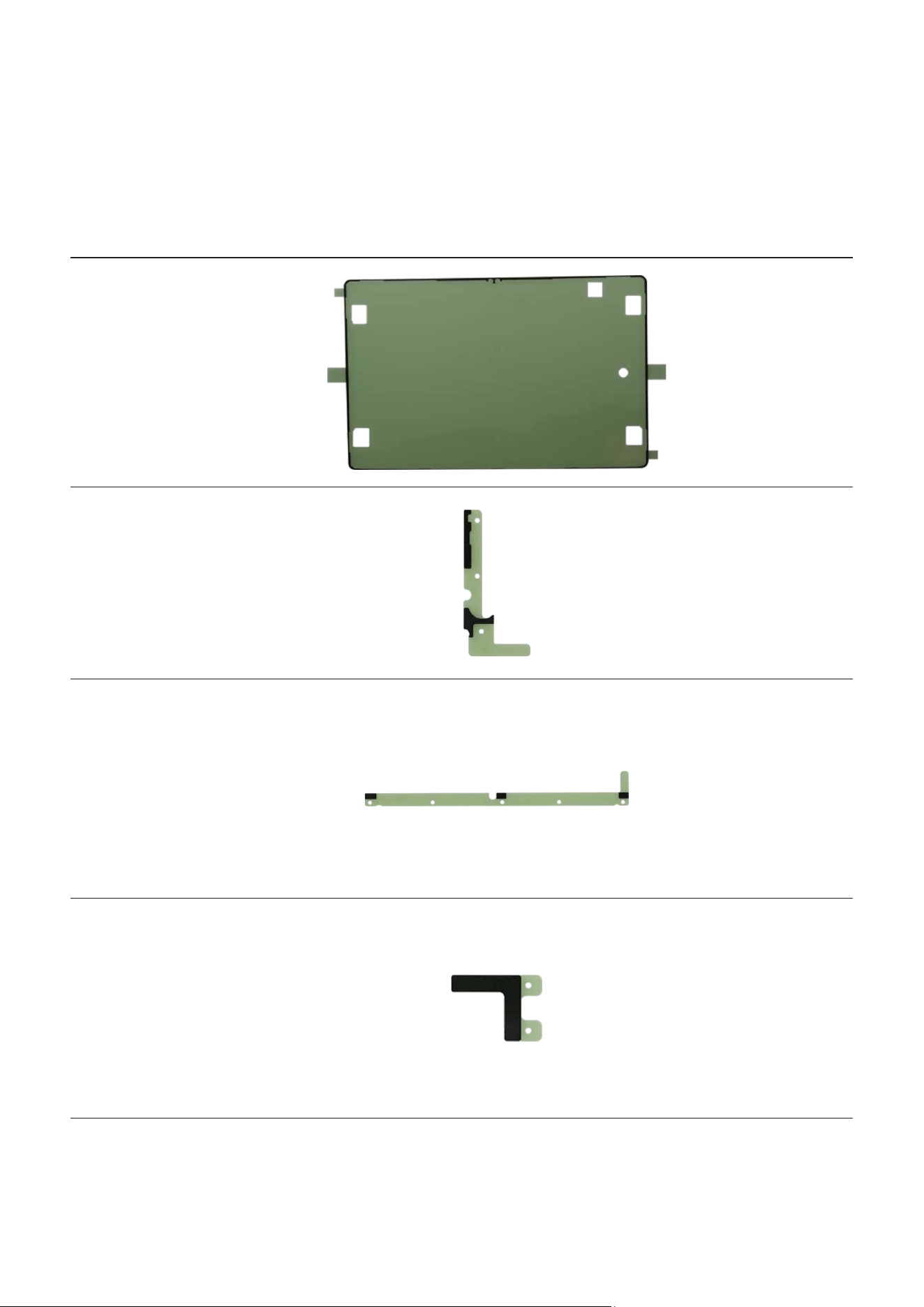
Item Quantity Image Description
Screen
Adhesive Tape
GH81-23920A
1
Double sided
adhesive tape
for attaching the
screen
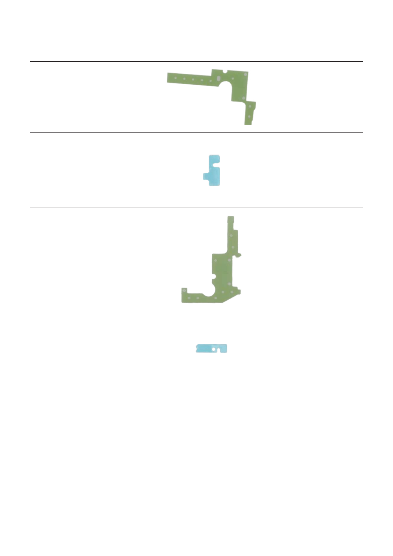
Screen Left
Adhesive Tape
GH81-26674A
1
Double sided
adhesive tape
attached to the
left of the bracket
to assemble the
screen
Screen Bottom
Adhesive Tape
GH81-26673A
1
Double sided
adhesive tape
attached to
the bottom of
the bracket to
assemble the
screen
Screen Right
Adhesive Tape
GH81-26853A
1
Double sided
adhesive tape
attached to
the right of
the bracket to
assemble the
screen
Disassembly and Assembly
56
Item Quantity Image Description
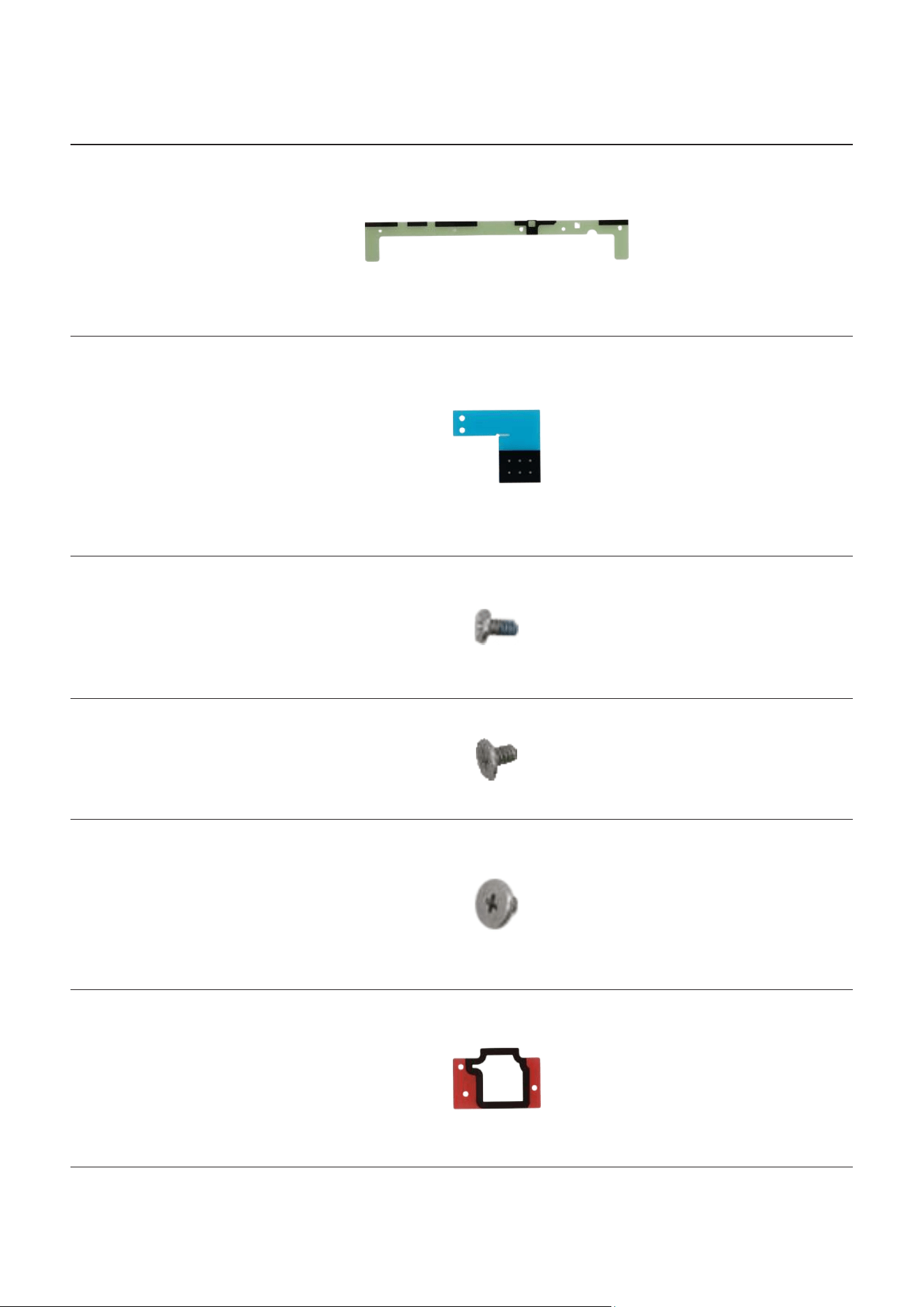
Screen Top
Adhesive Tape
GH81-27034A
1
Double sided
adhesive tape
attached to the
top of the bracket
to assemble the
screen
Screen
Speaker
Adhesive Tape
GH81-26737A
2
Double sided
adhesive tape
attached to the
speaker 2 and
speaker 4 to
assemble the
screen
Screw 3405
6001-003405
46
Screws for the
bracket (35 ea)
Screws for the
speakers (11 ea)
Screw 3463
6001-003463
4
Screws for the
main board (4 ea)
Screw 3443
6001-003443
4
Screws for the
charging port
(3 ea)
Screw for the
Wi-Fi board (1 ea)
SIM Card
Socket
Adhesive Tape
GH81-26565A
1
Double sided
adhesive tape for
attaching the SIM
card socket

Disassembly and Assembly
57
Item Quantity Image Description
SIM Card
Socket FPCB
Adhesive Tape
GH81-23940A
1
Double sided
adhesive tape
for attaching the
FPCB of the SIM
card socket
Vibrator Motor
Adhesive Tape
GH81-21822A
1
Double sided
adhesive tape
for attaching the
vibrator motor
Vibrator Motor
FPCB Adhesive
Tape
GH81-21823A
1
Double sided
adhesive tape
for attaching
the FPCB of the
vibrator motor
Rear Wide
Camera
Adhesive Tape
GH81-24005A
1
Double sided
adhesive tape for
attaching the rear
wide camera
Rear Ultra
Wide Camera
Adhesive Tape
GH81-24006A
1
Double sided
adhesive tape
for attaching the
rear ultra wide
camera
Disassembly and Assembly
58
Item Quantity Image Description
Speaker 1
Adhesive Tape
GH02-26213A
1
Double sided
adhesive tape
for attaching the
speaker 1
Speaker 1
FPCB Adhesive
Tape
GH81-23945A
1
Double sided
adhesive tape
for attaching
the FPCB of the
speaker 1
Speaker 2
Adhesive Tape
GH02-25113A
1
Double sided
adhesive tape
for attaching the
speaker 2
Speaker 2
FPCB Adhesive
tape
GH81-23946A
1
Double sided
adhesive tape
for attaching
the FPCB of the
speaker 2
Disassembly and Assembly
59
Item Quantity Image Description
Speaker 3
Adhesive Tape
GH02-26216A
1
Double sided
adhesive tape
for attaching the
speaker 3
Speaker 3
FPCB Adhesive
Tape
GH81-23944A
1
Double sided
adhesive tape
for attaching
the FPCB of the
speaker 3
Speaker 4
Adhesive Tape
GH02-26215A
1
Double sided
adhesive tape
for attaching the
speaker 4
Speaker 4
FPCB Adhesive
Tape
GH81-23943A
1
Double sided
adhesive tape
for attaching
the FPCB of the
speaker 4

Disassembly and Assembly
60
Disassembly and Reassembly for replacement
The product’s composition may vary depending on the country, region, or carrier.
Before disassembling:
•
Unplug and turn off device before disassembling.
•
If you have an S Pen purchased separately, remove the S Pen.
•
When removing the screen of Galaxy Tab S10 Ultra, you need the 2 heating bags and
a large size suction cup.
•
Wear an anti-static wrist strap and connect it to the grounded ESD safe mat.
Before reassembling:
•
Remove the adhesive tape residues perfectly.
•
Prepare all existing screws of this device and adhesive tapes.
•
Wear an anti-static wrist strap and connect it to the grounded ESD safe mat.
•
Leaving screws inside the device may damage internal components, such as the
battery. When assembling, be extra careful not to leave any unassembled screws
inside the device.
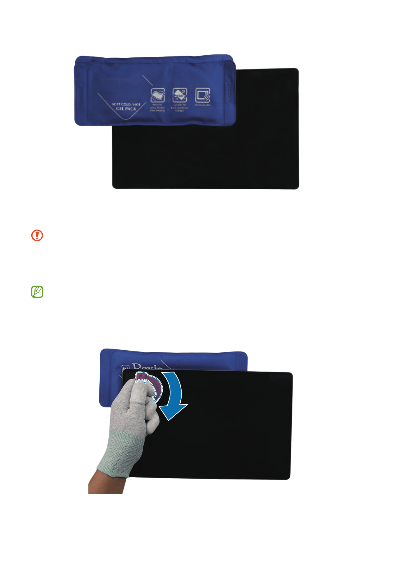
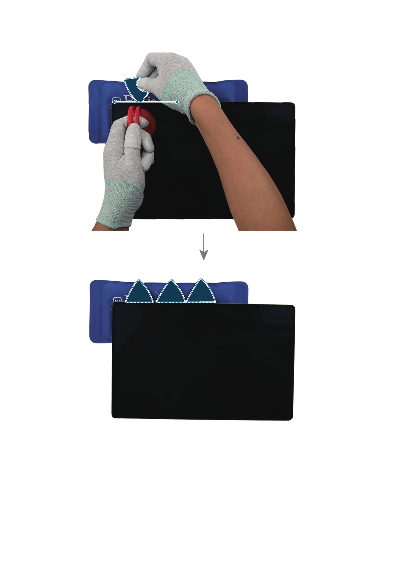
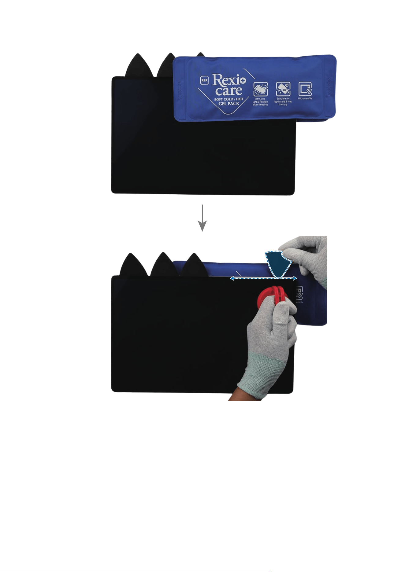
For all cases of broken glass:
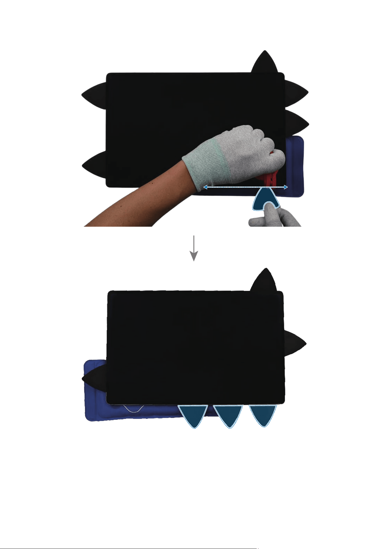
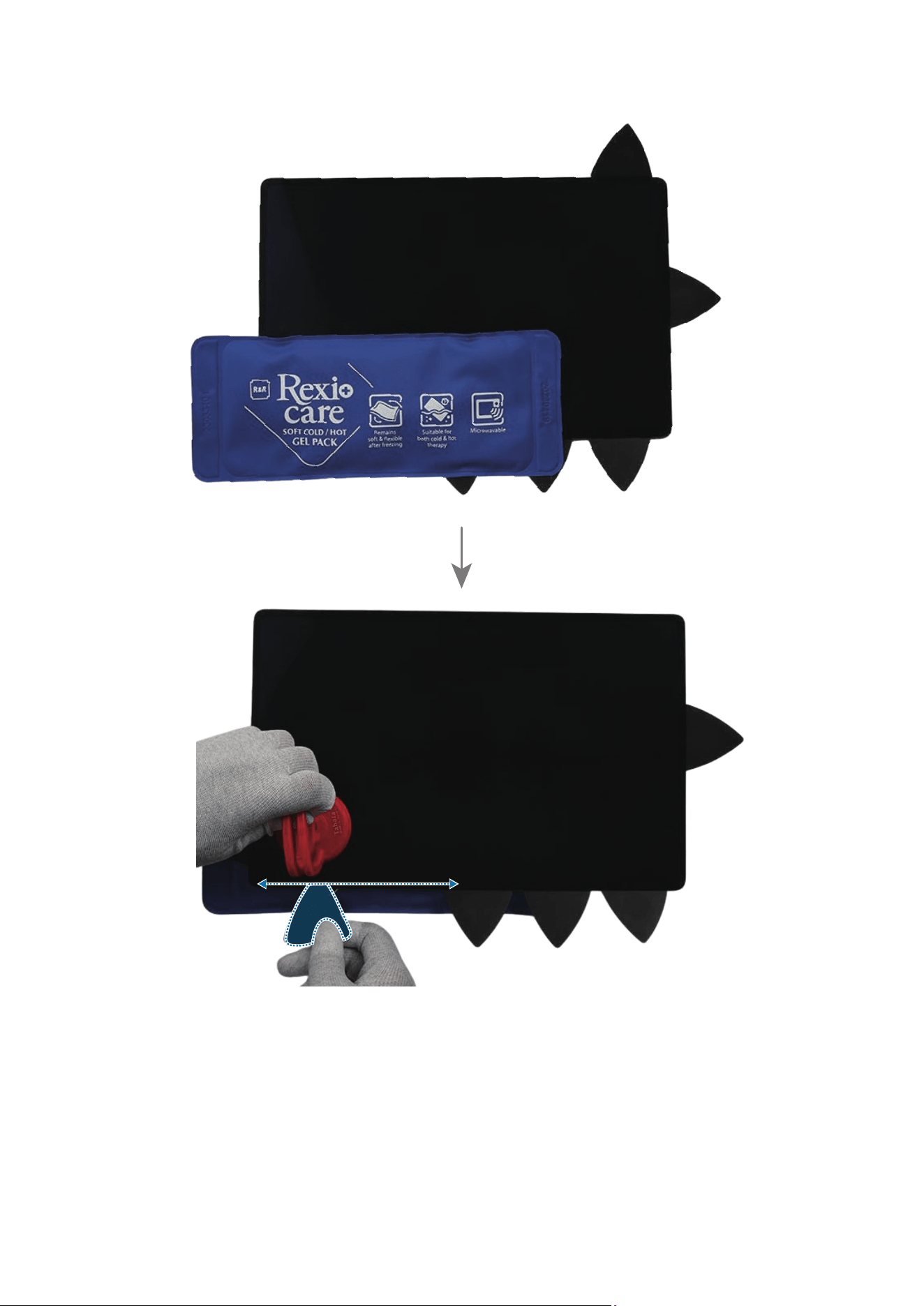
1 Wear safety goggles and cut-resistant gloves.
2 To prevent injuries and scattering caused by broken glass, attach the tape on the
broken glass.
If your device’s glass breaks, be careful not to injure your hands or other body parts
on debris.
3 Press the tape with strong force so that it is strongly attached to the broken glass.
Wait until the adhesive between the tape and the glass is strengthened.
4 Follow the disassembly steps in this guide.
Disassembly and Assembly
61
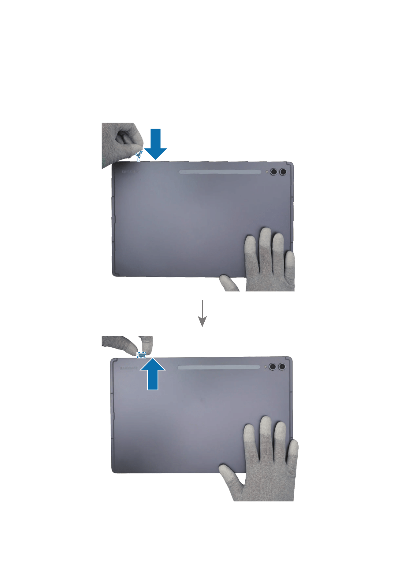
SIM Card Tray
Disassembly
Prepare the device to repair by yourself. Insert the ejection pin into the hole of the SIM
card tray to loosen the tray and pull out the tray gently from the tray slot.
Disassembly and Assembly
62

Disassembly and Assembly
63
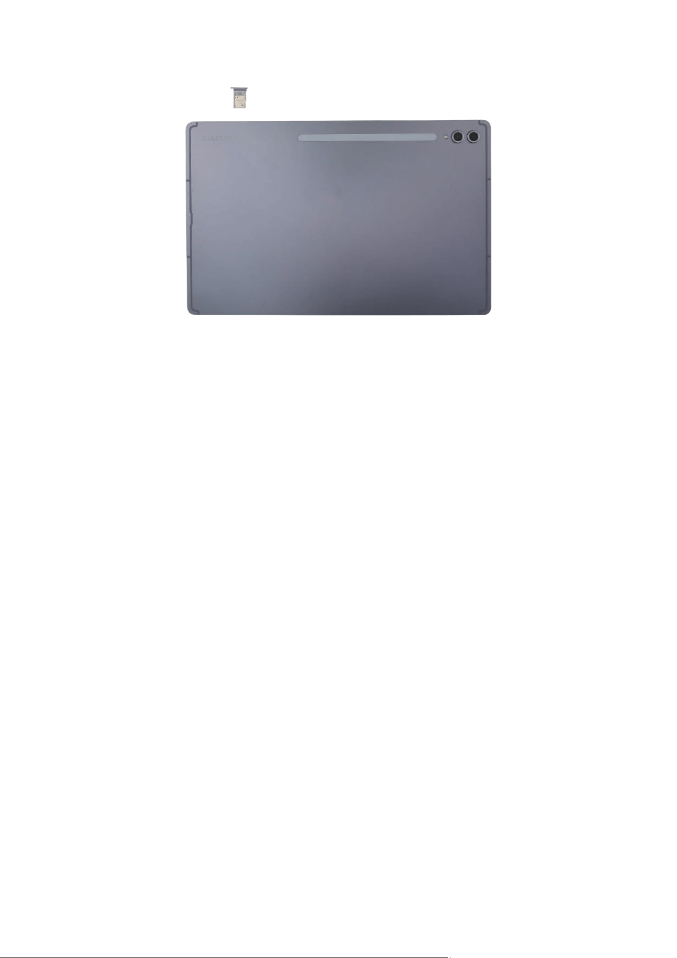
Reassembly
Leaving screws inside the device may damage internal components, such as the
battery. During assembly, be extra careful not to leave any unassembled screws
inside the device.
Insert the SIM card tray back into the slot. Ensure that there are no abnormalities.

Disassembly and Assembly
64
Screen
Disassembly
When removing the screen, ensure that the device is fixed on a flat surface.
When removing the screen of Galaxy Tab S10 Ultra, you need the 2 heating bags
and a large size suction cup.
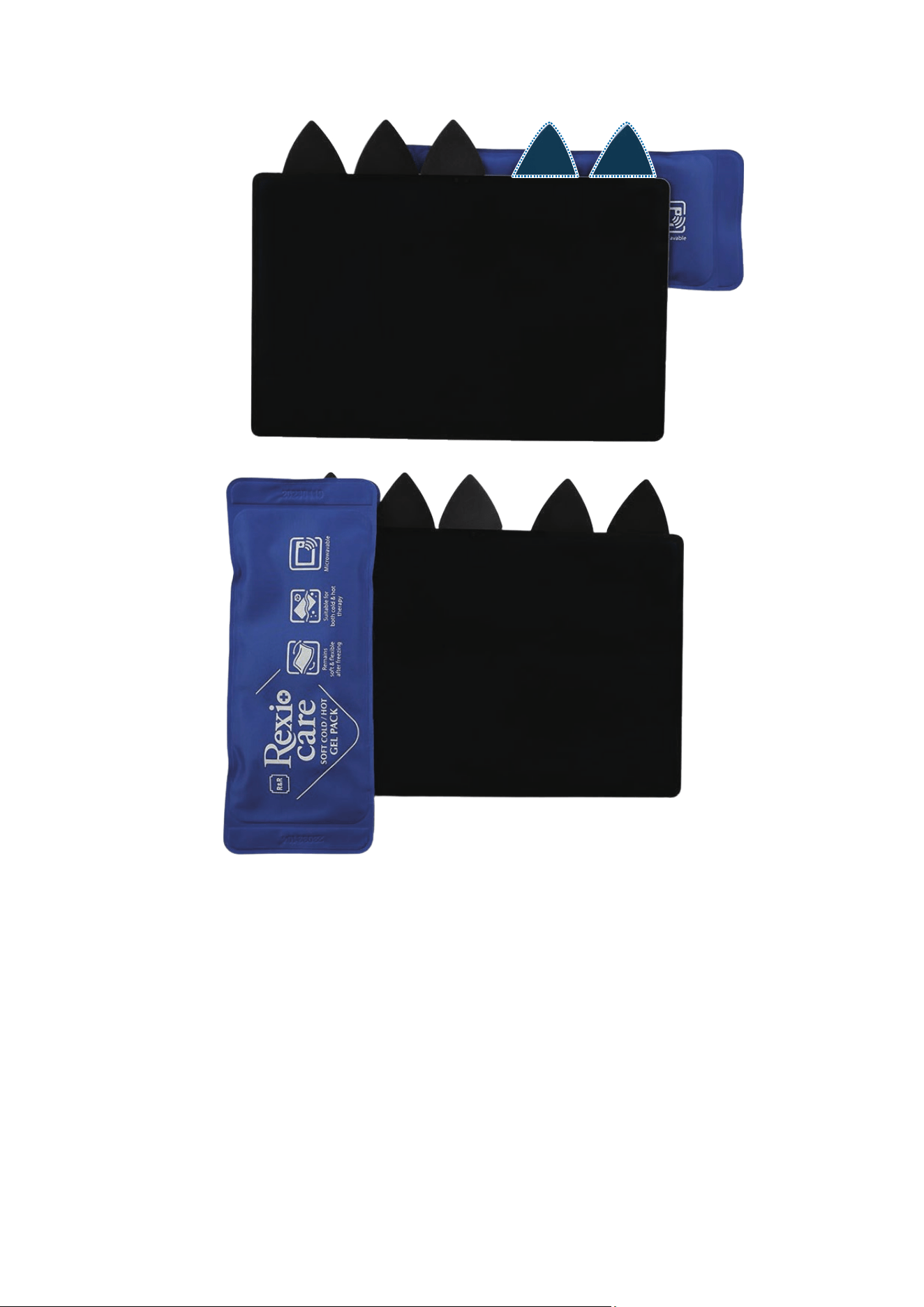
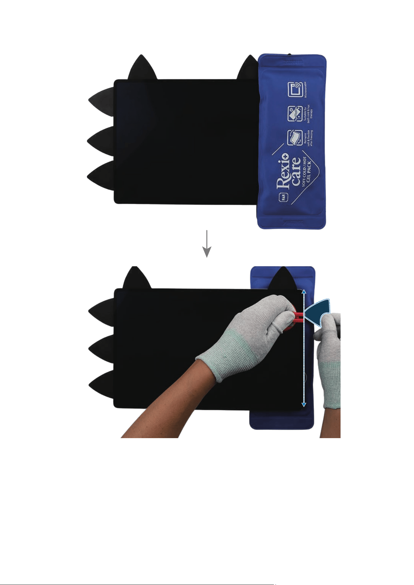
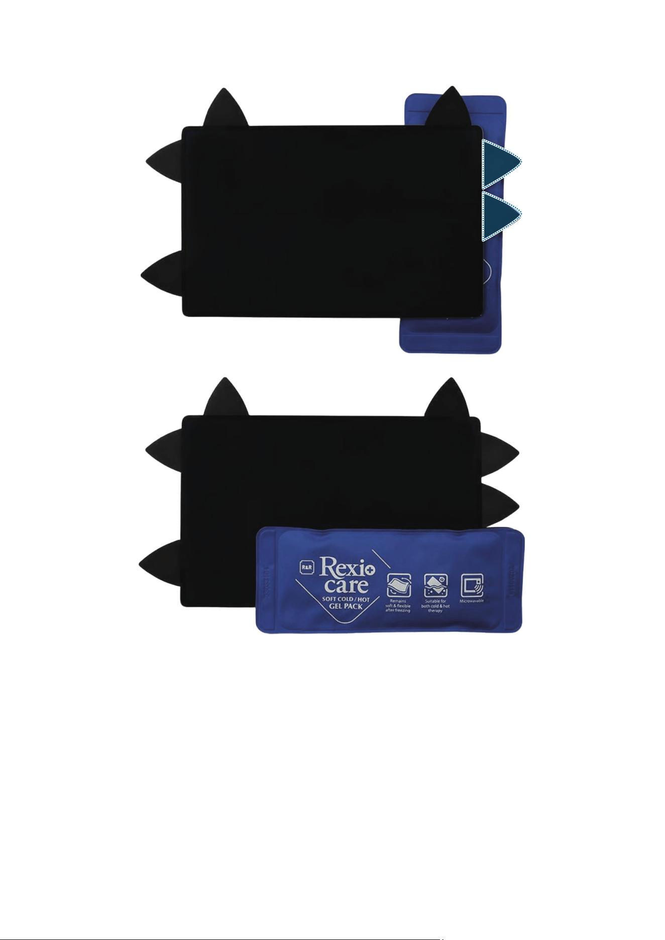
1 Heat the 2 microwaveable heating bags for 90 seconds in a 700 W microwave and
apply each one to the front and back of the top left edge of the device for 4 minutes.
•
It is possible for the device or battery to be damaged by heat.
•
Do not heat the device in a microwave. Doing so could cause an explosion.
•
If your device’s glass breaks, the debris can cause injury to your hands or
other body parts. For your safety, attach the tape on the broken glass before
disassembling the device.
•
Follow the heating bag’s instructions for heating. The recommended time
for heating the 2 microwaveable heating bags is 70 seconds for a 1000 W
microwave and 90 seconds for a 700 W microwave. (Correct temperature for
use: 55-65 ℃.)
•
Be careful not to damage the device through excessive heat. (It is
recommended to disassemble the device in an area with a temperature gauge.)
If the heating bag is cooled down, heat the microwaveable heating bag
additionally, and apply it on the screen to further soften the adhesive. When
reheating, it should be heated no longer than 30 seconds. When reheating the 2
heating bags simultaneously, they should be heated no longer than 50 seconds.
Disassembly and Assembly
65
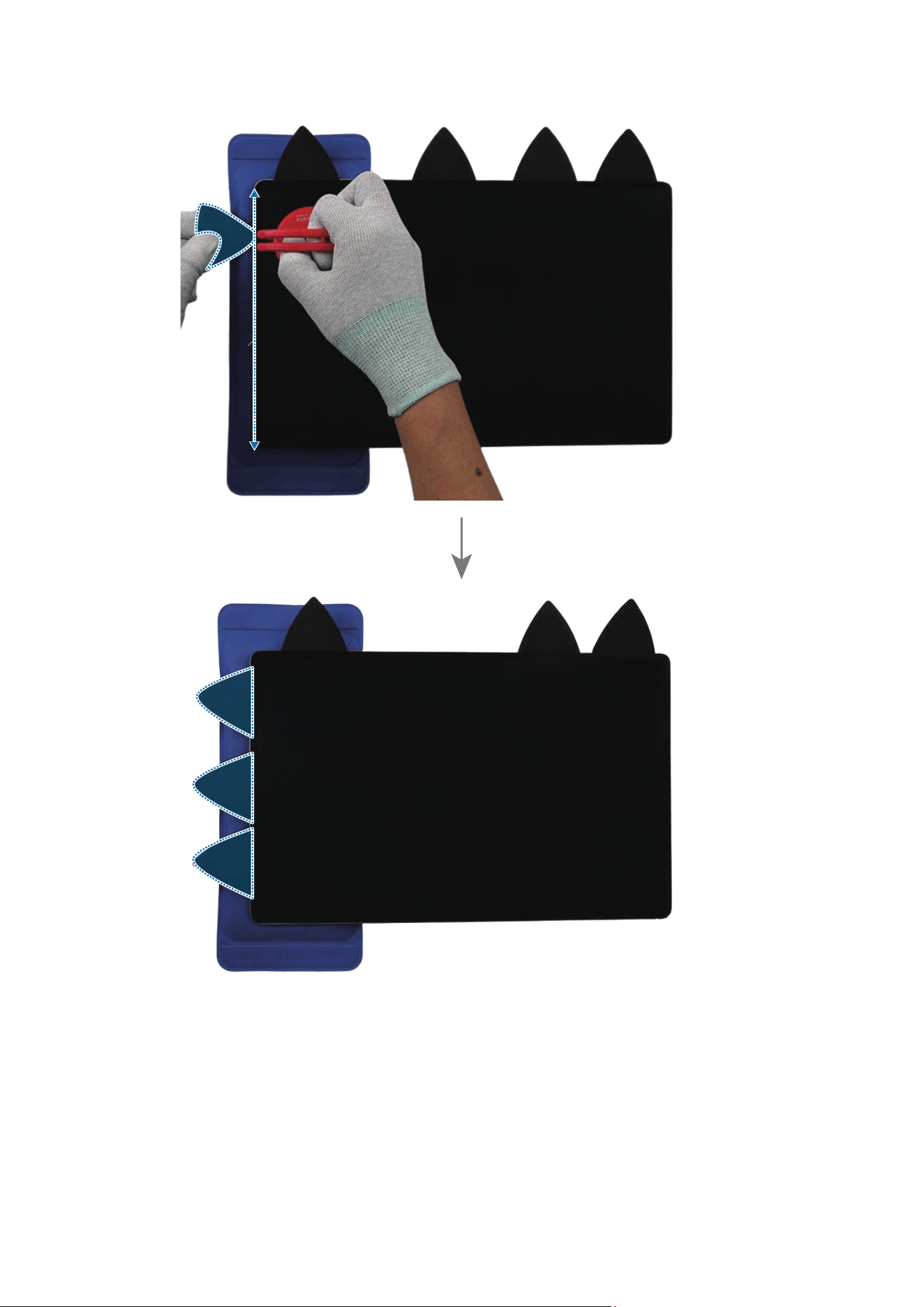
2 While maintaining the heating bag under the back of the device, place the suction
cup (L) on the top left edge of the screen, and lift it upward carefully.
•
As the screen can be damaged by excessive force, be careful not to damage the
screen.
•
Be careful that the suction cup does not adhere to the area where the tape or
sticker is attached.
If you have trouble creating a gap, heat the microwaveable heating bag
additionally, and apply it on the screen to further soften the adhesive. When
reheating, it should be heated no longer than 30 seconds. When reheating the 2
heating bags simultaneously, they should be heated no longer than 50 seconds.
Disassembly and Assembly
66
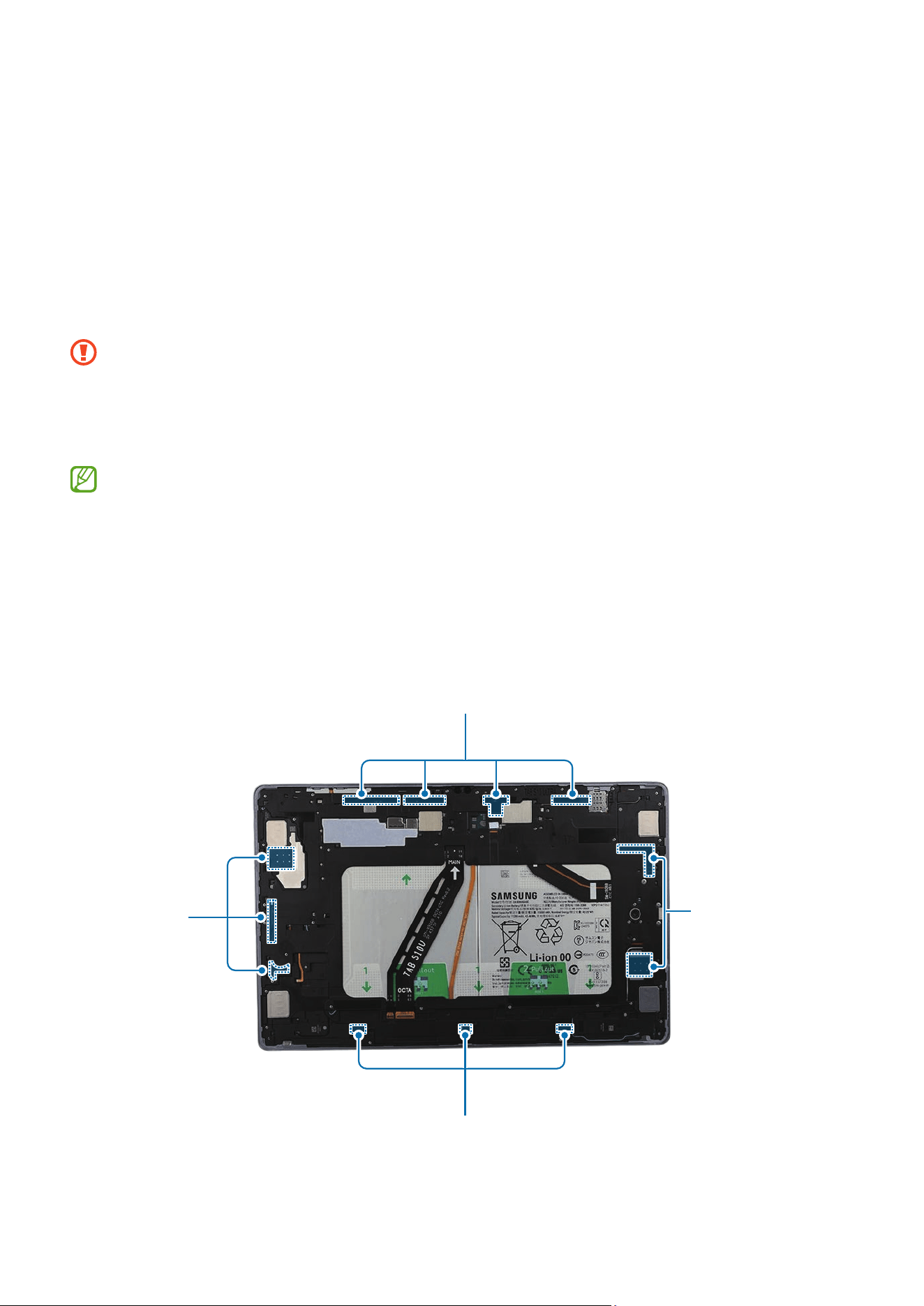
3 While pulling up the suction cup with steady force to create the gap between the
screen and the back cover module, place the opening pick in the gap between the
screen and the back cover module and slide the opening pick back and forth along
the edge to slice through the adhesive. Repeat the same process of applying the
heating bags, placing the suction cup, and the opening pick to separate the screen
adhesive from the top left edge, top right edge, left edge, right edge, bottom right
edge, and bottom left edge. Then, be cautious with the adhesive on the interior side
of the back cover module while gently lifting the screen upwards.
•
As the screen can be damaged by excessive force, be careful not to damage the
screen.
•
As the internal circuitry can be damaged, do not insert the opening pick more
than 2 mm.
•
Make sure to leave the opening pick inserted in the edges to prevent the
adhesive from resealing. It is recommended that a large area of the opening
pick be inserted.
•
If you have trouble creating a gap, heat the microwaveable heating bag
additionally, and apply it on the screen to further soften the adhesive. When
reheating, it should be heated no longer than 30 seconds. When reheating the 2
heating bags simultaneously, they should be heated no longer than 50 seconds.
Adhesive part
Adhesive part
Adhesive
part
Adhesive part
Disassembly and Assembly
67
Disassembly and Assembly
68
Disassembly and Assembly
69
Disassembly and Assembly
70
Disassembly and Assembly
71
Disassembly and Assembly
72
Disassembly and Assembly
73
Disassembly and Assembly
74
Disassembly and Assembly
75
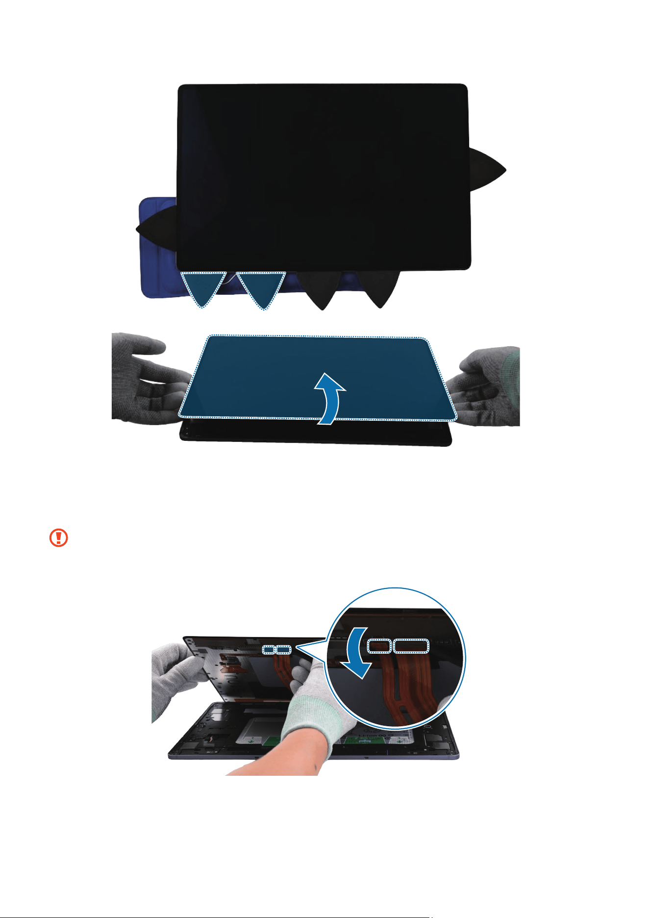
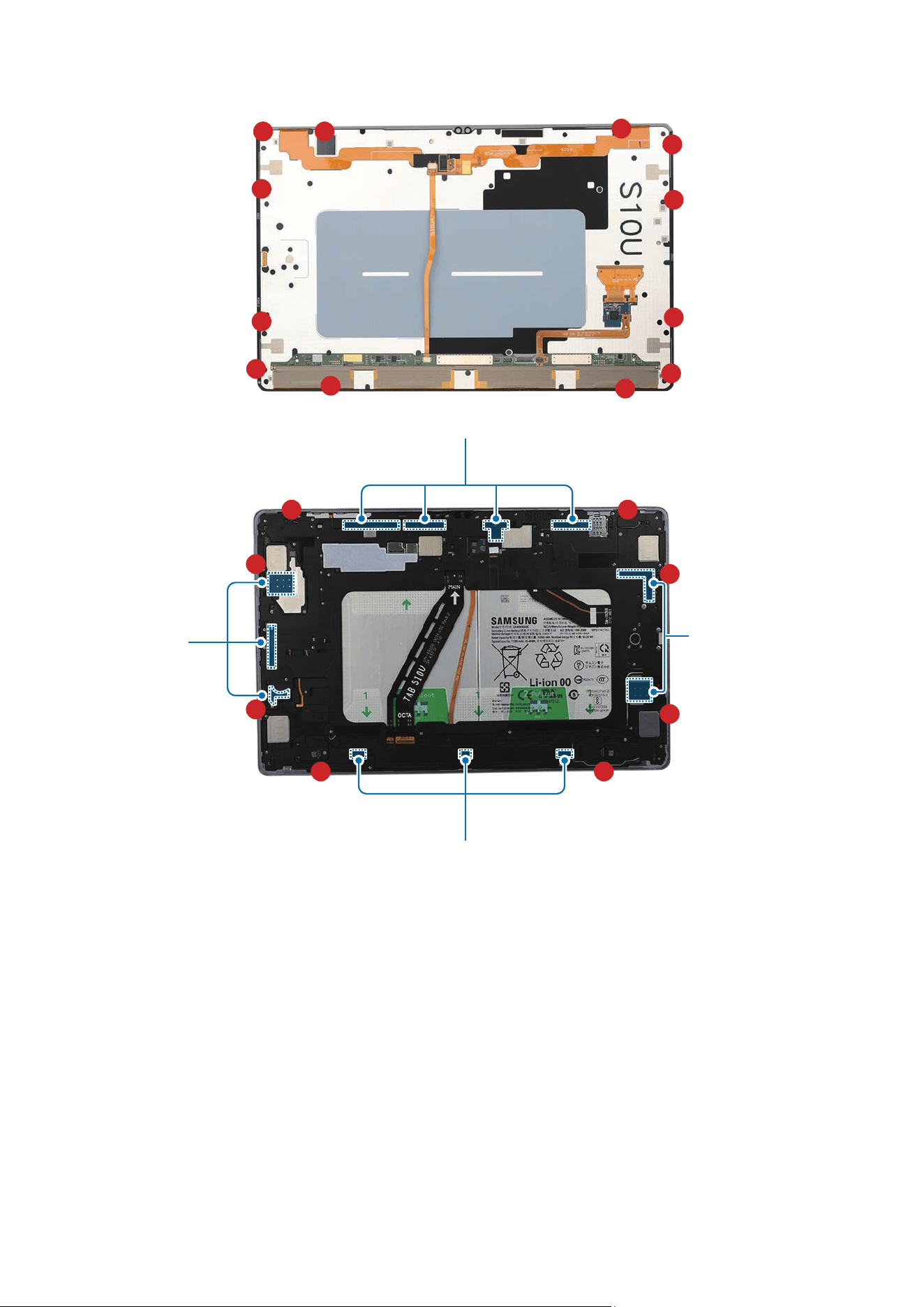
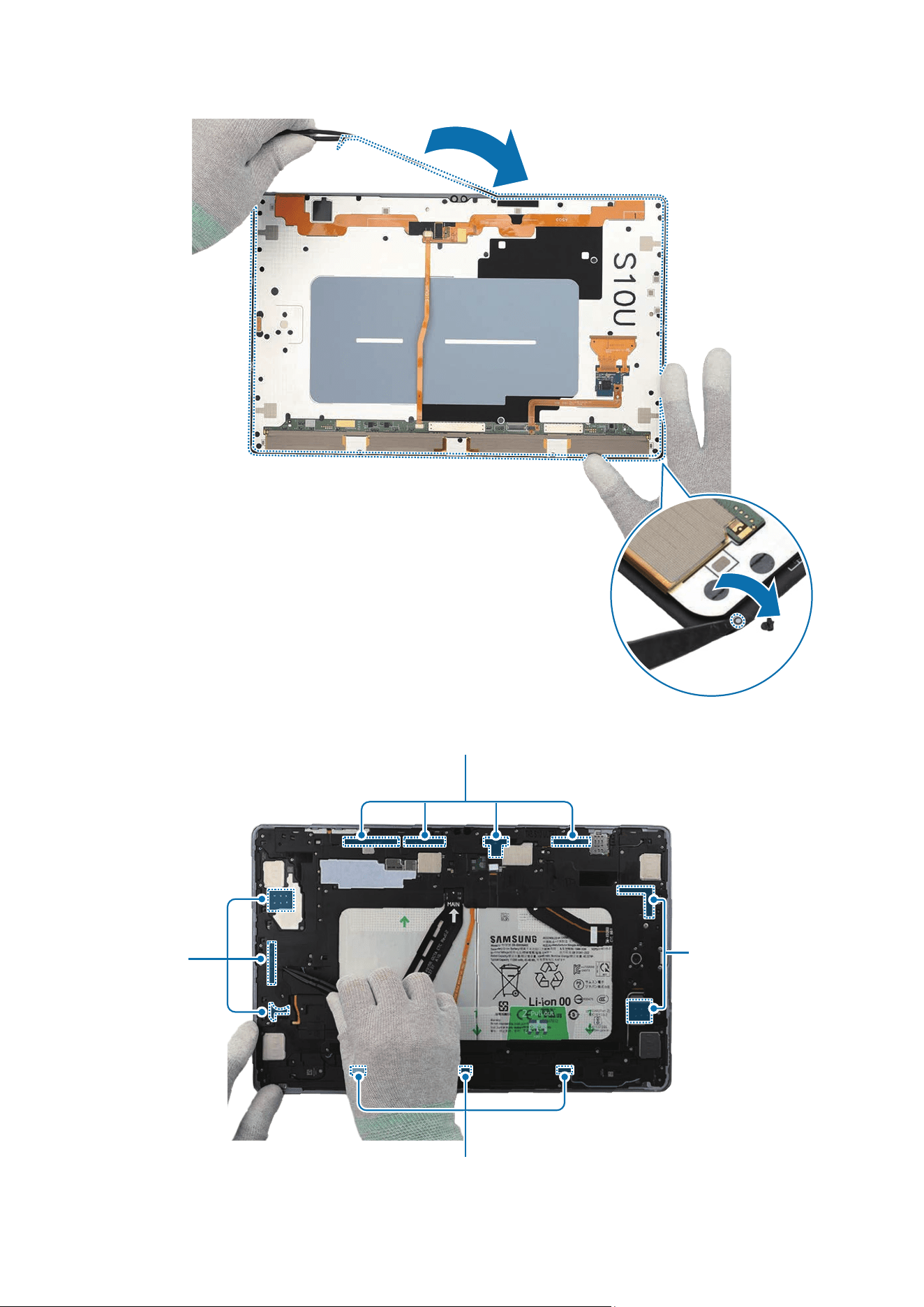
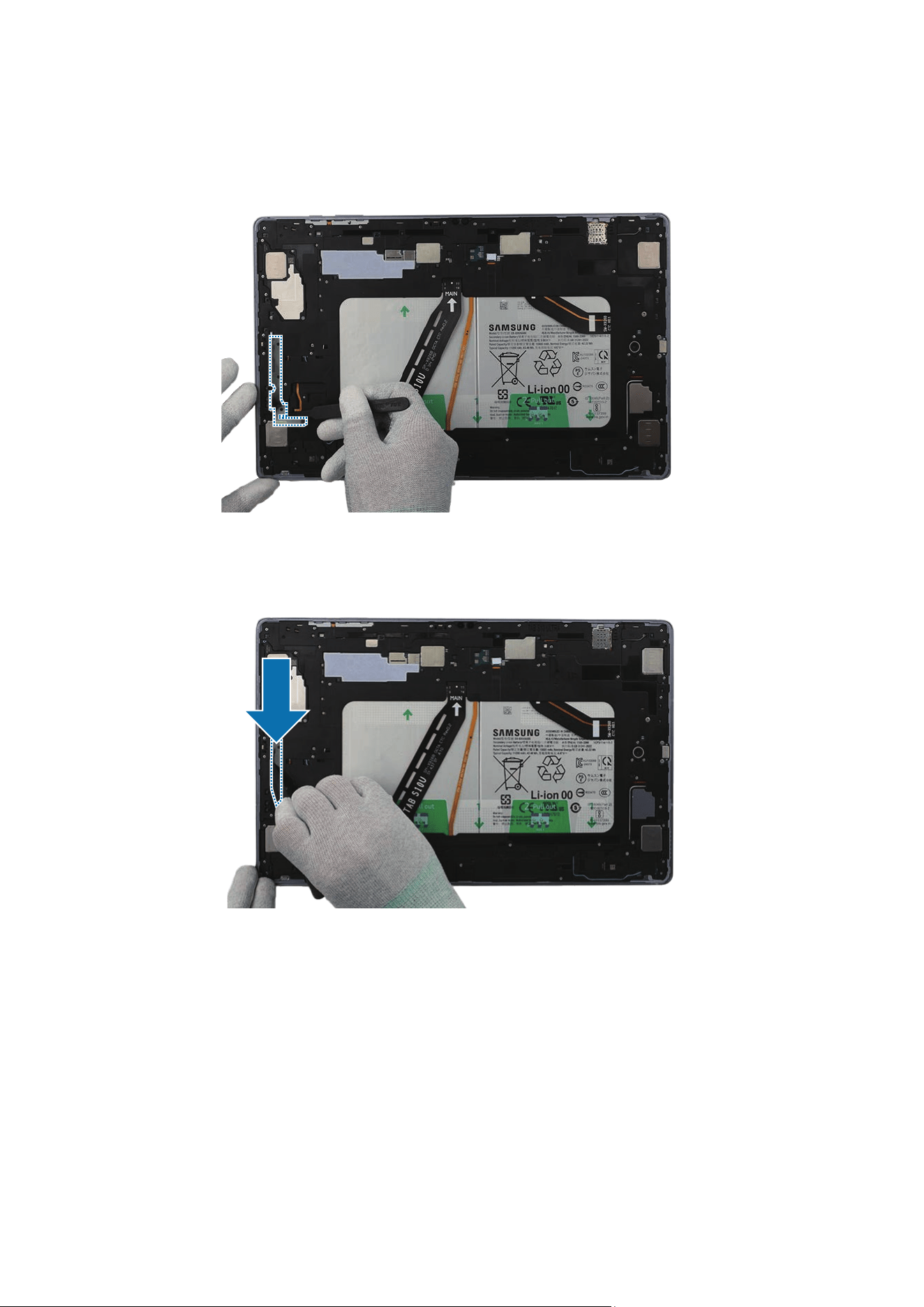
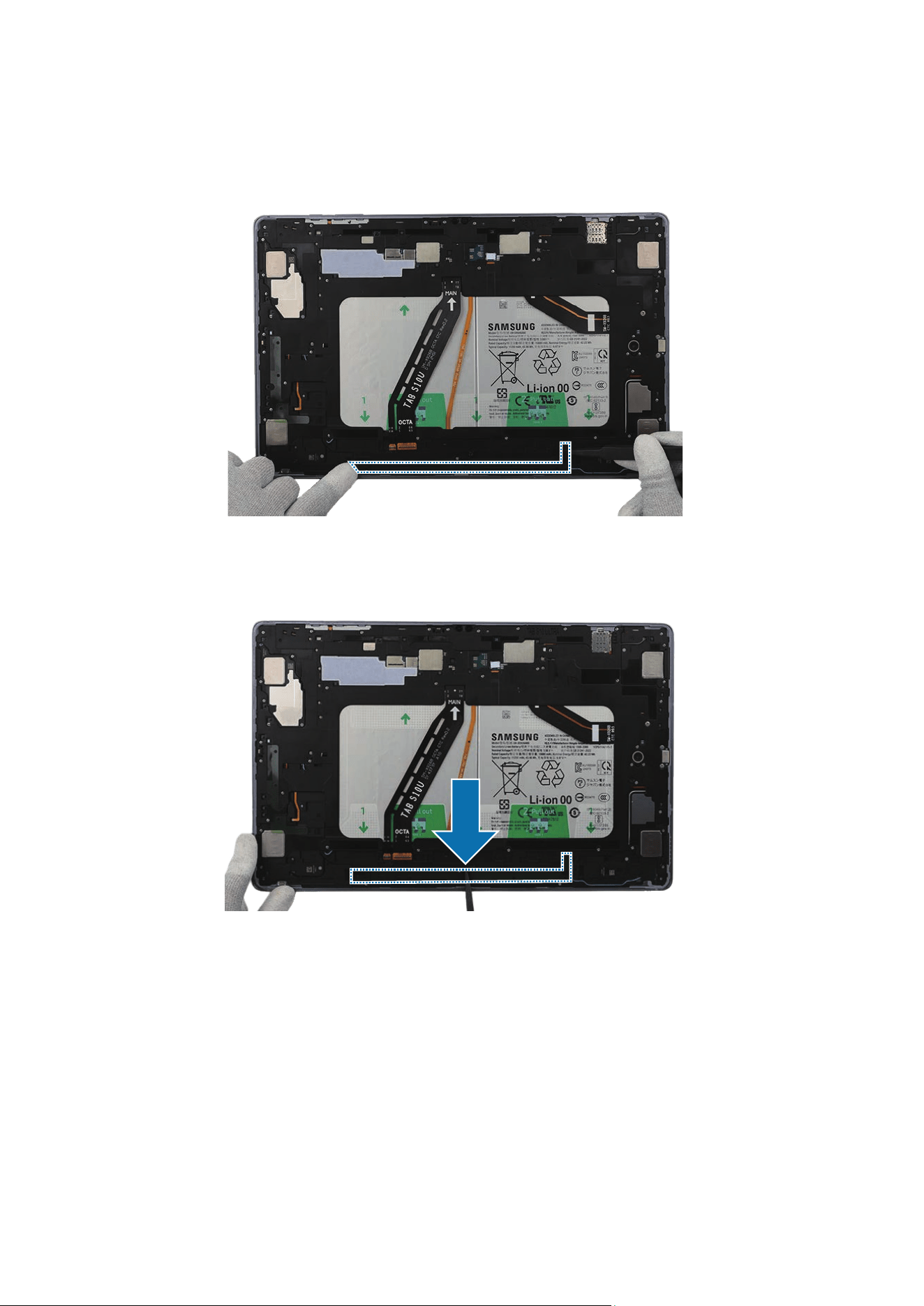
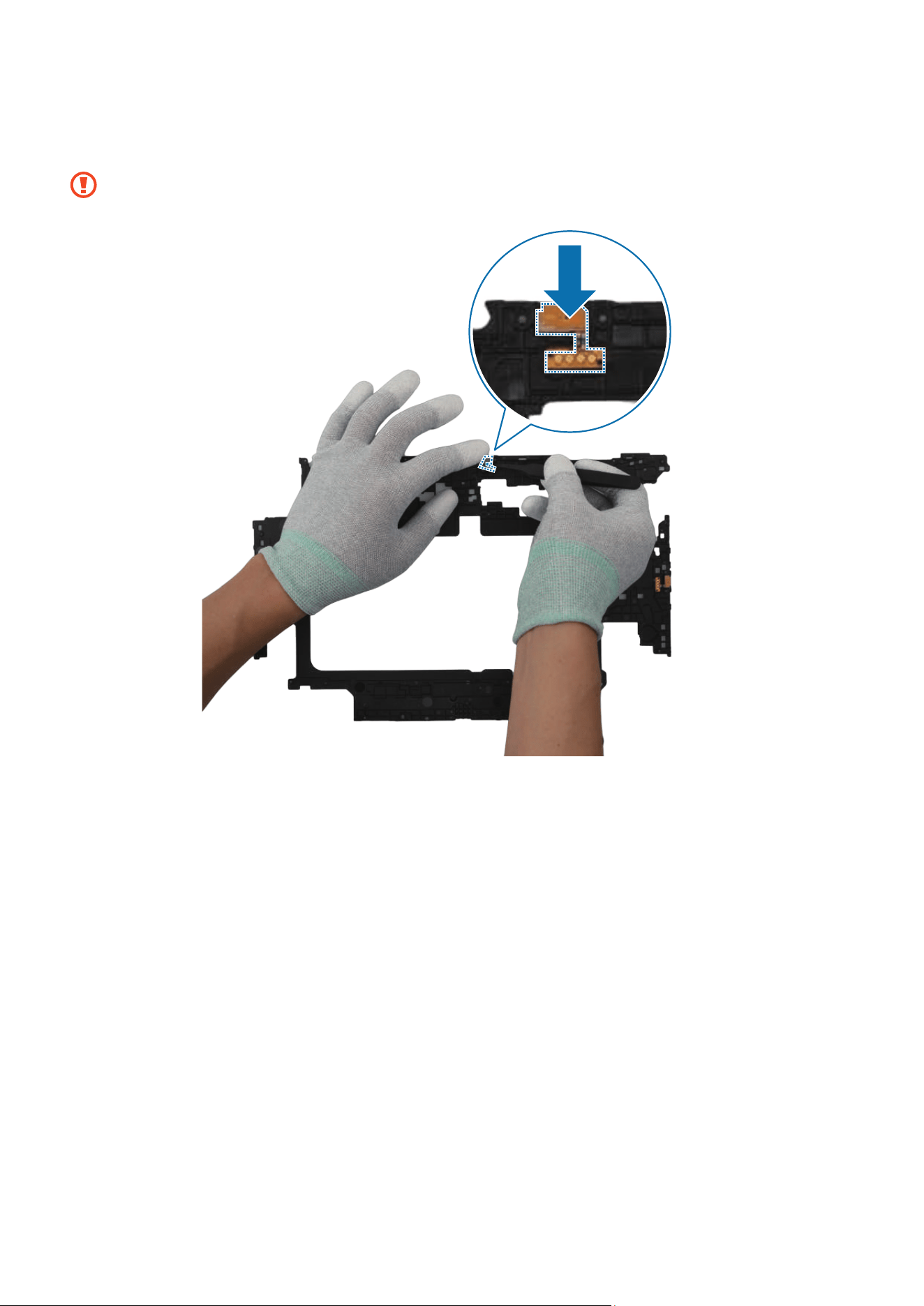
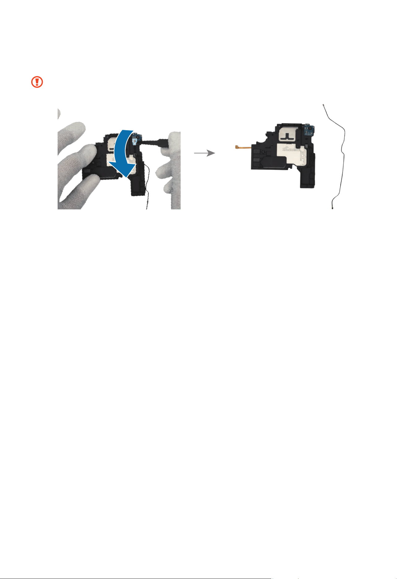
4 Before removing the screen completely, separate the 2 flex cable connectors from
the screen with the tweezers. Lift the screen and separate it from the back cover
module completely.
•
Make sure to separate the connectors before removing the screen completely.
•
Be careful not to damage the cables while removing the connectors.
Disassembly and Assembly
76
Reassembly
Leaving screws inside the device may damage internal components, such as the
battery. When assembling, be extra careful not to leave any unassembled screws
inside the device.
Before attaching the screen, make absolutely sure that there are no screws,
miscellaneous parts, or other foreign objects on the inside of the device (among
the battery, PBA, etc.).
The adhesive tape’s composition may vary depending on the country, region, or
carrier. Check the tape provided and proceed with the appropriate item for each
step.
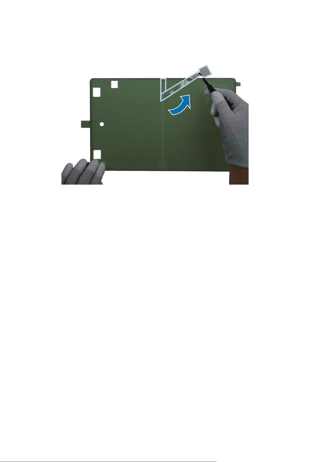
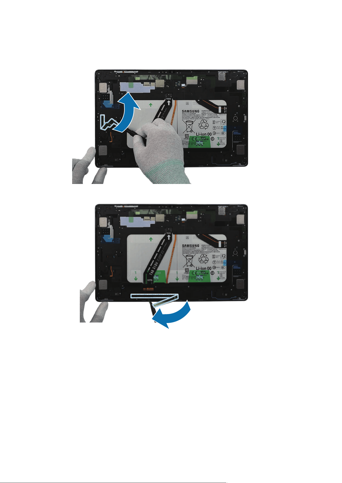
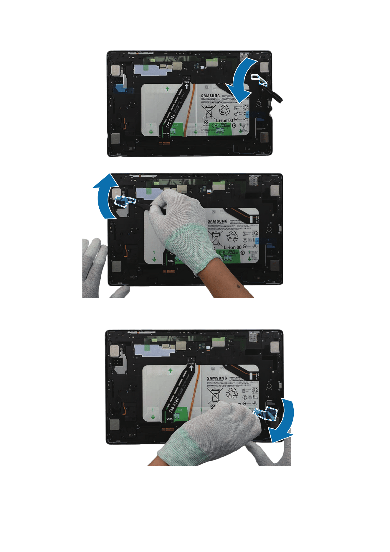
1 Using the tweezers, remove all adhesive tapes on the inside of the screen ( ) and the
back cover module (Adhesive part).
•
Make sure to remove any residual tapes ( ) attached to the inside of the screen
or the back cover module before reassembling the device.
•
Be careful not to damage the near components.
Apply additional heat with a microwaveable heating bag if you are having trouble
separating the adhesive.
Disassembly and Assembly
77
Adhesive part
Adhesive part
Adhesive
part
Adhesive part
Disassembly and Assembly
78
Adhesive part
Adhesive part
Adhesive
part
Adhesive part
Disassembly and Assembly
79
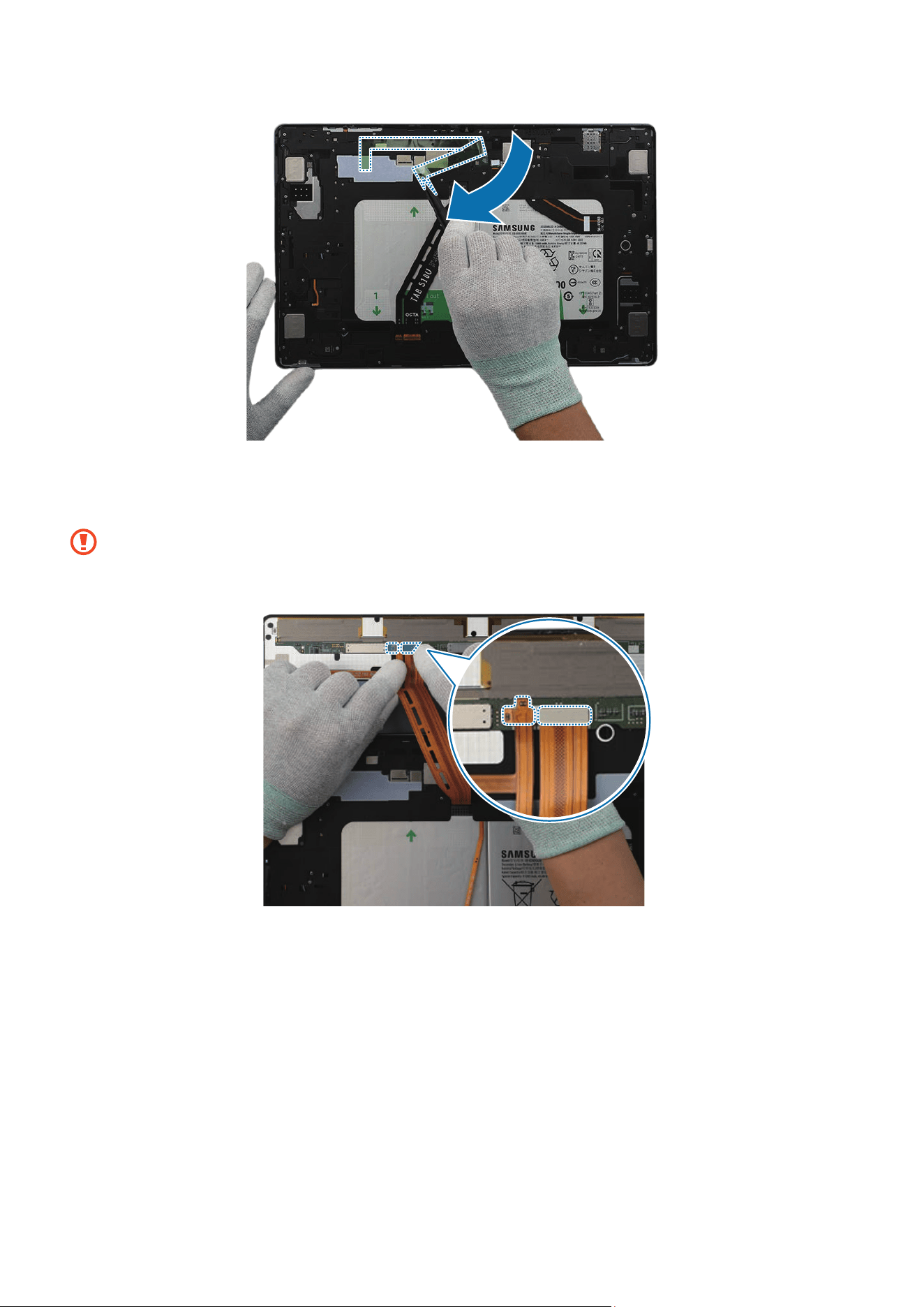
2 Using the tweezers, remove the transparent film from the screen left adhesive tape.
Align the tape precisely with the form on the left of the back cover module and attach
it.
3 Using the tweezers or your fingers, gently press down on the tape to ensure a secure
fit.
Disassembly and Assembly
80
4 Using the tweezers, remove the transparent film from the screen bottom adhesive
tape. Align the tape precisely with the form on the bottom of the back cover module
and attach it.
5 Using the tweezers or your fingers, gently press down on the tape to ensure a secure
fit.
Disassembly and Assembly
81
6 Using the tweezers, remove the transparent film from the screen right adhesive tape.
Align the tape precisely with the form on the right of the back cover module and
attach it.
7 Using the tweezers or your fingers, gently press down on the tape to ensure a secure
fit.
Disassembly and Assembly
82
8 Using the tweezers, remove the transparent film from the screen speaker adhesive
tape. Align the tape precisely with the form on the speaker 2 and attach it.
9 Using the tweezers or your fingers, gently press down on the tape to ensure a secure
fit.
Disassembly and Assembly
83
10
Using the tweezers, remove the transparent film from the screen speaker adhesive
tape. Align the tape precisely with the form on the speaker 4 and attach it.
11
Using the tweezers or your fingers, gently press down on the tape to ensure a secure
fit.
Disassembly and Assembly
84
12
Using the tweezers, remove the transparent film from the screen top adhesive tape.
Align the tape precisely with the form on the top of the back cover module and attach
it.
13
Using the tweezers or your fingers, gently press down on the tape to ensure a secure
fit.
Disassembly and Assembly
85
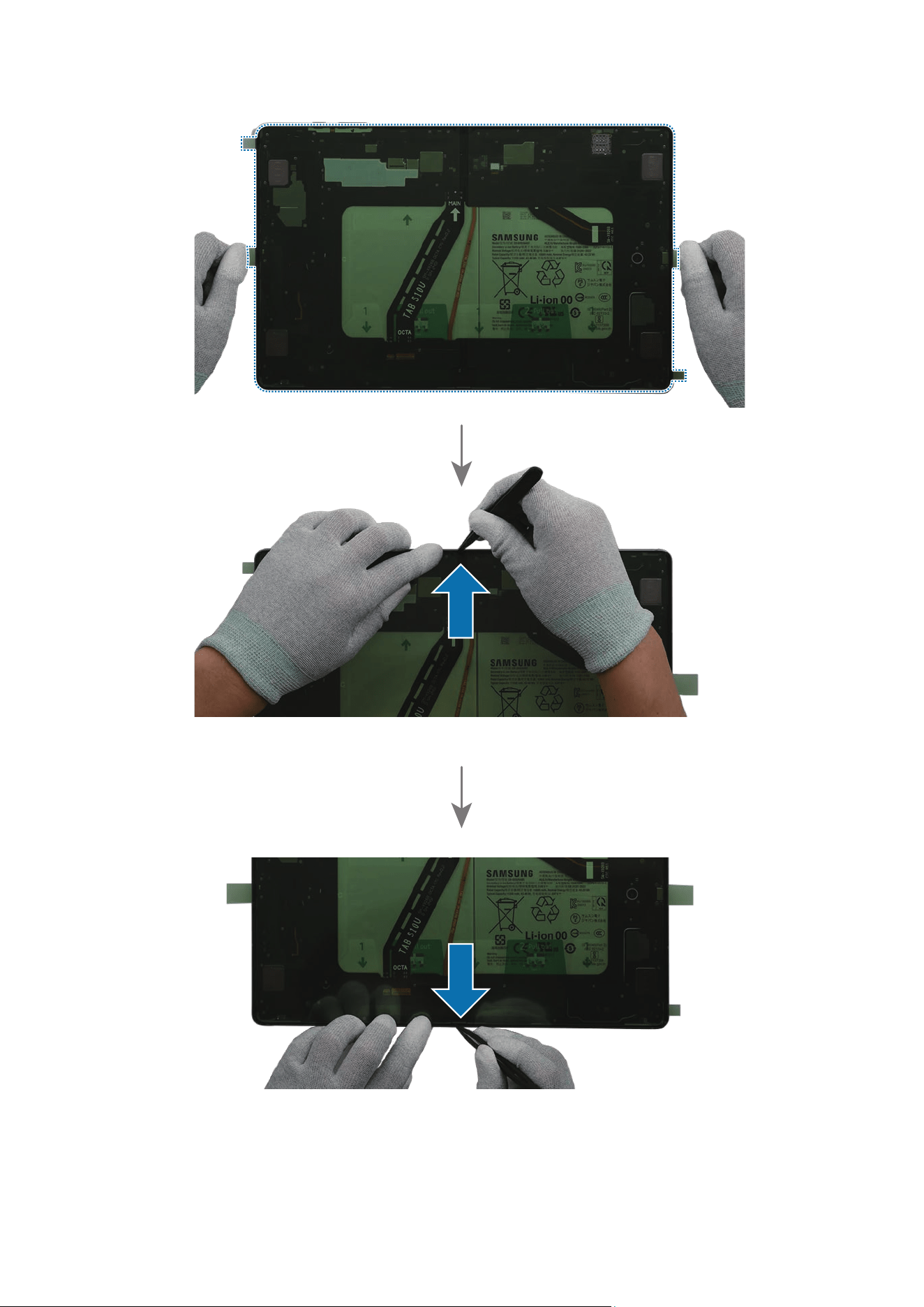
14
Using the tweezers, remove the inner vertical transparent film on the centre of the
new screen adhesive tape.
15
Using your fingers, align the adhesive tape precisely on the back cover module and
attach it. Using the tweezers and your fingers, gently press down the upper and lower
middle of the adhesive tape to ensure a secure fit.
Disassembly and Assembly
86
Disassembly and Assembly
87
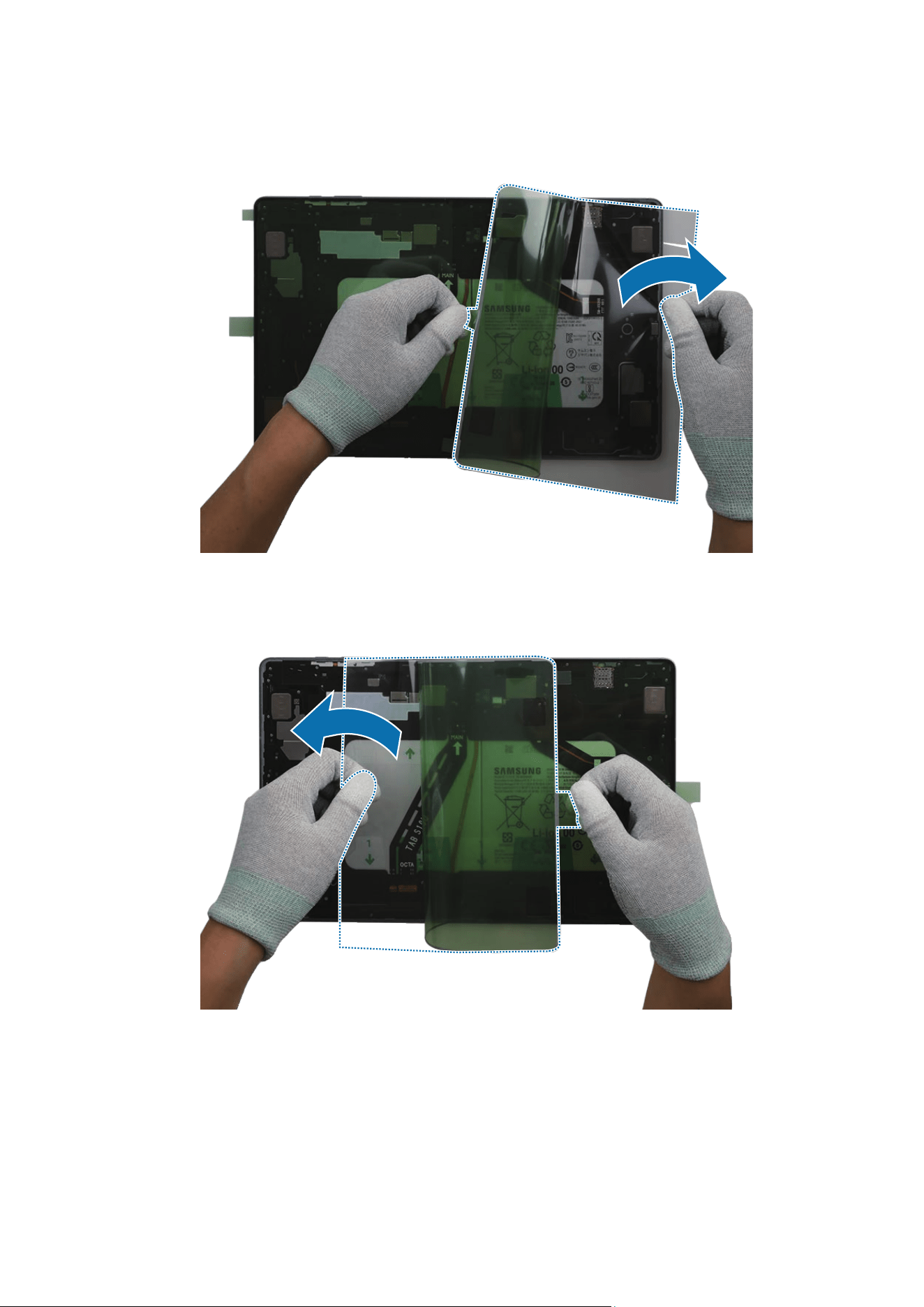
16
Using your fingers, lift the right side of the adhesive tape and remove the inner
transparent film from the centre of the inside.
17
Using your fingers, lift the left side of the adhesive tape and remove the inner
transparent film from the centre of the inside.
Disassembly and Assembly
88
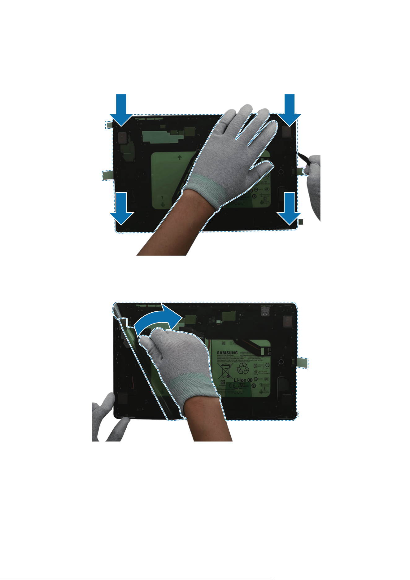
18
Using the tweezers, align the adhesive tape precisely on the back cover module and
attach it. Using the tweezers and your fingers, gently press down on the edges to
ensure a secure fit.
19
While holding the handle of the release film, remove the green transparent film from
the adhesive tape.
Disassembly and Assembly
89
20
Using the tweezers or your fingers, remove all remaining release films on the back
cover module.
Disassembly and Assembly
90
Disassembly and Assembly
91
21
Leave the inside of the screen visible and connect the 2 flex cable connectors
between the screen and the back cover module using your fingers.
•
Be careful not to damage the cables and the connectors.
•
Be careful not to damage the screen.
Disassembly and Assembly
92
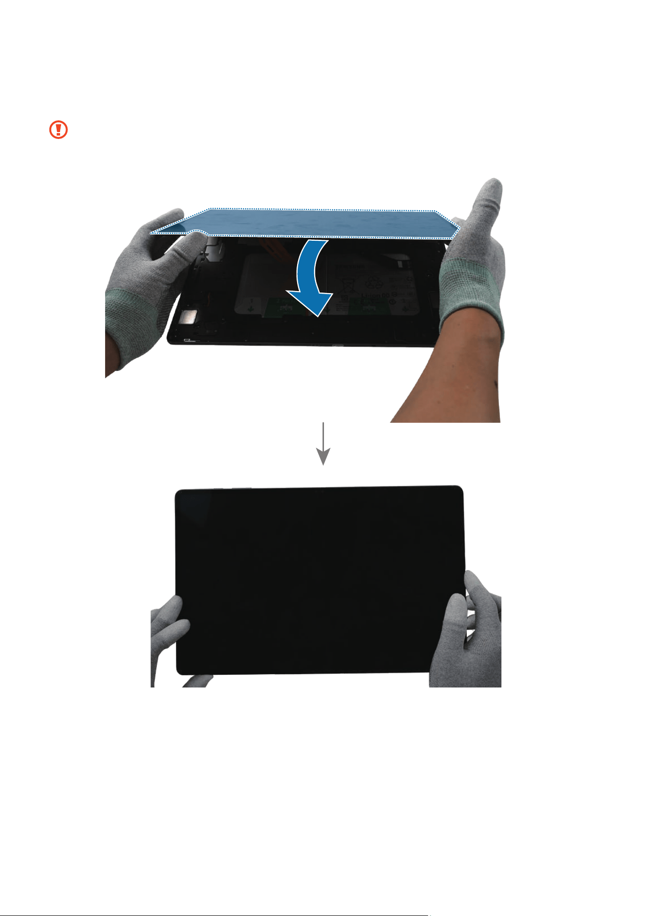
22
Turn the screen slowly over back to its original state and attach it to the back cover
module.
•
Be careful not to damage the cables and the connectors.
•
Be careful not to damage the screen.
Disassembly and Assembly
93
23
Press down on the edges of the screen evenly in order to attach the screen perfectly.
If you feel some gap, remove the screen and attach it again. Some foreign
materials can be inside the device.
Disassembly and Assembly
94
Bracket
Disassembly
Remove the Screen first before you begin.
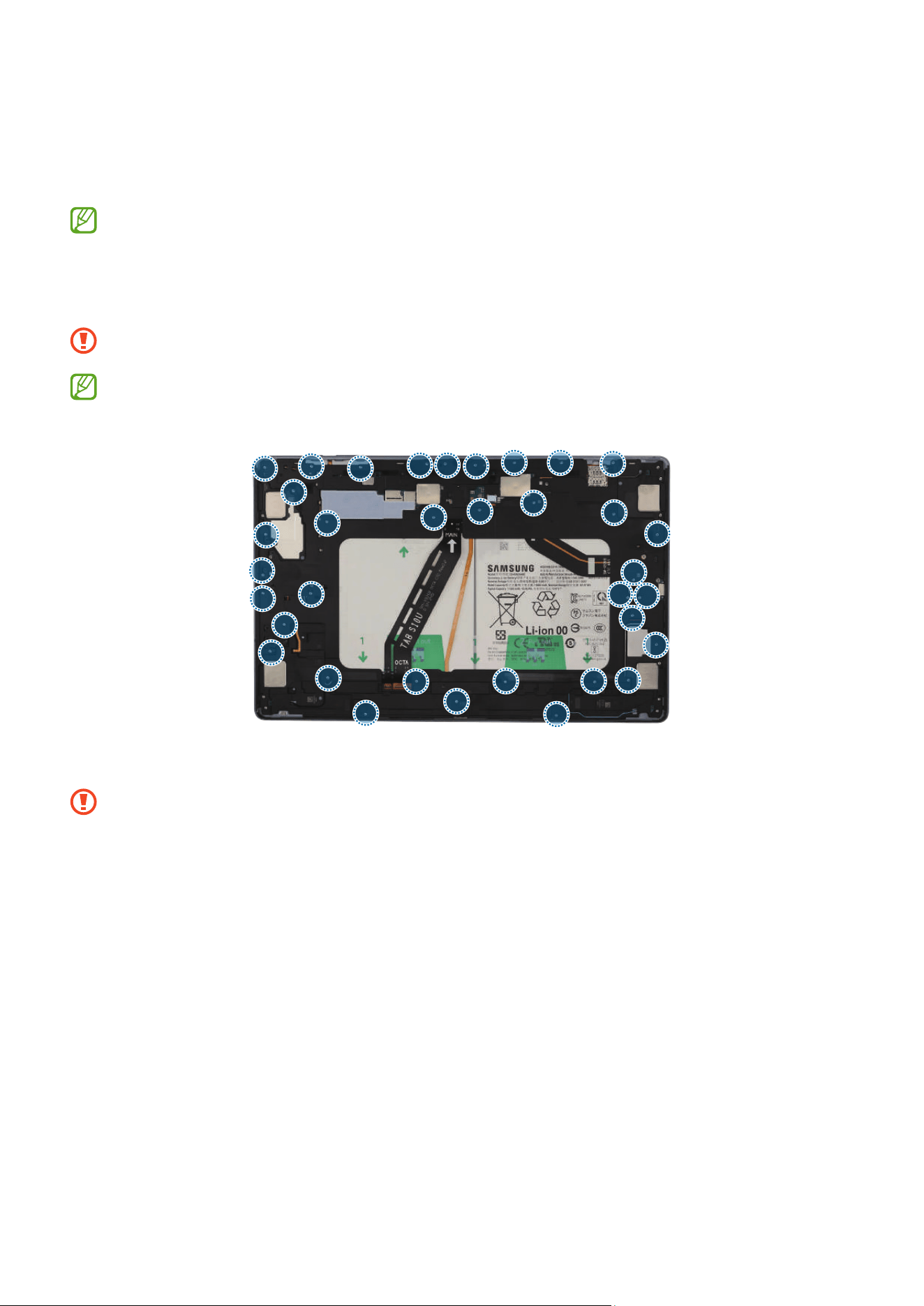
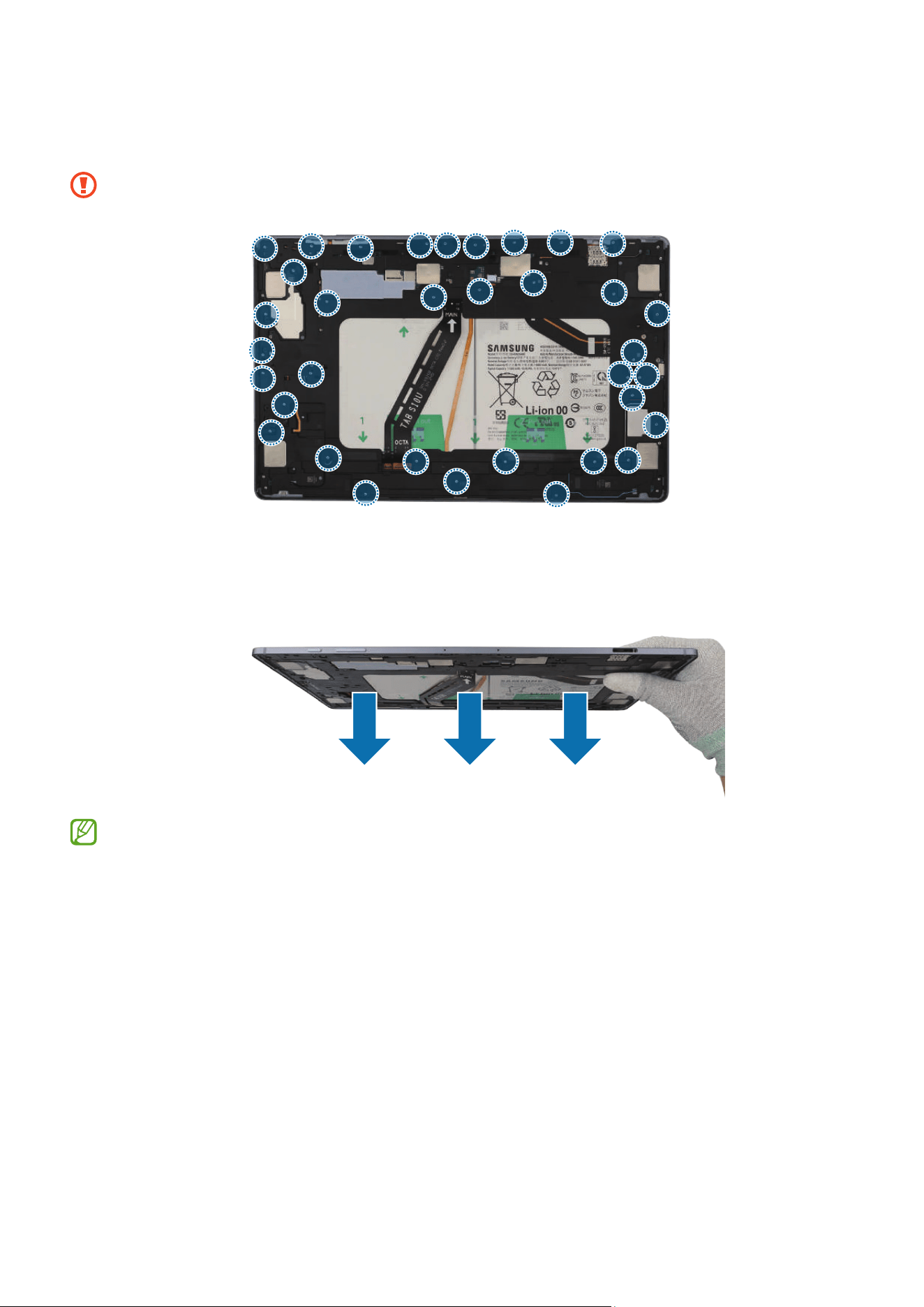
1 Check and remove the screws at the 35 different points on the bracket using a
cross-head screwdriver.
Be careful not to damage the near components.
Check the number of screws that have been removed, and store them carefully to
make sure that no unassembled screws are left inside the device during assembly.
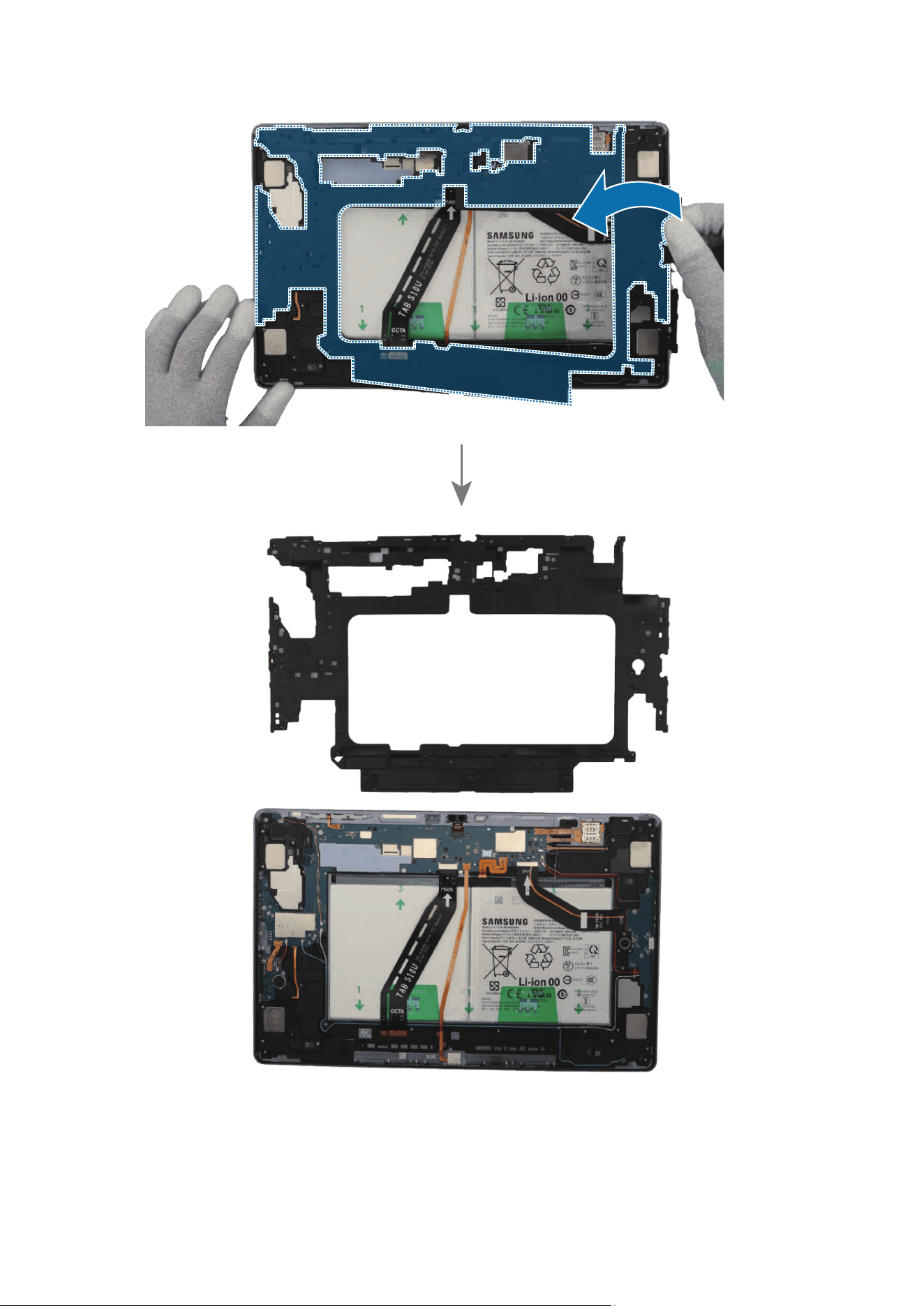
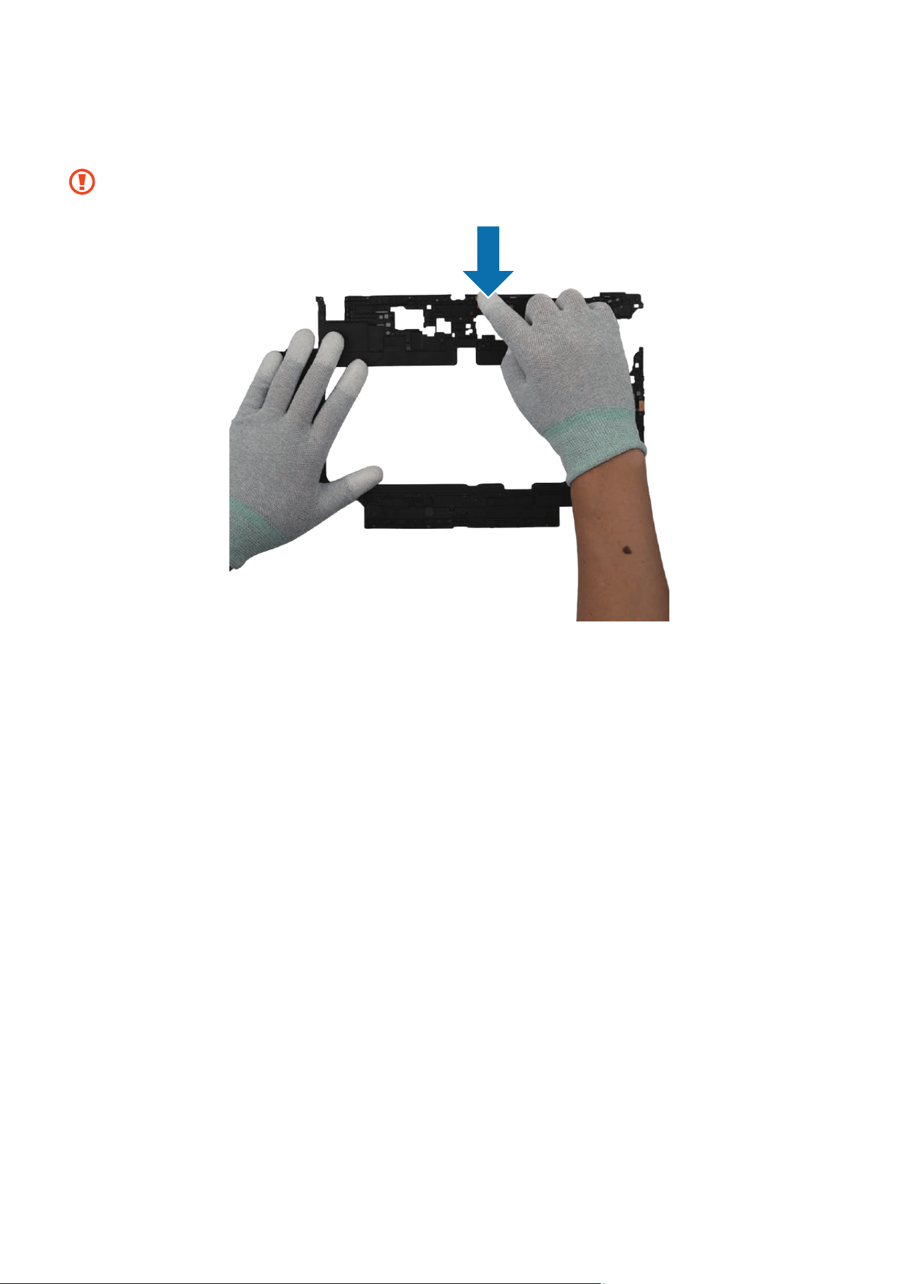
2 Using your fingers, remove the bracket from the back cover module.
Be careful not to damage the cables and near components.
Disassembly and Assembly
95
Disassembly and Assembly
96
Reassembly
Leaving screws inside the device may damage internal components, such as the
battery. When assembling, be extra careful not to leave any unassembled screws
inside the device.
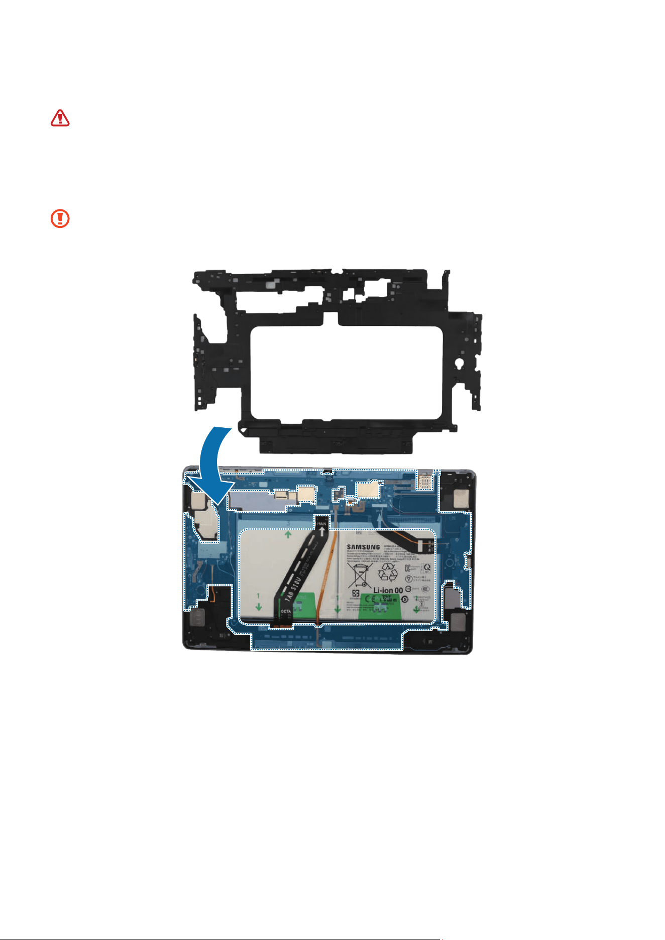
1 Using your fingers, assemble the bracket to the back cover module.
•
Be careful not to break the bracket as it is very thin.
•
Be careful not to damage the cables and near components.
Disassembly and Assembly
97
2 Check the screw 3405 (35 ea) and fasten them on the bracket using a cross-head
screwdriver.
Be careful not to damage the near components.
3 Check carefully with your fingers to see if there are any screws or other foreign
substances inside the device (battery, PBA, cable, etc.). Shake the device lightly with
the back of the device facing down to remove any remaining screws.
Reassemble the Screen to complete assembly.
Disassembly and Assembly
98
Microphone
Disassembly
•
Remove the Screen and Bracket first before you begin.
•
The microphones are already built in the bracket module. Disassemble the
microphones only if the microphones themselves require the repairs.
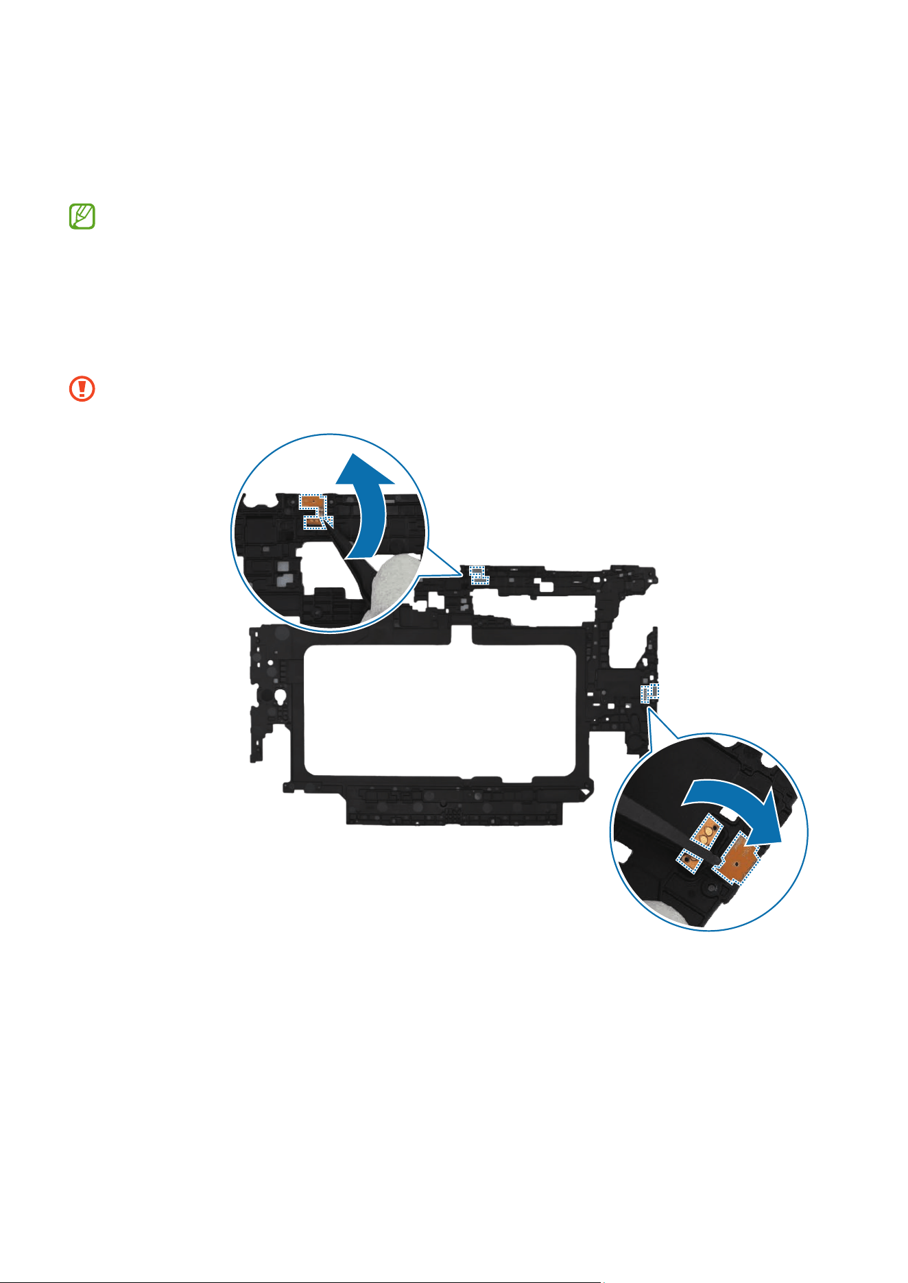
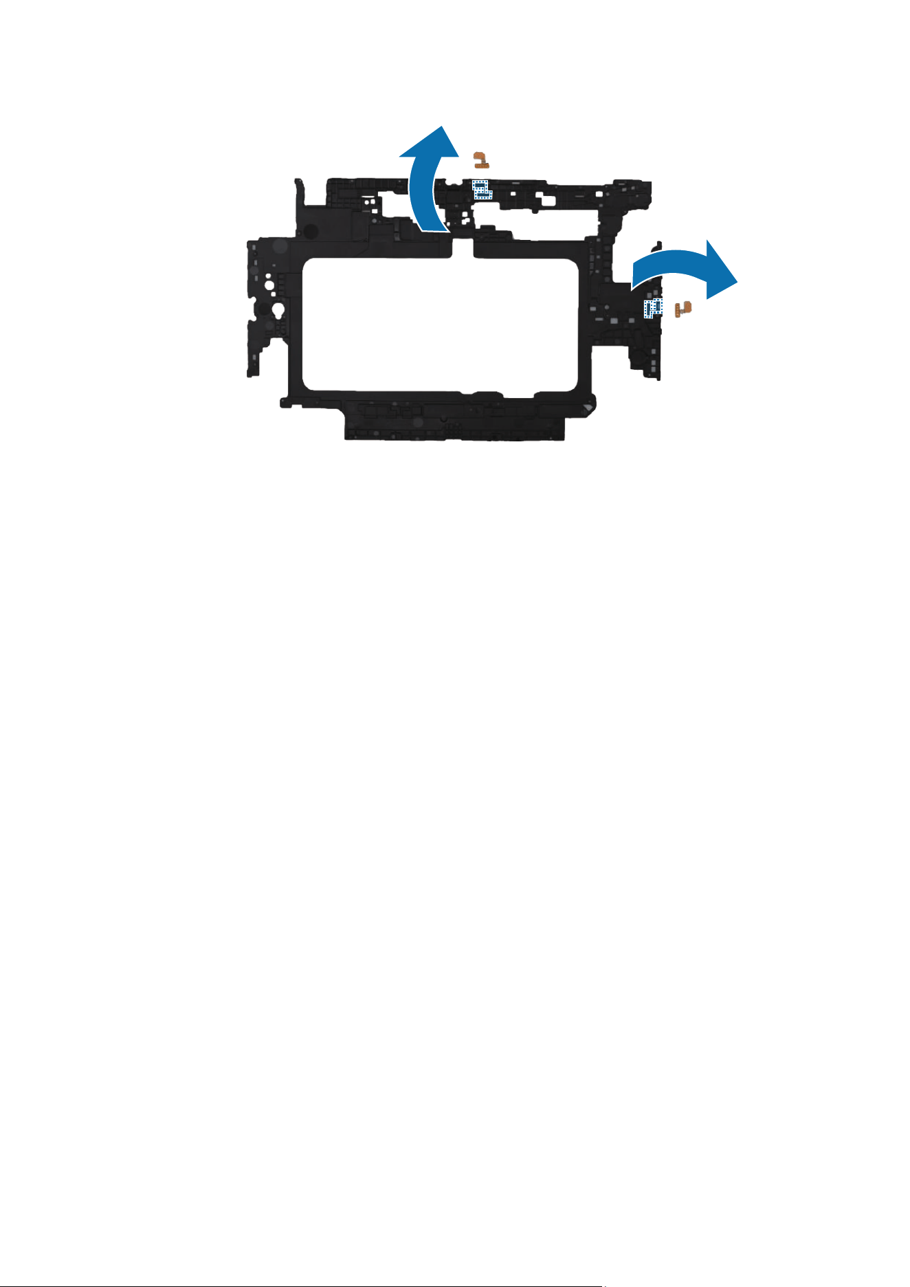
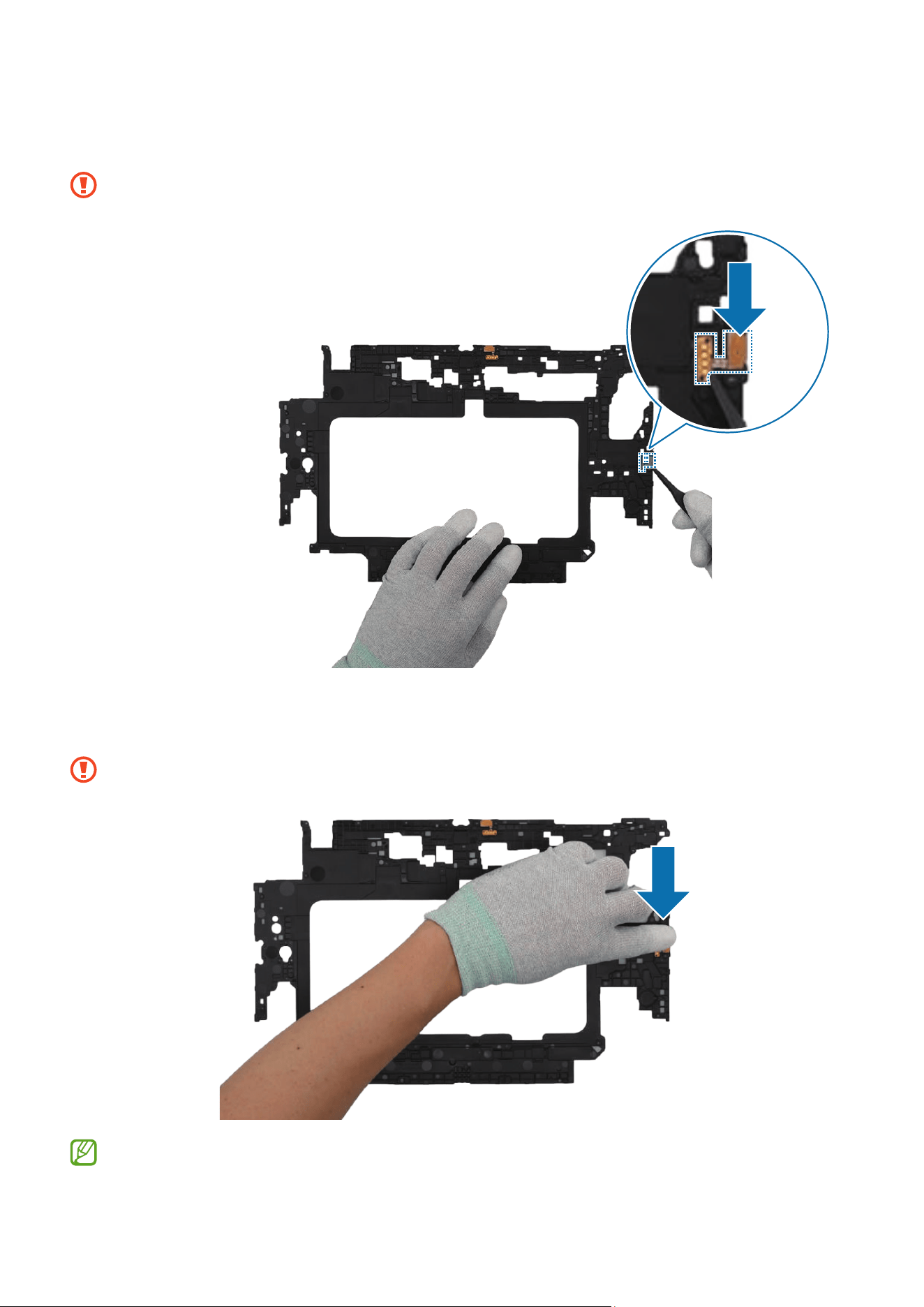
Using the tweezers, disconnect the top microphone and the side microphone from the
bracket.
Be careful not to damage the bracket.
Disassembly and Assembly
99
Disassembly and Assembly
100
Reassembly
Leaving screws inside the device may damage internal components, such as the
battery. When assembling, be extra careful not to leave any unassembled screws
inside the device.
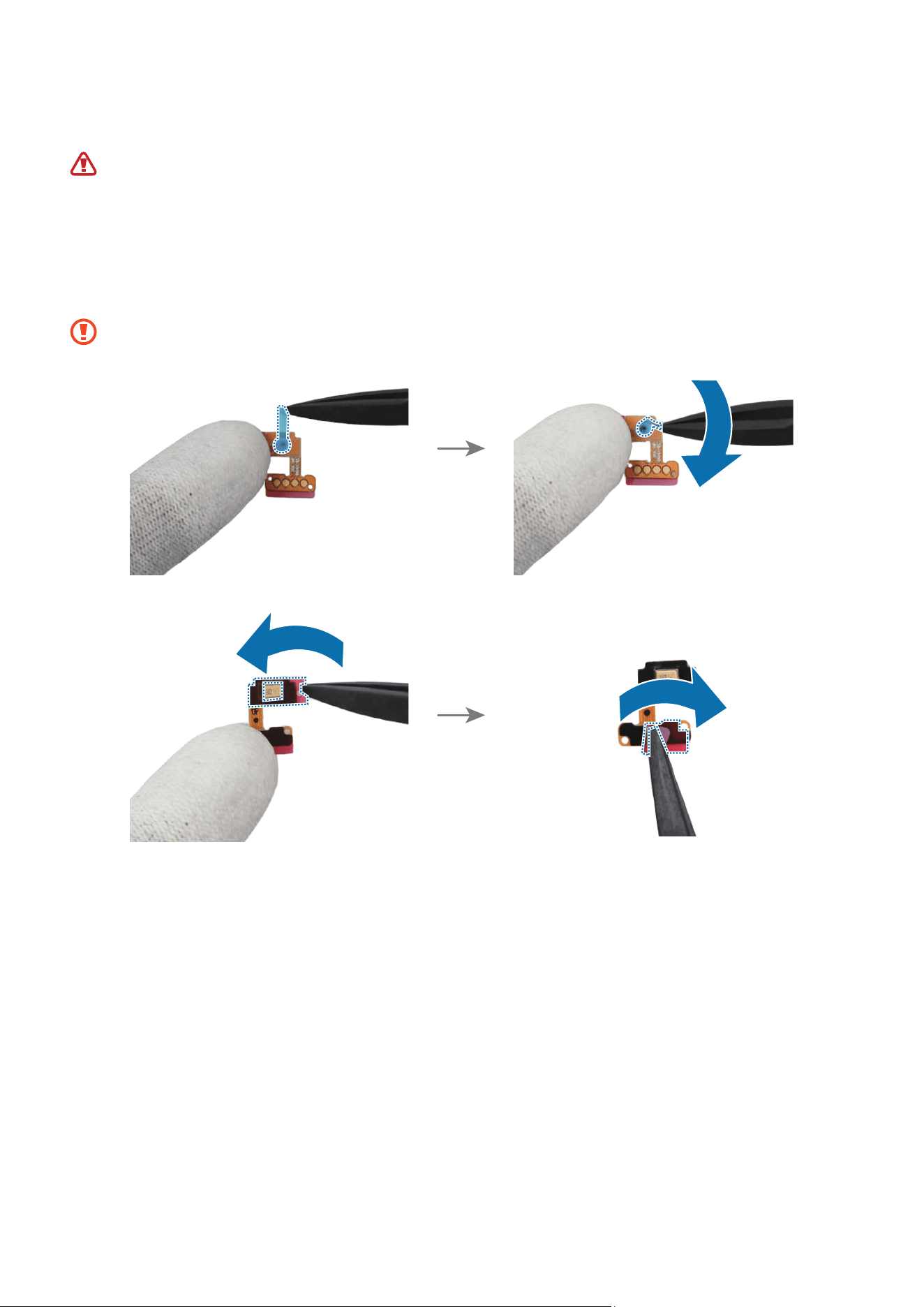
1 Using the tweezers and your fingers, remove all release films of new microphone
adhesive tapes.
Be careful not to damage the microphones.
Disassembly and Assembly
101
2 Using the tweezers, align the top microphone with the position of the microphone
hole and attach it accurately.
Be careful not to damage the microphone and bracket.
Disassembly and Assembly
102
3 Press the top microphone with your fingers softly so that the microphone can be
completely attached.
Be careful not to damage the microphone and bracket.
Disassembly and Assembly
103
4 Using the tweezers, align the side microphone with the position of the microphone
hole and attach it accurately.
Be careful not to damage the microphone and bracket.
5 Press the side microphone with your fingers softly so that the microphone can be
completely attached.
Be careful not to damage the microphone and bracket.
Reassemble the Bracket and Screen to complete assembly.

Disassembly and Assembly
104
Charging Port
Disassembly
Remove the Screen and Bracket first before you begin.
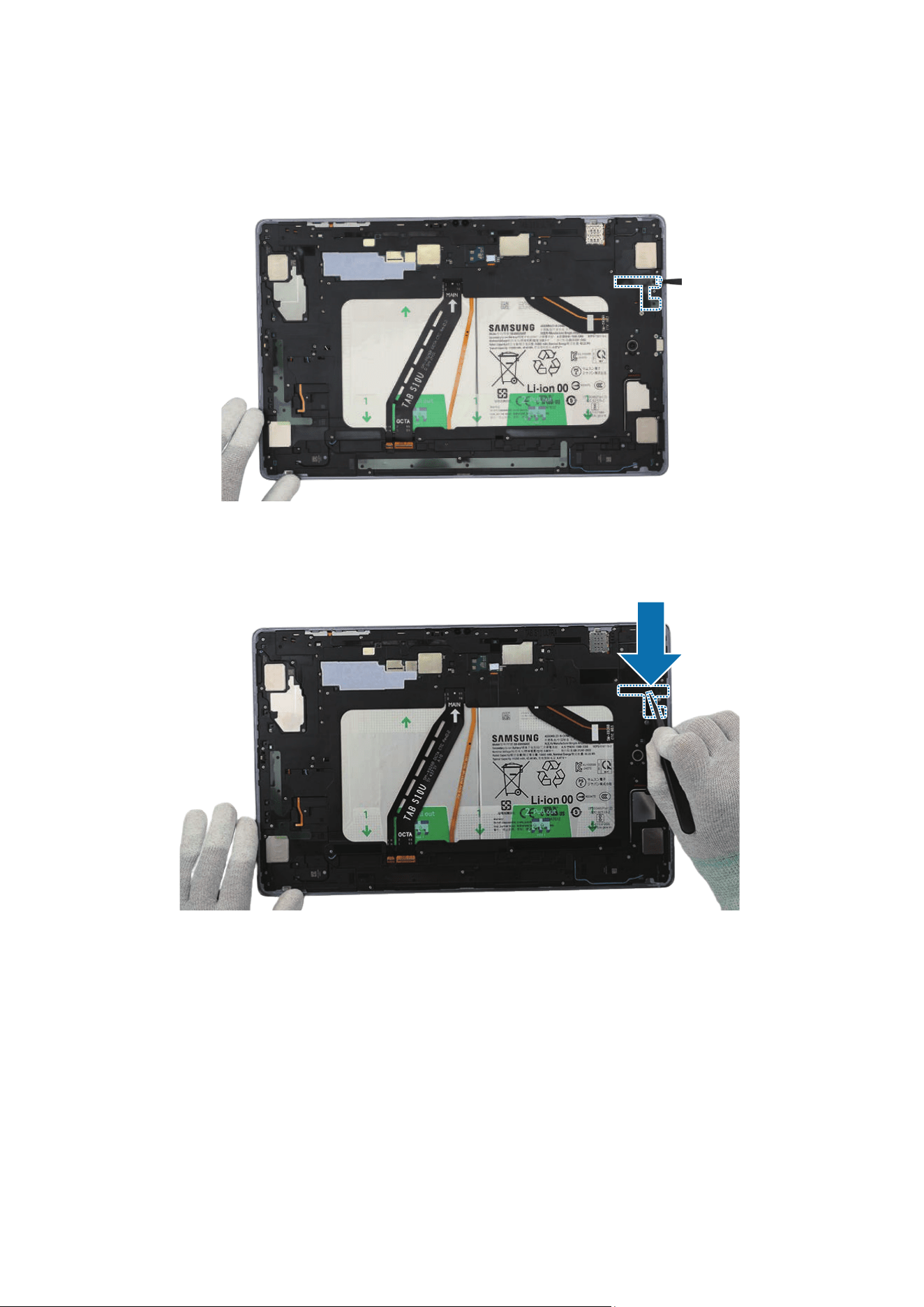
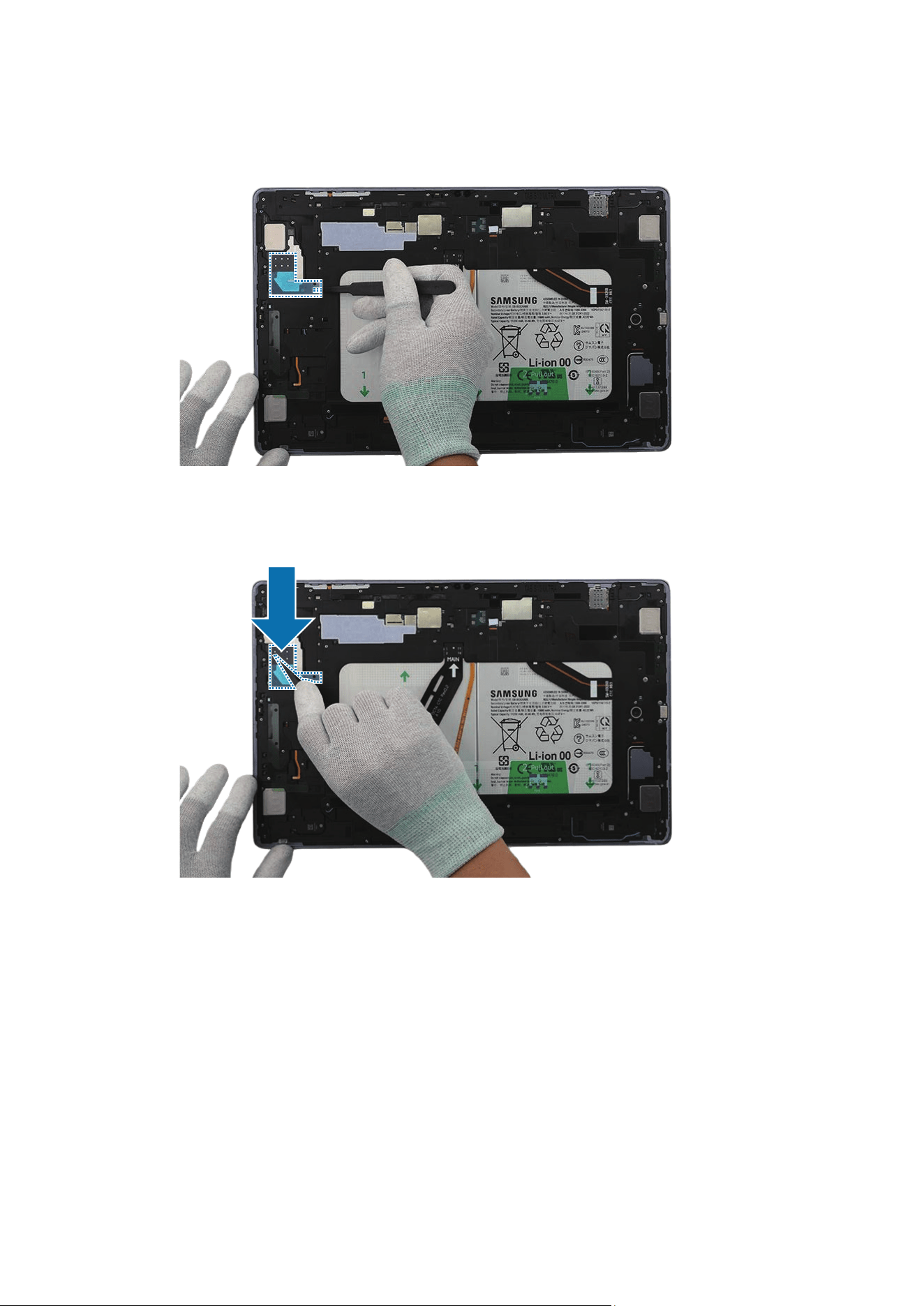
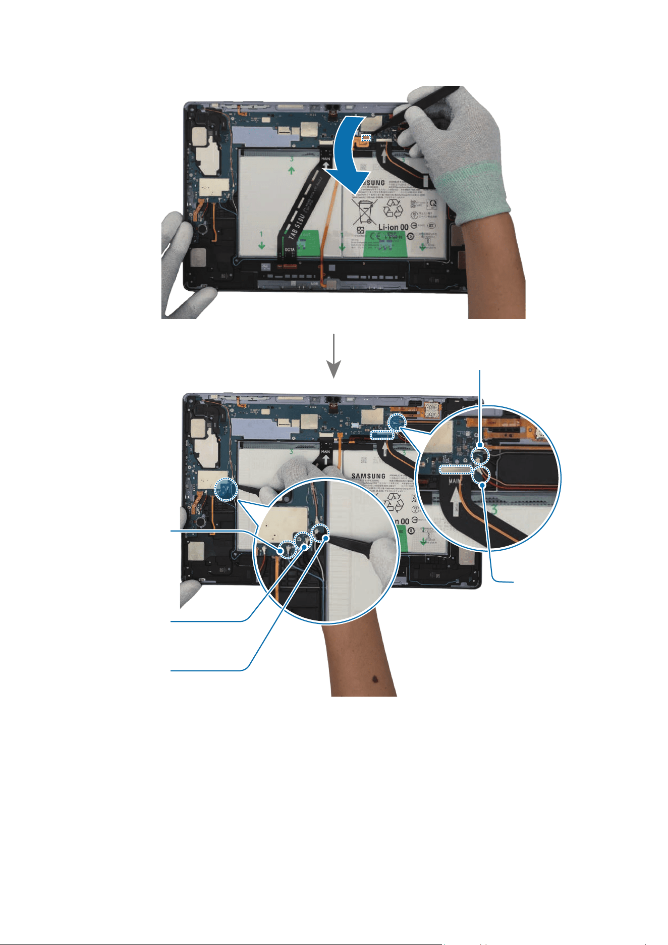
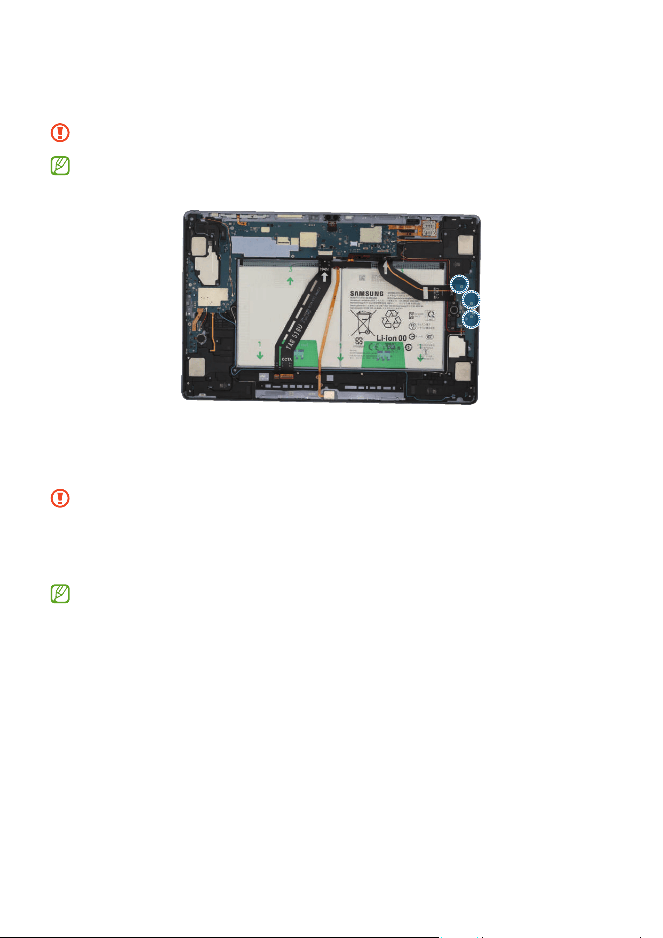
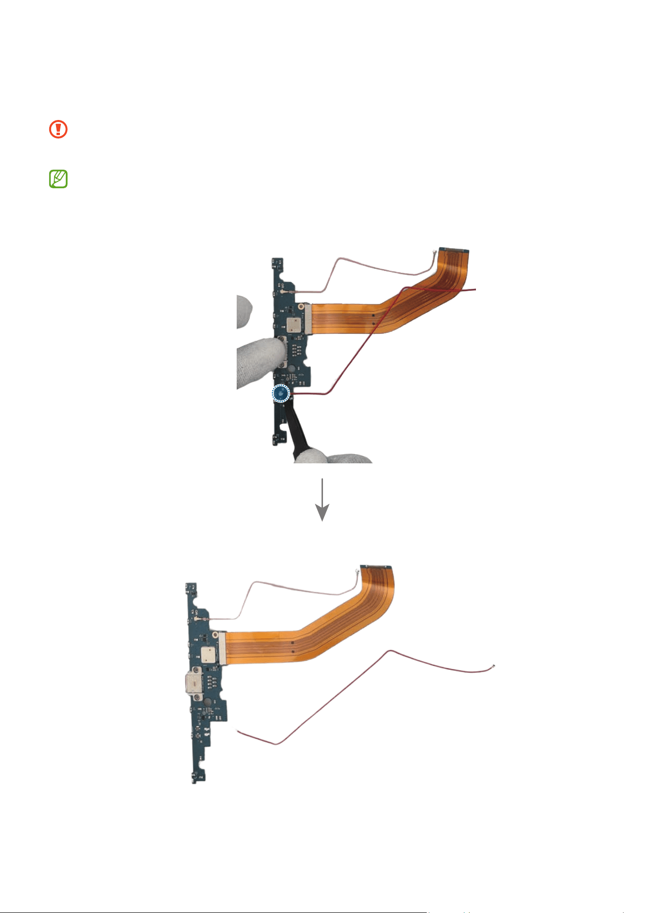
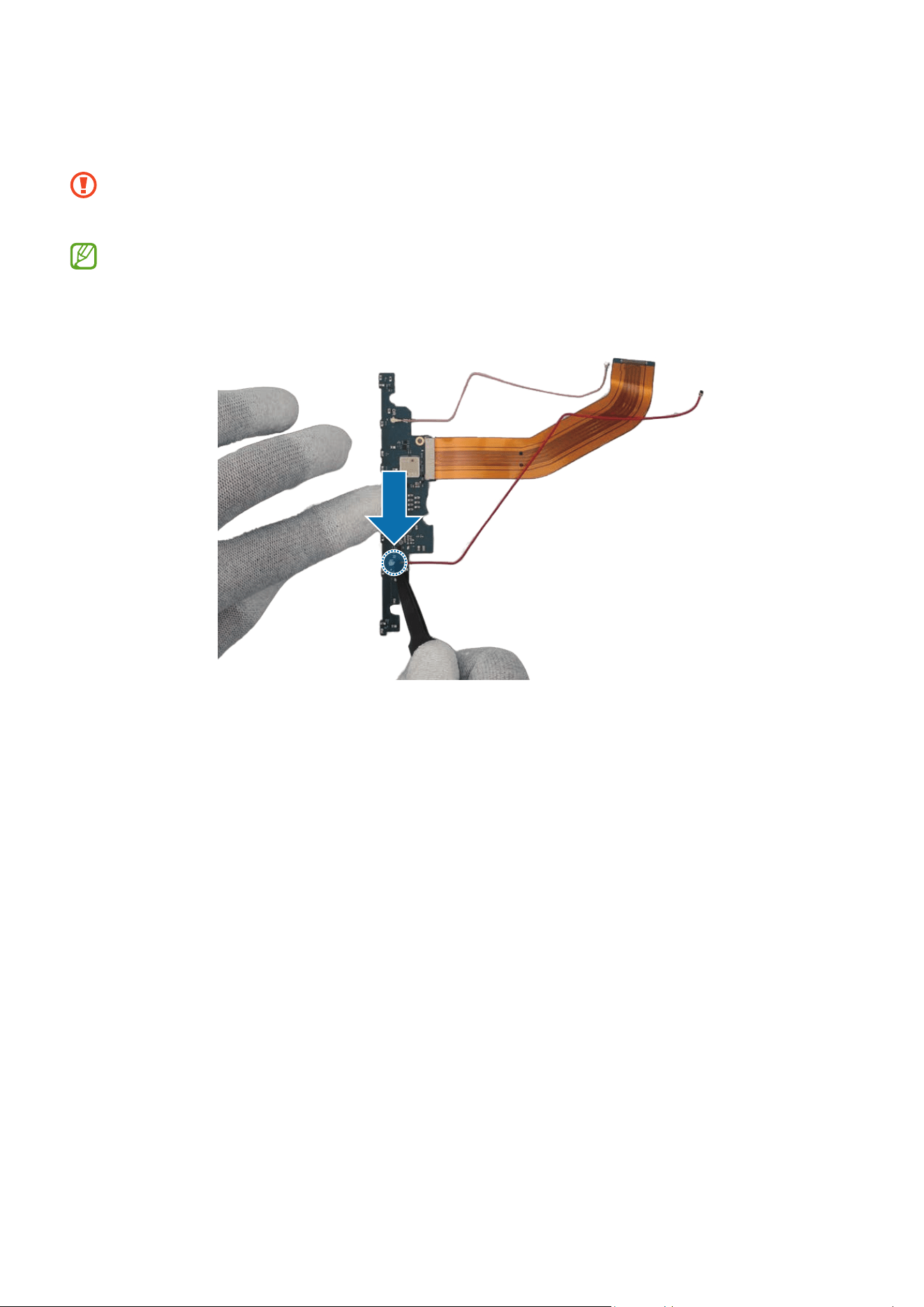
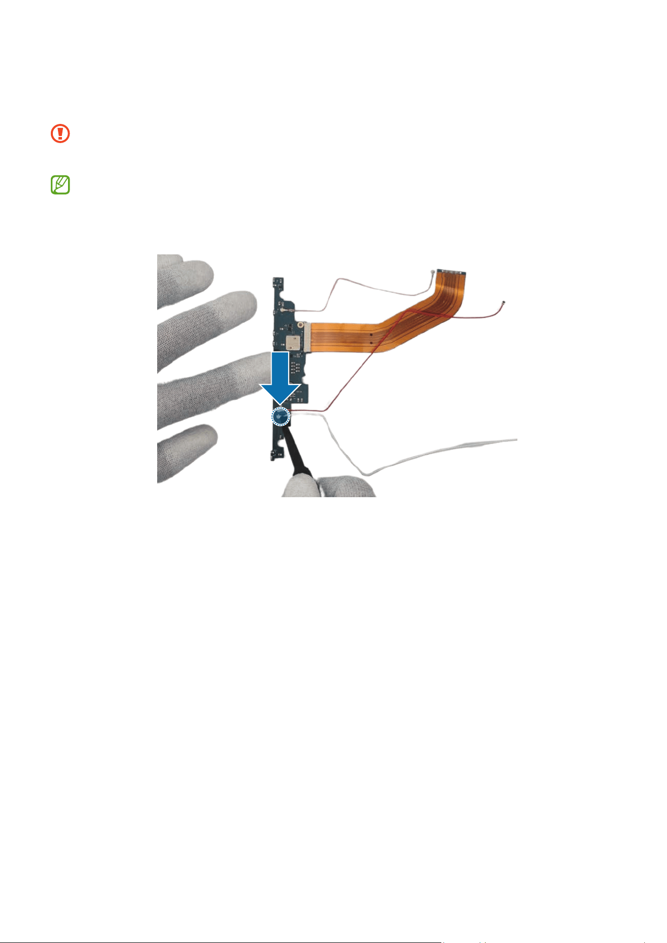
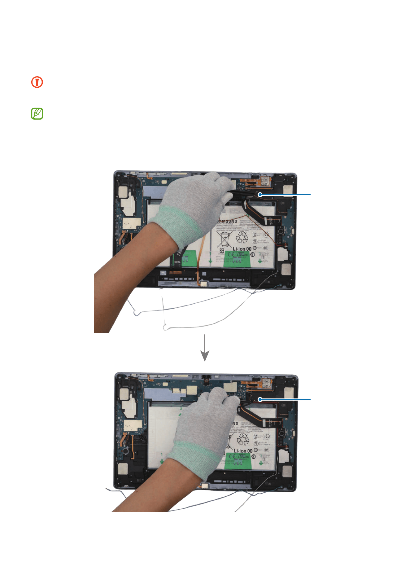
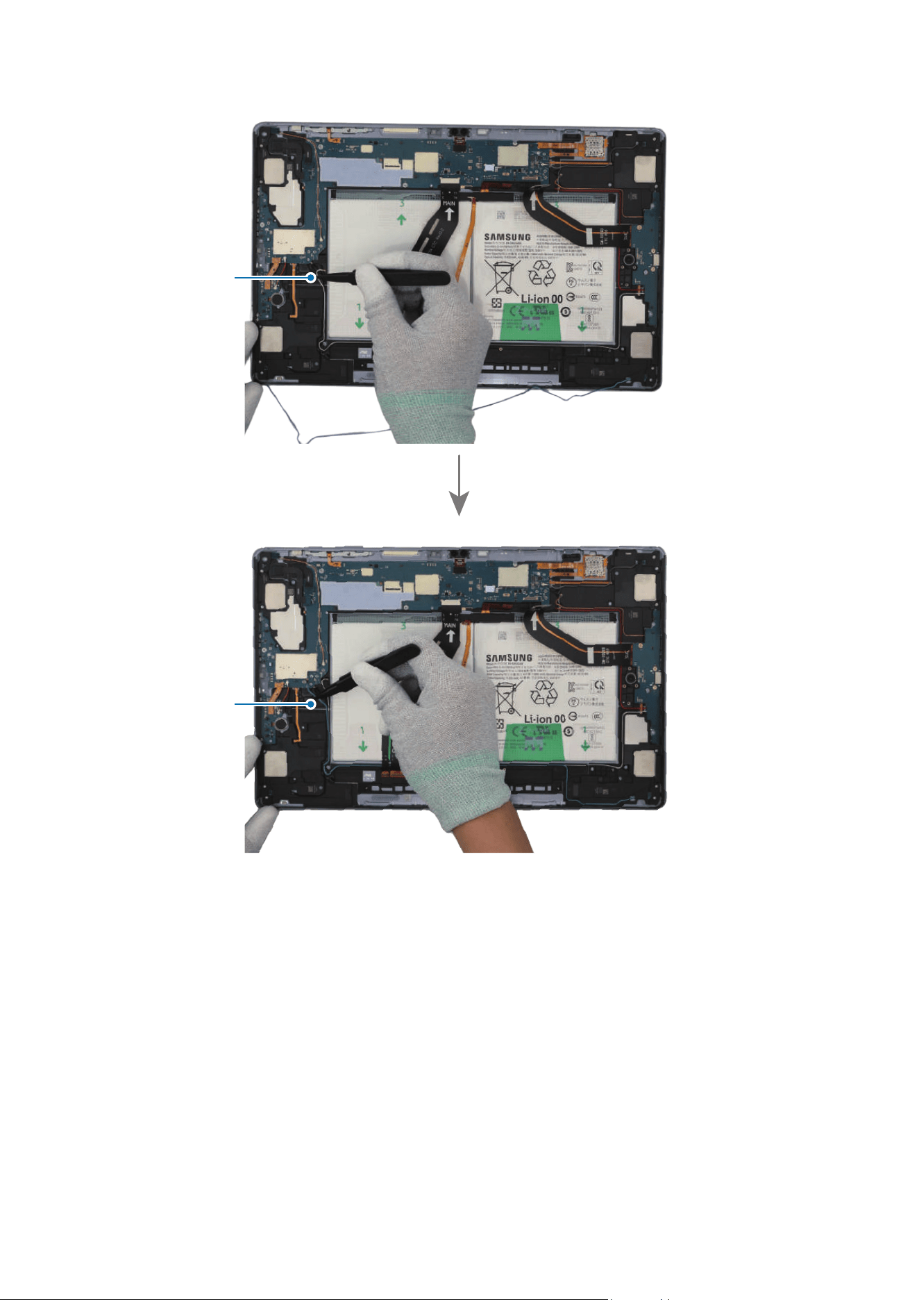
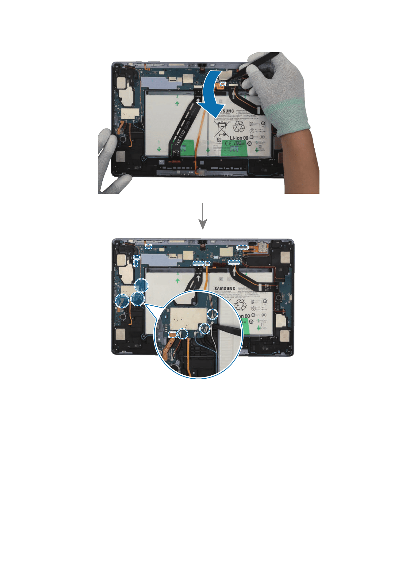
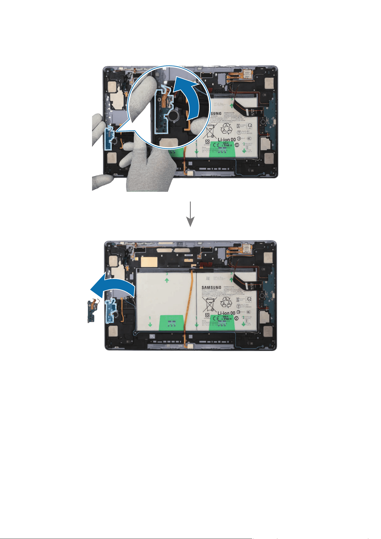
1 Using the tweezers, disconnect the battery connector from the main board first.
Separate the 2 connectors and the coaxial cable connector (Black) from the main
board. For the 5G or LTE devices, separate the additional 4 coaxial cable connectors
(Blue/White/Orange/Red).
•
Make sure to first disconnect the battery connector for your own safety.
•
Be careful not to damage the battery.
•
Be careful not to damage the cable while removing the connector.
•
Be careful not to damage the near components.
•
The 4 coaxial cables (Blue/White/Orange/Red) are only available for the 5G or
LTE devices.
•
The cables and connectors may vary depending on the country, region, or
specifications.
Disassembly and Assembly
105
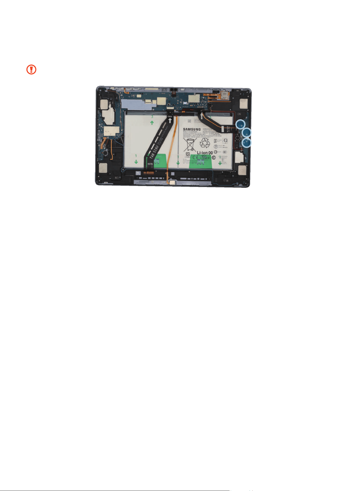
Coaxial cable (Orange)
Coaxial cable
(Red)
Coaxial cable
(Black)
Coaxial cable
(White)
Coaxial cable
(Blue)
Disassembly and Assembly
106
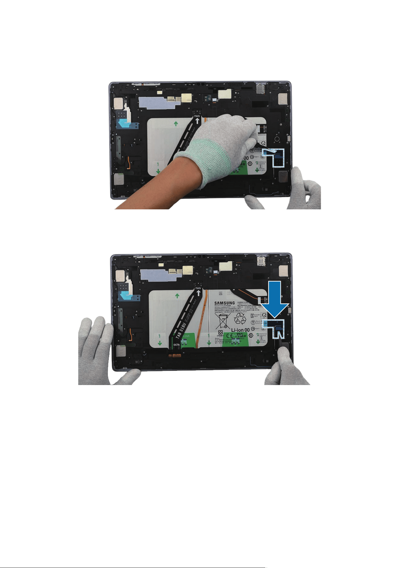
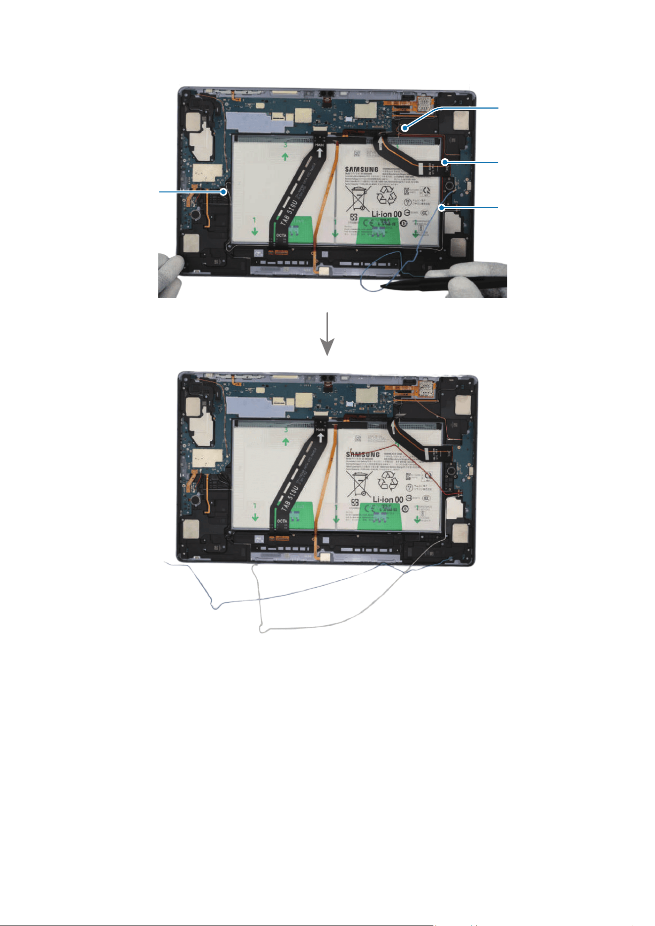
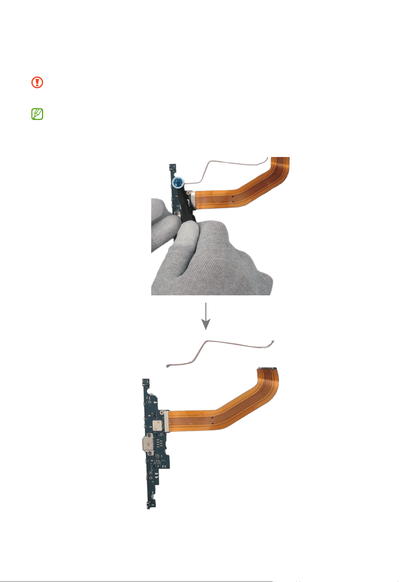
2 Check and remove the screws at the 3 different points on the charging port using a
cross-head screwdriver.
Be careful not to damage the near components.
Check the number of screws that have been removed, and store them carefully to
make sure that no unassembled screws are left inside the device during assembly.
3 For the 5G or LTE devices, disconnect the 4 coaxial cables (Blue/White/Orange/
Red) in the speaker modules with the tweezers. Using the tweezers, lift up on the
separator groove of the charging port module and remove it carefully.
•
Check the position of the overlapping cables and disconnect them in order from
the top.
•
Be careful not to damage the cable while removing the connector.
•
Be careful not to damage the near components.
•
The 4 coaxial cables (Blue/White/Orange/Red) are only available for the 5G or
LTE devices.
•
The cables and connectors may vary depending on the country, region, or
specifications.
Disassembly and Assembly
107
Coaxial cable
(Blue)
Coaxial cable
(Red)
Coaxial cable
(Orange)
Coaxial cable
(White)
Disassembly and Assembly
108
Disassembly and Assembly
109
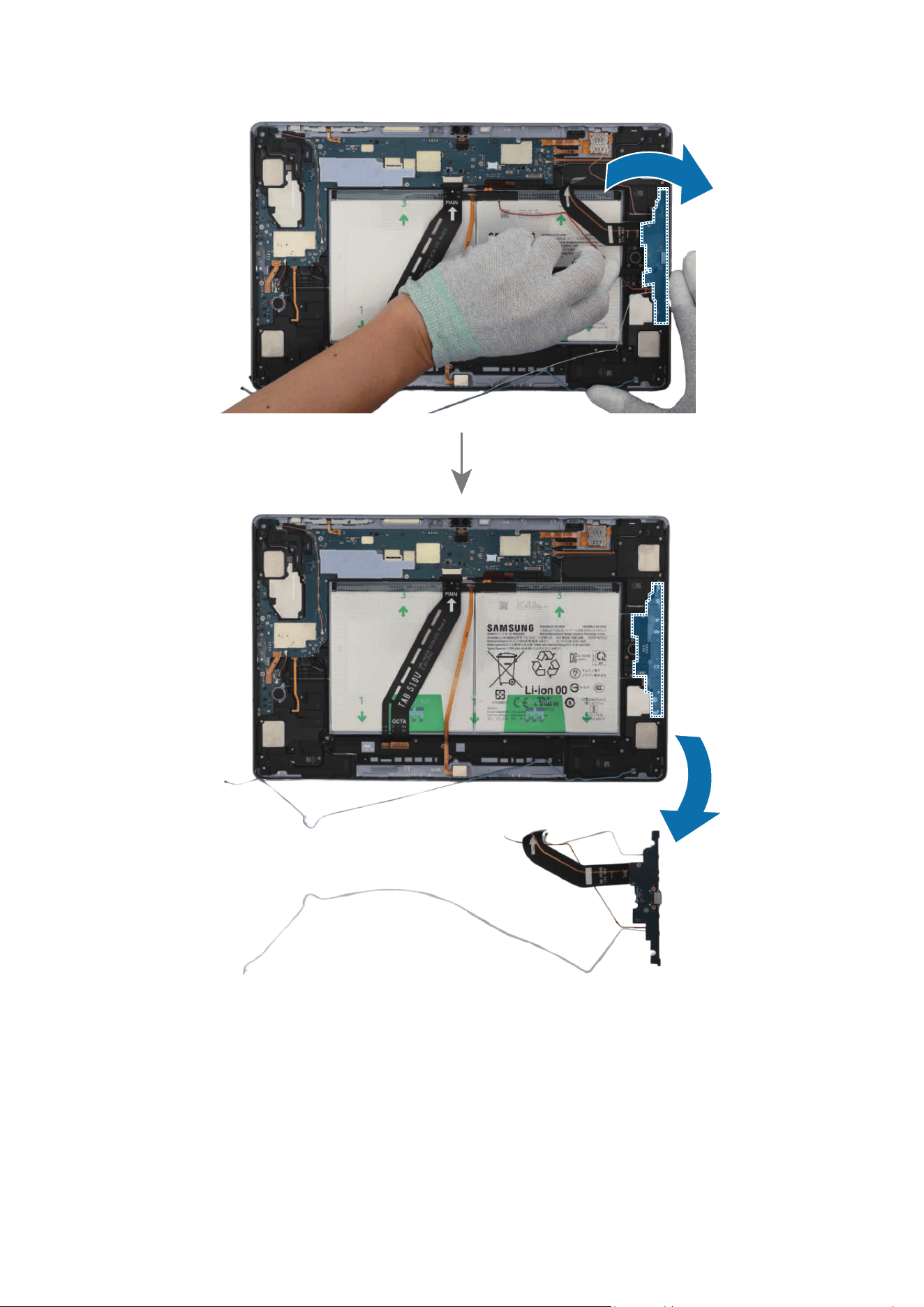
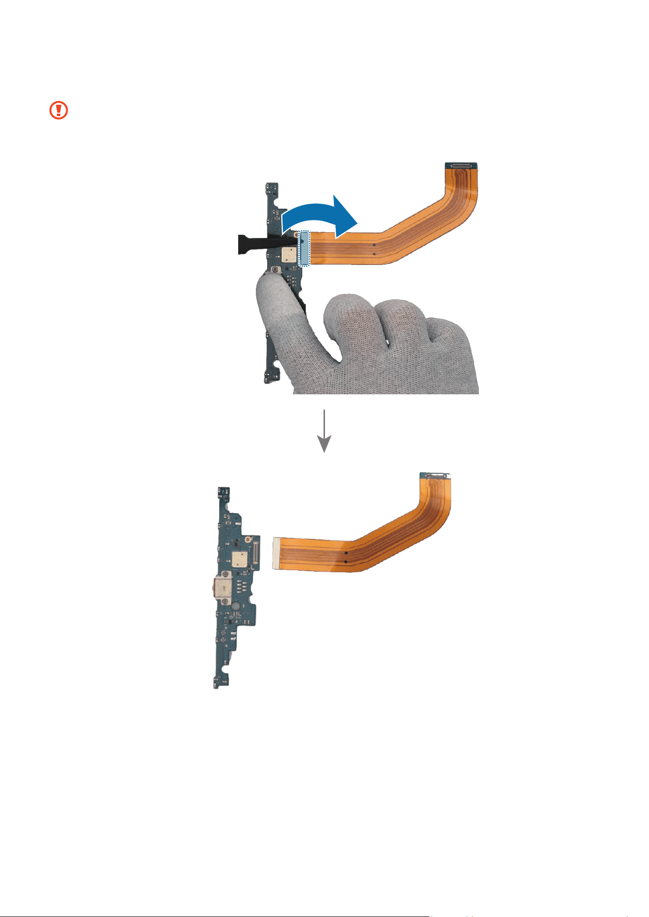
4 For the 5G or LTE devices, disconnect the coaxial cable connector (White) on the back
of the charging port with the tweezers.
•
Be careful not to damage the near components.
•
Be careful not to damage the cable while removing the connector.
•
The coaxial cable (White) is only available for the 5G or LTE devices.
•
The cables and connectors may vary depending on the country, region, or
specifications.
Disassembly and Assembly
110
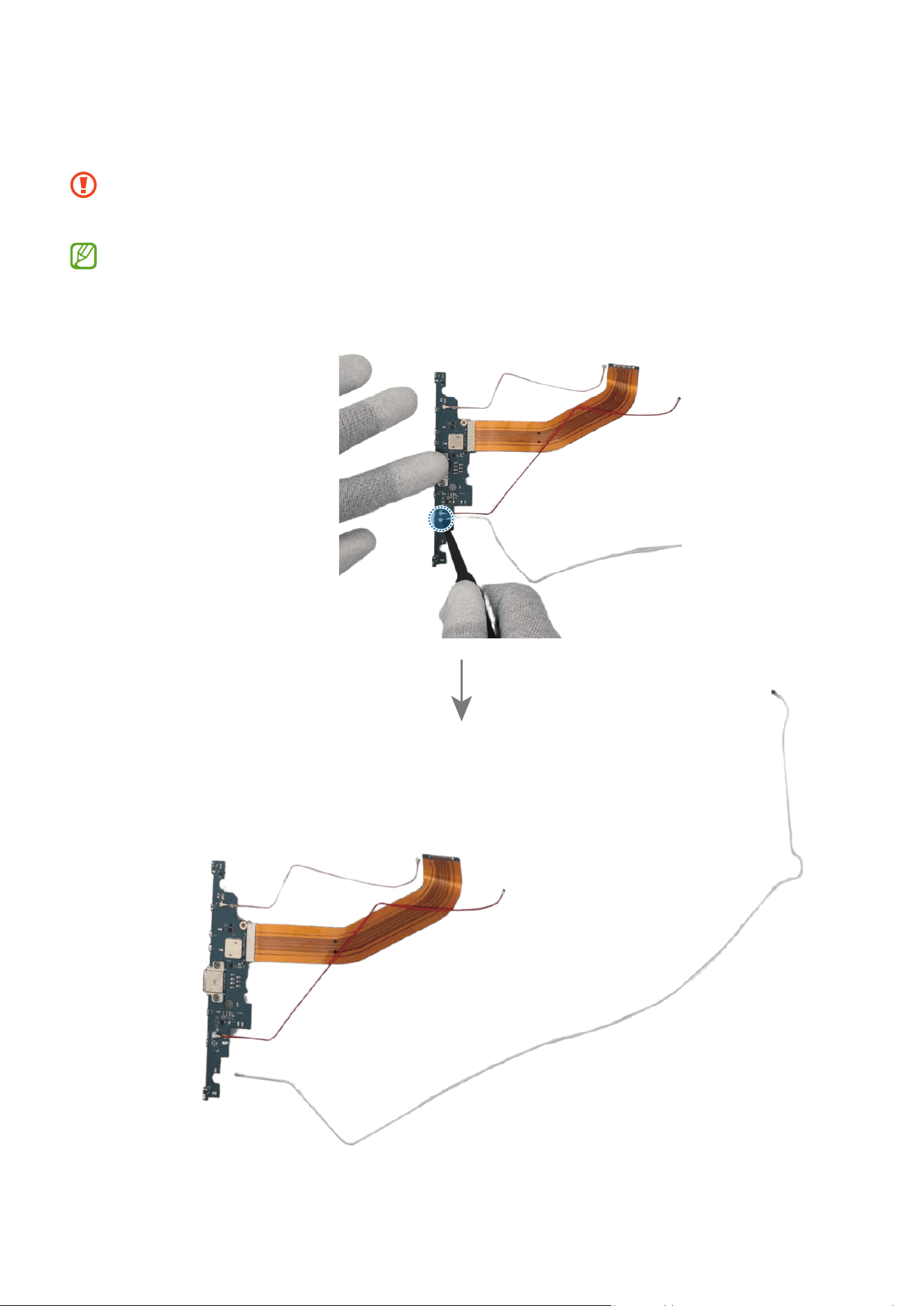
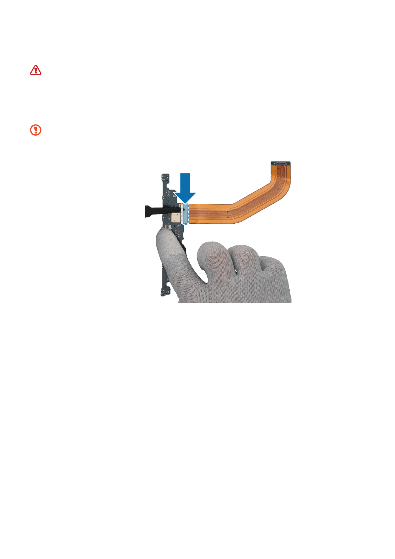
5 For the 5G or LTE devices, disconnect the coaxial cable connector (Red) on the back of
the charging port with the tweezers.
•
Be careful not to damage the near components.
•
Be careful not to damage the cable while removing the connector.
•
The coaxial cable (Red) is only available for the 5G or LTE devices.
•
The cables and connectors may vary depending on the country, region, or
specifications.
Disassembly and Assembly
111
6 For the 5G or LTE devices, disconnect the coaxial cable connector (Orange) on the
back of the charging port with the tweezers.
•
Be careful not to damage the near components.
•
Be careful not to damage the cable while removing the connector.
•
The coaxial cable (Orange) is only available for the 5G or LTE devices.
•
The cables and connectors may vary depending on the country, region, or
specifications.
Disassembly and Assembly
112
7 Using the tweezers, disconnect the connector on the back of the charging port.
•
Be careful not to damage the near components.
•
Be careful not to damage the cable while removing the connector.
Disassembly and Assembly
113
Reassembly
Leaving screws inside the device may damage internal components, such as the
battery. When assembling, be extra careful not to leave any unassembled screws
inside the device.
1 Using the tweezers, connect the connector on the back of the charging port.
•
Be careful not to damage the charging port and near components.
•
Be careful not to damage the cable while connecting the connector.
Disassembly and Assembly
114
2 For the 5G or LTE devices, connect the coaxial cable connector (Orange) on the back of
the charging port with the tweezers.
•
Be careful not to damage the charging port and near components.
•
Be careful not to damage the cable while connecting the connector.
•
The coaxial cable (Orange) is only available for the 5G or LTE devices.
•
The cables and connectors may vary depending on the country, region, or
specifications.
Disassembly and Assembly
115
3 For the 5G or LTE devices, connect the coaxial cable connector (Red) on the back of
the charging port with the tweezers.
•
Be careful not to damage the charging port and near components.
•
Be careful not to damage the cable while connecting the connector.
•
The coaxial cable (Red) is only available for the 5G or LTE devices.
•
The cables and connectors may vary depending on the country, region, or
specifications.
Disassembly and Assembly
116
4 For the 5G or LTE devices, connect the coaxial cable connector (White) on the back of
the charging port with the tweezers.
•
Be careful not to damage the charging port and near components.
•
Be careful not to damage the cable while connecting the connector.
•
The coaxial cable (White) is only available for the 5G or LTE devices.
•
The cables and connectors may vary depending on the country, region, or
specifications.
Disassembly and Assembly
117
5 Using the tweezers or your fingers, assemble the charging port to the back cover
module and press down softly and evenly on it so that the charging port can be
completely attached.
•
Be careful not to damage the charging port module side contact.
•
Be careful not to damage the near components.
Disassembly and Assembly
118
6 For the 5G or LTE devices, carefully connect the cables (Orange/Red/White/Blue) to
the speaker modules.
•
Be careful not to damage the charging port and near components.
•
Be careful not to damage the cables.
•
The 4 coaxial cables (Orange/Red/White/Blue) are only available for the 5G or
LTE devices.
•
The cables and connectors may vary depending on the country, region, or
specifications.
Coaxial cable
(Orange)
Coaxial cable
(Red)
Disassembly and Assembly
119
Coaxial cable
(White)
Coaxial cable
(Blue)
Disassembly and Assembly
120
7 Check the screw 3443 (3 ea) and fasten them on the charging port using a cross-head
screwdriver.
Be careful not to damage the charging port and near components.
Disassembly and Assembly
121
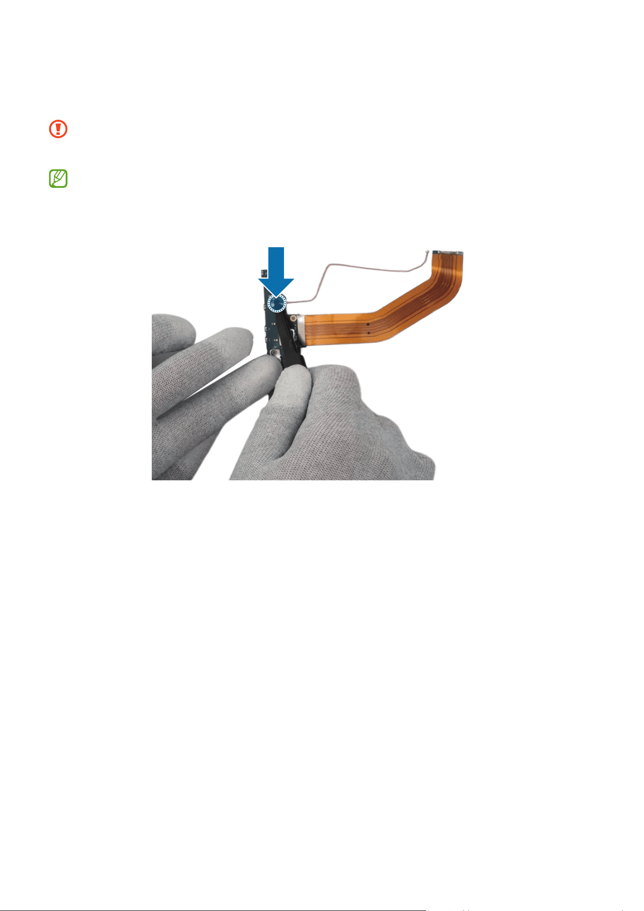
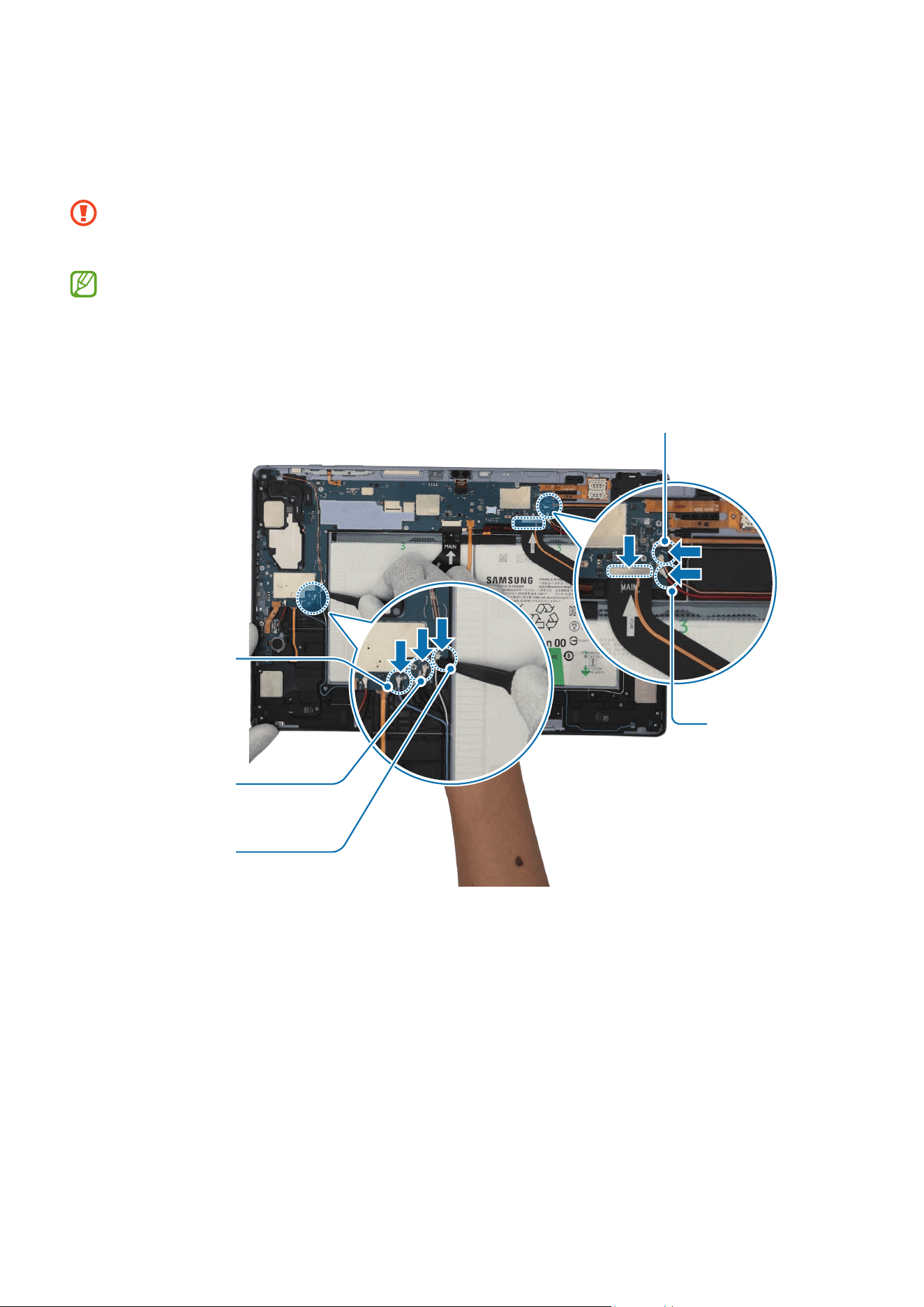
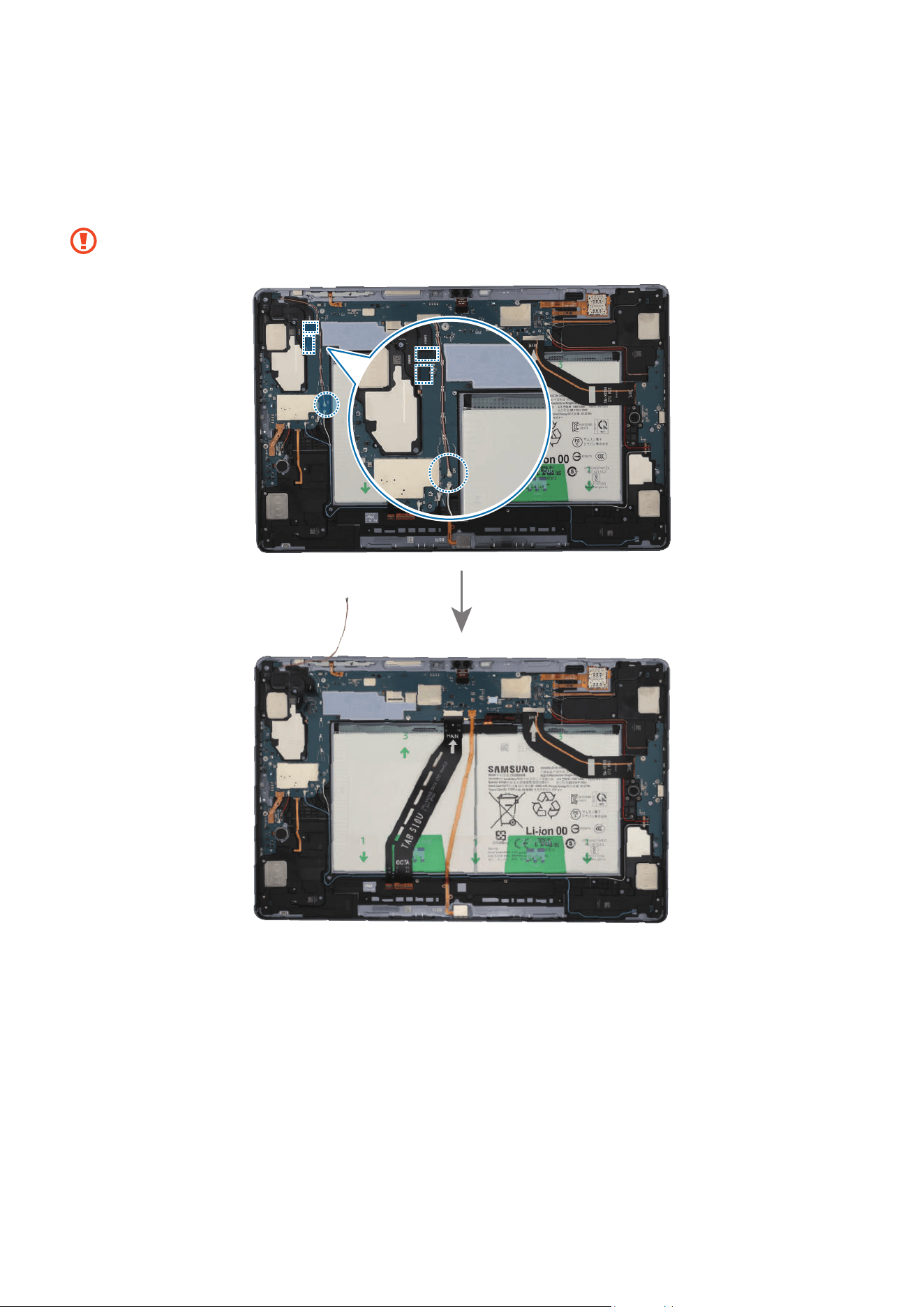
8 Using the tweezers, connect the 2 connectors and the coaxial cable connector (Black)
to the main board. For the 5G or LTE devices, connect the 4 coaxial cable connectors
(Blue/White/Orange/Red).
•
Be careful not to damage the charging port and near components.
•
Be careful not to damage the cable while connecting the connector.
•
The 4 coaxial cables (Blue/White/Orange/Red) are only available for the 5G or
LTE devices.
•
The cables and connectors may vary depending on the country, region, or
specifications.
Coaxial cable
(Red)
Coaxial cable
(Black)
Coaxial cable
(White)
Coaxial cable
(Blue)
Coaxial cable (Orange)


Disassembly and Assembly
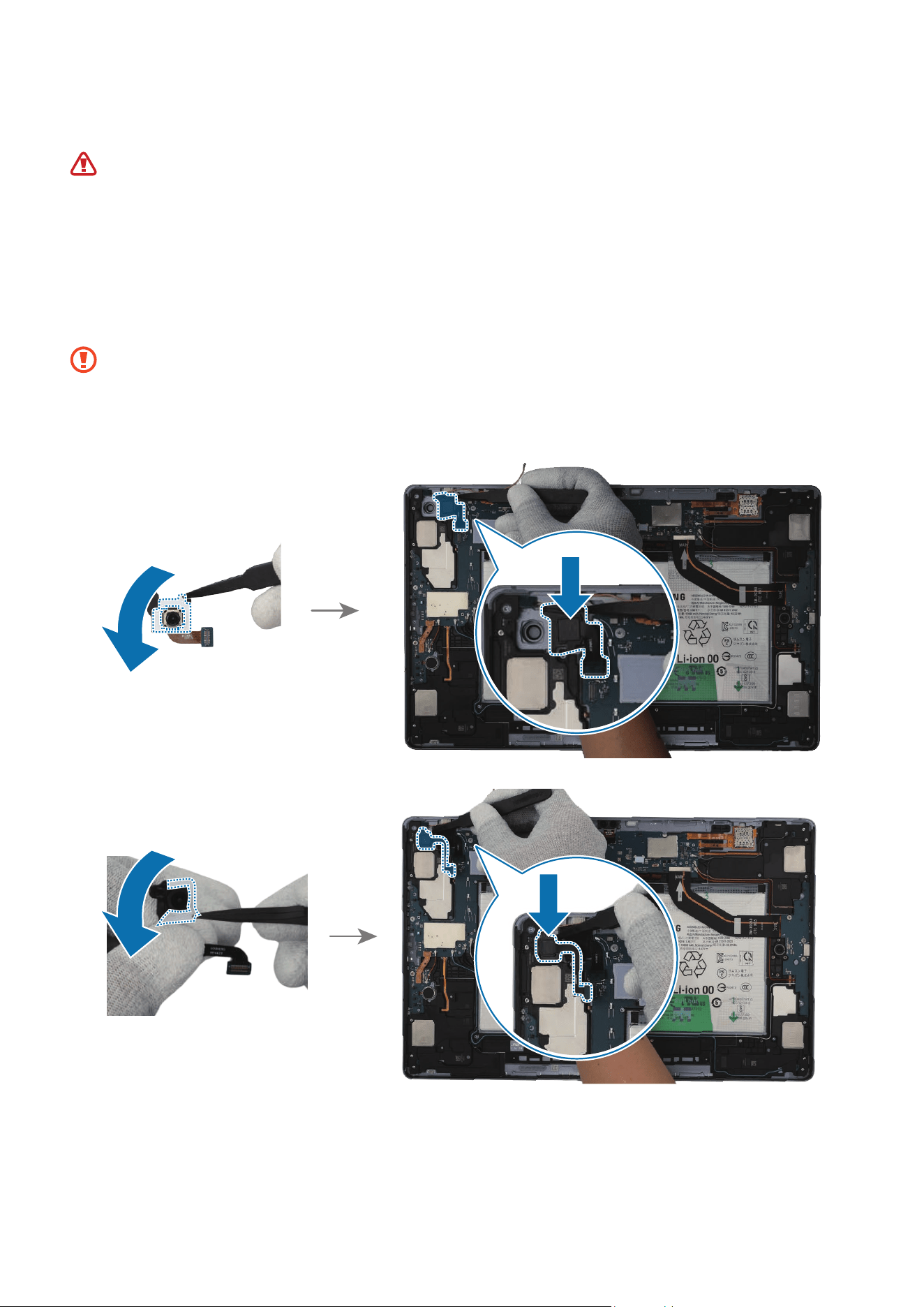
124
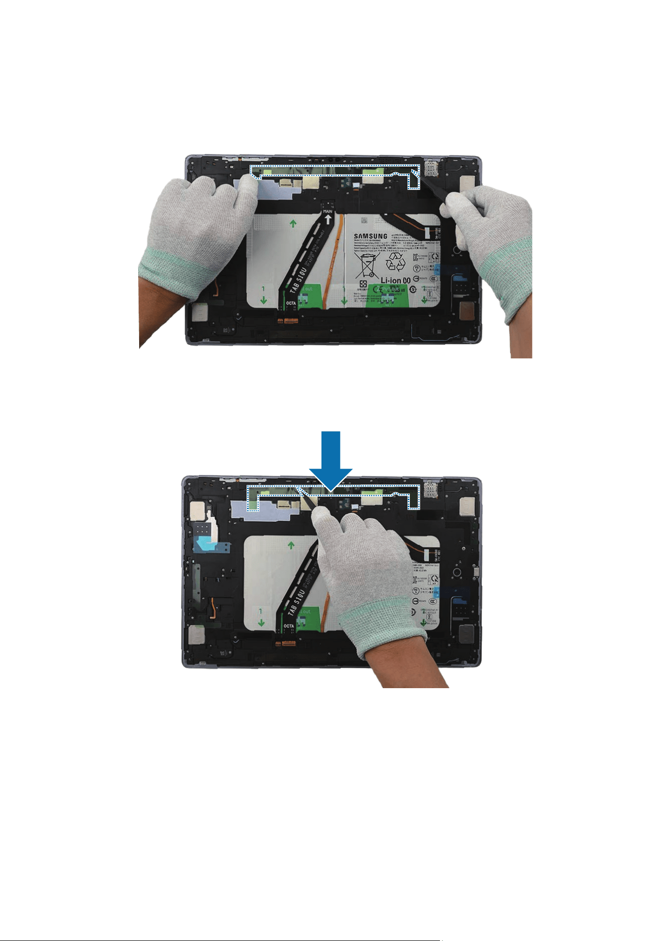
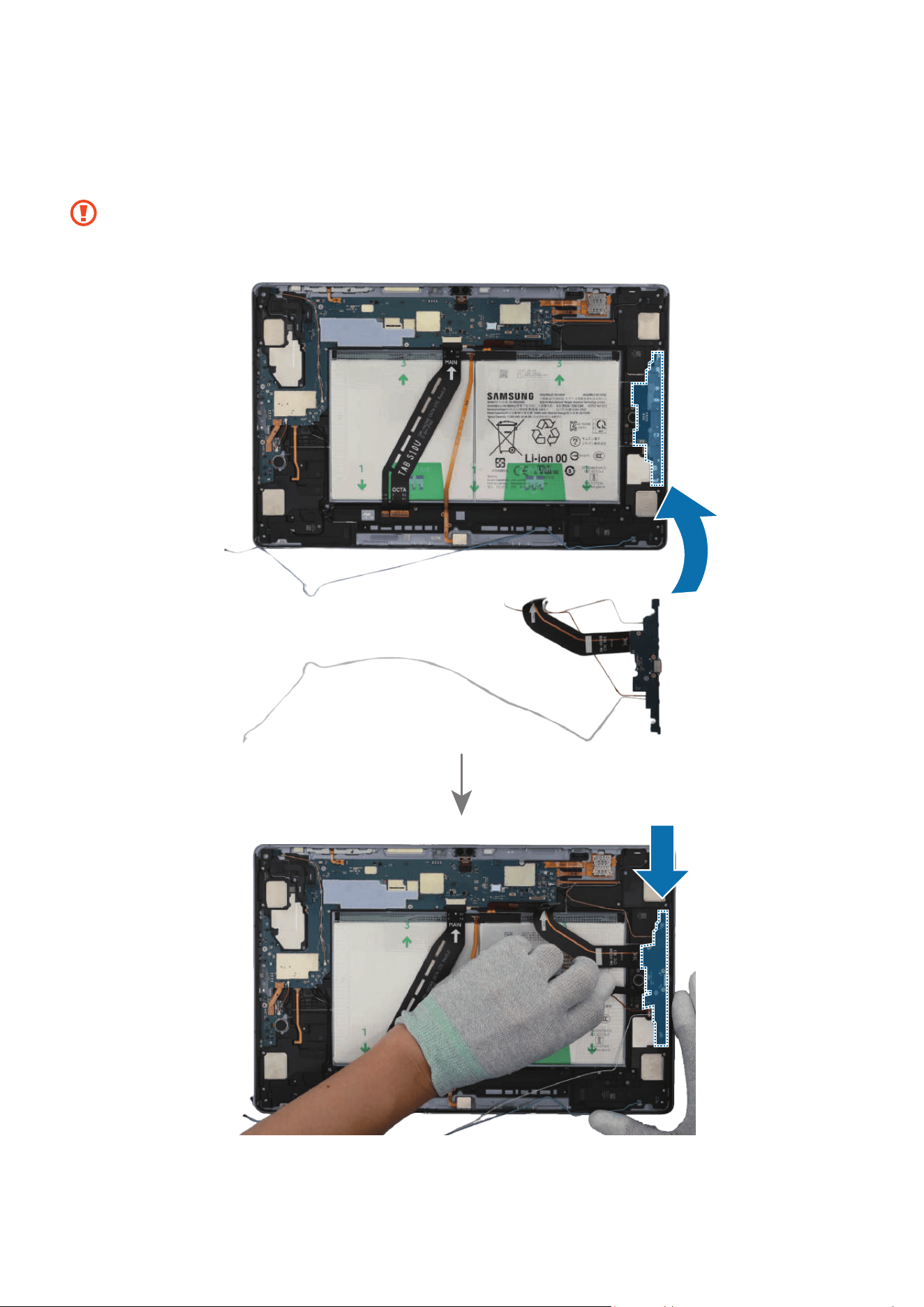
2 Using the tweezers, disconnect the coaxial cable connector (Orange) and 2 rear
camera cable connectors from the main board. Using the tweezers, lift the separator
groove up to the top of the rear camera module and remove the 2 rear cameras one
by one. Leave the camera lens facing up.
Be careful not to damage the main board and near components.
Disassembly and Assembly
125
Disassembly and Assembly
126
Reassembly
Leaving screws inside the device may damage internal components, such as the
battery. When assembling, be extra careful not to leave any unassembled screws
inside the device.
1 Using the tweezers and your fingers, remove all release films from the new rear
cameras. Using the tweezers or your fingers, gently insert the 2 rear camera modules
one by one in the camera holes so that the lens faces backward.
•
Make sure to place the camera in the correct position.
•
Be careful not to damage the camera lens and near components.
•
Be careful not to damage and scratch the camera module.
Disassembly and Assembly
127
2 Press down softly and evenly on the camera modules so that the rear cameras can be
fully inserted.
3 Using the tweezers, connect the coaxial cable connector (Orange) and 2 rear camera
cable connectors to the main board.
•
Be careful not to damage the cable while connecting the connector.
•
Be careful not to damage the near components.

Disassembly and Assembly
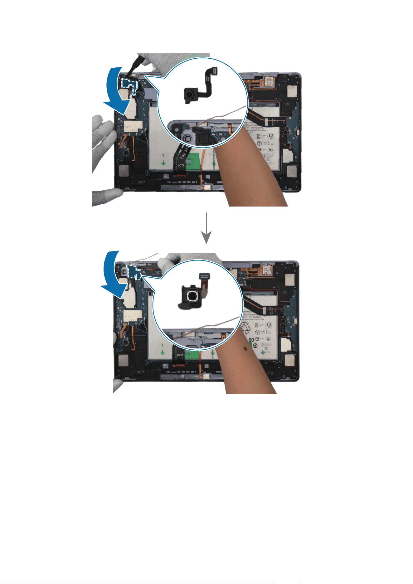
130
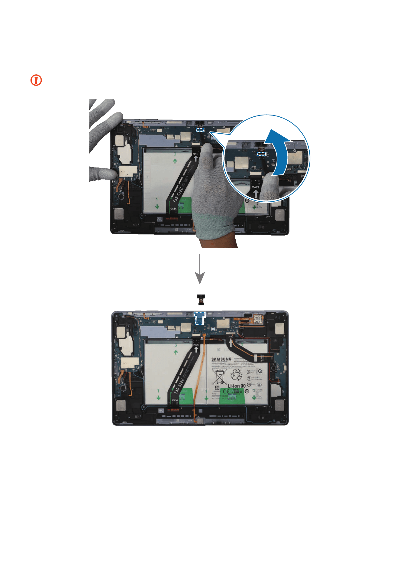
2 Using the tweezers, separate the front camera connector from the main board and
remove the front camera carefully from the device. Leave the camera lens facing up.
Be careful not to damage the main board and near components.
Disassembly and Assembly
131
Reassembly
Leaving screws inside the device may damage internal components, such as the
battery. When assembling, be extra careful not to leave any unassembled screws
inside the device.
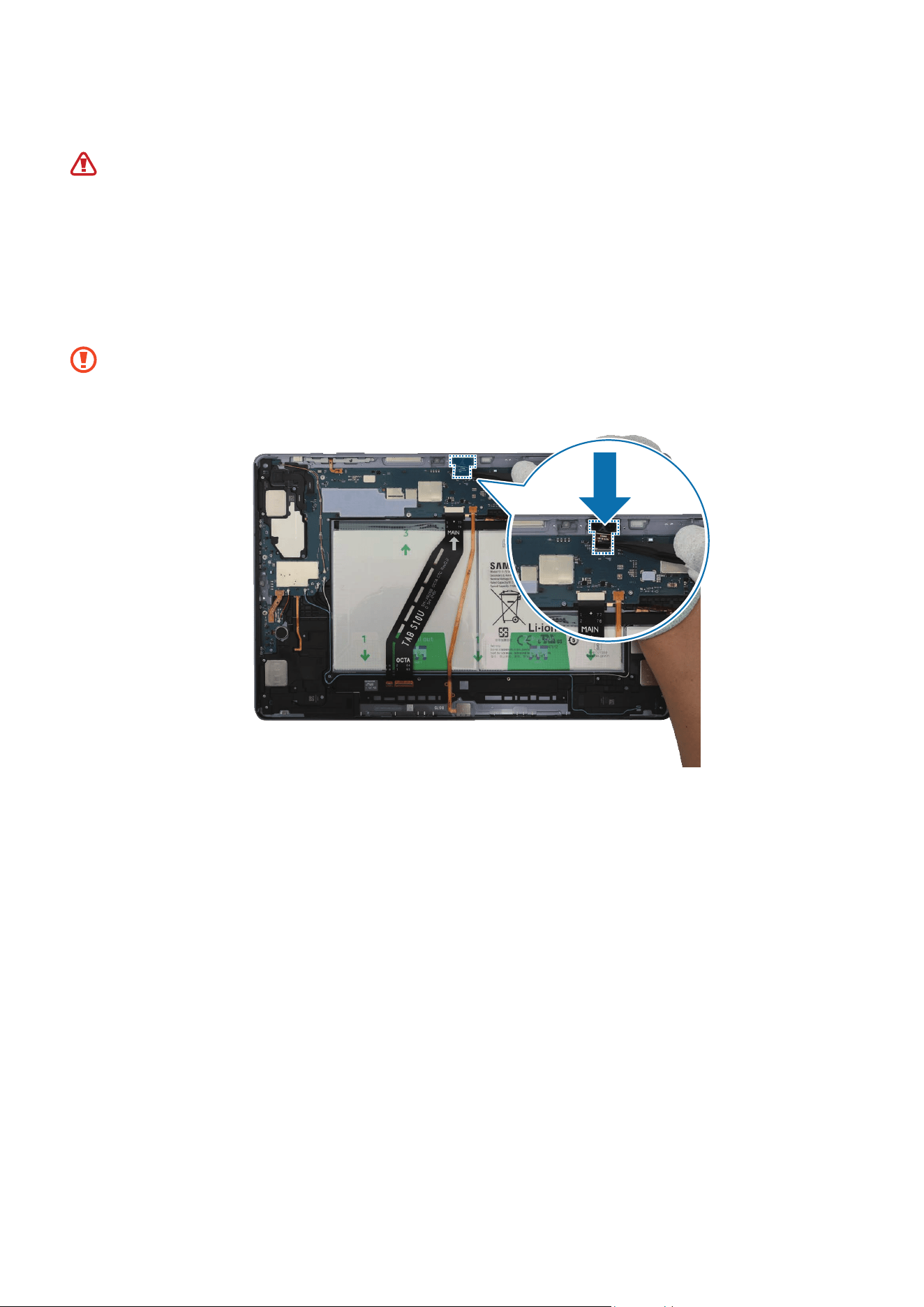
1 Using the tweezers, remove all release films from the new front camera module.
Using the tweezers or your fingers, place the front camera in the camera hole so that
the lens faces upward, and gently insert the front camera.
•
Be careful not to damage the camera lens and near components.
•
Be careful not to damage and scratch the camera module.
Disassembly and Assembly
132
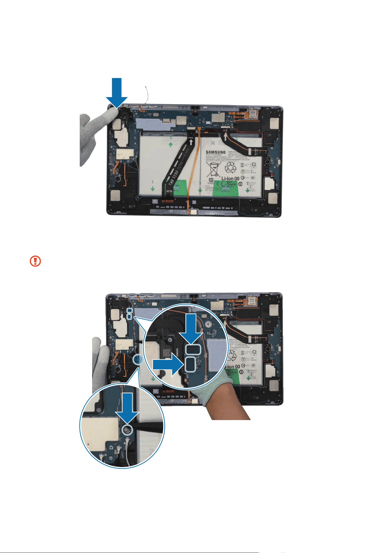
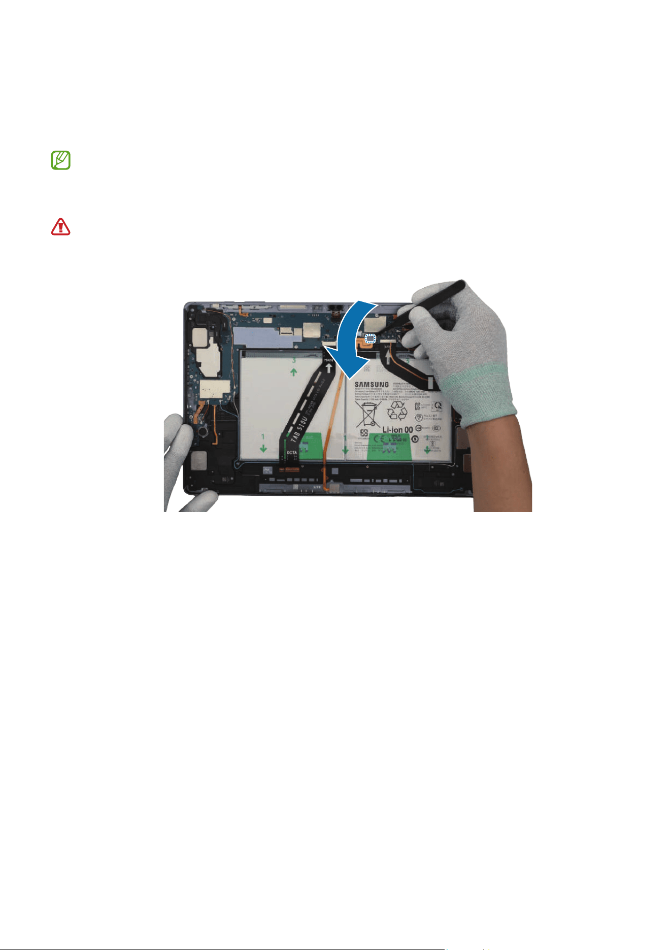
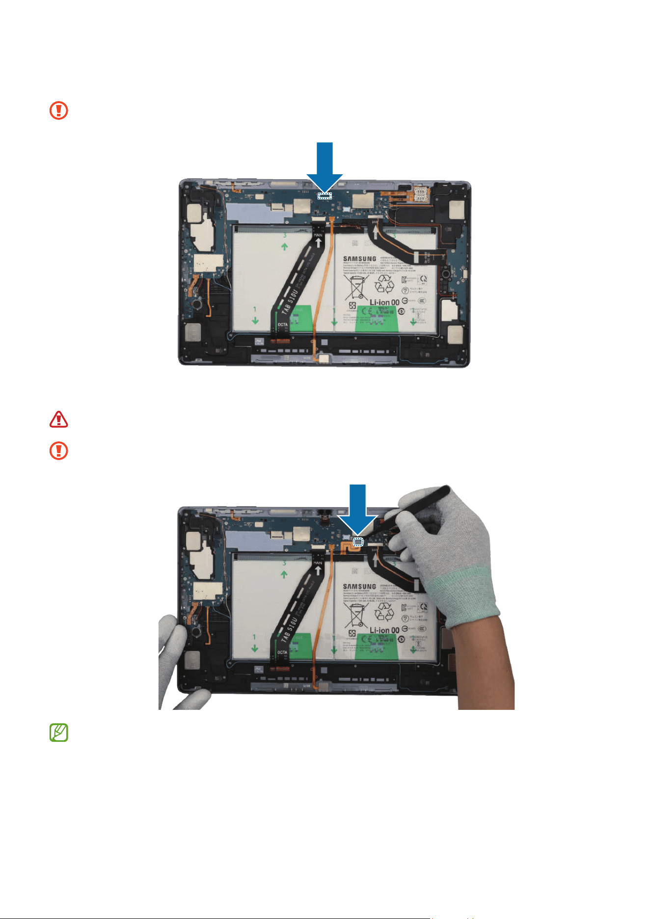
2 Using the tweezers, connect the front camera connector carefully to the main board.
Be careful not to damage the front camera and near components.
3 Using the tweezers, connect the battery connector to the main board.
Be careful not to damage the battery.
Be careful not to damage the battery connector and near components.
Reassemble the Bracket and Screen to complete assembly.

Disassembly and Assembly
133
Speaker 1
Disassembly
Remove the Screen and Bracket first before you begin.
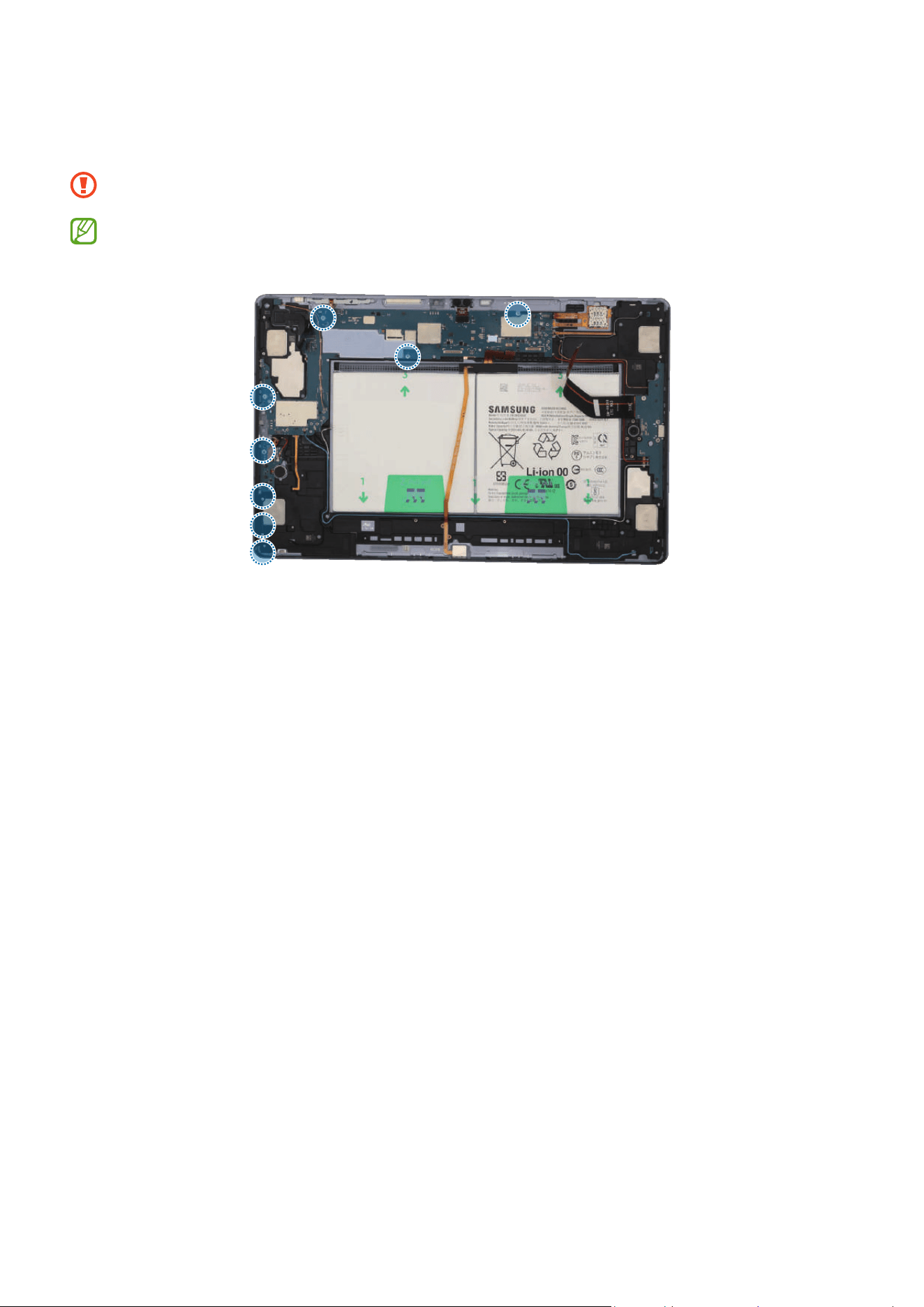
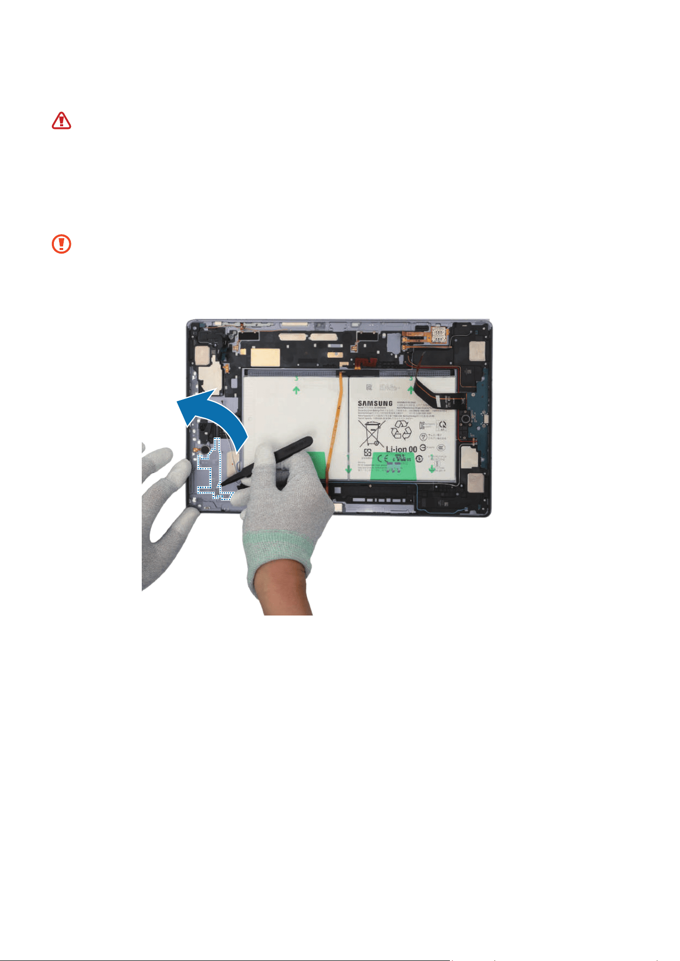
1 Using the tweezers, disconnect the battery connector from the main board first.
Separate the 8 connectors and the 3 coaxial cable connectors (Orange/Black/Red)
from the main board. For the 5G or LTE devices, separate the additional 5 coaxial
cable connectors (Blue/White/Grey/Orange/Red).
•
Make sure to first disconnect the battery connector for your own safety.
•
Be careful not to damage the battery.
•
Be careful not to damage the cable while removing the connector.
•
Be careful not to damage the near components.
•
The 5 coaxial cables (Blue/White/Grey/Orange/Red) are only available for the
5G or LTE devices.
•
The cables and connectors may vary depending on the country, region, or
specifications.
Disassembly and Assembly
134

Disassembly and Assembly
135
Coaxial cable
(White)
Coaxial cable
(Blue)
Coaxial cable
(Grey)
Coaxial cable (Red)
Coaxial cable
(Orange)
Disassembly and Assembly
136
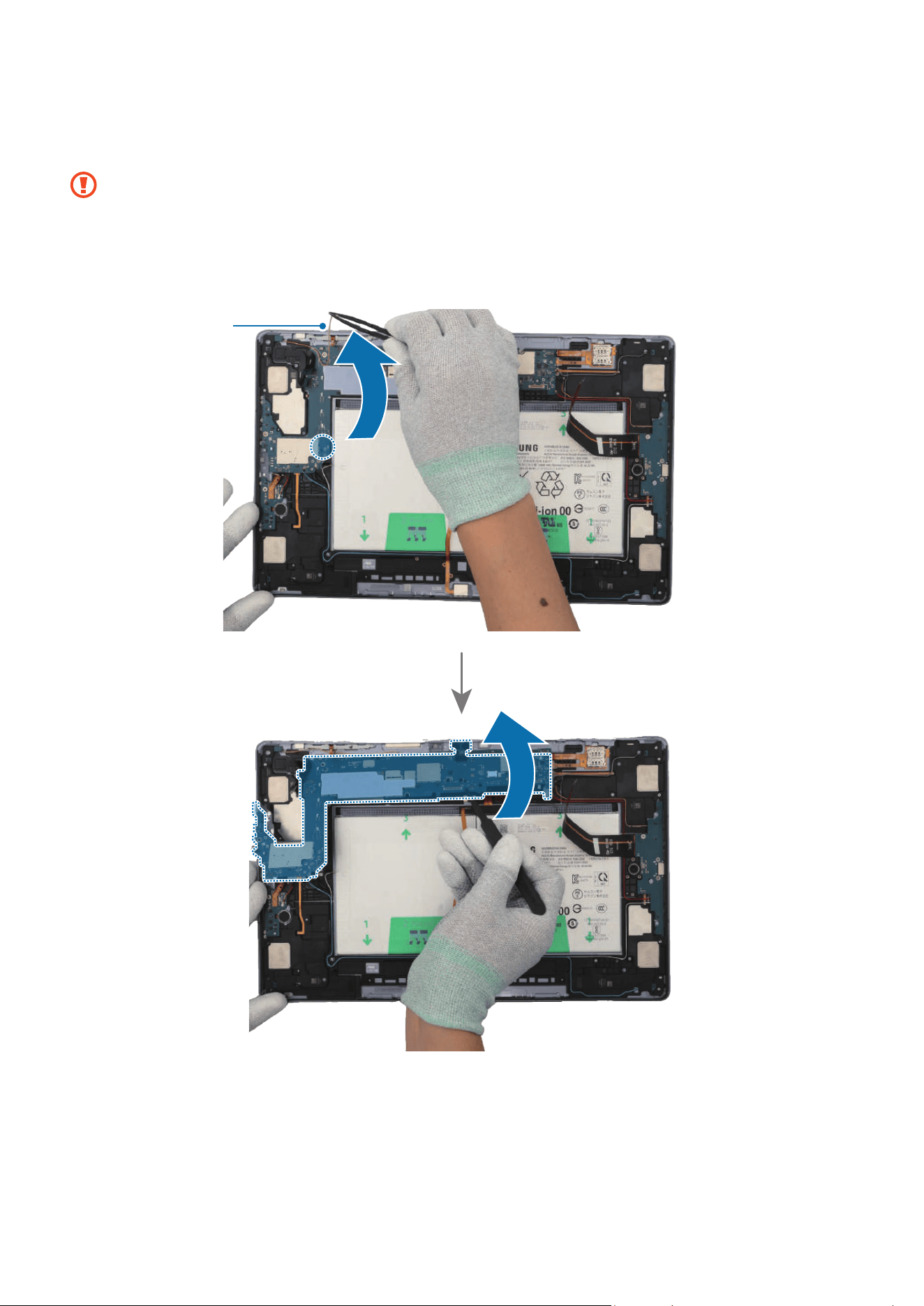
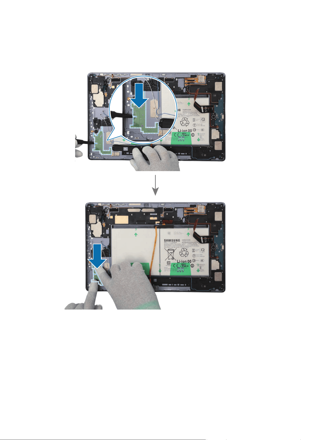
2 Check the 4 screws on the main board, the screw on the Wi-Fi board, and the 3 screws
on the speaker. Remove all 8 screws using a cross-head screwdriver.
Be careful not to damage the main board and near components.
Check the number of screws that have been removed, and store them carefully to
make sure that no unassembled screws are left inside the device during assembly.
Disassembly and Assembly
137
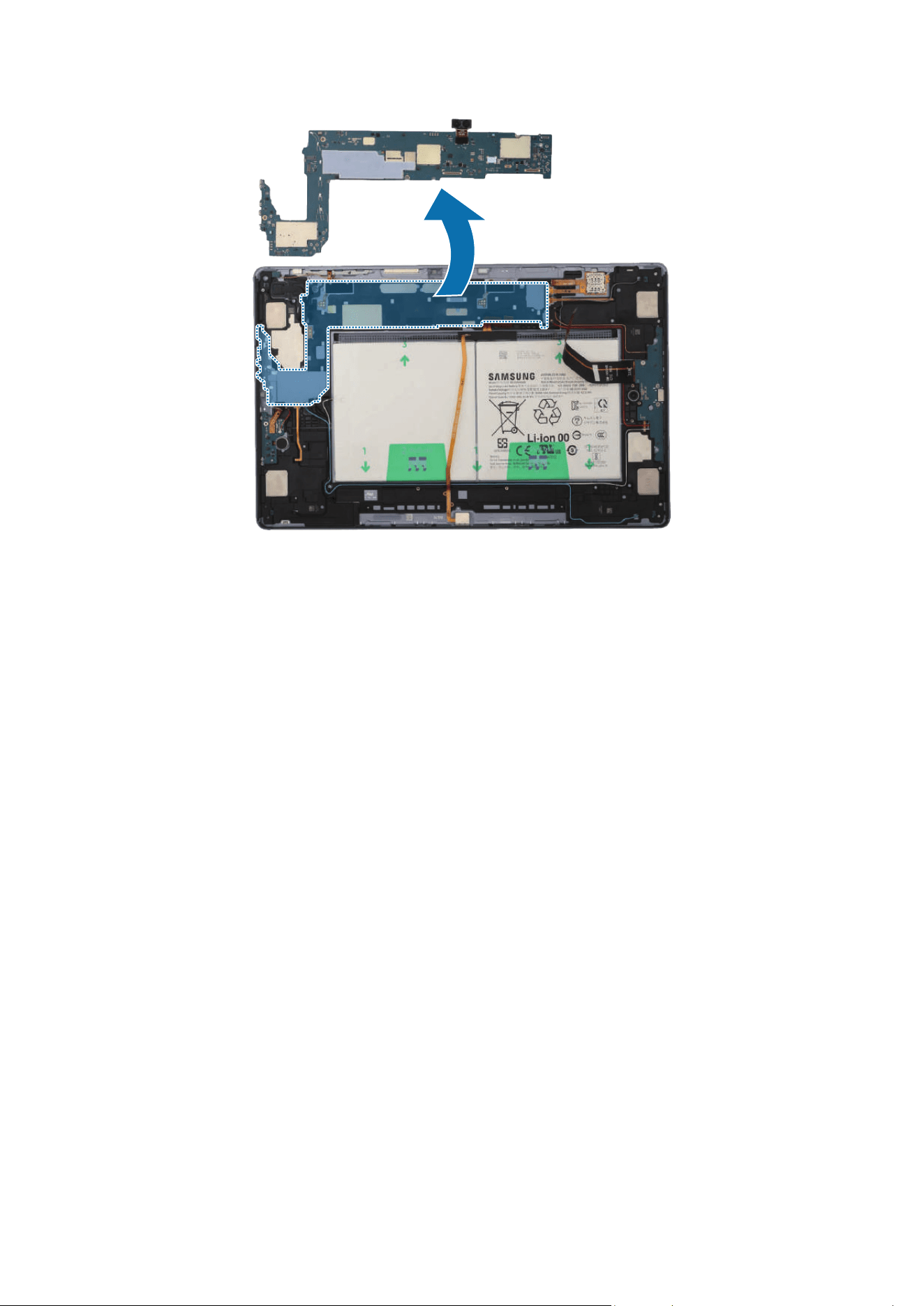
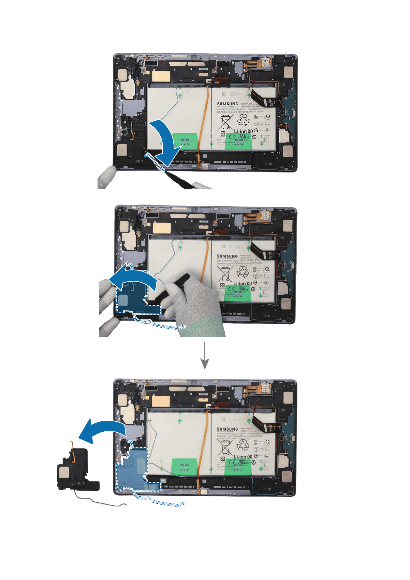
3 Using the tweezers, disconnect the coaxial cable (Orange) from the main board. Then,
lift up on the separator groove of the main board and remove the main board module.
•
Be careful not to damage the battery connector, the main board, and near
components.
•
The cables have to positioned outside so as not to interfere when disassembling
the main board.
Coaxial cable
(Orange)
Disassembly and Assembly
138
Disassembly and Assembly
139
4 Using the tweezers, lift up the Wi-Fi board from the back cover module and remove it.
Disassembly and Assembly
140
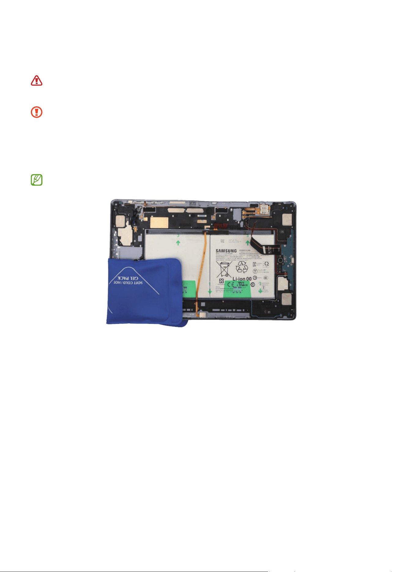
5 Heat the microwaveable heating bag and apply it to the both front and back side of
the speaker module for 4 minutes.
•
It is possible for the device or battery to be damaged by heat.
•
Do not heat the device in a microwave. Doing so could cause an explosion.
•
Follow the heating bag’s instructions for heating. The recommended time for
heating the bag is 50 seconds in a 1000 W microwave and 70 seconds in a 700 W
microwave. (Correct temperature for use: 55-65 ℃.)
•
Be careful not to damage the device through excessive heat. (It is
recommended to disassemble the device in an area with a temperature gauge.)
When reheating, it should be heated no longer than 30 seconds.
Disassembly and Assembly
141
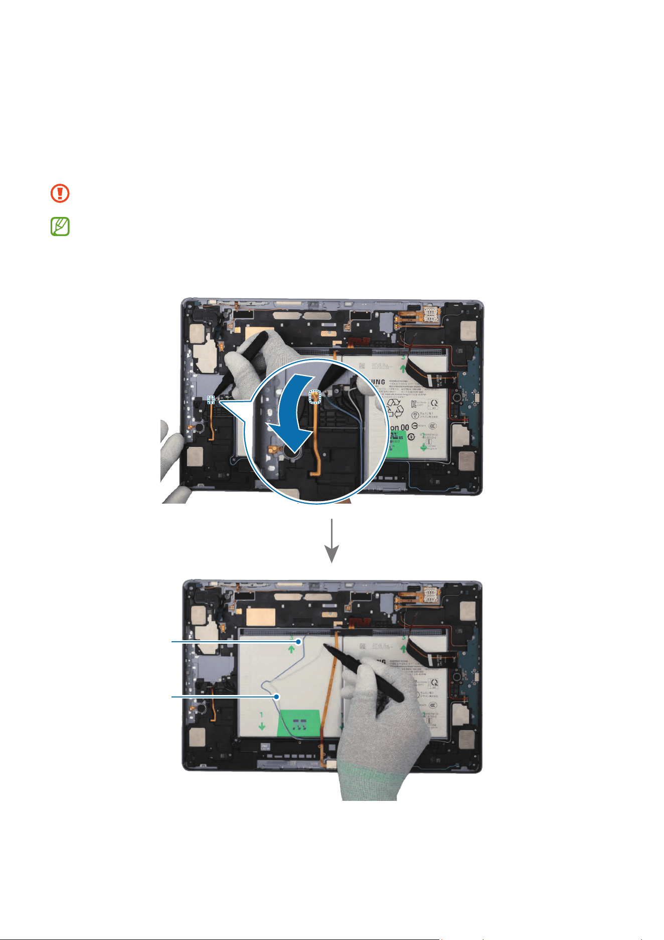
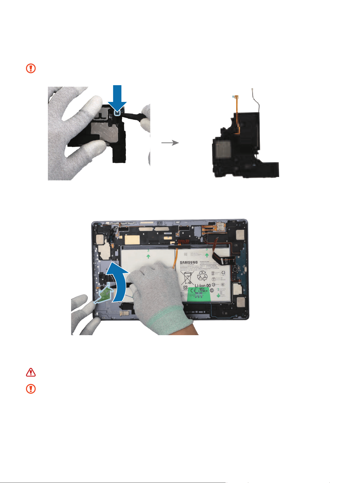
6 Using the tweezers, separate the FPCB of the speaker module carefully. For the
5G or LTE devices, separate the 2 additional coaxial cables (Blue/White). Using
the tweezers, separate the coaxial cable (Black) in the speaker module. Insert the
tweezers into the separator groove of the speaker and remove it from the back cover
module.
Be careful not to damage the cables and near components.
•
The 2 coaxial cables (Blue/White) are only available for the 5G or LTE devices.
•
The cables and connectors may vary depending on the country, region, or
specifications.
Coaxial cable
(Blue)
Coaxial cable
(White)
Disassembly and Assembly
142
Disassembly and Assembly
143
7 Using the tweezers, separate the coaxial cable connector (Black) from the speaker
module.
Be careful not to damage the cable.
Disassembly and Assembly
144
Reassembly
Leaving screws inside the device may damage internal components, such as the
battery. During assembly, be extra careful not to leave any unassembled screws
inside the device.
1 Using the tweezers and your fingers, remove all adhesive tapes from where the
speaker was attached.
•
Make sure to remove any residual tapes attached to the position of the
separated speaker before reassembling the new speaker.
•
Be careful not to damage the near components.
Disassembly and Assembly
145
2 Using the tweezers, remove the release film of a new speaker 1 adhesive tape (1 ea).
Align the outside shape of the tape with the speaker position and attach it accurately.
Gently press down the tape with your fingers so that the tape can be attached well.
Disassembly and Assembly
146
3 Using the tweezers, connect the coaxial cable connector (Black) to the new speaker
module.
Be careful not to damage the speaker and cable.
4 Using the tweezers, hold the protruding release film of the attached tape and
carefully remove it.
5 Using the tweezers or your fingers, remove the release film of the new speaker. Place
the speaker module to the exact position, and assemble it to the back cover module.
Be careful not to damage the battery.
•
The cables have to positioned outside so as not to interfere when assembling
the speaker.
•
Be careful not to damage the speaker and cable.
•
Be careful not to damage the near components.
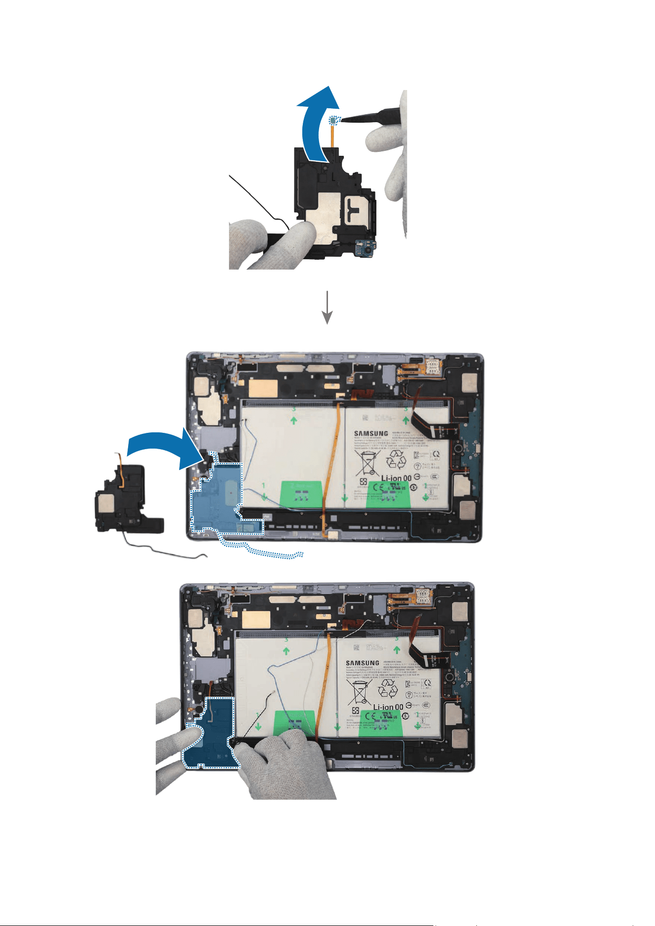
Disassembly and Assembly
147
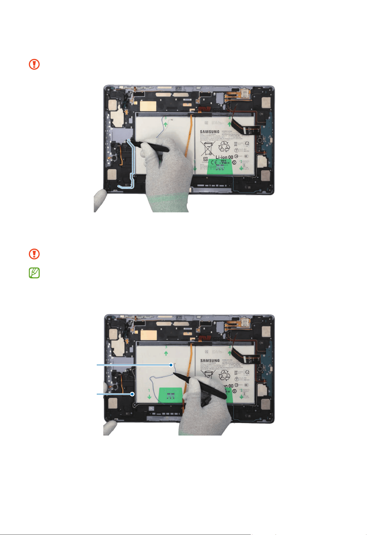
Disassembly and Assembly
148
6 Using the tweezers, assemble the coaxial cable (Black) to the speaker module.
Be careful not to damage the speaker and cable.
7 For the 5G or LTE devices, assemble the coaxial cables (White/Blue) to the speaker
module.
Be careful not to damage the cables and near components.
•
The 2 coaxial cables (White/Blue) are only available for the 5G or LTE devices.
•
The cables and connectors may vary depending on the country, region, or
specifications.
Coaxial cable
(Blue)
Coaxial cable
(White)
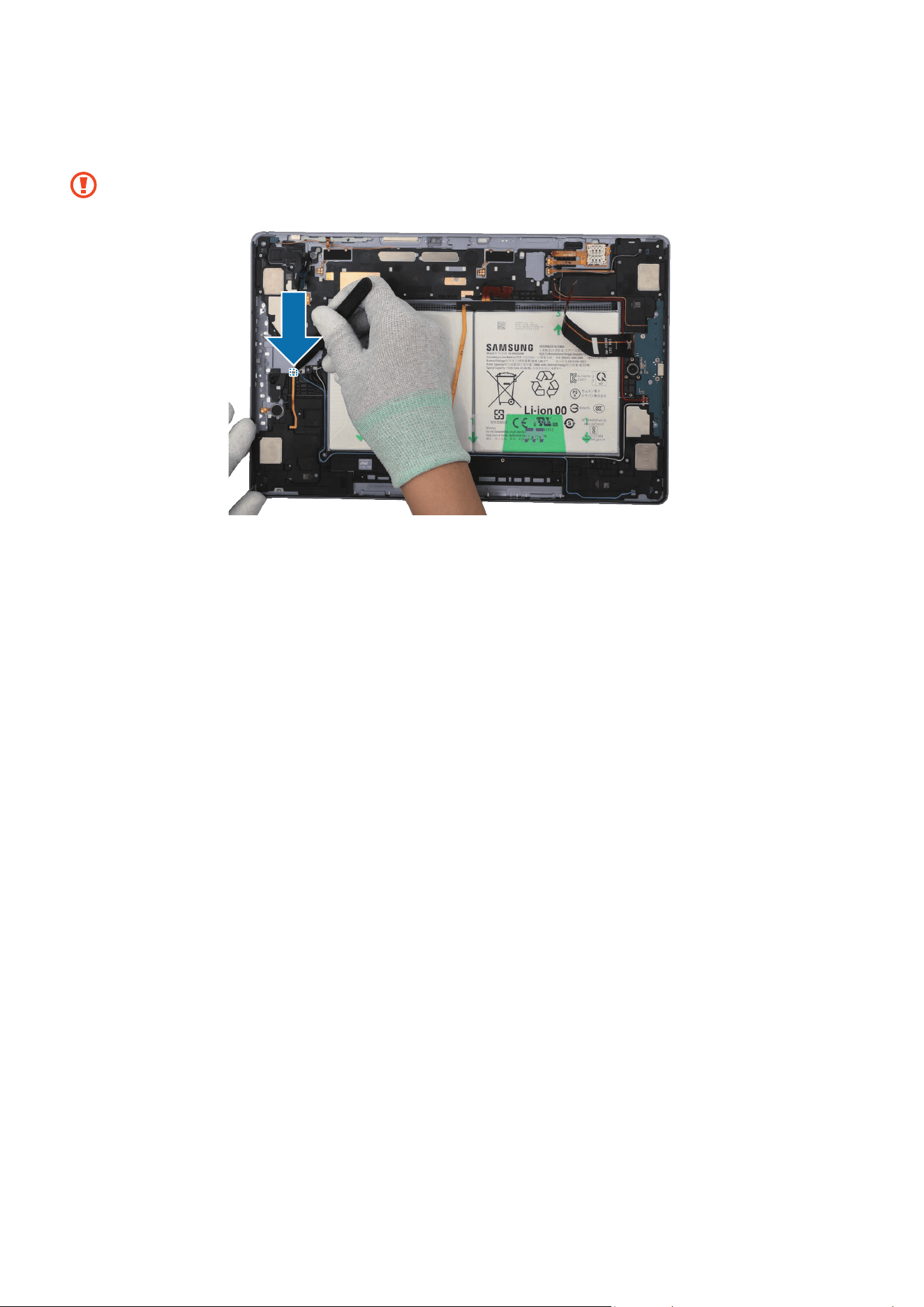
Disassembly and Assembly
149
8 Using your fingers, press down softly and evenly on the speaker module and the FPCB
so that the speaker module can be completely attached.
Be careful not to damage speaker and FPCB.
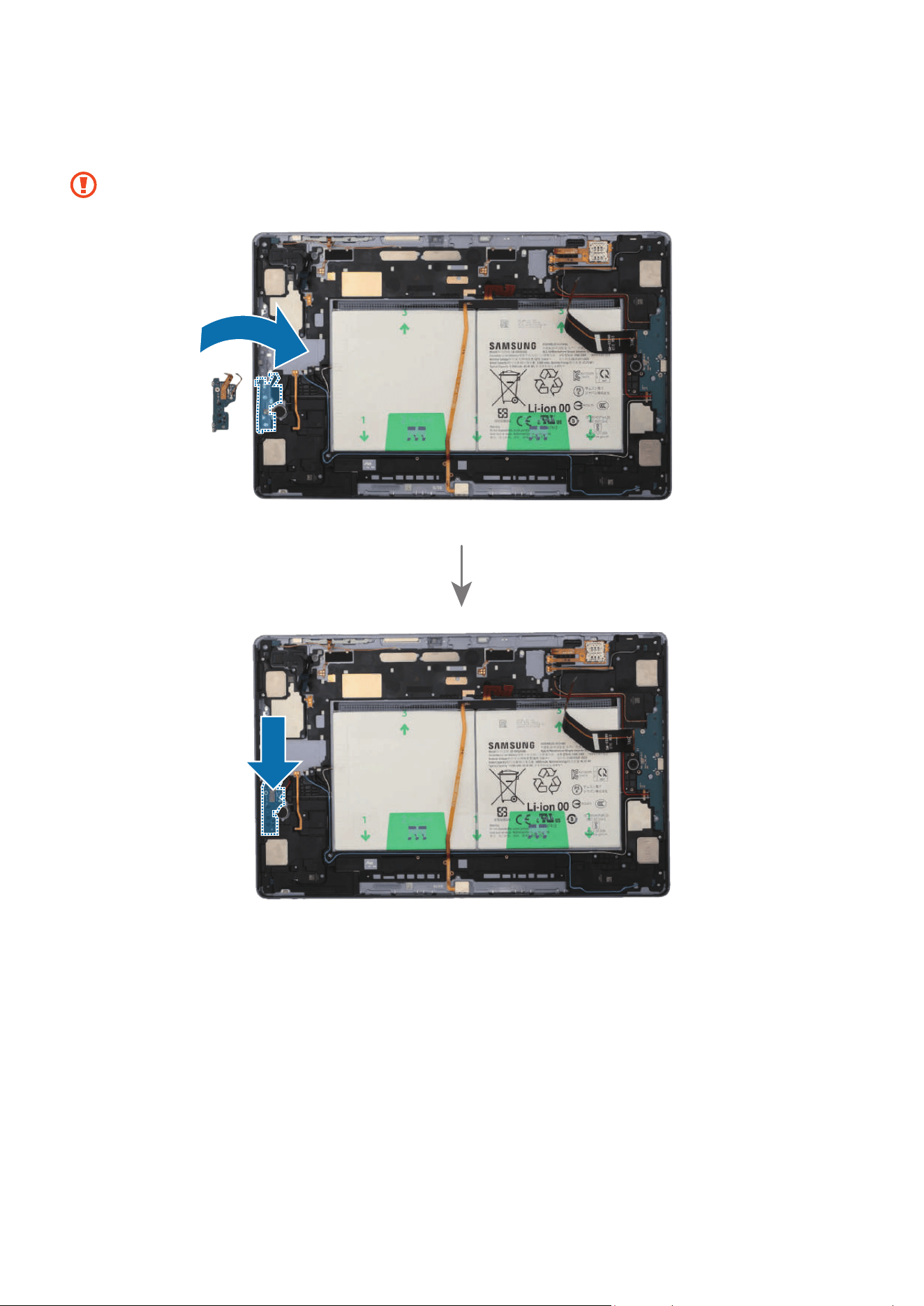
Disassembly and Assembly
150
9 Using the tweezers, place the Wi-Fi board to the exact position, and assemble it to the
back cover module.
Be careful not to damage the Wi-Fi board and near components.
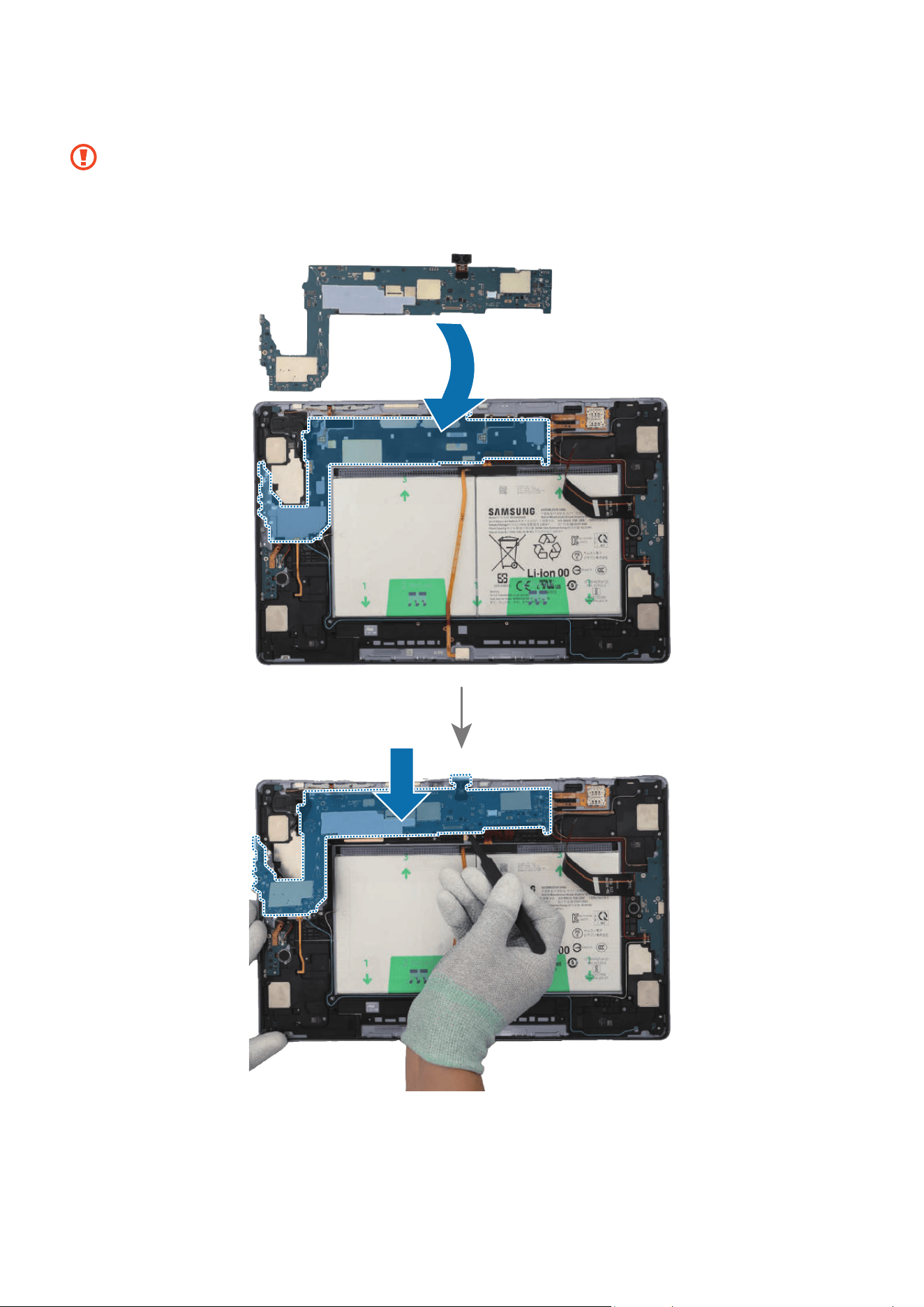
Disassembly and Assembly
151
10
Place the main board to the exact position, and assemble it to the back cover module.
•
The cables have to positioned outside so as not to interfere when assembling
the main board.
•
Be careful not to damage the main board and near components.
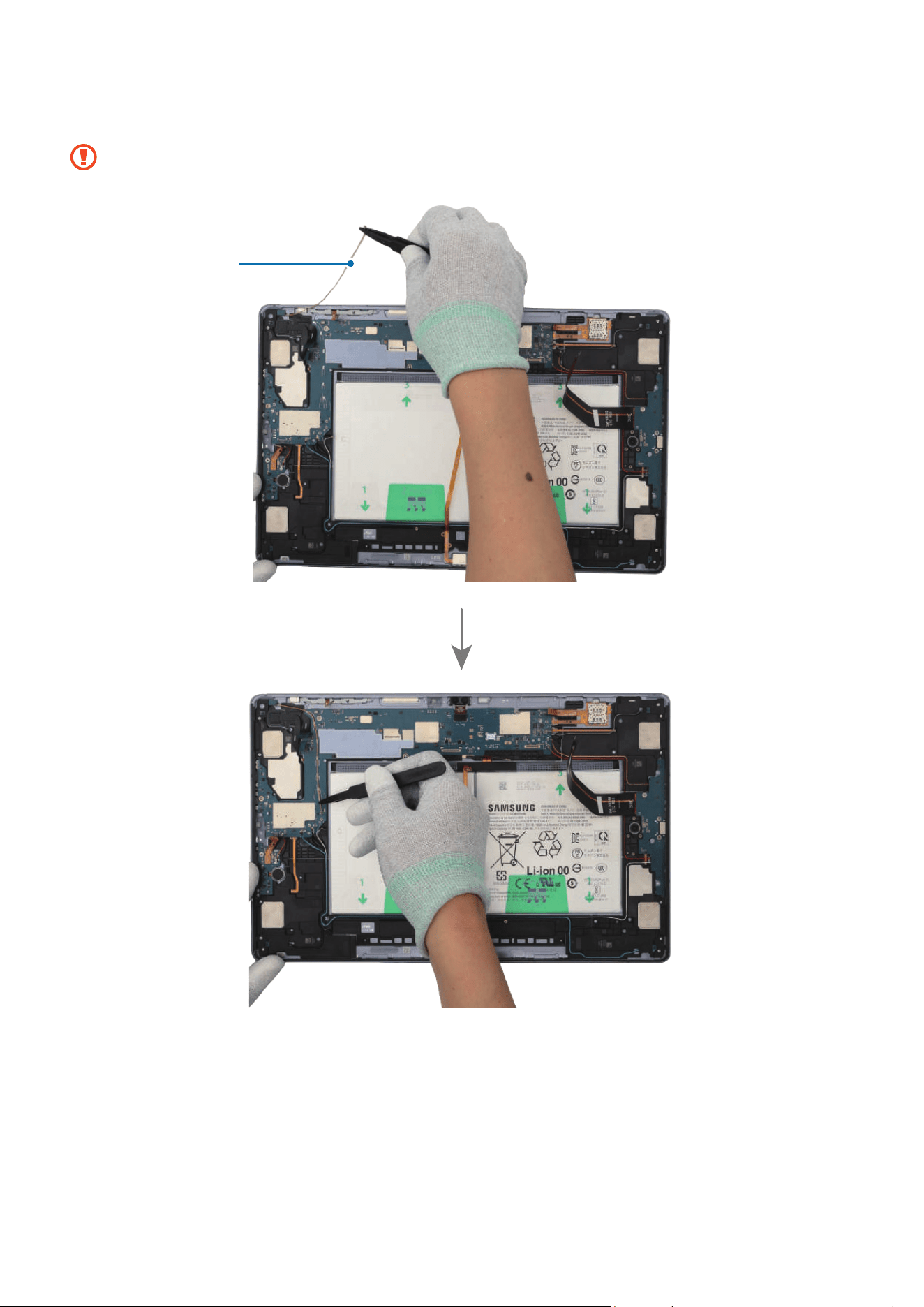
Disassembly and Assembly
152
11
Using the tweezers, connect the coaxial cable (Orange) to the main board.
Be careful not to damage the cables and near components.
Coaxial cable
(Orange)
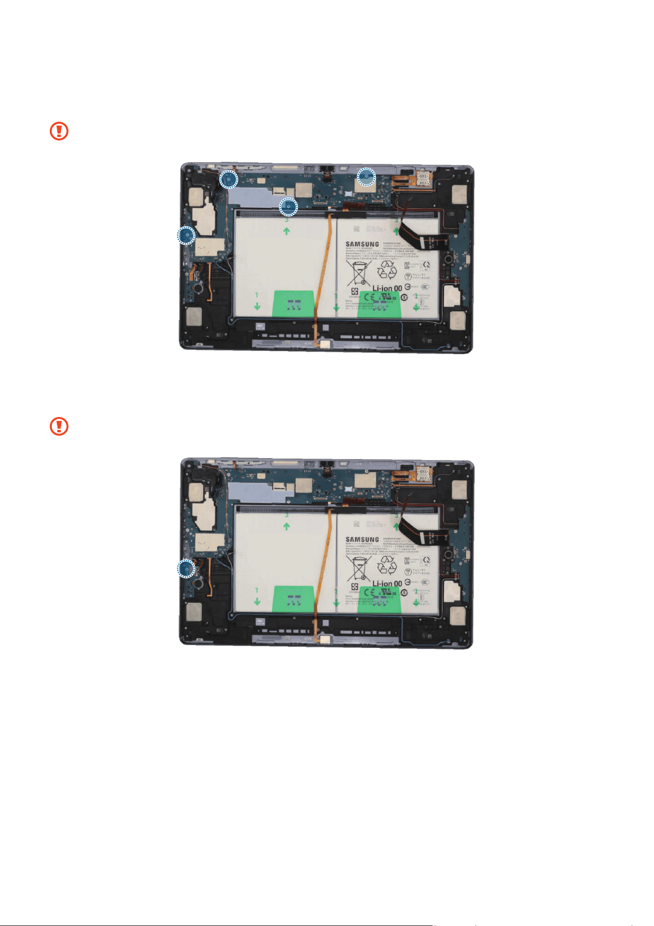
Disassembly and Assembly
153
12
Check the screw 3463 (4 ea) and fasten them on the main board using a cross-head
screwdriver.
Be careful not to damage the main board and near components.
13
Check the screw 3443 (1 ea) and fasten it on the Wi-Fi board using a cross-head
screwdriver.
Be careful not to damage the Wi-Fi board and near components.
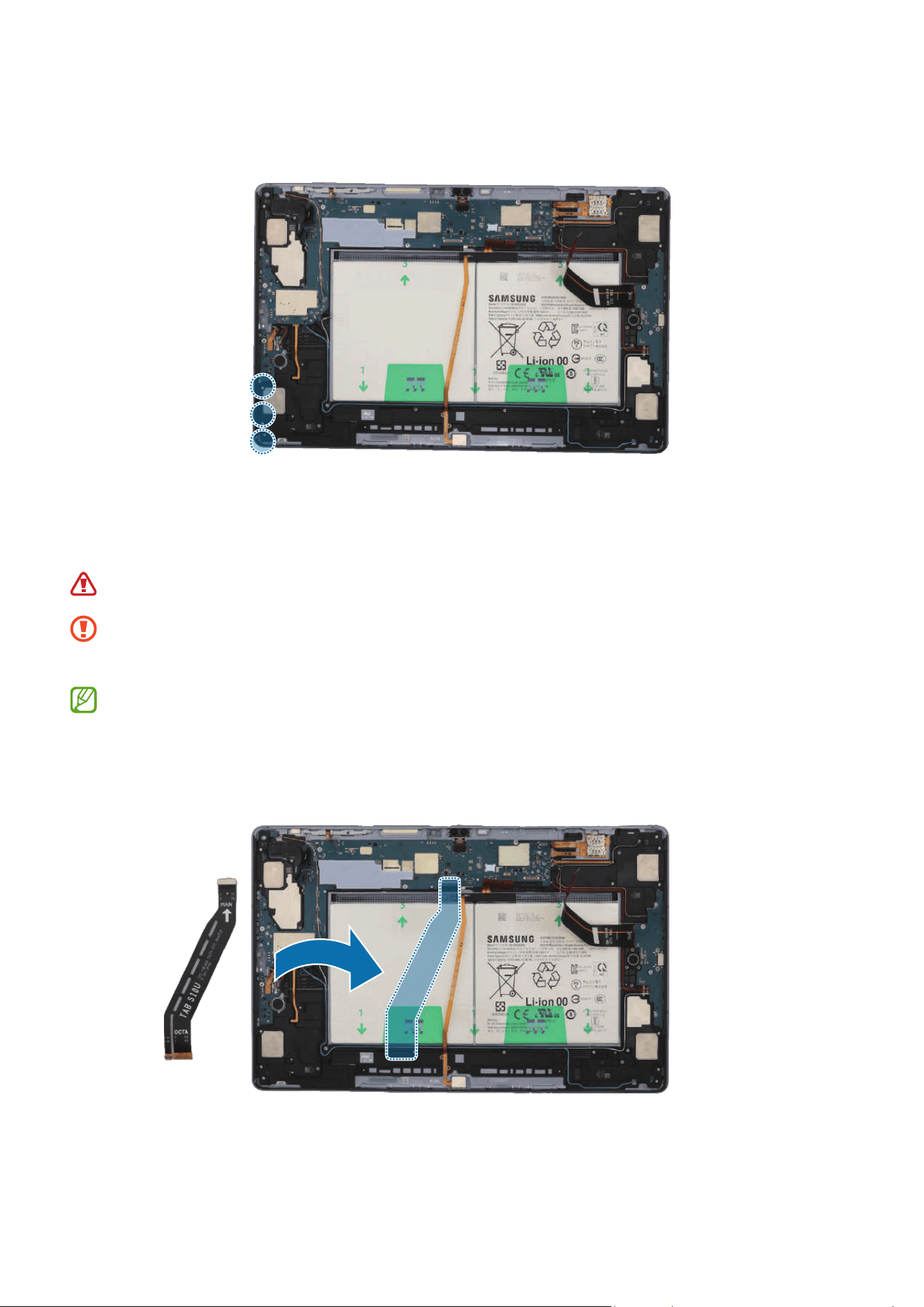
Disassembly and Assembly
154
14
Check the screw 3405 (3 ea) and fasten them on the speaker using a cross-head
screwdriver.
15
Using the tweezers, connect the 8 connectors and the 3 coaxial cable connectors
(Orange/Black/Red) to the main board. For the 5G or LTE devices, connect the
additional 5 coaxial cable connectors (Blue/White/Grey/Orange/Red).
Be careful not to damage the battery.
•
Be careful not to damage the cable while connecting the connector.
•
Be careful not to damage the near components.
•
The 5 coaxial cables (Blue/White/Grey/Orange/Red) are only available for the
5G or LTE devices.
•
The cables and connectors may vary depending on the country, region, or
specifications.

Disassembly and Assembly
155
Coaxial cable
(White)
Coaxial cable
(Blue)
Coaxial cable
(Grey)
Coaxial cable (Red)
Coaxial cable
(Orange)
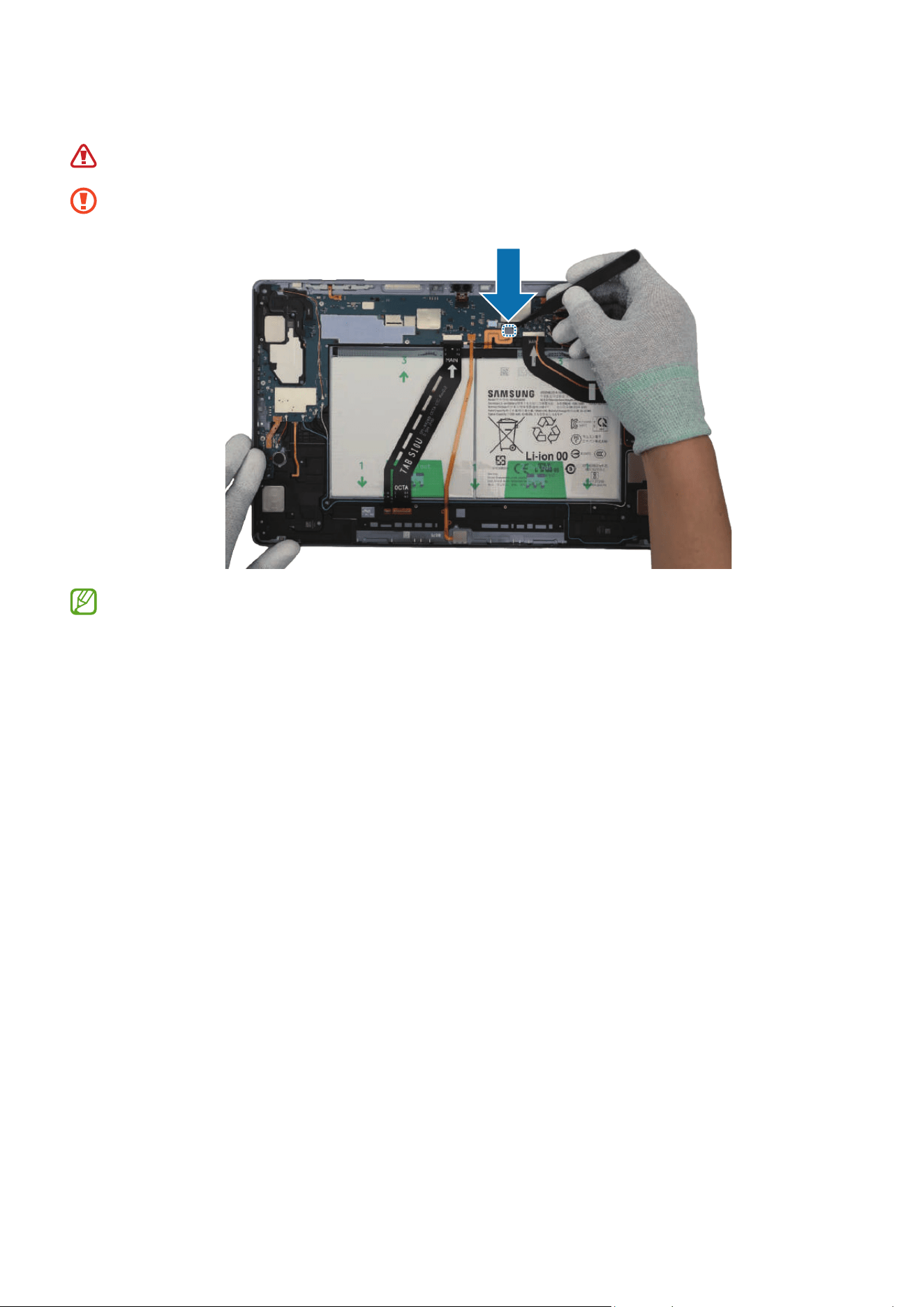

Disassembly and Assembly
157
Speaker 2
Disassembly
Remove the Screen and Bracket first before you begin.
1 Using the tweezers, disconnect the battery connector from the main board first.
Separate the 8 connectors and the 3 coaxial cable connectors (Orange/Black/Red)
from the main board. For the 5G or LTE devices, separate the additional 5 coaxial
cable connectors (Blue/White/Grey/Orange/Red).
•
Make sure to first disconnect the battery connector for your own safety.
•
Be careful not to damage the battery.
•
Be careful not to damage the cable while removing the connector.
•
Be careful not to damage the near components.
•
The 5 coaxial cables (Blue/White/Grey/Orange/Red) are only available for the
5G or LTE devices.
•
The cables and connectors may vary depending on the country, region, or
specifications.

Disassembly and Assembly
158
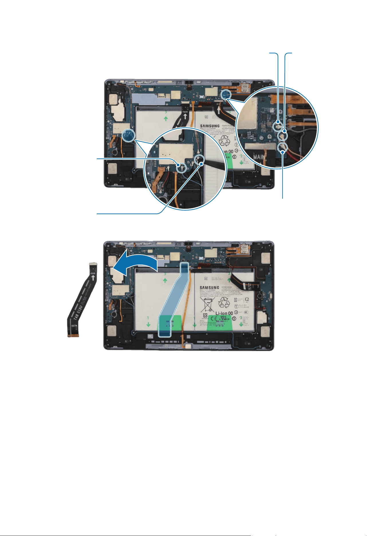
Disassembly and Assembly
159
Coaxial cable
(White)
Coaxial cable
(Blue)
Coaxial cable
(Grey)
Coaxial cable (Red)
Coaxial cable
(Orange)
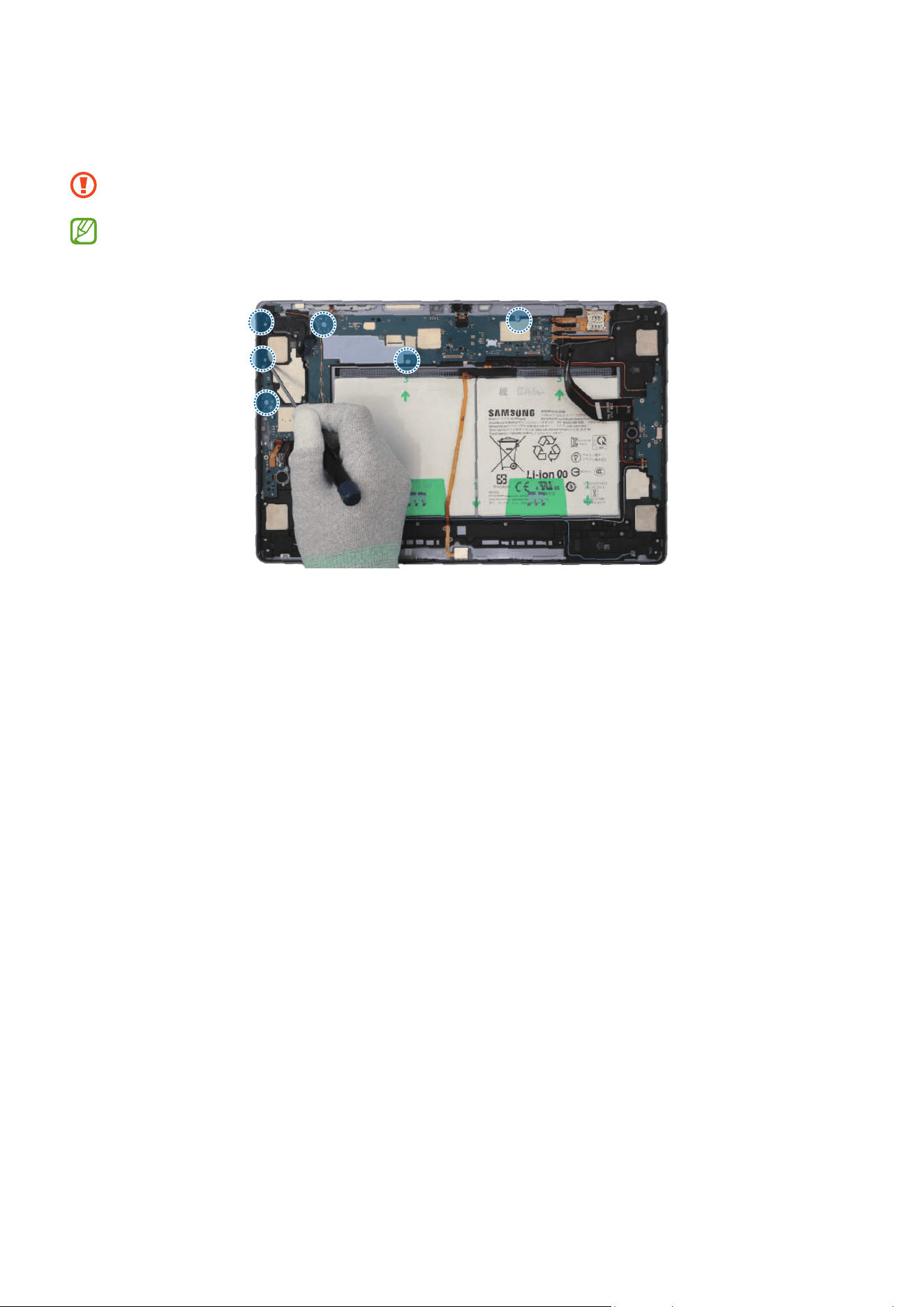
Disassembly and Assembly
160
2 Check the 4 screws on the main board and the 2 screws on the speaker. Remove all
6 screws using a cross-head screwdriver.
Be careful not to damage the main board and near components.
Check the number of screws that have been removed, and store them carefully to
make sure that no unassembled screws are left inside the device during assembly.
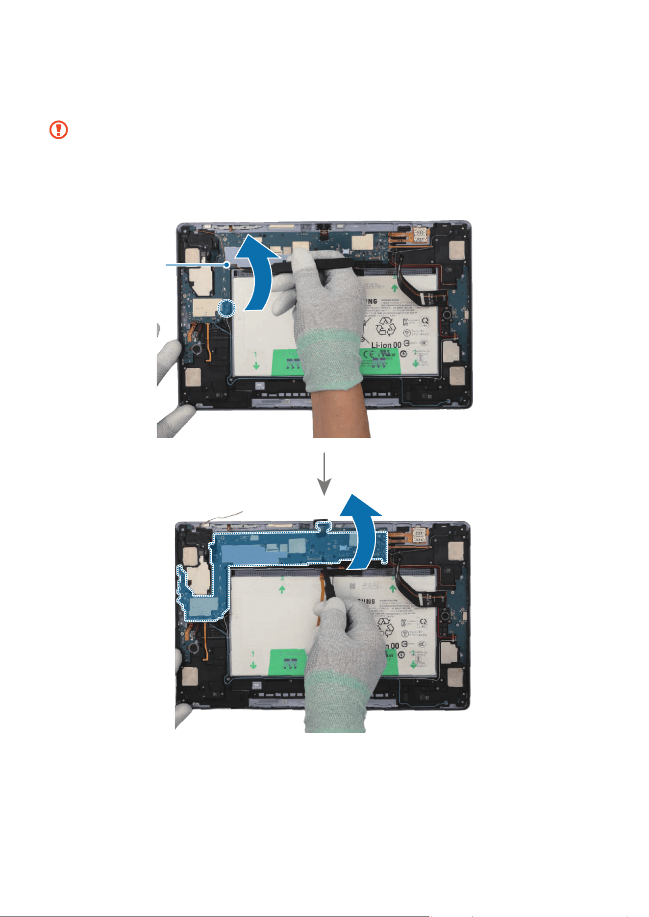
Disassembly and Assembly
161
3 Using the tweezers, disconnect the coaxial cable (Orange) from the main board. Then,
lift up on the separator groove of the main board and remove the main board module.
•
Be careful not to damage the battery connector, the main board, and near
components.
•
The cables have to positioned outside so as not to interfere when disassembling
the main board.
Coaxial cable
(Orange)
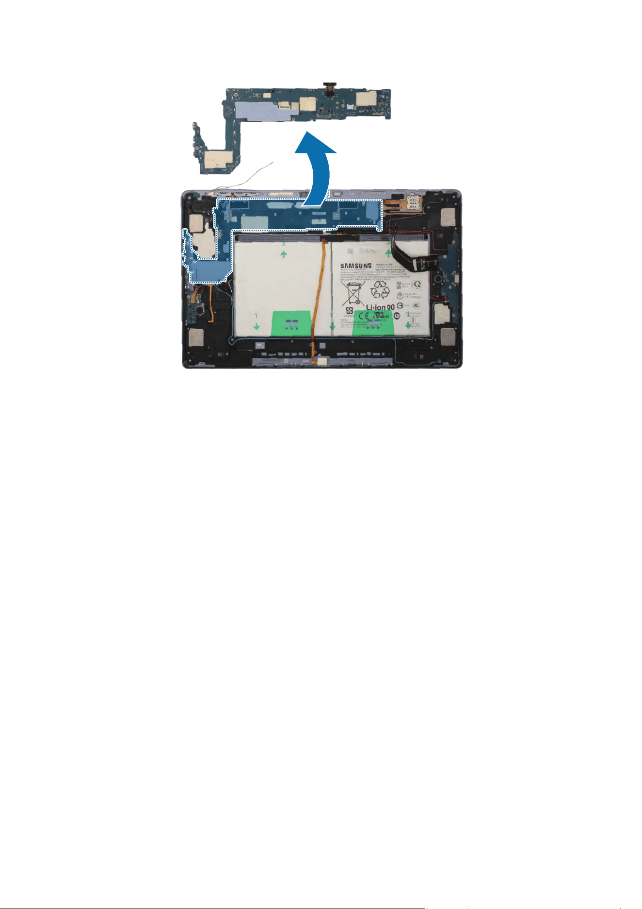
Disassembly and Assembly
162
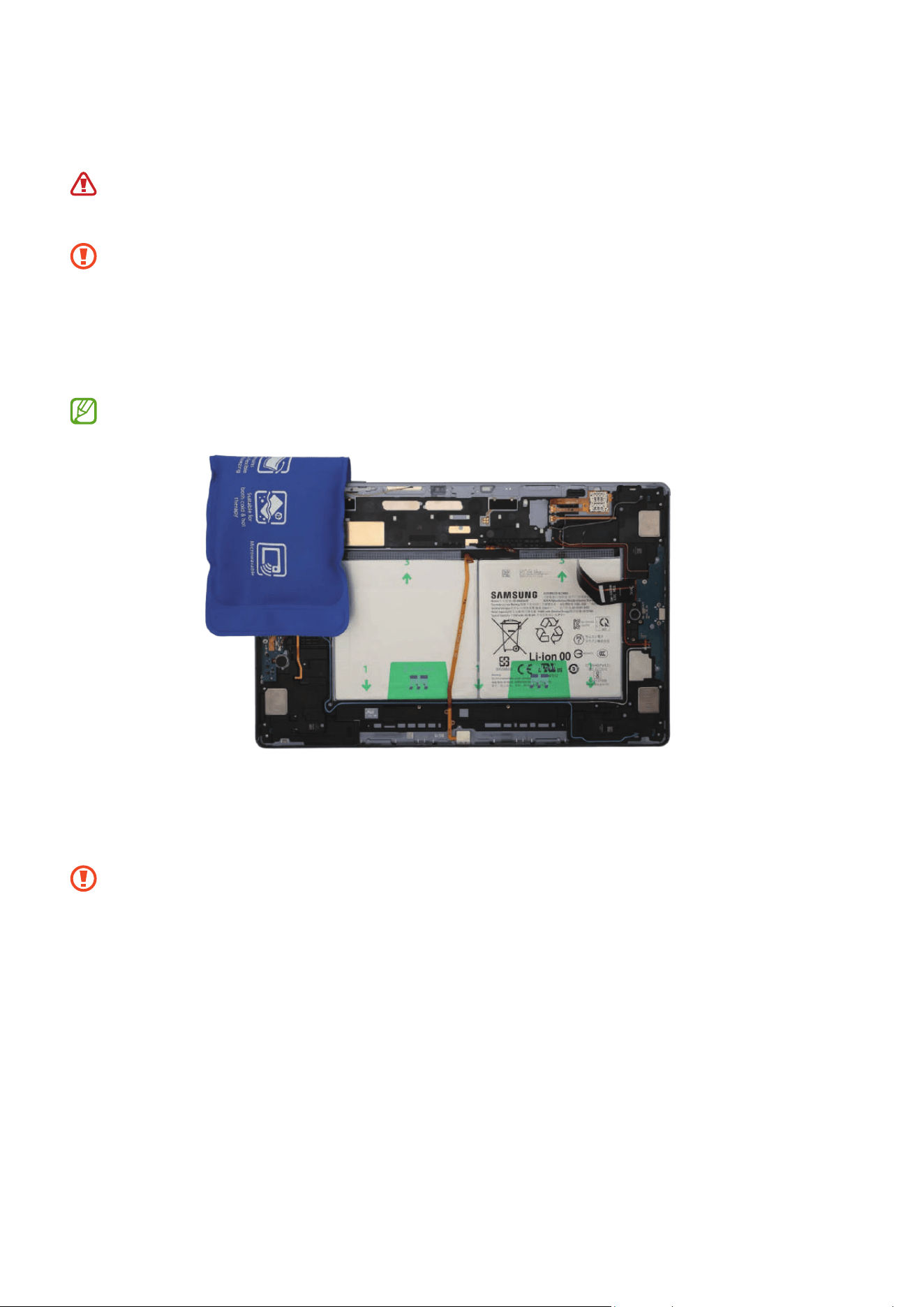
Disassembly and Assembly
163
4 Heat the microwaveable heating bag and apply it to the both front and back side of
the speaker module for 4 minutes.
•
It is possible for the device or battery to be damaged by heat.
•
Do not heat the device in a microwave. Doing so could cause an explosion.
•
Follow the heating bag’s instructions for heating. The recommended time for
heating the bag is 50 seconds in a 1000 W microwave and 70 seconds in a 700 W
microwave. (Correct temperature for use: 55-65 ℃.)
•
Be careful not to damage the device through excessive heat. (It is
recommended to disassemble the device in an area with a temperature gauge.)
When reheating, it should be heated no longer than 30 seconds.
5 Using the tweezers, separate the FPCB of the speaker module carefully. Insert the
tweezers into the separator groove of the speaker and remove it from the back cover
module.
Be careful not to damage the cables and near components.
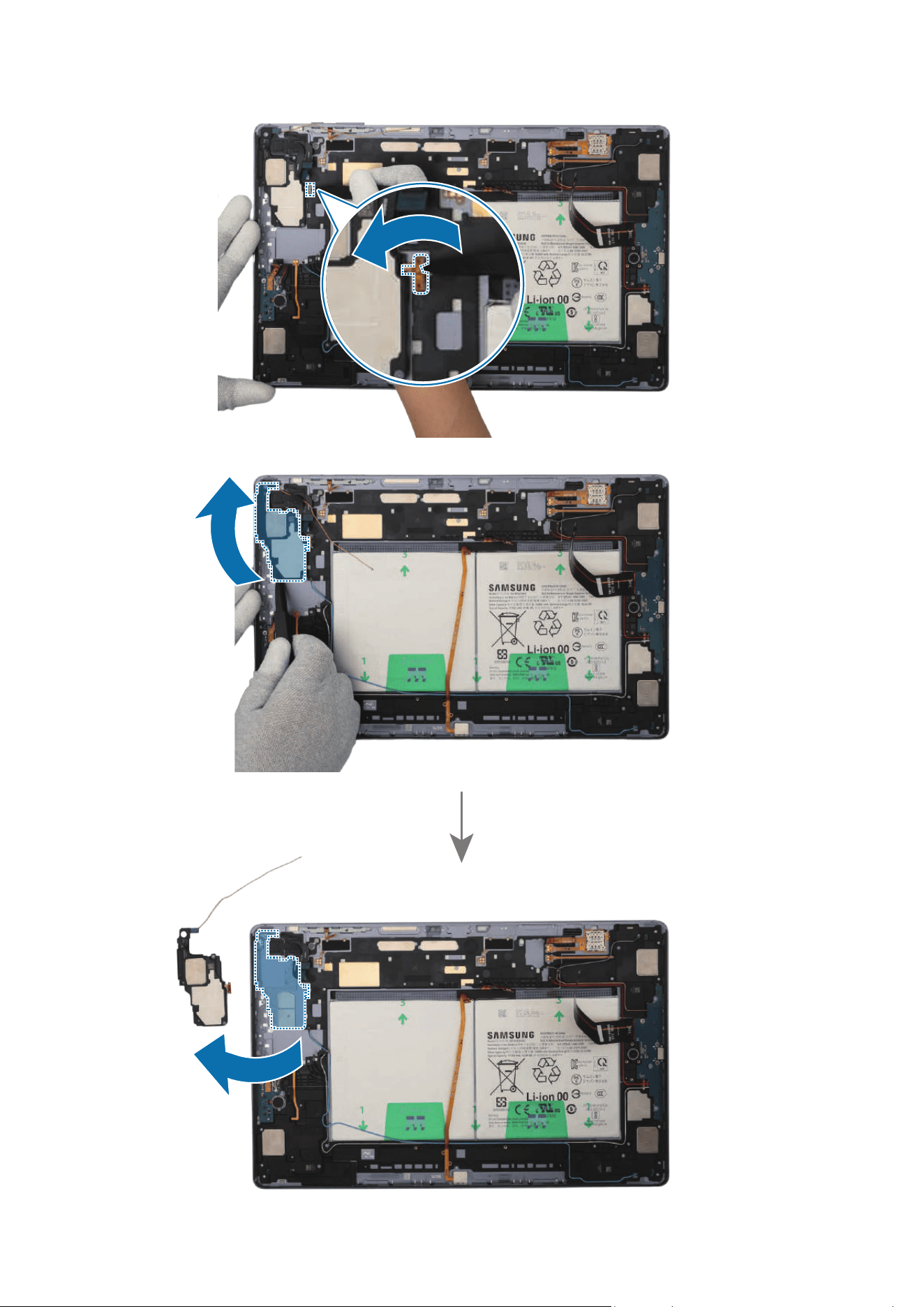
Disassembly and Assembly
164
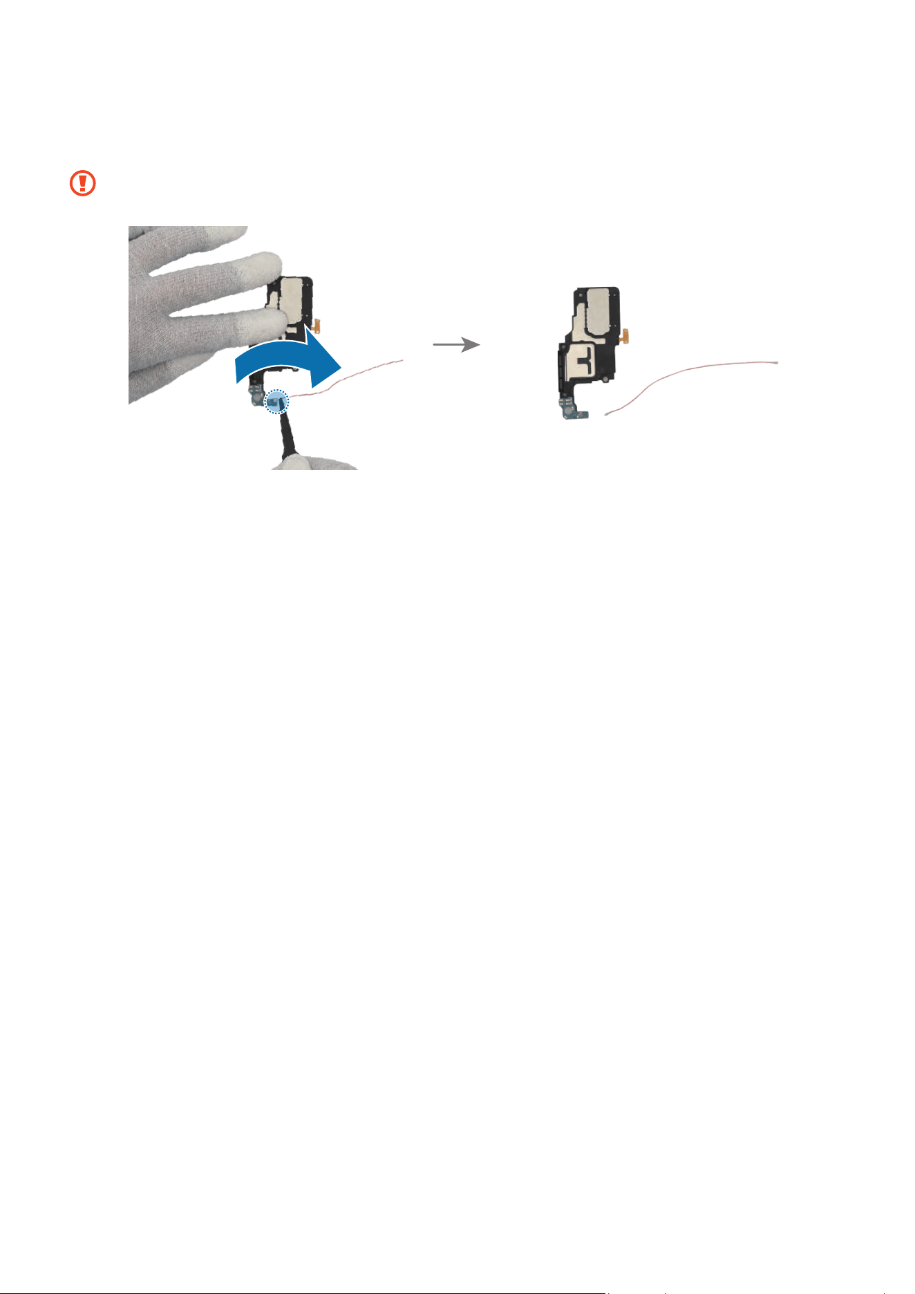
Disassembly and Assembly
165
6 Using the tweezers, separate the coaxial cable connector (Orange) from the speaker
module.
Be careful not to damage the cable.
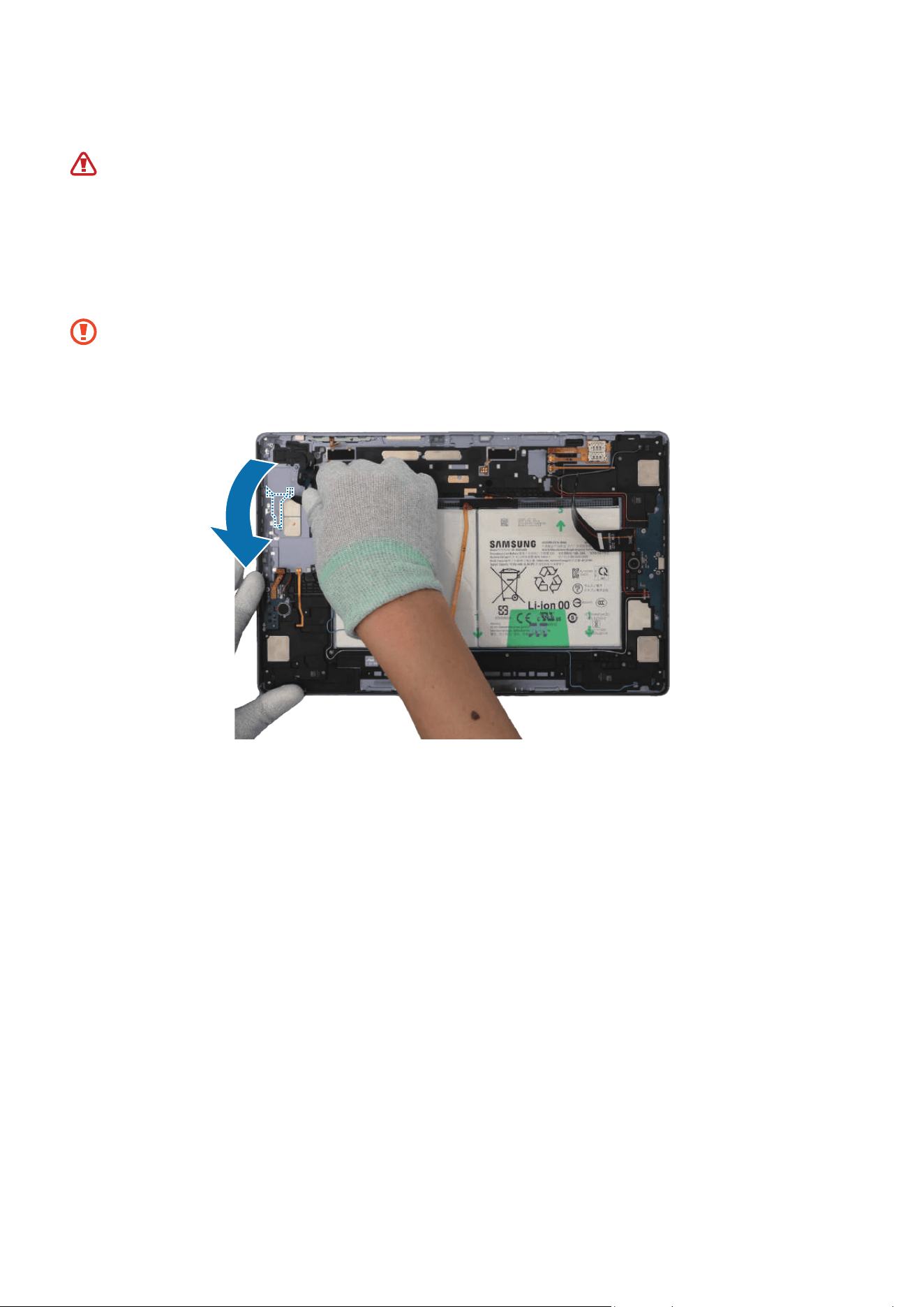
Disassembly and Assembly
166
Reassembly
Leaving screws inside the device may damage internal components, such as the
battery. During assembly, be extra careful not to leave any unassembled screws
inside the device.
1 Using the tweezers and your fingers, remove all adhesive tapes from where the
speaker was attached.
•
Make sure to remove any residual tapes attached to the position of the
separated speaker before reassembling the new speaker.
•
Be careful not to damage the near components.
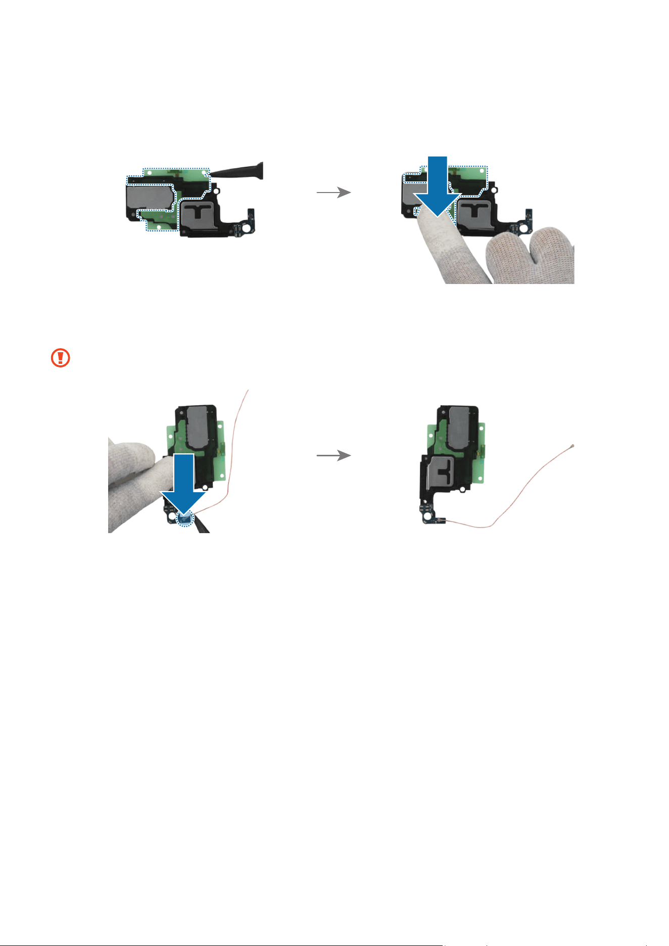
Disassembly and Assembly
167
2 Remove the clear film of a new speaker 2 adhesive tape and apply it to the bottom of
the new speaker 2. Gently press down the tape with your fingers so that the tape can
be attached well.
3 Using the tweezers, connect the coaxial cable connector (Orange) to the new speaker
module.
Be careful not to damage the speaker and cable.
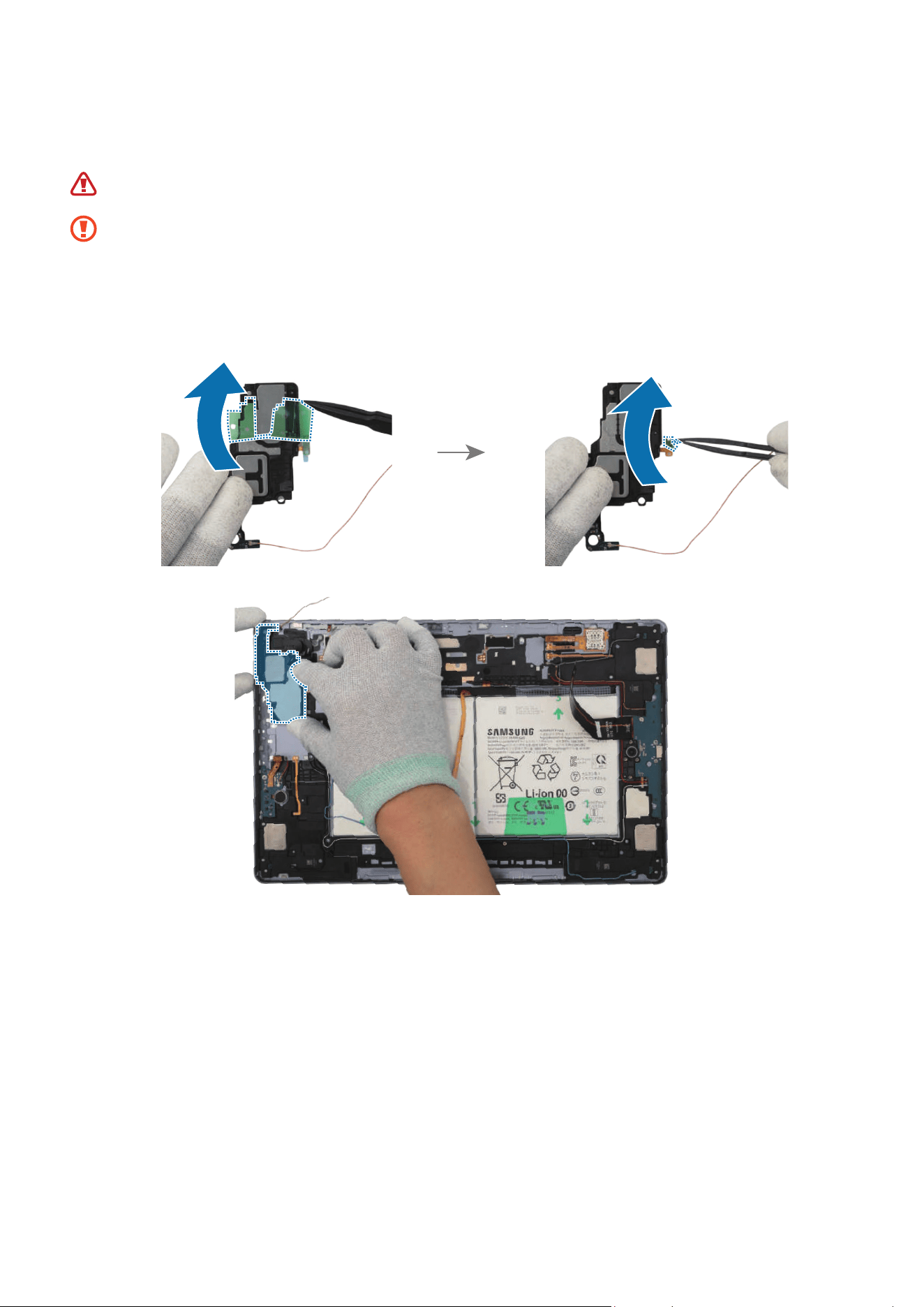
Disassembly and Assembly
168
4 Using the tweezers or your fingers, remove all release films of the new speaker. Place
the speaker module to the exact position, and assemble it to the back cover module.
Be careful not to damage the battery.
•
The cables have to positioned outside so as not to interfere when assembling
the speaker.
•
Be careful not to damage the speaker and cable.
•
Be careful not to damage the near components.
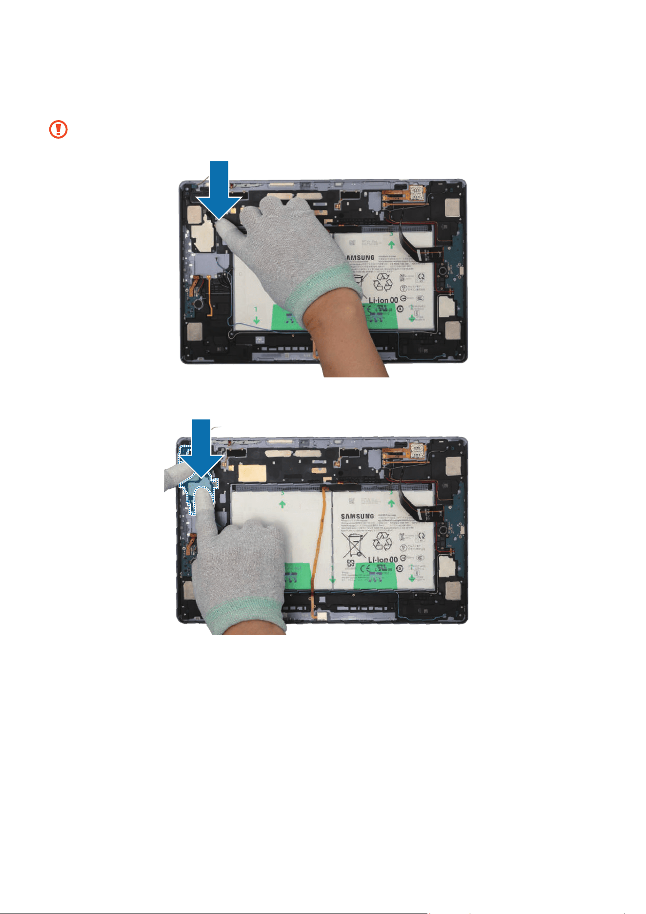
Disassembly and Assembly
169
5 Using your fingers, press down softly and evenly on the speaker module and the FPCB
so that the speaker module can be completely attached.
Be careful not to damage the speaker and FPCB.
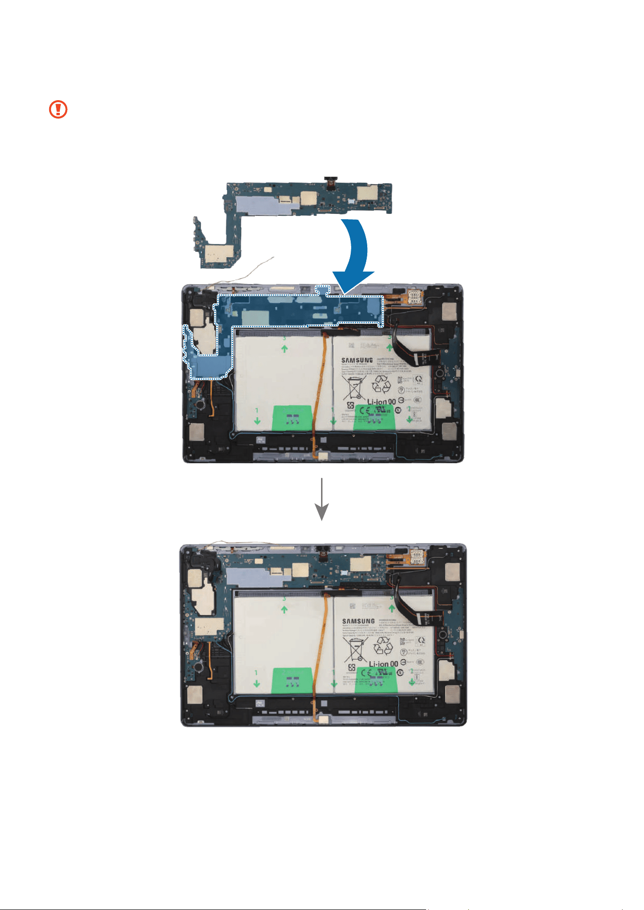
Disassembly and Assembly
170
6 Place the main board to the exact position, and assemble it to the back cover module.
•
The cables have to positioned outside so as not to interfere when assembling
the main board.
•
Be careful not to damage the main board and near components.
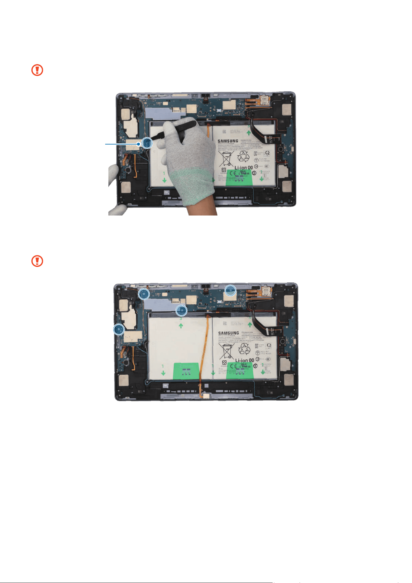
Disassembly and Assembly
171
7 Using the tweezers, connect the coaxial cable (Orange) to the main board.
Be careful not to damage the cables and near components.
Coaxial cable
(Orange)
8 Check the screw 3463 (4 ea) and fasten them on the main board using a cross-head
screwdriver.
Be careful not to damage the main board and near components.
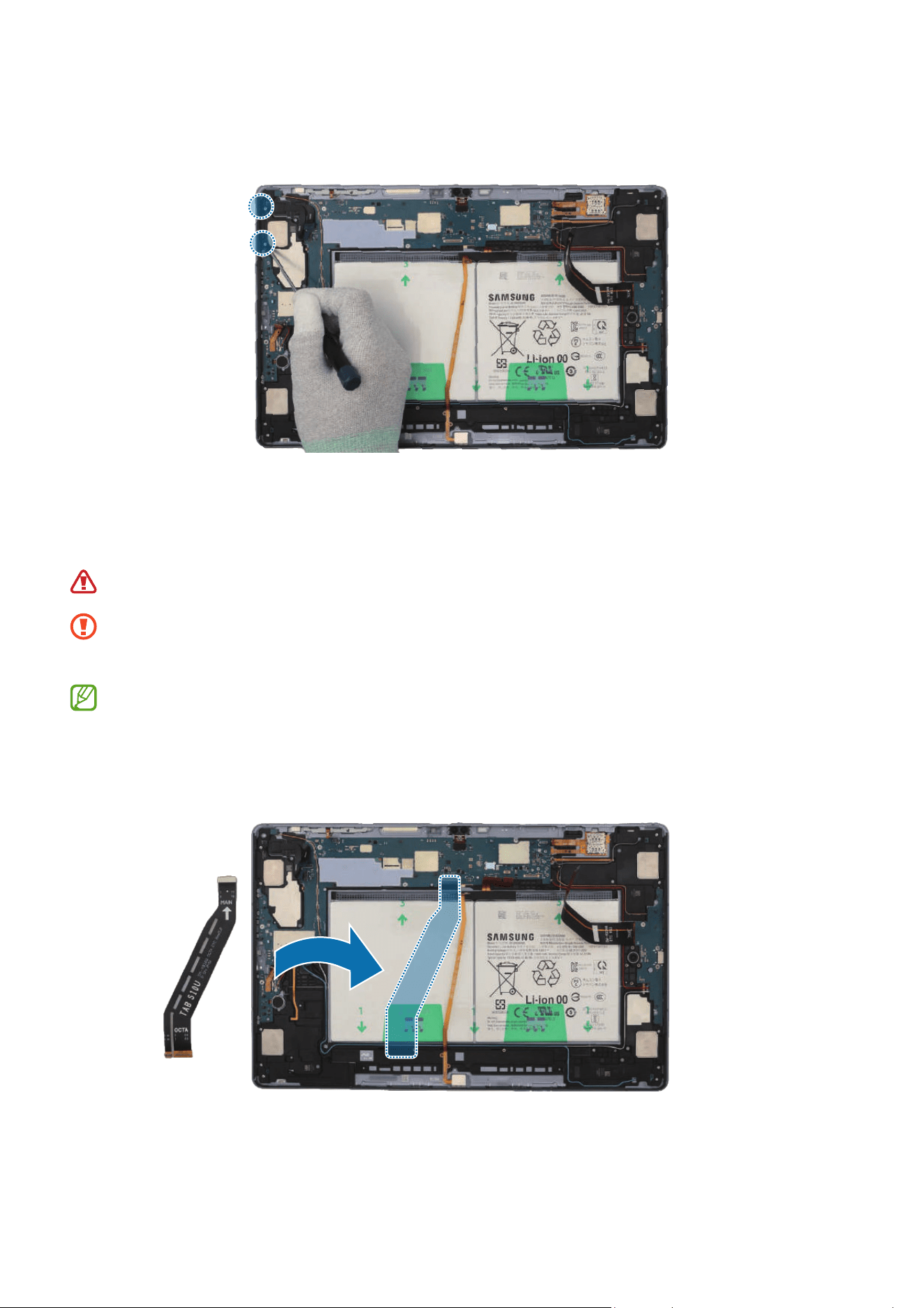
Disassembly and Assembly
172
9 Check the screw 3405 (2 ea) and fasten them on the speaker using a cross-head
screwdriver.
10
Using the tweezers, connect the 8 connectors and the 3 coaxial cable connectors
(Orange/Black/Red) to the main board. For the 5G or LTE devices, connect the
additional 5 coaxial cable connectors (Blue/White/Grey/Orange/Red).
Be careful not to damage the battery.
•
Be careful not to damage the cable while connecting the connector.
•
Be careful not to damage the near components.
•
The 5 coaxial cables (Blue/White/Grey/Orange/Red) are only available for the
5G or LTE devices.
•
The cables and connectors may vary depending on the country, region, or
specifications.

Disassembly and Assembly
173
Coaxial cable
(White)
Coaxial cable
(Blue)
Coaxial cable
(Grey)
Coaxial cable (Red)
Coaxial cable
(Orange)


Disassembly and Assembly
175
Speaker 3
Disassembly
Remove the Screen and Bracket first before you begin.
1 Using the tweezers, disconnect the battery connector from the main board first.
Separate the 8 connectors and the 3 coaxial cable connectors (Orange/Black/Red)
from the main board. For the 5G or LTE devices, separate the additional 5 coaxial
cable connectors (Blue/White/Grey/Orange/Red).
•
Make sure to first disconnect the battery connector for your own safety.
•
Be careful not to damage the battery.
•
Be careful not to damage the cable while removing the connector.
•
Be careful not to damage the near components.
•
The 5 coaxial cables (Blue/White/Grey/Orange/Red) are only available for the
5G or LTE devices.
•
The cables and connectors may vary depending on the country, region, or
specifications.

Disassembly and Assembly
176

Disassembly and Assembly
177
Coaxial cable
(White)
Coaxial cable
(Blue)
Coaxial cable
(Grey)
Coaxial cable (Red)
Coaxial cable
(Orange)
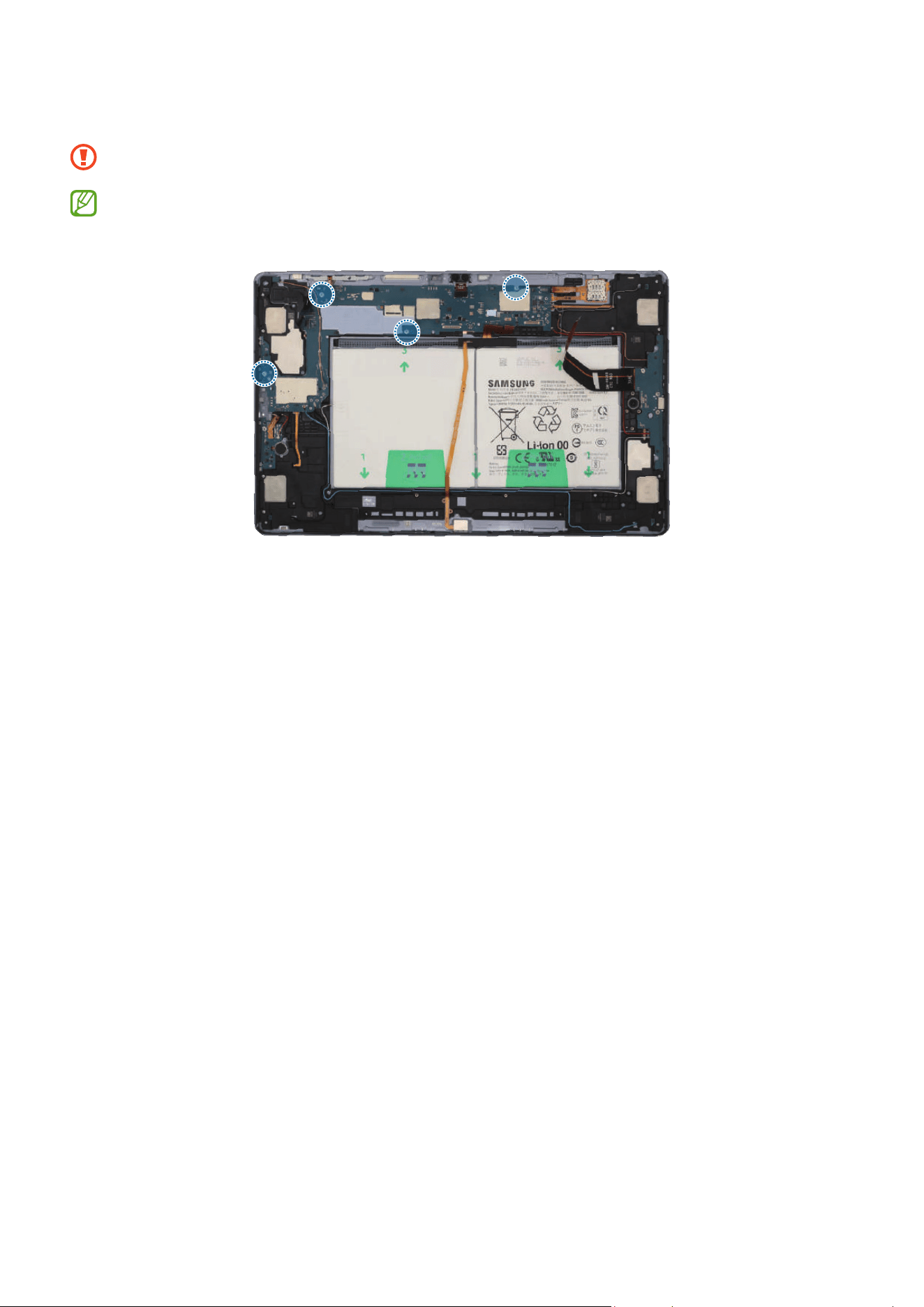
Disassembly and Assembly
178
2 Check and remove the 4 screws on the main board using a cross-head screwdriver.
Be careful not to damage the main board and near components.
Check the number of screws that have been removed, and store them carefully to
make sure that no unassembled screws are left inside the device during assembly.
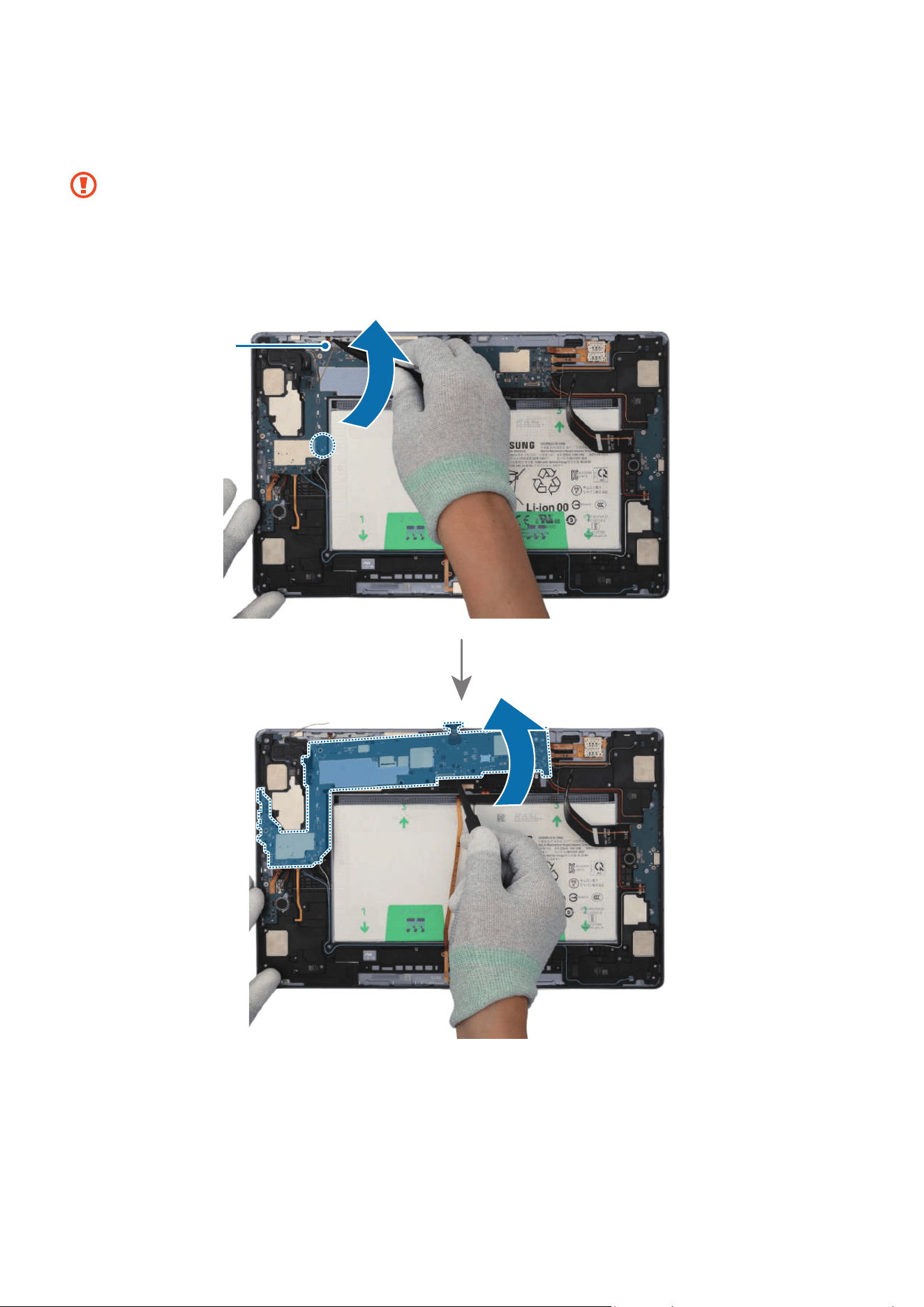
Disassembly and Assembly
179
3 Using the tweezers, disconnect the coaxial cable (Orange) from the main board. Then,
lift up on the separator groove of the main board and remove the main board module.
•
Be careful not to damage the battery connector, the main board, and near
components.
•
The cables have to positioned outside so as not to interfere when disassembling
the main board.
Coaxial cable
(Orange)
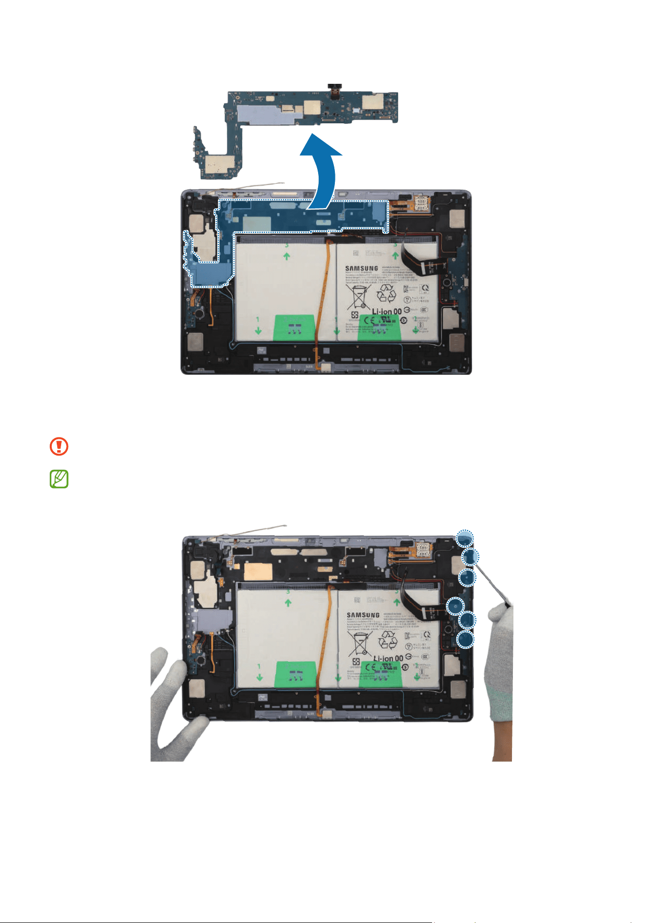
Disassembly and Assembly
180
4 Check the 3 screws on the speaker and the 3 screws on the charging port. Remove all
6 screws using a cross-head screwdriver.
Be careful not to damage the charging port and near components.
Check the number of screws that have been removed, and store them carefully to
make sure that no unassembled screws are left inside the device during assembly.

Disassembly and Assembly
181
5 For the 5G or LTE devices, disconnect the 4 coaxial cables (Blue/White/Orange/
Red) in the speaker modules with the tweezers. Using the tweezers, lift up on the
separator groove of the charging port module, and remove it carefully.
•
Check the position of the overlapping cables and disconnect them in order from
the top.
•
Be careful not to damage the cables and near components.
•
The 4 coaxial cables (Blue/White/Orange/Red) are only available for the 5G or
LTE devices.
•
The cables and connectors may vary depending on the country, region, or
specifications.
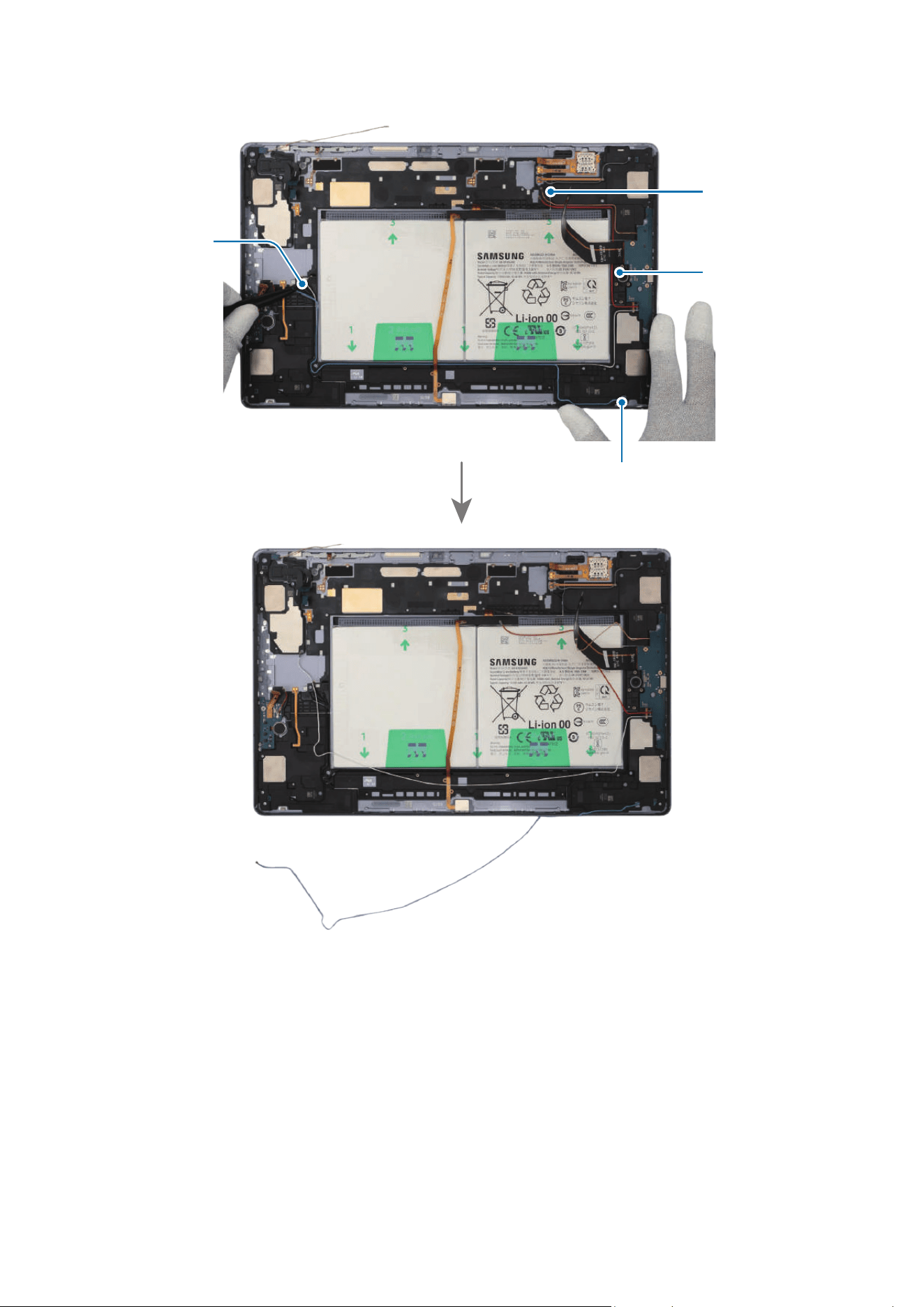
Disassembly and Assembly
182
Coaxial cable (Blue)
Coaxial cable
(Red)
Coaxial cable
(Orange)
Coaxial cable
(White)
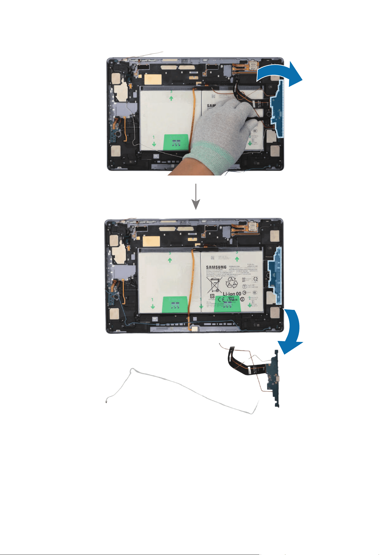
Disassembly and Assembly
183
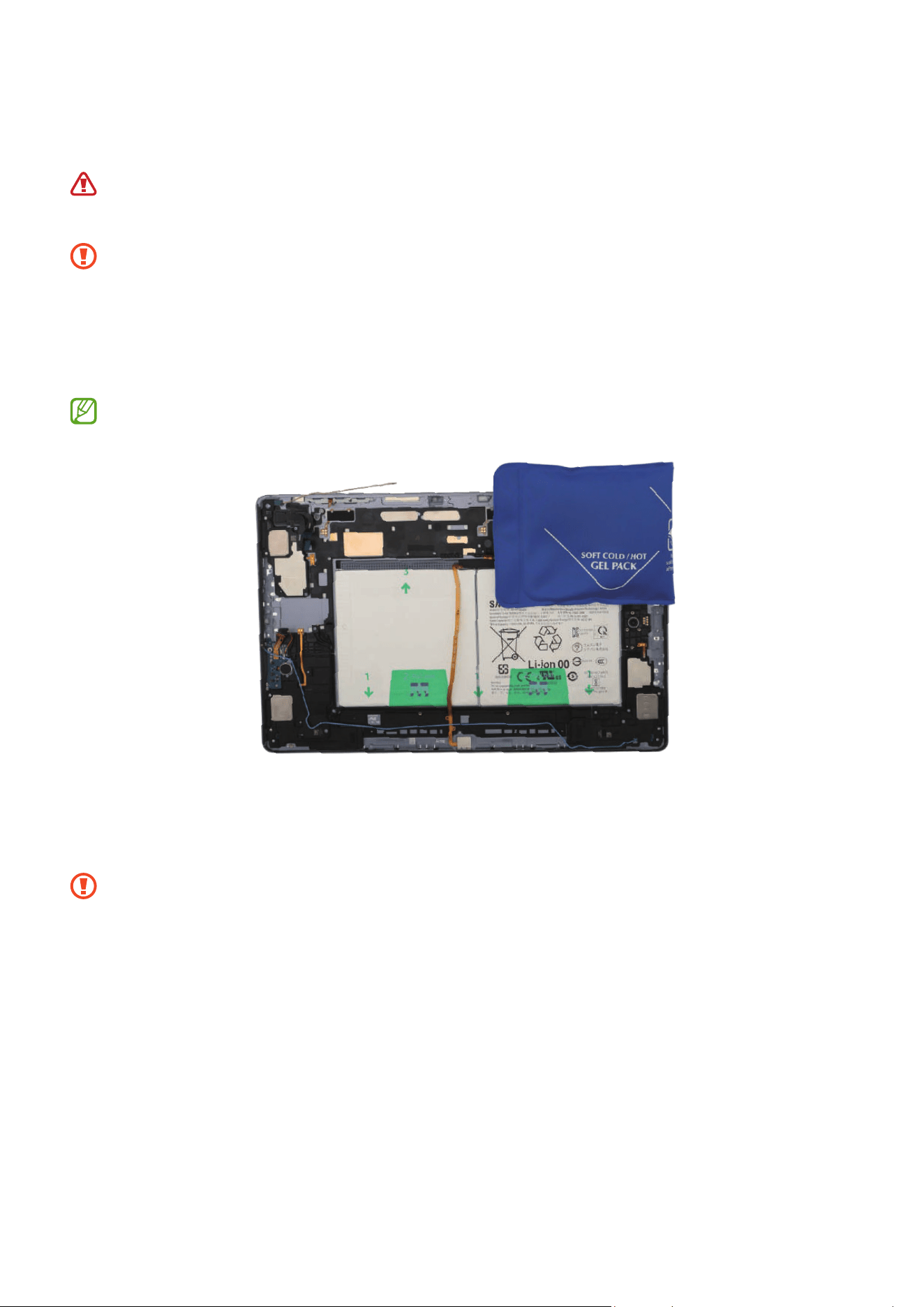
Disassembly and Assembly
184
6 Heat the microwaveable heating bag and apply it to the both front and back side of
the speaker module for 4 minutes.
•
It is possible for the device or battery to be damaged by heat.
•
Do not heat the device in a microwave. Doing so could cause an explosion.
•
Follow the heating bag’s instructions for heating. The recommended time for
heating the bag is 50 seconds in a 1000 W microwave and 70 seconds in a 700 W
microwave. (Correct temperature for use: 55-65 ℃.)
•
Be careful not to damage the device through excessive heat. (It is
recommended to disassemble the device in an area with a temperature gauge.)
When reheating, it should be heated no longer than 30 seconds.
7 Using the tweezers, separate the FPCB of speaker module carefully. Insert the
tweezers into the separator groove of the speaker and remove it from the back cover
module.
Be careful not to damage the cables and near components.
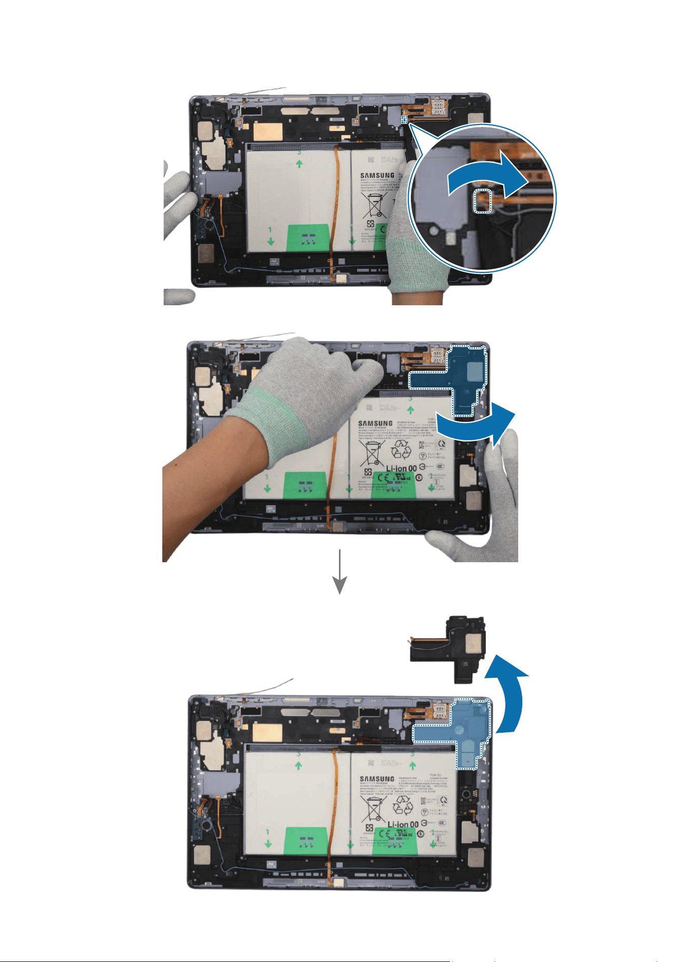
Disassembly and Assembly
185
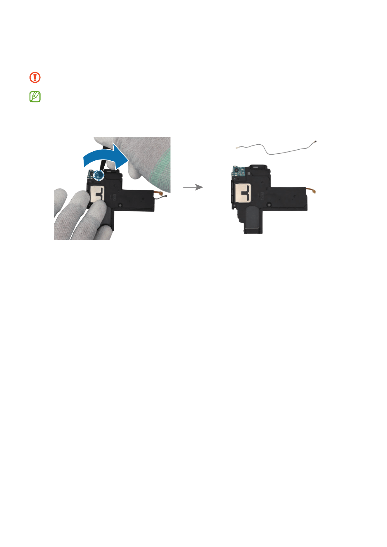
Disassembly and Assembly
186
8 For the 5G or LTE devices, separate the coaxial cable connector (Grey) from the
speaker module.
Be careful not to damage the cable.
•
The coaxial cable (Grey) is only available for the 5G or LTE devices.
•
The cables and connectors may vary depending on the country, region, or
specifications.
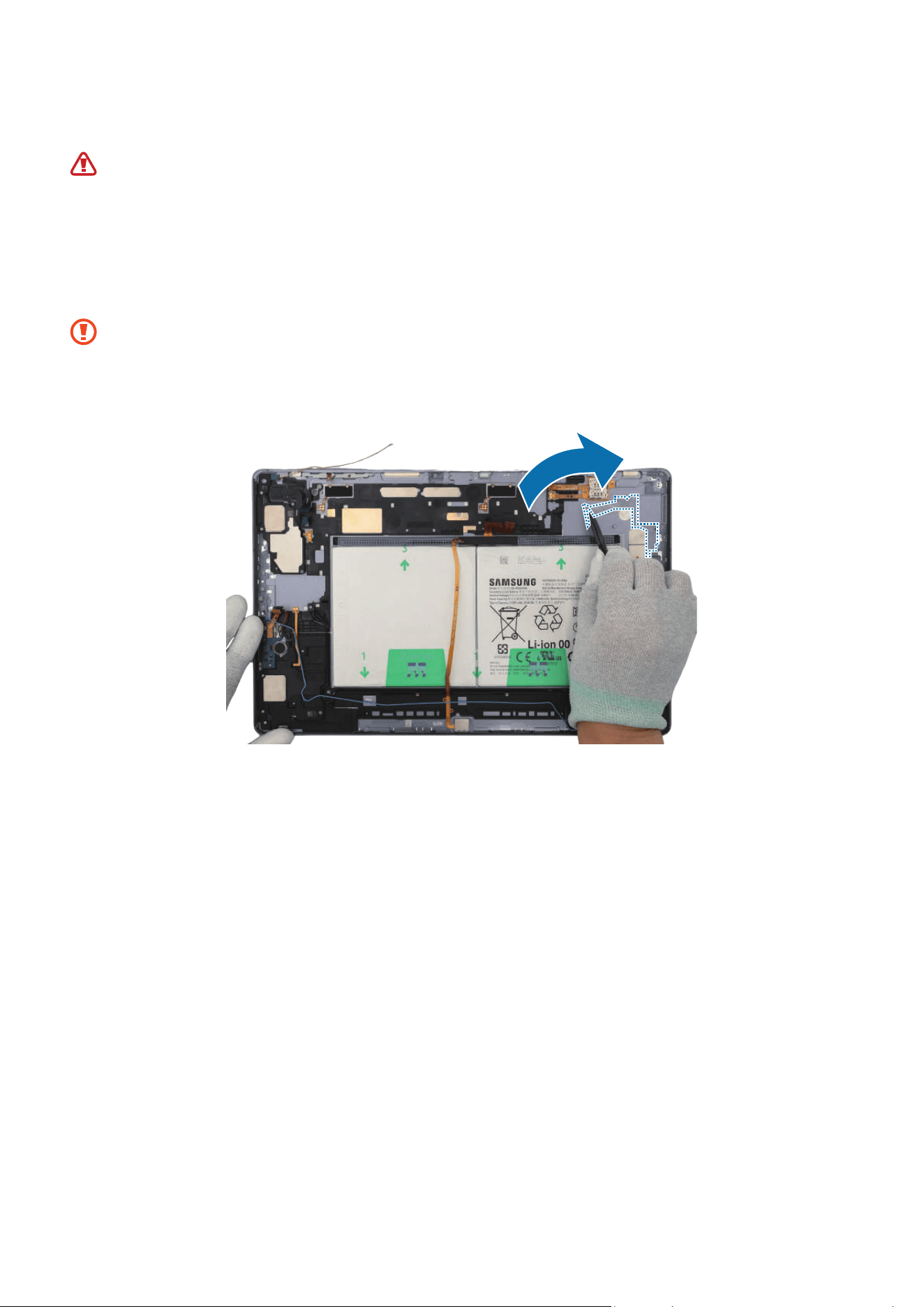
Disassembly and Assembly
187
Reassembly
Leaving screws inside the device may damage internal components, such as the
battery. During assembly, be extra careful not to leave any unassembled screws
inside the device.
1 Using the tweezers and your fingers, remove all adhesive tapes from where the
speaker was attached.
•
Make sure to remove any residual tapes attached to the position of the
separated speaker before reassembling the new speaker.
•
Be careful not to damage the near components.
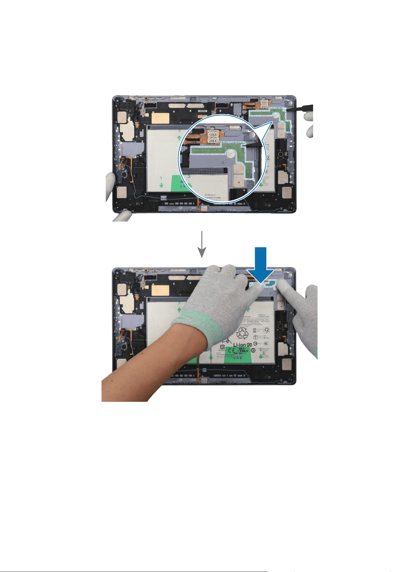
Disassembly and Assembly
188
2 Using the tweezers, remove the release film of a new speaker 3 adhesive tape (1 ea).
Align the outside shape of the tape with the speaker position and attach it accurately.
Gently press down the tape with your fingers so that the tape can be attached well.
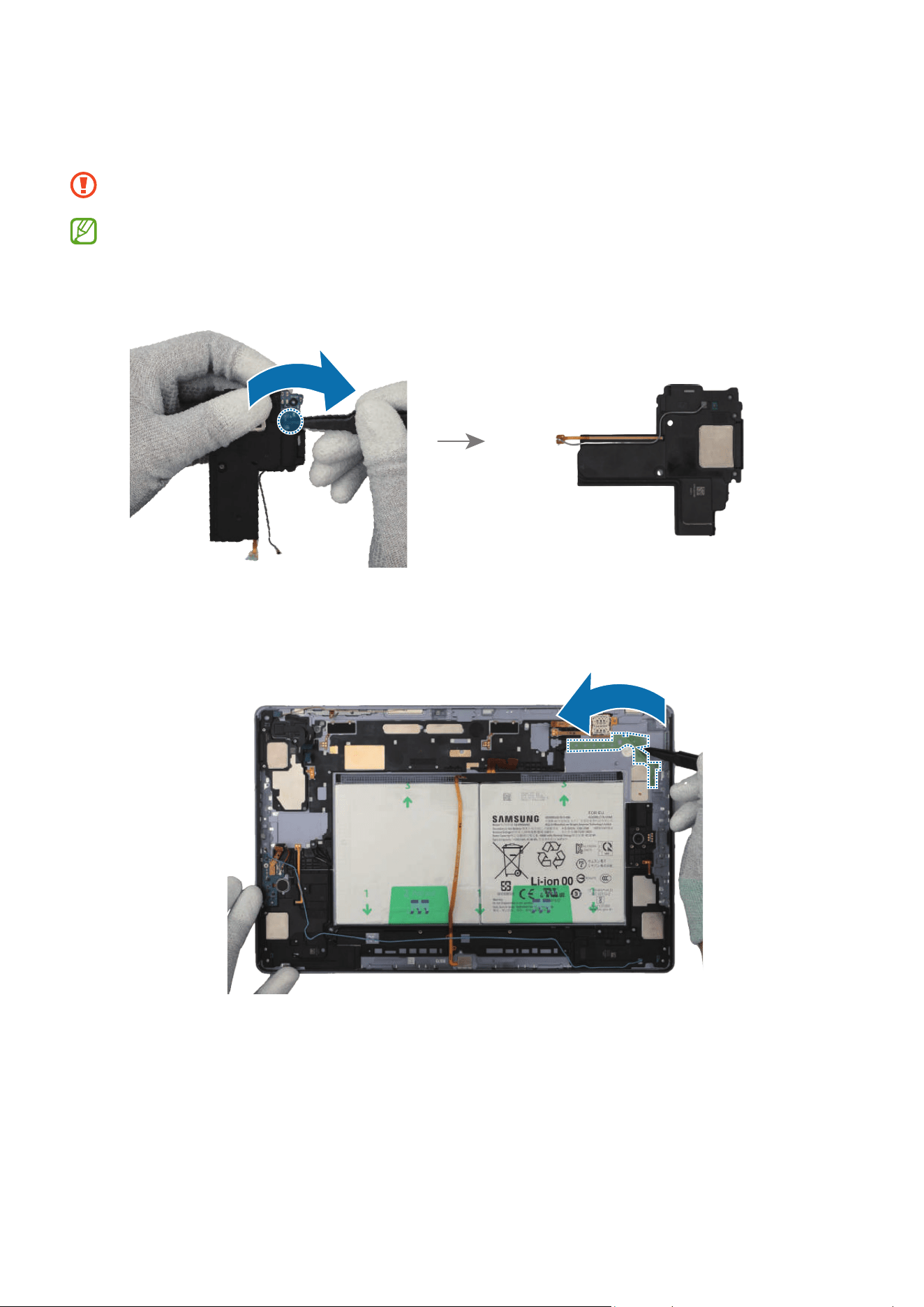
Disassembly and Assembly
189
3 For the 5G or LTE devices, connect the coaxial cable connector (Grey) to the new
speaker module.
Be careful not to damage the speaker and cable.
•
The coaxial cable (Grey) is only available for the 5G or LTE devices.
•
The cables and connectors may vary depending on the country, region, or
specifications.
4 Using the tweezers, hold the protruding release film of the attached tape and
carefully remove it.
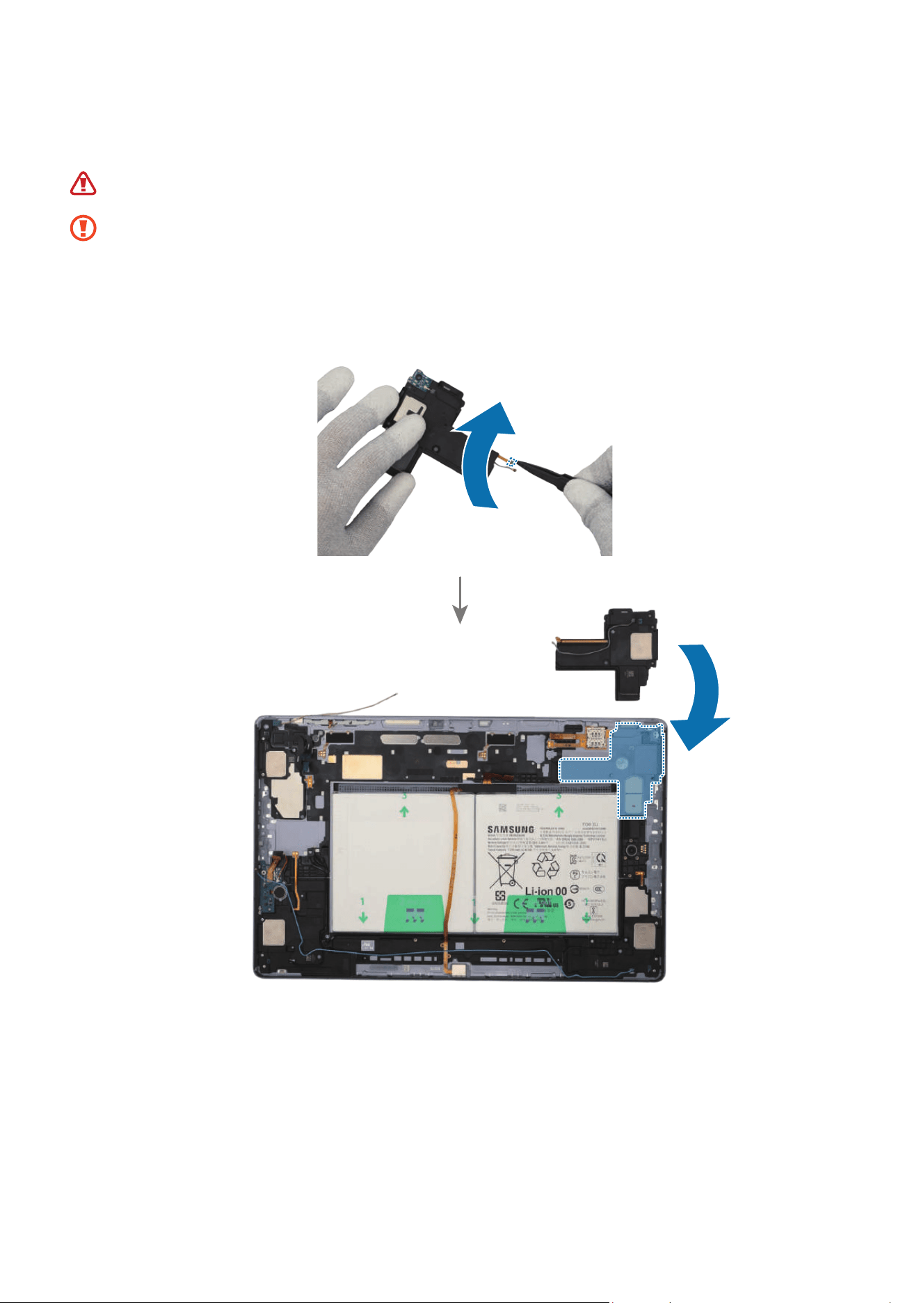
Disassembly and Assembly
190
5 Using the tweezers or your fingers, remove the release film of the new speaker. Place
the speaker module to the exact position, and assemble it to the back cover module.
Be careful not to damage the battery.
•
The cables have to positioned outside so as not to interfere when assembling
the speaker.
•
Be careful not to damage the speaker and cable.
•
Be careful not to damage the near components.
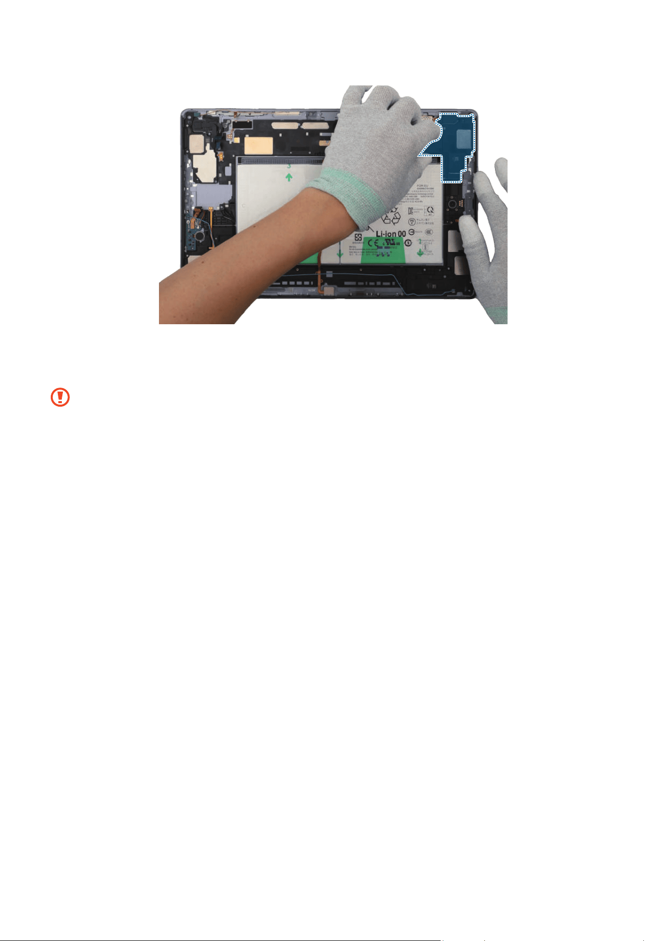
Disassembly and Assembly
191
6 Using your fingers, press down softly and evenly on the speaker module and the FPCB
so that the speaker module can be completely attached.
Be careful not to damage the speaker and FPCB.
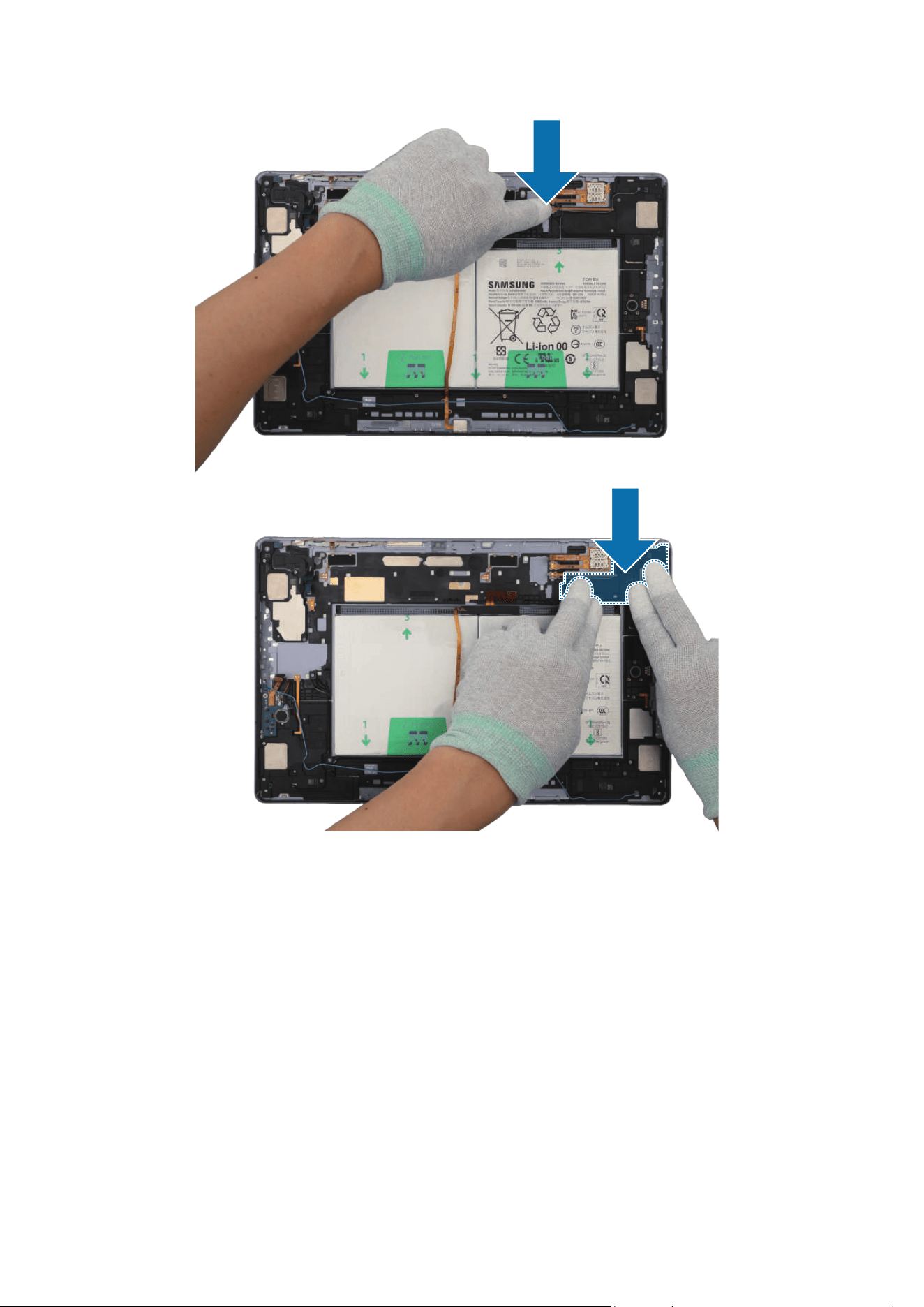
Disassembly and Assembly
192
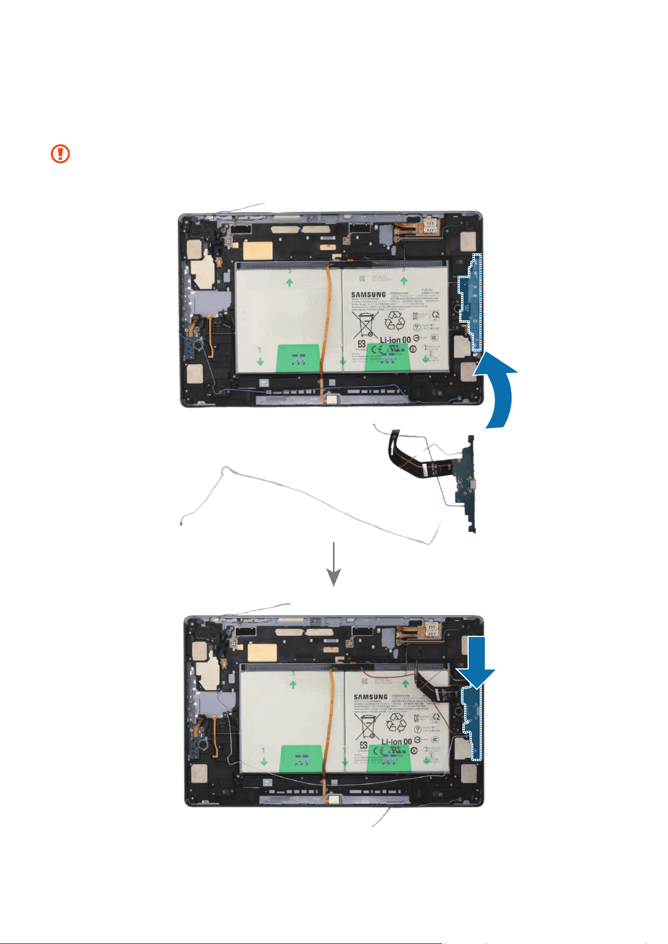
Disassembly and Assembly
193
7 Using the tweezers or your fingers, assemble the charging port to the back cover
module and press down softly and evenly on it so that the charging port can be
completely attached.
•
Be careful not to damage the charging port module side contact.
•
Be careful not to damage the near components.
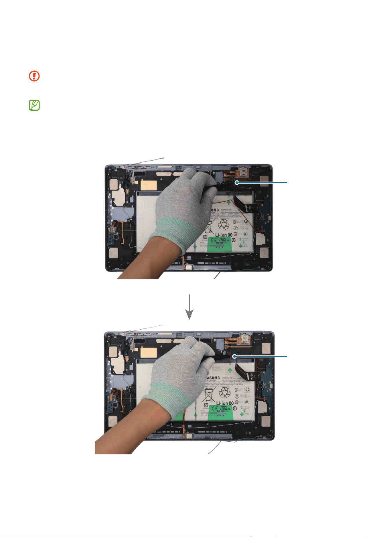
Disassembly and Assembly
194
8 For the 5G or LTE devices, connect the 4 coaxial cables (Orange/Red/White/Blue) to
the speaker modules.
•
Be careful not to damage the charging port and near components.
•
Be careful not to damage the cables.
•
The 4 coaxial cables (Orange/Red/White/Blue) are only available for the 5G or
LTE devices.
•
The cables and connectors may vary depending on the country, region, or
specifications.
Coaxial cable
(Orange)
Coaxial cable
(Red)
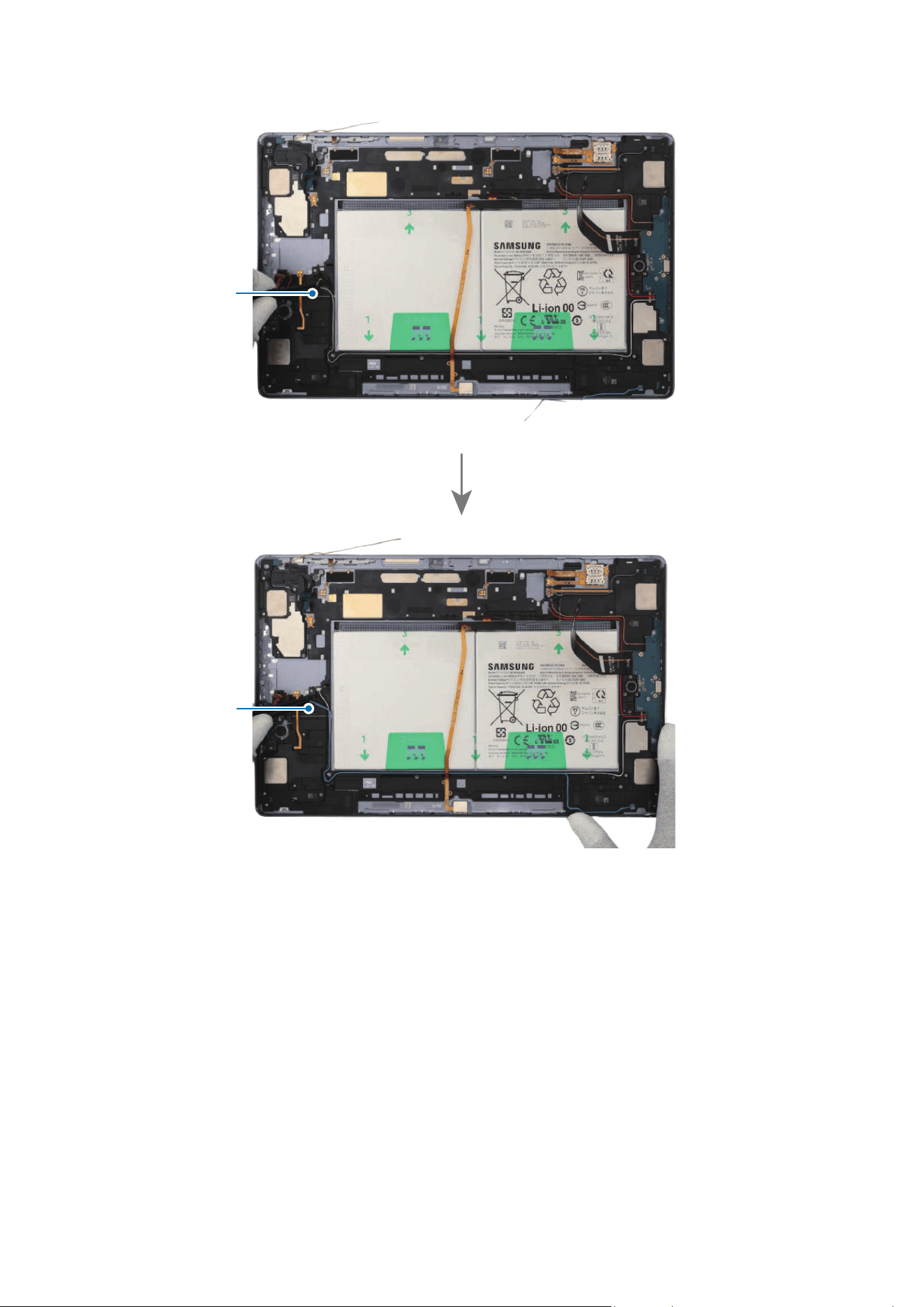
Disassembly and Assembly
195
Coaxial cable
(White)
Coaxial cable
(Blue)
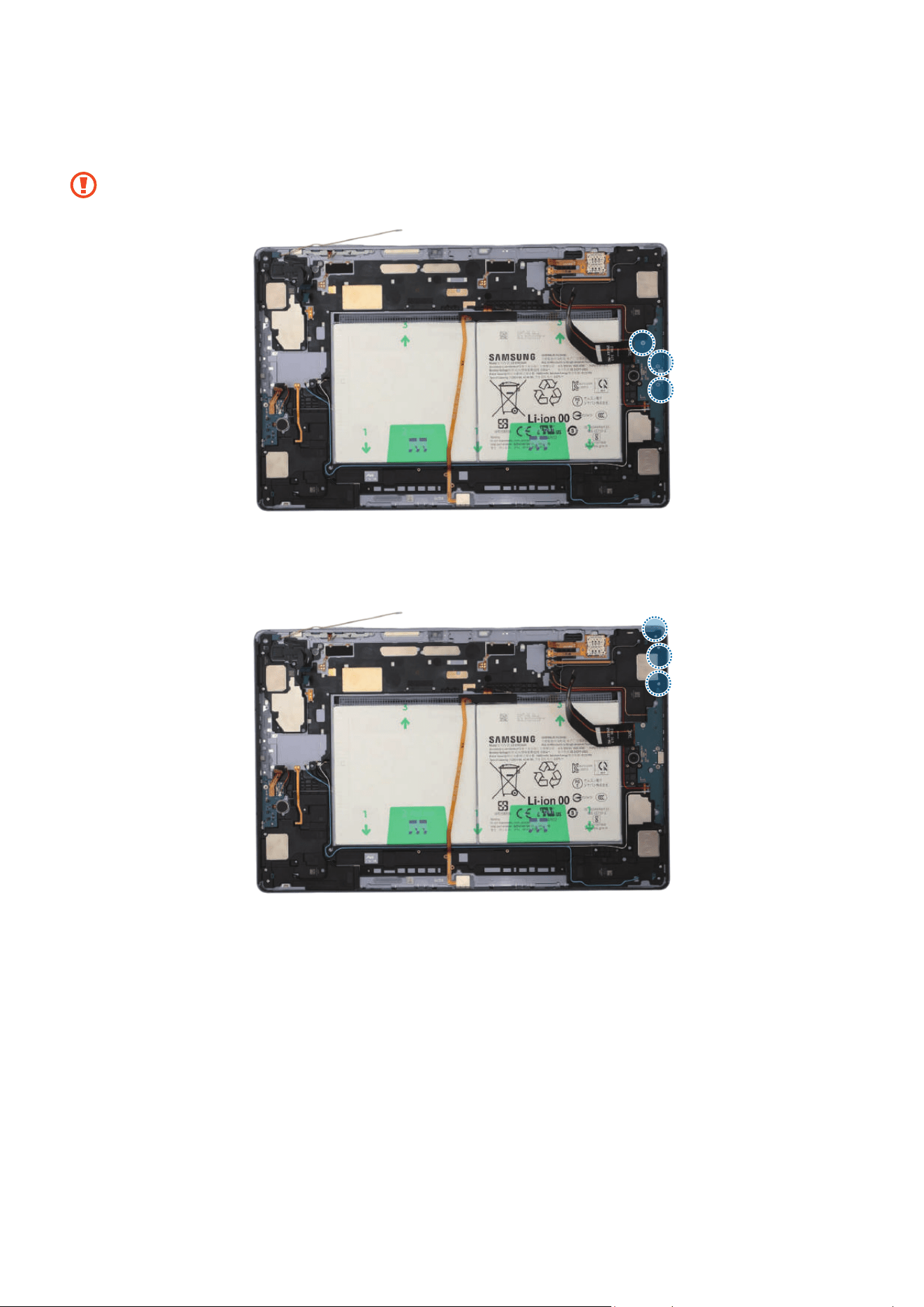
Disassembly and Assembly
196
9 Check the screw 3443 (3 ea) and fasten them on the charging port using a cross-head
screwdriver.
Be careful not to damage the charging port and near components.
10
Check the screw 3405 (3 ea) and fasten them on the speaker using a cross-head
screwdriver.
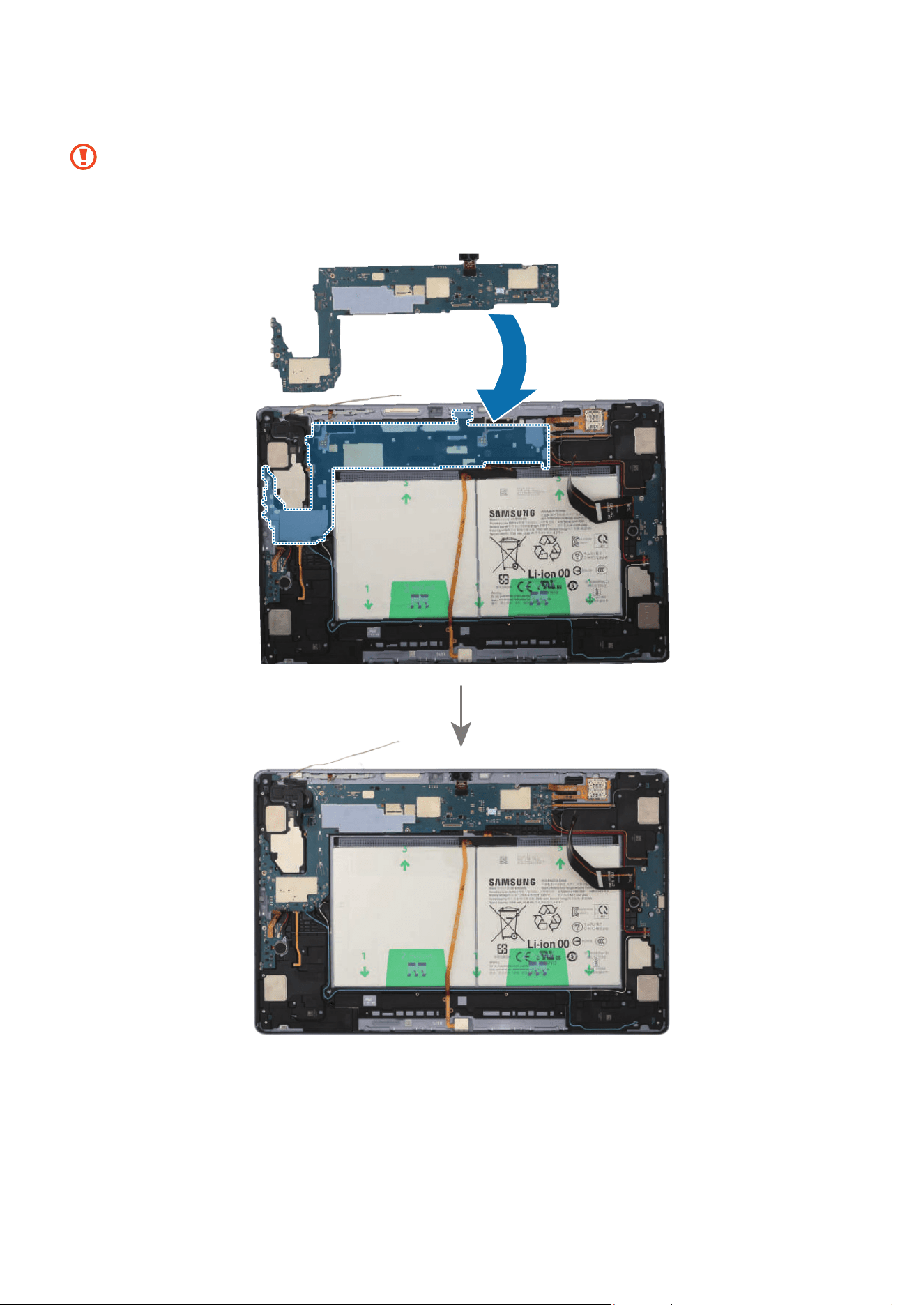
Disassembly and Assembly
197
11
Place the main board to the exact position, and assemble it to the back cover module.
•
The cables have to positioned outside so as not to interfere when assembling
the main board.
•
Be careful not to damage the main board and near components.

Disassembly and Assembly
198
12
Using the tweezers, connect the coaxial cable (Orange) to the main board.
Be careful not to damage the cables and near components.
Coaxial cable
(Orange)
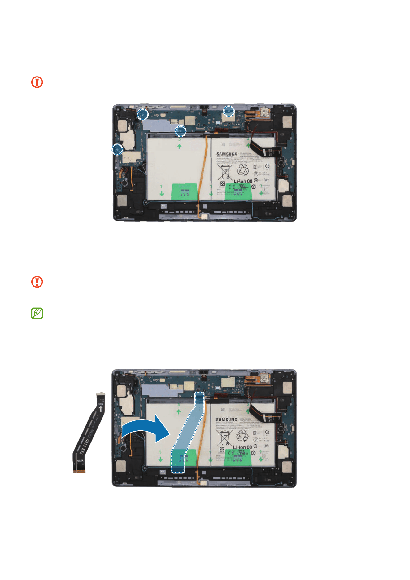
Disassembly and Assembly
199
13
Check the screw 3463 (4 ea) and fasten them on the main board using a cross-head
screwdriver.
Be careful not to damage the main board and near components.
14
Using the tweezers, connect the 8 connectors and the 3 coaxial cable connectors
(Orange/Red/Black) to the main board. For the 5G or LTE devices, connect the
additional 5 coaxial cable connectors (Blue/White/Grey/Orange/Red).
•
Be careful not to damage the cable while connecting the connector.
•
Be careful not to damage the near components.
•
The 5 coaxial cables (Blue/White/Grey/Orange/Red) are only available for the
5G or LTE devices.
•
The cables and connectors may vary depending on the country, region, or
specifications.
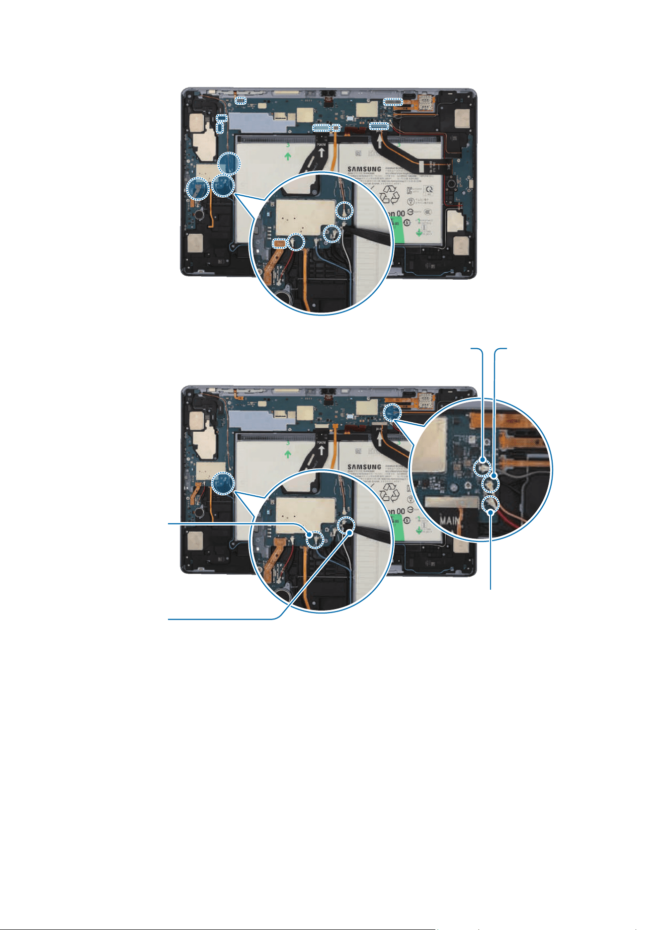
Disassembly and Assembly
200
Coaxial cable
(White)
Coaxial cable
(Blue)
Coaxial cable
(Grey)
Coaxial cable (Red)
Coaxial cable
(Orange)


Disassembly and Assembly
202
Speaker 4
Disassembly
Remove the Screen and Bracket first before you begin.
1 Using the tweezers, disconnect the battery connector from the main board first.
Separate the 3 connectors and the coaxial cable connector (Black) from the main
board. For the 5G or LTE devices, separate the additional 4 coaxial cable connectors
(Blue/White/Orange/Red).
•
Make sure to first disconnect the battery connector for your own safety.
•
Be careful not to damage the battery.
•
Be careful not to damage the cable while removing the connector.
•
Be careful not to damage the near components.
•
The 4 coaxial cables (Blue/White/Orange/Red) are only available for the 5G or
LTE devices.
•
The cables and connectors may vary depending on the country, region, or
specifications.
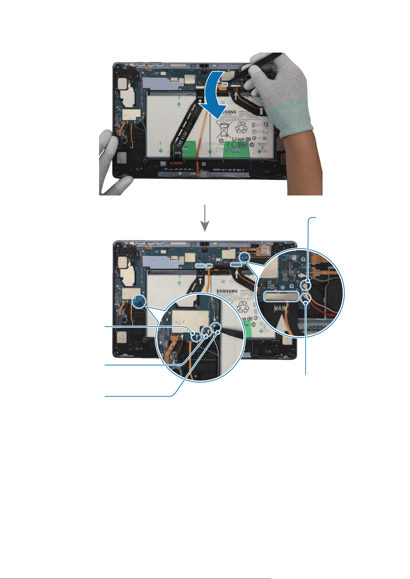
Disassembly and Assembly
203
Coaxial cable (Red)
Coaxial cable
(White)
Coaxial cable
(Blue)
Coaxial cable
(Black)
Coaxial cable
(Orange)
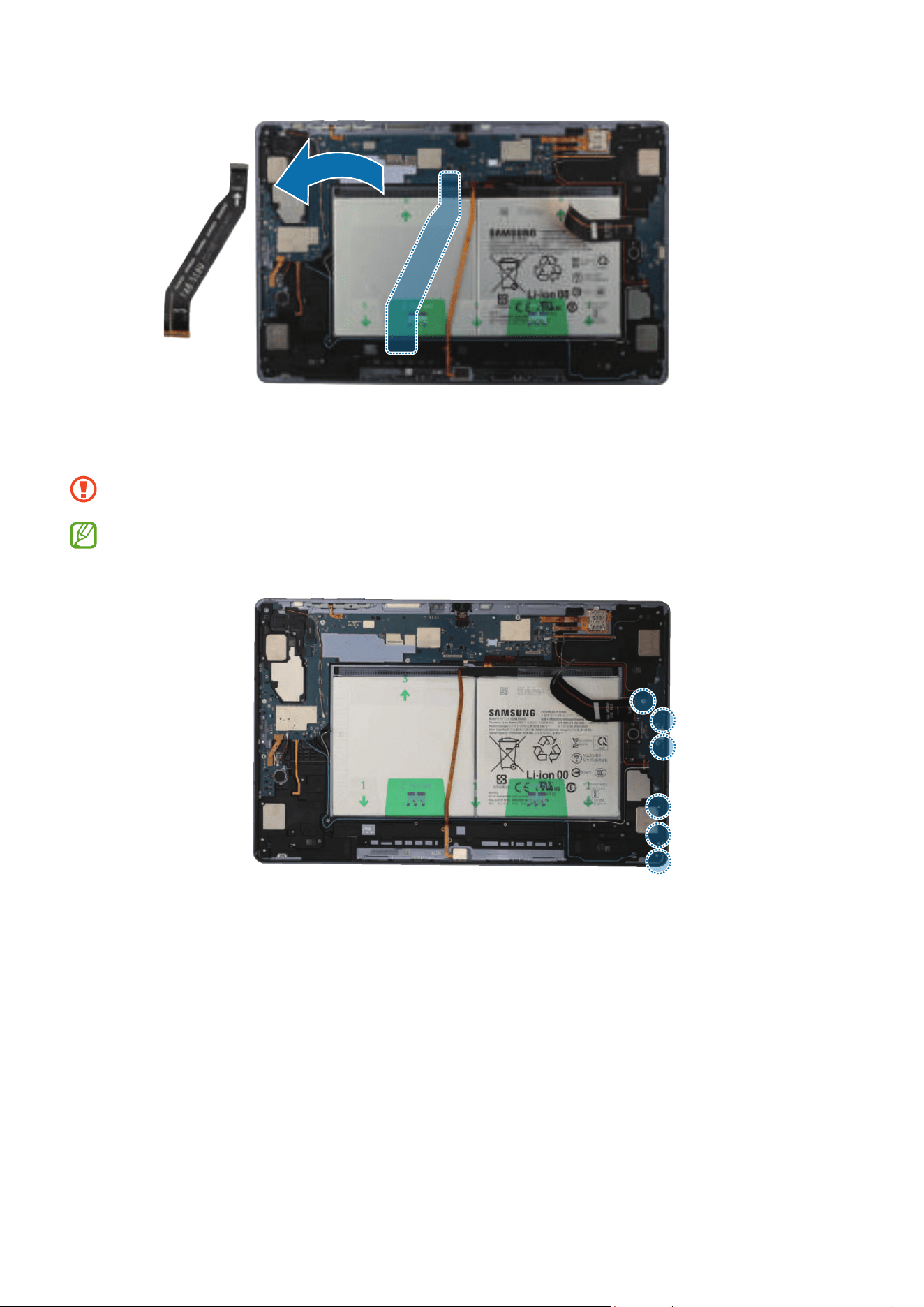
Disassembly and Assembly
204
2 Check the 3 screws on the speaker and the 3 screws on the charging port. Remove all
6 screws using a cross-head screwdriver.
Be careful not to damage the charging port and near components.
Check the number of screws that have been removed, and store them carefully to
make sure that no unassembled screws are left inside the device during assembly.
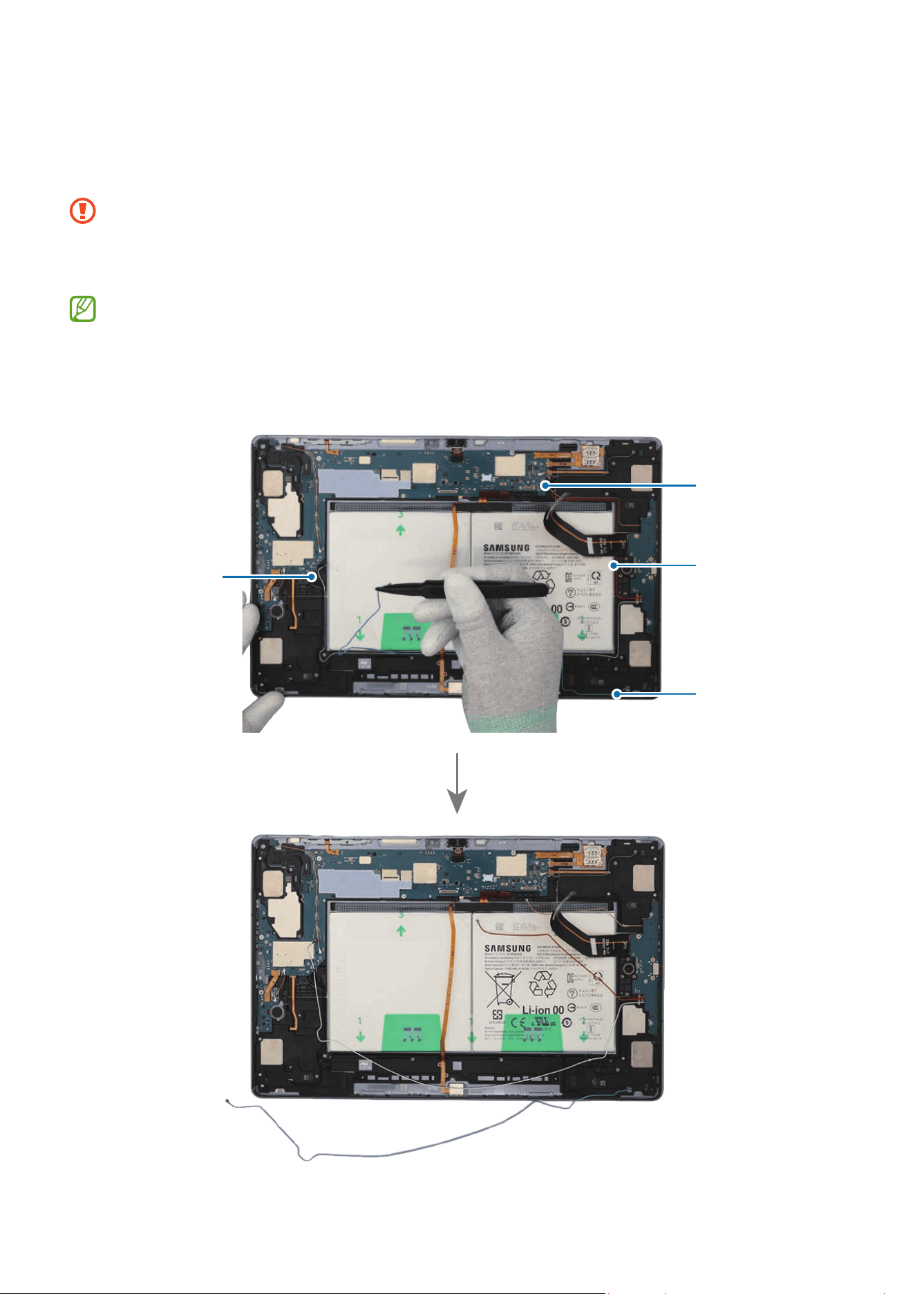
Disassembly and Assembly
205
3 For the 5G or LTE devices, disconnect the 4 coaxial cables (Blue/White/Orange/
Red) in the speaker modules with the tweezers. Using the tweezers, lift up on the
separator groove of the charging port module, and remove it carefully.
•
Check the position of the overlapping cables and disconnect them in order from
the top.
•
Be careful not to damage the cables and near components.
•
The 4 coaxial cables (Blue/White/Orange/Red) are only available for the 5G or
LTE devices.
•
The cables and connectors may vary depending on the country, region, or
specifications.
Coaxial cable
(Blue)
Coaxial cable
(Red)
Coaxial cable
(Orange)
Coaxial cable
(White)
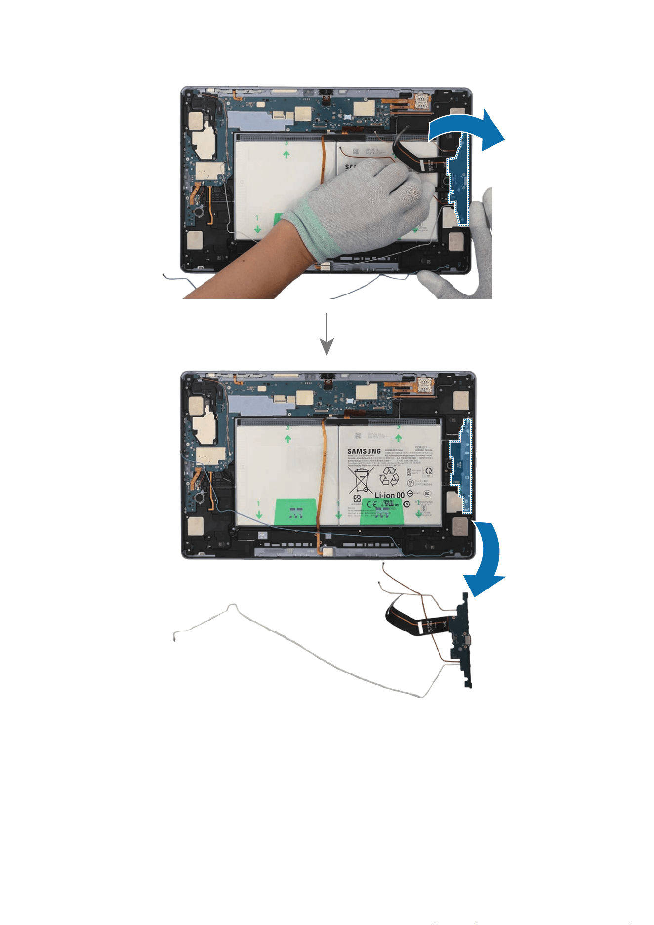
Disassembly and Assembly
206
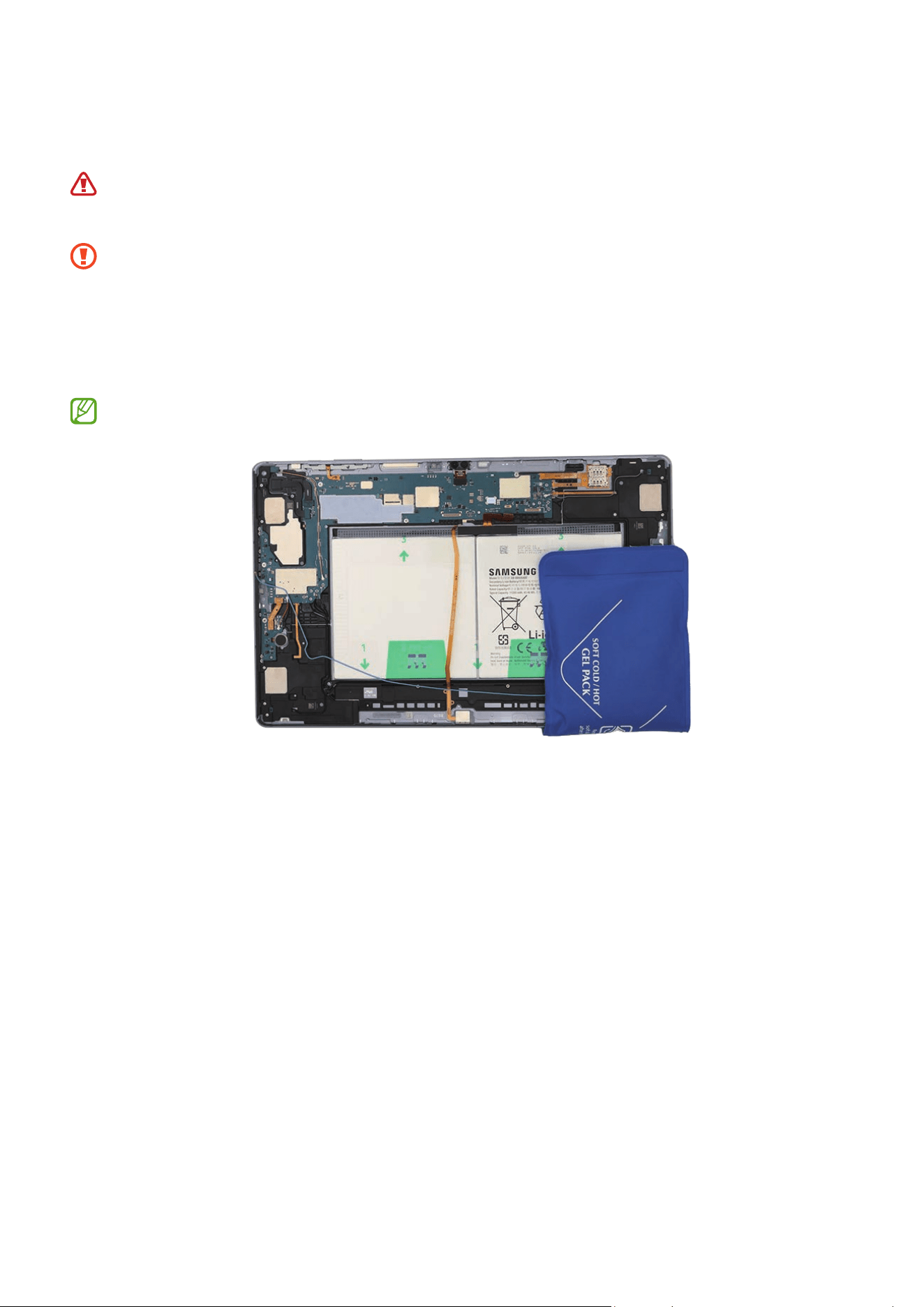
Disassembly and Assembly
207
4 Heat the microwaveable heating bag and apply it to the both front and back side of
the speaker module for 4 minutes.
•
It is possible for the device or battery to be damaged by heat.
•
Do not heat the device in a microwave. Doing so could cause an explosion.
•
Follow the heating bag’s instructions for heating. The recommended time for
heating the bag is 50 seconds in a 1000 W microwave and 70 seconds in a 700 W
microwave. (Correct temperature for use: 55-65 ℃.)
•
Be careful not to damage the device through excessive heat. (It is
recommended to disassemble the device in an area with a temperature gauge.)
When reheating, it should be heated no longer than 30 seconds.

Disassembly and Assembly
208
5 Using the tweezers, separate the FPCB of the speaker module carefully. Insert the
tweezers into the separator groove of the speaker and remove it from the back cover
module.
Be careful not to damage the cables and near components.
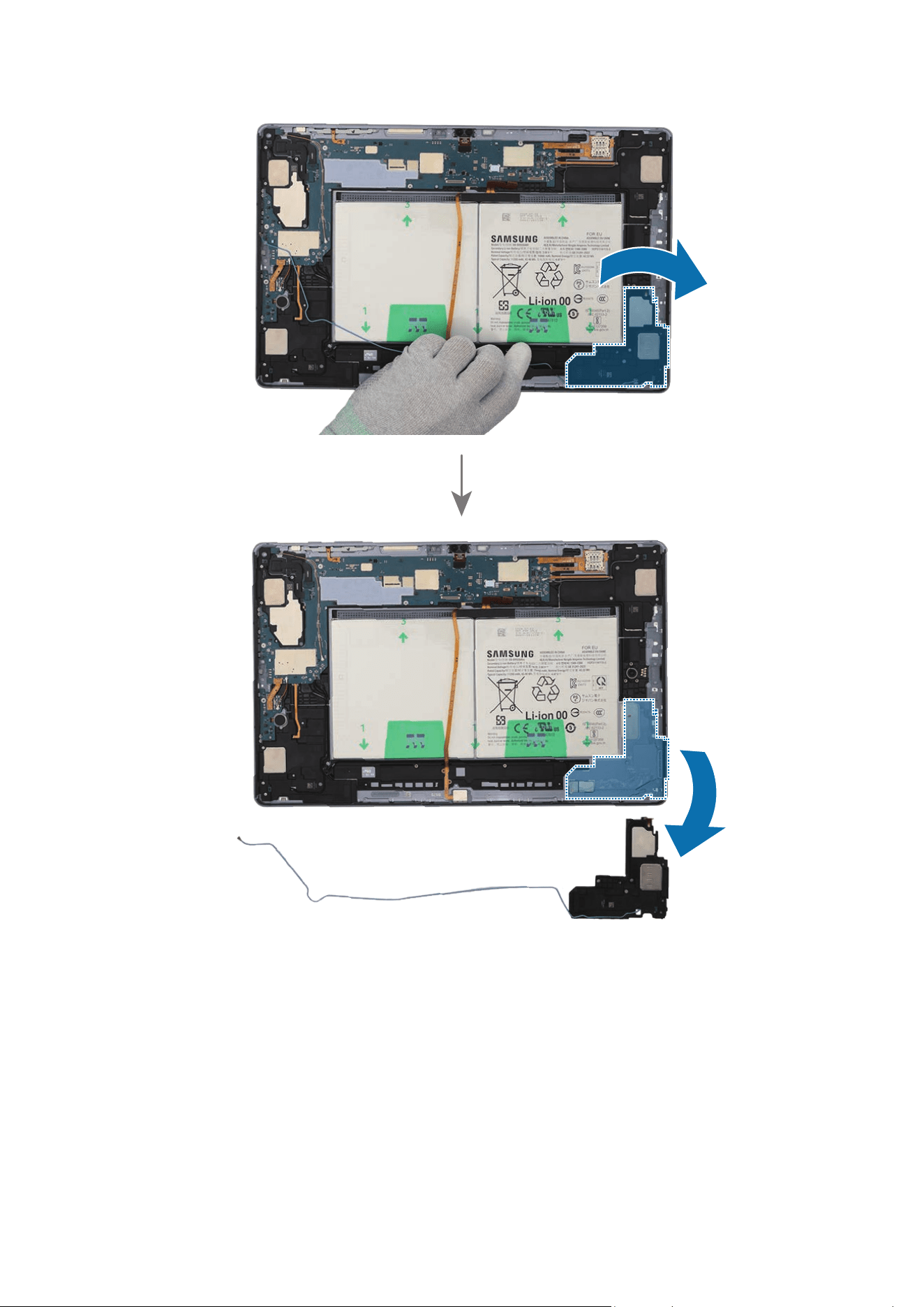
Disassembly and Assembly
209
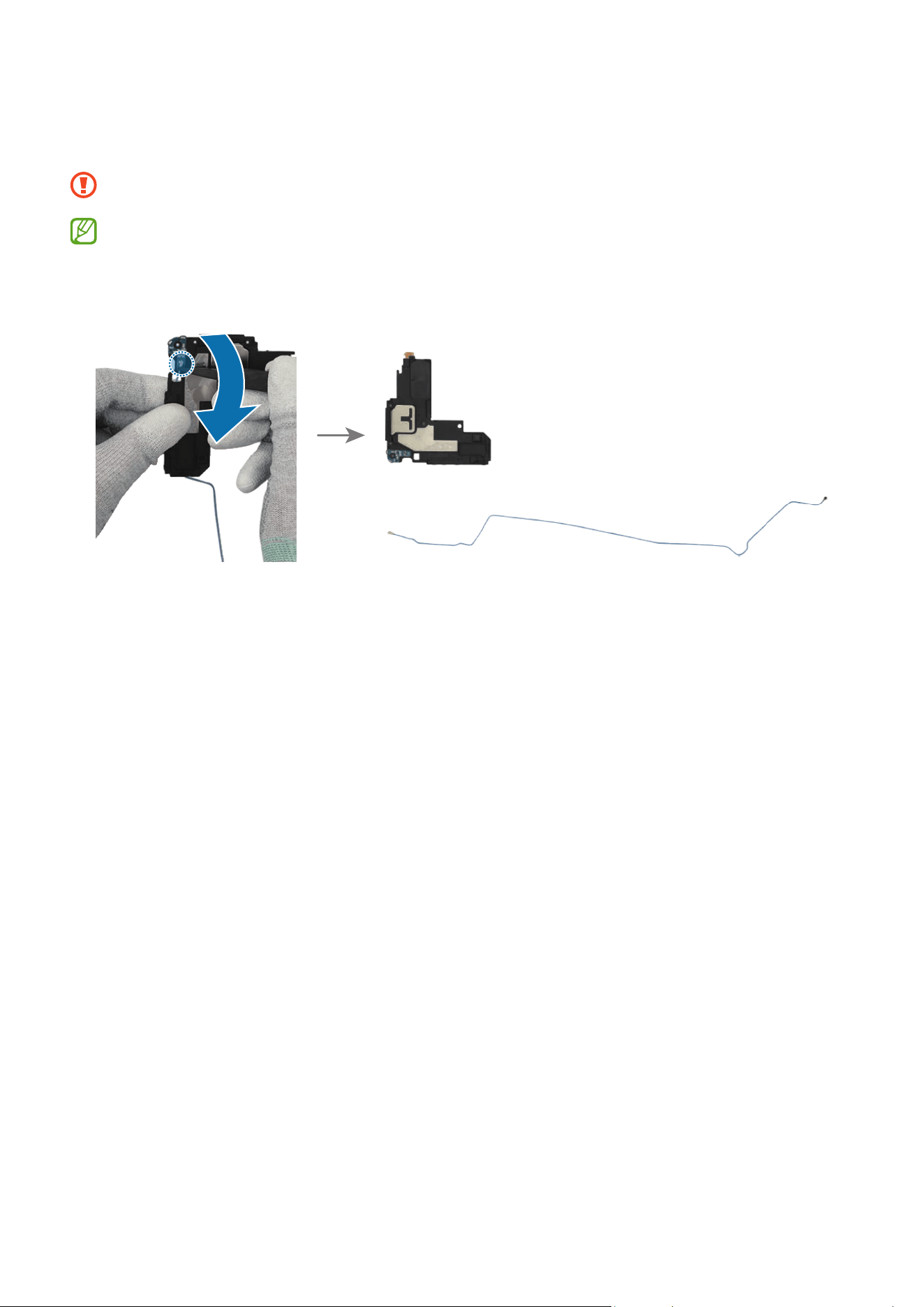
Disassembly and Assembly
210
6 For the 5G or LTE devices, separate the coaxial cable connector (Blue) from the
speaker module.
Be careful not to damage the cable.
•
The coaxial cable (Blue) is only available for the 5G or LTE devices.
•
The cables and connectors may vary depending on the country, region, or
specifications.
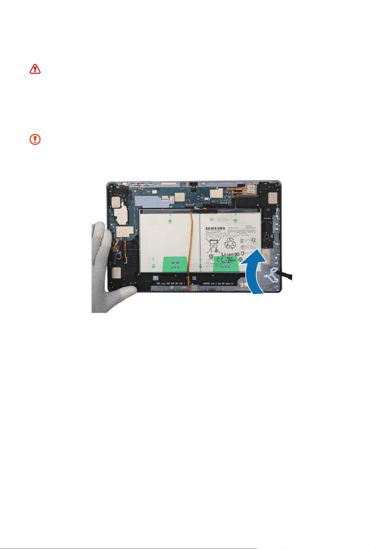
Disassembly and Assembly
211
Reassembly
Leaving screws inside the device may damage internal components, such as the
battery. During assembly, be extra careful not to leave any unassembled screws
inside the device.
1 Using the tweezers and your fingers, remove all adhesive tapes from where the
speaker was attached.
•
Make sure to remove any residual tapes attached to the position of the
separated speaker before reassembling the new speaker.
•
Be careful not to damage the near components.
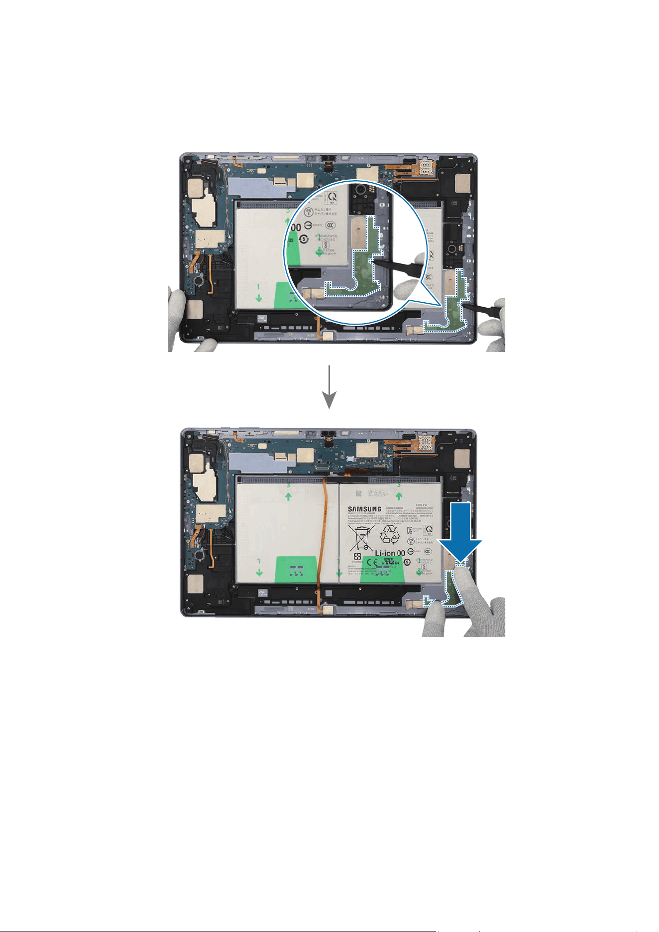
Disassembly and Assembly
212
2 Using the tweezers, remove the release film of a new speaker 4 adhesive tape (1 ea).
Align the outside shape of the tape with the speaker position and attach it accurately.
Gently press down the tape with your fingers so that the tape can be attached well.

Disassembly and Assembly
213
3 For the 5G or LTE devices, connect the coaxial cable connector (Blue) to the new
speaker module.
Be careful not to damage the speaker and cable.
•
The coaxial cable (Blue) is only available for the 5G or LTE devices.
•
The cables and connectors may vary depending on the country, region, or
specifications.
4 Using the tweezers, hold the protruding release film of the attached tape and
carefully remove it.
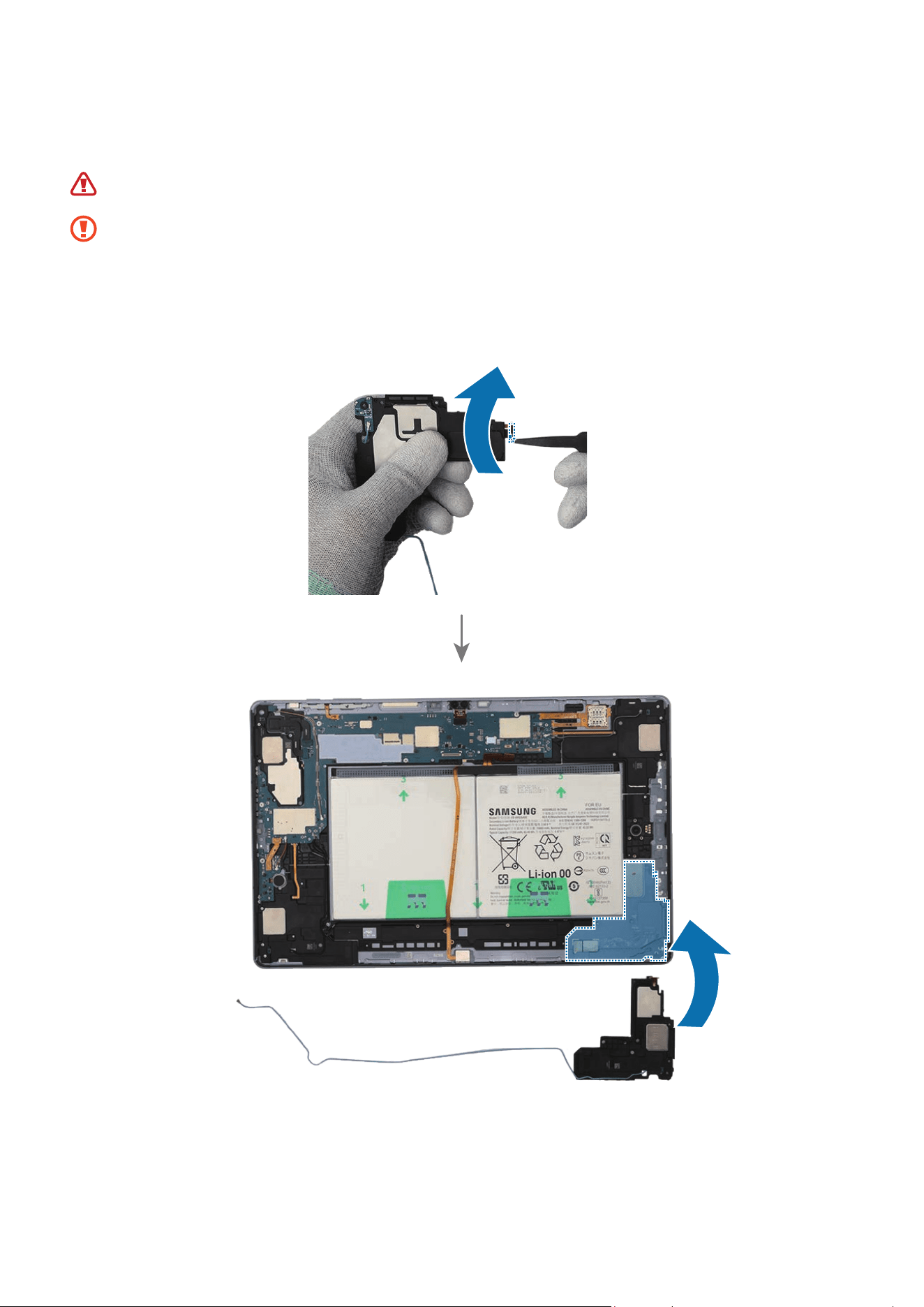
Disassembly and Assembly
214
5 Using the tweezers or your fingers, remove the release film of the new speaker. Place
the speaker module to the exact position, and assemble it to the back cover module.
Be careful not to damage the battery.
•
The cables have to positioned outside so as not to interfere when assembling
the speaker.
•
Be careful not to damage the speaker and cable.
•
Be careful not to damage the near components.
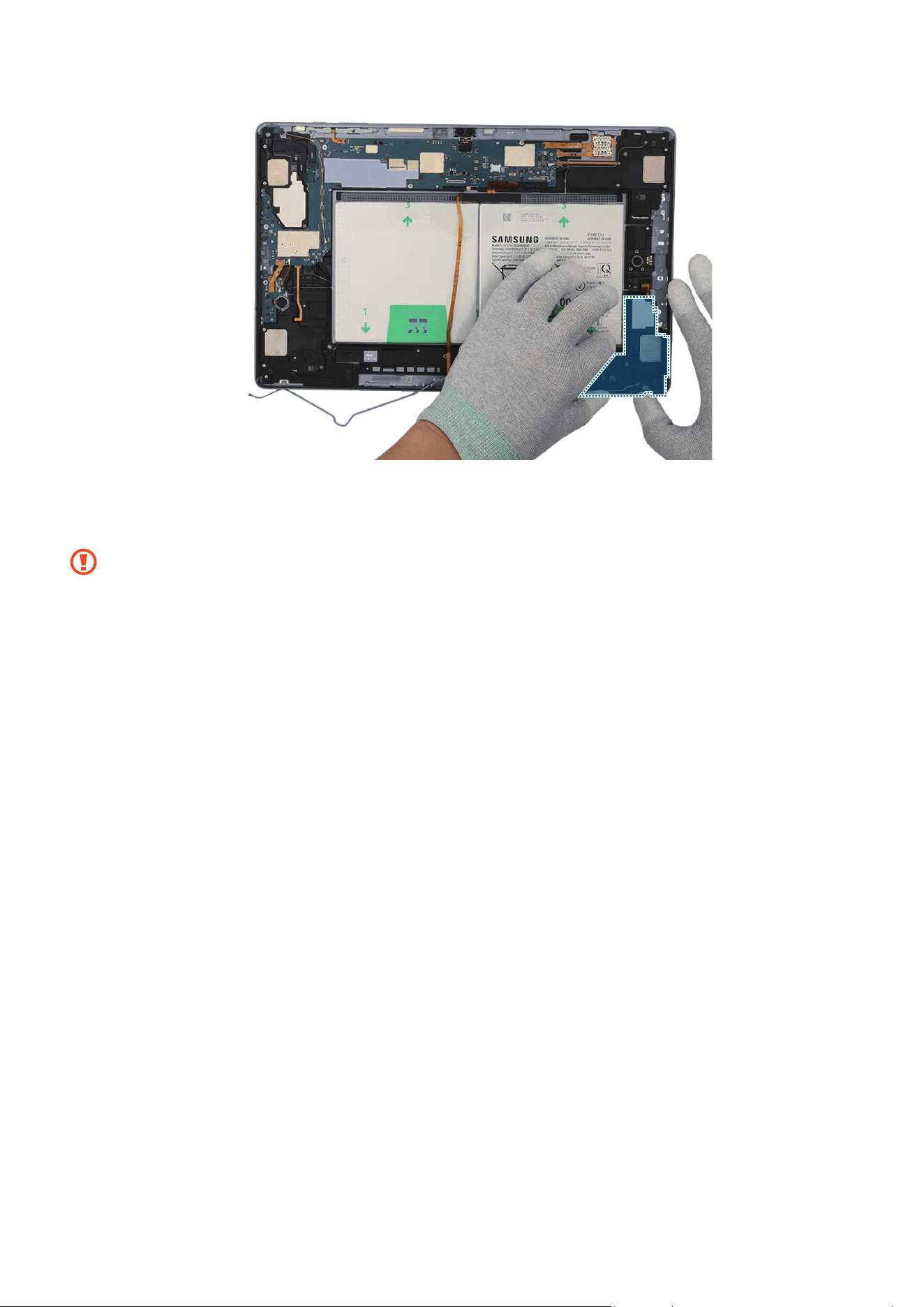
Disassembly and Assembly
215
6 Using your fingers, press down softly and evenly on the speaker module and the FPCB
so that the speaker module can be completely attached.
Be careful not to damage the speaker and FPCB.
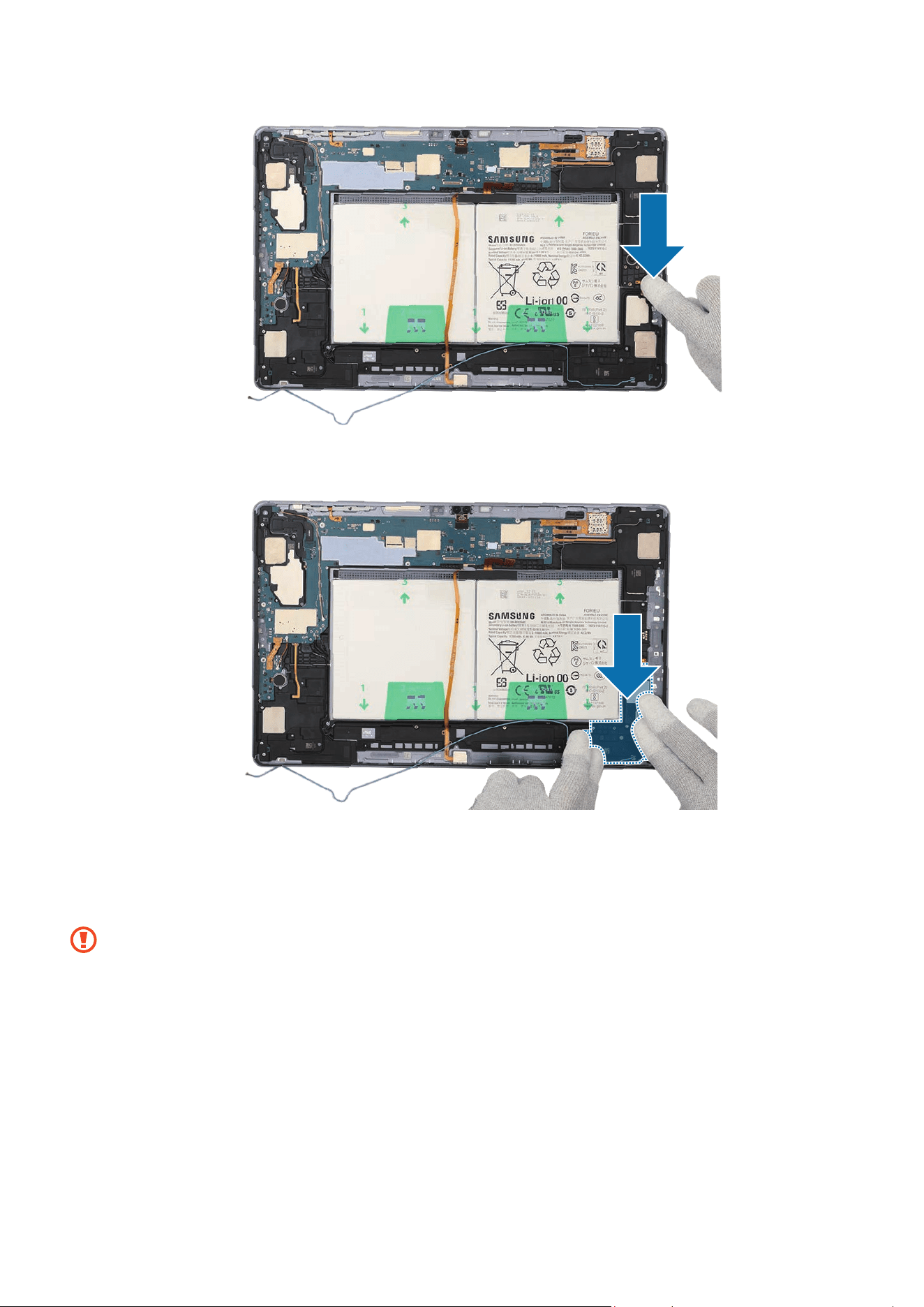
Disassembly and Assembly
216
7 Using the tweezers or your fingers, assemble the charging port to the back cover
module and press down softly and evenly on it so that the charging port can be
completely attached.
•
Be careful not to damage the charging port module side contact.
•
Be careful not to damage the near components.
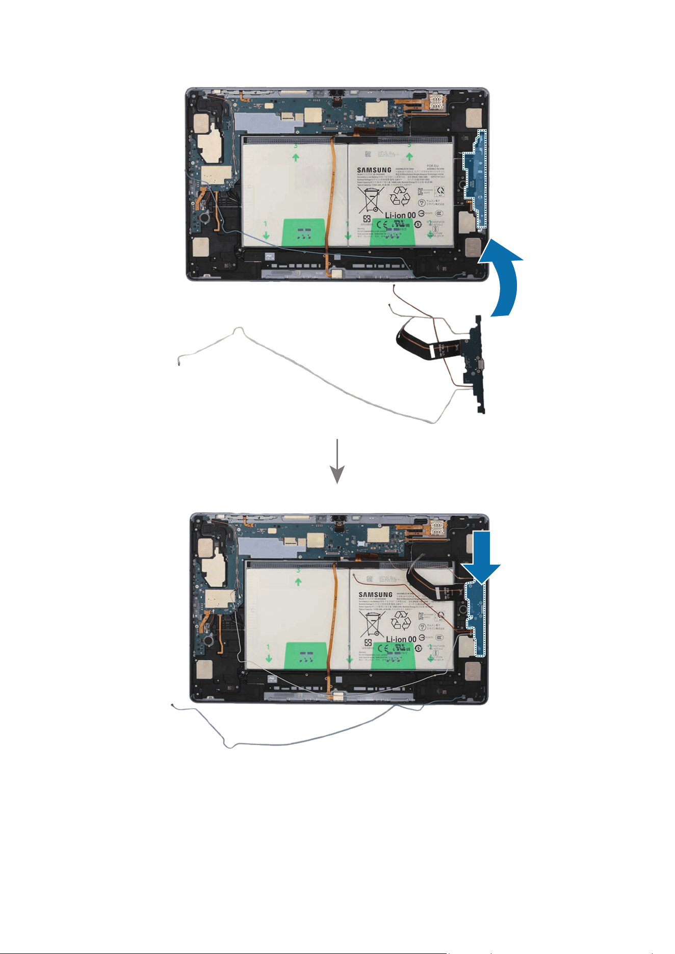
Disassembly and Assembly
217
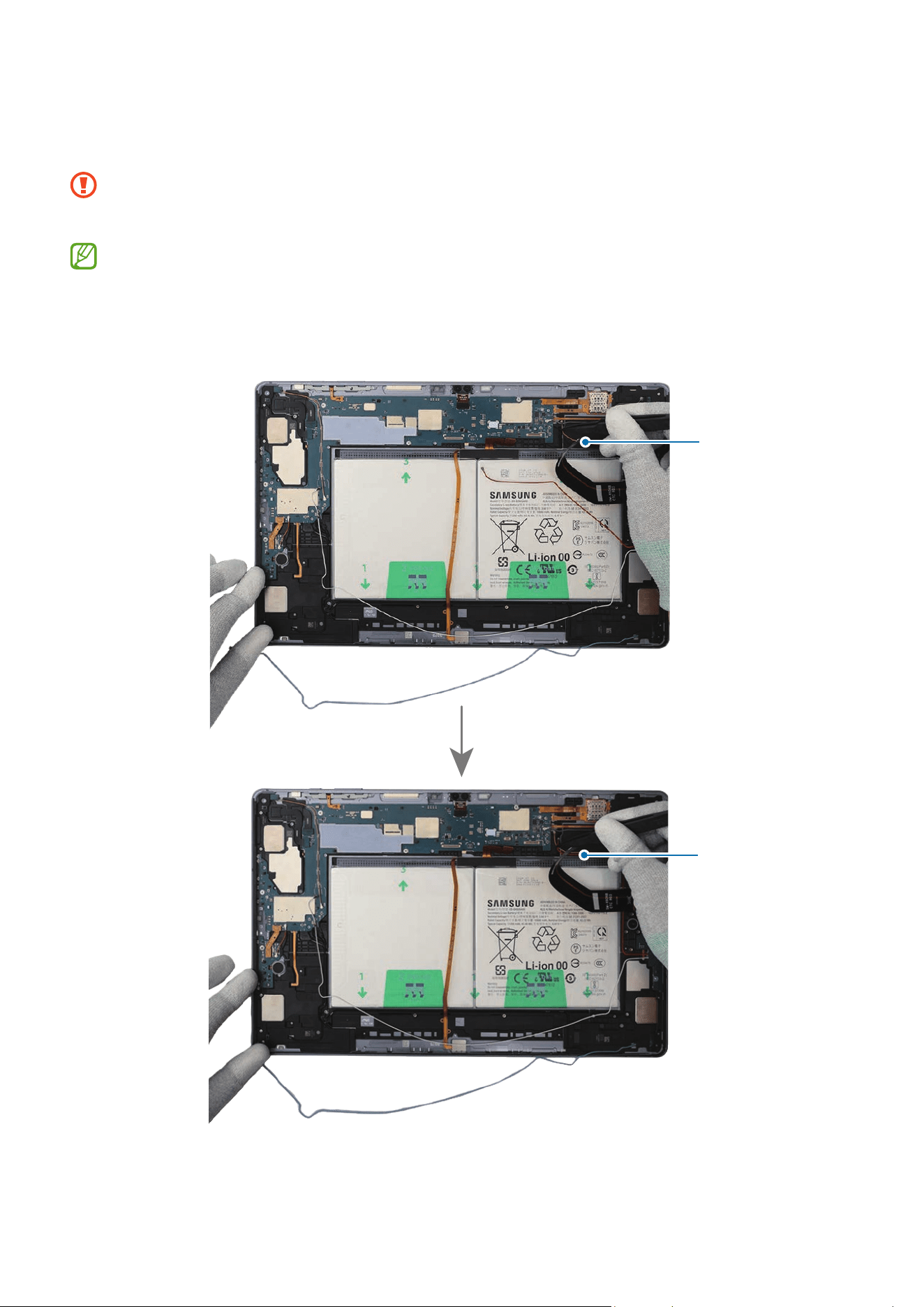
Disassembly and Assembly
218
8 For the 5G or LTE devices, connect the 4 coaxial cables (Orange/Red/White/Blue) to
the speaker modules.
•
Be careful not to damage the charging port and near components.
•
Be careful not to damage the cables.
•
The 4 coaxial cables (Orange/Red/White/Blue) are only available for the 5G or
LTE devices.
•
The cables and connectors may vary depending on the country, region, or
specifications.
Coaxial cable
(Orange)
Coaxial cable
(Red)
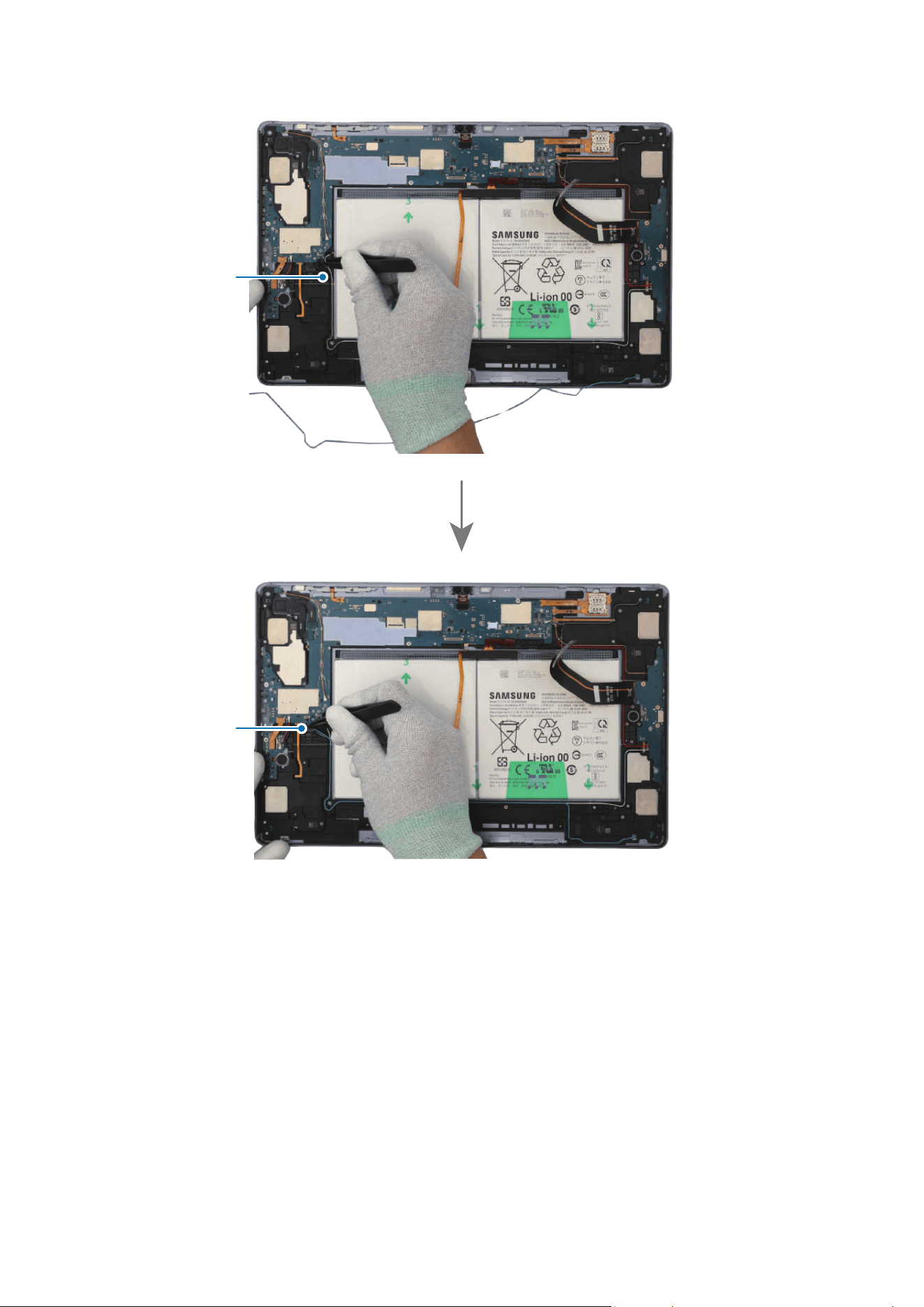
Disassembly and Assembly
219
Coaxial cable
(White)
Coaxial cable
(Blue)
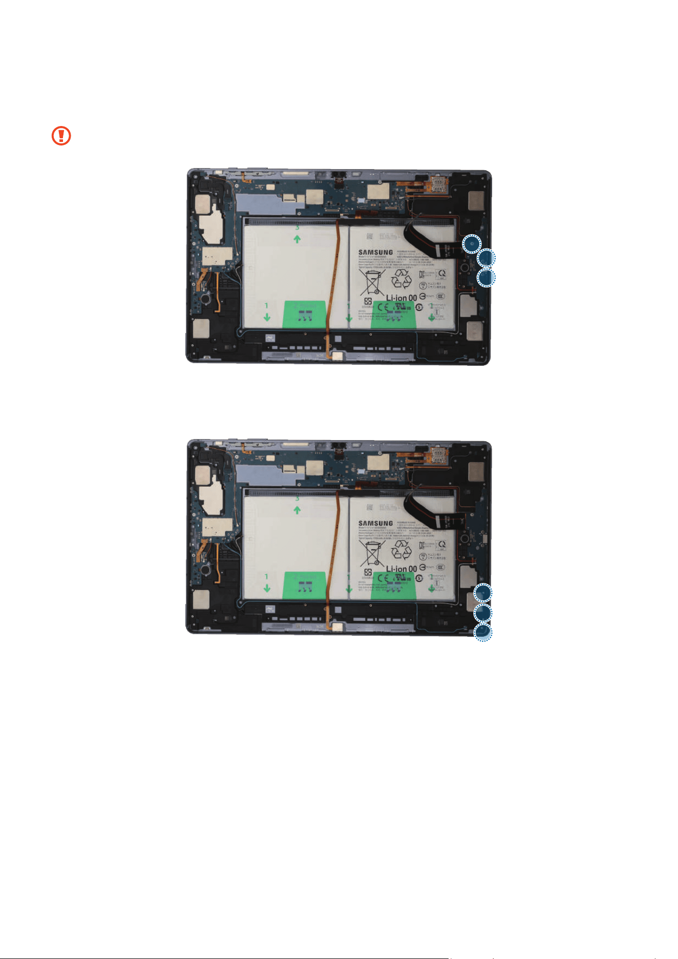
Disassembly and Assembly
220
9 Check the screw 3443 (3 ea) and fasten them on the charging port using a cross-head
screwdriver.
Be careful not to damage the charging port and near components.
10
Check the screw 3405 (3 ea) and fasten it on the speaker using a cross-head
screwdriver.
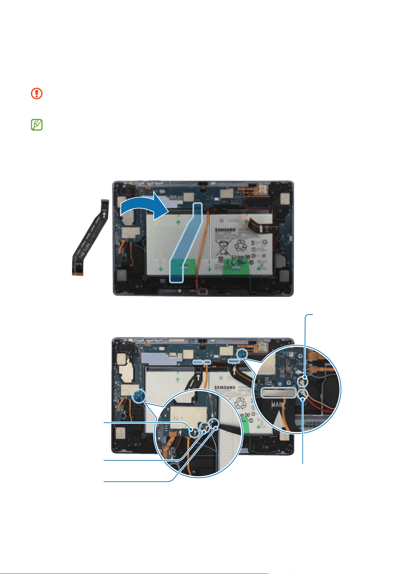
Disassembly and Assembly
221
11
Using the tweezers, connect the 3 connectors and the coaxial cable connector (Black)
to the main board. For the 5G or LTE devices, connect the additional 4 coaxial cable
connectors (Blue/White/Orange/Red).
•
Be careful not to damage the cable while connecting the connector.
•
Be careful not to damage the near components.
•
The 4 coaxial cables (Blue/White/Orange/Red) are only available for the 5G or
LTE devices.
•
The cables and connectors may vary depending on the country, region, or
specifications.
Coaxial cable (Red)
Coaxial cable
(White)
Coaxial cable
(Blue)
Coaxial cable
(Orange)
Coaxial cable
(Black)

Disassembly and Assembly
223
Battery
•
The battery can only be replaced at an authorised repair shop. If the battery is
faulty, contact Samsung for further action.
•
The separate battery may be damaged. Do not use it again.
Disassembly
Remove the Screen and Bracket first before you begin.
1 Using the tweezers, disconnect the battery connector from the main board first.
Separate the 3 connectors from the main board.
•
Make sure to first disconnect the battery connector for your own safety.
•
Be careful not to damage the battery.
•
Be careful not to damage the cable while removing the connector.
•
Be careful not to damage the near components.
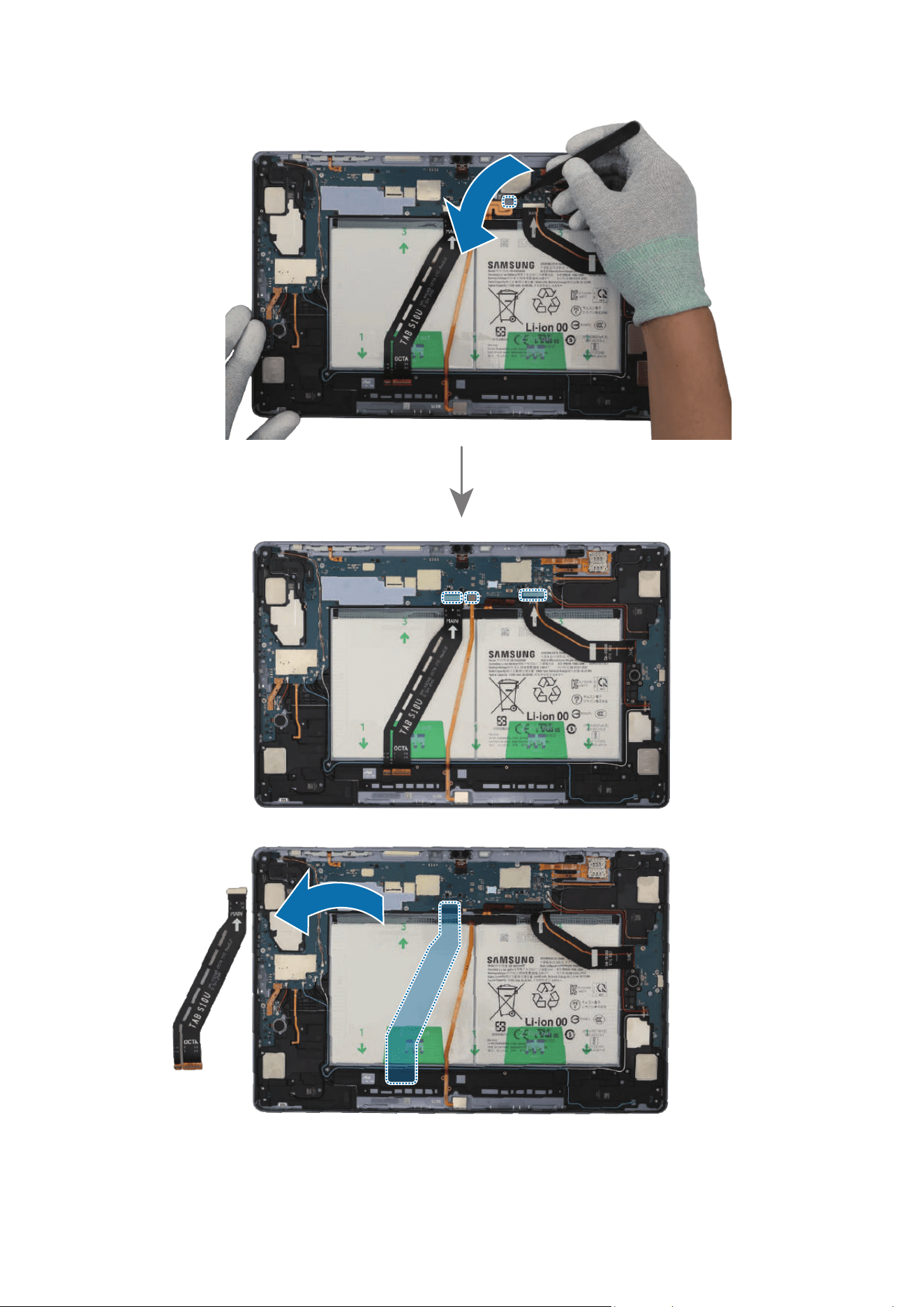
Disassembly and Assembly
224
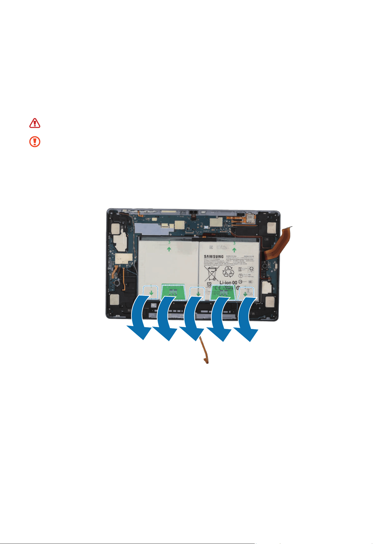
Disassembly and Assembly
225
2 Using your fingers, grab the tapes attached to the bottom of the battery and separate
them carefully from the battery. Grab the tapes (marked as 2) with your fingers
and pull it up one by one carefully. Slowly lift up the battery from the device and
separate the bottom of the battery first. Using your fingers, hold the tapes (marked
as 3) attached to the top of the battery and separate them from the battery. Grab the
separated battery with your fingers and remove it completely from the device.
The separated battery may be damaged. Do not use it again.
•
As the adhesive securing the battery is very strong, remove the battery slowly
and carefully.
•
The FPCB cables and connectors have to positioned outside so as not to
interfere when disassembling the battery.
•
Be careful not to damage the connectors and near components.
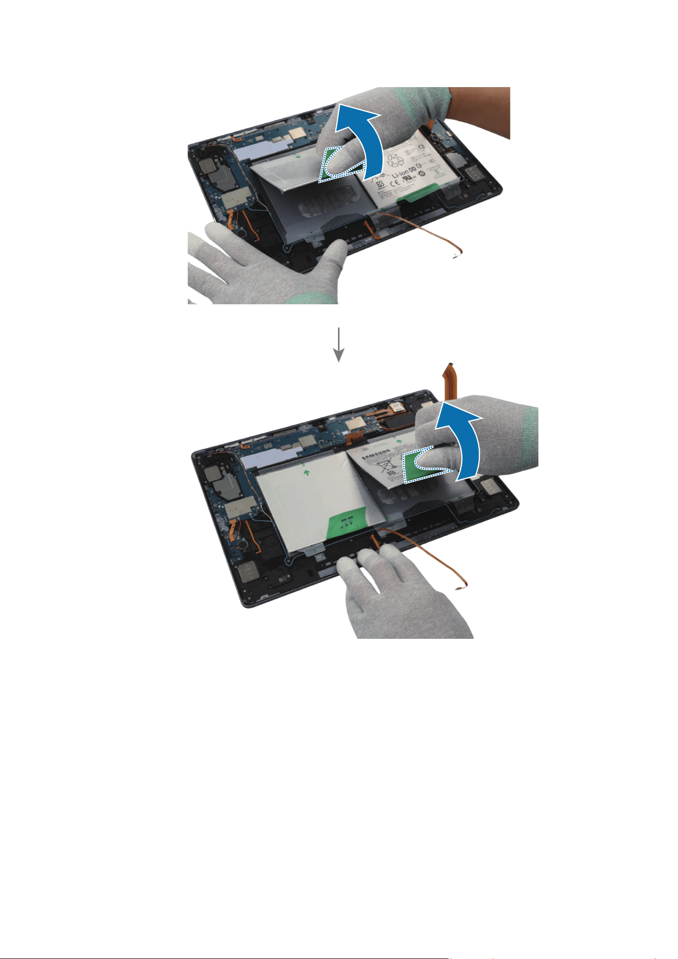
Disassembly and Assembly
226
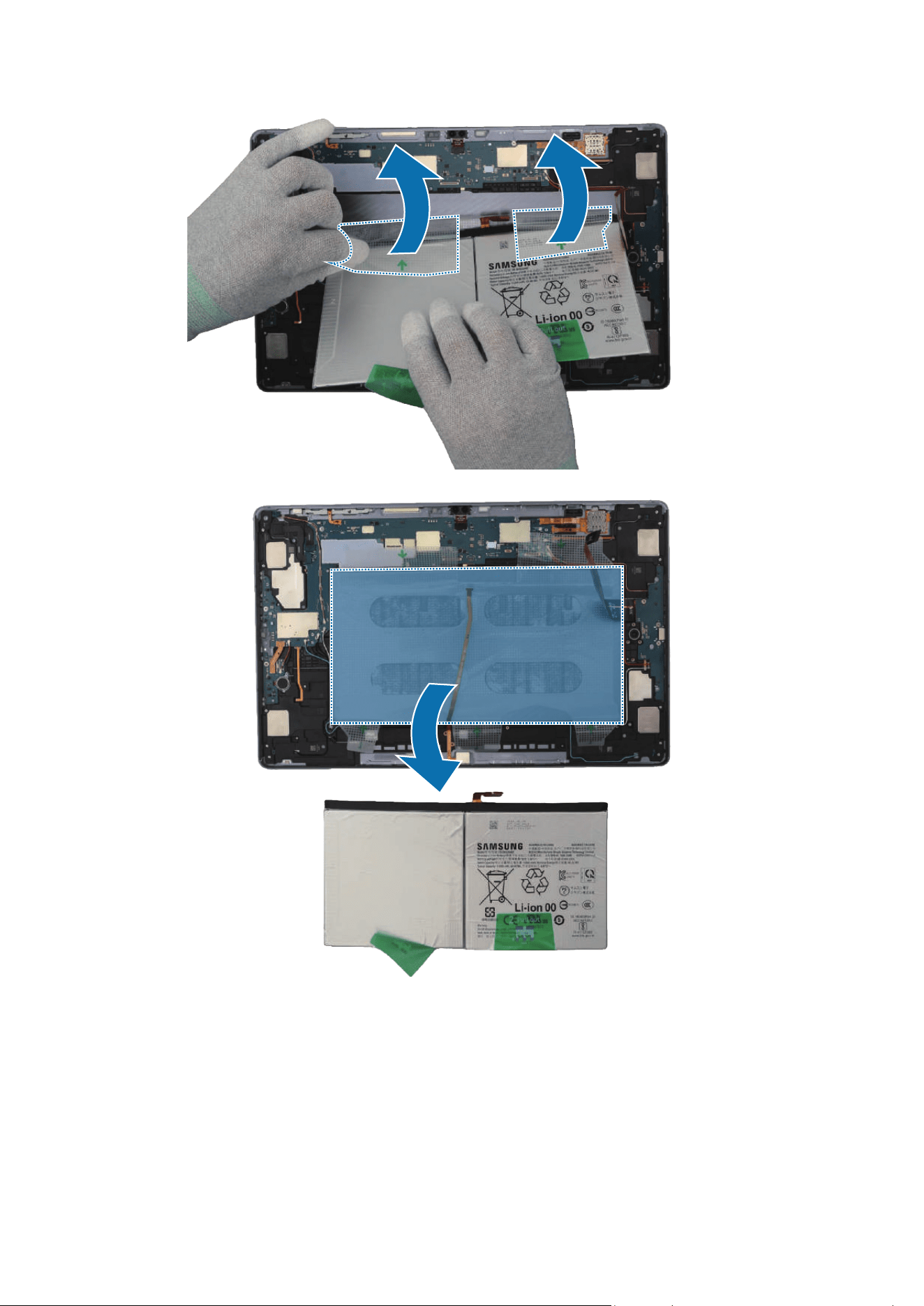
Disassembly and Assembly
227
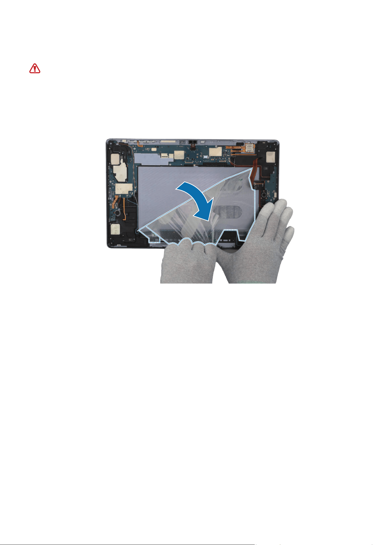
Disassembly and Assembly
228
Reassembly
Leaving screws inside the device may damage internal components, such as the
battery. When assembling, be extra careful not to leave any unassembled screws
inside the device.
1 Using your fingers, carefully separate the tape attached under the battery and lift it
up slowly. Then, remove it completely from the device.
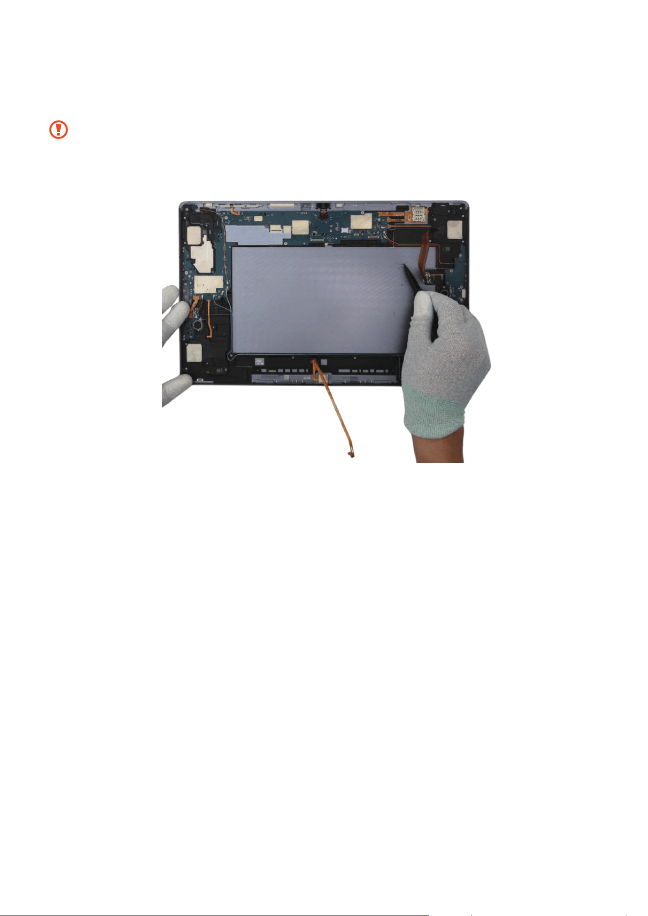
Disassembly and Assembly
229
2 Using the tweezers, remove the remaining adhesive tapes from where the battery
was attached.
•
Make sure to remove any residual tapes attached to the inside of the back cover
module before reassembling the new battery.
•
Be careful not to damage the device and near components.
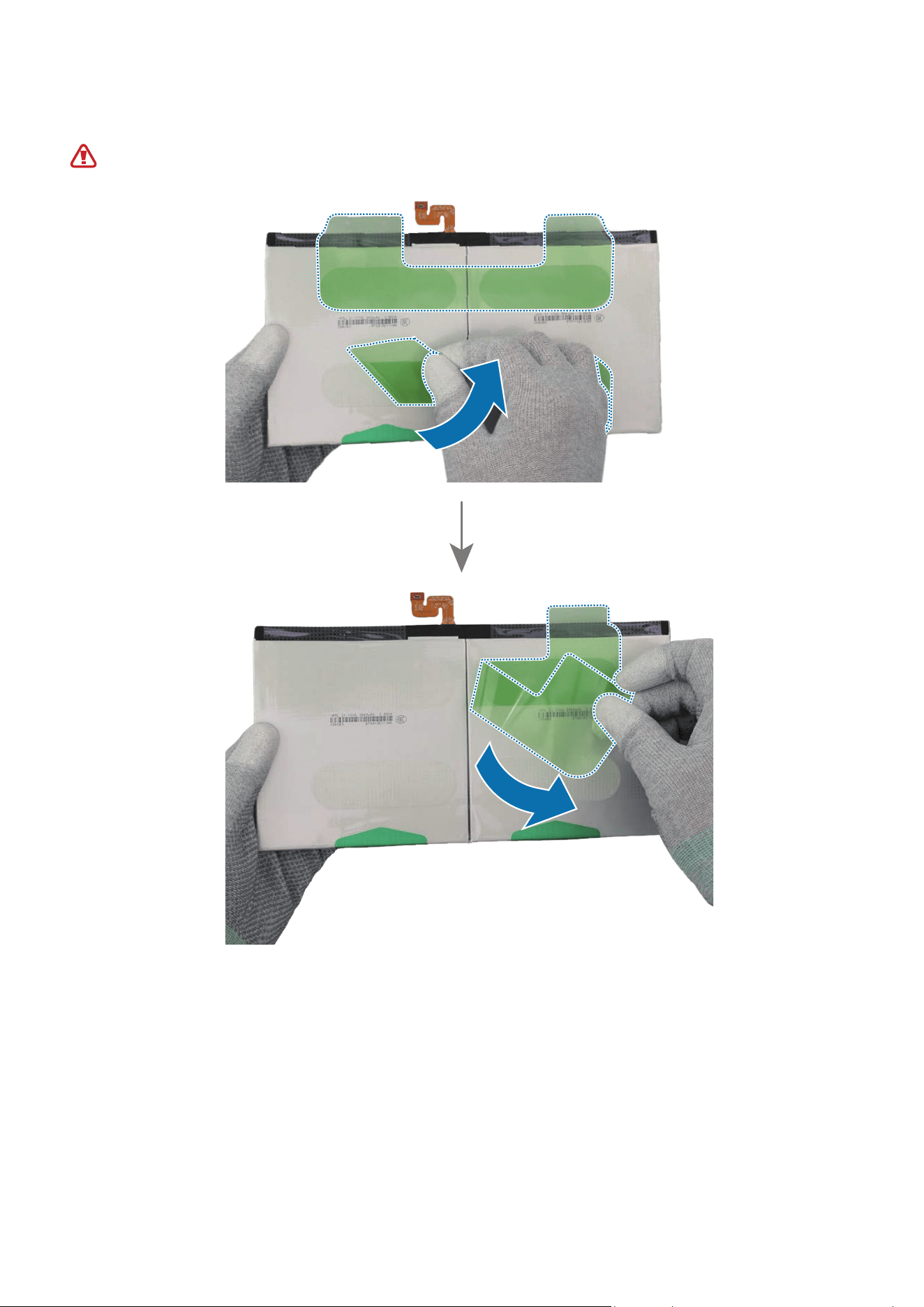
Disassembly and Assembly
230
3 Using your fingers, carefully remove all release films from the new battery.
Be careful not to damage the battery.
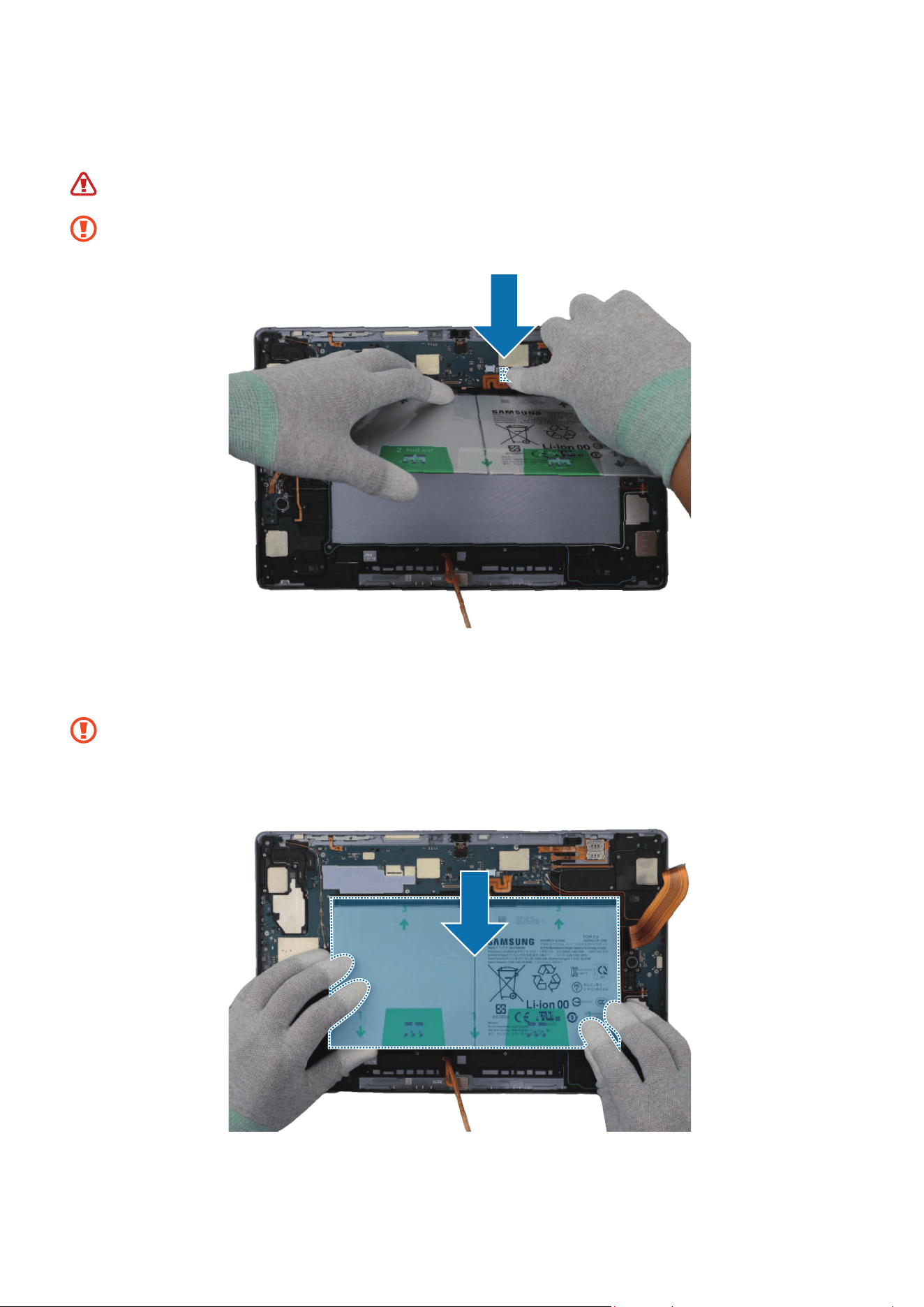
Disassembly and Assembly
231
4 Before attaching the battery to the back cover module, connect the battery connector
to the main board first using your fingers.
Be careful not to damage the battery.
Be careful not to damage the battery connector and near components.
5 With the battery connector connected to the main board, assemble the battery in the
correct position of the back cover module using your fingers.
•
The FPCB cables have to positioned outside so as not to interfere when
assembling the battery.
•
Be careful not to damage the near components.
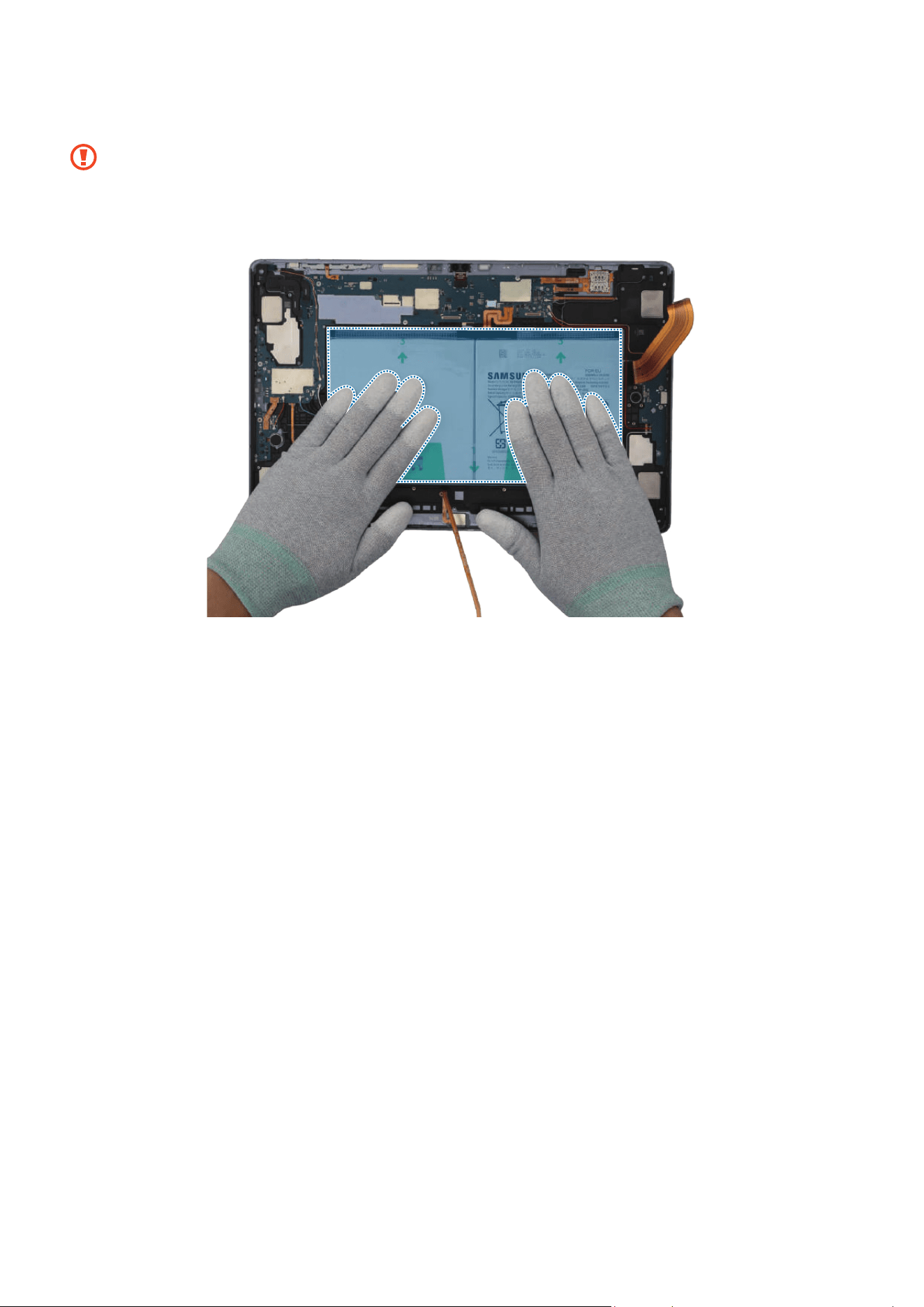
Disassembly and Assembly
232
6 Press the battery with your fingers softly so that the battery can be attached well.
•
The FPCB cables have to positioned outside so as not to interfere when
assembling the battery.
•
Be careful not to damage the near components.
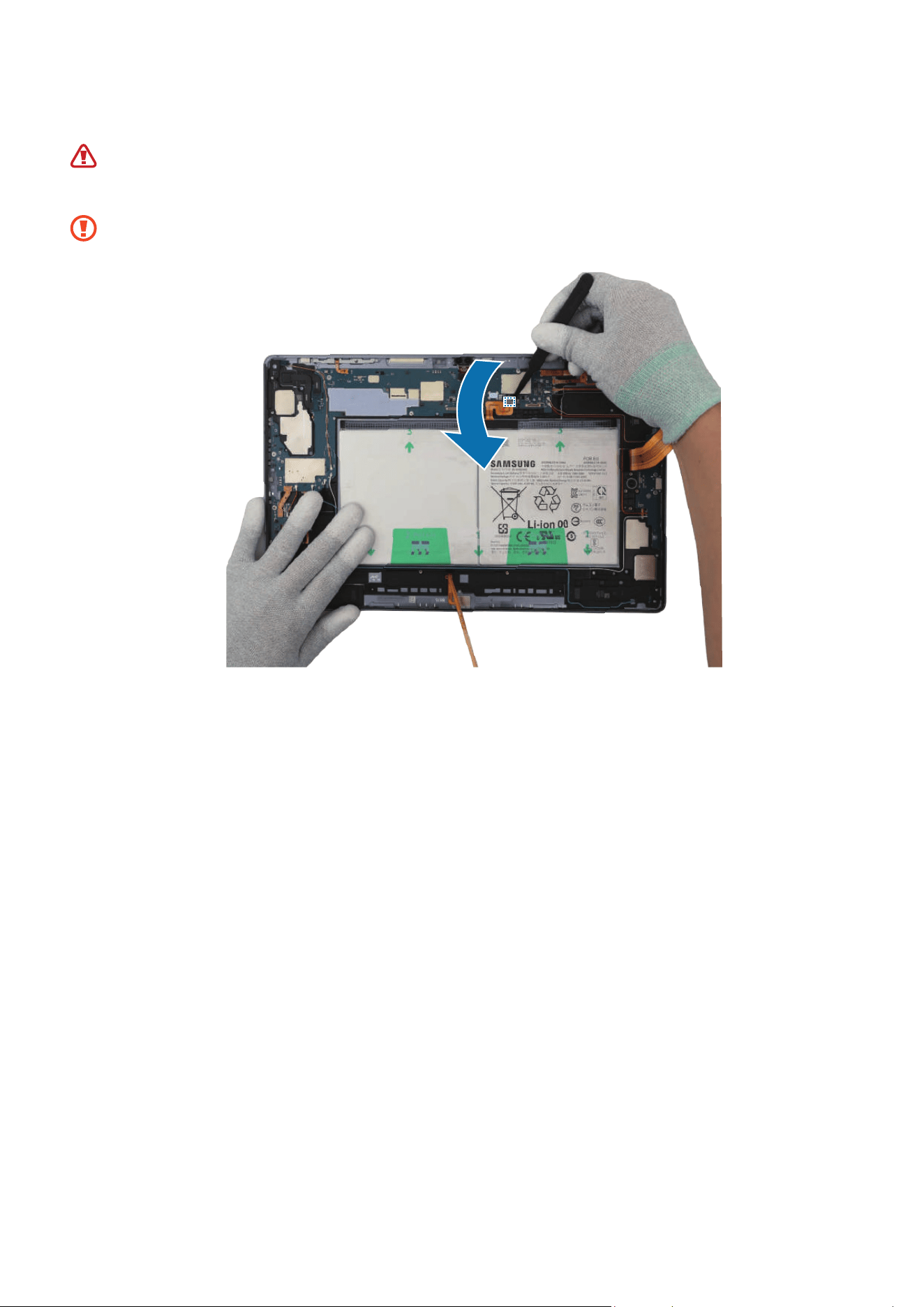
Disassembly and Assembly
233
7 Using the tweezers, disconnect the battery connector from the main board.
•
Make sure to first disconnect the battery connector for your own safety.
•
Be careful not to damage the battery.
Be careful not to damage the battery connector and near components.
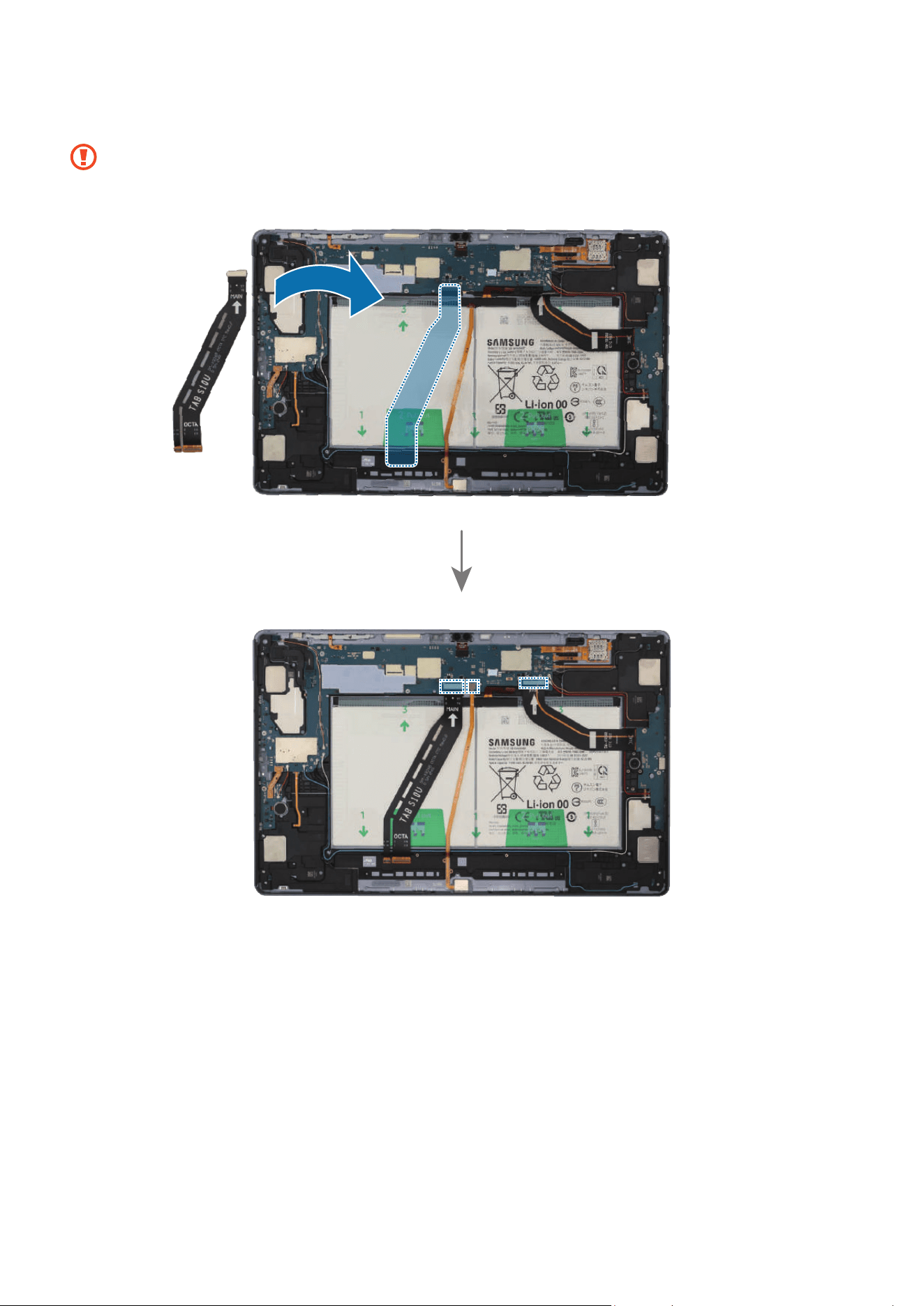
Disassembly and Assembly
234
8 Using the tweezers, connect the 3 connectors to the main board.
•
Be careful not to damage the cable while connecting the connector.
•
Be careful not to damage the main board and near components.

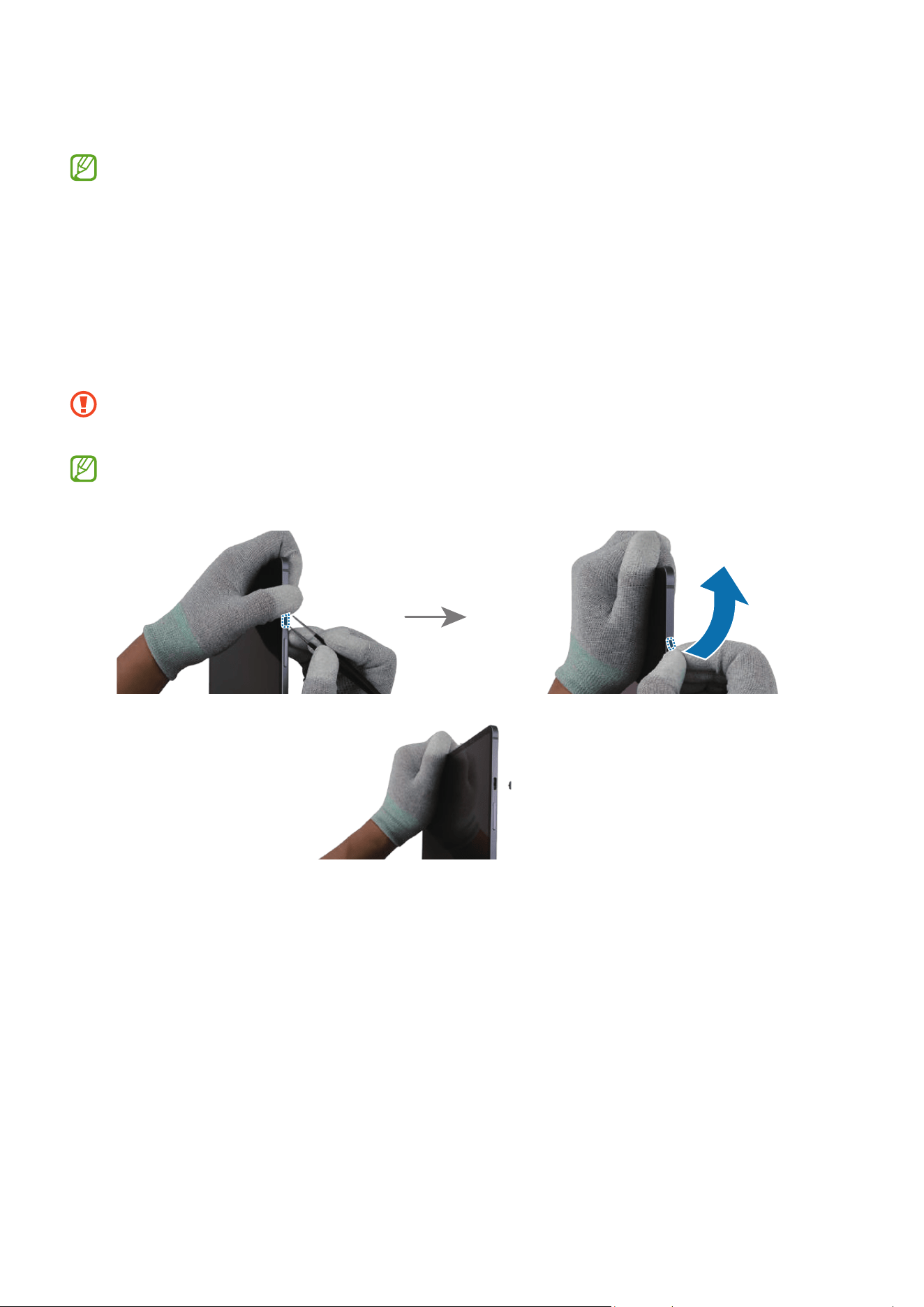
Disassembly and Assembly
236
Button
The buttons are already built into the back cover module. Disassemble the buttons
only if the buttons themselves require repairs.
Disassembly
To remove the Volume button or Side button, lightly press one end of the button with
your fingers so that the other end protrudes. Push the tip of the protruding button up
carefully with the round-tip metal tweezers and lift it up until you can grab it with your
fingers. Grab the button with your fingers and pull it out carefully from the device.
When holding the buttons with the tweezers, be careful not to damage or scratch
the device.
If you have trouble separating the buttons with your tweezers, please try using a
sharper and thinner tool.
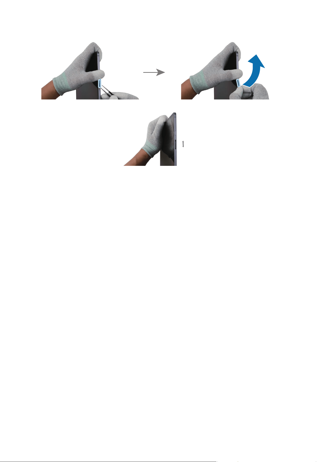
Disassembly and Assembly
237
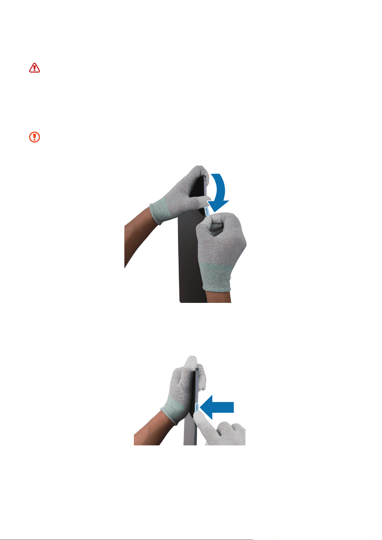
Disassembly and Assembly
238
Reassembly
Leaving screws inside the device may damage internal components, such as the
battery. During assembly, be extra careful not to leave any unassembled screws
inside the device.
1 Remove the release film of a new Volume button. Using your fingers, grab the Volume
button and insert it on the slot carefully.
•
Be careful not to damage the button and device.
•
Be careful not to put the button in the wrong direction.
2 Press down the Volume button softly and evenly so that the button can be completely
assembled. Press the button to make sure it clicks. It should have the same sound
and feel as before disassembly.
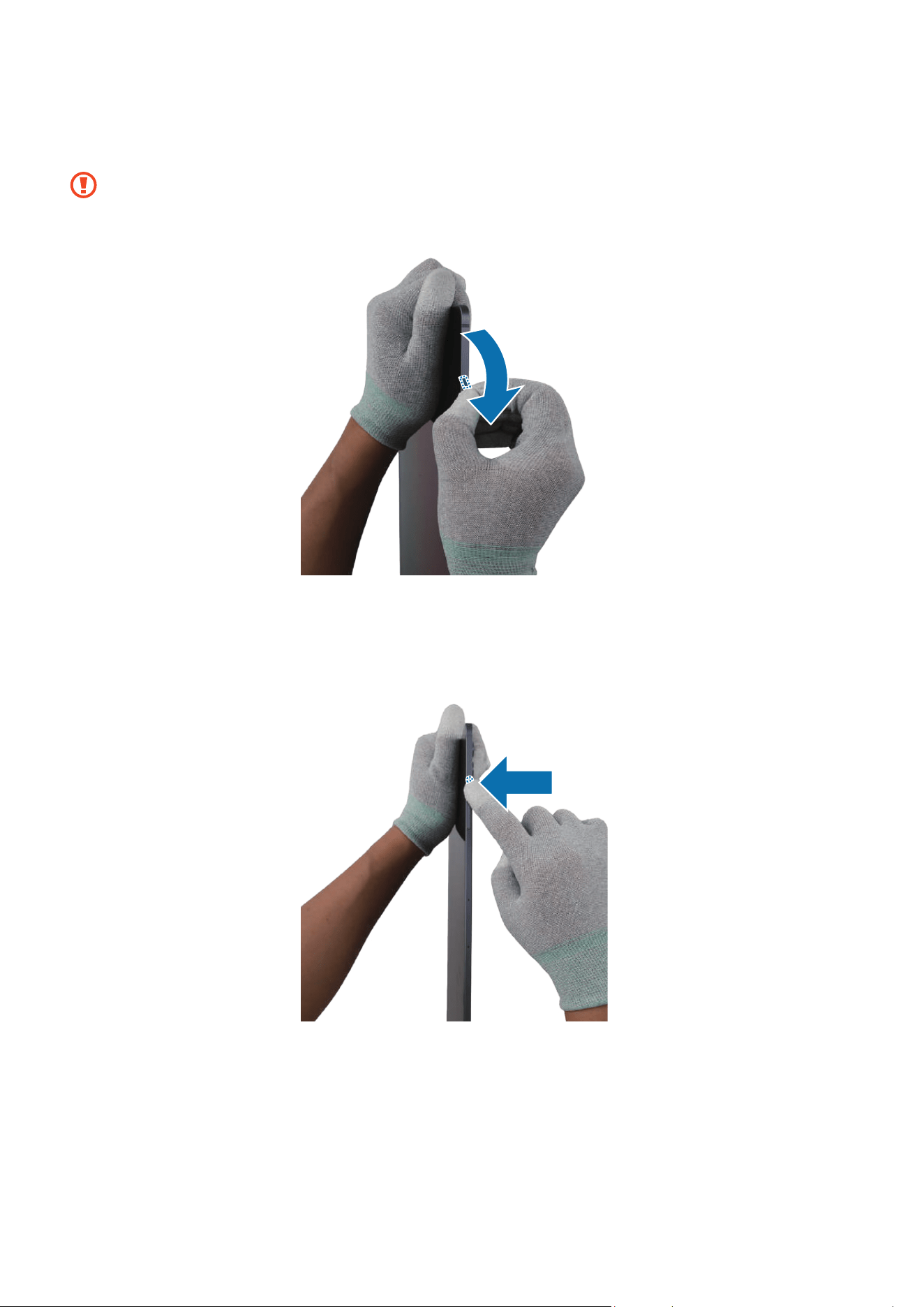
Disassembly and Assembly
239
3 Remove the release film of a new Side button. Using your fingers, grab the Side
button and insert it on the slot carefully.
•
Be careful not to damage the button and device.
•
Be careful not to put the button in the wrong direction.
4 Press down the Side button softly and evenly so that the button can be completely
assembled. Press the button to make sure it clicks. It should have the same sound
and feel as before disassembly.

Disassembly and Assembly
240
Back Cover
Disassembly
Remove the SIM Card Tray, Screen and Bracket first before you begin.
1 Using the tweezers, disconnect the battery connector from the main board first.
Separate the 8 connectors and the 3 coaxial cable connectors (Orange/Black/Red)
from the main board. For the 5G or LTE devices, separate the additional 5 coaxial
cable connectors (Blue/White/Grey/Orange/Red).
•
Make sure to first disconnect the battery connector for your own safety.
•
Be careful not to damage the battery.
•
Be careful not to damage the cable while removing the connector.
•
Be careful not to damage the near components.
•
The 5 coaxial cables (Blue/White/Grey/Orange/Red) are only available for the
5G or LTE devices.
•
The cables and connectors may vary depending on the country, region, or
specifications.

Disassembly and Assembly
241

Disassembly and Assembly
242
Coaxial cable
(White)
Coaxial cable
(Blue)
Coaxial cable
(Grey)
Coaxial cable (Red)
Coaxial cable
(Orange)
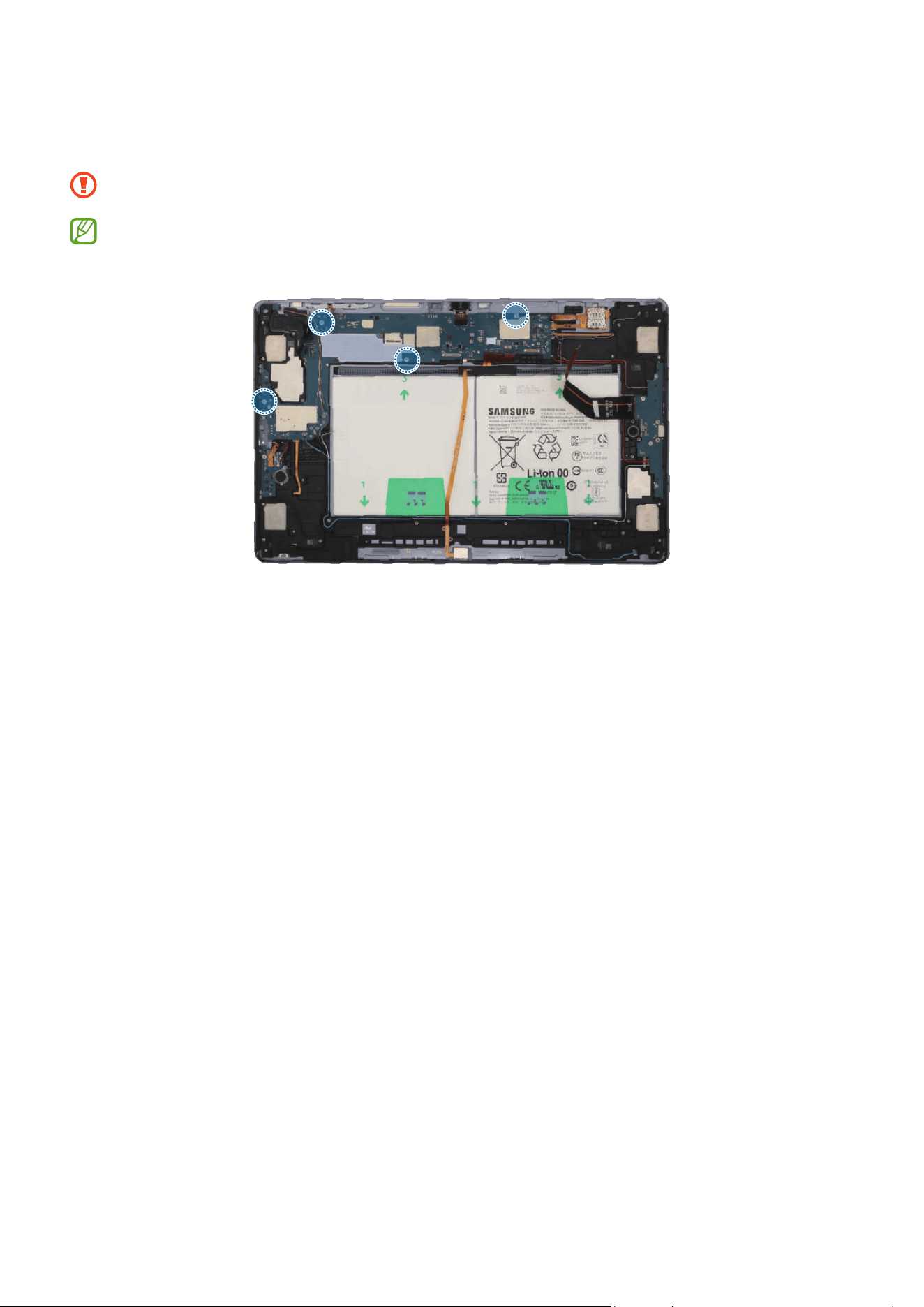
Disassembly and Assembly
243
2 Check and remove the screws at the 4 different points on the main board using a
cross-head screwdriver.
Be careful not to damage the main board and near components.
Check the number of screws that have been removed, and store them carefully to
make sure that no unassembled screws are left inside the device during assembly.

Disassembly and Assembly
244
3 Using the tweezers, disconnect the coaxial cable (Orange) from the main board. Then,
lift up on the separator groove of the main board and remove the main board module.
•
Be careful not to damage the battery connector, the main board and near
components.
•
The cables have to positioned outside so as not to interfere when disassembling
the main board.
Coaxial cable
(Orange)
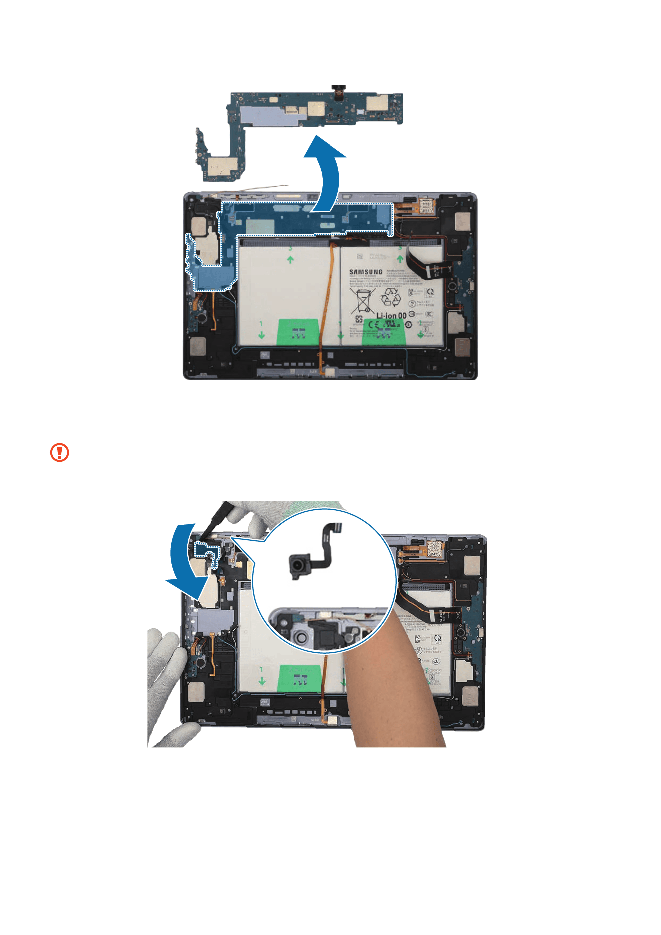
Disassembly and Assembly
245
4 Using the tweezers, lift up on the separator groove of the ultra wide camera first and
remove it. Leave the camera lens facing up.
•
Be careful not to touch the camera lens while removing the camera.
•
Be careful not to damage the camera and near components.
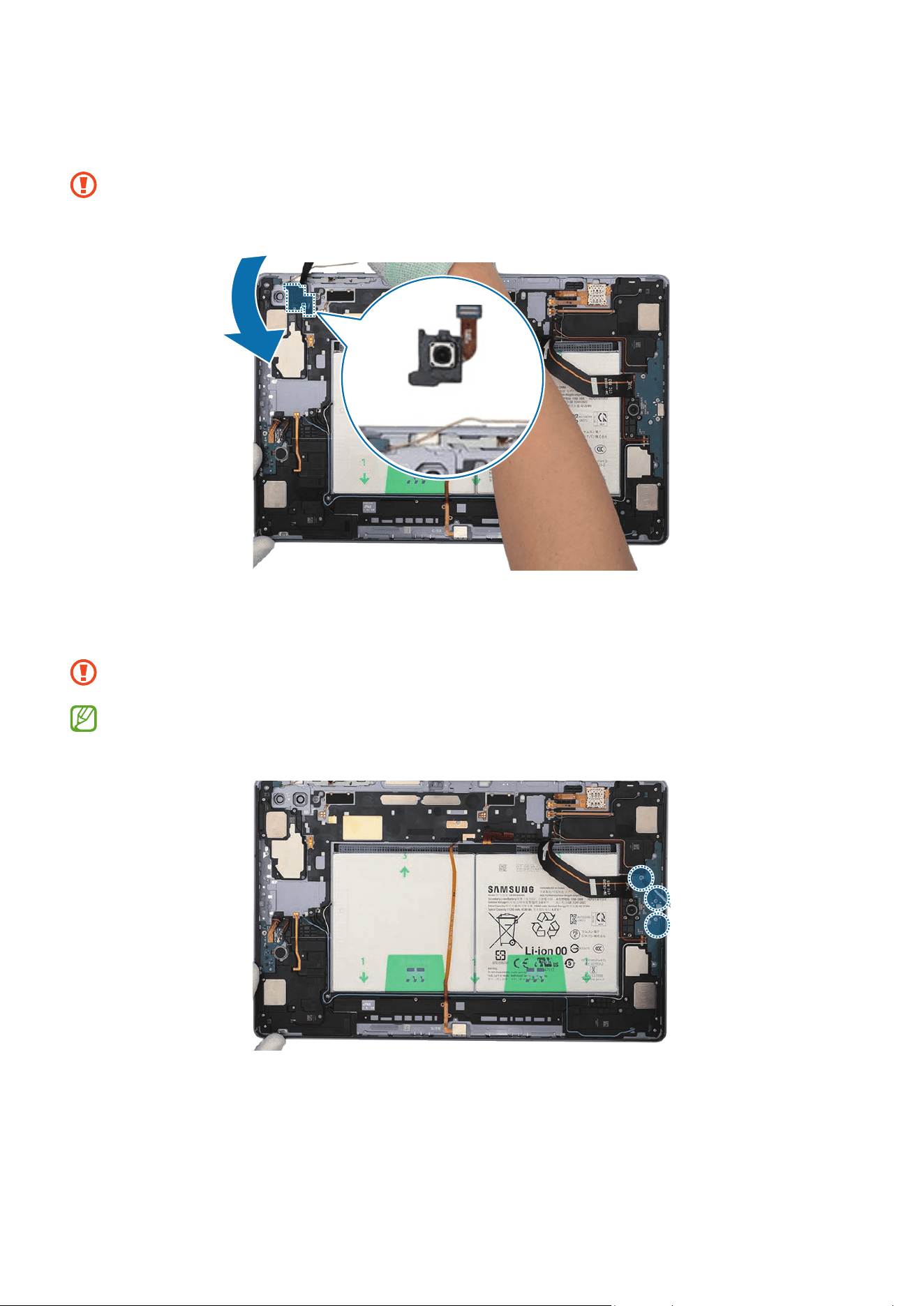
Disassembly and Assembly
246
5 Using the tweezers, lift up on the separator groove of the wide camera and remove it.
Leave the camera lens facing up.
•
Be careful not to touch the camera lens while removing the camera.
•
Be careful not to damage the camera and near components.
6 Check the screws at the 3 different points on the charging port and remove them
using a cross-head screwdriver.
Be careful not to damage the charging port and near components.
Check the number of screws that have been removed, and store them carefully to
make sure that no unassembled screws are left inside the device during assembly.
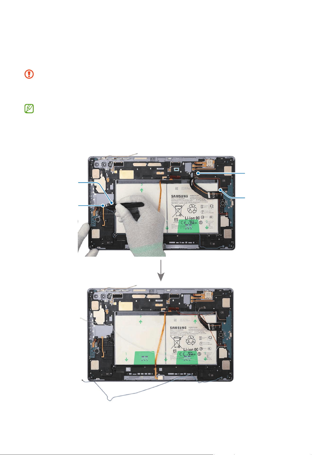
Disassembly and Assembly
247
7 For the 5G or LTE devices, disconnect the 4 coaxial cables (Blue/White/Orange/
Red) in the speaker modules with the tweezers. Using the tweezers, lift up on the
separator groove of the charging port module, and remove it carefully.
•
Check the position of the overlapping cables and disconnect them in order from
the top.
•
Be careful not to damage the cables and near components.
•
The 4 coaxial cables (Blue/White/Orange/Red) are only available for the 5G or
LTE devices.
•
The cables and connectors may vary depending on the country, region, or
specifications.
Coaxial cable
(Red)
Coaxial cable
(Orange)
Coaxial cable
(White)
Coaxial cable
(Blue)
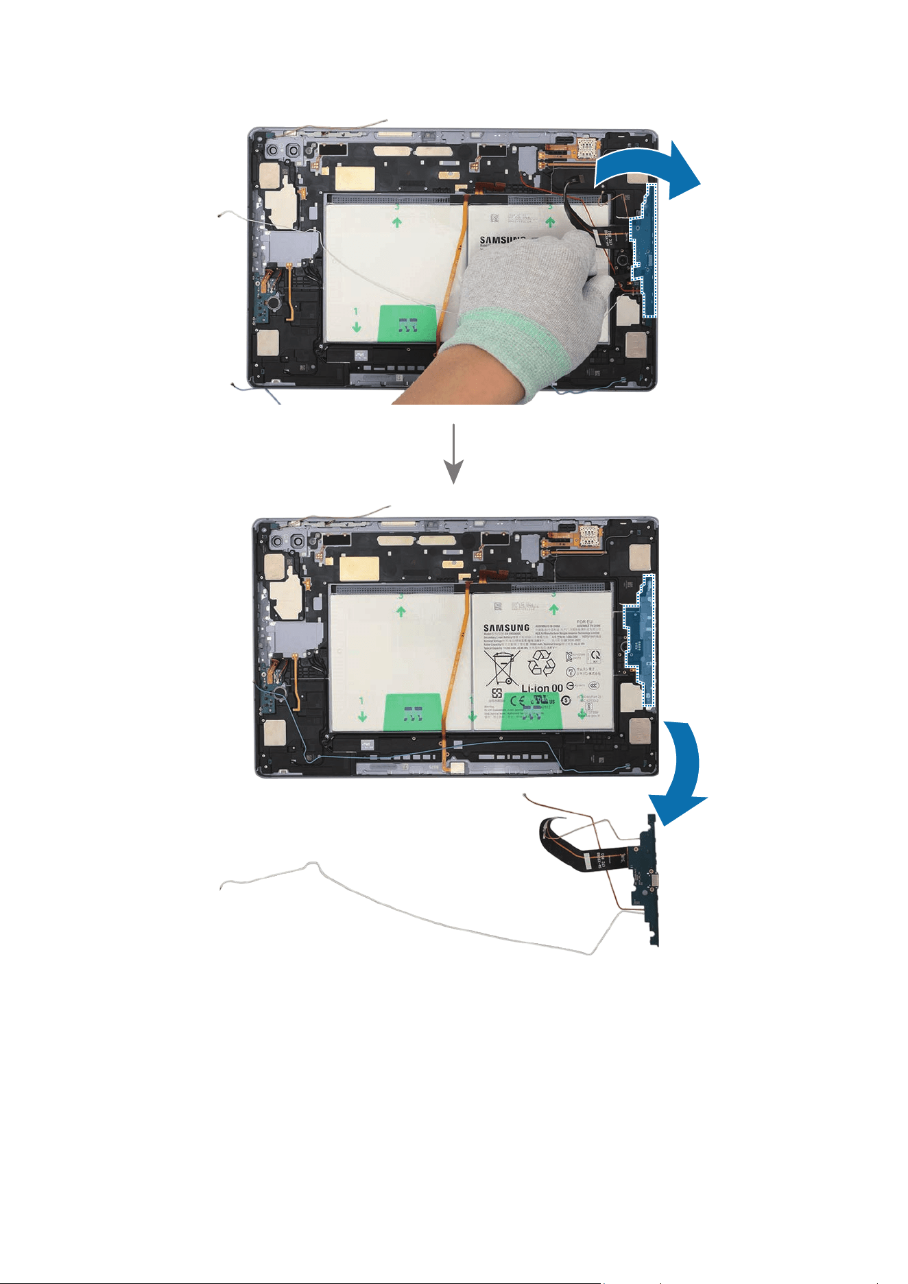
Disassembly and Assembly
248
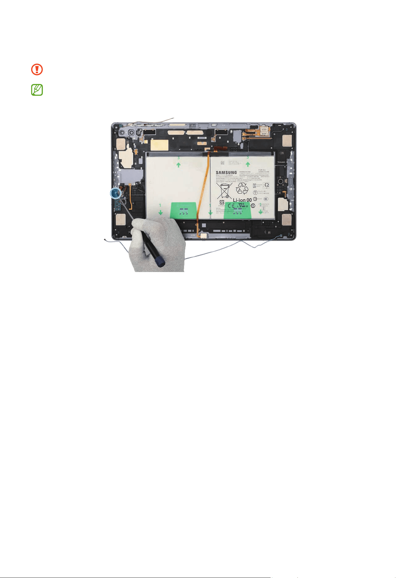
Disassembly and Assembly
249
8 Check the screw on the Wi-Fi board and remove it using a cross-head screwdriver.
Be careful not to damage the near components.
Check the number of screws that have been removed, and store them carefully to
make sure that no unassembled screws are left inside the device during assembly.
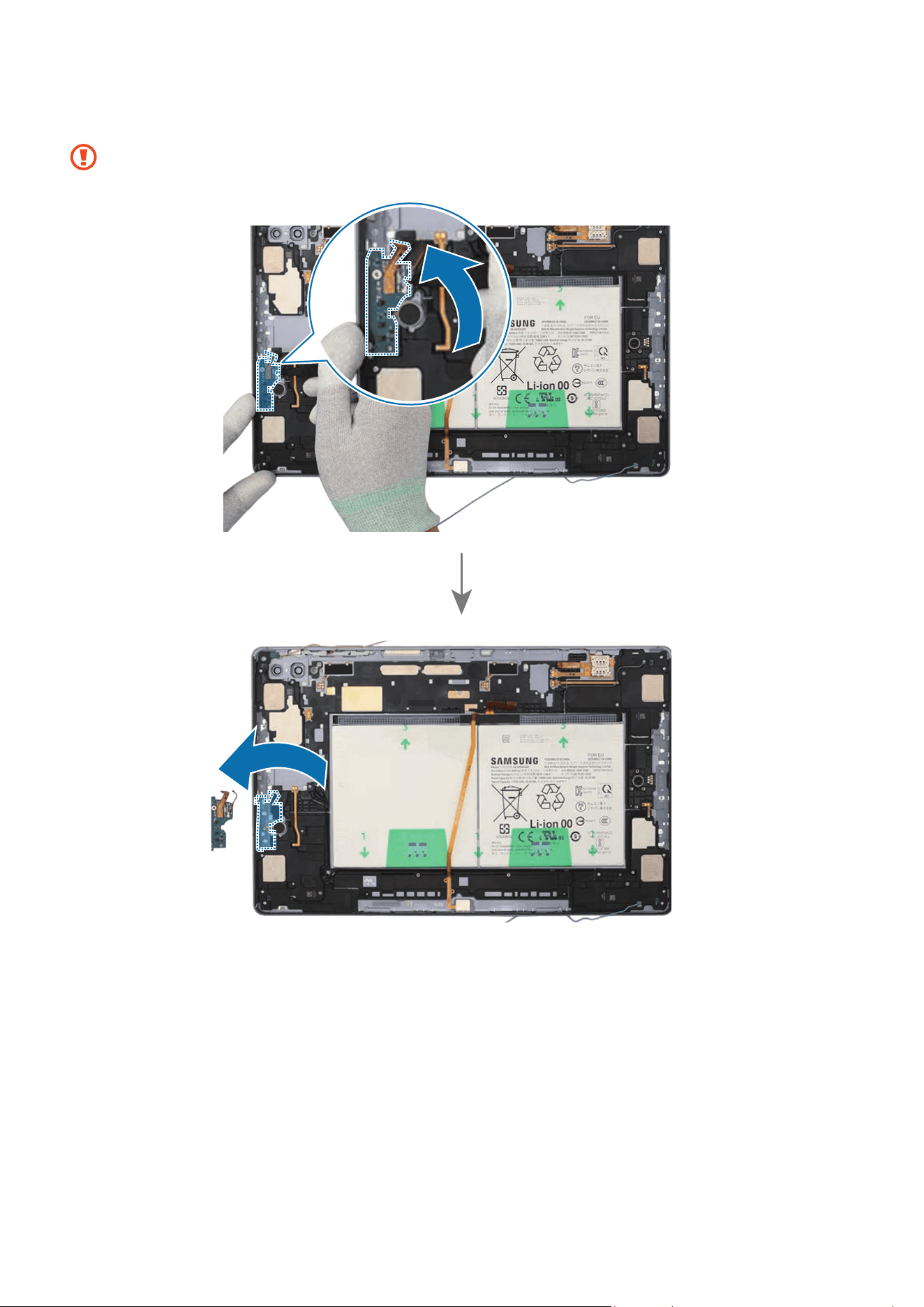
Disassembly and Assembly
250
9 Using the tweezers, lift up the Wi-Fi board from the back cover module and remove it.
Be careful not to damage the cables and near components.
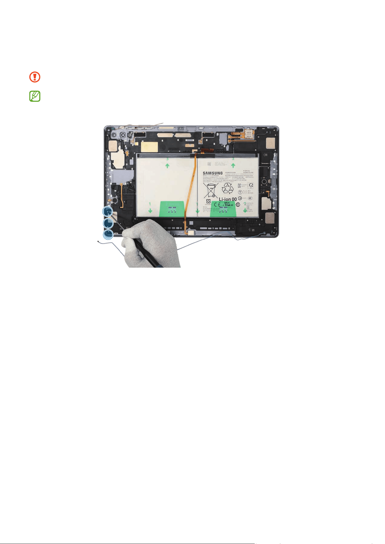
Disassembly and Assembly
251
10
Check the screws at the 3 different points on the speaker 1 and remove them using a
cross-head screwdriver.
Be careful not to damage the near components.
Check the number of screws that have been removed, and store them carefully to
make sure that no unassembled screws are left inside the device during assembly.
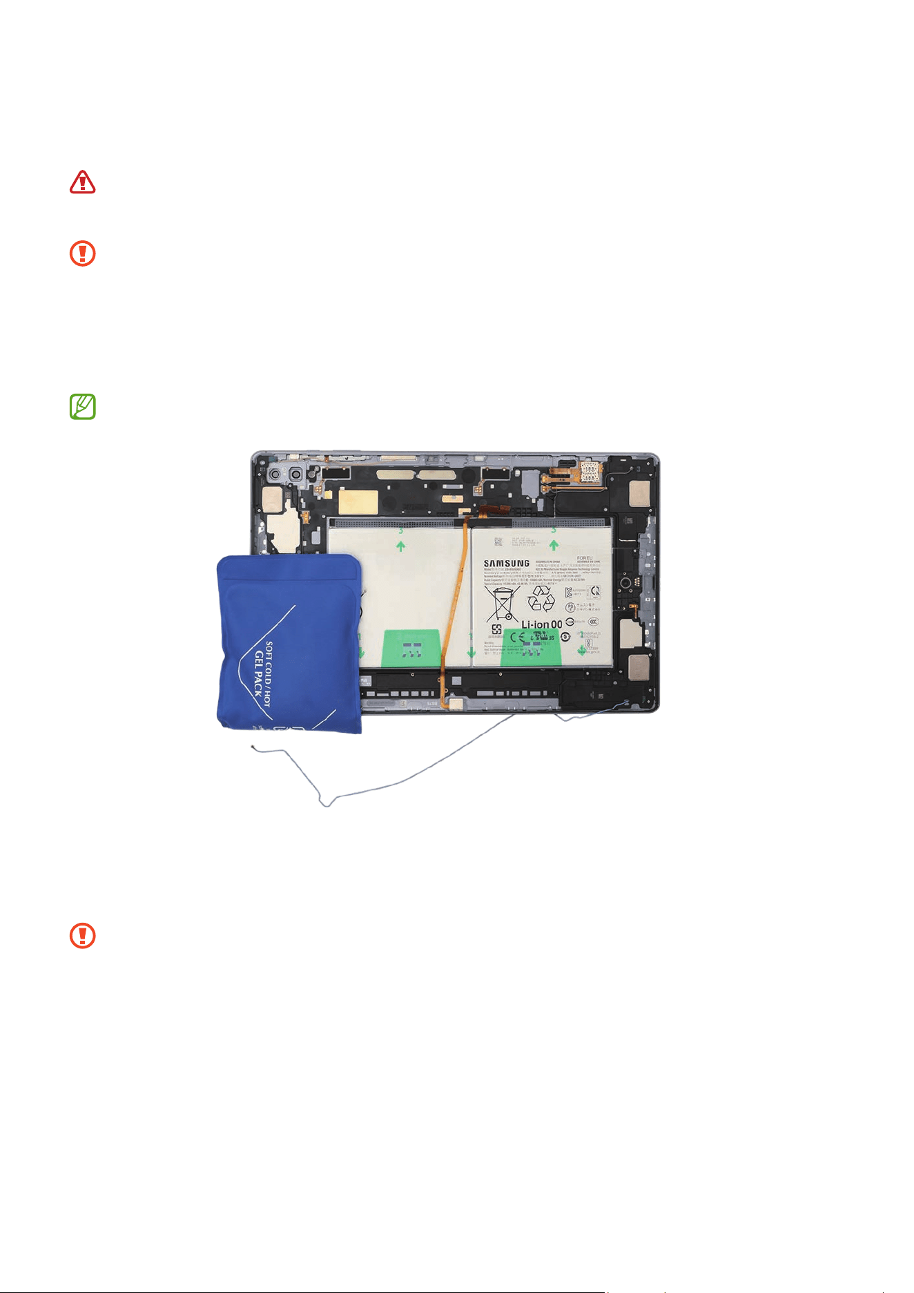
Disassembly and Assembly
252
11
Heat the microwaveable heating bag and apply it to the both front and back side of
the speaker 1 module for 4 minutes.
•
It is possible for the device or battery to be damaged by heat.
•
Do not heat the device in a microwave. Doing so could cause an explosion.
•
Follow the heating bag’s instructions for heating. The recommended time for
heating the bag is 50 seconds in a 1000 W microwave and 70 seconds in a 700 W
microwave. (Correct temperature for use: 55-65 ℃.)
•
Be careful not to damage the device through excessive heat. (It is
recommended to disassemble the device in an area with a temperature gauge.)
When reheating, it should be heated no longer than 30 seconds.
12
Using the tweezers, separate the FPCB of the speaker 1 module carefully. Insert the
tweezers into the separator groove of the speaker 1 and remove it from the back cover
module.
•
Be careful not to damage the speaker and cable.
•
Be careful not to damage the near components.
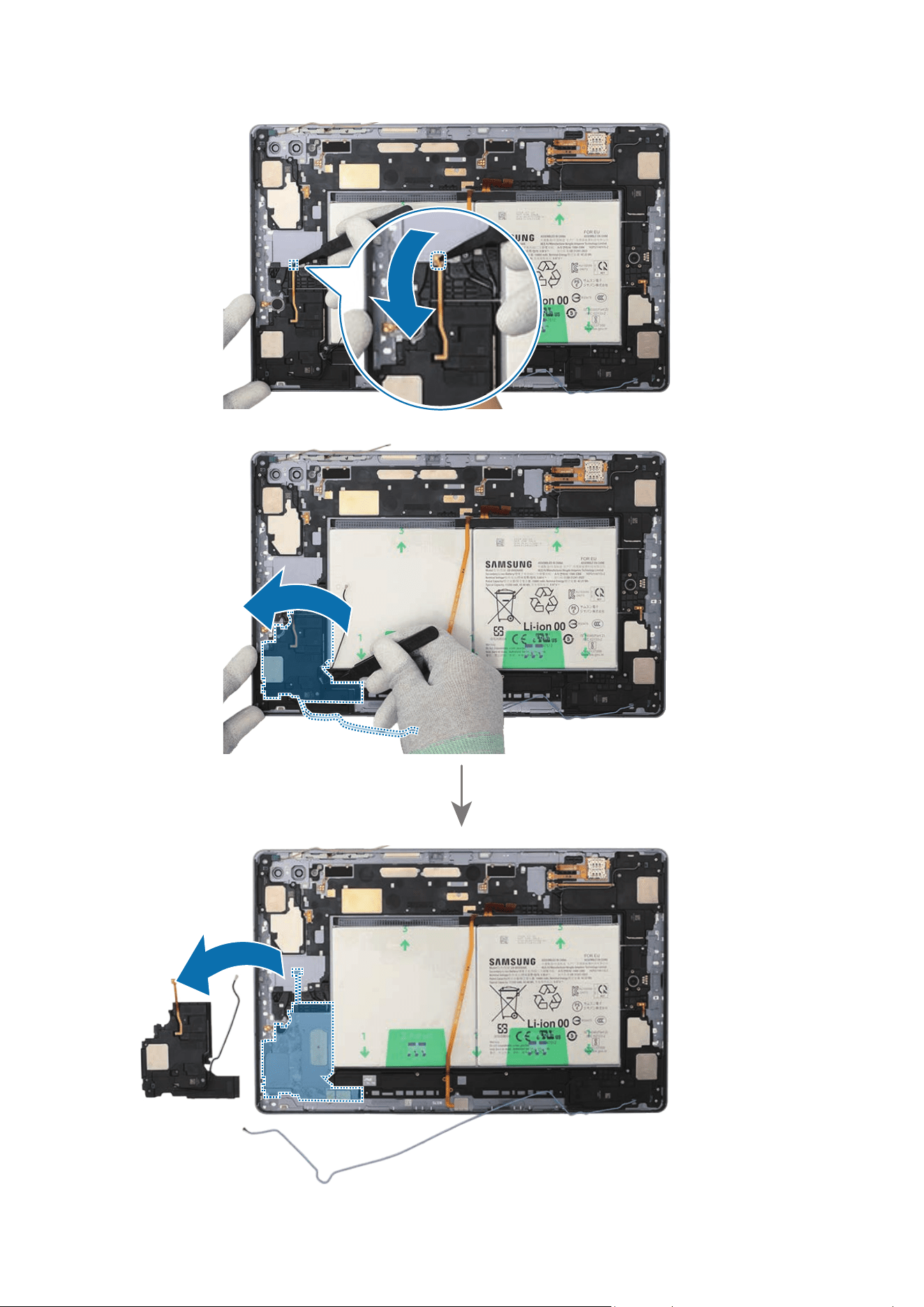
Disassembly and Assembly
253
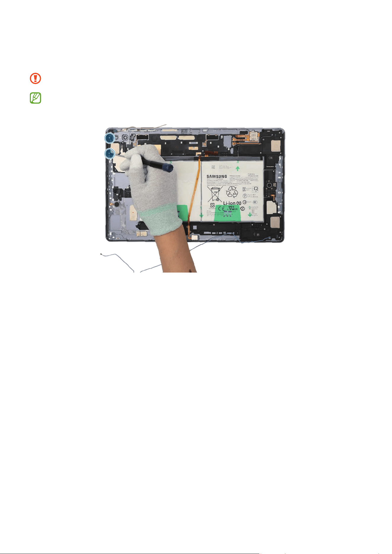
Disassembly and Assembly
254
13
Check the screws at the 2 different points on the speaker 2 and remove them using a
cross-head screwdriver.
Be careful not to damage the near components.
Check the number of screws that have been removed, and store them carefully to
make sure that no unassembled screws are left inside the device during assembly.
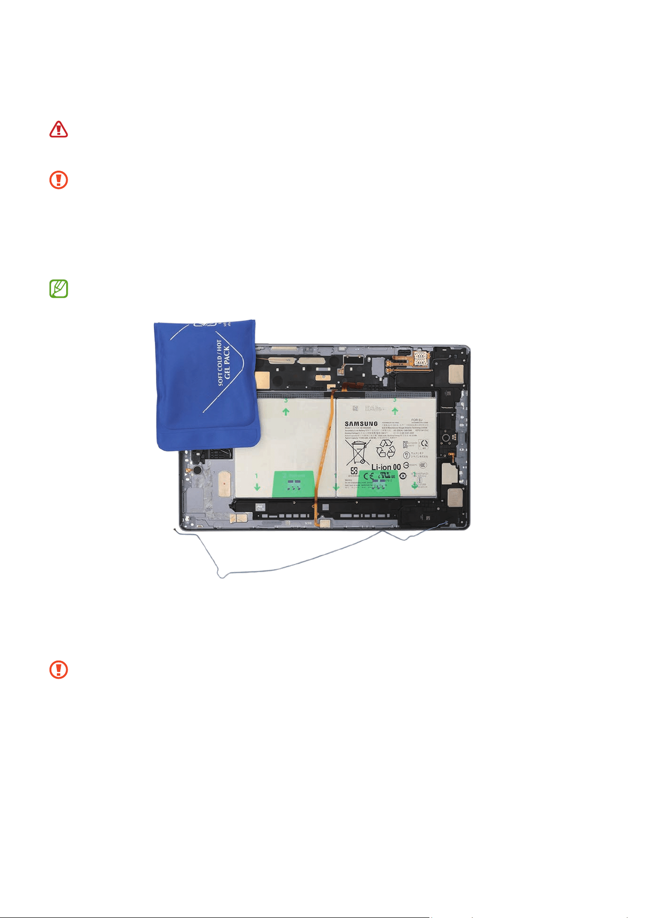
Disassembly and Assembly
255
14
Heat the microwaveable heating bag and apply it to the both front and back side of
the speaker 2 module for 4 minutes.
•
It is possible for the device or battery to be damaged by heat.
•
Do not heat the device in a microwave. Doing so could cause an explosion.
•
Follow the heating bag’s instructions for heating. The recommended time for
heating the bag is 50 seconds in a 1000 W microwave and 70 seconds in a 700 W
microwave. (Correct temperature for use: 55-65 ℃.)
•
Be careful not to damage the device through excessive heat. (It is
recommended to disassemble the device in an area with a temperature gauge.)
When reheating, it should be heated no longer than 30 seconds.
15
Using the tweezers, separate the FPCB of the speaker 2 module carefully. Insert the
tweezers into the separator groove of the speaker 2 and remove it from the back
cover module.
•
Be careful not to damage the speaker and cable.
•
Be careful not to damage the near components.
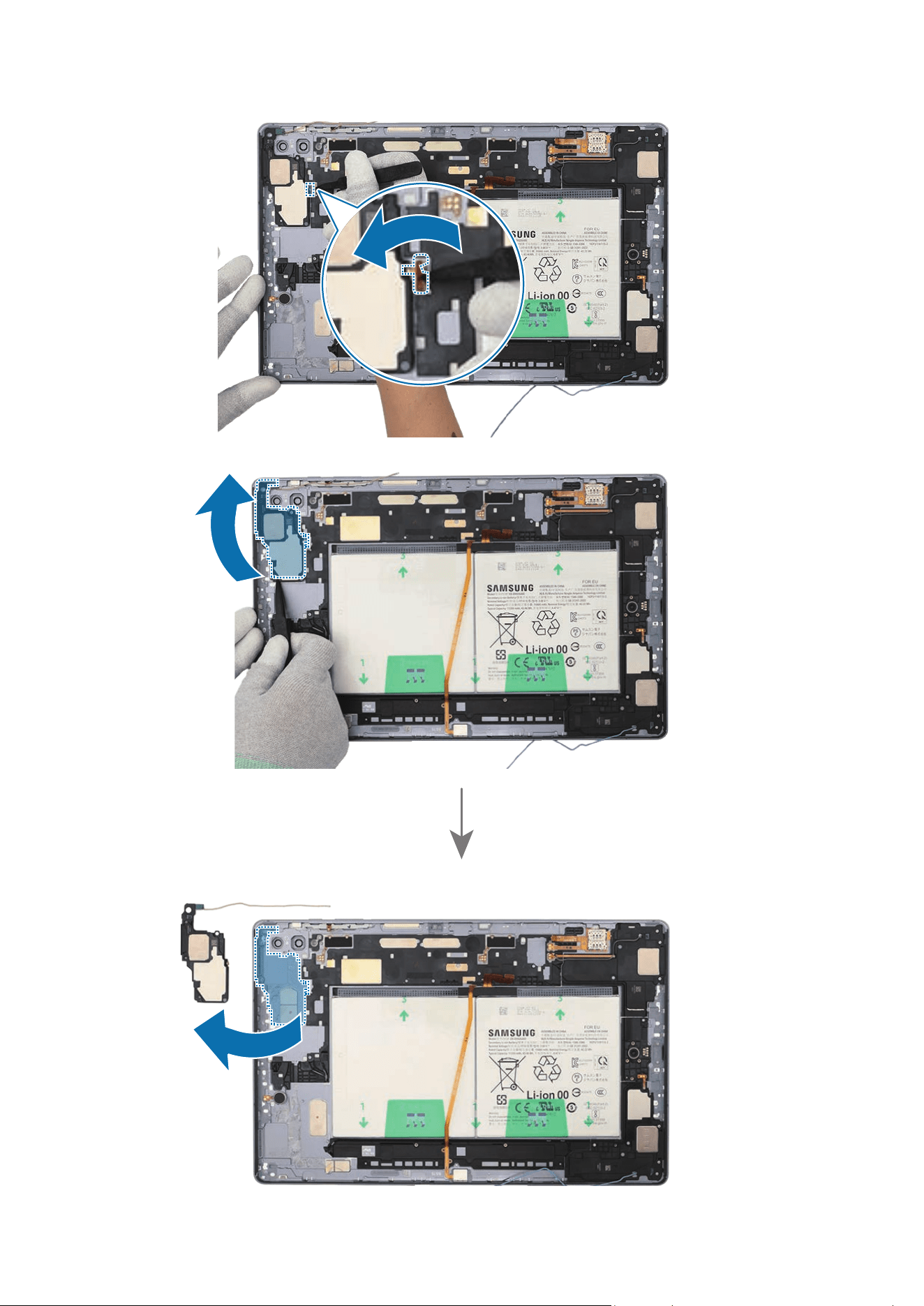
Disassembly and Assembly
256
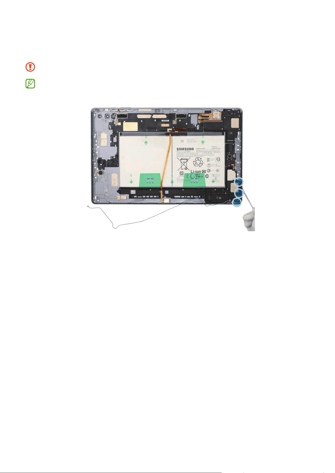
Disassembly and Assembly
257
16
Check the screws at the 3 different points on the speaker 4 and remove them using a
cross-head screwdriver.
Be careful not to damage the near components.
Check the number of screws that have been removed, and store them carefully to
make sure that no unassembled screws are left inside the device during assembly.
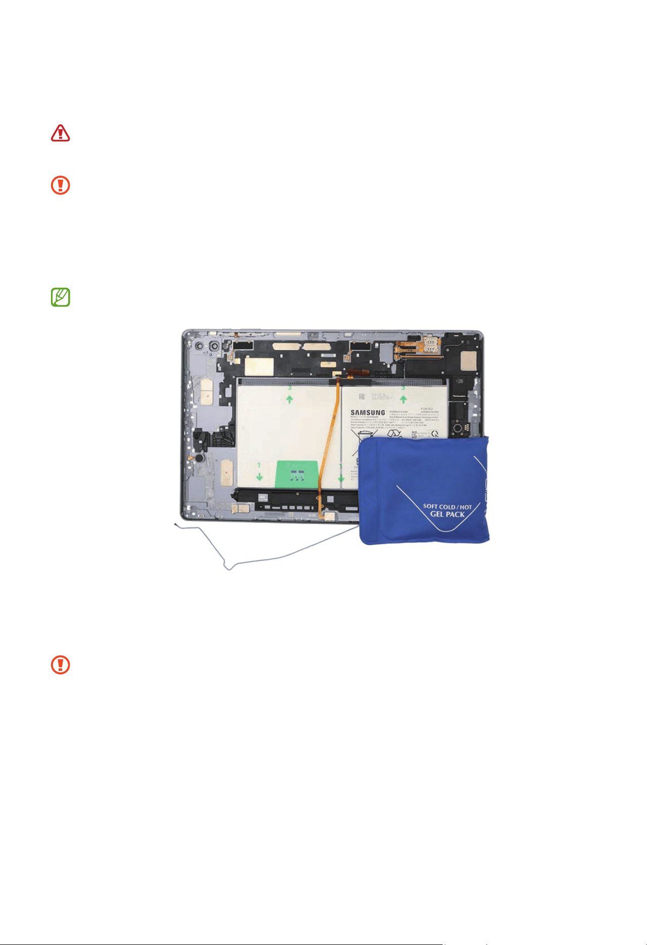
Disassembly and Assembly
258
17
Heat the microwaveable heating bag and apply it to the both front and back side of
the speaker 4 module for 4 minutes.
•
It is possible for the device or battery to be damaged by heat.
•
Do not heat the device in a microwave. Doing so could cause an explosion.
•
Follow the heating bag’s instructions for heating. The recommended time for
heating the bag is 50 seconds in a 1000 W microwave and 70 seconds in a 700 W
microwave. (Correct temperature for use: 55-65 ℃.)
•
Be careful not to damage the device through excessive heat. (It is
recommended to disassemble the device in an area with a temperature gauge.)
When reheating, it should be heated no longer than 30 seconds.
18
Using the tweezers, separate the FPCB of the speaker 4 module carefully. Insert the
tweezers into the separator groove of the speaker 4 and remove it from the back
cover module.
•
Be careful not to damage the speaker and cable.
•
Be careful not to damage the near components.
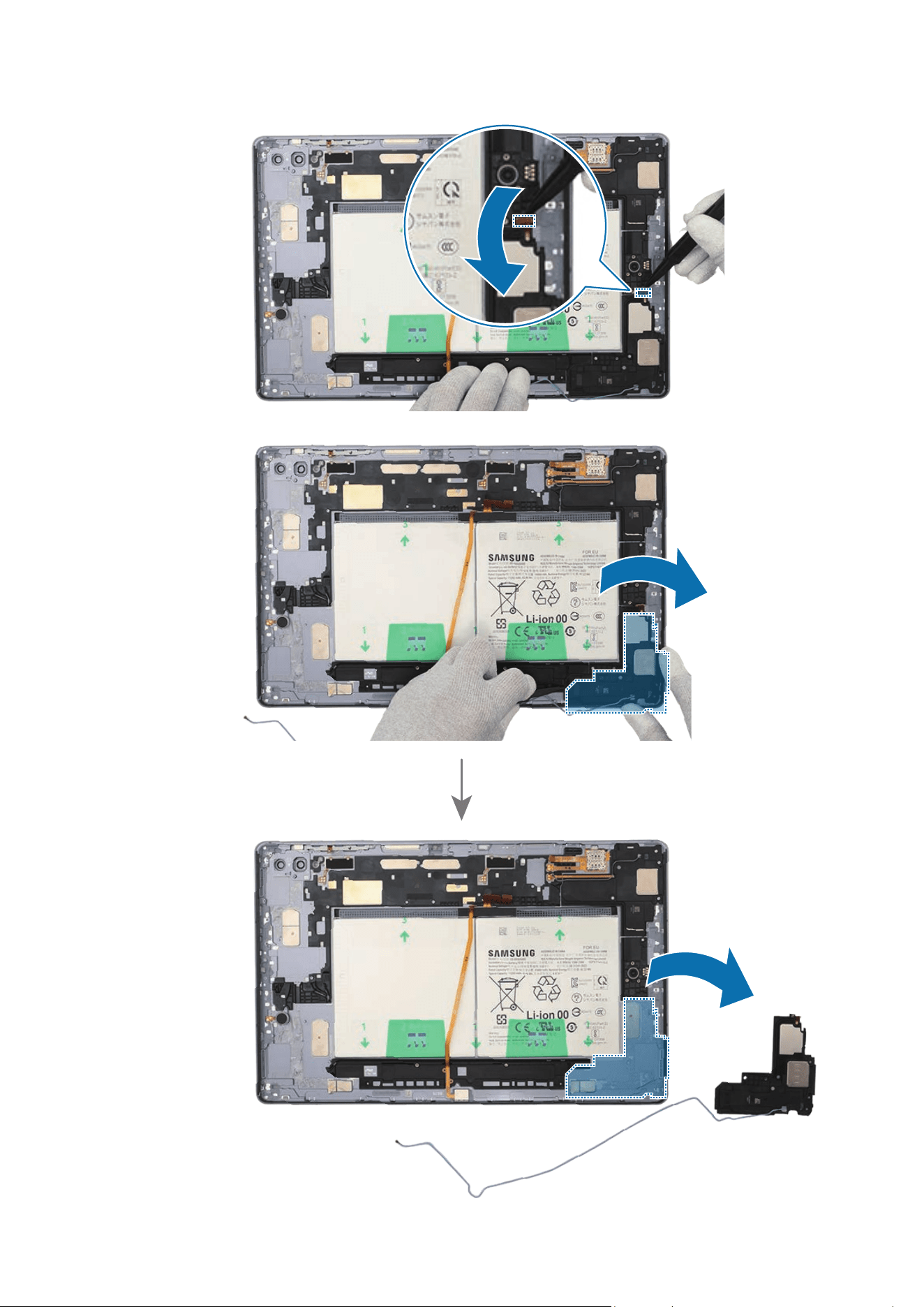
Disassembly and Assembly
259
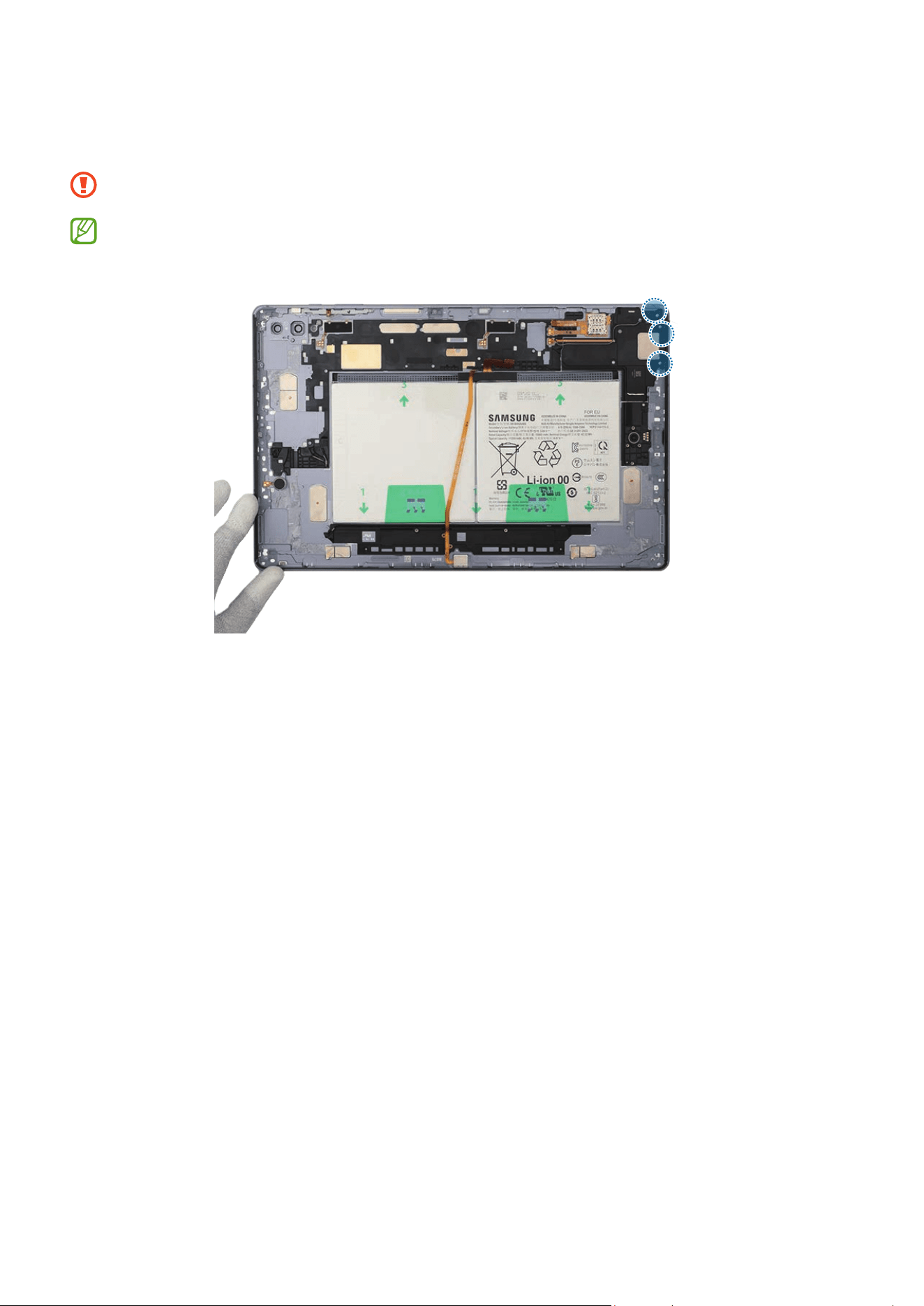
Disassembly and Assembly
260
19
Check the screws at the 3 different points on the speaker 3 and remove them using a
cross-head screwdriver.
Be careful not to damage the near components.
Check the number of screws that have been removed, and store them carefully to
make sure that no unassembled screws are left inside the device during assembly.
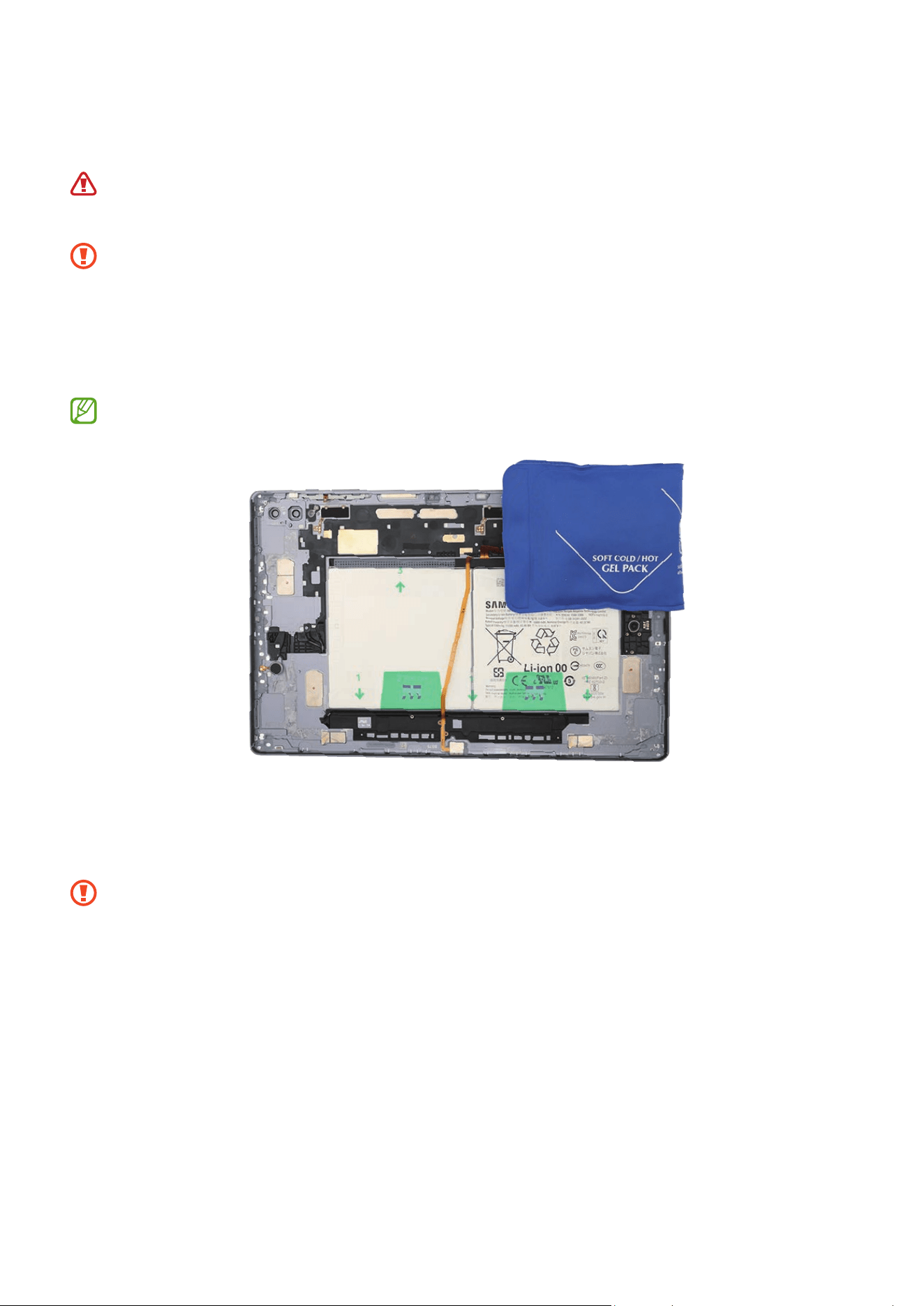
Disassembly and Assembly
261
20
Heat the microwaveable heating bag and apply it to the both front and back side of
the speaker 3 module for 4 minutes.
•
It is possible for the device or battery to be damaged by heat.
•
Do not heat the device in a microwave. Doing so could cause an explosion.
•
Follow the heating bag’s instructions for heating. The recommended time for
heating the bag is 50 seconds in a 1000 W microwave and 70 seconds in a 700 W
microwave. (Correct temperature for use: 55-65 ℃.)
•
Be careful not to damage the device through excessive heat. (It is
recommended to disassemble the device in an area with a temperature gauge.)
When reheating, it should be heated no longer than 30 seconds.
21
Using the tweezers, separate the FPCB of the speaker 3 module carefully. Insert the
tweezers into the separator groove of the speaker 3 and remove it from the back
cover module.
•
Be careful not to damage the speaker and cable.
•
Be careful not to damage the near components.
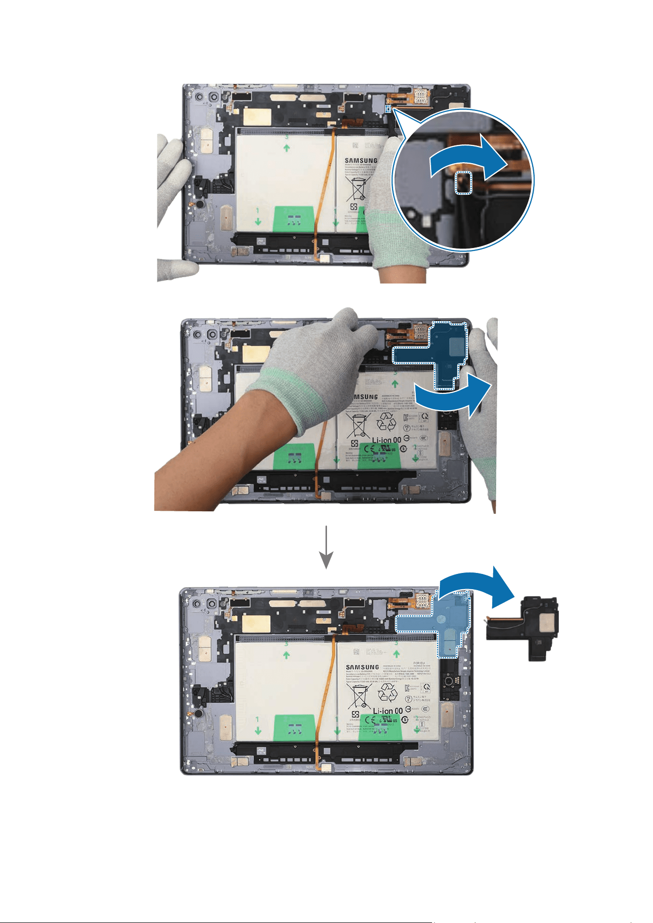
Disassembly and Assembly
262
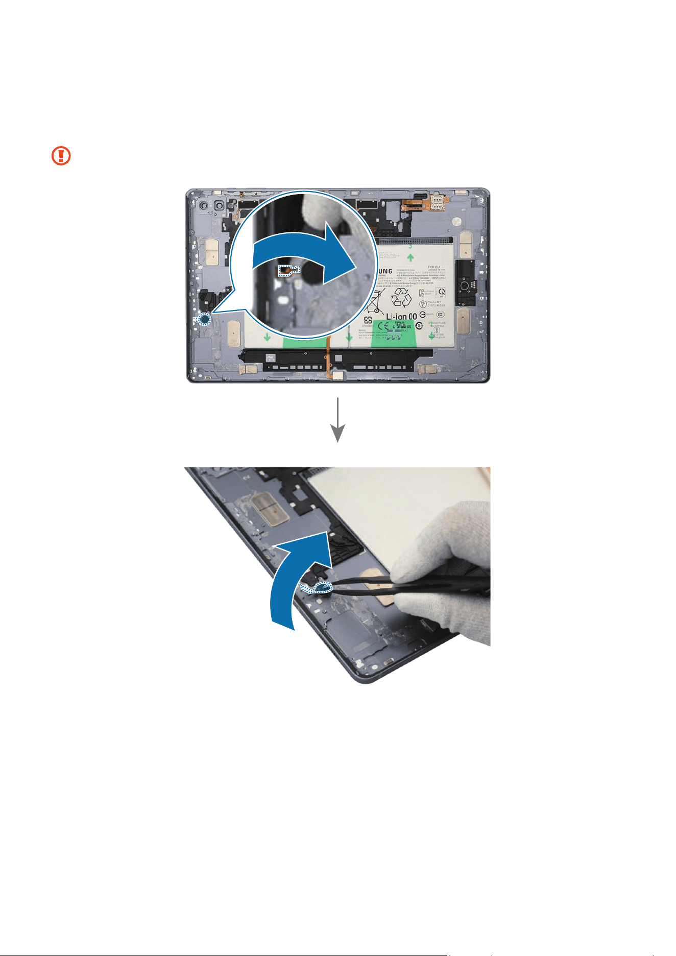
Disassembly and Assembly
263
22
Using the tweezers, separate the FPCB of the vibrator motor carefully from the back
cover module. Then, lift up on the separator groove of the vibrator motor and remove
it carefully from the back cover module.
Be careful not to damage the vibrator motor and the FPCB.
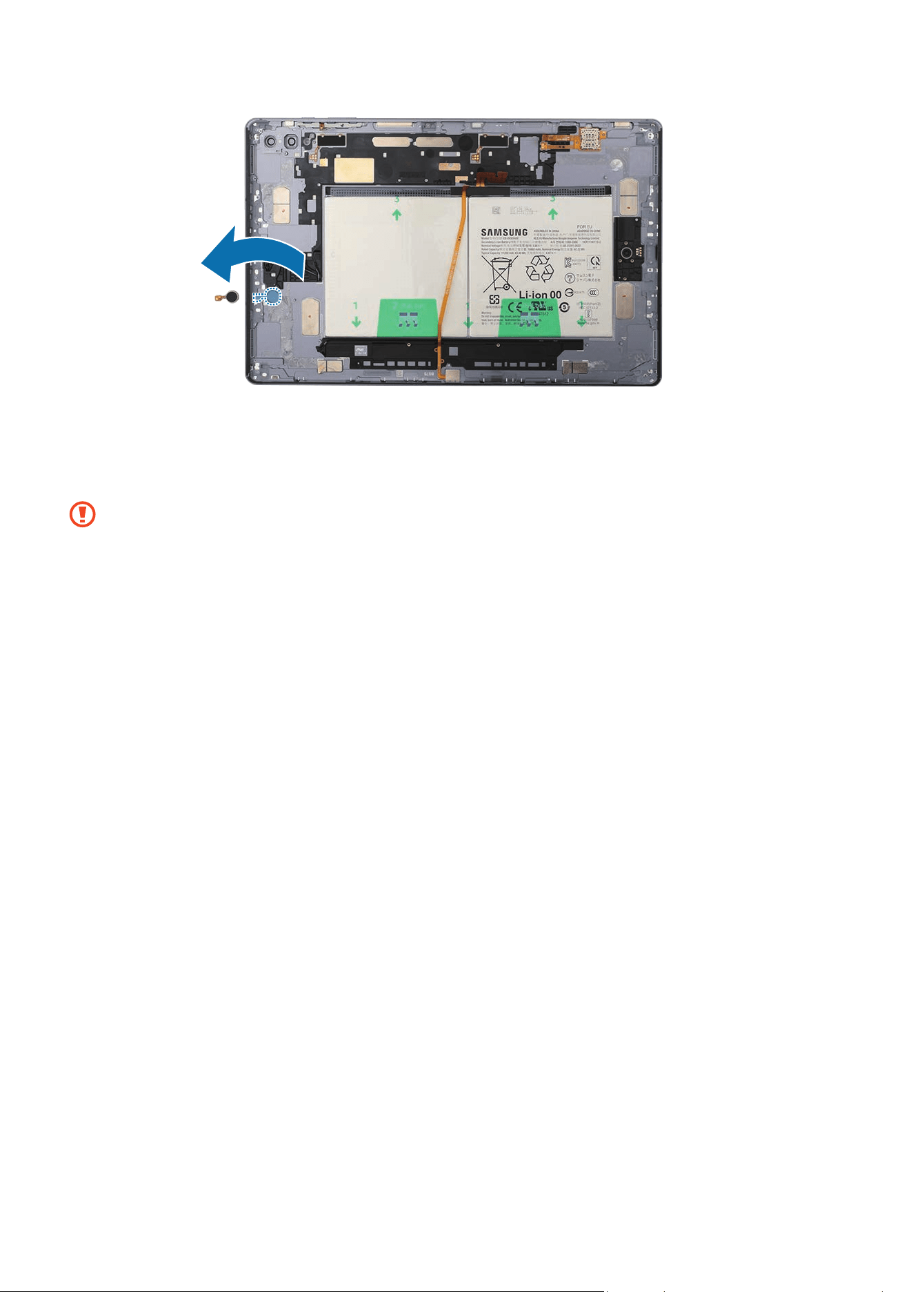
Disassembly and Assembly
264
23
Using the tweezers, separate the FPCB of the SIM card socket carefully from the
back cover module. Then, lift up on the separator groove of the SIM card socket and
remove it carefully from the back cover module.
Be careful not to damage the SIM card socket and the FPCB.
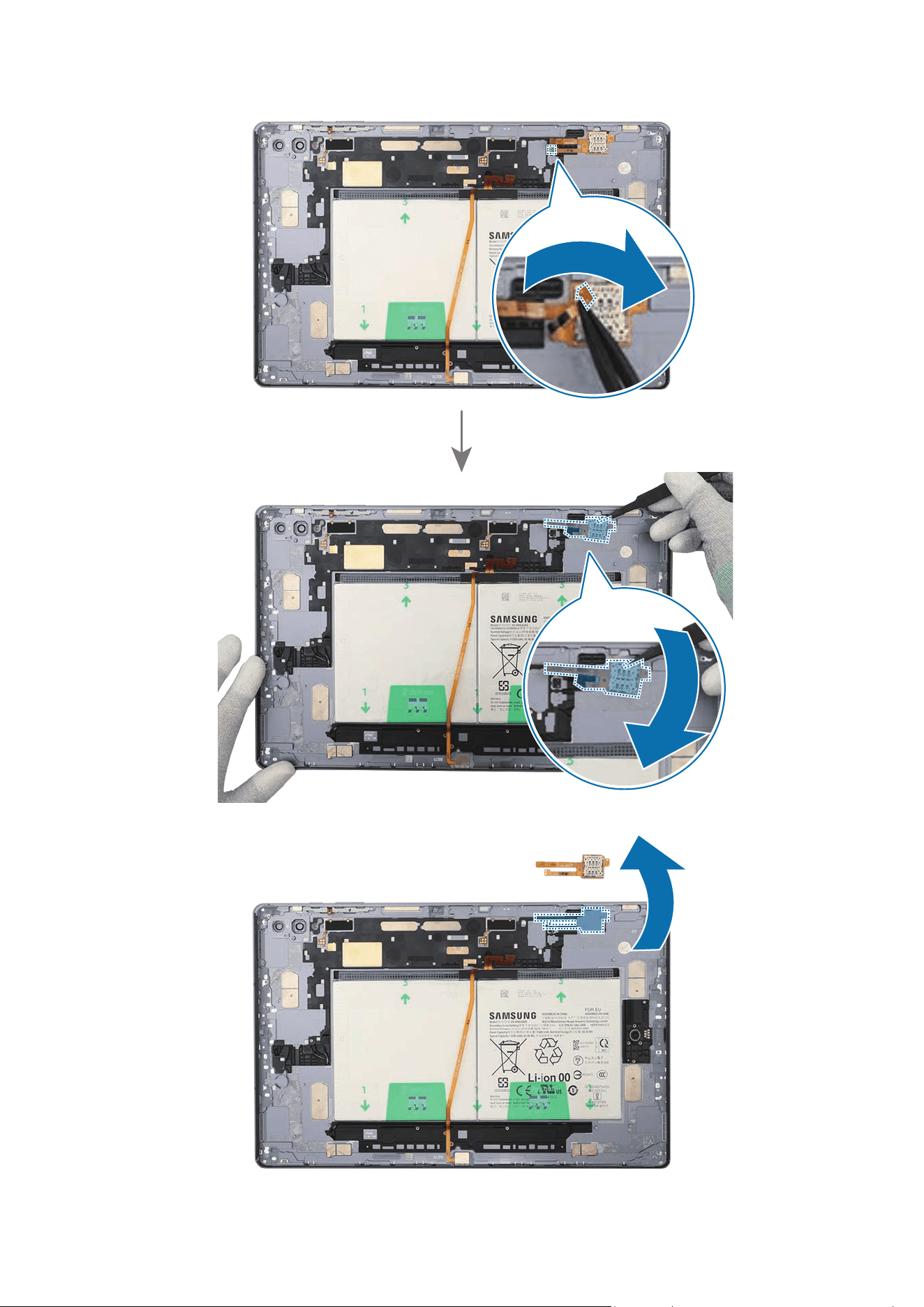
Disassembly and Assembly
265
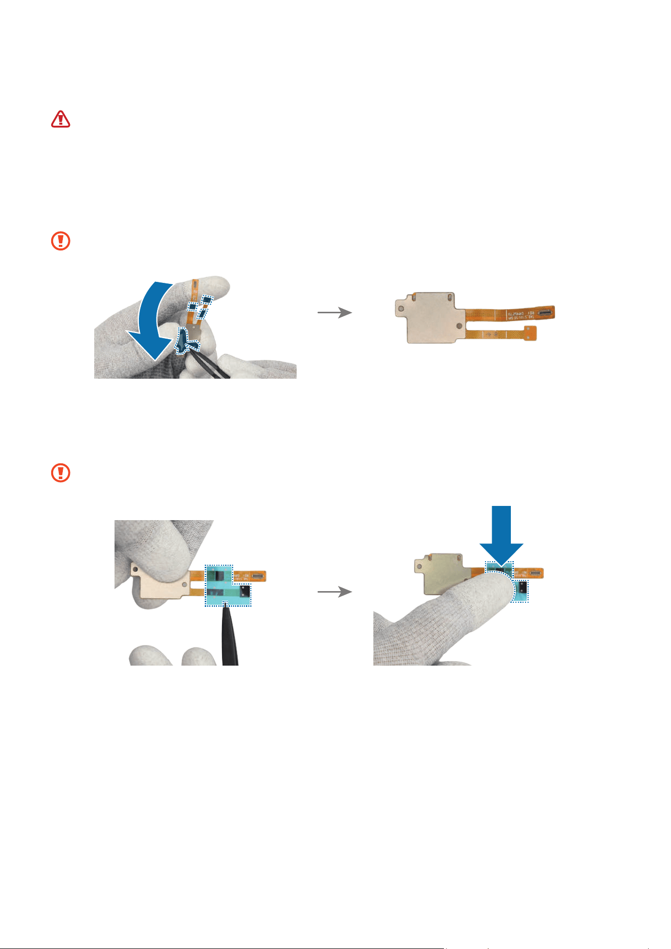
Disassembly and Assembly
266
Reassembly
Leaving screws inside the device may damage internal components, such as the
battery. During assembly, be extra careful not to leave any unassembled screws
inside the device.
1 If you use the existing SIM card socket as it is when reassembling, remove all
adhesive tapes on the bottom of the SIM card socket using the tweezers.
Be careful not to damage the SIM card socket.
2 Using the tweezers, remove the clear film from the new SIM card socket FPCB
adhesive tape and apply it to the bottom of the SIM card socket’s FPCB. Gently press
down on the tape with your fingers so that it can be attached well.
Be careful not to damage the SIM card socket.
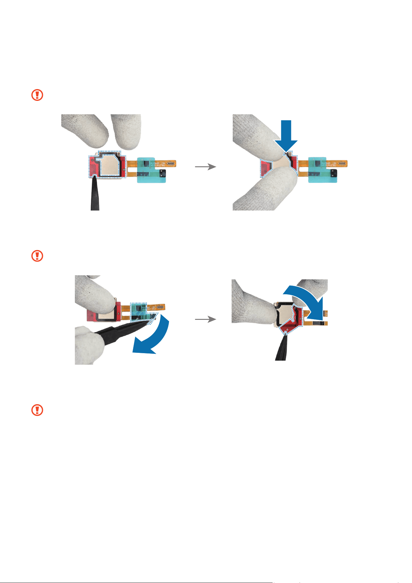
Disassembly and Assembly
267
3 Using the tweezers, remove the clear film from the new SIM card socket adhesive
tape and apply it to the bottom of the SIM card socket. Gently press down on the tape
with your fingers so that it can be attached well.
Be careful not to damage the SIM card socket.
4 Using the tweezers, hold the protruding release films of all the attached tapes and
carefully remove them.
Be careful not to damage the SIM card socket.
5 Using the tweezers, assemble the SIM card socket to the exact position of the back
cover module and press it down lightly with your fingers so that it is fully attached.
Be careful not to damage the SIM card socket and near components.
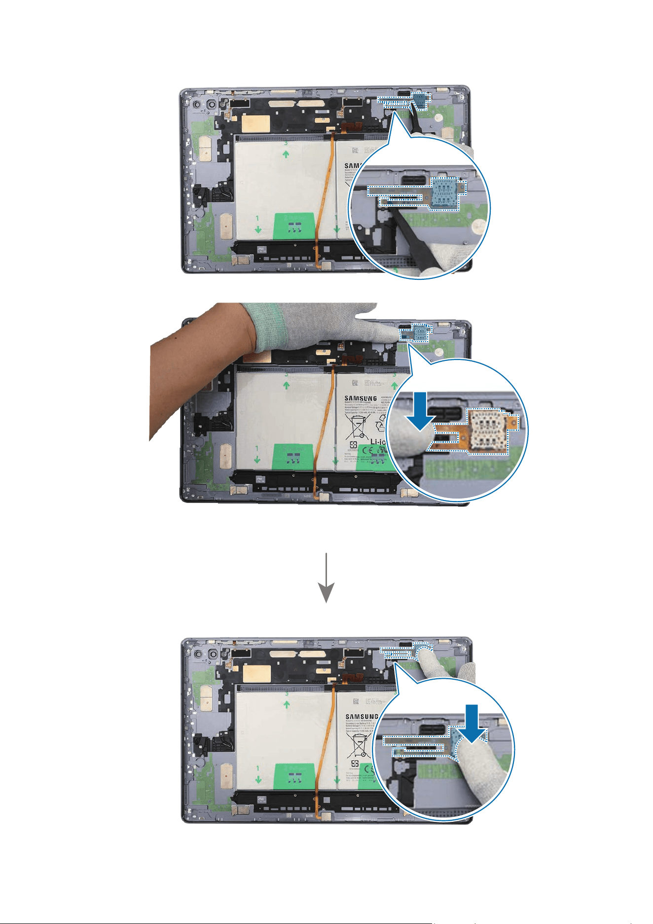
Disassembly and Assembly
268
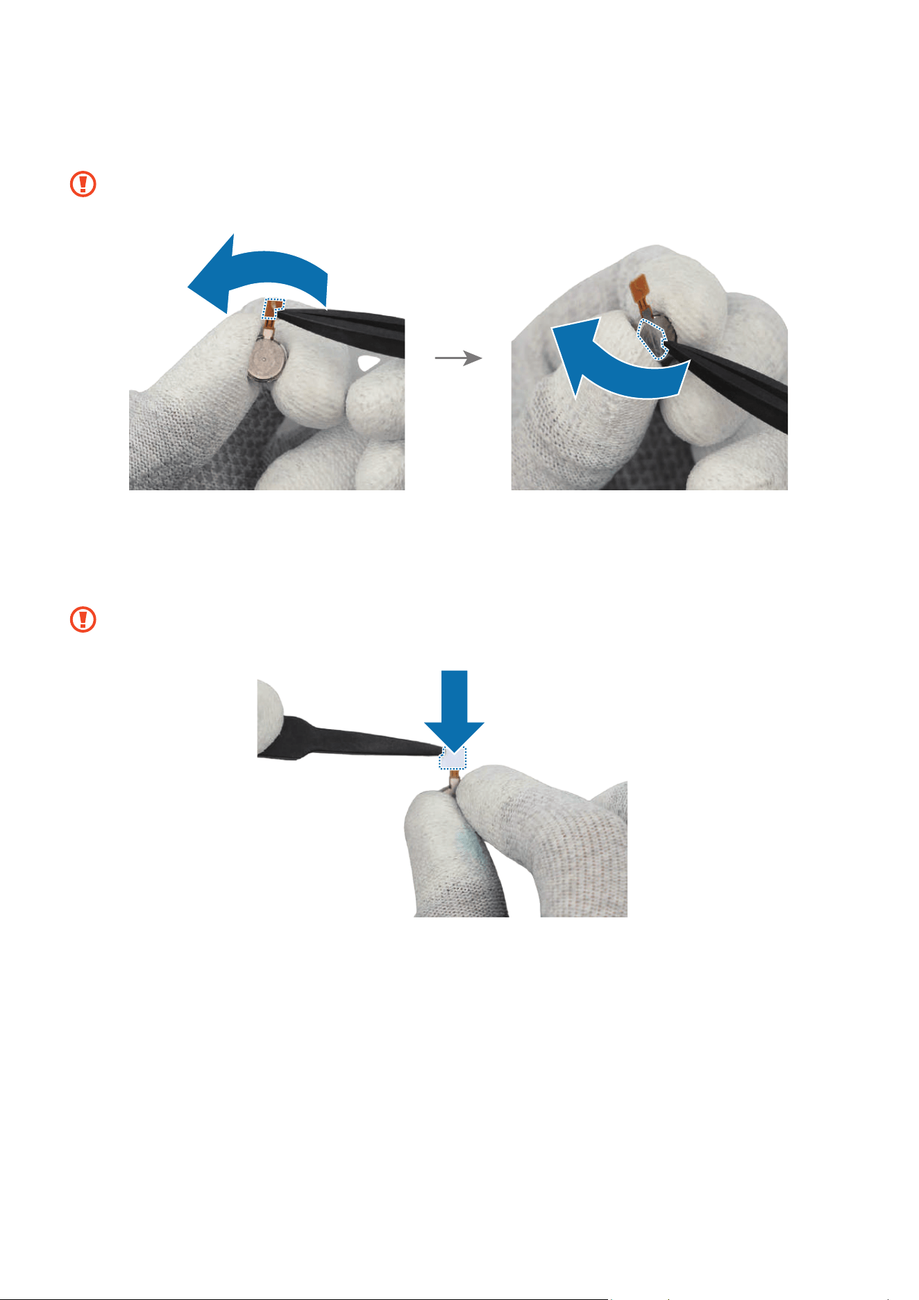
Disassembly and Assembly
269
6 If you use the existing vibrator motor as it is, remove all adhesive tapes on the bottom
of the vibrator motor using the tweezers.
Be careful not to damage the vibrator motor and the FPCB.
7 Using the tweezers, remove the clear film from the new vibrator motor FPCB adhesive
tape and apply it to the bottom of the vibrator motor’s FPCB. Gently press down on
the tape with your fingers so that it can be attached well.
Be careful not to damage the vibrator motor and the FPCB.
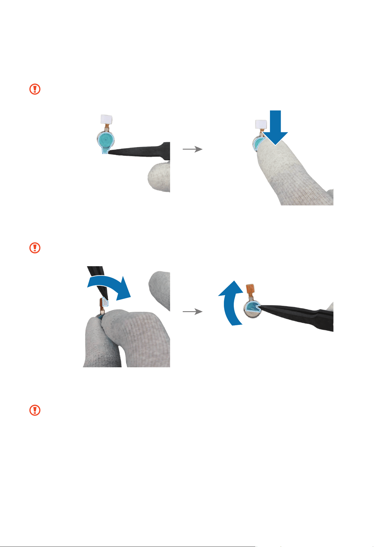
Disassembly and Assembly
270
8 Using the tweezers, remove the clear film from the new vibrator motor adhesive tape
and apply it to the bottom of the vibrator motor. Gently press down on the tape with
your fingers so that it can be attached well.
Be careful not to damage the vibrator motor and the FPCB.
9 Using the tweezers, hold the protruding release films of all the attached tapes and
carefully remove them.
Be careful not to damage the vibrator motor and the FPCB.
10
Using the tweezers, assemble the vibrator motor to the exact position of the back
cover module and press it down lightly with your fingers so that it is fully attached.
Be careful not to damage the vibrator motor and near components.
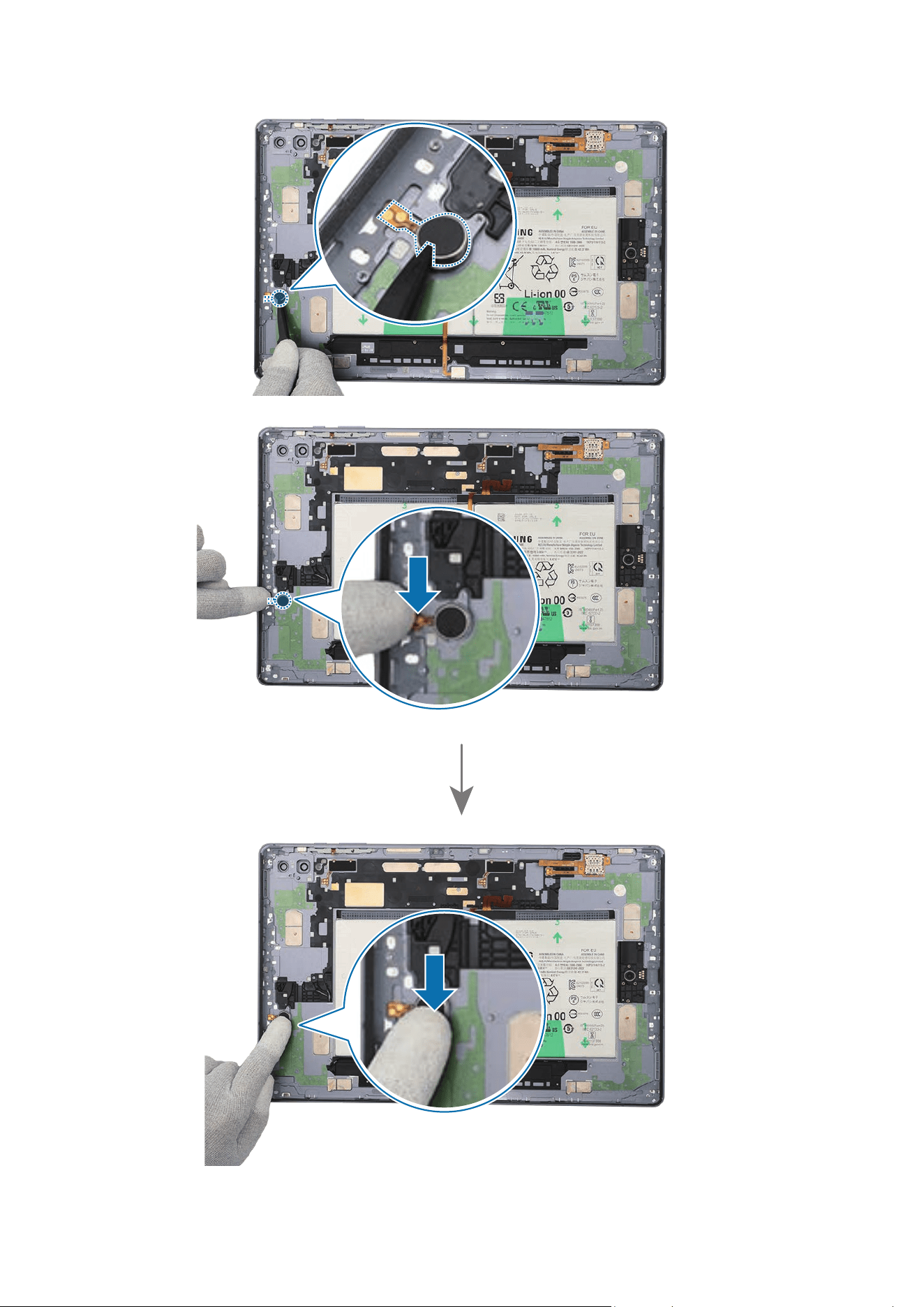
Disassembly and Assembly
271
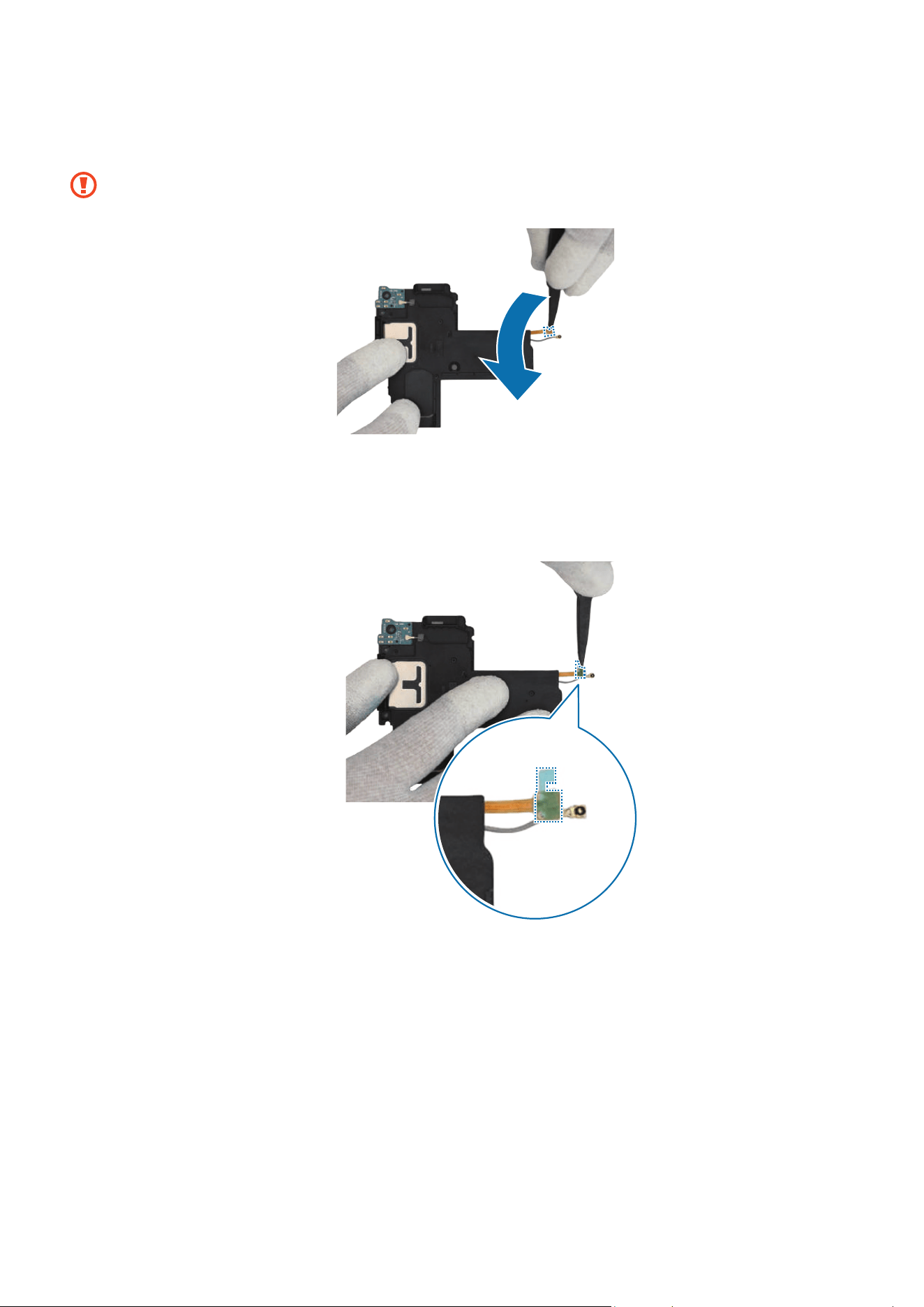
Disassembly and Assembly
272
11
If you use the existing speaker 3 as it is, remove all adhesive tapes on the bottom of
the speaker 3 module’s FPCB using the tweezers.
Be careful not to damage the speaker and the FPCB.
12
Remove the release film from the new FPCB tape and attach it to the FPCB of the
speaker 3 module with the tweezers. Gently press down on the tape with your fingers
so that it can be attached well.
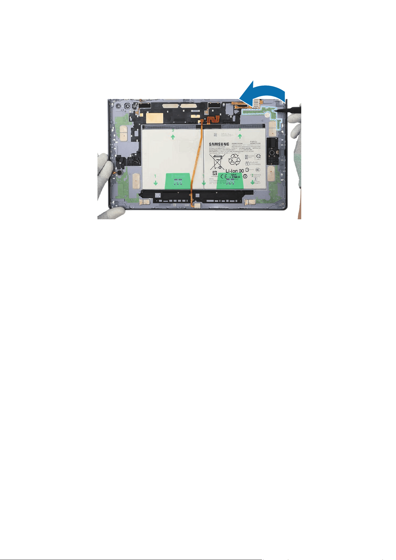
Disassembly and Assembly
273
13
Using the tweezers, remove the release film of the tape attached on the speaker 3
position of the back cover module.
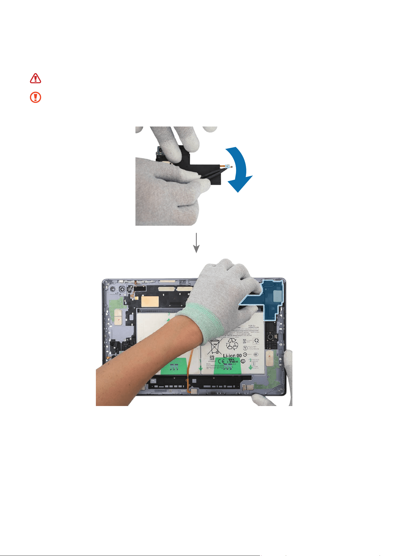
Disassembly and Assembly
274
14
Using the tweezers, remove the release film from the speaker 3 module. Place the
speaker 3 module to the exact position and assemble it to the back cover module.
Be careful not to damage the battery.
•
Be careful not to damage the speaker and cable.
•
Be careful not to damage the near components.
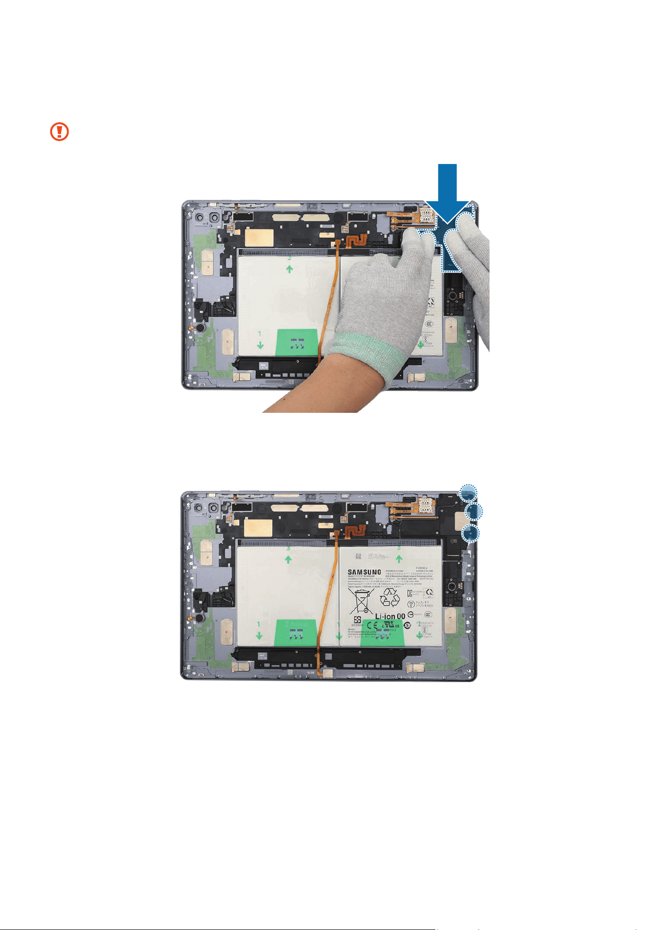
Disassembly and Assembly
275
15
Using your fingers, press down softly and evenly on the speaker 3 module and the
FPCB so that the speaker 3 module can be completely attached.
Be careful not to damage the speaker and cable.
16
Check the screw 3405 (3 ea) and fasten them on the speaker 3 using a cross-head
screwdriver.
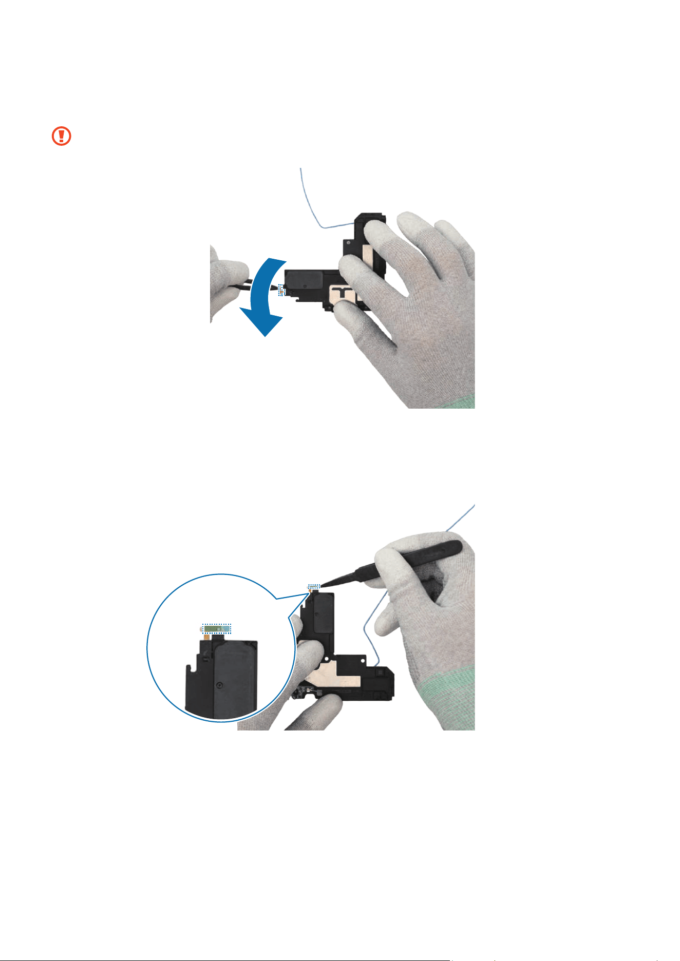
Disassembly and Assembly
276
17
If you use the existing speaker 4 as it is, remove all adhesive tapes on the bottom of
the speaker 4 module’s FPCB using the tweezers.
Be careful not to damage the speaker and the FPCB.
18
Remove the release film from the new FPCB tape and attach it to the FPCB of the
speaker 4 module with the tweezers. Gently press down on the tape with your fingers
so that it can be attached well.
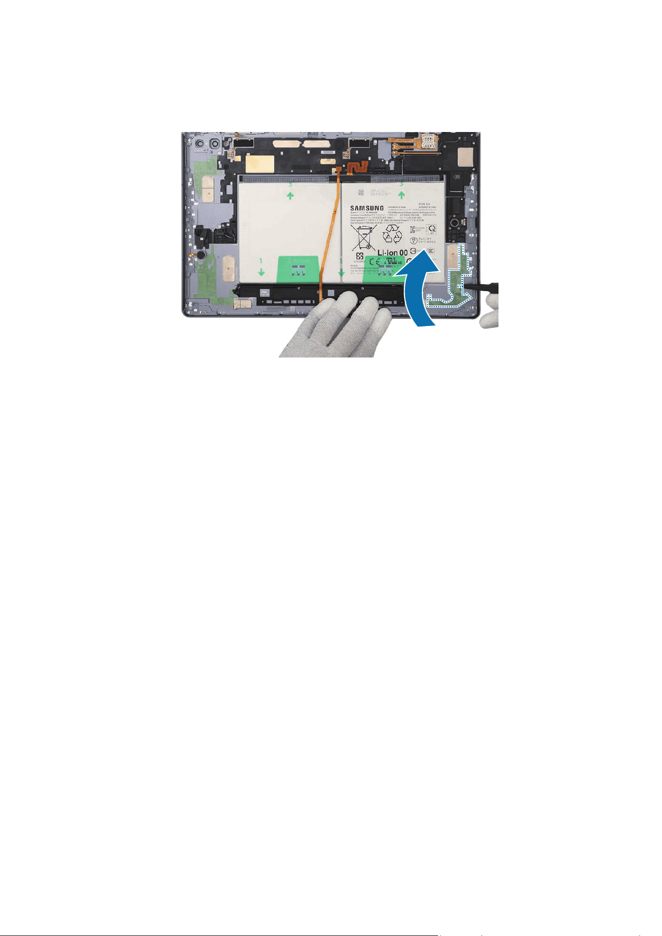
Disassembly and Assembly
277
19
Using the tweezers, remove the release film of the tape attached on the speaker 4
position of the back cover module.
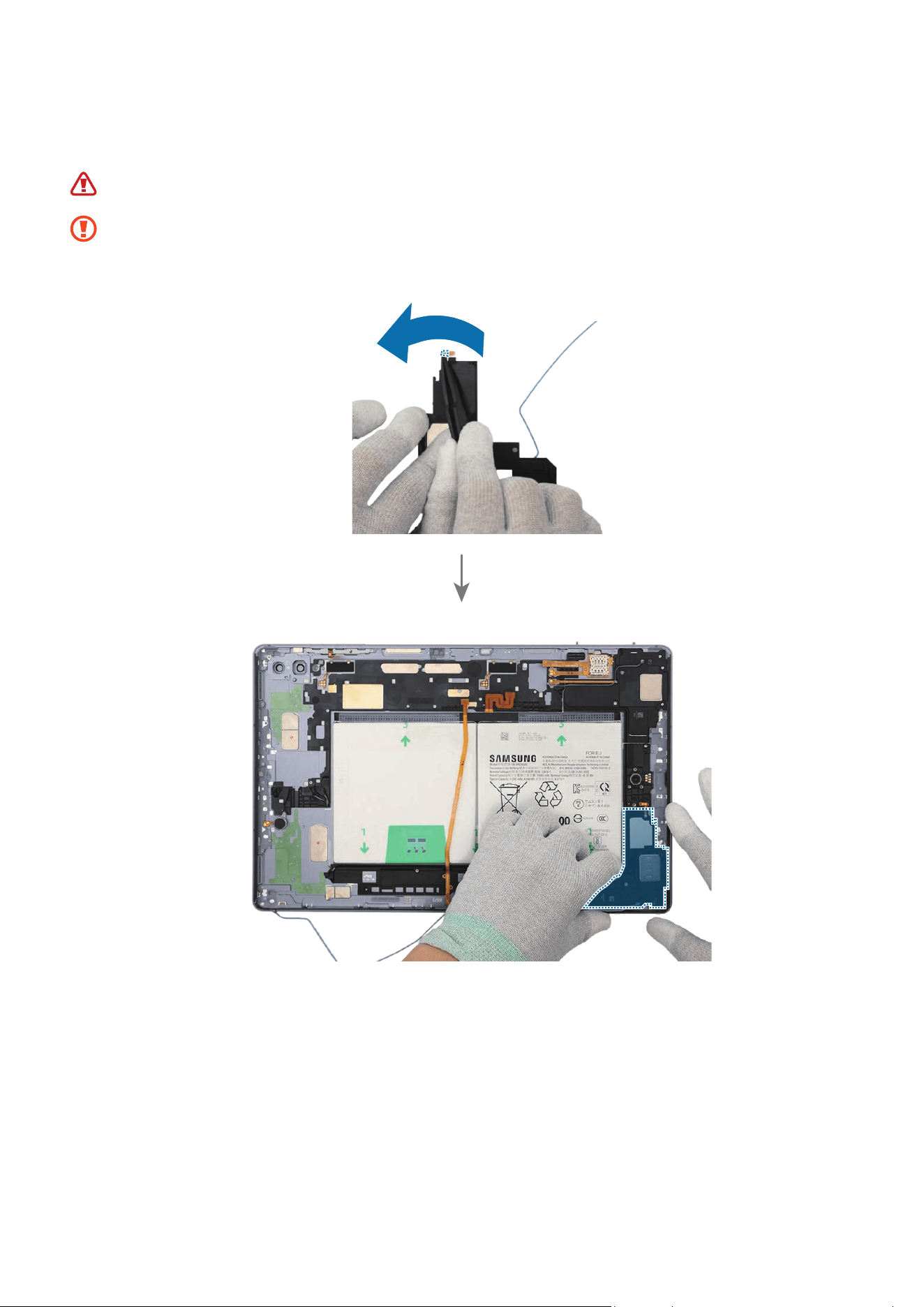
Disassembly and Assembly
278
20
Using the tweezers, remove the release film from the speaker 4 module. Place the
speaker 4 module to the exact position and assemble it to the back cover module.
Be careful not to damage the battery.
•
Be careful not to damage the speaker and cable.
•
Be careful not to damage the near components.
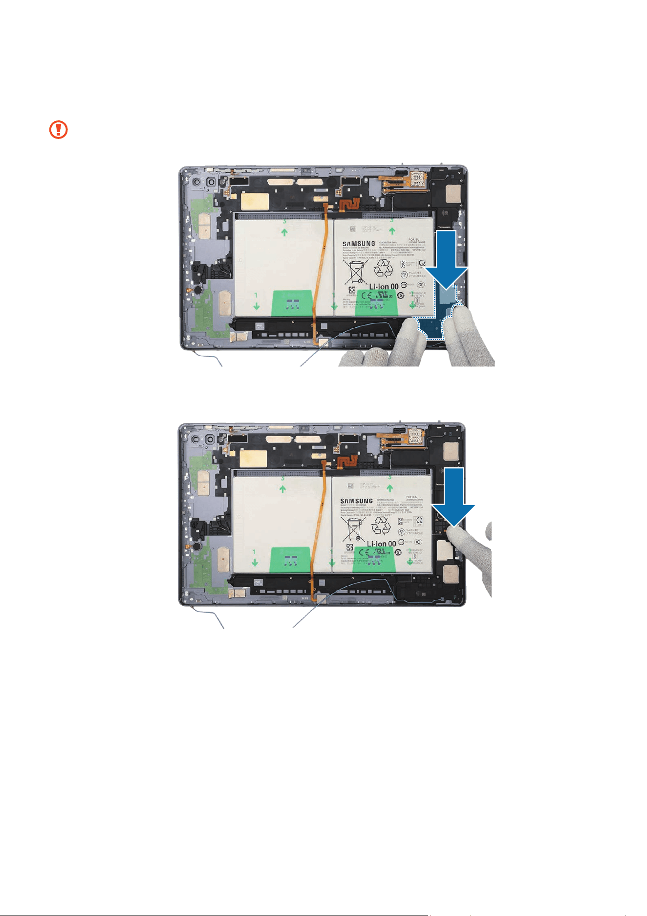
Disassembly and Assembly
279
21
Using your fingers, press down softly and evenly on the speaker 4 module and the
FPCB so that the speaker 4 module can be completely attached.
Be careful not to damage the speaker and cable.
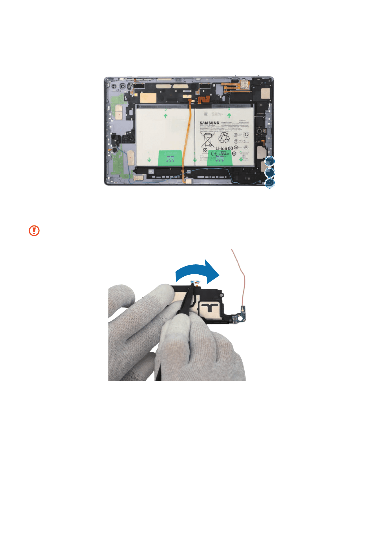
Disassembly and Assembly
280
22
Check the screw 3405 (3 ea) and fasten them on the speaker 4 using a cross-head
screwdriver.
23
If you use the existing speaker 2 as it is, remove all adhesive tapes on the bottom of
the speaker 2 module’s FPCB using the tweezers.
Be careful not to damage the speaker and the FPCB.
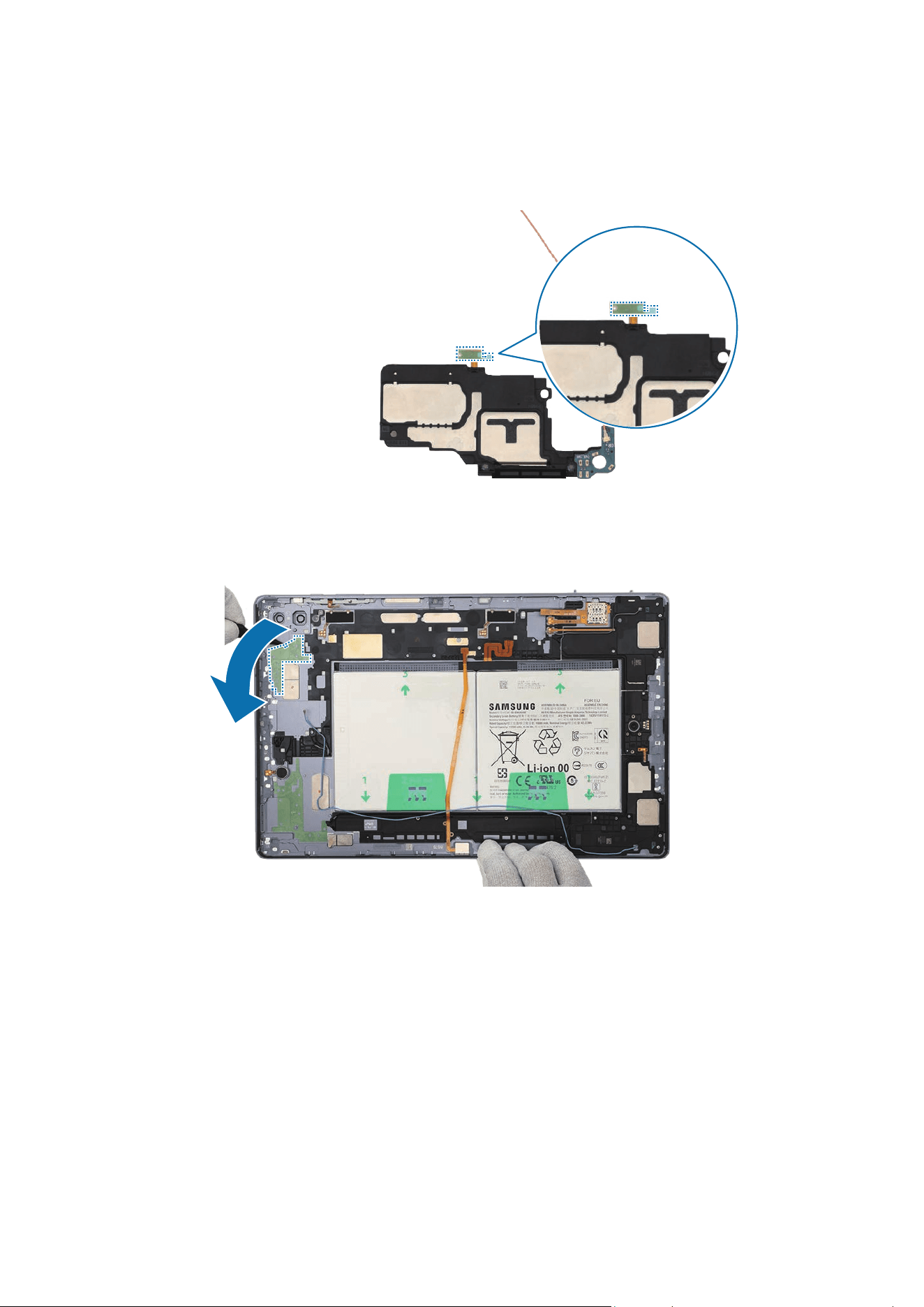
Disassembly and Assembly
281
24
Remove the release film from the new FPCB tape and attach it to the FPCB of the
speaker 2 module with the tweezers. Gently press down on the tape with your fingers
so that it can be attached well.
25
Using the tweezers, remove the release film of the tape attached on the speaker 2
position of the back cover module.
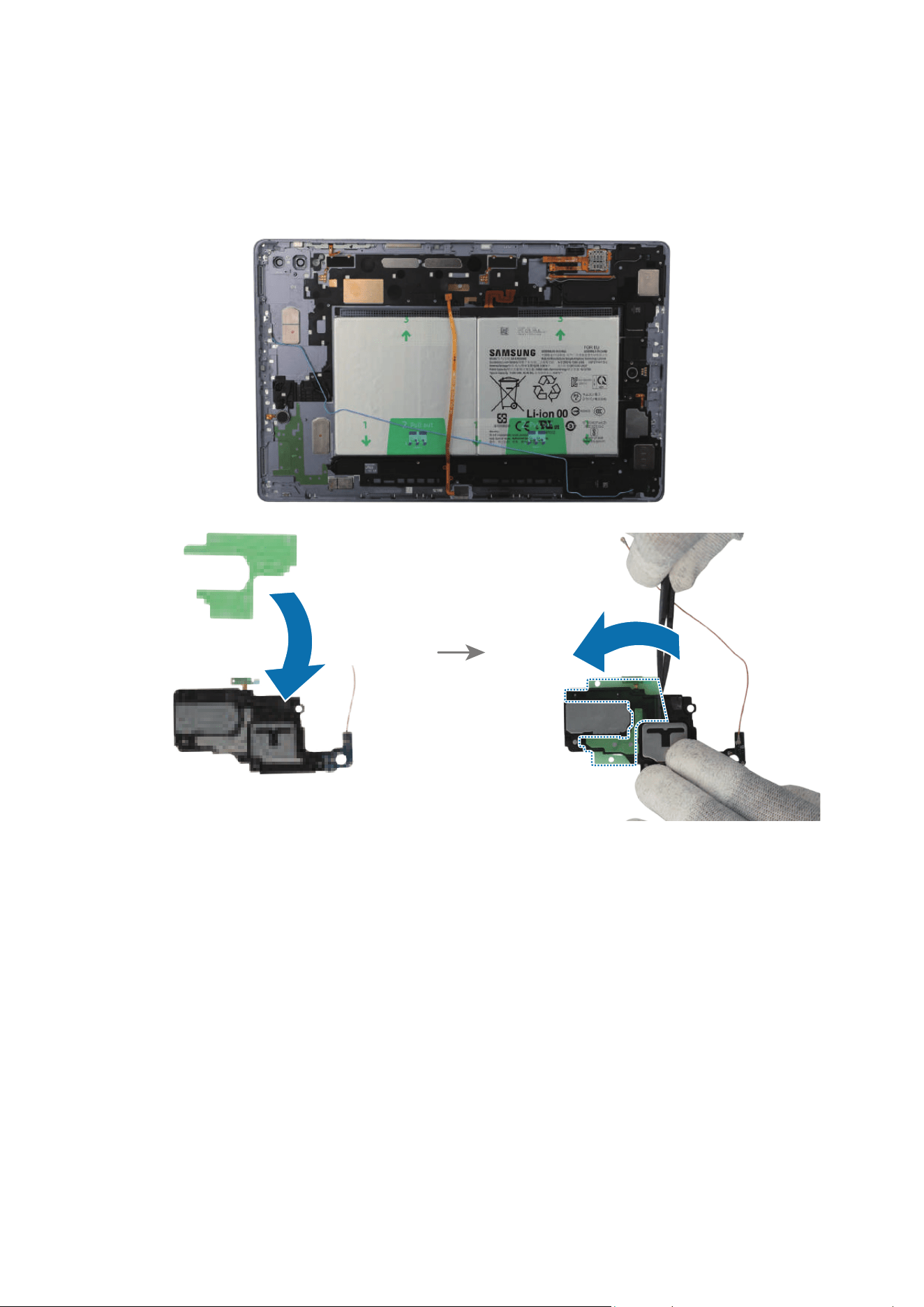
Disassembly and Assembly
282
26
For models without the speaker 2 adhesive tape on the new back cover module,
attach the enclosed speaker 2 adhesive tape to the bottom of the speaker 2. Gently
press down on the tape with your fingers so that it can be attached well, and remove
the release film from the tape.
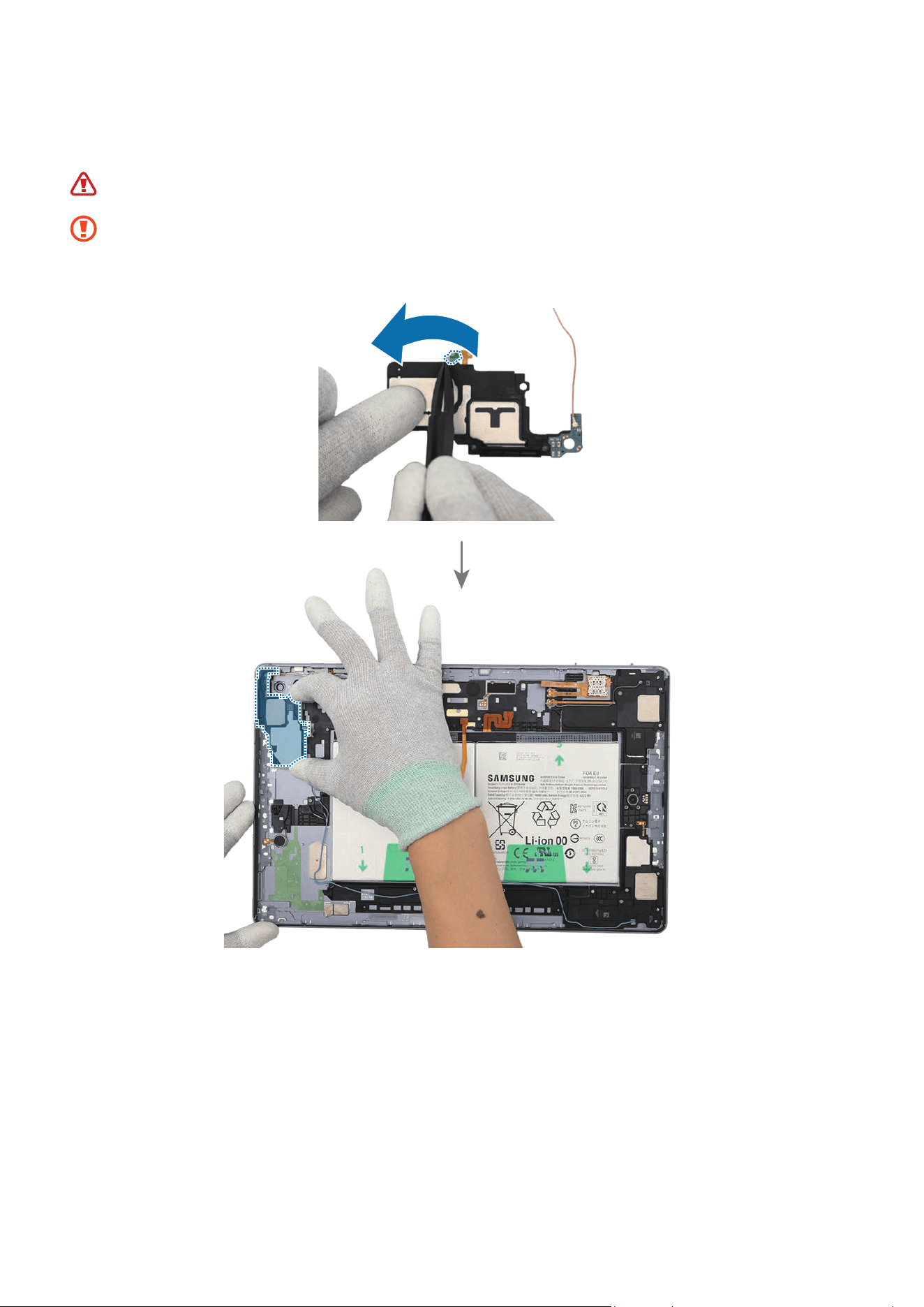
Disassembly and Assembly
283
27
Using the tweezers, remove the release film from the speaker 2 module. Place the
speaker 2 module to the exact position and assemble it to the back cover module.
Be careful not to damage the battery.
•
Be careful not to damage the speaker and cable.
•
Be careful not to damage the near components.
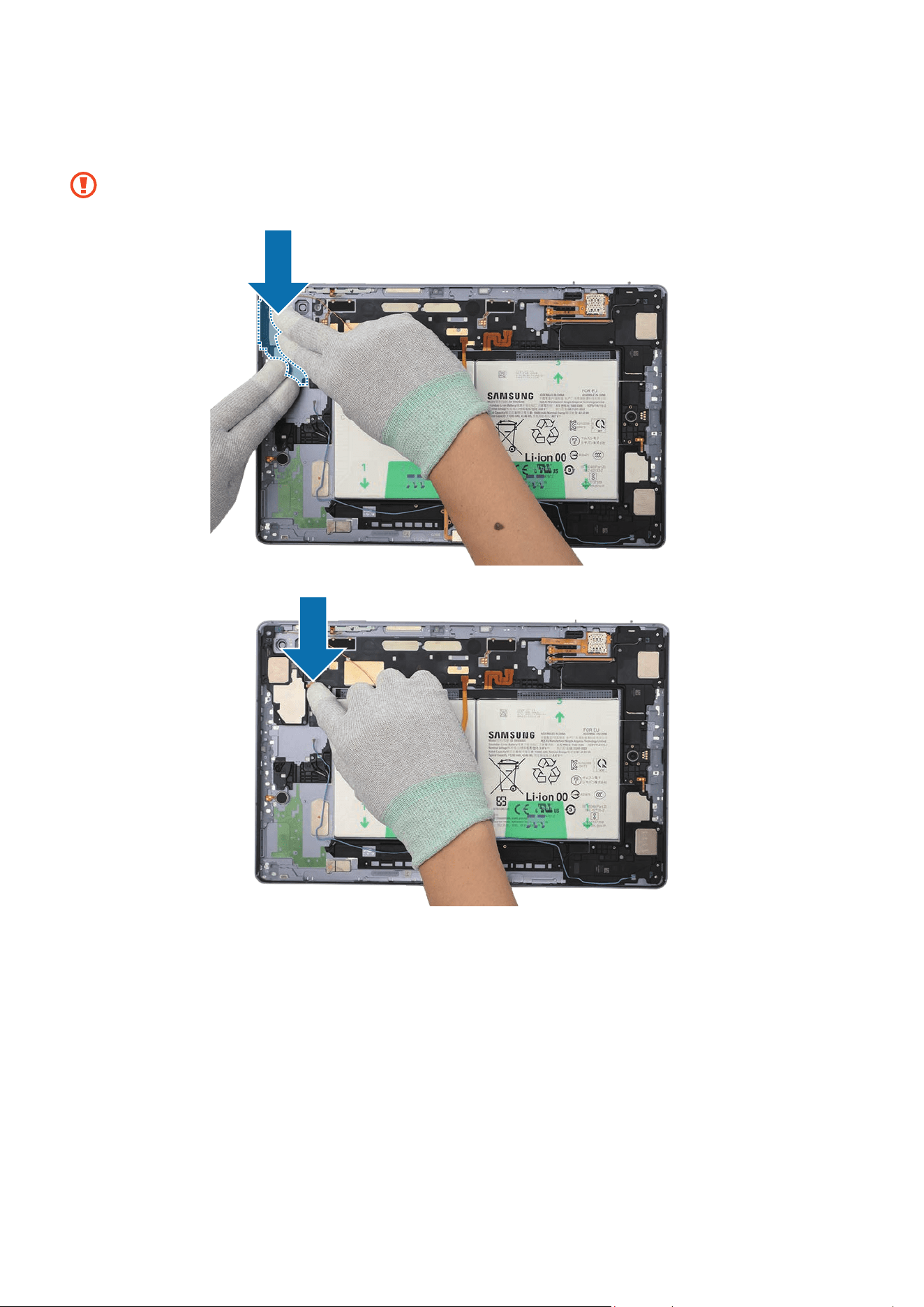
Disassembly and Assembly
284
28
Using your fingers, press down softly and evenly on the speaker 2 module and the
FPCB so that the speaker 2 module can be completely attached.
Be careful not to damage the speaker and cable.
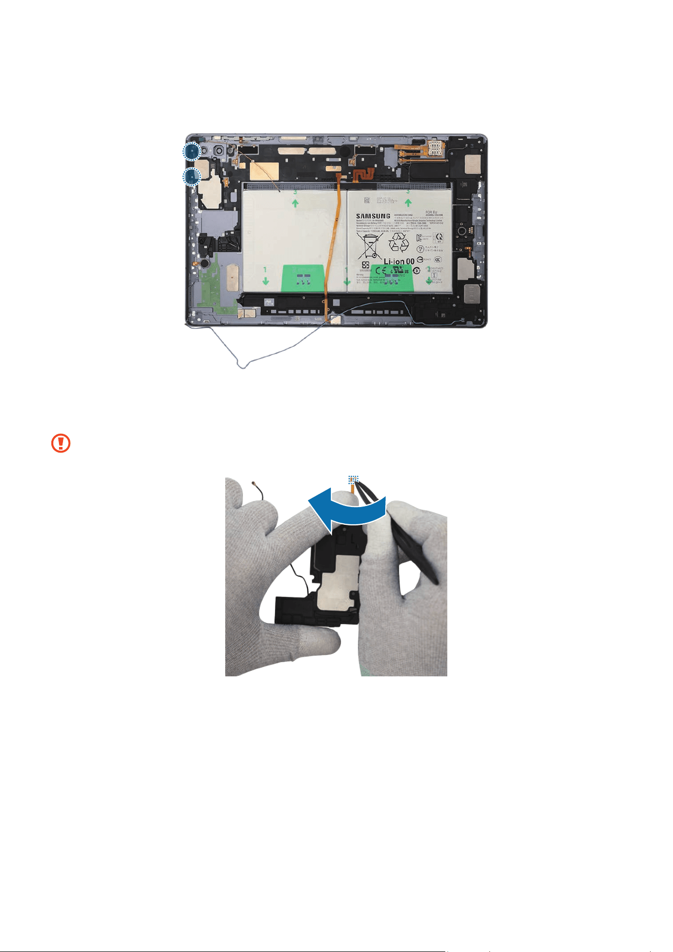
Disassembly and Assembly
285
29
Check the screw 3405 (2 ea) and fasten them on the speaker 2 using a cross-head
screwdriver.
30
If you use the existing speaker 1 as it is, remove all adhesive tapes on the bottom of
the speaker 1 module’s FPCB using the tweezers.
Be careful not to damage the speaker and the FPCB.
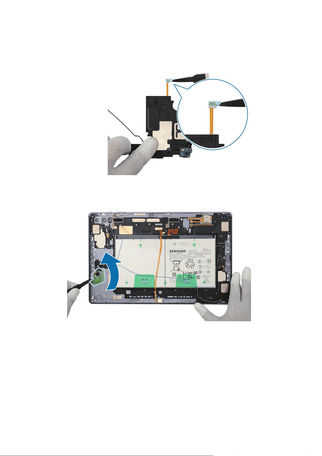
Disassembly and Assembly
286
31
Remove the release film from the new FPCB tape and attach it to the FPCB of the
speaker 1 module with the tweezers. Gently press down on the tape with your fingers
so that it can be attached well.
32
Using the tweezers, remove the release film of the tape attached on the speaker 1
position of the back cover module.
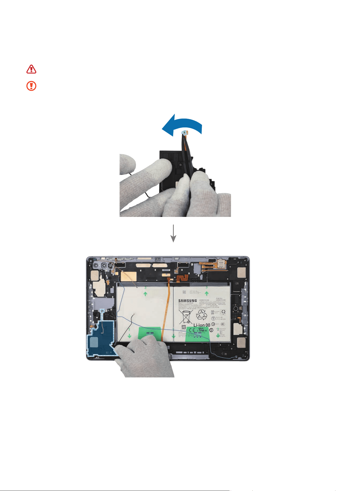
Disassembly and Assembly
287
33
Using the tweezers, remove the release film from the speaker 1 module. Place the
speaker 1 module to the exact position and assemble it to the back cover module.
Be careful not to damage the battery.
•
Be careful not to damage the speaker and cable.
•
Be careful not to damage the near components.
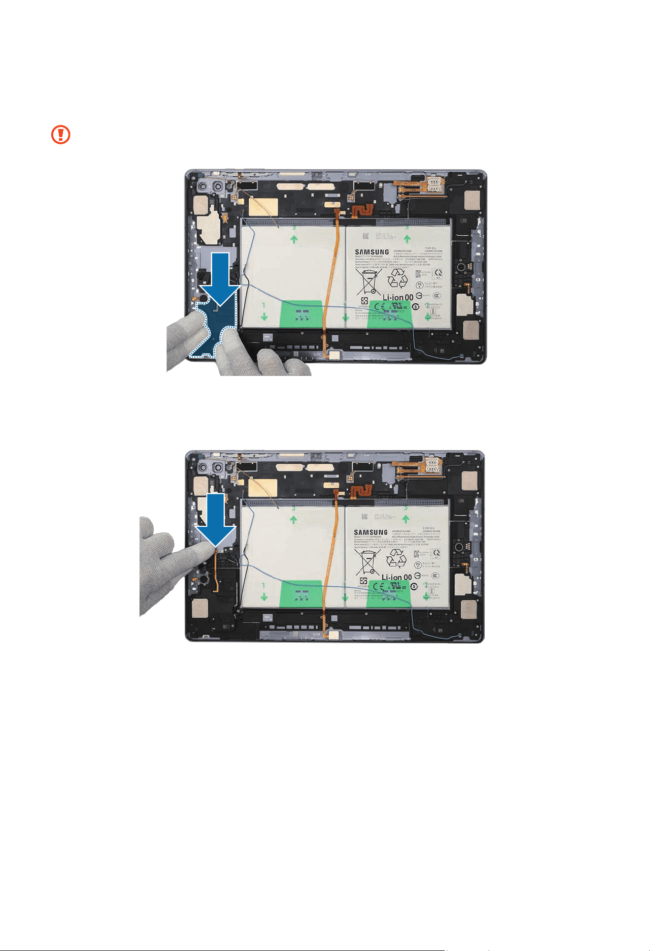
Disassembly and Assembly
288
34
Using your fingers, press down softly and evenly on the speaker 1 module and the
FPCB so that the speaker 1 module can be completely attached.
Be careful not to damage the speaker and cable.
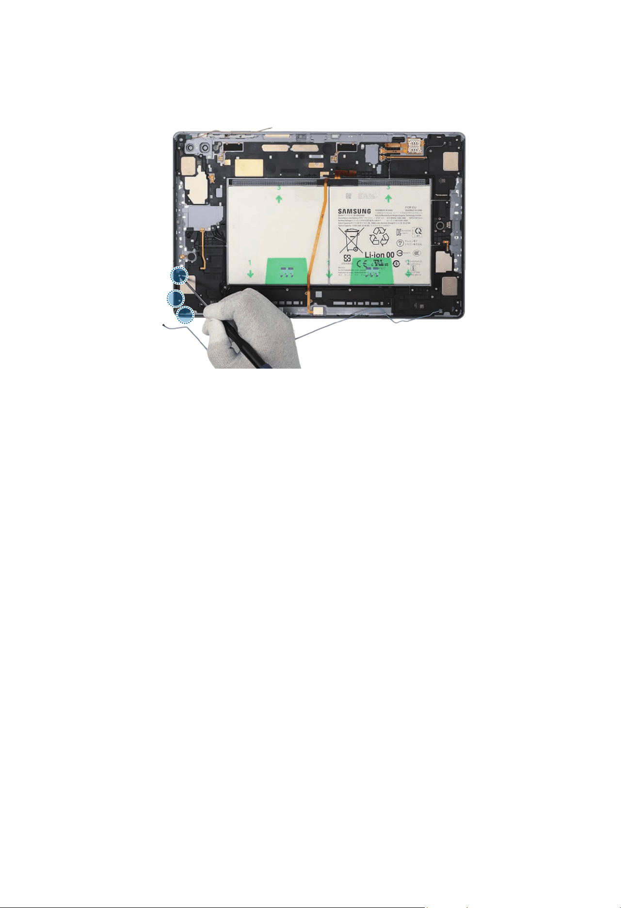
Disassembly and Assembly
289
35
Check the screw 3405 (3 ea) and fasten them on the speaker 1 using a cross-head
screwdriver.
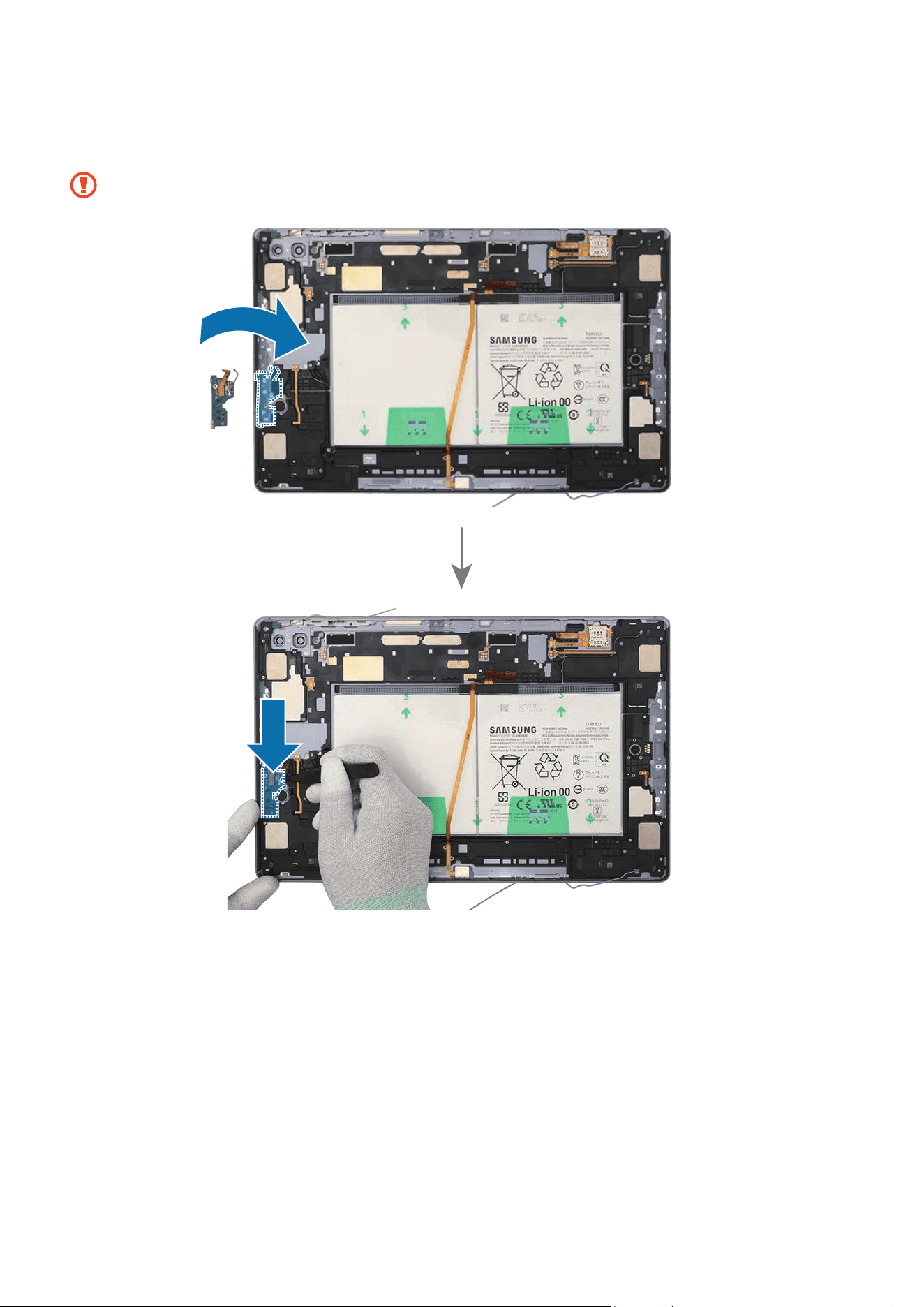
Disassembly and Assembly
290
36
Using the tweezers, assemble the Wi-Fi board to the back cover module and press
down softly and evenly on it so that the Wi-Fi board can be completely attached.
Be careful not to damage the Wi-Fi board and near components.
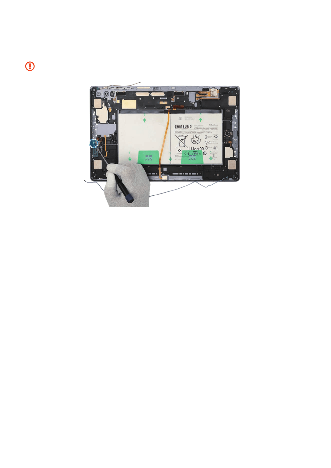
Disassembly and Assembly
291
37
Check the screw 3443 (1 ea) and fasten it on the Wi-Fi board using a cross-head
screwdriver.
Be careful not to damage the Wi-Fi board and near components.
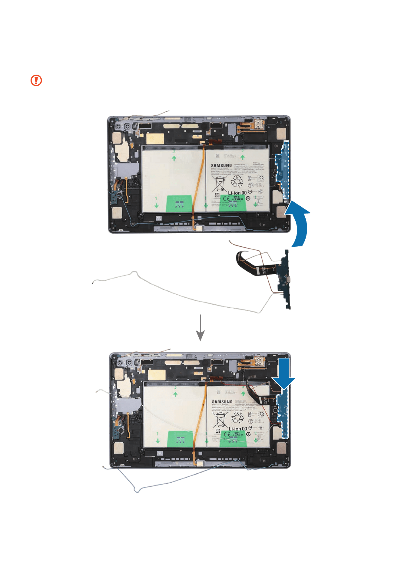
Disassembly and Assembly
292
38
Using the tweezers, insert the charging port to the back cover module and press
down softly and evenly on it so that the charging port can be completely attached.
•
Be careful not to damage the charging port module side contact.
•
Be careful not to damage the near components.
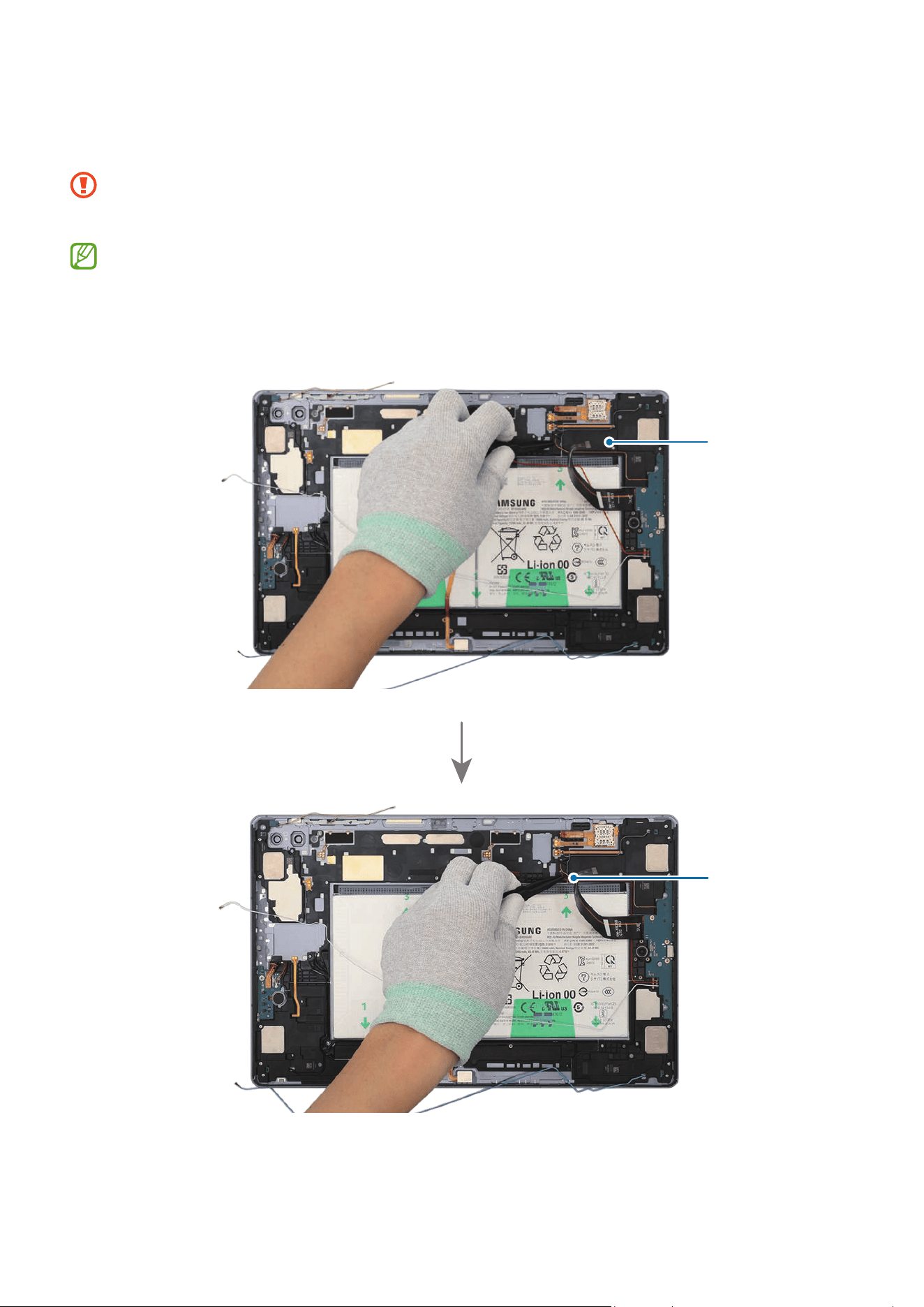
Disassembly and Assembly
293
39
For the 5G or LTE devices, connect the 4 coaxial cables (Orange/Red/White/Blue) to
the speaker modules carefully using the tweezers.
•
Be careful not to damage the charging port and near components.
•
Be careful not to damage the cables.
•
The 4 coaxial cables (Orange/Red/White/Blue) are only available for the 5G or
LTE devices.
•
The cables and connectors may vary depending on the country, region, or
specifications.
Coaxial cable
(Orange)
Coaxial cable
(Red)
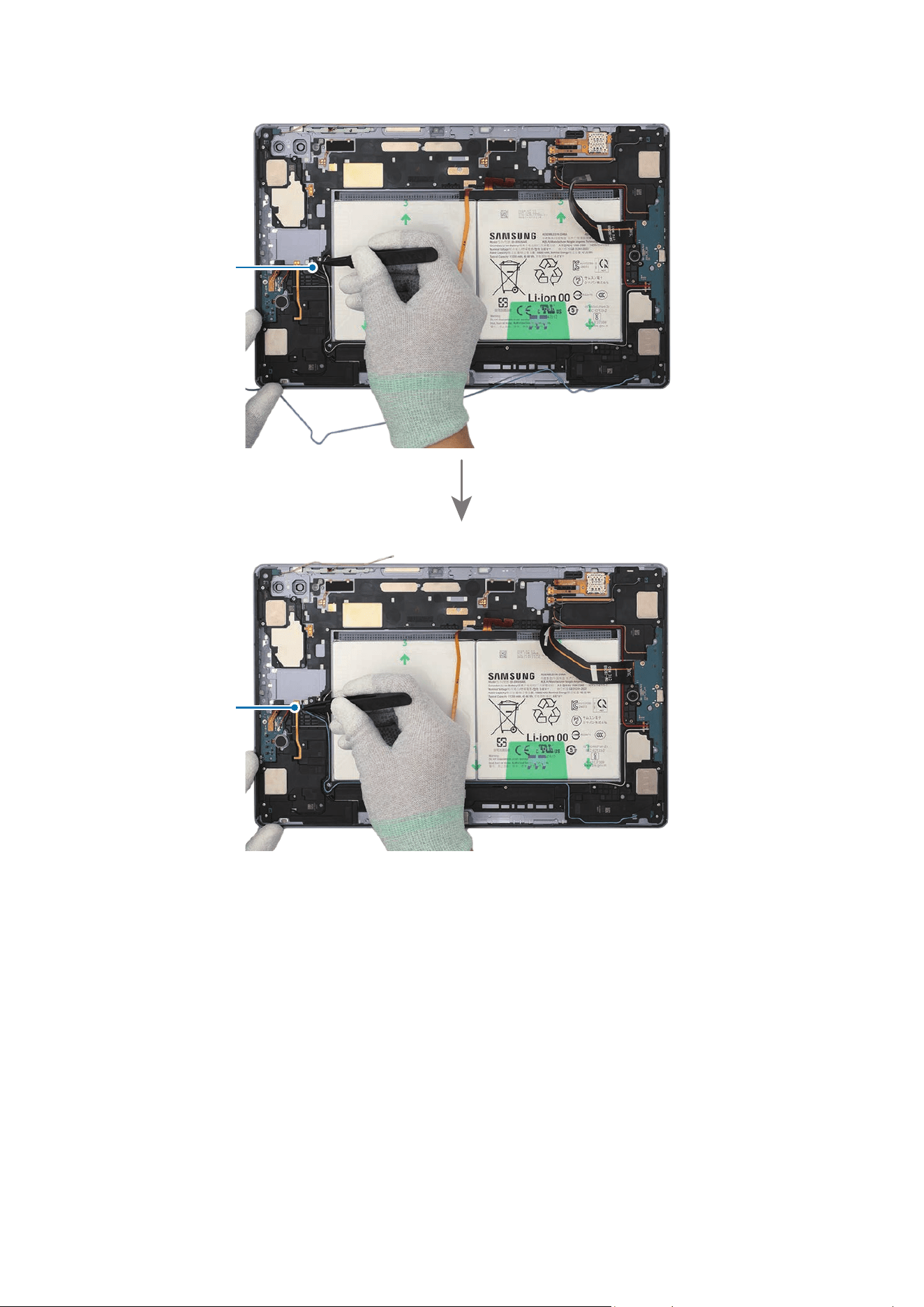
Disassembly and Assembly
294
Coaxial cable
(White)
Coaxial cable
(Blue)
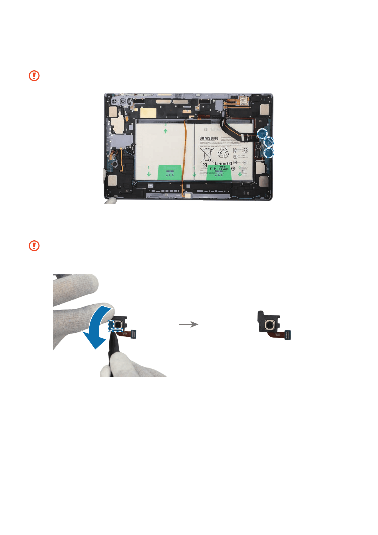
Disassembly and Assembly
295
40
Check the screw 3443 (3 ea) and fasten them on the charging port using a cross-head
screwdriver.
Be careful not to damage the charging port and near components.
41
If you use the existing rear wide camera as it is, remove all adhesive tapes on the
bottom of the camera using the tweezers.
•
Be careful not to damage the camera lens.
•
Be careful not to damage and scratch the camera module.
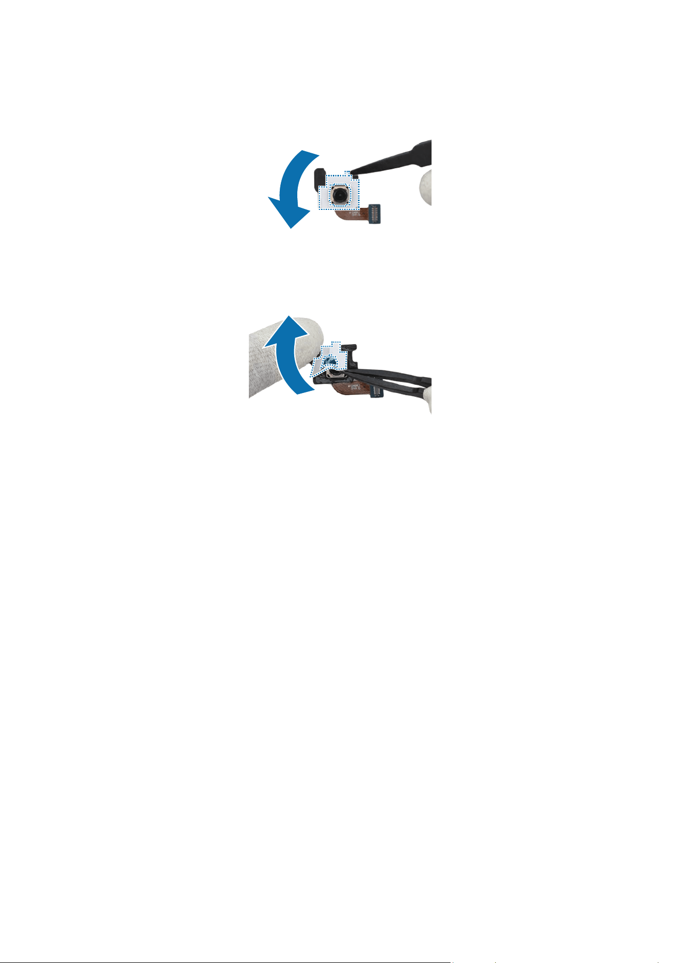
Disassembly and Assembly
296
42
Using the tweezers, remove the release film from the new wide camera adhesive tape
and attach it to the bottom of the wide camera.
43
Using the tweezers, hold the protruding release film of the attached tape and
carefully remove it.
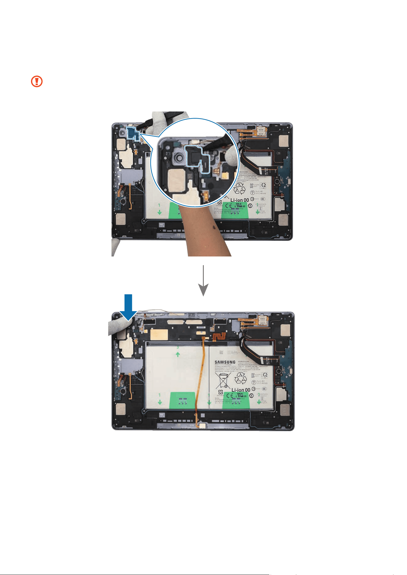
Disassembly and Assembly
297
44
Using the tweezers and your fingers, gently insert the wide camera in the camera
hole so that the lens faces backward.
•
Be careful not to damage the camera lens and near components.
•
Be careful not to damage and scratch the camera module.
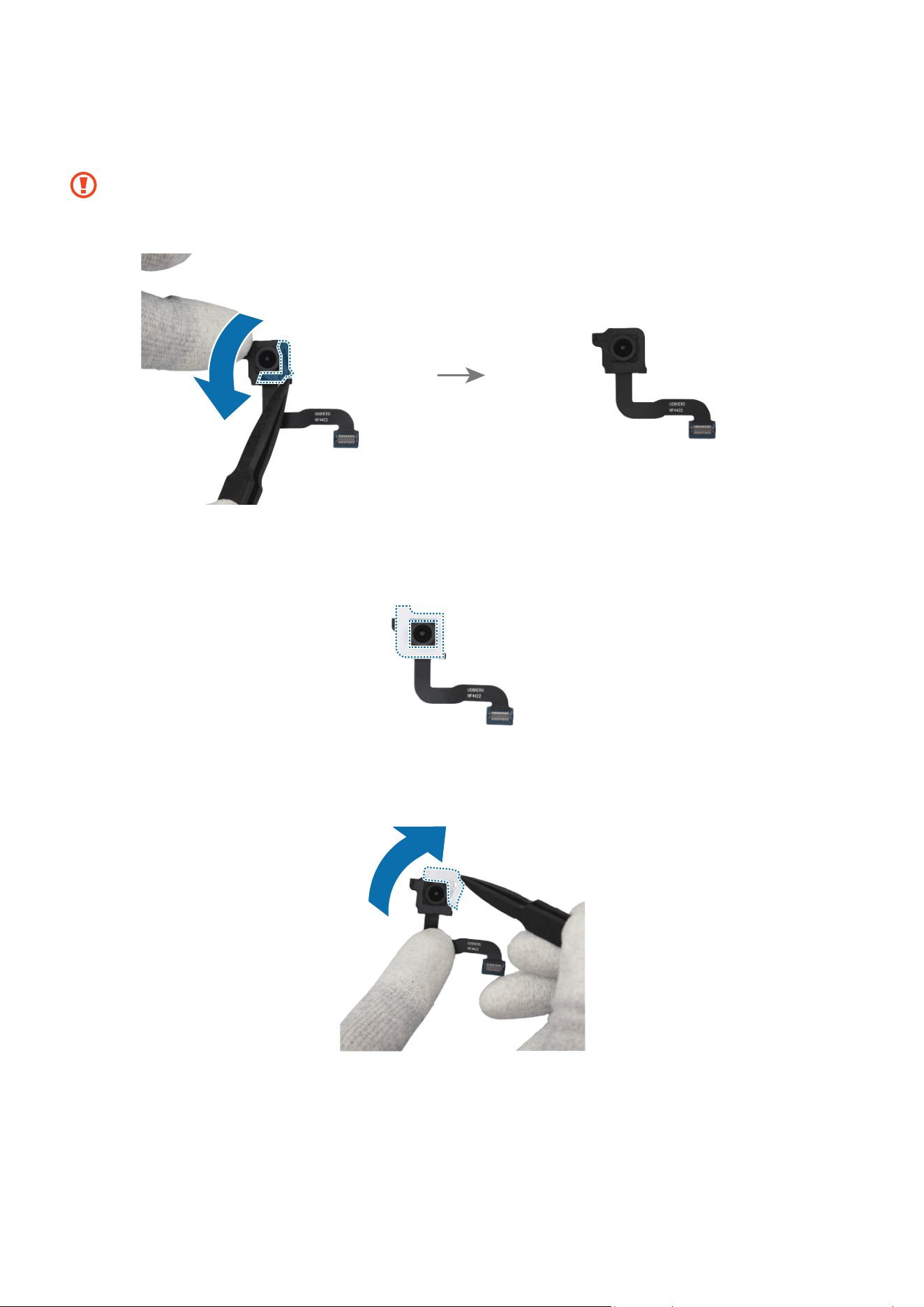
Disassembly and Assembly
298
45
If you use the existing rear ultra wide camera as it is, remove all adhesive tapes on the
bottom of the camera using the tweezers.
•
Be careful not to damage the camera lens.
•
Be careful not to damage and scratch the camera module.
46
Using the tweezers, remove the release film from the new ultra wide camera
adhesive tape and attach it to the bottom of the ultra wide camera.
47
Using the tweezers, hold the protruding release film of the attached tape and
carefully remove it.
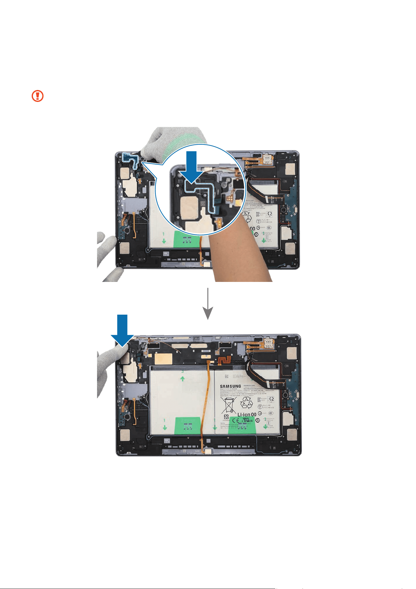
Disassembly and Assembly
299
48
Using the tweezers and your fingers, gently insert the ultra wide camera in the
camera hole so that the lens faces backward. Press down on the rear cameras with
your fingers softly so that the cameras can be assembled completely.
•
Be careful not to damage the camera lens and near components.
•
Be careful not to damage and scratch the camera module.

Disassembly and Assembly
300
49
Place the main board to the exact position and assemble it to the back cover module.
•
The cables have to positioned outside so as not to interfere when assembling
the main board.
•
Be careful not to damage the main board and near components.
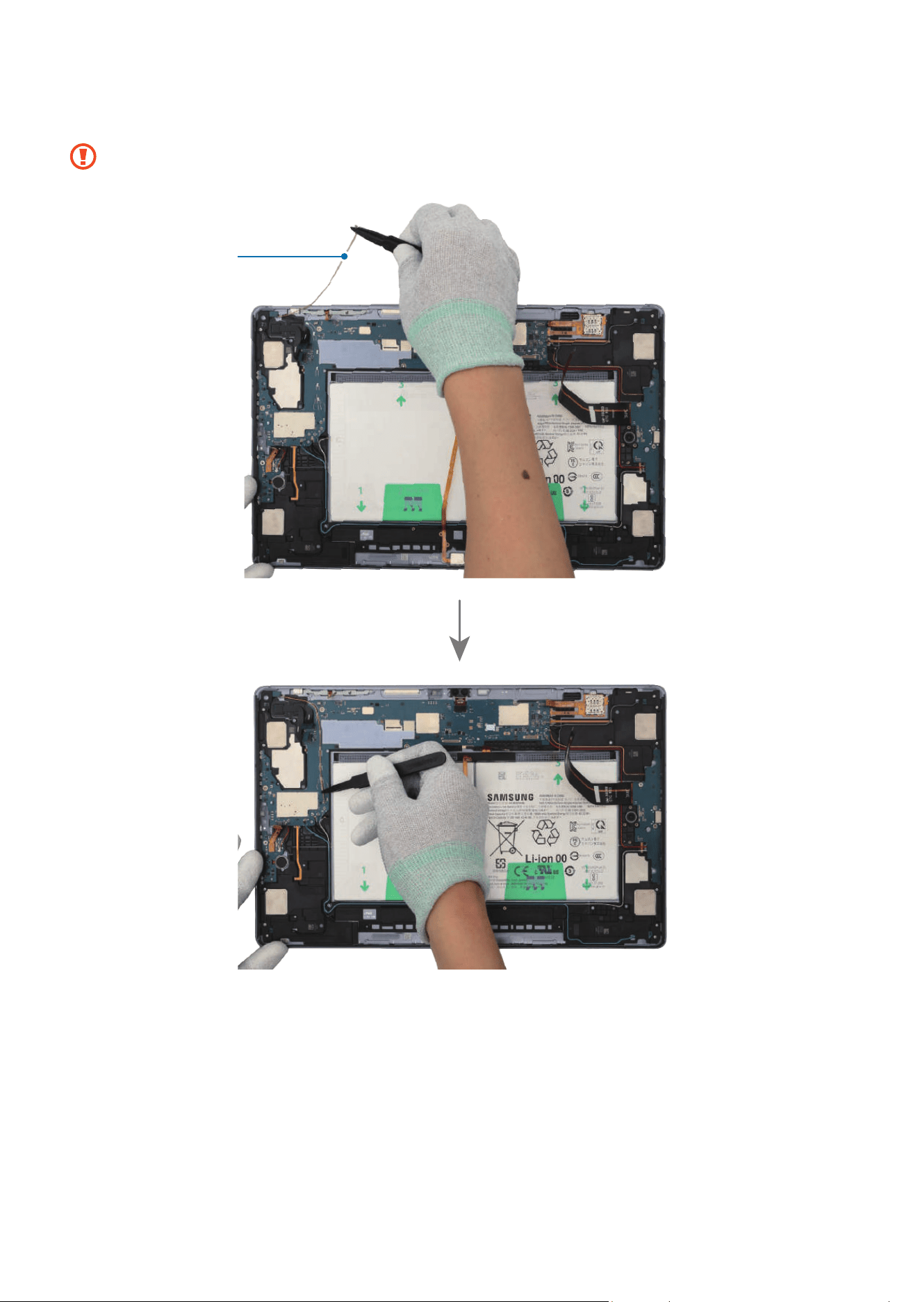
Disassembly and Assembly
301
50
Using the tweezers, connect the coaxial cable (Orange) to the main board.
Be careful not to damage the cables and near components.
Coaxial cable
(Orange)
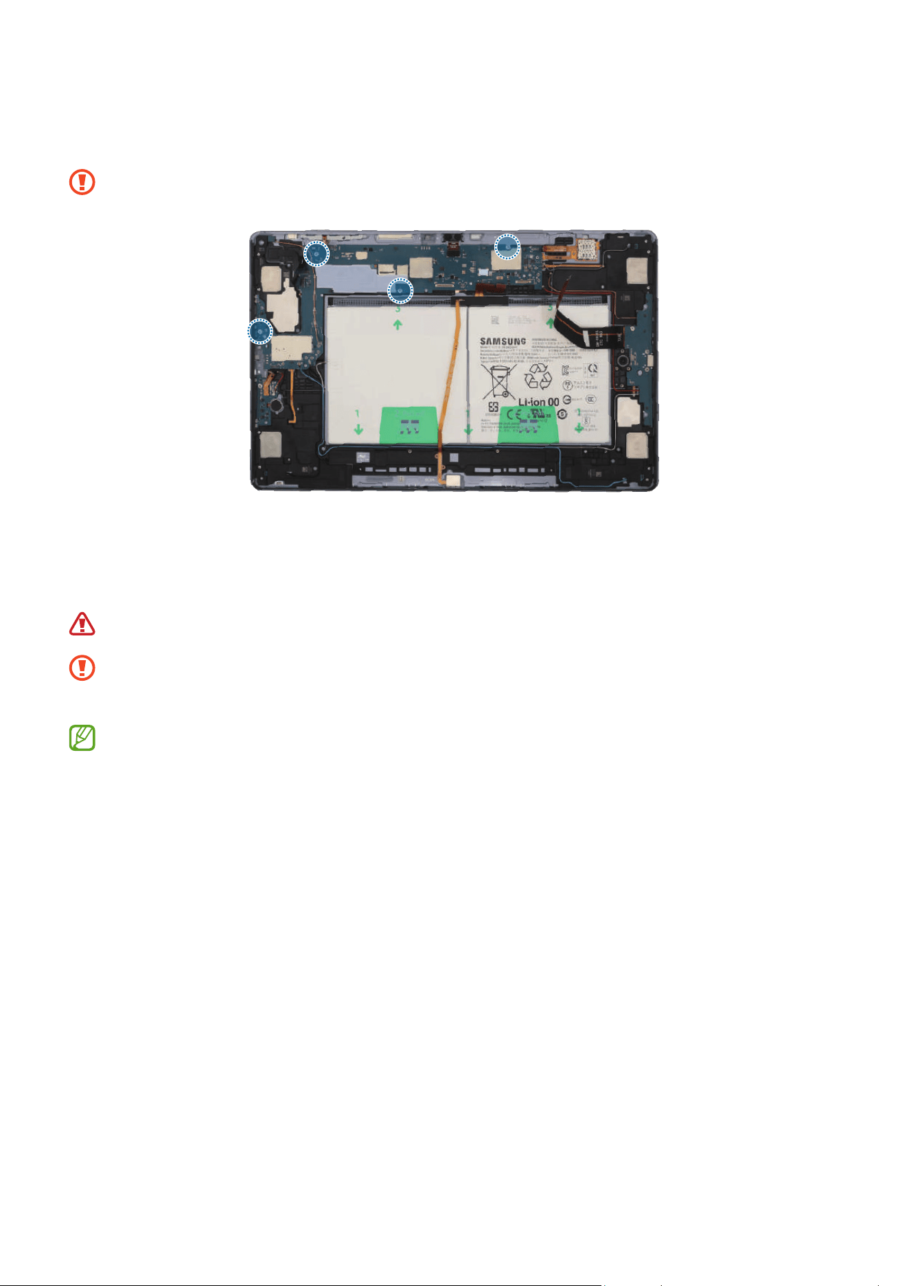
Disassembly and Assembly
302
51
Check the screw 3463 (4 ea) and fasten them on the main board using a cross-head
screwdriver.
Be careful not to damage the main board and near components.
52
Using the tweezers, connect the 8 connectors and the 3 coaxial cable connectors
(Orange/Black/Red) to the main board. For the 5G or LTE devices, connect the
additional 5 coaxial cable connectors (Blue/White/Grey/Orange/Red).
Be careful not to damage the battery.
•
Be careful not to damage the cable while connecting the connectors.
•
Be careful not to damage the near components.
•
The 5 coaxial cables (Blue/White/Grey/Orange/Red) are only available for the
5G or LTE devices.
•
The cables and connectors may vary depending on the country, region, or
specifications.

Disassembly and Assembly
303
Coaxial cable
(White)
Coaxial cable
(Blue)
Coaxial cable
(Grey)
Coaxial cable (Red)
Coaxial cable
(Orange)
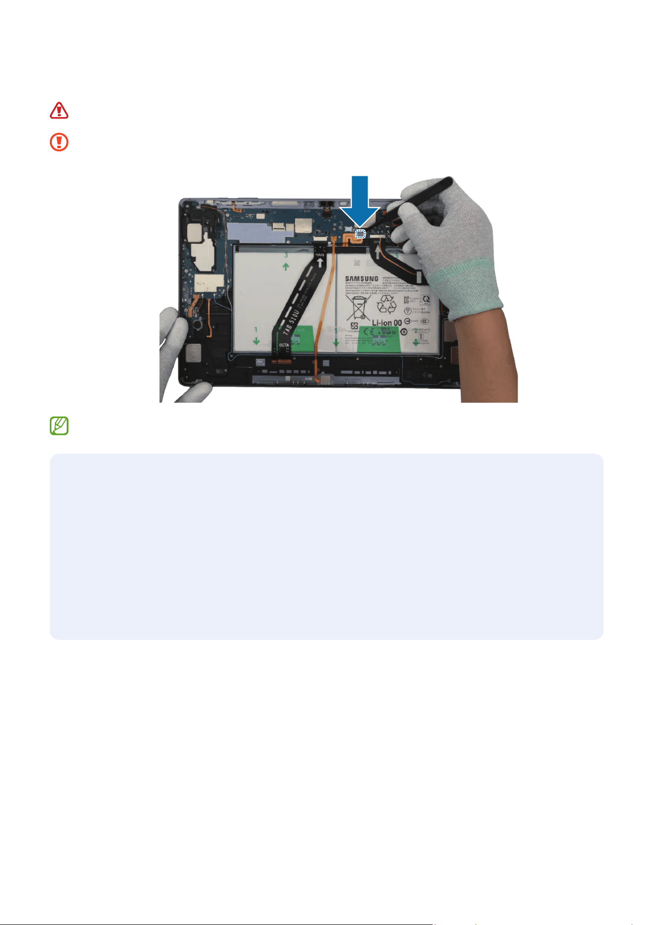
Disassembly and Assembly
304
53
Connect the battery connector to the main board.
Be careful not to damage the battery.
Be careful not to damage the battery connector and near components.
Reassemble the Bracket, Screen and SIM Card Tray to complete assembly.
After reassembling
•
Check whether the parts or sensors in the device work properly with the Self
Repair Assistant app after repairing and assembling your device. Refer to
Calibrations for more information.
•
Visit a Samsung Service Centre when finding some issues from the calibration
results. However, you may incur additional charges if the device has a
malfunction because of DIY repairs.

This guide is a property of Samsung Electronics Co., Ltd.
Any unauthorised use of guide can be punished under applicable international and/or
domestic law.
© Samsung Electronics Co., Ltd.
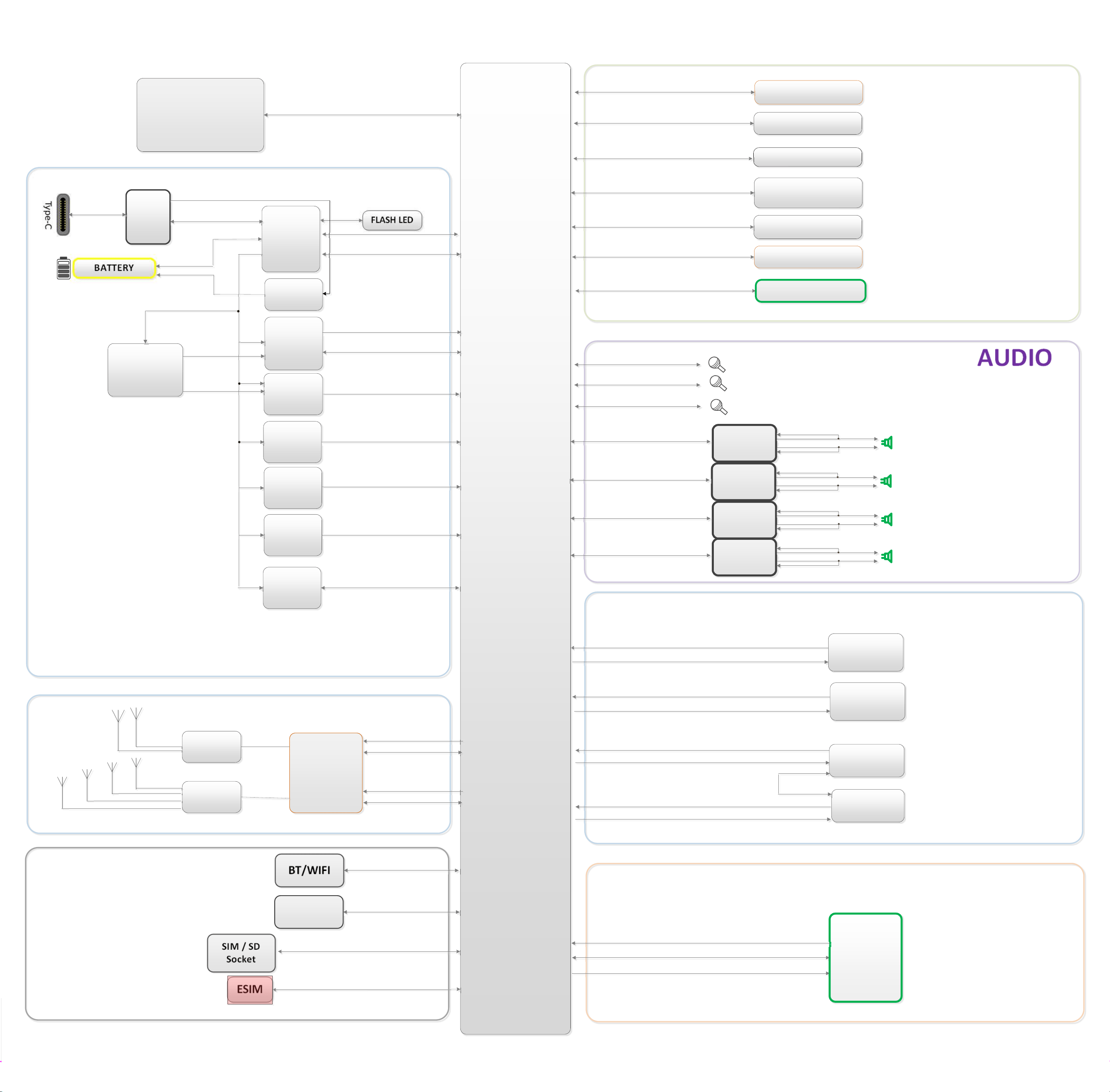
AP
REAR
WIDECAM
SENSOR
AUDIO
CAMERA
FRONT
UWCAM
FLASHLED
REAR
UWCAM
Memory
(Storage)
BT/WIFI
ESIM
SIM/SD
Socket
SIM/BT/WIFI/GPS
GRIPSENSOR
MAINMIC
2ndMIC
SPK
SPKAmp
BATTERY
POWER
MAIN
PMIC
Direct
Charger
DCDC #1
Sub
PMIC
Magnetic
6axis
FingerPrintSensor
Cover_DETHALL_IC
Light#1
Light#2
DISPLAY
MAIN
Display
+
TSP
IFPMIC
OVP
RF
LPAMid
TRANSCIEVER
LFEMid
3rdMIC
SPKAmp
SPKAmp
SPKAmp
FRONT
WIDECAM
GPS
SM‐X920(WIFIonly)Modelnotapplied
DCDC #2
DCDC #3
BuckBooster
ClockIC

