Page 1
PRODUCT INFORMATION:
INTENDED USE OF THE TOOL
WARNING
DO NOT DISCARD – GIVE TO USER
LIFETIME WARRANTY
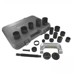
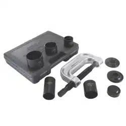
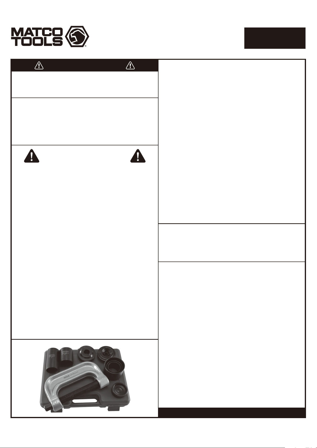
BALL JOINT SERVICE TOOL SET
WITH 4 WHEEL DRIVE ADAPTER SET
BPS400
When unpacking, check the parts diagram and part number
listing on page 6 to make sure all parts are included. If any
parts are missing or damaged, please call your distributor.
BEFORE USE
Study, understand and follow all instructions provided with
this product. Read these instructions carefully before
installing, operating, servicing or repairing this tool. Keep
these instructions in a safe accessible place.
This tool set is designed for removal and installation of
press-fit parts such as ball joints, universal joint and truck
brake anchor pins on cars and light trucks that have press-fit
type ball joints without the need to remove the control arm
from the vehicle. Do not use this tool outside of the designed
intent. Never modify the tool for any other purpose or use.
Caution: To help prevent personal injury
• Use of this product can expose you to chemicals including
ethylene glycol, gasoline vapors and engine exhaust, which are
known to the State of California to cause cancer, birth defects, or
reproductive harm. For more information, visit
www.P65Warnings.ca.gov. Always wear ANSI approved safety
equipment, safety glasses and clothing when using this product.
Study, understand, and follow all instructions provided with this
product. Failure to read and follow all warnings and operating
instructions may result in damages and serious injury or death.
• Always wear ANSI approved goggles when using this product.
(Users and Bystanders).
• Never use this tool for any application other than for
which it was designed.
• Only use accessories designed for this tool.
• Never alter or modify this tool in any way.
• Improper operation and/or maintenance of the tool, modification
of the tool, or use of the tool with accessories not designed for it
could result in serious injury or death.
• Always select the correct accessories of the correct size and design
for the job that you are attempting to perform.
• Always work in a clean, safe, well-lit, organized and adequately
equipped area.
• Do not begin repairs without assurance that vehicle is in secure
position, and will not move during repair.
WARNING
The manufacturer warrants this product to the original user
against defective material or workmanship for lifetime from
the date of purchase.
The manufacturer reserves the right to determine whether
the part or parts failed because of defective material,
workmanship or other causes. Failures caused by accident,
alteration, or misuse are not covered by this warranty.
The manufacturer, at its discretion, will repair or replace
products covered under this warranty free of charge. Repairs
or replacements of products covered under this warranty are
warranted for the remainder of the original warranty period.
The manufacturer or its authorized service representatives
must perform all warranty repairs. Any repair to the product
by unauthorized service representatives voids this warranty.
The rights under this warranty are limited to the original user
and may not be transferred to subsequent owners.
This warranty is in lieu of all other warranties, expressed or
implied, including warranties of merchantability and fitness
for a particular purpose. Some states do not allow the
exclusion or limitations of incidental or consequential
damages, so the above limitations may not apply to you.
• The heavy duty tool set is excellent for removal and
installation of press-fit parts such as ball joints,
universal joint and truck brake anchor pins
• Remove even rusted and corroded parts
• Set contains C-frame press, 3 receiver tubes sizes:
1-3/4" x 2", 1-3/4" x 2-1/2" & 2-1/4" x3", installation and
removing adapters
• Set also includes: 4-wheel drive ball joint service kit
that allows service for 1967 through current 1/2 and 3/4 ton
4WD vehicles having the Dana 44 front axle (found on
Ford, GM, Dodge, IHC and Jeep vehicles)
• Blow molded case for easy storage and transport
Made in China
to Matco specifications
Page 2
BALL JOINT SERVICE TOOL SET
WITH 4 WHEEL DRIVE ADAPTER SET
BPS400
Control
Arm
Ball
Joint
Installing Adaper
Receiving Tube
Removing Adapter
Figure 1
Figure 2
Figure 4
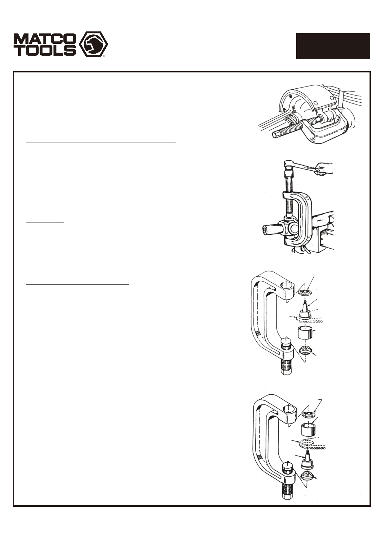
OPERATING INSTRUCTIONS:
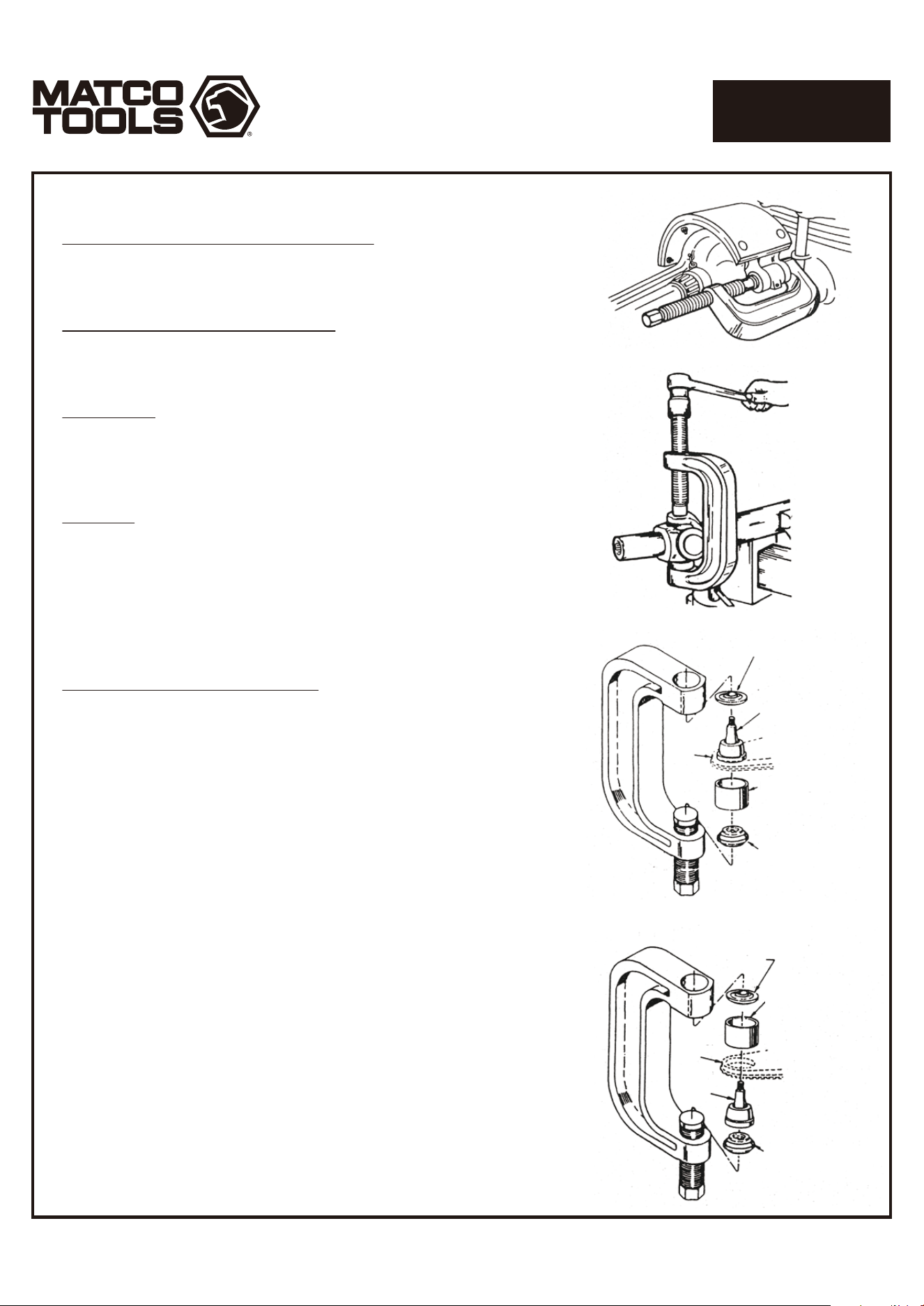
Brake Anchor Pin Removal and Installation
1. Remove all lock ring retainers from the brake anchor pins.
2. Position the C - Frame press over the brake spider as shown in Figure 1.
3. Tighten the forcing screw until the anchor pin is removed.
"U" Joint Assembly and Disassembly
The basic C - Frame press is used to service the "U" joints
on most cars and light trucks. The "U" joints can be serviced
either on or off the vehicle.
Disassembly
1. Remove any external and/or internal lock rings.
2. Position the C - Frame press around the drive shaft yoke, and
tighten the forcing screw until the first bearing is removed.
3. Reposition the C - Frame and remove the second bearing.
Assembly
1. Clean all dirt and oil from the yoke area.
2. Align the replacement bearing the C - Frame press as straight
as possible over the yoke. Press the replacement bearing into
the yoke, and reassemble the external/internal lock ring.
3. Reposition the C - Frame press and second replacement
bearing as straight as possible over the yoke, and press the
bearing into the yoke. Reassemble external/internal lock ring.
Ball Joint Removal and Installation
This tool set is designed for use on all cars and light trucks that
have press-fit type ball joints. It will help the user remove and
install ball joints without the need to remove the control arm
from the vehicle.
NOTE: Some cars and light trucks may have the upper ball joint
spot-welded to the control arm. The weld must be cut before
attempting to remove the ball joint.
Removal (Item numbers refer to the parts list on page 6)
1. Assemble the ball joint press over the control arm as
shown in Figure 3. Select the correct size receiving tube, and
position it under the vehicle ball joint as shown.
2. Tighten the forcing screw until the receiving tube contacts the
control arm. Check the alignment of all tooling and components,
and continue tightening the forcing screw until the ball joint
is removed.
Installation
1. Clean the control arm and coat the I.D. with a suitable lubricant.
2. Insert the replacement ball joint as straight as possible into the
vehicle control arm.
3. Assemble the ball joint press components as shown in Figure 4.
Position the receiving tube, and tighten the forcing screw.
Check the alignment of all tooling and components, and continue
tightening the forcing screw until the ball joint is firmly seated.
Installing Adapter
Ball Joint
Receiving Tube
Control
Arm
Removing Adapter
Figure 3
EL USO DE LA HERRAMIETA
Estudie, entienda y siga todas las instrucciones que se proveen
con este producto. Lea las instrucciones detenidamente antes
de instalar, operar, dar servicio o reparar esta herramienta.
Guarde estas instrucciones en un lugar seguro y accesible.
ADVERTENCIA
El juego de adaptador de cojinete de la rueda delantera maestra es
para la extracción y el aislamiento del cojinete de la rueda con el
perno de transmisión y el adaptador del kit solamente. No modifique
ni reemplace ninguna pieza de este kit con piezas extrañas. No use
estas herramientas fuera de la intención diseñada. Nunca modifique
las herramientas para ningún otro propósito o uso.
Precaución: Para ayudar a evitar
lesiones a las personas
• El uso de este producto puede exponerlo a productos químicos
que incluyen etilenglicol, vapores de gasolina y gases de escape
del motor, que en el estado de California son causantes de cáncer,
defectos de nacimiento o daños reproductivos. Para obtener más
información, visite www.P65Warnings.ca.gov. Siempre use equipo
de seguridad aprobado por ANSI, gafas de seguridad y ropa
cuando use este producto. Estudie, comprenda y siga todas las
instrucciones proporcionadas con este producto. Si no lee y sigue
todas las advertencias e instrucciones de funcionamiento puede
ocasionar daños y lesiones graves o la muerte.
• Siempre use guantes del tipo aprobado por la ANSI para trabajar
con esta herramienta (tanto usuarios como espectadores).
• Nunca utilice esta herramienta para cualquier otra cosa que no
sean las aplicaciones para lo que fue diseñada.
• Sólo utilice los accesorios diseñados para esta herramienta.
• No modifique o altere esta herramienta de ninguna manera.
• El funcionamiento y/o mantenimiento inadecuado de la
herramienta, la modificación, o la utilización de la herramienta
con accesorios inadecuados podrían causar lesiones graves o la
muerte.
• Siempre usar los correctos accesorios para el trabajo queUd. está
realizando.
• Trabaje siempre en un área limpia, segura, bien iluminada,
organizada y equipada adecuadamente.
• NUNCA empiece reparaciones sin estar seguro de que el vehículo
esté en posición segura y que no se mueva durante la reparación.
ADVERTENCIA
Page 3
INFORMACIÓN DEL PRODUCTO:
NO LO DESCARTE O DESECHE, ENTREGESELO AL USUARIO
GARANTÍA DE POR VIDA
CONJUNTO MAESTRO DE
ADAPTADORES PARA SERVICIO
DE FRENOS EN VEHICULOS CON
4 RUEDAS MOTRICES
BPS400
Cuando desempaque el producto, revise el diagrama y la
lista de piezas en página 6 para verificar que se hayan
enviado todas las piezas. De perder piezas o tener piezas
dañadas, favor llamar a su distribuidor inmediatamente.
DESEMPACADO
El fabricante garantiza que este producto el usuario original
contra cualquier defecto de material o mano de obra de por
vida desde la fecha de compra.
El fabricante se reserva el derecho a determinar si una pieza
o piezas fallaron debido a material defectuoso, mano de
obra, o por otras causas. Esta garantía no cubre fallas
causadas por accidentes, alteraciones o uso indebido.
El fabricante, a su entera discreción, reparará o reemplazará
los productos cubiertos por esta garantía sin costo alguno.
Las reparaciones o reemplazos de productos cubiertos por
esta garantía quedan garantizados durante el resto del
periodo original de garantía.
El fabricante o sus representantes autorizados de servicio
deben llevar a cabo todas las reparaciones de garantía. Toda
reparación hecha al producto por representantes de servicio
no autorizados invalida la presente garantía. Los derechos
que ampara esta garantía están limitados al usuario original
y no se pueden transferir a dueños posteriores.
Esta garantía reemplaza a todas las demás garantías
expresas o implícitas, incluyendo garantías de
comercialización e idoneidad para un propósito particular.
Algunos estados no permiten la exclusión o limitaciones de
daños incidentales o imprevistos, de manera que las
limitaciones mencionadas anteriormente pueden no ser
aplicables en su caso.
• Este conjunto de herramientas de mayor potencia es
excelente para retirar e instalar piezas de ajuste a presión,
tales como rótulas, articulaciones universales y pernos de
anclaje de camiones
• Retira incluso partes oxidadas y corroídas
• El juego contiene Prensa en "C", 3 tubos receptores de
tamaños: 1-3/4" x 2", 1-3/4" x 2-1/2" & 2-1/4" x3",
adaptadores para instalación y remoción
• El Juego también incluye: Conjunto de Servicio de Junta
Esférica de 4 ruedas motrices que permite el servicio en
vehículos de 1967 al actual de 1/2 y 3/4 tonelada con el
eje delantero Dana 44 (que se encuentra en Ford, GM,
Dodge, IHC y Jeep)
• Estuche plástico moldeado para facilitar el almacenamiento
y el transporte
HECHO en China
para Matco especificaciones
Page 4
CONJUNTO MAESTRO DE
ADAPTADORES PARA SERVICIO
DE FRENOS EN VEHICULOS CON
4 RUEDAS MOTRICES
BPS400
Figura 1.
Figura 2
Instalación del
adaptador
Junta esférica
Recepción de tubo
Brazo de
control
Extracción del
adaptador
Figura 3
Brazo de
control
Junta
esférica
Instalación del
adaptador
Recepción de tubo
Extracción del
adaptador
Figura 4
MANUAL DE INSTRUCCIONES:
Desmontaje e instalación de pasadores de anclaje en el sistema de frenos
1. Retire todos los retenes del anillo de fijación de los pernos de anclaje de freno.
2. Coloque la prensa en forma de "C" sobre la araña de freno como se
muestra en la Figura 1.
3. Apriete el tornillo de fuerza hasta que se retire el perno de anclaje.
Ensamblado y desmontaje de las junturas en "U"
La prensa básica en forma de "C" se utiliza para dar servicio a las junturas
en "U" en la mayoría de los automóviles y camiones ligeros. Las junturas
en "U" pueden ser atendidos ya sea dentro o fuera del vehículo.
Desmontaje
1. Retire los anillos de bloqueo externo y/o interno.
2. Coloque la prensa "C" alrededor del yugo del eje de transmisión y
apriete el tornillo de fuerza hasta que retire el primer cojinete.
3. Reposicione la prensa en C y retire el segundo cojinete.
Ensamblado
1. Limpie toda la suciedad y el aceite de la zona del yugo.
2. Alinee el nuevo cojinete con la prensa "C" tan recto como sea posible
sobre el yugo. Presione el cojinete de repuesto en el yugo y vuelva
a montar el anillo de seguridad externo/interno.
3. Reposicione la prensa "C" y el segundo cojinete de repuesto
repitiendo toda la maniobra como con el primer cojinete.
Instalación y remoción de rotulas
Este conjunto de herramientas está diseñado para uso en automóviles
y camionetas que tienen rótulas tipo ajuste a presión. Esto ayudará al
usuario a desmontar e instalar junturas de rótula sin la necesidad de
retirar el brazo de control del vehículo.
NOTA : Algunos coches y camiones ligeros pueden tener la rótula
superior soldada por puntos al brazo de control. La soldadura se debe
cortar antes de intentar quitar la rótula.
Remoción (Diferentes piezas se describen en la lista de la hoja 6)
1. Montar la prensa "C" en el brazo de control como se muestra en la
Figura 3. Seleccione el tubo receptor del tamaño correcto, y colóquelo
bajo la rótula del vehículo como se muestra.
2. Apriete el tornillo de presión hasta que el tubo receptor haga contacto
con el brazo de control. Compruebe la alineación de todas las
herramientas y componentes y continúe apretando el tornillo de fuerza
hasta que se retire la rótula.
Instalación
1. Limpie el brazo de control y cubra el I.D. con un lubricante adecuado.
2. Inserte la rótula de reemplazo lo más recta posible en el brazo de
control del vehículo.
3. Ensamble todos los componentes de la rotula en la prensa "C",
como se muestra en la Figura 4. Coloque el tubo receptor y apriete
el tornillo de fuerza. Compruebe la alineación de todas las
herramientas y componentes y continúe apretando el tornillo de
fuerza hasta que la rótula este firmemente asentada.

Page 5
BALL JOINT SERVICE TOOL SET
WITH 4 WHEEL DRIVE ADAPTER SET
BPS400
WARNING
ADVERTENCIA
Caution: To help prevent personal injury
• Use of this product can expose you to chemicals including ethylene glycol, gasoline vapors and engine exhaust, which are known
to the State of California to cause cancer, birth defects, or reproductive harm. For more information, visit www.P65Warnings.ca.gov.
Always wear ANSI approved safety equipment, safety glasses and clothing when using this product. Study, understand, and follow
all instructions provided with this product. Failure to read and follow all warnings and operating instructions may result in
damages and serious injury or death.
• Always wear ANSI approved goggles when using this product. (Users and Bystanders).
• Never use this tool for any application other than for which it was designed.
• Only use accessories designed for this tool.
• Never alter or modify this tool in any way.
• Improper operation and/or maintenance of the tool, modification of the tool, or use of the tool with accessories not designed for it
could result in serious injury or death.
• Always select the correct accessories of the correct size and design for the job that you are attempting to perform.
• Always work in a clean, safe, well-lit, organized and adequately equipped area.
• Do not begin repairs without assurance that vehicle is in secure position, and will not move during repair.
• El uso de este producto puede exponerlo a productos químicos que incluyen etilenglicol, vapores de gasolina y gases de escape del
motor, que en el estado de California son causantes de cáncer, defectos de nacimiento o daños reproductivos. Para obtener más
información, visite www.P65Warnings.ca.gov. Siempre use equipo de seguridad aprobado por ANSI, gafas de seguridad y ropa
cuando use este producto. Estudie, comprenda y siga todas las instrucciones proporcionadas con este producto. Si no lee y sigue
todas las advertencias e instrucciones de funcionamiento puede ocasionar daños y lesiones graves o la muerte.
• Siempre use guantes del tipo aprobado por la ANSI para trabajar con esta herramienta. (tanto usuarios como espectadores).
• Nunca utilice esta herramienta para cualquier otra cosa que no sean las aplicaciones para lo que fue diseñada.
• Sólo utilice los accesorios diseñados para esta herramienta.
• No modifique o altere esta herramienta de ninguna manera.
• El funcionamiento y/o mantenimiento inadecuado de la herramienta, la modificación, o la utilización de la herramienta con
accesorios inadecuados podrían causar lesiones graves o la muerte.
• Siempre usar los correctos accesorios para el trabajo que Ud. está realizando.
• Trabaje siempre en un área limpia, segura, bien iluminada, organizada y equipada adecuadamente.
• NUNCA empiece reparaciones sin estar seguro de que el vehículo esté en posición segura y que no se mueva durante la
reparación.
AVERTISSEMENT
• L'utilisation de ce produit peut vous exposer à des produits chimiques, notamment l'éthylène glycol, les vapeurs d'essence et les
gaz d'échappement des moteurs, qui sont reconnus par l'État de Californie pour causer le cancer, des anomalies congénitales ou
des problèmes de reproduction. Pour plus d'informations, visitez www.P65Warnings.ca.gov. Toujours porter un équipement de
sécurité, des lunettes de sécurité et des vêtements homologués ANSI lors de l'utilisation de ce produit. Étudier, comprendre et
suivre toutes les instructions fournies avec ce produit. Ne pas lire et suivre tous les avertissements et instructions d'utilisation peut
entraîner des dommages et des blessures graves ou la mort.
• Toujours porter des lunettes à coques approuvées par l’ANSI lorsque vous utilisez ce produit. (Utilisateurs et Spectateurs).
• Ne jamais utiliser cet outil pour aucune application qui n’est pas conçue.
• Seulement utiliser les accessoires conçus pour cet outil.
• Ne jamais modifier cet outil.
• Le fonctionnement et/ou l’entretien incorrect de cet outil, la modification de cet outil, ou l’utilisation de cet outil avec les
accessoires non conçus pour lui devrait causer des blessures graves ou la mort.
• Toujours utiliser les accessoires adéquats pour le travail que vous effectuez.
• Toujours travailler dans un environnement propre, sécuritaire, bien éclairé, organisé et suffisamment équipé.
• NE JAMAIS commencer les réparations sans d’abord vous être assuré que le véhicule est en position sécurisée et ne bougera pas
lors de la réparation.
Precaución: Para ayudar a evitar lesiones a las personas
Mise en garde: Pour aider à prévenir les blessures
Page 6
BALL JOINT SERVICE TOOL SET
WITH 4 WHEEL DRIVE ADAPTER SET
BPS400
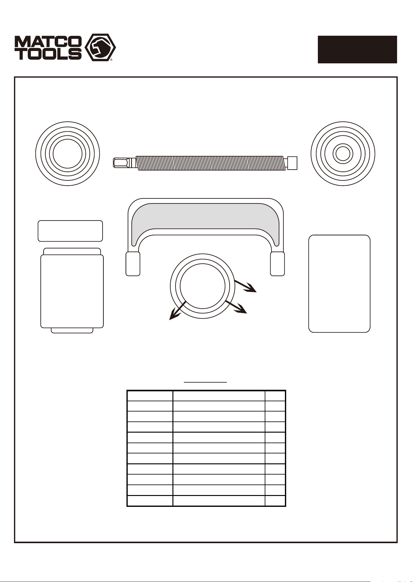
PARTS BREAKDOWN
Parts List
MBP1000-01A
MBP1000-02
MBP1000-03
MBP1000-04
MBP1000-05
MBP1000-08
MBP1000-09
MBP1000-10
MBP1000-16
MBP1000-21
PART NO DESCRIPTION QTY
C-Frame
1-3/4" x 2" Receiving Tube
1-3/4" x 2-1/2" Receiving Tube
2-1/4" x 3" Receiving Tube
Screw
Removal Adapter
Install Adapter
Install Cup Adapter
Receiving Cup
Install Cup
1
1
1
1
1
1
1
1
1
1
MBP1000-01A
MBP1000-02
MBP1000-03
MBP1000-04
MBP1000-05
MBP1000-08
MBP1000-10
MBP1000-16 MBP1000-21
MBP1000-09
809