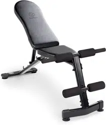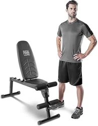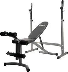
BCB 3890
BCB3890 Page 1
General Information
Warranty
HUPA International warrants your product for
a period of 1 year for the frame and 90 days
on all parts if the item is used for the intended
purpose, properly maintained and not used
commercially. Any alterations or incorrect
assembly of the product will void this warranty.
Proof of purchase must be presented for any
warranty validation (no exceptions). This
warranty applies to the original purchaser only
and is not transferable.
This warranty does not cover abuse or defects
caused during use, storage or assembly.
During the warranty period, HUPA International
reserves the right to:
a). provide replacement parts to the
purchaser in an effort to repair the item.
b). repair the product returned to our
warehouse (at the purchaser’s cost).
c). replace the product if neither of the two
previously mentioned actions effect repair.
This warranty does not cover normal wear and
tear on upholstery.
Questions
If you have any questions concerning the
assembly of your item or if any parts are
missing, please DO NOT RETURN THE
ITEM TO THE STORE OR CONTACT THE
RETAILER. Our dedicated customer service
staff can help you with any questions you may
have regarding the assembly of this unit and
can also mail you replacement parts.
Customer Support
Customer Support is open 9:00 a.m. to 5:00
p.m. (Pacific Time) Monday through Friday.
Please contact us by any of the following
means.
HUPA International Inc.
21717 Ferrero Parkway, Walnut, CA 91789
Telephone: (888) 266 - 6789
Fax: (909) 598 - 6707
Email: info@bodyflexsports.com
Safety
Before you undertake any exercise program,
please be sure to consult with your doctor.
Frequent strenuous exercise should be
approved by your doctor and proper use
of your product is essential. Please read
this manual carefully before commencing
the assembly of your product or starting to
exercise.
• Please keep all children away from this item
when in use. Do not allow children to climb or
play on them when they are not in use.
• Supervise teenagers while they use this unit.
• For your own safety, always ensure that there
is at least 3 feet of free space in all directions
around your product while you are exercising.
• Regularly check to see that all nuts, bolts and
fittings are securely tightened. Periodically
check all moving parts for obvious signs of
wear or damage.
• Clean only with a damp cloth, do not use
solvent cleaners. If you are in any doubt, do
not use your product; contact CUSTOMER
SUPPORT.
• Before use, always ensure that your product
is positioned on a solid, flat surface. If
necessary, use a rubber mat underneath to
reduce the possibility of slipping.
•
Always wear appropriate clothing and
footwear such as training shoes when
exercising. Do not wear loose clothing that
could become caught in moving parts during
exercise.
• Do not use this unit if it is not functioning
properly or if it is not fully assembled.
• Do not use this unit for commercial purposes.
Storage and Use
Your product is intended for use in clean
dry conditions. You should avoid storage in
excessively cold or damp places as this may
lead to corrosion and other related problems.
Weight Limit
• Before use, you must read and understand all
instructions & warnings stated in this Owner’s
Manual as well as posted on the equipment.
• It is the facility owner’s responsibility to properly
instruct users on the proper operation of the
equipment and to warn them of the potential
hazards.
• If at any time during exercise you feel faint, dizzy
or experience pain, stop and consult your
physician.
Assembling Tools
- Ruler with both metric and English measurements
- 2 x Adjustable Wrenches
- 1 x Philips (”Crosshead”) Screw Driver
The maximum weight capacity of this unit is
750 pounds (this includes the user's body weight).
• Maximum Olympic Weight Set: 300 lbs
• Maximum Body Weight: 300 lbs
• Maximum Weight on Leg Extension: 150 lbs
BEFORE ASSEMBLY
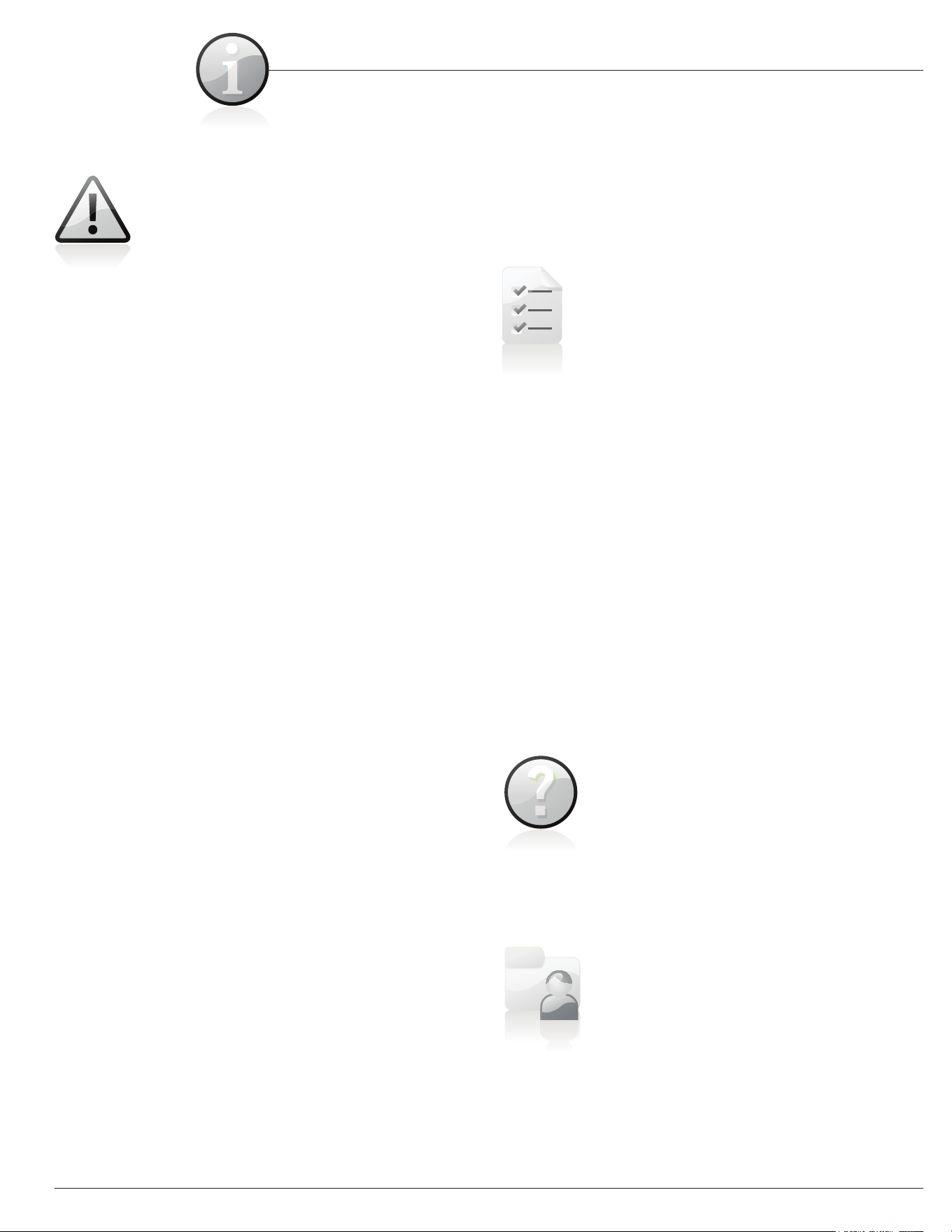
Nylon Lock Safety Nuts
A. It is only necessary to tighten the bolts and nuts to “finger tight” during the
assembly process. This will make it easier to complete certain steps by
allowing more tolerance for all the parts to fit properly.
B. Do not tighten all the nuts onto the bolts securely until after you have
completed assembly of your product.
C. Use wrenches, pliers, or ratchet and sockets to tighten the bolts and nuts.
D. The Nylon Nut should thread onto the Hex Bolt until the end of the Hex Bolt
has broken through the Nylon insert inside the Nut.
Take a few moments to familiarize yourself with the specific parts hardware
included with your product. Make sure all the parts and hardware are included in
the cartons and examine them for any damage that may have occurred in
transport. Some parts may be pre-assembled and pre-installed
Wiring and Loose Components
A. Check all wiring for rips and tears
B. Check the frame for any damage
C. Make sure all the hardware is included
Take a few minutes to familiarize yourself with the parts and hardware included with your product.
IMPORTANT PLEASE NOTE: MANY OF THE PARTS AND HARDWARE LISTED ON THE PARTS
LIST ARE ALREADY PRE-ASSEMBLED OR INSTALLED ON THE BENCH.
BEFORE ASSEMBLY
Tools required to assemble the machine:
• Two Adjustable Wrenches
• Two Allen Wrenches
BCB3890 Page 2
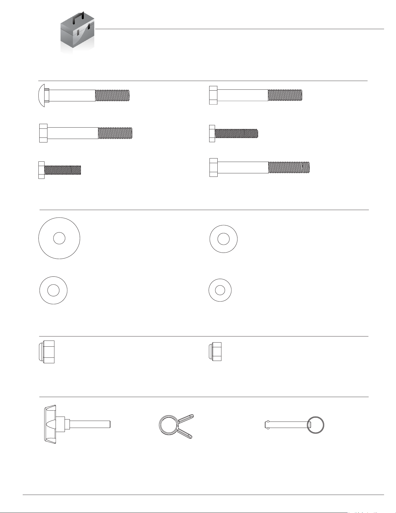
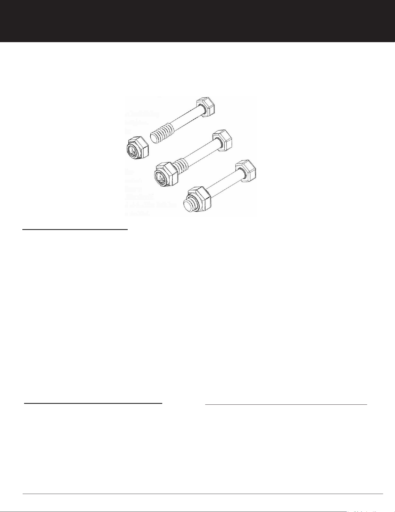
BOLT
WASHER
#20. Carriage Bolt (3/8”x2-7/8”) [8 Pieces]
#21. Hex Bolt (3/8"x3-1/8") [4 Pieces]
#22. Hex Bolt (3/8"x3") [1 Piece] #23. Hex Bolt (5/16"x1-1/2") [4 Pieces]
#24. Hex Bolt (5/16"x1-1/4") [4 Pieces]
#25. Lock Nut (3/8") [14 Pieces]
#26. Lock Nut (5/16") [2 Pieces]
#27. Large Curved Washer [4 Pieces]
#28. Curved
Washer (3/8") [12 Pieces]
#29. Washer (3/8") [3 Pieces]
#30. Washer (5/16") [8 Pieces]
#16. Lock Knob [2 Pieces
] #17. Quick Clip [1 Piece]
#19. Lock Pin [1 Piece]
#43. Hex Bolt (3/8"x3-5/8") [1 Piece]
NUT
Others
Hardware & Tool List
The following hardware is used to assemble your unit. Please take a moment to familiarize yourself with these items.
Please note, most of these parts are already pre-assembled on your unit. Do not be alarmed if you see parts on this
page that are not included in your hardware packet.
BCB3890 Page 3

Parts Listing
The following parts list describes all of the parts illustrated on the
exploded diagram on the following page. Please note, most of
these parts are already pre-assembled on your unit.
BCB3890 Page 4
# Description # Description
01 Right Upright Frame 24 Hex Bolt (5/16"x1-1/4")
02 Left Upright Frame 25 Lock Nut (3/8")
03 Rear Cross
Tube 26 Lock Nut (5/16")
04 Adjustable Upright Tube 27 Large Curved Washer
05 Main Frame 28 Curved Washer (3/8")
06 Leg Developer 29 Washer (3/8")
07 Backrest Adjustable Tube 30 Washer (5/16")
08 Bracket 31 End Cap (φ60 mm)
09 Rear Stab
ilizer 32 Foam Roller
10A 33 Round Spacer (
φ50-60 mm)
11 Olympic Adapter 34 Round
Inner Plug (φ60 mm)
12 Foam Rod Tube 35 Round
Inner Plug (φ50 mm)
13 Backrest Tube 36 Round
Inner Plug (φ25 mm)
14 Left Safety Hook 37 End Cap (φ25 mm)
15 R
ight Safety Hook 38 Bumper
16 Lock Knob 39 Square Inner Plug (25
mm)
17 Quick C
lip 40 Rectangular Inner Plug (15x30 mm)
18 Lock Pin with Rope 41 Seat Cushion
19 Lock Pin 42 Backrest Cushion
20 Carriage Bolt (3/8"x2
-7/8”)
21 Hex Bolt
(3/8"x3-1/8")
22 Hex Bolt (3/8"x3")
23 Hex Bolt (5/16"x1-1/2")
43 Hex Bolt (3/8"x3-5/8")
Fron
t Stabilizer
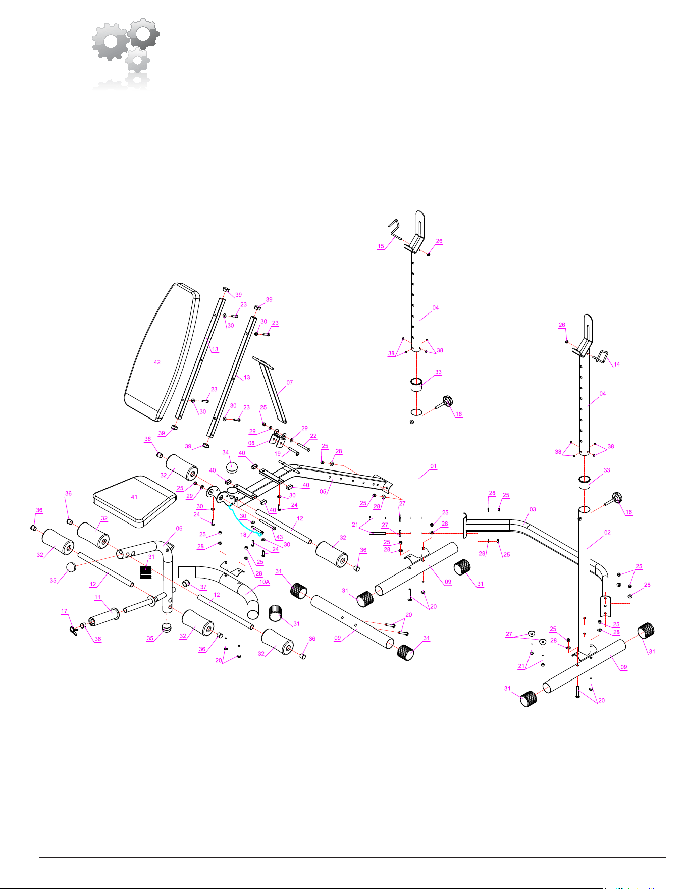
Exploded Diagram
The following diagram is provided to help you familiarize yourself with the parts and
hardware that will be used during the assembly process. Please note that not all of the
parts and hardware you see here will be used while you are assembling the machine
because some of these items are already pre-installed. Please continue to the next
page to begin the assembly process and use this page only as a reference guide for
parts and hardware.
BCB3890 Page 5
BCB3890 Page 6
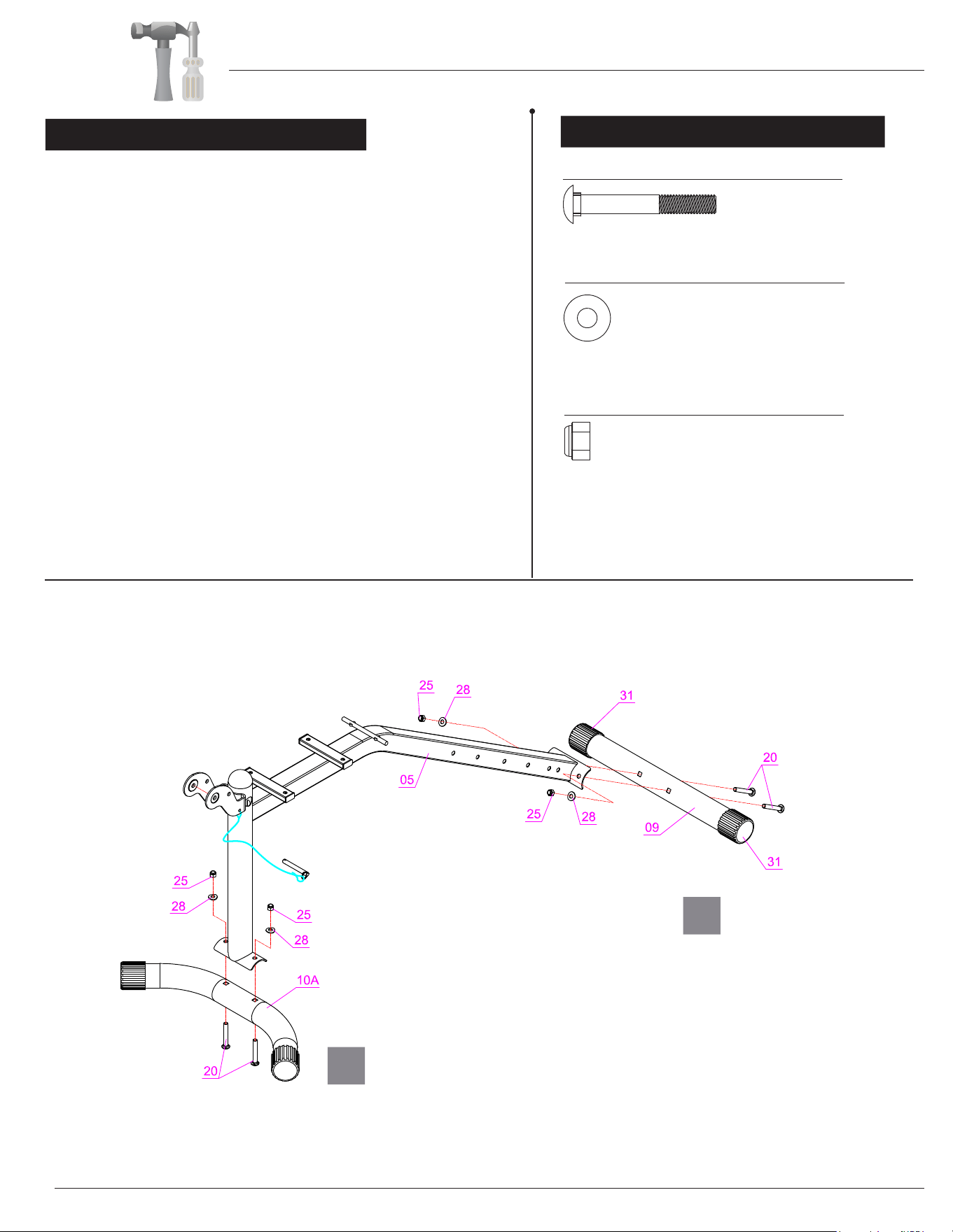
A s s e m b l y S t e p 1
Hardware Required
BOLT
WASHER
#20. Carriage Bolt (3/8”x2-7/8”) [4 Pieces]
#25. Lock Nut (3/8") [4 Pieces]
#28. Curved Washer (3/8") [4 Pieces]
A). Connect the Main Frame (#05) to the Rear Stabilizer
(#09) by inserting two Carriage Bolts (#20) up through
the Rear Stabilizer (#09) and Main Frame (#05) and
secure with two Curved Washers (#28) and two Lock
Nuts (#25).
B). Connect the Main Frame (#05) to the Front Stabilizer
(#10A) by inserting two Carriage Bolts (#20) up through
the Front Stabilizer (#10A) and Main Frame (#05),
securing with two Curved Washers (#28) and two Lock
Nuts (#25).
NUT
A
B
Assembly Instructions
Assembly Instructions
A
B
C
BCB3890 Page 7
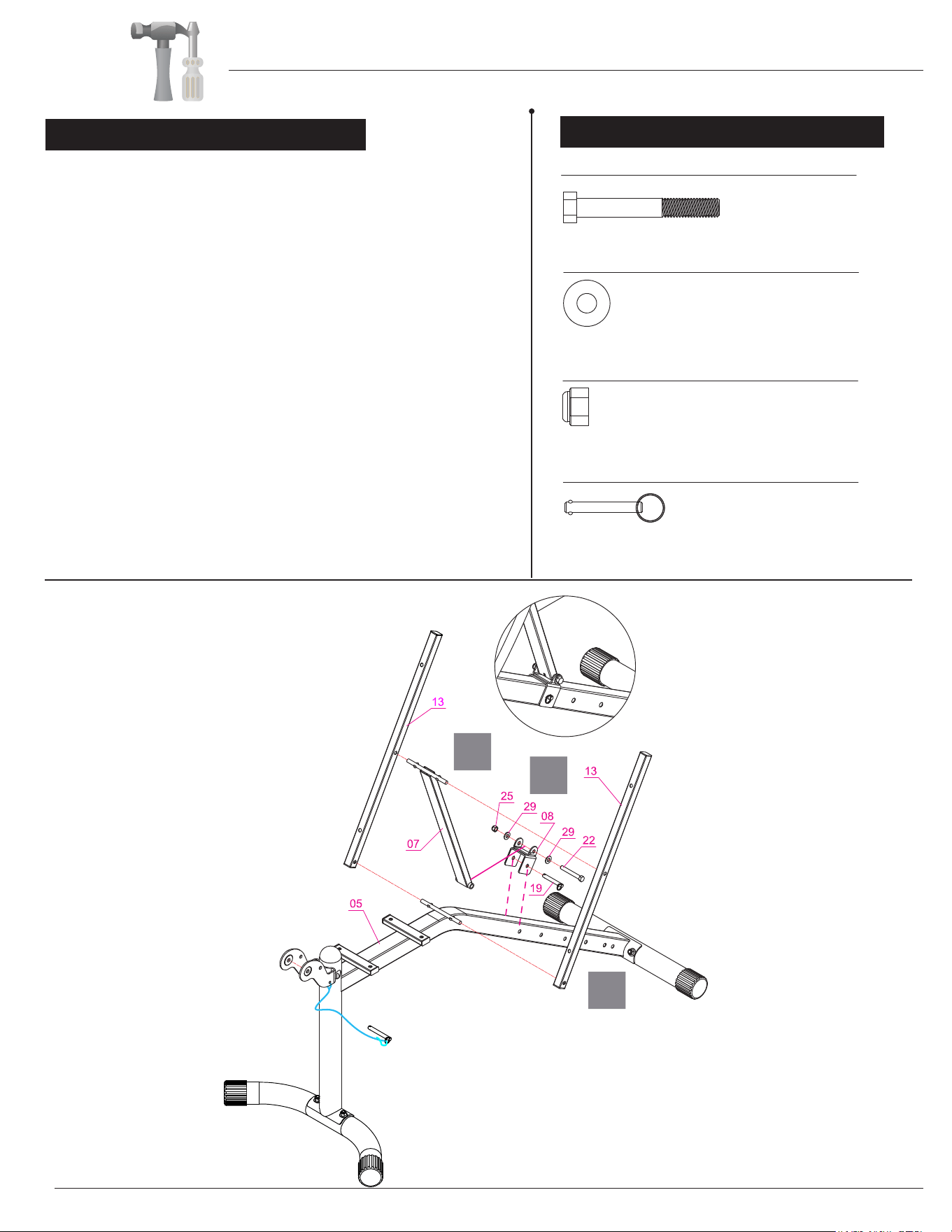
Assembly S tep 2
Hardware Required
BOLT
WASHER
NUT
#22. Hex Bolt (3/8"x3") [1 Piece]
#25. Lock Nut (3/8") [1 Piece]
#29. Washer (3/8") [2 Pieces]
#19. Lock Pin [1 Piece]
Others
A). Place the Bracket (#08) onto the rear declining portion
of the Main Frame (#05) as illustrated and secure by
inserting Lock Pin (#19) in through the Bracket (#08)
and the first set of holes of the Main Frame (#05).
B). With the help of an assistant, align the bottom end of
the Backrest Adjustable Tube (#07) to the holes on
the Bracket (#08) and secure by inserting one Hex
Bolt (#22) through one Washer (#29), the Bracket
(#08), the bottom end of the Backrest Adjustable
Tube (#07) all the way through the other hole on the
Bracket (#08) and secure using one Washer (#29)
and one Lock Nut (#25).
C). With the help of an assistant and using the diagram as
reference, attach one Backrest Tube (#13) to the left
side by inserting the hole in the center to the left
protruding small cylinder of the Backrest Adjustable
Tube (#07), and the hole at the bottom of the Backrest
Tube (#13) to the small cylinder of the Main Frame
(#05). Repeat this process with the second Backrest
Tube (#13) on the right side.
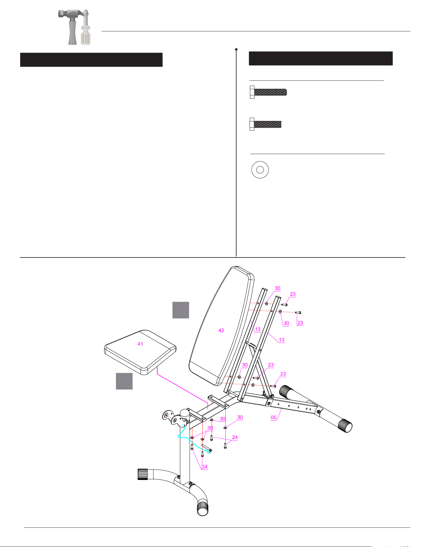
A s s e m b l y S t e p 3
BCB3890 Page 8
Hardware Required
BOLT
WASHER
#23. Hex Bolt (5/16"x1-1/2") [4 Pieces]
#24. Hex Bolt (5/16"x1-1/4") [4 Pieces]
#30. Washer (5/16") [8 Pieces]
A
B
A). Attach the Seat Cushion (#41) to the front section of
the Main Frame (#05) by inserting four Hex Bolts (#24)
through four Washers (#30) and up through the bottom
of the Main Frame (#05) and secure.
B). Next, attach the Backrest Cushion (#42) to the previously
assembled portion in
Assembly Step 2 (now connected
as an extension of the Main Frame (#05)) by inserting
four Hex Bolts (#23) through four
Washers (#30) from
the back of the Step 2 assembly, through the Backrest
T
ubes (#13) and the
Backrest Cushion (#42).
Assembly Instructions
Assembly Instructions
A
E
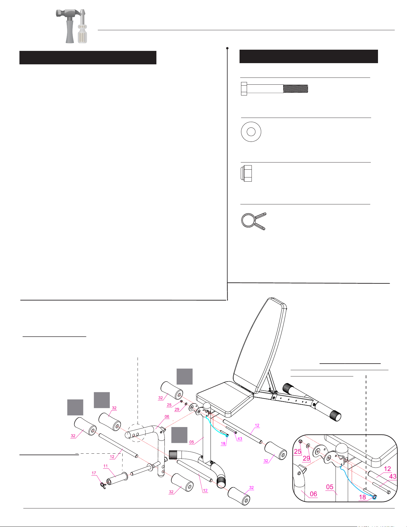
Rope (#18) whenever the bench is not in
* F O A M R O L L E R S
The Foam Roller Tube (#12) can be placed through either of these two
holes depending on your height. Simply remove one Foam Roller (#41)
from one end to reposition the location of the Foam Roller Tube (#12).
.
OLYMPIC ADAPTER
If you intend to use Olympic plates,
slide the Olympic Adapter (#11)
over the standard plate post and
secure it with one
(#17).
1" Quick Clip
C
D
BCB3890 Page 9
Please use the diagram and close-up diagram below for
reference to ensure proper assembly.
*For your safety and of those around you,
the Lock Pin with Rope (#18) should be
engaged into the hole as shown in close-up
drawing below whenever the bench is not in
use for exercises such as leg extensions.
Please also lock in the Lock Pin with
use, or, is left unattended.
17. Quick Clip [1 Piece]
A). Attach the Leg Developer (#06) to the bracket on the
Main Frame (#05). Secure by inserting through the front
hole as illustrated: one
Hex Bolt (#43) through the
Leg Developer (#06) and out the other end of the bracket
on the Main Frame (#05). Secure using one Washer
(#29) and one Lock Nut (#25).
B). Gather the three Foam Rod
Tubes (#12) and six Foam
Rollers (#32). Using one Foam Rod Tube(#12), on one
end, slide on one Foam Roller (#32).
Repeat this process with the other two Foam Rod Tubes
(#12) so that all three Foam Rod Tubes (#12) each have
one Foam Roller(#32) on one end.
C). Insert the free end of one of the Foam Rod Tubes (#12)
through either of the holes on the bottom of the Leg
Developer (#06) as illustrated. These hole options allow
you to configure the unit to your body height. If you are
tal
ler, you may want to use the most bottom hole. Then,
attach one Foam Roller (#32) to the free end of the
Foam Rod Tube (#12).
D). Repeat “C.” above with either of the holes on the
curve-extended portion of the Leg Developer (#06).
E). Then, repeat “C.” above through the hole on the top center
post of the Main Frame (#05).
BOLT
WASHER
NUT
#43. Hex Bolt (3/8"x3-5/8") [1 Piece]
#25. Lock Nut (3/8") [1 Piece]
#29. Washer (3/8") [1 Piece]
Others
Ass e m b l y S t e p 4
Hardware Required
Assembly Instructions
BCB3890 Page 10
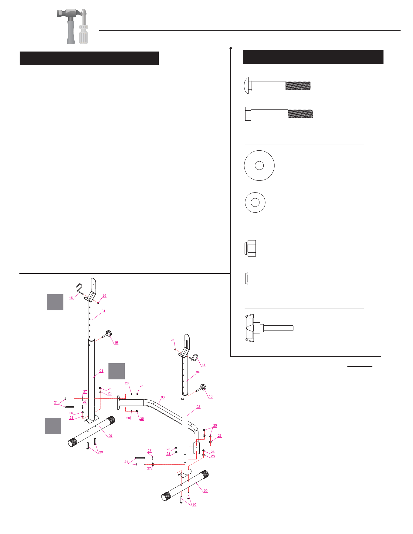
Others
#20. Carriage Bolt (3/8”x2-7/8”) [4 Pieces]
#21. Hex Bolt (3/8"x3-1/8") [4 Pieces]
#25. Lock Nut (3/8") [8 Pieces]
#26. Lock Nut (5/16") [2 Pieces]
#27. Large Curved Washer [4 Pieces]
#28. Curved Washer (3/8") [8 Pieces]
#16. Lock Knob [2 Pieces]
The assembly process is now complete. However, for your
own safety, please make sure to read this entire Owner’s
Manual which includes safety instructions and warnings, as
well as any safety/war
ning labels affixed to the product
before use.
For your safety, please visually and functionally inspect and
test the unit after assembly is complete.
A
C
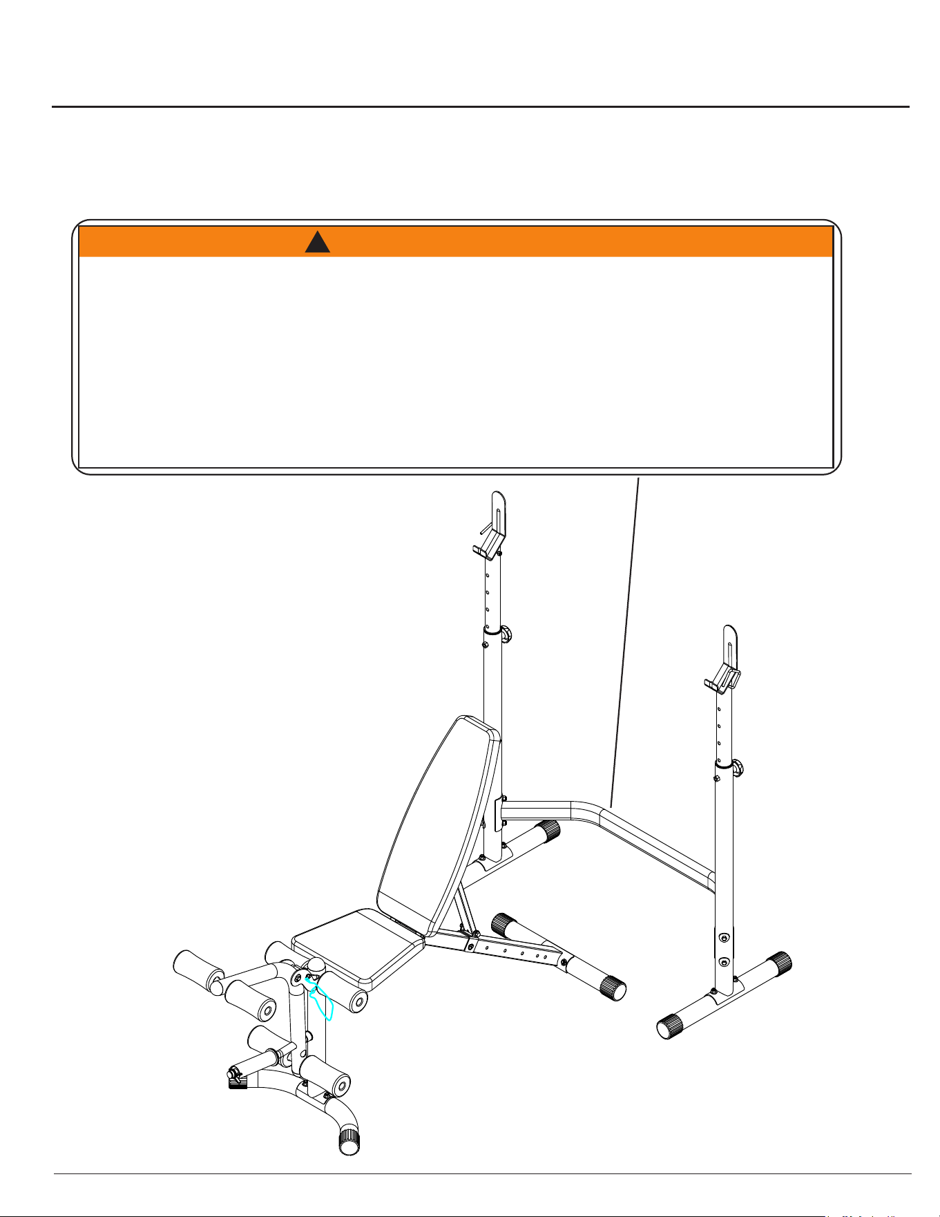
A s s e m b l y S t e p 5
Hardware Required
BOLT
WASHER
NUT
A). With the help of an assistant, attach the Right Upright
Frame (#01) to one Rear Stabilizer (#09) by inserting two
Carriage Bolts (#20) up through the Rear Stabilizer (#09)
and Right Upright Frame (#01) and secure with two
Curved Washers (#28) and two Lock Nuts (#25). Repeat
this process to assemble the Left Upright Frame (#02).
B). Connect the Right Upright Frame (#01) and Left Upright
Frame (#02) by using the Rear Cross
Tube (#03) in the
mid-span as illustrated. Beginning on the right side, insert
two Hex Bolts (#21) through two Large Curved Washers
(#27), and through the Right Upright Frame (#01), securing
with two Curved Washers (#28) and two Lock Nuts (#25).
Note: The Adjustable Upright Tubes (#04) are pre-installed
on the Right Upright Frame (#01) and the Left Upright
Frame (#02).Adjust the Adjustable Upright Tubes (#04)
to obtain the desired height and insert the Lock Knobs
(#16) on both sides to secure it in place. Always ensure that
after any adjustments are made, both sides are even and
level to prevent serious injury and even death.
C). Using the diagram as reference, insert the Right and Left
Safety Hooks (#15) and (#14) into the holes on top of both
Adjustable Upright Tubes (#04). Secure each using one
Lock Nut (#26) on each side.
Repeat this process to assemble the Left Upright Frame
(#02).
B

Safety & Maintenance
• Make sure all nuts, bolts, and screws are tightened prior to use.
• Be sure that all adjustment locking devices and safety devices are properly engaged prior to use!
• Never over-tighten the above-mentioned devices and parts to avoid damage to the unit.
• Check for loose parts and components and make proper adjustments prior to use.
• Check to see if there are any tears or bends in the welding or metal prior to use. If tears or bends
are found, do NOT use the unit and contact our CUSTOMER SUPPORT.
• Extreme care must be taken to not allow your feet, fingers, hair, clothing, and/or any loose items to be
snagged into any portion of the bike when the unit is in motion. Failure to follow these instructions
could result in serious injury, including the l
oss of fingers.
• Always wait for the pedals and other moving parts (which can gain great momentum during riding) to
come to a complete stop before dismounting the u
nit to avoid serious injury.
• Do not use solvent cleaners. If you are in any doubt, do not use your cleansing product;
contact CUSTOMER SUPPORT.
M a i n t e n a n c e & C a r e
• For any replacement warning labels, please contact our CUSTOMER SUPPORT at (888) 266-6789
or (909) 598-9876, or mail in a written request to:
HUPA International Inc. 21717 Ferrero Parkway,
Walnut, CA 91789. More detailed information about how to reach our CUSTOMER SUPPORT may
be found on Page 1 of the Owner’s Manual under
the “CUSTOMER SUPPORT” section.
• The specific Parts on your unit which may see possible signs of wear after prolonged use are listed as
follows (please check these parts before each use):
Seat Cushion (#41); Backrest Cushion (#42); Lock Knob (#16); Lock Pin (#18/19).
• Please review all safety instructions and warnings in this entire Owner’s Manual, as well as any
safety/warning labels affixed to the product before use.
SAFETY & WARNINGS
BCB3890 Page 11
Before use, you must read and understand all instructions & warning stated in this Owner's Manual as well as
posted on the equipment.
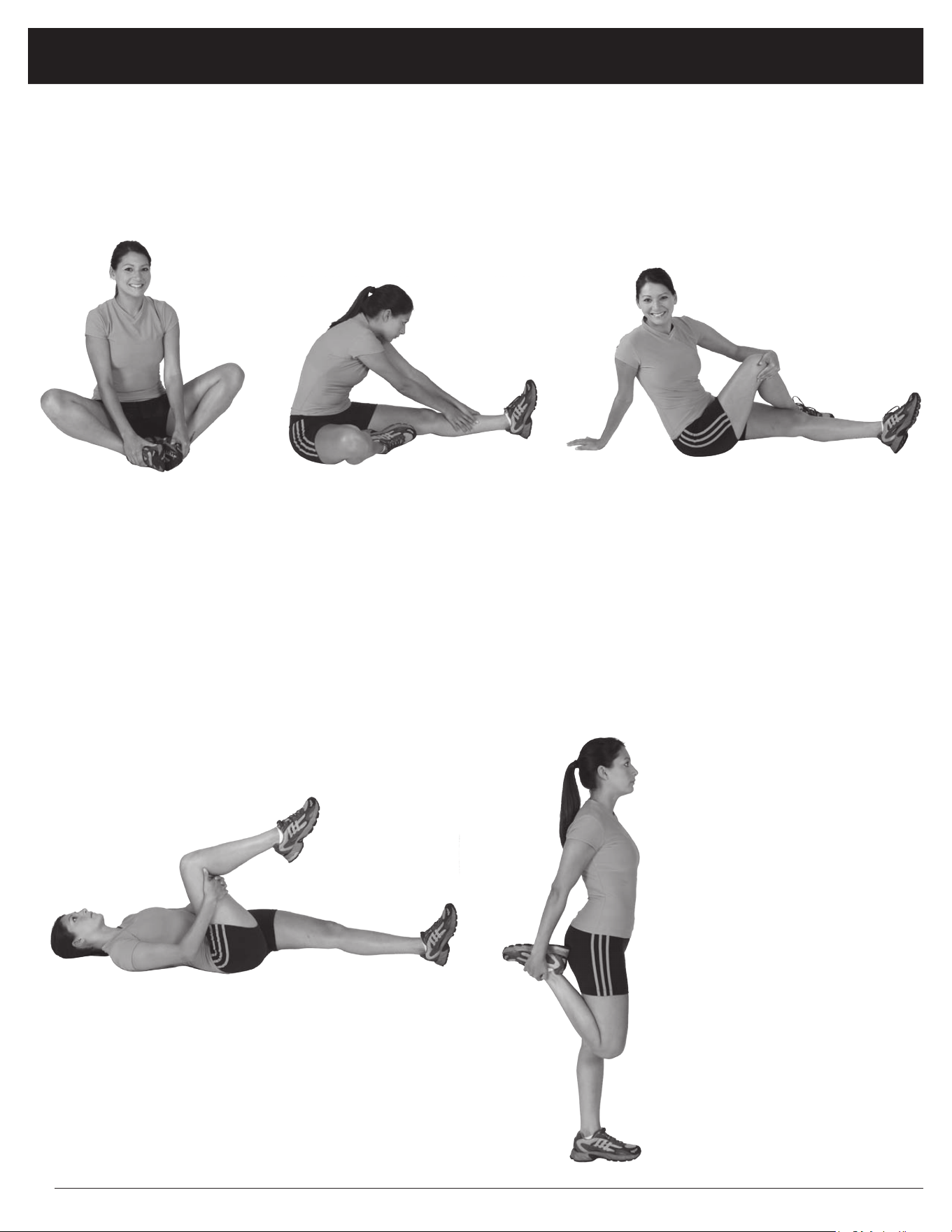
Warm-Up Instructions
Groin Stretch
1. Sit with your knees flexed
and soles of feet together.
2. Hold your ankles and bend
at your hips (keep your
back straight) as you press
your knees toward the
floor with your elbows.
Hamstring Stretch
1. Sit with your left leg extended and bend your right
leg at the knee as you place the sole of your right foot
against the inner thigh of your extended leg.
2. Flex the foot of your extended leg (toes pointed
toward ceiling) and gently bend forward from your
hips; keep your back straight.
3. Reach your hands on your extended leg as far as pos-
sible and then switch legs and repeat.
Trunk Twister
1. Sit with your leg extended and
bend your right knee as you cross
your right leg over your left leg.
Your right foot should be flat on the
floor alongside your left knee.
2. Place your left arm on the outside
of your right leg and pull against
that leg while twisting your trunk
as far as possible to the right. Place
your right hand on the floor behind
your buttocks. Reverse leg posi-
tions and repeat.
Hip Stretch
1. Lie on your back and raise your right leg as you clasp both hands
under the back of the knee. Keep your left leg straight.
2. Gently pull your right leg toward your trunk without raising your
upper body. Switch leg positions and repeat.
The following flexibility exercises are provided to you as a means to prevent injury while you are exercising. A
proper warm-up routine decreases the chance of injuring your muscles while you are exercising. Please take the
time to do these flexibility exercises before and after each time you exercise.
Quadriceps Stretch
1. Stand on your left leg and hold onto
a support with your left hand.
2. Flex your right leg behind you, grasp
your ankle or foot with your right
hand and pull your foot toward your
buttocks. Keep your back straight
and right knee pointed down. Repeat
on the other leg.
BCB3890 Page 12
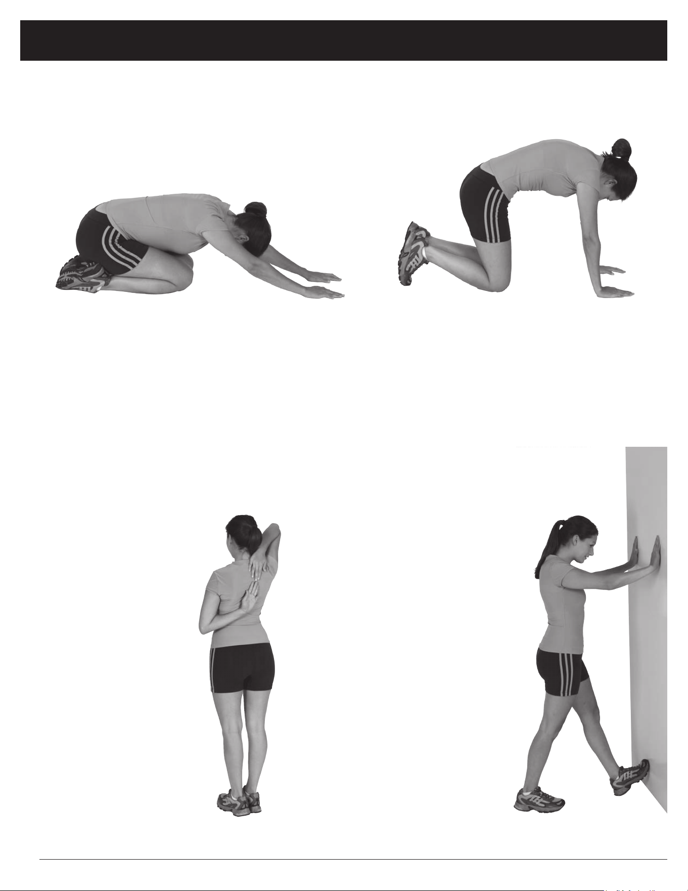
Trunk Flexion, Prone
1. Assume the depicted position on your hands and knees. Stretch your hands out in front of you and then slowly start to pull
them back in toward your body as you tuck your chin and arch your back upward.
2. Return to the starting position slowly.
Shoulder Stretch
1. Bring your right hand over
your right shoulder to the
upper back and bring your
left hand under your left
shoulder to the upper back.
2. Try to reach your finger-
tips. If you are not able to
reach your fingertips, use
a towel as an extension of
your hands and gently pull
one hand toward the other.
Reverse arm positions and
repeat.
Calf Stretch
1. Place both hands against
a wall to aid your balance.
Press the ball of your left foot
against the wall and keep the
heel of the same foot rested
on the floor (make sure your
left knee is bent).
2. Slowly start to straighten your
left knee and you will feel
the muscles in your left calf
stretch. Switch leg positions
and repeat.
Warm-Up Instructions
BCB3890 Page 13
WARNING: SERIOUS INJURIES AND EVEN DEATH CAN OCCUR IF THE PROPER SAFETY PRECAUTIONS ARE NOT FOLLOWED.
The diagram below highlights and reviews many of the important Safety and Warning labels also found
on the unit. Please ensure any user of the unit familiarizes themselves with these Safety and Warning
guidelines before use.
PLEASE KEEP THESE INSTRUCTIONS FOR FUTURE USE & REFERENCE.
DO NOT DISCARD.
1. Thoroughly inspect equipment before each workout. Check all nuts, bolts, screws and pop pins to be in place and fully tightened. Also, if included, check cables for signs
of wear. Replace all worn parts before exercising. Never use the machine if any parts are damaged or missing. Failure to follow these rules may result in serious inj
ury.
2. Keep body, hair and clothing free and clear of all moving parts.
3. Exercise carefully and with caution; you use this product at your own risk. Perform your exercises at a moderate pace; never perform jerky or uncoordinated movement
that may cause injur
y. It is recommended that you should work out with a partner.
4. Do not allow children or minors to play on or around this equipment. Teenagers using strength equipment should be supervised by an adult.
5. Read and understand all instructions & warnings stated in the Owner's Manual as well as on the equipment before exercising.
6. W
ARNING: You should consult your physician before starting any exercise regimen. For your own safety, do not begin any exercise program without proper instruct
ions.
7. The equipment is not to be used in a commerical setting.
8. Replace label if damaged,illegible, or removed.
9.
10. The maximum weight capacity of this unit is 750 pounds (this includes the user's body weight).
• Maximum Olympic Weight Set: 300 lbs
• Maximum Body Weight: 300 lbs
• Maximum Weight on Leg Extension: 150 lbs
This items existed ASTM F2216 standards for fitness equipment.
The use of this exercise equipment involves a
RISK OF PHYSICAL INJURY as well as property damage, which can be minimized by observing the following guidelines:
W A R N I N G !
!
BCB3890 Page 14

Thanks for choosing
BCB 3890
Retailer:
Version:01-13-2014
BCB3890
Made in China
Hupa International Inc.