1
User Manual
PCAL200
Voltage and Current (mA) Source Calibrator
2
4 Safety Information
User should use the calibrator in accordance with the instructions of the manual, or the protective devices provided for the calibrator may be
damaged. The Company is not responsible for any damage caused by failure to follow the safety warning information provided.
“ WARNING” indicates a situation or action that may pose a danger to the user. “Caution” indicates a situation or action that may cause
damage to the calibrator or the equipment being tested. Please refer to Table 1 for an explanation of international electrical symbols used in
the calibrator and the manual.
Table 1. International Electrical Symbols
Grounding
Warning message
WARNING
To avoid electric shock or personal injury:
• Do not apply voltage exceeding the rated voltage indicated on the calibrator between terminals or between any terminal and ground.
• Before use, measure a known voltage to verify that the calibrator is working properly.
• Please follow all safety steps of the instrument.
• Do not use a damaged calibrator. Check the housing of the calibrator for cracks or missing plastic parts before use. Pay special attention to

3
the insulation around the connector.
• Select the proper function and range according to the measurement requirements.
• Make sure that the battery door is securely closed before using the calibrator.
• Remove the test lead from the calibrator before opening the battery door.
• Check the test lead for damage or exposed metal. Check whether the test lead is conductive. Damaged test lead should be replaced before
using the instrument.
• When using the probe, please keep your fingers away from its metal contact. Keep your fingers behind the finger protection device of the
probe.
During wiring, the common wire should be connected first and then the live test lead. During removal, the live test lead should be removed
first.
• Do not use the instrument if it is faulty. Protective devices may have been damaged. If in doubt, please send the instrument for repair.
Do not use the instrument near explosive gases, vapors, or dust.
• The calibrator should be powered by 3 AA LR6 batteries, which should be properly installed in the instrument housing.
• Remove the test lead before switching between different measurement or output functions.
• Use the designated replacement parts when repairing the calibrator.
• To avoid incorrect readings that could result in electric shock or personal injury, the battery should be replaced immediately when the
symbol “ ” appears on the display screen indicating low battery
5 Get to Know the Calibrator
4
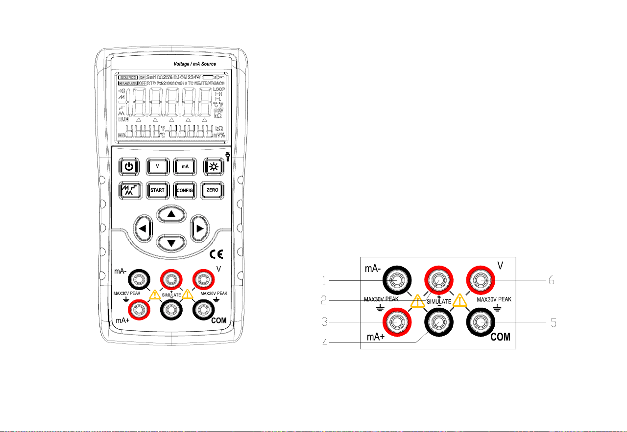
Figure 1. Overall Diagram Figure 2. Output Terminals
5
5.1 Output terminals
Figure 2 shows the input and output terminals of the calibrator.
Table 2 explains their purposes.
2. Output terminals
Terminal
Function description
1
mA-: DCI output (-) terminal
2
SIMULATE output (+) terminal
3
mA+: DCI output (+) terminal
4
SIMULATE output (-) terminal
5
COM: DCV output (-) terminal
6
V: DCV output (+) terminal
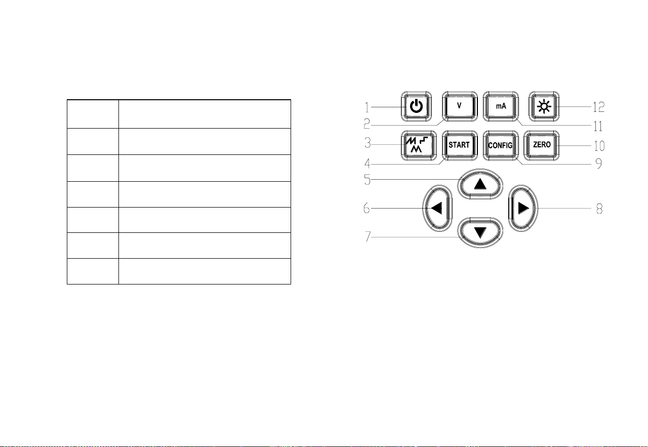
5.2 Buttons
Figure 3 shows the calibrator buttons. Table 3 explains their
functions
Table 3. Button Functions
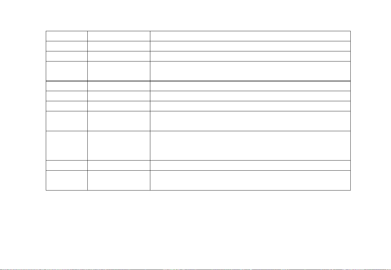
6
Figure 3. Button Functions
S/N
Button name
Description
1
Power button
Power on/off
2
V button
Press this button to switch the function to voltage output
3
Output waveform
switch button
Select output waveform of current output automatic waveform
4
Output START button
Start/stop button for automatic waveform output in the output current function
5, 7
Output setting button
Increase/decrease output setting position
6, 8
Output setting button
Output setting position left/right shift
9
CONFIG button
In the output current function, press this button to enter current-related
parameter settings
10
ZERO button
In the output state, press this button to restore the output value to the default
value. Press this button to save the settings in states of factory maintenance
setting and parameter setting.
11
mA button
Press this button to switch the function to current output
12
Backlight/flashlight
button
Short press to turn on/off the backlight; long press to turn on/off the flashlight
7
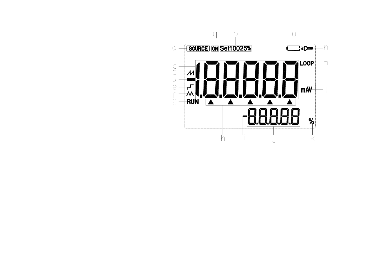
5.3 Display screen
a: Output status mark
b: Main display area for output data
c: Automatic sawtooth wave mode output current mark
d: Output data polarity indicator
e: Auto-stepping mode output current mark
f: Automatic triangular wave mode output current mark
g: Output current automatic waveform operation mark
h: Output setting position indicator
i: Output current percentage data polarity indicator
j: Display of output current percentage data
k: Output current percentage data unit
l: Output function and unit indicator
m: Indicator for 24V power turned on inside the instrument
n: Flashlight on indicator
o: Low battery indicator
p: Output current span mark
q: Output on mark Figure 4. Typical Display Screen

8
6 Preparations
◼ Operating precautions
Safe use for the calibrator
⚫ When using the calibrator for the first time, be sure to read the safety information listed in Section IV.
⚫ Do not open the instrument housing.
To inspect or repair the instrument’s internal components, please contact the seller from whom you purchased the product.
⚫ Fault condition
If the instrument starts to release fume and emit a strange smell, or other abnormal phenomena occur, immediately turn off the
instrument and remove the batteries. Then contact the seller from whom you purchased the instrument.
◼ General operations
⚫ Before moving the calibrator, turn off the power of the tested instrument and then the power of the calibrator. Finally, unplug all test
leads from the calibrator. Use a professional transport packaging box when transporting the calibrator.
⚫ Do not allow any live objects to approach the calibrator in case its internal circuitry gets damaged.
⚫ Do not apply any volatile chemicals to the calibrator housing and operating panel, and do not leave the calibrator attached to any object
made of rubber or vinyl for too long time. Take care to prevent the operating panel, which is made of thermoplastic resin, from
contacting soldering iron, soldering tin or heating objects.
⚫ For safe operations of battery, please refer to the “Install or replace batteries” section.
⚫ Do not use the calibrator without the battery cover installed.
◼ Environmental requirements
Use the instrument under the environmental requirements listed below:
⚫ Ambient temperature and humidity
Ambient temperature: 0-50℃
Ambient humidity: 20%-80%; use the instrument under non-condensing conditions

9
⚫ Use the instrument in a flat and horizontal area
◼ Do not use the instrument in the following environment
⚫ Places directly exposed to sunlight or close to heat sources
⚫ Places close to mechanical vibrations
⚫ Approaching to any interference source, such as high-voltage equipment or engine power
⚫ Approaching to any electromagnetic field or high-density electric power area
⚫ Places filled with large amounts of oil fumes, heat flow, dust or corrosive gases
⚫ Unstable places or places with flammable gases that can cause an explosion
Note:
⚫ If precise measurements or output results are required, use the calibrator under the following environmental requirements:
Ambient temperature range: 23±5℃; ambient humidity range: 20-80% (without condensation)
When using the calibrator in an environment of 0-18℃ or 28-50℃, refer to the Index section and add an additional error value at this
temperature coefficient to achieve the given accuracy.
⚫ When the humidity of the surrounding environment where the instrument is located is less than 30%, use an anti-static pad or take other
effective measures to prevent the generation of static electricity.
⚫ If the instrument needs to be moved from a place with lower ambient temperature or humidity to a place with higher ambient
temperature, or if the instrument is to undergo a sudden temperature change, warm up the instrument for at least one hour under the
ambient temperature before using to ensure its proper operation.
◼ Install or replace batteries
10
WARNING
⚫ To avoid electric shock, the test lead must be removed from the calibrator before opening the battery door. The battery door must be
closed tightly before using the calibrator.
Caution
⚫ To prevent the risk of liquid leakage or battery explosion, install the positive and negative poles of the battery correctly.
⚫ Do not short-circuit the battery.
⚫ Do not disassemble or heat the battery, or throw the battery into a fire.
⚫ When replacing batteries, use 3 identical batteries to replace them simultaneously.
⚫ If the calibrator is not used for a long time, the battery should be removed from the calibrator.
Figure 5

11
Step 1: Before replacing the battery, remove the test lead and turn off the calibrator.
Step 2: Use a slotted screwdriver to rotate the battery door screw by a quarter turn counterclockwise and remove the battery door.
Step 3: Correctly install 3 pieces of AA LR6 alkaline batteries into the battery compartment in the direction as it indicates.
Step 4: After replacing the battery, close the battery door tightly again.
◼ Power on/off
It is necessary to press the power button to turn on the calibrator when the power supply is turned off. Besides, it is needed to press the power
button for 2 seconds to turn off the calibrator when the calibrator is turned on.
◼ Automatic shutdown
In case of no button operations within the default 5 minutes set by the factory, the calibrator automatically shuts down. The automatic
shutdown time can be set in the factory settings. Please refer to Chapter 9 “Factory Settings”.
◼ Turn on/off of backlight
It is necessary to press the backlight button to turn on the backlight, and press it again to turn off the backlight. By doing so, it is easier to
observe the content on the display screen in dark places or at the time of performing output or measurements. When the calibrator operates
with batteries, turning on the backlight will reduce the battery life.
Note
The backlight will automatically turn off after about 60 seconds by default. In case of pressing the backlight button, the backlight will be on
again.
The backlight illumination time can be set in the factory settings. Please refer to Chapter 8 “Factory Settings”.
12
7 Use of output mode
The calibrator should be used for outputting a DC signal.
WARNING
To avoid electric shock, it is not allowed to apply voltage exceeding the rated voltage indicated on the calibrator between the terminals or
between any terminal and ground of the calibrator. The calibrator should be used in situations where the voltage to ground at any terminal
does not exceed a peak value of 30V.
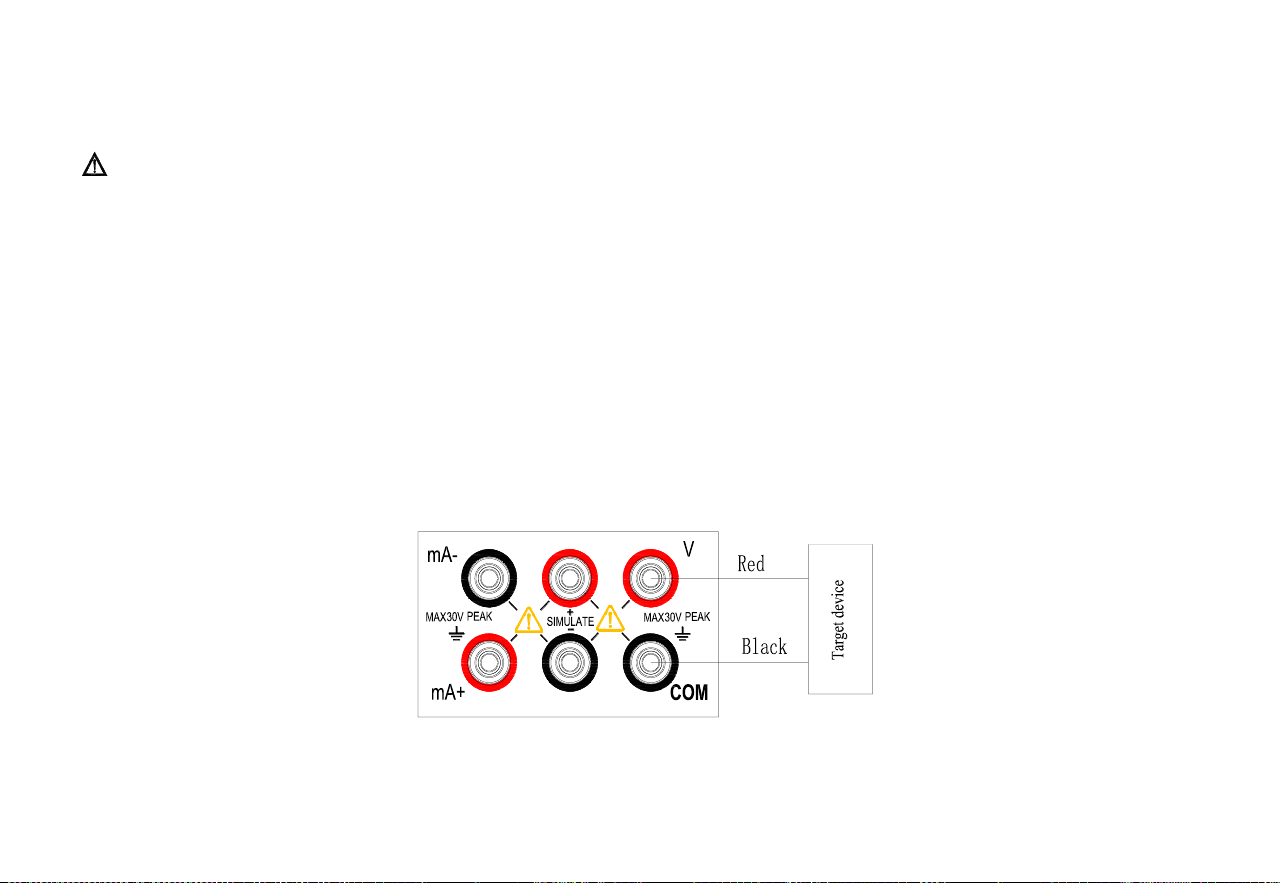
7.1 Output of DC voltage
Step 1: Connect the lead to the target device
⚫ Connect the black lead to the ‘COM’ end and the red lead to the ‘V’ end.
⚫ Connect the other end of the two leads to the signal end of the controlled device and ensure that the terminal polarity is
correct.
Figure 6. Output DC Voltage
13
Step 1: Press 〔V〕 button to switch to the voltage output function and the character ‘V’ on the display screen will light up. At this time,
the DC voltage output function will take into force.
Step 2: Use output setting button to set the output value.
Change the output setting value: 〔〕/〔〕
Change the output digit:〔〕/〔〕
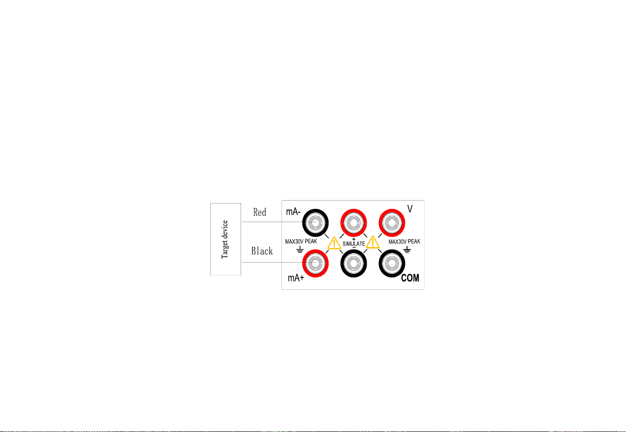
7.2 Output DC current (active)
Step 1: Connect the lead to the target device
⚫ Connect the black lead to the mA-end and the red lead to the ‘mA+’ end.
⚫ Connect the other end of the two leads to the signal end of the controlled device and ensure that the terminal polarity is
correct.
Figure 7. Output DC Current (Active)
Step 2: Press the [mA] key to switch to the current output function. The 'LOOP' and 'mA' characters on the screen light up, indicating
the active DC current output function.
Step 3: Setting of manual stepping span and current output range:
⚫ Press the [CONFIG] key to enter the DC current parameter setting interface. At this time, the character 'MAP.ER' is
displayed in the lower right corner of the screen, indicating manual step span setting; the main display area of the

14
screen shows the parameters to be set;
⚫ Set the required span by pressing the〔〕/〔〕key
Parameter '0' means: When pressing the 〔〕/〔〕key, the corresponding value of the setting bit
increases/decreases by 1;
Parameter '25' means: When pressing the〔〕/〔〕key, the output value increases/decreases by 25% of the
measuring range;
Parameter '100' means: When pressing the〔〕/〔〕key, the output value increases/decreases by 100% of the
measuring range;
Note: When the measuring range is 0-20mA, 25% span means 5mA; when the measuring range is 4-20mA, 25% span
means 4mA.
When the measuring range is 0-20mA, 100% span means 20mA; when the measuring range is 4-20mA, 100% span
means 16mA.
⚫ Press the [ZERO] key to save the settings and automatically switch to the current output range setting interface. At this
time, the character 'SCALE' is displayed in the lower right corner of the screen, indicating the current output range
setting; the main display area of the screen shows the parameters to be set;
⚫ Set the required range by pressing the〔〕/〔〕key: 0-20mA/4-20mA;
⚫ Press the [ZERO] key to save the settings and automatically switch back to span setting.
⚫ Press the [CONFIG] key to exit the setting interface.
Note: After setting the current output range, the set range applies to all current output functions.
Step 4: Set the output value by pressing the output setting key.
⚫ Change the set output value: 〔〕/〔〕;
⚫ Change the set output bit: 〔〕/〔〕, this step is only valid when the span is '0'
⚫

15
7.2.1 Automatic stepping output mode of output current
Step 1: Press 〔 〕 button in the output current function state to switch to the stepping mode function of DC current. At this time, the
symbol on the display screen will light up.
Step 2: Press 〔CONFIG〕 button to enter the DC current step mode parameter setting interface. At this time, the character ‘STEP’ is
displayed in the lower right corner of the display screen, indicating the step size setting. The main display area of the display
screen displays the parameters to be set; Use the 〔〕/〔〕/〔〕/〔〕button to set the required step time (1-200S); Press
the 〔ZERO〕 button to save the settings. Press 〔CONFIG〕 button again to exit the settings interface.
Step 3: Press 〔START〕 button to initiate the automatic stepping of output current and the logo 〔RUN〕 on the display screen will
light up at this time.
Step 4: To end the automatic stepping of output current, press 〔START〕 button to stop the automatic stepping of output current. The
logo 〔RUN〕 on the display screen will go out at this time.
7.2.2 Automatic sawtooth wave output mode of output current
Step 1: Press 〔 〕button in the output current function state to switch to the function of the automatic sawtooth wave mode of DC
current. At this time, the symbol on the display screen will light up.
Step 2: Press 〔CONFIG〕 button to enter the parameter setting interface of the sawtooth wave mode of DC current. At this time, the
character ‘START’ is displayed in the lower right corner of the display screen, indicating the start-point current setting. The
main display area of the display screen displays the parameters to be set; Use the 〔〕/〔〕/〔〕/〔〕 button to set the required
start-point current; Press the 〔ZERO〕 button to save the settings and switch to the next setting item. At this time, the
character ‘STOP’ is displayed in the lower right corner of the display screen, indicating the endpoint current value setting.
The main display area of the display screen displays the parameters to be set; Press the 〔〕/〔〕/〔〕/〔〕 button to
set the required endpoint current; Press 〔ZERO〕 button to save the settings and switch to the next setting item. At this time,
the character ‘CYC’ is displayed in the lower right corner of the display screen, indicating the period setting. The main
display area of the display screen displays the parameters to be set; Press the 〔〕/〔〕/〔〕/〔〕 button to set the required

16
period (5-200S) and press 〔ZERO〕 button to save the settings. Press 〔CONFIG〕 button again to exit the settings interface.
Step 3: Press 〔START〕 button to initiate the automatic stepping of output current and the logo 〔RUN〕 on the display screen will light
up at this time.
Step 4: To end the automatic stepping of output current, press 〔START〕 button to stop the automatic stepping of output current. The
logo 〔RUN〕 on the display screen will go out at this time.
7.2.3 Automatic triangular wave output mode of output current
Step 1: Press 〔 〕button in the output current function state to switch to the function of the automatic sawtooth wave mode of DC
current. At this time, the symbol on the display screen will light up.
Step 2: Press 〔CONFIG〕 button to enter the parameter setting interface of the sawtooth wave mode of DC current. At this time, the
character ‘START’ is displayed in the lower right corner of the display screen, indicating the start-point current setting. The
main display area of the display screen displays the parameters to be set; Use the 〔〕/〔〕/〔〕/〔〕 button to set the
required start-point current; Press the 〔ZERO〕 button to save the settings and switch to the next setting item. At this time,
the character ‘STOP’ is displayed in the lower right corner of the display screen, indicating the endpoint current value setting.
The main display area of the display screen displays the parameters to be set; Press the 〔〕/〔〕/〔〕/〔〕 button to set
the required endpoint current; Press 〔ZERO〕 button to save the settings and switch to the next setting item. At this time, the
character ‘CYC’ is displayed in the lower right corner of the display screen, indicating the period setting. The main display
area of the display screen displays the parameters to be set; Press the 〔〕/〔〕/〔〕/〔〕 button to set the required period
(5-200S) and press 〔ZERO〕 button to save the settings. Press 〔CONFIG〕 button again to exit the settings interface.
Step 3: Press 〔START〕 button to initiate the automatic stepping of output current and the logo 〔RUN〕 on the display screen will light
up at this time.
Step 4: To end the automatic stepping of output current, press 〔START〕 button to stop the automatic stepping of output current. The
logo 〔RUN〕 on the display screen will go out at this time.
17
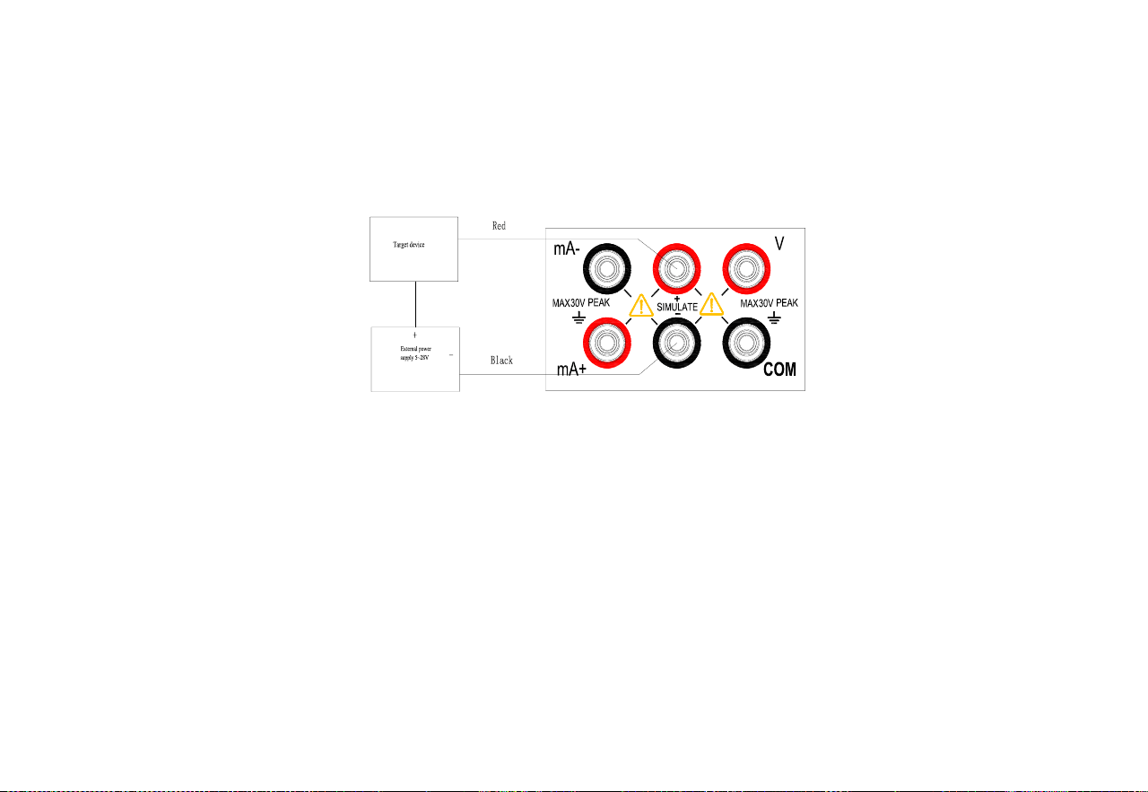
7.3 Output DC current (passive)
Step 1: Connect the lead to the target device
⚫ Connect the black lead to the SIMULATE - end and the red lead to the SIMULATE + end.
⚫ Connect the other end of the two leads to the input end of the controlled device and ensure that the terminal polarity is
correct.
Figure 8. Output DC Current (Passive)
Step 2: Press 〔mA〕 button to switch to the current output function and the character ‘mA’ on the display screen will light up. At this
time, the passive DC current output function will take into force.
Please refer to the active DC current function for other operations.
Tip: Passive DC current requires an external 5-28V DC power supply.

18
8. Factory settings
The calibrator can be used for changing the default factory settings.
To enter: Press and hold the Backlight button, and then press the Power button to turn on the instrument. After the instrument
enters the settings interface, release the Backlight button.
8.1 Automatic shutdown time setting
Step 1: After entering the settings interface, you will find “APOF” shown on the display screen, which indicates the automatic
shutdown setting.
Step 2: Use the setting buttons 〔〕/〔〕/〔〕/〔〕 to set the required parameters. The display unit of automatic shutdown time
is minute.
Setting range: 0-60 minutes; 0 represents cancelling the automatic shutdown, while other values represent the corresponding
time after which the instrument will shut down
Step 3: Press 〔ZERO〕 button. The display screen will show “SAVE”, indicating that the setting has been saved.
8.2 Backlight time setting
Step 1: Press〔V〕button to make the display screen show “BLOF”, which indicates the backlight time setting.
Step 2: Use 〔〕/〔〕/〔〕/〔〕 to set the required parameters. The display unit of backlight time is second.
Setting range: 0-3600 seconds; 0 represents cancelling the automatic backlight shutdown and other values represent the
corresponding time after which the instrument backlight will shut down.
Step 3: Press 〔ZERO〕 button. The display screen will show “SAVE”, indicating that the setting has been saved.

19
8.3 Flashlight time setting
Step 1: Press 〔V〕 button to make the display screen show “LTOF”, which indicates the flashlight time setting.
Step 2: Use 〔〕/〔〕/〔〕/〔〕to set the required parameters. The display unit of flashlight time is minute.
Setting range: 0-30 minutes; 0 represents cancelling the automatic backlight shutdown and other values represent the
corresponding time after which the instrument backlight will shut down.
Step 3: Press 〔ZERO〕 button. The display screen will show “SAVE”, indicating that the setting has been saved.
8.4 Factory default setting
Step 1: Press 〔V〕 button to make the display screen show “FACT”, which indicates the factory default setting.
Step 2: Use 〔〕/〔〕to set the required parameters;
NO indicates that all settings are not restored to factory parameters, while YES indicates that all settings are restored to
factory parameters.
Step 2: Press 〔ZERO〕 button. The display screen will show “SAVE”, indicating that the setting has been saved.
All settings of the factory parameters are as follows:
APOF: 5 minutes.
BLOF: 60 seconds.
LTOF: 5 minutes.
Tip: Whenever you change the setting of any item, there is a need to press 〔ZERO〕 button to save the set value. Any press of the
〔ZERO〕 button will only save the latest set value.
20
9 Replace the battery or fuse
WARNING
To avoid electric shock, the test conductor must be removed from the calibrator before opening the battery door. The battery door must
be closed tightly before using the calibrator.
Caution
◼ To prevent the risk of liquid leakage or battery explosion, install the
battery correctly. Positive and negative polarity
◼ Do not short-circuit the battery.
◼ Do not disassemble or heat the battery, or throw the battery into a
fire.
◼ When replacing batteries, use 3 identical batteries to replace them
simultaneously.
◼ If the calibrator is not used for a long time, the battery should be
removed from the calibrator.
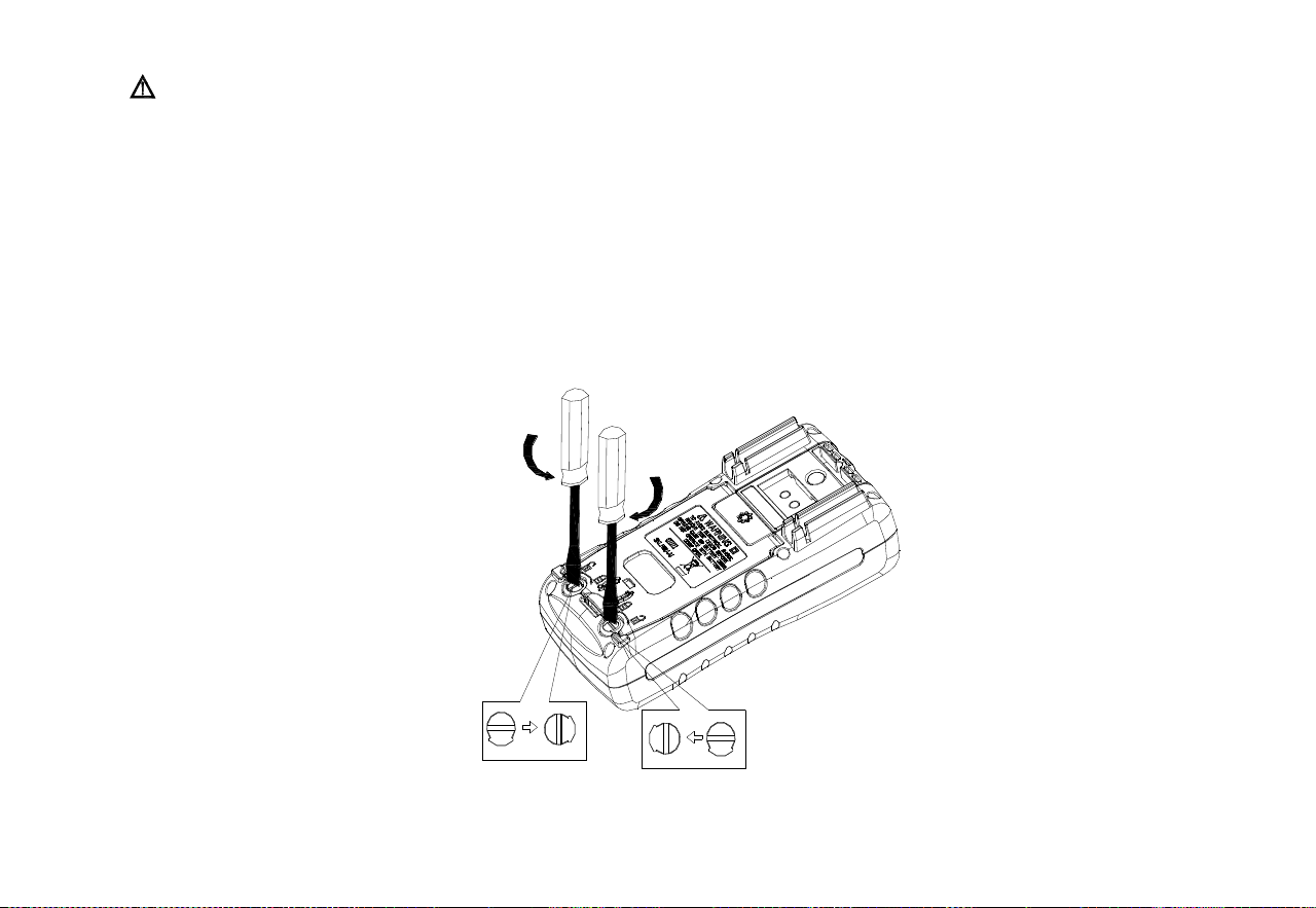
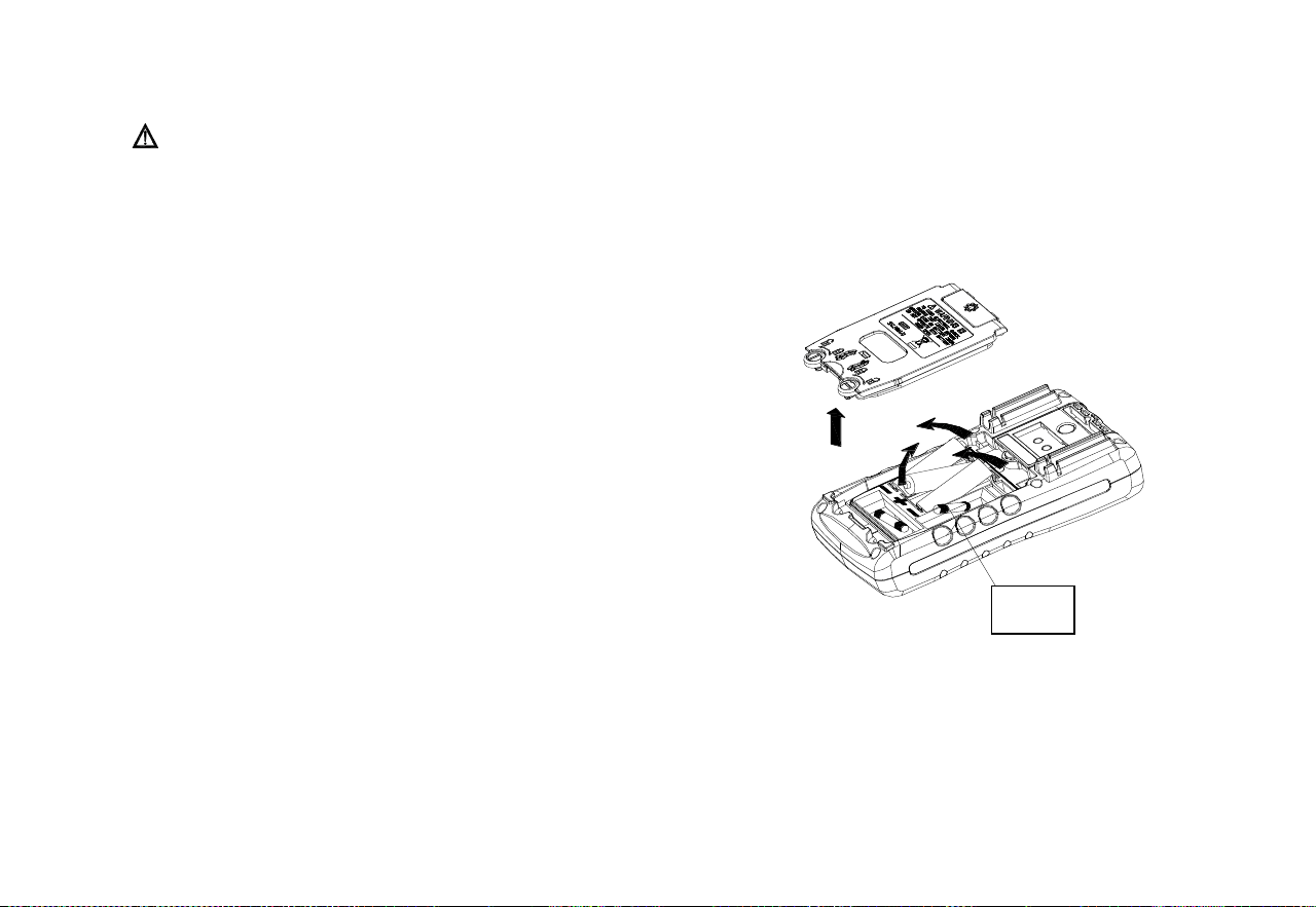
Step 1: Before replacing the battery or fuse, remove the test leads and the
charger and turn off the calibrator.
Step 2: Use a slotted screwdriver to rotate the battery door screw by a
quarter turn counterclockwise and remove the battery door, as shown in Figure 9.
Figure 9. Replacement of Battery and Fuse
Step 3: Correctly install 3 same AA LR6 batteries into the battery compartment in the direction as it indicates. Or replace the same
model of fuse (100mA/250V).
Step 4: After replacing the batteries, close the battery door and fasten the screw fastener tightly again.
Fuse

21
10 Maintenance
10.1 Cleaning of calibrator
WARNING
Designated replacement parts should be used to avoid personal injury or damage to the calibrator. Do not allow water to enter the
housing.
Caution
Do not use solvent or abrasive cleaner to avoid damage to the plastic lens and housing. Clean the calibrator with a soft cloth dampened
with a little water or mild soapy water.
10.2 Service center for calibration or repair
Calibration, repair or maintenance of the instrument should only be carried out by experienced maintainer. Check the battery first if the
calibrator is faulty, and replace it if necessary.
Make sure that the calibrator is operated in line with the instructions in this manual. If there is a malfunction with the calibrator, please
send it back accompanied by a fault description. If you still keep the original packing box, please send the calibrator to your nearest
service center with strong packing (please pay for postage and insurance). The Company does not assume responsibility for any
damage caused by transportation.
Calibrators guaranteed by the Company can be repaired or replaced quickly (at the Company’s discretion) and sent back free of charge.
Please refer to the guarantee clause in this manual. If the warranty period has expired, there will be a certain fee for repairing the
calibrator. If the calibrator is not included in the guarantee item, please contact an authorized service center of the Company to inquire
about repairs and fees. To find an authorized service center, please refer to the section “Contact Us” at the front of the manual.

22
11 Index
Analog output function [Used within one year after calibration, 23℃±5℃, 20~70% RH, accuracy = ± (% set value + reading)]
Output
function
Measurement
range
Output range
Resolution
Accuracy
Remarks
DC voltage
DCV
10V
-1.000V~11.000V
0.001V
0.05%+2mV
Maximum output current of 5mA
DC current
DCI
30mA
0.000mA~30.000mA
0.001mA
0.05%+4uA
At 20 mA, a maximum load of 1000Ω
resistance
At the time of simulating the
transmitter, the external circuit power
supply is 5~28V
Other characteristics:
⚫ Uncertainty includes standard uncertainty, hysteresis, nonlinearity, repeatability, and typical long-term stability over the
period mentioned (K = 2).
⚫ Maximum applied voltage at output terminal: approximately 30Vpk; Maximum applied current at output terminal:
approximately 25mA
⚫ Load characteristics: capacitive load ≥0.01uF; Inductive load ≥ 0.01uF 100uH;Output load affects DCV (0.001% full scale
+ 1nV)/ mA
⚫ Temperature coefficient: 0.1 × Basic accuracy/℃ (temperature range<18℃ or >28℃)
23