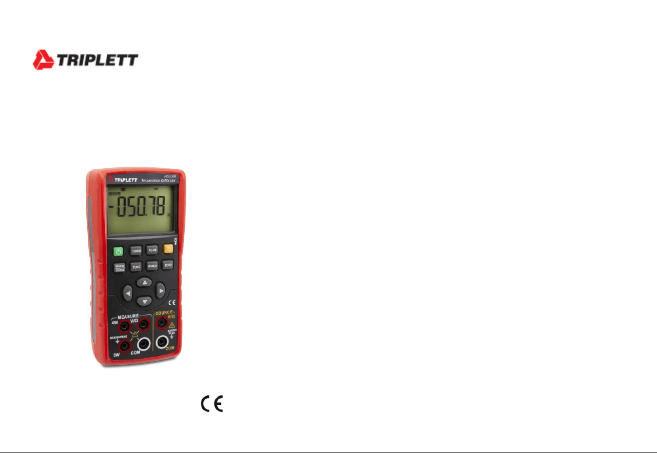
1
User Manual
PCAL100
Temperature Calibrator
2
1 Safety Information
User should use the calibrator in accordance with the instructions of the manual, or the protective measures provided by the calibrator may be
damaged. The Company is not responsible for any damage caused by failure to follow the safety warning information provided.
“ WARNING” indicates a situation or action that may pose a danger to the user. “Caution” indicates a situation or action that may
cause damage to the calibrator or the equipment being tested. Please refer to Table 1 for an explanation of international electrical symbols
used in the calibrator and the manual.
Table 1. International electrical symbols
Grounding
Warning message
WARNING
To avoid electric shock or personal injury:
• Do not apply voltage exceeding the rated voltage indicated on the calibrator between terminals or between any terminal and ground.
• Before use, measure a known voltage to verify that the calibrator is working properly.

3
• Please follow all safety steps of the instrument.
• Do not use a damaged calibrator. Check the housing of the calibrator for cracks or missing plastic parts before use. Pay special attention to
the insulation around the connector.
• Select the proper function and range according to the measurement requirements.
• Make sure that the battery door is securely closed before using the calibrator.
• Remove the test lead from the calibrator before opening the battery door.
• Check the test lead for damage or exposed metal, and if it is conductive. Damaged test lead should be replaced before using the instrument.
• When using the probe, please keep your fingers away from its metal contact and behind the finger protection device of the probe.
• When wiring, the common wire should be connected first and then the live test lead. During removal, the live test lead should be removed
first.
• Do not use the instrument if it is malfunctioning, since protective measures may have been damaged. If in doubt, please send the instrument
for repair.
• Do not use the instrument near explosive gases, vapors, or dust.
• The calibrator should be powered by 3 AA LR6 batteries, which should be properly installed in the instrument housing.
• Remove the test lead before switching between different measurement or output functions.
• Use the designated replacement parts when repairing the calibrator.
• To avoid incorrect readings that could result in electric shock or personal injury, the battery should be replaced immediately when the
symbol “ ” appears on the display screen indicating low battery
4
2 Get to Know the Calibrator
5
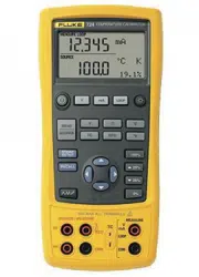
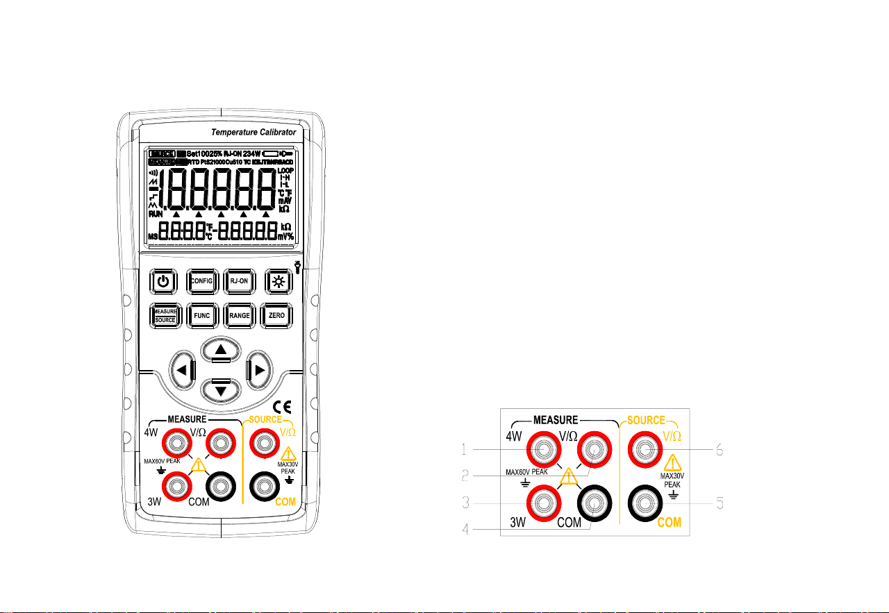
Figure 1. Overall diagram Figure 2. Input/output terminals
2.1 Input and output terminals 5.2 Buttons
Figure 2 shows the input and output terminals of the calibrator. Table 2 explains their purposes.
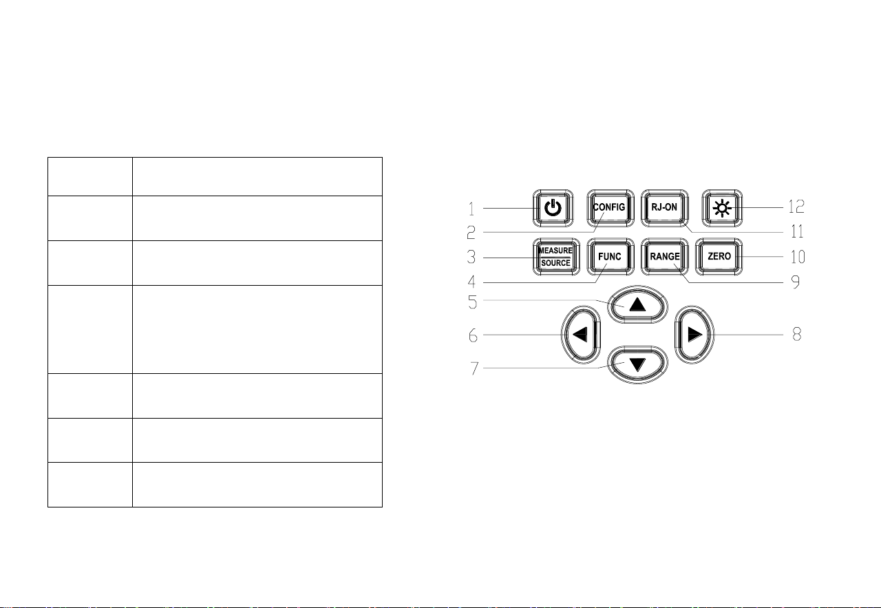
Figure 3 shows the calibrator buttons. Table 3 explains their functions.
2. Input/output terminals
Terminal
Function description
1
4W terminal: 4-wire resistance
measurement high-end SENSE
2
V Ω terminal: Input terminal for all
measurement (+)
3
3W terminal: 4-wire resistance
measurement low-end SENSE
3-wire resistance measurement
SENSE terminal
4
COM terminal: Common (-)(return)
terminal for all inputs
5
COM terminal: Common (-)(return)
terminal for all outputs
6
V Ω terminal: Output terminal for all
outputs(+)
Figure 3. Button functions
6
Table 3. Button functions
SN
Button name
Description
1
Power button
Power on/off
2
CONFIG button
Configuration button: Set the wire system when inputting resistance; Set the
excitation when outputting resistance; Set the compensation in TC function
3
MEASURE/SOURCE
button
Input/output state switching
4
FUNC button
Input/output function switching
5,7
Output setting button
Output setting position increases/decreases
6,8
Output setting button
Output setting position shifts left/right
8
Output ZERO button
Reset the output value to the default value. Press this button to save the setting
in factory maintenance setting function.
9
RANGE button
Select input/output range
10
ZERO button
Reset the output value to the default value. Press this button to save the setting
in factory maintenance and configuration setting function.
11
RJ-ON button
Temperature compensation on/off
12
Backlight/flashlight
button
Short press to turn on/off the backlight; long press to turn on/off the flashlight
7
5.3 Display screen
a: Mark for instrument output working mode
b: Mark for instrument measurement working mode
c: On/off function mark
d: Input/output value polarity mark
e: Input/output value
f: Output bit indicator
g: Cold-end compensation temperature value
h: Cold-end compensation temperature unit
i: Voltage/resistance value corresponding to
thermocouple/thermal resistance function
j: Voltage/resistance unit corresponding to
thermocouple/thermal resistance function
k: Input/output value unit mark
l: Output resistance excitation mark
m: Thermocouple function mark
n: Thermocouple range indicator
o: Flashlight mark
p: Battery status symbol
q: Input resistance/thermal resistance wire system mark Figure 4. Typical display screen
r: Mark for thermocouple cold-end compensation on
s: Thermal resistance range indicator
t: Thermal resistance function mark
u: Signal connection mark

8
6 Preparations
◼ Operating precautions
Safe use for the calibrator
⚫ When using the calibrator for the first time, be sure to read the safety information listed in Section IV.
⚫ Do not open the instrument housing.
To inspect or repair the instrument’s internal components, please contact the seller from whom you purchased the product.
⚫ Malfunctioning conditions
If the instrument starts to release fume and emit a strange smell, or other abnormal phenomena occur, immediately turn off the
instrument and remove the batteries. Then contact the seller from whom you purchased the instrument.
◼ General operations
⚫ Before moving the calibrator, turn off the power of the tested instrument and then the power of the calibrator. Finally, unplug all test
leads from the calibrator. Use a professional transport packaging box when transporting the calibrator.
⚫ Do not allow any live objects to approach the calibrator in case its internal circuitry gets damaged.
⚫ Do not apply any volatile chemicals to the calibrator housing and operator panel, and do not leave the calibrator attached to any object
made of rubber or vinyl for too long. Take care to prevent the operating panel, which is made of thermoplastic resin, from contacting
soldering iron, soldering tin or heating objects.
⚫ For safe operations of battery, please refer to the “Install or replace batteries” section.
⚫ Do not use the calibrator without the battery cover installed.
◼ Environmental requirements
Use the instrument under the environmental requirements listed below:
⚫ Ambient temperature and humidity
Ambient temperature: 0-50℃

9
Ambient humidity: 20%-80%; use the instrument under non-condensing conditions
⚫ Use the instrument in a flat and horizontal area
◼ Do not use the instrument in the following environment
⚫ Places directly exposed to sunlight or close to heat sources
⚫ Places close to mechanical vibrations
⚫ Approaching to any interference source, such as high-voltage equipment or engine power
⚫ Approaching to any electromagnetic field or high-density electric power area
⚫ Places filled with large amounts of oil fumes, heat flow, dust or corrosive gases
⚫ Unstable places or places with flammable gases that can cause an explosion
Note:
⚫ If precise measurements or output results are required, use the calibrator under the following environmental requirements:
Ambient temperature range: 23±5℃; ambient humidity range: 20-80% (without condensation)
When using the calibrator in an environment of 0-18℃ or 28-50℃, refer to the Index section and add an additional error value at this
temperature coefficient to achieve the given accuracy.
⚫ When the humidity of the surrounding environment where the instrument is located is less than 30%, use an anti-static pad or take other
effective measures to prevent the generation of static electricity.
⚫ If the instrument needs to be moved from a place with lower ambient temperature or humidity to a place with higher ambient
temperature, or if the instrument is to undergo a sudden temperature change, warm up the instrument for at least one hour under the
ambient temperature before using to ensure its proper operation.
◼ Install or replace batteries
10
WARNING
⚫ To avoid electric shock, the test lead must be removed from the calibrator before opening the battery door. The battery door must be
closed tightly before using the calibrator.
Caution
⚫ To prevent the risk of liquid leakage or battery explosion, install the positive and negative poles of the battery correctly.
⚫ Do not short-circuit the battery.
⚫ Do not disassemble or heat the battery, or throw the battery
into a fire.
⚫ When replacing batteries, use 3 identical batteries to replace them
simultaneously.
⚫ If the calibrator will not be used for an extended period of time,
remove the batteries from the calibrator.
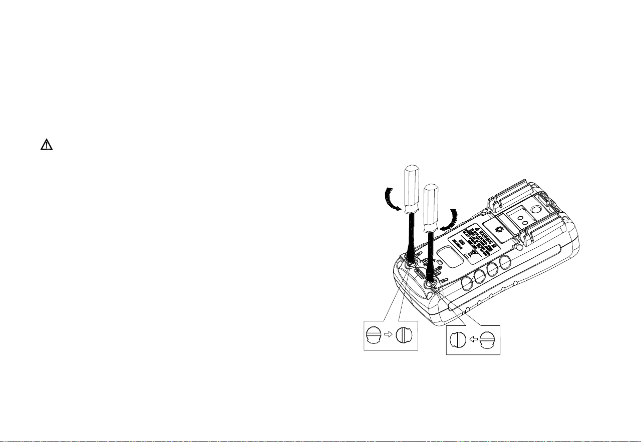
Step 1: Before replacing the battery, remove the test leads and charger,
and turn off the calibrator.
Step 2: Use a slotted screwdriver to rotate the battery door screw by a
quarter turn counterclockwise and remove the battery door.
Step 3: Correctly install 3 AA LR6 alkaline batteries into the battery
compartment in the direction as it indicates.
Step 4: After replacing the batteries, close the battery door tightly again.
Figure 5

11
◼ Power on/off
Press the Power button to turn on the calibrator when the power is off; Press the Power button for 2 seconds to turn off the calibrator when it
is on.
◼ Automatic shutdown
The calibrator automatically shuts down when there is no button operation within the factory default of 5 minutes. The automatic shutdown
time can be set in the factory settings. Please refer to Chapter 9 “Factory Settings”.
◼ Turn backlight on/off
Press the Backlight button to turn the backlight on, and press it again to turn the blacklight off. This makes it easier to see the content on the
display screen in dark places or when performing outputs or measurements. Turning on the backlight will reduce the battery life when the
calibrator is operating on batteries.
Note
The backlight automatically turns off after a default of approximately 60 seconds. Press the Backlight button to re-illuminate backlight.
The backlight illumination time can be set in the factory settings. Please refer to Chapter 9 “Factory Settings”.
12
7 Utilize the Output Mode
Warning
Do not apply voltage exceeding the rated voltage between the terminals of the calibrator or between any terminal and the
ground indicated on the calibrator or use the calibrator in any case where the terminal to ground voltage should not
exceed the peak value of 30V in order to avoid electric shock.
7.1 Connect leads to output terminals
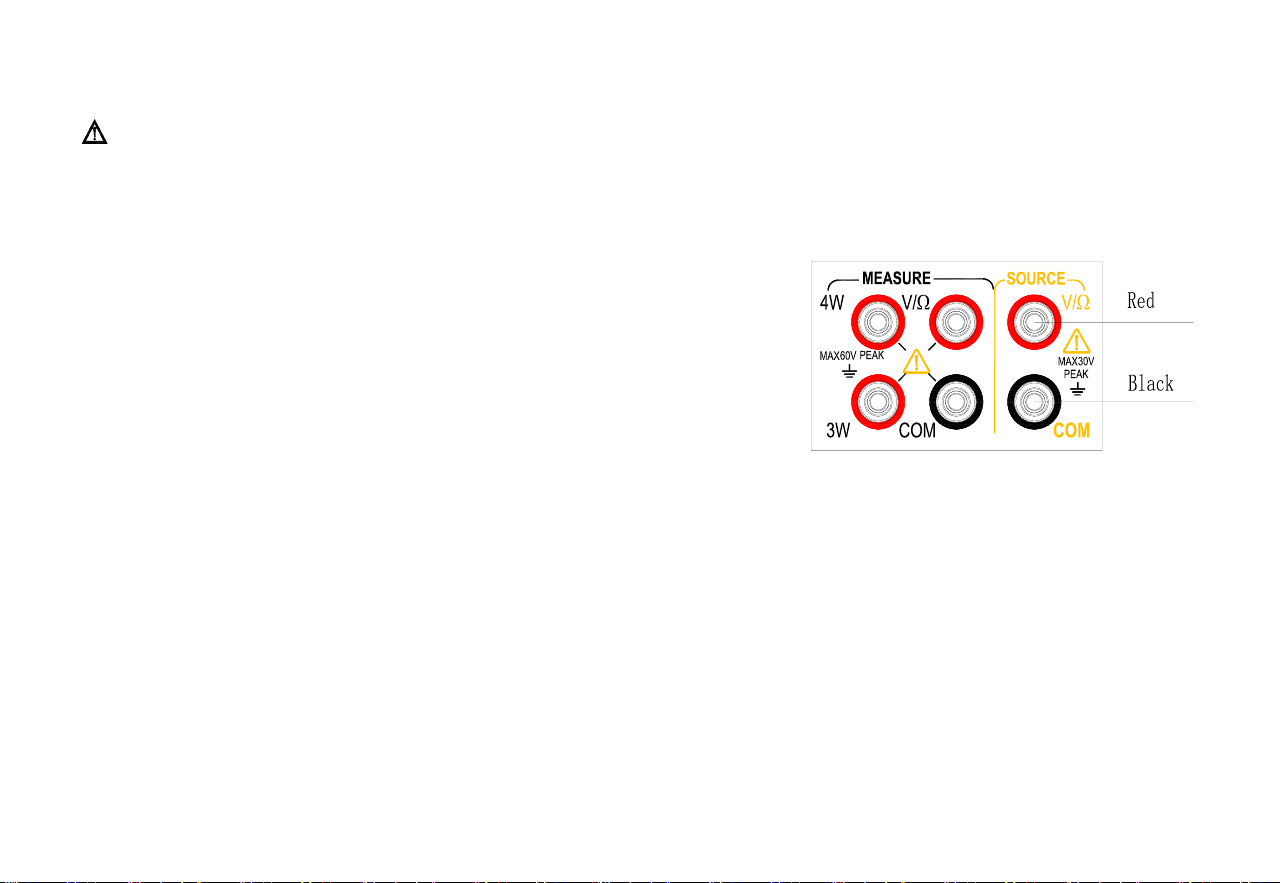
Connection method of all outputs (Figure 6)
Step 1: Connect the black lead to the COM end of the output and the red lead to the
‘V/Ω’end of the output.
Step 2: Connect the other end of the two leads to the input end of the controlled device
and ensure that the terminal polarity is correct.
Figure 6. Output Mode
7.2 Output DC voltage
Step 1: Press〔MEASURE/SOURCE〕button to switch to the output state and〔SOURCE〕sign of the display screen will light up. The
default is DC voltage function with a measurement range of 100mV at this moment. The character mV on the right side of the main
display area of the LCD display screen will light up.
Step 2: Press〔RANGE〕button for choosing proper measurement range (100mV,1V)
Step 3: Use output setting button to set the output value.
Change the output setting bit:〔〕/〔〕
Change the output value:〔〕/〔〕
Tip: The〔ZERO〕button can be pressed to set the output setting to the default initial value (0).

13
7.3 Analog output resistance
Step 1: Press〔FUNC〕button to switch the function to the analog resistance function and the character Ω on the right of the main display
area of the LCD display screen will light up.
Step 2: Press〔RANGE〕button to switch to the required measurement range (400 Ω / 4K Ω).
Measurement range of 400 Ω offers two excitation currents (1mA /0.1mA) that users can manually change according to their
demands for more accurate analog resistance;
Excitation current setting: Press〔CONFIG〕button to enter the excitation current setting interface. The secondary display area at
the lower right corner of the display screen displays OHM.IS at this moment and the characters (I-H stands for 1mA, I-L stands
for 0.1mA) corresponding to the excitation current are displayed in the main display area. Press 〔〕/〔〕 button to change
the excitation and press〔ZERO〕button to save the settings; Press〔CONFIG〕button to exit the settings.
Step 3: Use output setting button to set the output value.
Change the output setting bit:〔〕/〔〕
Change the output value:〔〕/〔〕
Tip: The excitation current prompt on the right side of the main display area will flash if the excitation current does not match and it is
required to enter the setting interface to change the excitation current at this moment in the case of the measurement range of 400 Ω.
7.4 Analog output thermocouple
Step 1: Press〔FUNC〕button to switch to the function of analog couple and the character TC in the upper right corner of the display
screen will light up.
Step 2: Press〔RANGE〕button to switch the required division (R/S/K/E/J/T/N/B/A/C/D).
Step 3: Press〔RJ-ON〕to turn on the cold end compensation function if cold end compensation is required; Skip this step if cold end
compensation is not required.
The cold end compensation method is divided into manual temperature and automatic temperature. The temperature of
automatic temperature is the actual ambient temperature collected by the temperature sensor of the instrument itself. Manual

14
temperature indicates the temperature set by the user.
The method of setting the cold end compensation: Press〔CONFIG〕button to enter the cold end compensation setting
interface and RJST is displayed in the secondary display area at the lower right corner of the display screen at this moment,
indicating the compensation mode setting; The main display area displays the compensation setting parameters (MANU
stands for manual temperature compensation and AUTO stands for automatic temperature compensation) ‘Press〔〕/〔〕
button to change the setting; Press〔ZERO〕button to save the settings and switch to the manual temperature compensation
temperature setting interface and the secondary display area at the lower right corner of the display screen displays RJVA at
this moment. The main display area displays the temperature to be set. The temperature setting range is -10~50 and the
required temperature is set by using 〔〕/〔〕/〔〕/〔〕; Press〔ZERO〕button to save the settings and switch the
settings; Press〔CONFIG〕button to exit the settings.
Tip: For automatic temperature cold compensation method, the lower left corner of the display screen shows the actual
temperature of the current environment; The manual temperature compensation method displays the compensation
temperature set by the user and the M character is lit.
Step 4: Use output setting button to set the output value.
Change the output setting bit:〔〕/〔〕
Change the output value:〔〕/〔〕
7.5 Analog output thermal resistance
Step1: Press〔FUNC〕button to switch the function to the analog thermal resistance output function and the character RTD in the upper
left corner of the display screen will light up.
Step2: Press〔RANGE〕button to switch to the required division(PT100/PT200/PT500/PT1000/Cu50).
PT100 and Cu50 divisions provide two excitation currents (1mA /0.1mA) which can be manually changed by the user
according to demands for more accurate analog thermal resistance;
Excitation current setting: Press〔CONFIG〕button to enter the interface for setting excitation current. OHMI.S is displayed

15
in the secondary display area at the lower right corner of the display screen at this moment and the characters (I-H stands for
1mA and I-L stands for 0.1mA) corresponding to excitation current are displayed in the main display area. Press〔〕/〔〕
button to change the excitation and press〔ZERO〕button to save the settings; Press〔CONFIG〕button to exit the settings.
Step3: Use output setting button to set the output value.
Change the output setting bit:〔〕/〔〕
Change the output value:〔〕/〔〕
Tip: Excitation current prompt on the right side of the main display area will flash if excitation current does not match in the case of the
divisions of PT100 and Cu50. It is required to enter the setting interface to change excitation current at this moment.
7.6 Reset function
⚫ The〔ZERO〕button can be pressed to conduct clearing operation in any measurement range of DC voltage, resistance,
thermocouple, thermal resistance output function to change the output setting value to the default initial value. It is convenient for
users to reset the output value.
8 Utilize the Measurement Mode
Warning
⚫ The measurement function of the calibrator is used where a lead connection is required. The maximum voltage of any input terminal to
ground is 60V peak. Do not apply any voltage above the maximum voltage to the terminal to the ground in order to avoid electric
shock.
Tip
⚫ The “OL” symbol is displayed in the main display area of the display screen when the measured value exceeds the measurement range
of this range.
16
8.1 Connect leads to input terminals
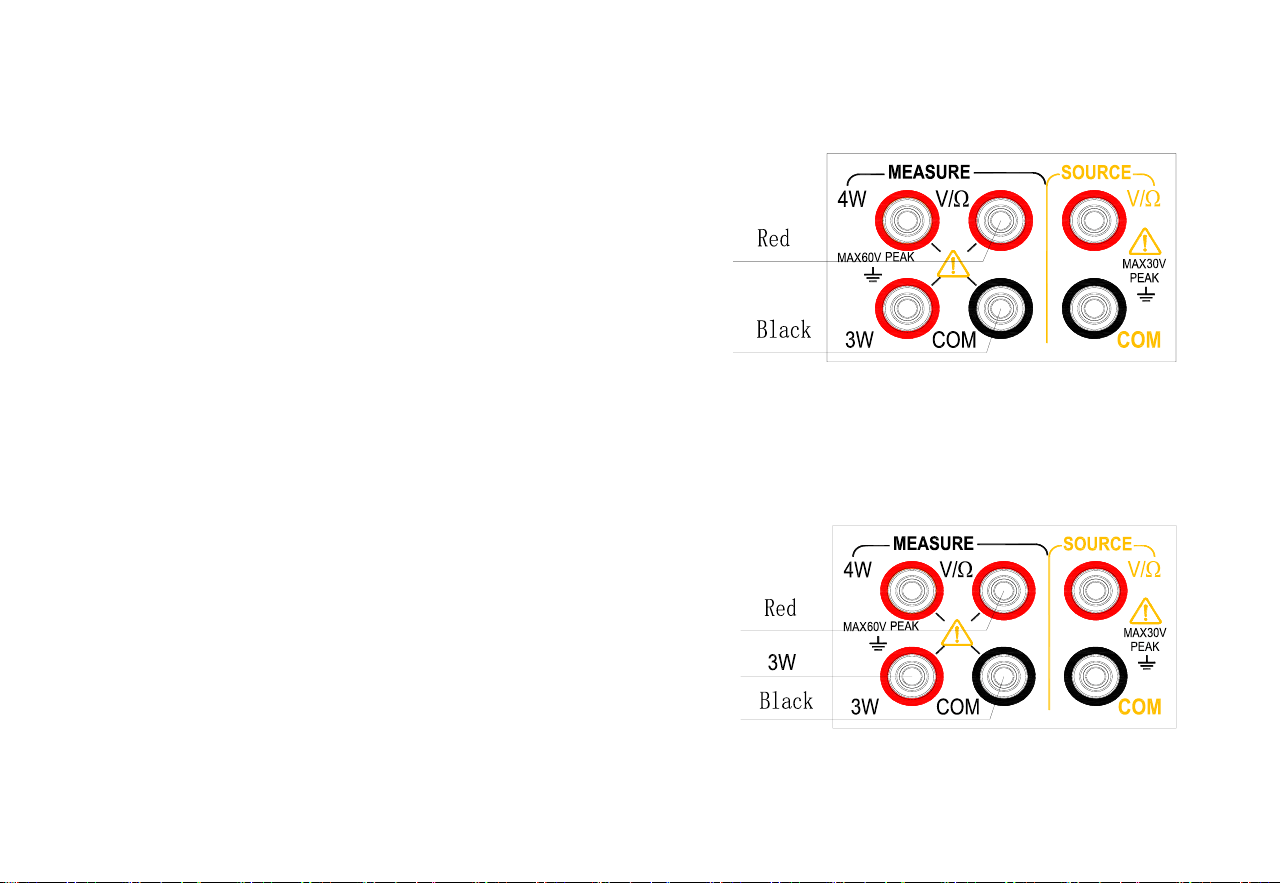
Connection method of DC voltage, thermocouple, thermal resistance, resistance (2W) measurement (Figure 7)
Step1: Connect the black lead to the ‘COM’ end of the input and the
red lead to the ‘VΩ’ end of the input.
Step2: Connect the other end of the two leads to the measurement end
of the device under test and ensure that the terminal polarity is correct.
Figure 7. Measure DC voltage, thermocouple,
thermal resistance and resistance (2W)
Connection method of resistance (3W) and thermal resistance (3W) measurement (Figure 8)
Step 1: Connect the black lead to the ‘COM’ end of the input, the red
lead to the ‘VΩ’ end of the input and the 3W lead to the ‘3W’end.
Step 2: Connect the other end of the three leads to the measurement end
of the device under test respectively and ensure that the terminal polarity
is correct.
Figure 8 Resistance, RTD measurement (3W)
17
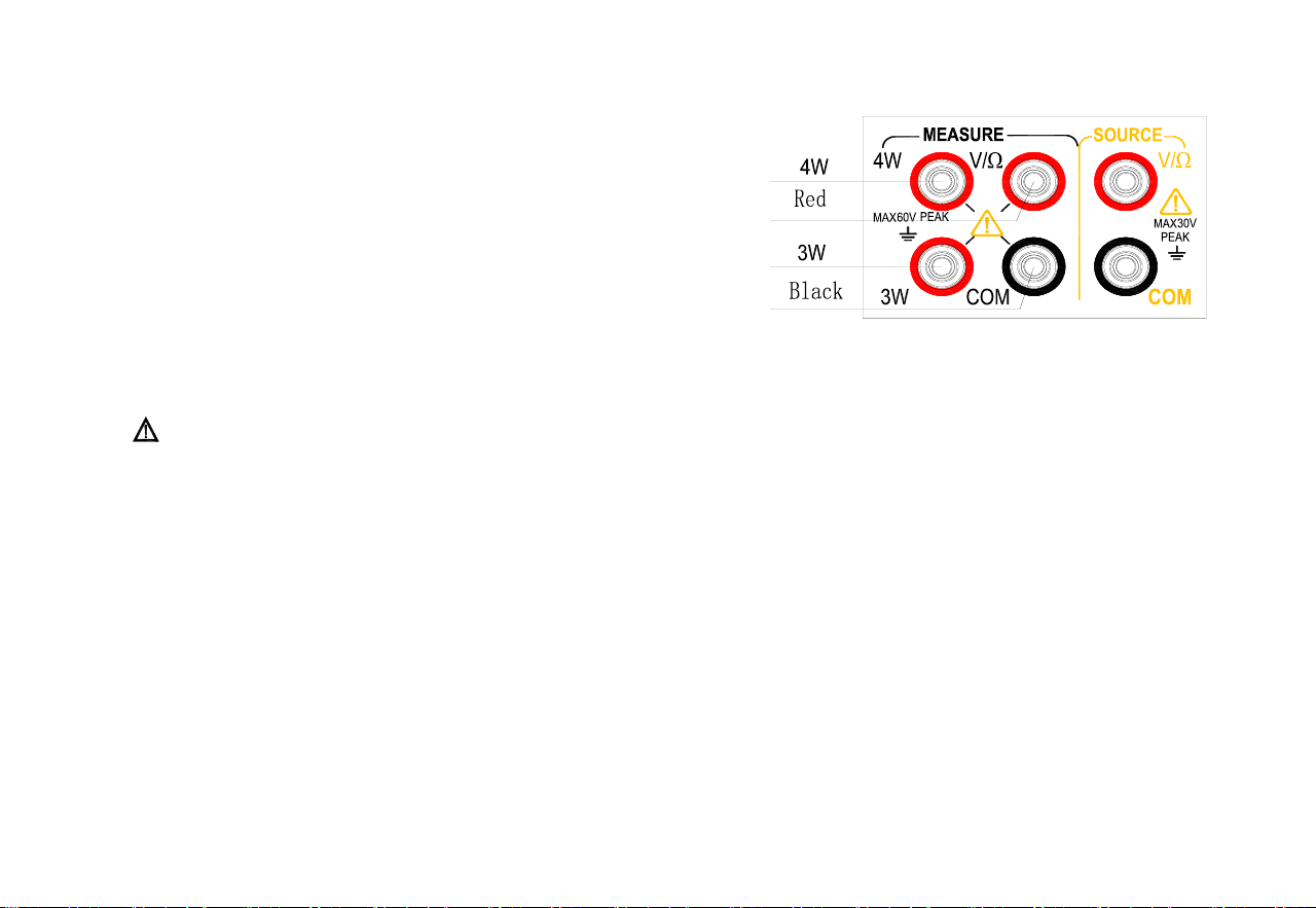
Connection method of resistance (4W) and thermal resistance measurement (4W) (Figure 9)
Step 1: Connect the black lead to the ‘COM’ end of the input, the red lead
to the ‘VΩ’ end of the input, the 3W lead to the ‘3W’ end of the input and
the 4W lead to the ‘4W’ end of the input.
Step 2: Connect the other end of the four leads to the measurement end
of the device under test respectively and ensure that the terminal polarity is
correct.
Figure 9 Resistance, RTD measurement (4W)
Warning
Disconnect the power supply of the device before connecting the calibrator to the device under test.
Incorrect operation of the circuit or during measurement may cause damage to the instrument or injury to people. Therefore,
pay as much attention as possible when performing measurement operations.
8.2 Measurement of DC voltage
Step 1: Ensure the measurement lead is disconnected from the device under test.
Step 2: Press 〔MEASURE/SOURCE〕 button to switch to the measurement state and the 〔MEASURE〕mark on the display screen
will light up. The default is DC voltage function at this moment with a measurement range of 100mV and the mV character
on the right side of the main display area of the LCD display screen will light up.
Step 3: Press〔RANGE〕button to switch to the required range (100mV, 1V, 30V).
Step 4: Connect the measurement lead to the measured end of the device under test and the measurement value is displayed in the main
display area.

18
8.3 Measurement of resistance
Step 1: Ensure the measurement lead is disconnected from the device under test.
Step 2: Press〔FUNC〕button to switch to the resistance function and the Ω character on the display screen will light up.
Step 3: Press〔RANGE〕button to switch the required measurement range (500Ω / 5KΩ).
Step 4: Set the resistance wire system: Press〔CONFIG〕button to enter the wire system setting interface. The secondary display area in
the lower right corner of the display screen displays Wire System at this moment and the wire system (2W/3W/4W) is
displayed in the main display area. Choose the proper wire system using〔〕/〔〕, press〔ZERO〕button to save the setting
and press 〔CONFIG〕button to exit the setting.
Step 5: Connect the measurement lead to the measurement end of the device under test and the measurement value is displayed in the
main display area of the display screen.
8.4 Measurement of thermocouple
Step 1: Ensure the measurement lead is disconnected from the device under test.
Step 2: Press〔FUNC〕button to switch to the thermocouple function and the TC character on the display screen will light up.
Step 3: Press〔RANGE〕button to switch the required divisions (R/S/K/E/J/T/N/B/A/C/D).
Step 4: Press〔RJ-ON〕button to enable the cold end compensation function if cold end compensation is required; Skip this step if cold
end compensation is not required.
The cold end compensation method is divided into manual temperature and automatic temperature. The temperature of
automatic temperature is the actual ambient temperature collected by the temperature sensor of the instrument itself. Manual
temperature indicates the temperature set by the user.
The method of setting cold end compensation: Press〔CONFIG〕button to enter the cold end compensation setting interface.
RJST is displayed in the secondary display area at the lower right corner of the display screen at this time, indicating the
compensation method setting; The main display area displays the compensation setting parameters (MANU stands for
manual temperature compensation and AUTO stands for automatic temperature compensation) ‘Press〔〕/〔〕button to

19
change the setting; Press〔ZERO〕button to save the settings and switch to the manual temperature compensation temperature
setting interface. The secondary display area at the lower right corner of the display screen displays RJVA at this time. The
main display area displays the temperature to be set. The temperature setting range is -10~50 and the required temperature is
set using 〔〕/〔〕/〔〕/〔〕; Press〔ZERO〕 button to save the settings and switch the settings; Press〔CONFIG〕
button to exit the settings.
Tip: For automatic temperature cold compensation method, the lower left corner of the display screen shows the actual
temperature of the current environment; The manual temperature compensation method displays the compensation
temperature set by the user and the M character is lit.
Step 5: Connect the measurement lead to the measurement end of the device under test and the measurement value is displayed in the
main display area of the display screen.
8.5 Measurement of thermal resistance
Step 1: Ensure the measurement lead is disconnected from the device under test.
Step 2: Press〔FUNC〕button to switch to the thermal resistance function and the RTD character of the display screen will light up.
Step 3: Press〔RANGE〕button to switch to required division (PT100 / PT200 / PT500 / PT1000 / Cu50).
Step 4: Set the thermal resistance wire system: Press〔CONFIG〕button to enter the wire system setting interface. WRIE is displayed in
the lower right corner of the display screen at this moment and the wire system (2W/3W/4W) is displayed in the main display
area. Choose the proper wire system using 〔〕/〔〕, press〔ZERO〕button to save the setting and press〔CONFIG〕
button to exit the setting.
Step 5: Connect the measurement lead to the measurement end of the device under test and the measurement value is displayed in the
main display area of the display screen.

20
9 Factory Settings
The calibrator can have changes of the default factory settings.
To enter: Press and hold the Backlight button, and then press the Power button to turn on the instrument. After the instrument
enters the settings interface, release the Backlight button.
9.1 Automatic shutdown time setting
Step 1: After entering the settings interface, you will find “APOF” shown on the display screen, which indicates the automatic
shutdown setting.
Step 2: Use the setting buttons〔〕/〔〕/〔〕/〔〕to set the required parameters. The display unit of automatic shutdown time
is minute.
Setting range: 0-60 minutes; 0 represents canceling the automatic shutdown, while other values represent the corresponding
time after which the instrument will shut down
Step 3: Press〔ZERO〕button, and the display screen will show “SAVE”, indicating that the setting has been saved.
9.2 Backlight time setting
Step 1: Press〔CONFIG〕button to make the display screen show “BLOF”, which indicates the backlight time setting.
Step 2: Use〔〕/〔〕/〔〕/〔〕to set the required parameters. The display unit of backlight time is second.
Setting range: 0-3600 seconds; 0 represents canceling the automatic backlight shutdown, other values represent the
corresponding time after which the instrument backlight will shut down.
Step 3: Press〔ZERO〕button, and the display screen will show “SAVE”, indicating that the setting has been saved.

21
9.3 Flashlight time setting
Step 1: Press〔CONFIG〕button to make the display screen show “LTOF”, which indicates the flashlight time setting.
Step 2: Use〔〕/〔〕/〔〕/〔〕to set the required parameters. The display unit of flashlight time is minute.
Setting range: 0-30 minutes; 0 represents canceling the automatic backlight shutdown, other values represent the
corresponding time after which the instrument backlight will shut down.
Step 3: Press〔ZERO〕button, and the display screen will show “SAVE”, indicating that the setting has been saved.
9.4 Buzzer setting
Step 1: Press〔CONFIG〕button to make the display screen show “BEEP”, which indicates the beep setting.
Use〔〕/〔〕to set the required parameters;
ON indicates that the beep function is on, while OFF indicates that the beep function is off.
Step 3: Press〔ZERO〕button, and the display screen will show “SAVE”, indicating that the setting has been saved.
9.5 Temperature unit setting
Step 1: Press〔CONFIG〕button to make the display screen show “TEPU”, which indicates the temperature unit setting.
Step 2: Use〔〕/〔〕to set the required parameters;
C indicates that the temperature unit is Celsius, while F indicates that the temperature unit is Fahrenheit.
Step 3: Press〔ZERO〕button, and the display screen will show “SAVE”, indicating that the setting has been saved.

22
9.6 Factory default setting
Step 1: Press〔CONFIG〕button to make the display screen show “FACT”, which indicates the factory default setting.
Step 2: Use〔〕/〔〕to set the required parameters;
NO indicates that all settings are not restored to factory parameters, while YES indicates that all settings are restored to
factory parameters.
Step 2: Press〔ZERO〕button, and the display screen will show “SAVE”, indicating that the setting has been saved.
All settings of the factory parameters are as follows:
APOF: 5 minutes.
BLOF: 60 seconds.
LTOF: 5 minutes.
BEEP: ON
TEPU: C
Tip: Whenever you change the setting of any item, there is a need to press〔ZERO〕button to save the set value. Any press of the〔ZERO〕
button will only save the latest set value.
23
10 Replace the Battery
WARNING
To avoid electric shock, the test lead must be removed from the calibrator before opening the battery door. The battery door must be
closed tightly before using the calibrator.
Caution
◼ To prevent the risk of liquid leakage or battery explosion, install the positive and negative poles of the battery correctly.
◼ Do not short-circuit the battery.
◼ Do not disassemble or heat the battery, or throw the battery into a
fire.
◼ When replacing batteries, use 3 identical batteries to replace them
simultaneously.
◼ If the calibrator will not be used for an extended period of time,
remove the batteries from the calibrator
Step 1: Before replacing the battery, remove the test leads and turn off the
calibrator.
Step 2: Use a slotted screwdriver to rotate the battery door screw by a
quarter turn counterclockwise and remove the battery door, as
shown in Figure 10.
Step 3: Correctly install 3 same AA LR6 batteries into the battery
compartment in the direction as it indicates
Step 4: After replacing the batteries, close the battery door and fasten the
screw tightly again.
Figure 10. Replace the battery

24
11 Maintenance
11.1 Clean the calibrator
WARNING
Designated replacement parts should be used to avoid personal injury or damage to the calibrator. Do not allow water to enter the
housing.
Caution
Do not use solvent or abrasive cleaner to avoid damage to the plastic lens and housing. Clean the calibrator with a soft cloth dampened
with a little water or mild soapy water.
11.2 Service center for calibration or repair
Calibration, repair or maintenance of the instrument should only be carried out by experienced maintainer. Check the battery first if the
calibrator is malfunctioning, and replace it if necessary.
Make sure that the calibrator is operated in line with the instructions in this manual. If there is a malfunction with the calibrator, please
send it back accompanied by a fault description. If you still keep the original packing box, please send the calibrator to your nearest
service center with strong packing (please pay for postage and insurance). The Company does not assume responsibility for any
damage caused by transportation.
Calibrators guaranteed by the Company can be repaired or replaced quickly (at our Company’s discretion) and sent back free of charge.
Please refer to the guarantee clause in this manual. If the warranty period has expired, there will be a certain fee for repairing the
calibrator. If the calibrator is not included in the guarantee item, please contact an authorized service center of the Company to inquire
about repairs and fees. To find an authorized service center, please refer to the section “Contact Us” at the front of the manual.
25
12 Index
Input measurement function [Used within one year after calibration, 23℃±5℃, 20-70% RH, accuracy = ± (% set
value + reading)]
Measurement
function
Range
Measurement range
Resolution
Accuracy
Remarks
DC voltage
DCV
100mV
-110.000mV~110.000mV
0.01mV
0.05%+0.03mV
Input resistance:
approximately 1MΩ
1V
-1.1000V~1.1000V
0.0001V
0.05%+0.3mV
30V
-30.000V~30.000V
0.001V
0.02%+2mV
Resistance
OHM
500Ω
0~550.00Ω
0.01Ω
0.05%+0.2Ω
2W/3W/4W measurement
500Ω approximately 1mA
excitation
5KΩ approximately 0.1mA
excitation
Open circuit voltage:
approximately 2.5V
The accuracy does not
include lead resistance
5KΩ
0~5.5000KΩ
0.0001KΩ
0.05%+2Ω

26
Thermocouple
TC
R
0C~1767C
1C
0.05%+3℃(less
than or equals
to
100C)
0.05%+2℃(more
than
100C)
Use ITS-90 temperature
scale
The accuracy does not
include the error of
cold-end compensation
The accuracy does not
include sensor inaccuracy
The accuracy does not
include the influence of
thermoelectric potential
The materials
corresponding to the
calibrations on the left
are as follows:
R: Platinum Rhodium 13-
Platinum
S: Platinum Rhodium 10-
Platinum
K: Nickel chromium -
nickel silicon
E: Nickel chromium -
S
0C~1767C
K
-100.0~1372.0C
0.1C
0.05%+2℃(less
than or equals
to
-100C)
0.05%+1℃(more
than
-100C)
E
-50.0C~1000.0C
J
-60.0C~1200.0C
T
-100.0C~400.0C

27
N
-200.0~1300.0C
copper nickel
(constantan)
J: Iron - copper nickel
(constantan)
T: Copper - copper nickel
(constantan)
N: Nickel chromium
silicon - nickel silicon
B: Platinum Rhodium 30 -
Platinum
A: Tungsten rhenium 5-
Tungsten rhenium 20
C: Tungsten rhenium 5-
Tungsten rhenium 26
D: Tungsten rhenium 3-
Tungsten rhenium 25
B
600C~1820C
1C
0.05%+3℃
A
0C~2500C
1C
C
0C~2310C
1C
D
0C~2310C
1C
Thermal
resistance
RTD
Pt100
385
-200.0C~800.0C
0.1C
0.05%+0.6℃
Use Pt (385) temperature
scale

28
(3W)
Pt200
385
-200.0C~630.0C
2W/3W/4W measurement
500Ω approximately 1mA
excitation
5KΩ approximately 0.1mA
excitation
Open circuit voltage:
approximately 2.5V
The accuracy does not
include the error caused
by the mismatch of the 2
W/3 W measurement lead
resistance
The accuracy does not
include sensor inaccuracy
The accuracy does not
include the influence of
thermoelectric potential
Pt500
385
-200.0C~630.0C
Pt1000
385
-200.0C~630.0C
Cu50
-50.0C~150.0C
On/off
detection
500Ω
≤50Ω sounding
0.01Ω
Approximately 1mA
excitation

29
Other characteristics:
⚫ Uncertainty includes standard uncertainty, hysteresis, nonlinearity, repeatability, and typical long-term stability over the
period mentioned (K = 2).
⚫ Display refresh rate: 2-3 times / second.
⚫ Maximum applied voltage at input terminal: 60 Vpk.
⚫ Input common-mode rejection: 50Hz /60 Hz > 80 db; Input serial-mode rejection: 50Hz /60 Hz > 40 db
⚫ Temperature coefficient: 0.1 × basic accuracy / ℃ (temperature range <18℃ or >28℃)

30
Analog output function [Used within one year after calibration, 23℃±5℃, 20-70% RH, accuracy = ± (% set value
+ reading)]
Output
function
Range
Output range
Resolution
Accuracy
Remarks
DC voltage
DCV
100mV
-10.000mV~110.00mV
0.01mV
0.05%+0.03mV
Maximum output current: 0.5mA
1V
-0.1000V~1.1000V
0.0001V
0.05%+0.3mV
Maximum output current 2mA
Ohm
OHM
400Ω
0~400.0Ω
0.1Ω
0.05%+0.2Ω
The excitation current is
±0.1 - ±5mA
Maximum output voltage 2V
When the excitation current
is ±0.1 - 0.5mA, additional
error of 0.3Ω is added
The accuracy does not include
lead resistance
4KΩ
0~4.000KΩ
1Ω
0.05%+2Ω
Thermocouple
TC
R
0C~1767C
1C
0.05%+3(less
than or equals
to
Use ITS-90 temperature scale
The accuracy does not include
the error of cold-end

31
S
0C~1767C
100C)
0.05%+2(more
than
100C)
compensation
The accuracy does not include
sensor inaccuracy
The accuracy does not include
the influence of
thermoelectric potential
The materials corresponding
to the calibrations on the
left are as follows:
R: Platinum Rhodium 13-
Platinum
S: Platinum Rhodium 10-
Platinum
K: Nickel chromium - nickel
silicon
E: Nickel chromium - copper
nickel (constantan)
J: Iron - copper nickel
(constantan)
T: Copper - copper nickel
(constantan)
K
-200.0C~1372.0C
0.1C
0.05%+20(less
than or equals
to
-100C)
0.05%+10(more
than
-100C)
E
-200.0C~1000.0C
J
-200.0C~1200.0C
T
-250.0C~400.0C
N
-200.0C~1300.0C

32
B
600C~1820C
1C
0.05%+3
N: Nickel chromium silicon -
nickel silicon
B: Platinum Rhodium 30 -
Platinum
A: Tungsten rhenium 5-
Tungsten rhenium 20
C: Tungsten rhenium 5-
Tungsten rhenium 26
D: Tungsten rhenium 3-
Tungsten rhenium 25
A
0C~2500C
1C
C
0C~2310C
1C
D
0C~2310C
1C
Thermal
resistance
RTD
Pt100
385
-200.0C~800.0C
0.1C
0.05%+0.6℃
Use Pt (385) temperature
scale
The excitation current is
±0.1 - ±5mA
Maximum output voltage 2V
When the excitation current
is ±0.1 - 0.5mA, additional
Pt200
385
-200.0C~630.0C
Pt500
385
-200.0C~630.0C
33
Pt1000
385
-200.0C~630.0C
error of 0.3Ω is added
The accuracy does not include
lead resistance
The accuracy does not include
the influence of
thermoelectric potential
Cu50
-50.0C~150.0C
Other characteristics:
⚫ Uncertainty includes standard uncertainty, hysteresis, nonlinearity, repeatability, and typical long-term stability over the
period mentioned (K = 2).
⚫ Maximum applied voltage at output terminal: approximately 30Vpk; Maximum applied current at output terminal:
approximately 25mA
⚫ Temperature coefficient: 0.1 × basic accuracy/℃ (temperature range < 18℃ or > 28℃)
34