


AXIS W401 Body W or n Activation Kit
T able of Contents
About the device . . . . . . . . . . . . . . . . . . . . . . . . . . . . . . . . . . . . . . . . . . . . 3
System overview . . . . . . . . . . . . . . . . . . . . . . . . . . . . . . . . . . . . . . . . . . . . . . . . 3
Software requirements . . . . . . . . . . . . . . . . . . . . . . . . . . . . . . . . . . . . . . . . . . . 3
Installation . . . . . . . . . . . . . . . . . . . . . . . . . . . . . . . . . . . . . . . . . . . . . . . . 4
Get started . . . . . . . . . . . . . . . . . . . . . . . . . . . . . . . . . . . . . . . . . . . . . . . . 5
Find the device on the network . . . . . . . . . . . . . . . . . . . . . . . . . . . . . . . . . . . . 5
Open the device's web interface . . . . . . . . . . . . . . . . . . . . . . . . . . . . . . . . . . . . 5
Create an administrator account . . . . . . . . . . . . . . . . . . . . . . . . . . . . . . . . . . . 5
Secure passwords . . . . . . . . . . . . . . . . . . . . . . . . . . . . . . . . . . . . . . . . . . . . . . . 5
V erify that no one has tampered with the device software . . . . . . . . . . . . . . 6
Congure your device . . . . . . . . . . . . . . . . . . . . . . . . . . . . . . . . . . . . . . . . 7
Set up rules for events . . . . . . . . . . . . . . . . . . . . . . . . . . . . . . . . . . . . . . . . . . . 7
The web interface . . . . . . . . . . . . . . . . . . . . . . . . . . . . . . . . . . . . . . . . . . . 12
Status . . . . . . . . . . . . . . . . . . . . . . . . . . . . . . . . . . . . . . . . . . . . . . . . . . . . . . . . 12
Apps . . . . . . . . . . . . . . . . . . . . . . . . . . . . . . . . . . . . . . . . . . . . . . . . . . . . . . . . . . 13
System . . . . . . . . . . . . . . . . . . . . . . . . . . . . . . . . . . . . . . . . . . . . . . . . . . . . . . . . 13
Maintenance . . . . . . . . . . . . . . . . . . . . . . . . . . . . . . . . . . . . . . . . . . . . . . . . . . . 26
Specications . . . . . . . . . . . . . . . . . . . . . . . . . . . . . . . . . . . . . . . . . . . . . . 28
Product overview . . . . . . . . . . . . . . . . . . . . . . . . . . . . . . . . . . . . . . . . . . . . . . . . 28
Buttons . . . . . . . . . . . . . . . . . . . . . . . . . . . . . . . . . . . . . . . . . . . . . . . . . . . . . . . 28
Connectors . . . . . . . . . . . . . . . . . . . . . . . . . . . . . . . . . . . . . . . . . . . . . . . . . . . . 28
Congure your system . . . . . . . . . . . . . . . . . . . . . . . . . . . . . . . . . . . . . . . 33
Receive bluetooth beacon signal . . . . . . . . . . . . . . . . . . . . . . . . . . . . . . . . . . . 33
Broadcast bluetooth beacon signal . . . . . . . . . . . . . . . . . . . . . . . . . . . . . . . . . 33
T roubleshooting . . . . . . . . . . . . . . . . . . . . . . . . . . . . . . . . . . . . . . . . . . . . 34
Reset to factory default settings . . . . . . . . . . . . . . . . . . . . . . . . . . . . . . . . . . . 34
AXIS OS options . . . . . . . . . . . . . . . . . . . . . . . . . . . . . . . . . . . . . . . . . . . . . . . . 34
Check the current AXIS OS version . . . . . . . . . . . . . . . . . . . . . . . . . . . . . . . . . . 34
Upgrade AXIS OS . . . . . . . . . . . . . . . . . . . . . . . . . . . . . . . . . . . . . . . . . . . . . . . . 34
T echnical issues, clues, and solutions . . . . . . . . . . . . . . . . . . . . . . . . . . . . . . . . 35
Contact support . . . . . . . . . . . . . . . . . . . . . . . . . . . . . . . . . . . . . . . . . . . . . . . . . 36
2
AXIS W401 Body W or n Activation Kit
About the device
About the device
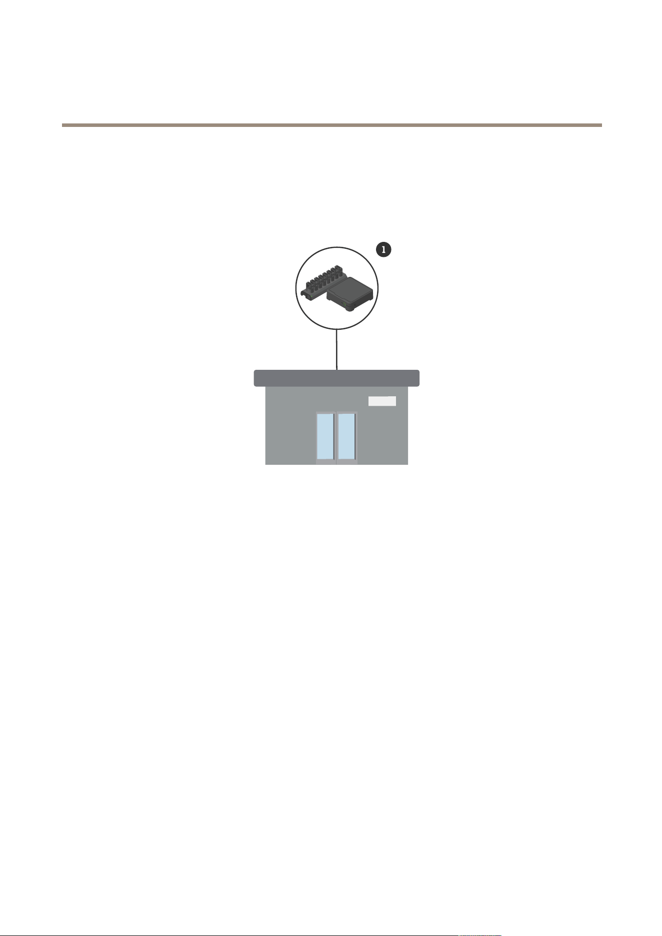
System overview
Headquarters’ system
1
Axis body worn system
Software requirements
Axis body worn system - AXIS OS version 12.3 or later
3

AXIS W401 Body W or n Activation Kit
Installation
Installation
For more information on how to install the AXIS W40 1 Body W orn Activation Kit, see the installation guide on the product’s
support page .
1. Connect the recording activation device to the I/O connector . See Product overview on page 28 .
NO NO
NO
TICE TICE
TICE
W e recommend that you install a 2 A fuse between the positive terminal of the battery and AXIS W40 1 Body W orn Activation
Kit. If you are unsure of how to install the hardware, contact a professional car uptter to do the installation.
2. Connect power to the power connector , or use P oE to power the device. See Product overview on page 28 .
Note
If both power connector and P oE are connected, the network will be connected via ethernet cable.
The device will switch to the wireless connection when you disconnect the ethernet cable.
4

AXIS W401 Body W or n Activation Kit
Get started
Get started
Find the device on the network
T o nd Axis devices on the network and assign them IP addresses in Windows®, use AXIS IP Utility or AXIS Device Manager . Both
applications are free and can be downloaded from axis.com/support .
For more information about how to nd and assign IP addresses, go to How to assign an IP address and access your device .
Browser support
Y ou can use the device with the following browsers:
Chrome
T M
Firefox
®
Edge
T M
Safari
®
Windows
®
recommended
recommended
macOS
®
recommended recommended
Linux
®
recommended recommended
Other operating systems *
*T o use AXIS OS web interface with iOS 15 or iP adOS 15, go to Settings Settings
Settings
> >
>
Safari Safari
Safari
> >
>
Advanced Advanced
Advanced
> >
>
Experimental Experimental
Experimental
Features Features
Features
and disable
NSURLSession W ebsocket.
If you need more information about recommended browsers, go to AXIS OS P ortal .
Open the device's web interface
1. Open a browser and type the IP address or host name of the Axis device.
If you do not know the IP address, use AXIS IP Utility or AXIS Device Manager to nd the device on the network.
2. T ype the username and password. If you access the device for the rst time, you must create an administrator account. See
Create an administrator account on page 5 .
For descriptions of all the controls and options in the device’s web interface, see The web interface on page 12 .
Create an administrator account
The rst time you log in to your device, you must create an administrator account.
1. Enter a username.
2. Enter a password. See Secure passwords on page 5 .
3. Re - enter the password.
4. Accept the license agreement.
5. Click Add account .
Important
The device has no default account. If you lose the password for your administrator account, you must reset the device. See
Reset to factory default settings on page 34 .
5

AXIS W401 Body W or n Activation Kit
Get started
Secure passwords
Important
Axis devices send the initially set password in clear text over the network. T o protect your device after the rst login, set
up a secure and encrypted HTTPS connection and then change the password.
The device password is the primary protection for your data and services. Axis devices do not impose a password policy as they
may be used in various types of installations.
T o protect your data we strongly recommend that you:
• Use a password with at least 8 characters, preferably created by a password generator .
• Don’t expose the password.
• Change the password at a recurring interval, at least once a year .
V erify that no one has tampered with the device software
T o make sure that the device has its original AXIS OS, or to take full control of the device after a security attack:
1. Reset to factory default settings. See Reset to factory default settings on page 34 .
After the reset, secure boot guarantees the state of the device.
2. Congure and install the device.
6

AXIS W401 Body W or n Activation Kit
Configur e your device
Configur e your device
This section covers all the important congurations that an installer needs to do to get the product up and running after the
hardware installation has been completed.
Set up rules for events
T o learn more, check out our guide Get started with rules for events .
T rigger an action
1. Go to System > Events and add a rule. The rule denes when the device will perform certain actions. Y ou can set
up rules as scheduled, recurring, or manually triggered.
2. Enter a Name .
3. Select the Condition that must be met to trigger the action. If you specify more than one condition for the rule, all of the
conditions must be met to trigger the action.
4. Select which Action the device should perform when the conditions are met.
Note
If you make changes to an active rule, the rule must be turned on again for the changes to take effect.
Detect tampering with input signal
This example explains how to send an email when the input signal is cut or short - circuited. For more information about the
I/O connector , see page 29 .
1. Go to System > Accessories > I/O ports and turn on Supervised for the relevant port.
Add an email recipient:
1. Go to System > Events > Recipients and add a recipient.
2. T ype a name for the recipient.
3. Select Email .
4. T ype an email address to send the email to.
5. The camera doesn’t have it’s own email server , so it has to log into another email server to send mails. Fill in the rest of the
information according to your email provider .
6. T o send a test email, click T est .
7. Click Save .
Create a rule:
1. Go to System > Events > Rules and add a rule.
2. T ype a name for the rule.
3. In the list of conditions, under I/O , select Supervised input tampering is active .
4. Select the relevant port.
5. In the list of actions, under Notications , select Send notication to email and then select the recipient from the list.
7

AXIS W401 Body W or n Activation Kit
Configur e your device
6. T ype a subject and a message for the email.
7. Click Save .
Activate a lamp when the window is opened
This example explains how to connect a window contact to a Body W orn Activation Kit, and how to set up an event to activate a
lamp when a window with a contact on it is opened.
Prerequisites
• Connect a 2 - wire cable (ground, I/O) to the window contact and to the I/O connector on the Body W orn Activation Kit.
• Connect the lamp to power and to the relay connector on the Body W orn Activation Kit.
Congure the I/O ports in the Body W orn Activation Kit
1. Go to System > Accessories .
2. Enter the following information in P ort 1 :
- Name : Window sensor
- Direction : Input
- Normal state : Closed circuit
3. Enter the following information in P ort 2 :
- Name : Lamp
- Direction : Output
- Normal state : Open circuit
Create two rules in the Body W orn Activation Kit
1. Go to System > Events and add a rule.
2. Enter the following information:
- Name : Window sensor
- Condition : Digital input
Select Use this condition as a trigger
- P ort : Window sensor
- Action : T oggle I/O while the rule is active
- P ort : Lamp
- State : Active
3. Click Save .
Activate the Body W orn Activation Kit over MQTT when camera detects motion
Prerequisites
• Congure a device for the I/O port 1 in the Body W orn Activation Kit.
• Set up an MQTT broker and get the broker’s IP address, username and password.
8

AXIS W401 Body W or n Activation Kit
Configur e your device
• Set up AXIS Motion Guard in the camera.
Set up the MQTT client in the camera
1. In the camera’s device interface, go to System > MQTT > MQTT client > Broker and enter the following information:
- Host : Broker IP address
- Client ID : For example Camera 1
- Protocol : The protocol the broker is set to
- P ort : The port number used by the broker
- The broker Username and P assword
2. Click Save and Connect .
Create two rules in the camera for MQTT publishing
1. Go to System > Events > Rules and add a rule.
2. Enter the following information:
- Name : Motion detected
- Condition : Applications > Motion alarm
- Action : MQTT > Send MQTT publish message
- T opic : Motion
- P ayload : On
- QoS : 0, 1 or 2
3. Click Save .
4. Add another rule with the following information:
- Name : No motion
- Condition : Applications > Motion alarm
- Select Invert this condition .
- Action : MQTT > Send MQTT publish message
- T opic : Motion
- P ayload : Off
- QoS : 0, 1 or 2
5. Click Save .
Set up the MQTT client in the Body W orn Activation Kit
1. In the Body W orn Activation Kit’s device interface, go to System > MQTT > MQTT client > Broker and enter the following
information:
- Host : Broker IP address
- Client ID : P ort 1
- Protocol : The protocol the broker is set to
9

AXIS W401 Body W or n Activation Kit
Configur e your device
- P ort : The port number used by the broker
- Username and P assword
2. Click Save and Connect .
3. Go to MQTT subscriptions and add a subscription.
Enter the following information:
- Subscription lter : Motion
- Subscription type : Stateful
- QoS : 0, 1 or 2
4. Click Save .
Create a rule in the Body W orn Activation Kit for MQTT subscriptions
1. Go to System > Events > Rules and add a rule.
2. Enter the following information:
- Name : Motion detected
- Condition : MQTT > Stateful
- Subscription lter : Motion
- P ayload : On
- Action : I/O > T oggle I/O while the rule is active
- P ort : I/O 1.
3. Click Save .
Open a lock when a button is pressed
This example explains how to connect a relay to the Body W orn Activation Kit and how to set up an event to open a lock when
someone presses a button connected to the Body W orn Activation Kit.
Prerequisites
• Connect a 2 - wire cable (COM, NO) to the lock and to the relay connector on the Body W orn Activation Kit.
• Connect a 2 - wire cable (ground, I/O) to the button and to the I/O connector on the Body W orn Activation Kit.
Congure the I/O ports in the Body W orn Activation Kit
1. Go to System > Accessories .
2. Enter the following information in P ort 1 :
- Name : Button
- Direction : Input
- Normal state : Open circuit
3. Enter the following information in P ort 9 :
- Name : Lock
- Normal state : Open circuit
1 0

AXIS W401 Body W or n Activation Kit
Configur e your device
Create a rule in the Body W orn Activation Kit
1. Go to System > Events and add a rule.
2. Enter the following information:
- Name : Open lock
- Condition : I/O > Digital input is active
Select Use this condition as a trigger
- P ort : Button
- Action : I/O > T oggle I/O once
- P ort : Lock
- State : Active
- Duration: 1 0 s
3. Click Save .
1 1
AXIS W401 Body W or n Activation Kit
The web inter face
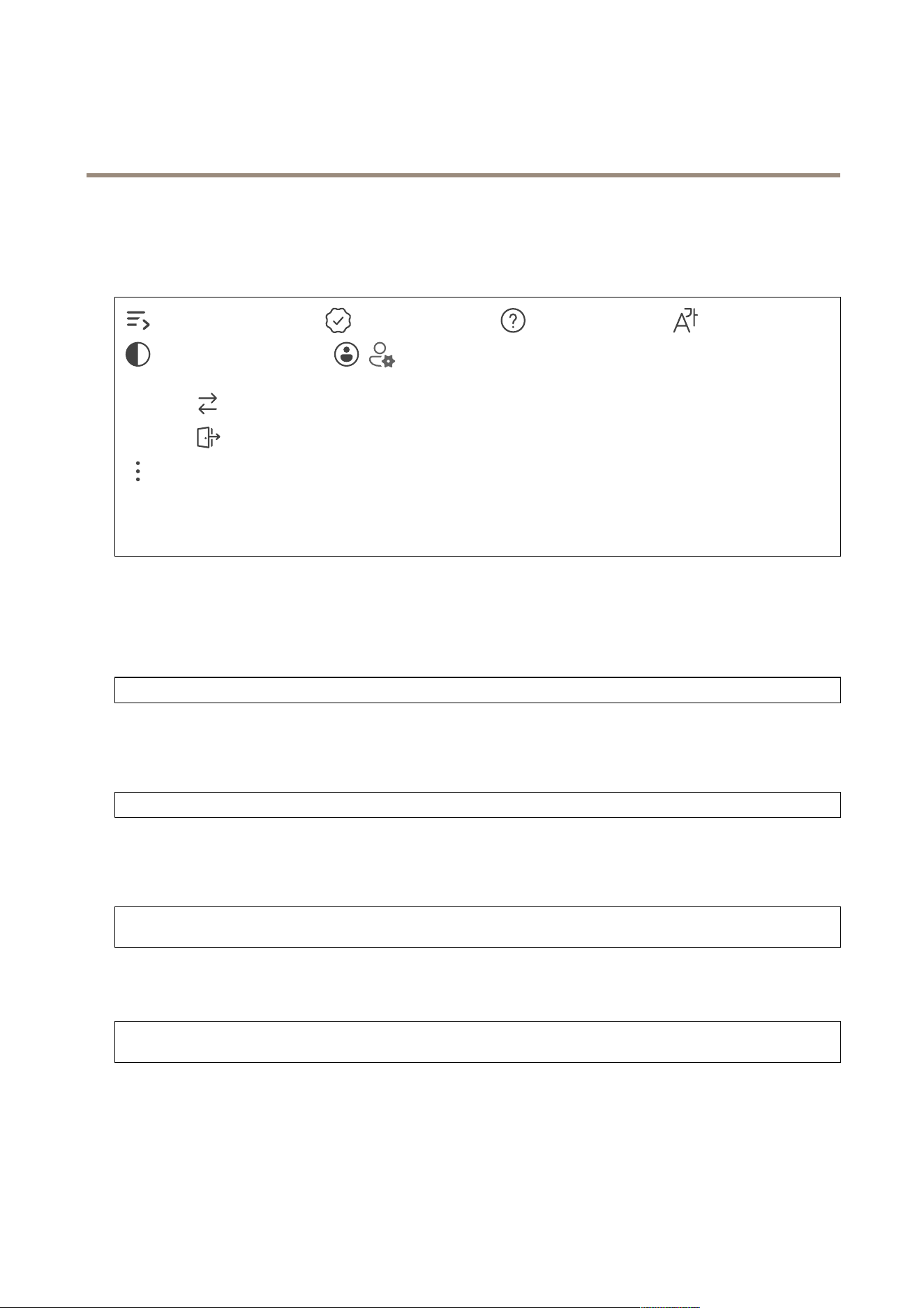
The web inter face
T o reach the device’s web interface, type the device’s IP address in a web browser .
Show or hide the main menu. Access the release notes. Access the product help. Change the language.
Set light theme or dark theme. The user menu contains:
• Information about the user who is logged in.
• Change account : Log out from the current account and log in to a new account.
• Log out : Log out from the current account.
The context menu contains:
• Analytics data : Accept to share non - personal browser data.
• Feedback : Share any feedback to help us improve your user experience.
• Legal : View information about cookies and licenses.
• About : View device information, including AXIS OS version and serial number .
Status
Device info
Shows the device information, including AXIS OS version and serial number .
Upgrade AXIS OS : Upgrade the software on your device. T akes you to the Maintenance page where you can do the upgrade.
Time sync status
Shows NTP synchronization information, including if the device is in sync with an NTP server and the time remaining until
the next sync.
NTP settings : View and update the NTP settings. T akes you to the Time and location page where you can change the NTP settings.
Security
Shows what kind of access to the device that is active, what encryption protocols are in use, and if unsigned apps are allowed.
Recommendations to the settings are based on the AXIS OS Hardening Guide.
Hardening guide : Link to AXIS OS Hardening guide where you can learn more about cybersecurity on Axis devices and best
practices.
Connected clients
Shows the number of connections and connected clients.
View details : View and update the list of connected clients. The list shows IP address, protocol, port, state, and PID/process
of each connection.
12

AXIS W401 Body W or n Activation Kit
The web inter face
Apps
Add app : Install a new app. Find more apps : Find more apps to install. Y ou will be taken to an overview page of Axis
apps. Allow unsigned apps : T urn on to allow installation of unsigned apps. Allow root - privileged apps : T urn on to
allow apps with root privileges full access to the device. View the security updates in AXIS OS and ACAP apps.
Note
The device’s performance might be affected if you run several apps at the same time.
Use the switch next to the app name to start or stop the app. Open : Access the app’s settings. The available settings depend on the
application. Some applications don’t have any settings. The context menu can contain one or more of the following options:
• Open - source license : View information about open - source licenses used in the app.
• App log : View a log of the app events. The log is helpful when you contact support.
• Activate license with a key : If the app requires a license, you need to activate it. Use this option if your device
doesn’t have internet access.
If you don’t have a license key , go to axis.com/products/analytics . Y ou need a license code and the Axis product serial
number to generate a license key .
• Activate license automatically : If the app requires a license, you need to activate it. Use this option if your device has
internet access. Y ou need a license code to activate the license.
• Deactivate the license : Deactivate the license to replace it with another license, for example, when you change from a
trial license to a full license. If you deactivate the license, you also remove it from the device.
• Settings : Congure the parameters.
• Delete : Delete the app permanently from the device. If you don’t deactivate the license rst, it remains active.
System
Time and location
Date and time
The time format depends on the web browser’s language settings.
Note
W e recommend you synchronize the device’s date and time with an NTP server .
Synchronization : Select an option for the device’s date and time synchronization.
• Automatic date and time (manual NTS KE servers) : Synchronize with the secure NTP key establishment servers
connected to the DHCP server .
- Manual NTS KE servers : Enter the IP address of one or two NTP servers. When you use two NTP servers,
the device synchronizes and adapts its time based on input from both.
- Max NTP poll time : Select the maximum amount of time the device should wait before it polls the NTP
server to get an updated time.
- Min NTP poll time : Select the minimum amount of time the device should wait before it polls the NTP
server to get an updated time.
• Automatic date and time (NTP servers using DHCP) : Synchronize with the NTP servers connected to the DHCP server .
- Fallback NTP servers : Enter the IP address of one or two fallback servers.
- Max NTP poll time : Select the maximum amount of time the device should wait before it polls the NTP
server to get an updated time.
- Min NTP poll time : Select the minimum amount of time the device should wait before it polls the NTP
server to get an updated time.
• Automatic date and time (manual NTP servers) : Synchronize with NTP servers of your choice.
- Manual NTP servers : Enter the IP address of one or two NTP servers. When you use two NTP servers, the
device synchronizes and adapts its time based on input from both.
13
AXIS W401 Body W or n Activation Kit
The web inter face
- Max NTP poll time : Select the maximum amount of time the device should wait before it polls the NTP
server to get an updated time.
- Min NTP poll time : Select the minimum amount of time the device should wait before it polls the NTP
server to get an updated time.
• Custom date and time : Manually set the date and time. Click Get from system to fetch the date and time settings
once from your computer or mobile device.
Time zone : Select which time zone to use. Time will automatically adjust to daylight saving time and standard time.
• DHCP : Adopts the time zone of the DHCP server . The device must connected to a DHCP server before you can select
this option.
• Manual : Select a time zone from the drop - down list.
Note
The system uses the date and time settings in all recordings, logs, and system settings.
Device location
Enter where the device is located. Y our video management system can use this information to place the device on a map.
• Format : Select the format to use when you enter your device's latitude and longitude.
• Latitude : P ositive values are north of the equator .
• Longitude : P ositive values are east of the prime meridian.
• Heading : Enter the compass direction that the device is facing. 0 is due north.
• Label : Enter a descriptive name for your device.
• Save : Click to save your device location.
WLAN
Congure custom network
Note
The device is currently connected via ethernet cable.
The device will switch to the wireless connection when you disconnect the ethernet cable.
If you'd like to join a hidden network or congure a network ahead of time, use Congure custom network button.
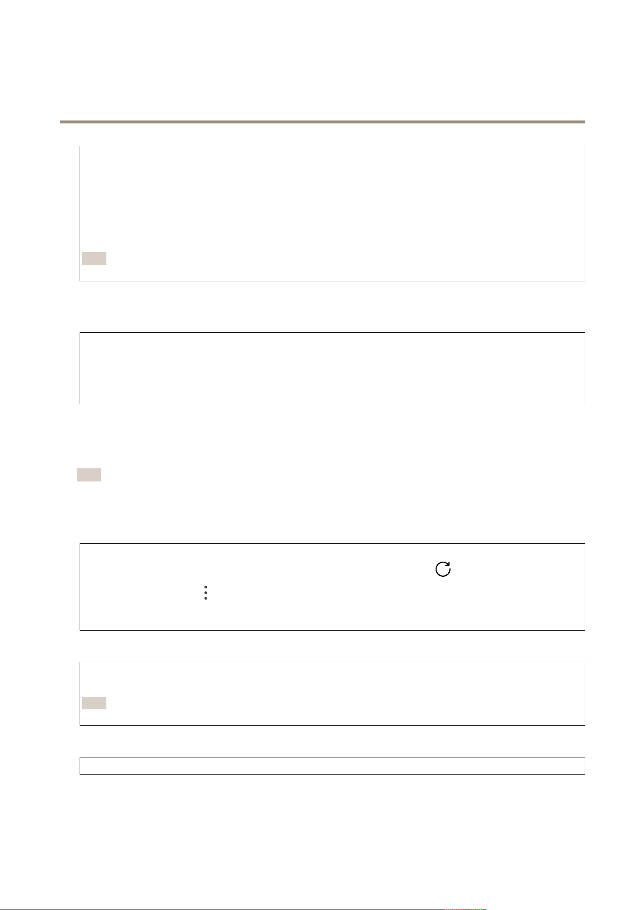
Congure custom network : Add a wireless network that doesn’t broadcast its SSID (name). Enter the SSID and all the required
settings for the network. Contact your network administrator to get the required settings. Refresh : Update the list of
available wireless networks. The context menu contains:
• Info : Show the signal strength, channel, and type of network security .
• Congure : Change the network settings.
IPv4
Assign IPv4 automatically : Select to let the network router assign an IP address to the device automatically . W e recommend
automatic IP (DHCP) for most networks. Fallback to static IP address if DHCP isn’t available : Select if you want to add a static IP
address to use as fallback if DHCP is unavailable and can’t assign an IP address automatically .
Note
If DHCP isn’t available and the device uses a static address fallback, the static address is congured with a limited scope.
IPv6
Assign IPv6 automatically : Select to turn on IPv6 and to let the network router assign an IP address to the device automatically .
14

AXIS W401 Body W or n Activation Kit
The web inter face
Network
IPv4
Assign IPv4 automatically : Select to let the network router assign an IP address to the device automatically . W e recommend
automatic IP (DHCP) for most networks. IP address : Enter a unique IP address for the device. Static IP addresses can be assigned
at random within isolated networks, provided that each address is unique. T o avoid conicts, we recommend you contact your
network administrator before you assign a static IP address. Subnet mask : Enter the subnet mask to dene what addresses are
inside the local area network. Any address outside the local area network goes through the router . Router : Enter the IP address of
the default router (gateway) used to connect devices that are attached to different networks and network segments. Fallback to
static IP address if DHCP isn’t available : Select if you want to add a static IP address to use as fallback if DHCP is unavailable
and can’t assign an IP address automatically .
Note
If DHCP isn’t available and the device uses a static address fallback, the static address is congured with a limited scope.
IPv6
Assign IPv6 automatically : Select to turn on IPv6 and to let the network router assign an IP address to the device automatically .
Hostname
Assign hostname automatically : Select to let the network router assign a hostname to the device automatically . Hostname : Enter
the hostname manually to use as an alternative way of accessing the device. The server report and system log use the hostname.
Allowed characters are A–Z, a–z, 0–9 and -. Enable dynamic DNS updates : Allow your device to automatically update its
domain name server records whenever its IP address changes. Register DNS name : Enter a unique domain name that points to
your device's IP address. Allowed characters are A–Z, a–z, 0–9 and -. TTL : Time to Live (TTL) sets how long a DNS record stays
valid before it needs to be updated.
DNS servers
Assign DNS automatically : Select to let the DHCP server assign search domains and DNS server addresses to the device
automatically . W e recommend automatic DNS (DHCP) for most networks. Search domains : When you use a hostname that is
not fully qualied, click Add search domain and enter a domain in which to search for the hostname the device uses. DNS
servers : Click Add DNS server and enter the IP address of the DNS server . This provides the translation of hostnames to IP
addresses on your network.
HTTP and HTTPS
HTTPS is a protocol that provides encryption for page requests from users and for the pages returned by the web server . The encrypted
exchange of information is governed by the use of an HTTPS certicate, which guarantees the authenticity of the server .
T o use HTTPS on the device, you must install an HTTPS certicate. Go to System > Security to create and install certicates.
Allow access through : Select if a user is allowed to connect to the device through the HTTP , HTTPS , or both HTTP and HTTPS
protocols.
Note
If you view encrypted web pages through HTTPS, you might experience a drop in performance, especially when you
request a page for the rst time.
HTTP port : Enter the HTTP port to use. The device allows port 80 or any port in the range 1 0 24 - 65535. If you are logged in as
an administrator , you can also enter any port in the range 1 - 1 0 23. If you use a port in this range, you get a warning. HTTPS
port : Enter the HTTPS port to use. The device allows port 443 or any port in the range 1 0 24 - 65535. If you are logged in as an
administrator , you can also enter any port in the range 1 - 1 0 23. If you use a port in this range, you get a warning. Certicate :
Select a certicate to enable HTTPS for the device.
Network discovery protocols
15

AXIS W401 Body W or n Activation Kit
The web inter face
Bonjour
®
: T urn on to allow automatic discovery on the network. Bonjour name : Enter a friendly name to be visible on the network.
The default name is the device name and MAC address. UPnP
®
: T urn on to allow automatic discovery on the network. UPnP name :
Enter a friendly name to be visible on the network. The default name is the device name and MAC address. WS - Discovery : T urn on
to allow automatic discovery on the network. LLDP and CDP : T urn on to allow automatic discovery on the network. T urning LLDP
and CDP off can impact the P oE power negotiation. T o resolve any issues with the P oE power negotiation, congure the P oE
switch for hardware P oE power negotiation only .
One - click cloud connection
One - click cloud connection (O3C) together with an O3C service provides easy and secure internet access to live and recorded video
from any location. For more information, see axis.com/end - to - end - solutions/hosted - services .
Allow O3C :
• One - click : This is the default setting. Press and hold the control button on the device to connect to an O3C service
over the internet. Y ou need to register the device with the O3C service within 24 hours after you press the control
button. Otherwise, the device disconnects from the O3C service. Once you register the device, Always is enabled and
the device stays connected to the O3C service.
• Always : The device constantly attempts to connect to an O3C service over the internet. Once you register the device,
it stays connected to the O3C service. Use this option if the control button on the device is out of reach.
• No : Disables the O3C service.
Proxy settings : If needed, enter the proxy settings to connect to the proxy server . Host : Enter the proxy server’s address. P ort : Enter
the port number used for access. Login and P assword : If needed, enter username and password for the proxy server . Authentication
method :
• Basic : This method is the most compatible authentication scheme for HTTP . It’s less secure than the Digest method
because it sends the username and password unencrypted to the server .
• Digest : This method is more secure because it always transfers the password encrypted across the network.
• Auto : This option lets the device select the authentication method depending on the supported methods. It prioritizes
the Digest method over the Basic method.
Owner authentication key (OAK) : Click Get key to fetch the owner authentication key . This is only possible if the device is
connected to the internet without a rewall or proxy .
SNMP
The Simple Network Management Protocol (SNMP) allows remote management of network devices.
SNMP : Select the version of SNMP to use.
• v1 and v2c :
- Read community : Enter the community name that has read - only access to all supported SNMP objects. The
default value is public .
- Write community : Enter the community name that has read or write access to all supported SNMP objects
(except read - only objects). The default value is write .
- Activate traps : T urn on to activate trap reporting. The device uses traps to send messages for important
events or status changes to a management system. In the web interface, you can set up traps for SNMP v1
and v2c. T raps are automatically turned off if you change to SNMP v3 or turn off SNMP . If you use SNMP v3,
you can set up traps through the SNMP v3 management application.
- T rap address : Enter the IP address or host name of the management server .
- T rap community : Enter the community to use when the device sends a trap message to the management
system.
- T raps :
- Cold start : Sends a trap message when the device starts.
- W arm start : Sends a trap message when you change an SNMP setting.
- Link up : Sends a trap message when a link changes from down to up.
- Authentication failed : Sends a trap message when an authentication attempt fails.
Note
All Axis Video MIB traps are enabled when you turn on SNMP v1 and v2c traps. For more information, see
AXIS OS P ortal > SNMP .
• v3 : SNMP v3 is a more secure version, which provides encryption and secure passwords. T o use SNMP v3, we
recommend you to activate HTTPS, as the password is then sent through HTTPS. This also prevents unauthorized
16

AXIS W401 Body W or n Activation Kit
The web inter face
parties’ access to unencrypted SNMP v1 and v2c traps. If you use SNMP v3, you can set up traps through the SNMP v3
management application.
- P assword for the account “initial” : Enter the SNMP password for the account named “initial”. Although the
password can be sent without activating HTTPS, we don’t recommend it. The SNMP v3 password can only
be set once, and preferably only when HTTPS is enabled. Once the password is set, the password eld is no
longer displayed. T o set the password again, you must reset the device to factory default settings.
Security
Certicates
Certicates are used to authenticate devices on a network. The device supports two types of certicates:
• Client/server certicates
A client/server certicate validates the device’s identity , and can be self - signed or issued by a Certicate Authority (CA).
A self - signed certicate offers limited protection and can be used before a CA - issued certicate has been obtained.
• CA certicates
Y ou can use a CA certicate to authenticate a peer certicate, for example to validate the identity of an authentication
server when the device connects to a network protected by IEEE 80 2.1X. The device has several pre - installed CA
certicates.
These formats are supported:
• Certicate formats: .PEM, .CER, and .PFX
• Private key formats: PKCS#1 and PKCS#12
Important
If you reset the device to factory default, all certicates are deleted. Any pre - installed CA certicates are reinstalled.
Add certicate : Click to add a certicate.
• More : Show more elds to ll in or select.
• Secure keystore : Select to use Secure element or T rusted Platform Module 2.0 to securely store the private key . For
more information on which secure keystore to select, go to help.axis.com/en - us/axis - os#cryptographic - support .
• K ey type : Select the default or a different encryption algorithm from the drop - down list to protect the certicate.
The context menu contains:
• Certicate information : View an installed certicate’s properties.
• Delete certicate : Delete the certicate.
• Create certicate signing request : Create a certicate signing request to send to a registration authority to apply
for a digital identity certicate.
Secure keystore :
• Secure element (CC EAL6+) : Select to use secure element for secure keystore.
• T rusted Platform Module 2.0 (CC EAL4+, FIPS 140 - 2 Level 2) : Select to use TPM 2.0 for secure keystore.
Network access control and encryption
IEEE 80 2.1x IEEE 80 2.1x is an IEEE standard for port - based network admission control providing secure authentication of wired
and wireless network devices. IEEE 80 2.1x is based on EAP (Extensible Authentication Protocol).T o access a network protected
by IEEE 80 2.1x, network devices must authenticate themselves. The authentication is performed by an authentication server ,
typically a RADIUS server (for example, FreeRADIUS and Microsoft Internet Authentication Server). IEEE 80 2.1AE MACsec IEEE
80 2.1AE MACsec is an IEEE standard for media access control (MAC) security that denes connectionless data condentiality
and integrity for media access independent protocols. Certicates When congured without a CA certicate, server certicate
validation is disabled and the device tries to authenticate itself regardless of what network it is connected to.When using a
certicate, in Axis' implementation, the device and the authentication server authenticate themselves with digital certicates
using EAP - TLS (Extensible Authentication Protocol - T ransport Layer Security).T o allow the device to access a network protected
through certicates, you must install a signed client certicate on the device. Authentication method : Select an EAP type used for
authentication. Client certicate : Select a client certicate to use IEEE 80 2.1x. The authentication server uses the certicate
to validate the client’s identity . CA certicates : Select CA certicates to validate the authentication server’s identity . When no
certicate is selected, the device tries to authenticate itself regardless of what network it is connected to. EAP identity : Enter the
user identity associated with the client certicate. EAPOL version : Select the EAPOL version that is used in the network switch. Use
17
AXIS W401 Body W or n Activation Kit
The web inter face
IEEE 80 2.1x : Select to use the IEEE 80 2.1x protocol.These settings are only available if you use IEEE 80 2.1x PEAP - MSCHAPv2 as
the authentication method:
• P assword : Enter the password for your user identity .
• P eap version : Select the P eap version that is used in the network switch.
• Label : Select 1 to use client EAP encryption; select 2 to use client PEAP encryption. Select the Label that the network
switch uses when using P eap version 1.
These settings are only available if you use IEEE 80 2.1ae MACsec (Static CAK/Pre - Shared K ey) as the authentication method:
• K ey agreement connectivity association key name : Enter the connectivity association name (CKN). It must be 2 to 64
(divisible by 2) hexadecimal characters. The CKN must be manually congured in the connectivity association and
must match on both ends of the link to initially enable MACsec.
• K ey agreement connectivity association key : Enter the connectivity association key (CAK). It should be either 32
or 64 hexadecimal characters long. The CAK must be manually congured in the connectivity association and must
match on both ends of the link to initially enable MACsec.
Prevent brute - force attacks
Blocking : T urn on to block brute - force attacks. A brute - force attack uses trial - and - error to guess login info or encryption
keys. Blocking period : Enter the number of seconds to block a brute - force attack. Blocking conditions : Enter the number of
authentication failures allowed per second before the block starts. Y ou can set the number of failures allowed both on page
level and device level.
Firewall
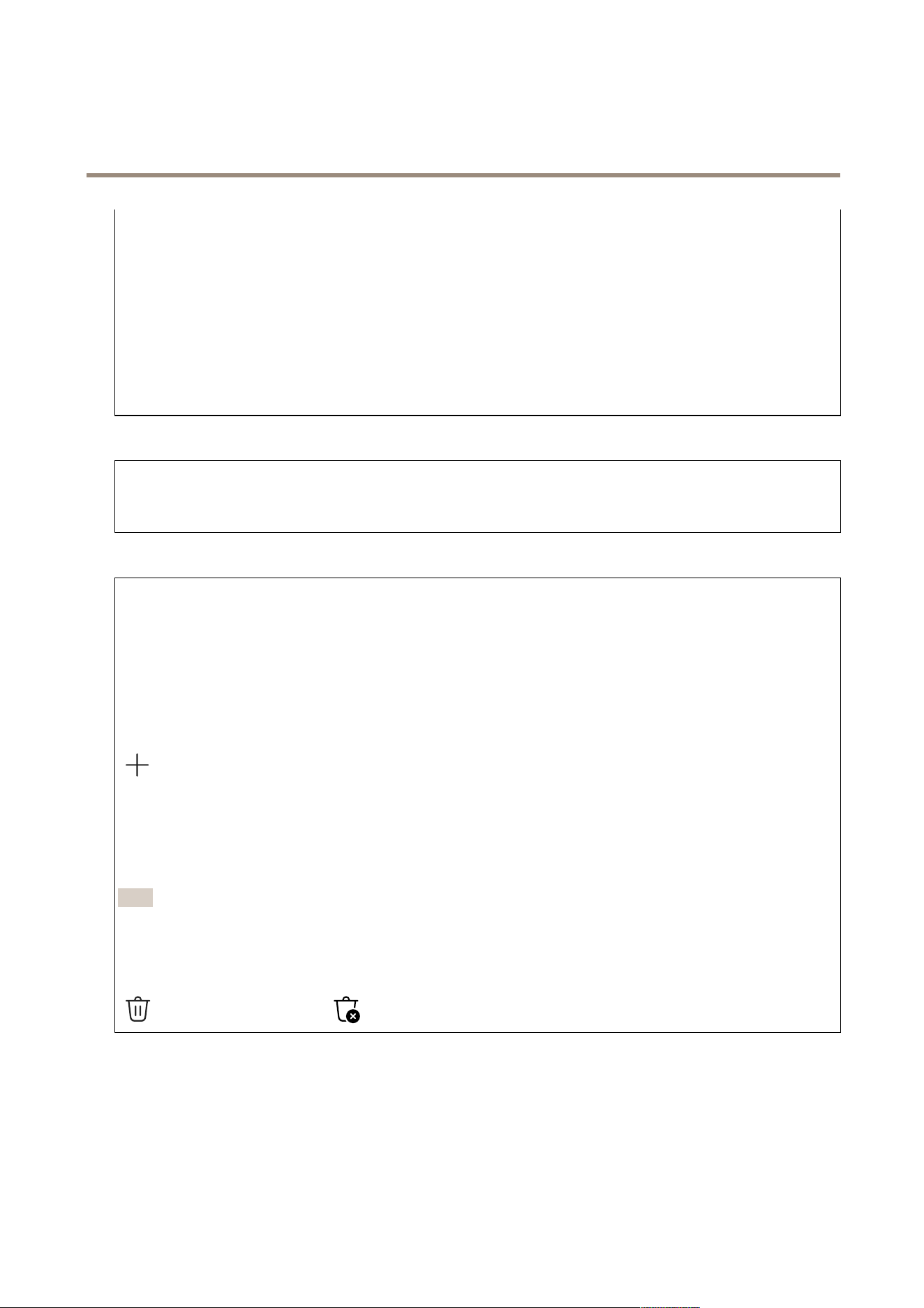
Activate : T urn on the rewall.
Default P olicy : Select the default state for the rewall.
• Allow: Allows all connections to the device. This option is set by default.
• Deny: Denies all connections to the device.
T o make exceptions to the default policy , you can create rules that allows or denies connections to the device from specic
addresses, protocols, and ports.
• Address : Enter an address in IPv4/IPv6 or CIDR format that you want to allow or deny access to.
• Protocol : Select a protocol that you want to allow or deny access to.
• P ort : Enter a port number that you want to allow or deny access to. Y ou can add a port number between 1 and 65535.
• P olicy : Select the policy of the rule.
: Click to create another rule.
Add rules: Click to add the rules that you have dened.
• Time in seconds: Set a time limit for testing the rules. The default time limit is set to 300 seconds. T o activate the
rules straight away , set the time to 0 seconds.
• Conrm rules: Conrm the rules and their time limit. If you have set a time limit of more than 1 second, the rules will
be active during this time. If you have set the time to 0 , the rules will be active straight away .
P ending rules : An overview of the latest tested rules that you are yet to conrm.
Note
The rules that have a time limit appear under Active rules until the displayed timer runs out, or until you conrm them. If
you don't conrm them, they will appear under P ending rules once the timer runs out, and the rewall will revert to the
previously dened settings. If you conrm them, they will replace the current active rules.
Conrm rules : Click to activate the pending rules. Active rules : An overview of the rules you are currently running on the device.
: Click to delete an active rule. : Click to delete all rules, both pending and active.
Custom signed AXIS OS certicate
18
AXIS W401 Body W or n Activation Kit
The web inter face
T o install test software or other custom software from Axis on the device, you need a custom signed AXIS OS certicate. The
certicate veries that the software is approved by both the device owner and Axis. The software can only run on a specic device
which is identied by its unique serial number and chip ID. Only Axis can create custom signed AXIS OS certicates, since Axis
holds the key to sign them. Install : Click to install the certicate. Y ou need to install the certicate before you install the
software. The context menu contains:
• Delete certicate : Delete the certicate.
Accounts
Accounts
Add account : Click to add a new account. Y ou can add up to 1 00 accounts. Account : Enter a unique account name. New
password : Enter a password for the account. P asswords must be 1 to 64 characters long. Only ASCII printable characters (code
32 to 126) are allowed in the password, for example, letters, numbers, punctuation, and some symbols. Repeat password : Enter
the same password again. Privileges :
• Administrator : Has full access to all settings. Administrators can also add, update, and remove other accounts.
• Operator : Has access to all settings except:
- All System settings.
• Viewer : Doesn’t have access to change any settings.
The context menu contains: Update account : Edit the account properties. Delete account : Delete the account. Y ou can’t
delete the root account.
Anonymous access
Allow anonymous viewing : T urn on to allow anyone access the device as a viewer without logging in with an account. Allow
anonymous PTZ operating : T urn on to allow anonymous users to pan, tilt, and zoom the image.
SSH accounts
Add SSH account : Click to add a new SSH account.
• Restrict root access : T urn on to restrict functionality that requires root access.
• Enable SSH : T urn on to use SSH service.
Account : Enter a unique account name. New password : Enter a password for the account. P asswords must be 1 to 64 characters
long. Only ASCII printable characters (code 32 to 126) are allowed in the password, for example, letters, numbers, punctuation,
and some symbols. Repeat password : Enter the same password again. Comment : Enter a comment (optional). The context
menu contains: Update SSH account : Edit the account properties. Delete SSH account : Delete the account. Y ou can’t delete the
root account.
OpenID Conguration
Important
If you can't use OpenID to sign in, use the Digest or Basic credentials you used when you congured OpenID to sign in.
Client ID : Enter the OpenID username. Outgoing Proxy : Enter the proxy address for the OpenID connection to use a proxy
server . Admin claim : Enter a value for the admin role. Provider URL : Enter the web link for the API endpoint authentication. Format
should be https://[insert URL]/.well - known/openid - conguration Operator claim : Enter a value for the operator role. Require claim :
Enter the data that should be in the token. Viewer claim : Enter the value for the viewer role. Remote user : Enter a value to identify
remote users. This assists to display the current user in the device’s web interface. Scopes : Optional scopes that could be part of
the token. Client secret : Enter the OpenID password Save : Click to save the OpenID values. Enable OpenID : T urn on to close current
connection and allow device authentication from the provider URL.
19

AXIS W401 Body W or n Activation Kit
The web inter face
Events
Rules
A rule denes the conditions that triggers the product to perform an action. The list shows all the currently congured rules in
the product.
Note
Y ou can create up to 256 action rules.
Add a rule : Create a rule. Name : Enter a name for the rule. W ait between actions : Enter the minimum time (hh:mm:ss)
that must pass between rule activations. It is useful if the rule is activated by , for example, day - night mode conditions, to avoid
that small light changes during sunrise and sunset activate the rule repeatedly . Condition : Select a condition from the list. A
condition must be met for the device to perform an action. If multiple conditions are dened, all of them must be met to trigger
the action. For information about specic conditions, see Get started with rules for events . Use this condition as a trigger : Select
to make this rst condition function only as a starting trigger . It means that once the rule is activated, it remains active for as long
as all the other conditions are met, no matter the state of the rst condition. If you don’t select this option, the rule will simply be
active whenever all the conditions are met. Invert this condition : Select if you want the condition to be the opposite of your
selection. Add a condition : Click to add an additional condition. Action : Select an action from the list and enter its
required information. For information about specic actions, see Get started with rules for events .
Recipients
Y ou can set up your device to notify recipients about events or send les.
Note
If you set up your device to use FTP or SFTP , don’t change or remove the unique sequence number that’s added to the le
names. If you do that, only one image per event can be sent.
The list shows all the recipients currently congured in the product, along with information about their conguration.
Note
Y ou can create up to 20 recipients.
Add a recipient : Click to add a recipient. Name : Enter a name for the recipient. T ype : Select from the list:
• FTP
- Host : Enter the server's IP address or hostname. If you enter a hostname, make sure that a DNS server is
specied under System > Network > IPv4 and IPv6 .
- P ort : Enter the port number used by the FTP server . The default is 2 1.
- Folder : Enter the path to the directory where you want to store les. If this directory doesn’t already exist
on the FTP server , you will get an error message when uploading les.
- Username : Enter the username for the login.
- P assword : Enter the password for the login.
- Use temporary le name : Select to upload les with temporary , automatically generated lenames. The
les get renamed to the desired names when the upload completes. If the upload is aborted/interrupted,
you don’t get any corrupt les. However , you probably still get the temporary les. This way you know
that all les that have the desired name are correct.
- Use passive FTP : Under normal circumstances, the product simply requests the target FTP server to open the
data connection. The device actively initiates both the FTP control and data connections to the target server .
This is normally needed if there is a rewall between the device and the target FTP server .
• HTTP
- URL : Enter the network address to the HTTP server and the script that will handle the request. For example,
http://192.168.254.1 0/cgi - bin/notify .cgi.
- Username : Enter the username for the login.
20

AXIS W401 Body W or n Activation Kit
The web inter face
- P assword : Enter the password for the login.
- Proxy : T urn on and enter the required information if a proxy server must be passed to connect to the HTTP
server .
• HTTPS
- URL : Enter the network address to the HTTPS server and the script that will handle the request. For example,
https://192.168.254.1 0/cgi - bin/notify .cgi.
- V alidate server certicate : Select to validate the certicate that was created by HTTPS server .
- Username : Enter the username for the login.
- P assword : Enter the password for the login.
- Proxy : T urn on and enter the required information if a proxy server must be passed to connect to the HTTPS
server .
• Network storage
Y ou can add network storage such as NAS (network - attached storage) and use it as a recipient to store les. The les
are stored in the Matroska (MKV) le format.
- Host : Enter the IP address or hostname for the network storage.
- Share : Enter the name of the share on the host.
- Folder : Enter the path to the directory where you want to store les.
- Username : Enter the username for the login.
- P assword : Enter the password for the login.
• SFTP
- Host : Enter the server's IP address or hostname. If you enter a hostname, make sure that a DNS server is
specied under System > Network > IPv4 and IPv6 .
- P ort : Enter the port number used by the SFTP server . The default is 22.
- Folder : Enter the path to the directory where you want to store les. If this directory doesn’t already exist on
the SFTP server , you will get an error message when uploading les.
- Username : Enter the username for the login.
- P assword : Enter the password for the login.
- SSH host public key type (MD5) : Enter the ngerprint of the remote host’s public key (a 32 - digit
hexadecimal string). The SFTP client supports SFTP servers using SSH - 2 with RSA, DSA, ECDSA, and ED255 19
host key types. RSA is the preferred method during negotiation, followed by ECDSA, ED255 19, and DSA. Make
sure to enter the right MD5 host key that is used by your SFTP server . While the Axis device supports both
MD5 and SHA - 256 hash keys, we recommend using SHA - 256 due to stronger security over MD5. For more
information on how to congure an SFTP server with an Axis device, go to the AXIS OS P ortal .
- SSH host public key type (SHA256) : Enter the ngerprint of the remote host’s public key (a 43 - digit Base64
encoded string). The SFTP client supports SFTP servers using SSH - 2 with RSA, DSA, ECDSA, and ED255 19 host
key types. RSA is the preferred method during negotiation, followed by ECDSA, ED255 19, and DSA. Make
sure to enter the right MD5 host key that is used by your SFTP server . While the Axis device supports both
MD5 and SHA - 256 hash keys, we recommend using SHA - 256 due to stronger security over MD5. For more
information on how to congure an SFTP server with an Axis device, go to the AXIS OS P ortal .
- Use temporary le name : Select to upload les with temporary , automatically generated lenames. The
les get renamed to the desired names when the upload completes. If the upload is aborted or interrupted,
you don’t get any corrupt les. However , you probably still get the temporary les. This way , you know
that all les that have the desired name are correct.
• SIP or VMS :
SIP : Select to make a SIP call.
VMS : Select to make a VMS call.
- From SIP account : Select from the list.
- T o SIP address : Enter the SIP address.
- T est : Click to test that your call settings works.
• Email
- Send email to : Enter the email address to send emails to. T o enter multiple addresses, use commas to
separate them.
- Send email from : Enter the email address of the sending server .
- Username : Enter the username for the mail server . Leave this eld empty if the mail server does not
require authentication.
- P assword : Enter the password for the mail server . Leave this eld empty if the mail server does not require
authentication.
- Email server (SMTP) : Enter the name of the SMTP server , for example, smtp.gmail.com, smtp.mail.yahoo.com.
- P ort : Enter the port number for the SMTP server , using values in the range 0 - 65535. The default value is 587.
2 1

AXIS W401 Body W or n Activation Kit
The web inter face
- Encryption : T o use encryption, select either SSL or TLS.
- V alidate server certicate : If you use encryption, select to validate the identity of the device. The certicate
can be self - signed or issued by a Certicate Authority (CA).
- POP authentication : T urn on to enter the name of the POP server , for example, pop.gmail.com.
Note
Some email providers have security lters that prevent users from receiving or viewing large amount of
attachments, from receiving scheduled emails and similar . Check the email provider's security policy to avoid
your email account being locked or missing out on your expected emails.
• T CP
- Host : Enter the server's IP address or hostname. If you enter a hostname, make sure that a DNS server is
specied under System > Network > IPv4 and IPv6 .
- P ort : Enter the port number used to access the server .
T est : Click to test the setup. The context menu contains: View recipient : Click to view all the recipient details. Copy
recipient : Click to copy a recipient. When you copy , you can make changes to the new recipient. Delete recipient : Click to delete
the recipient permanently .
Schedules
Schedules and pulses can be used as conditions in rules. The list shows all the schedules and pulses currently congured in the
product, along with information about their conguration. Add schedule : Click to create a schedule or pulse.
Manual triggers
Y ou can use the manual trigger to manually trigger a rule. The manual trigger can, for example, be used to validate actions
during product installation and conguration.
MQTT
MQTT (Message Queuing T elemetry T ransport) is a standard messaging protocol for the Internet of Things (IoT). It was designed for
simplied IoT integration and is used in a wide variety of industries to connect remote devices with a small code footprint and
minimal network bandwidth. The MQTT client in Axis device software can simplify integration of data and events produced in the
device to systems which are not video management software (VMS).Set up the device as an MQTT client. MQTT communication is
based on two entities, the clients and the broker . The clients can send and receive messages. The broker is responsible for routing
messages between clients.Y ou can learn more about MQTT in AXIS OS P ortal .
ALPN
ALPN is a TLS/SSL extension that allows for the selection of an application protocol during the handshake phase of the connection
between the client and server . This is used to enable MQTT trafc over the same port that is used for other protocols, such as HTTP .
In some cases, there might not be a dedicated port open for MQTT communication. A solution in such cases is to use ALPN to
negotiate the use of MQTT as the application protocol on a standard port, allowed by the rewalls.
MQTT client
22
AXIS W401 Body W or n Activation Kit
The web inter face
Connect : T urn on or off the MQTT client. Status : Shows the current status of the MQTT client. BrokerHost : Enter the hostname or
IP address of the MQTT server . Protocol : Select which protocol to use. P ort : Enter the port number .
• 1883 is the default value for MQTT over T CP
• 8883 is the default value for MQTT over SSL
• 80 is the default value for MQTT over W ebSocket
• 443 is the default value for MQTT over W ebSocket Secure
ALPN protocol : Enter the ALPN protocol name provided by your MQTT broker provider . This is only applicable with MQTT over SSL
and MQTT over W ebSocket Secure. Username : Enter the username that the client will use to access the server . P assword : Enter
a password for the username. Client ID : Enter a client ID. The client identier is sent to the server when the client connects to
it. Clean session : Controls the behavior at connection and disconnection time. When selected, the state information is discarded at
connect and disconnect. HTTP proxy : A URL with a maximum length of 255 bytes. Y ou can leave the eld empty if you don't want
to use an HTTP proxy . HTTPS proxy : A URL with a maximum length of 255 bytes. Y ou can leave the eld empty if you don't want to
use an HTTPS proxy . K eep alive interval : Enables the client to detect when the server is no longer available without having to wait
for the long T CP/IP timeout. Timeout : The time interval in seconds to allow a connect to complete. Default value: 60 Device topic
prex : Used in the default values for the topic in the connect message and L WT message on the MQTT client tab , and in the
publication conditions on the MQTT publication tab . Reconnect automatically : Species whether the client should reconnect
automatically after a disconnect. Connect message Species if a message should be sent out when a connection is established. Send
message : T urn on to send messages. Use default : T urn off to enter your own default message. T opic : Enter the topic for the default
message. P ayload : Enter the content for the default message. Retain : Select to keep the state of client on this T opicQoS : Change
the QoS layer for the packet ow . Last Will and T estament message The Last Will T estament (L WT) lets a client provide a testament
along with its credentials when connecting to the broker . If the client disconnects ungracefully at some point later (maybe because
his power source died), it can let the broker deliver a message to other clients. This L WT message has the same form as an ordinary
message and gets routed via the same mechanics. Send message : T urn on to send messages. Use default : T urn off to enter your
own default message. T opic : Enter the topic for the default message. P ayload : Enter the content for the default message. Retain :
Select to keep the state of client on this T opicQoS : Change the QoS layer for the packet ow .
MQTT publication
Use default topic prex : Select to use the default topic prex, that is dened in the device topic prex in the MQTT client
tab . Include topic name : Select to include the topic that describes the condition in the MQTT topic. Include topic namespaces :
Select to include ONVIF topic namespaces in the MQTT topic. Include serial number : Select to include the device’s serial number in
the MQTT payload. Add condition : Click to add a condition. Retain : Denes which MQTT messages are sent as retained.
• None : Send all messages as non - retained.
• Property : Send only stateful messages as retained.
• All : Send both stateful and stateless messages as retained.
QoS : Select the desired level for the MQTT publication.
MQTT subscriptions
Add subscription : Click to add a new MQTT subscription. Subscription lter : Enter the MQTT topic that you want to
subscribe to. Use device topic prex : Add the subscription lter as prex to the MQTT topic. Subscription type :
• Stateless : Select to convert MQTT messages into a stateless message.
• Stateful : Select to convert MQTT messages into a condition. The payload is used as the state.
QoS : Select the desired level for the MQTT subscription.
MQTT overlays
23

AXIS W401 Body W or n Activation Kit
The web inter face
Note
Connect to an MQTT broker before you add MQTT overlay modiers.
Add overlay modier : Click to add a new overlay modier . T opic lter : Add the MQTT topic that contains the data you want
to show in the overlay . Data eld : Specify the key for the message payload that you want to show in the overlay , assuming the
message is in JSON format.
Modier : Use the resulting modier when you create the overlay .
• Modiers that start with #XMP show all of the data received from the topic.
• Modiers that start with #XMD show the data specied in the data eld.
ONVIF
ONVIF accounts
ONVIF (Open Network Video Interface Forum) is a global interface standard that makes it easier for end - users, integrators,
consultants, and manufacturers to take advantage of the possibilities offered by network video technology . ONVIF enables
interoperability between different vendor products, increased exibility , reduced cost and future - proof systems.
When you create an ONVIF account, you automatically enable ONVIF communication. Use the account name and password for all
ONVIF communication with the device. For more information see the Axis Developer Community at axis.com .
Add accounts : Click to add a new ONVIF account. Account : Enter a unique account name. New password : Enter a password
for the account. P asswords must be 1 to 64 characters long. Only ASCII printable characters (code 32 to 126) are allowed in the
password, for example, letters, numbers, punctuation, and some symbols. Repeat password : Enter the same password again. Role :
• Administrator : Has full access to all settings. Administrators can also add, update, and remove other accounts.
• Operator : Has access to all settings except:
- All System settings.
- Adding apps.
• Media account : Allows access to the video stream only .
The context menu contains: Update account : Edit the account properties. Delete account : Delete the account. Y ou can’t
delete the root account.
P ower setting
DC power input:
Important
T o avoid unwanted shutdown, only turn on Delayed shutdown when the ignition is physically connected to the main unit.
Note
If the device has been without power before it is turned on, a delay occurs before Delayed shutdown is activated.
1. Connect to ignition control on the 3 - pin terminal block.
2. Go to the device’s web interface.
3. Go to System > P ower settings and turn on Delayed shutdown .
24

AXIS W401 Body W or n Activation Kit
The web inter face
4. Set a delay time between 1 and 60 minutes.
Accessories
I/O ports
Use digital input to connect external devices that can toggle between an open and closed circuit, for example, PIR sensors, door
or window contacts, and glass break detectors.
Use digital output to connect external devices such as relays and LEDs. Y ou can activate connected devices through the VAPIX®
Application Programming Interface or the web interface.
P ortName : Edit the text to rename the port. Direction : indicates that the port is an input port. indicates that it’s an
output port. If the port is congurable, you can click the icons to change between input and output. Normal state : Click for
open circuit, and for closed circuit. Current state : Shows the current state of the port. The input or output is activated
when the current state is different from the normal state. An input on the device has an open circuit when it’s disconnected or
when there is a voltage above 1 VDC.
Note
During restart, the output circuit is open. When the restart is complete, the circuit goes back to the normal position. If you
change any settings on this page, the output circuits go back to their normal positions regardless of any active triggers.
Supervised : T urn on to make it possible to detect and trigger actions if someone tampers with the connection to digital
I/O devices. In addition to detecting if an input is open or closed, you can also detect if someone has tampered with it (that is, cut
or shorted). T o supervise the connection requires additional hardware (end - of - line resistors) in the external I/O loop.
Logs
Reports and logs
Reports
• View the device server report : View information about the product status in a pop - up window . The Access Log is
automatically included in the Server Report.
• Download the device server report : It creates a .zip le that contains a complete server report text le in UTF–8
format, as well as a snapshot of the current live view image. Always include the server report .zip le when you
contact support.
• Download the crash report : Download an archive with detailed information about the server's status. The crash report
contains information that is in the server report as well as detailed debug information. This report might contain
sensitive information such as network traces. It can take several minutes to generate the report.
Logs
• View the system log : Click to show information about system events such as device startup, warnings, and critical
messages.
• View the access log : Click to show all failed attempts to access the device, for example, when a wrong login
password is used.
Network trace
Important
A network trace le might contain sensitive information, for example certicates or passwords.
A network trace le can help you troubleshoot problems by recording activity on the network. T race time : Select the duration of
the trace in seconds or minutes, and click Download .
25

AXIS W401 Body W or n Activation Kit
The web inter face
Remote system log
Syslog is a standard for message logging. It allows separation of the software that generates messages, the system that stores them,
and the software that reports and analyzes them. Each message is labeled with a facility code, which indicates the software
type generating the message, and assigned a severity level.
Server : Click to add a new server . Host : Enter the hostname or IP address of the server . Format : Select which syslog
message format to use.
• Axis
• RFC 3 164
• RFC 5424
Protocol : Select the protocol to use:
• UDP (Default port is 5 14)
• T CP (Default port is 60 1)
• TLS (Default port is 65 14)
P ort : Edit the port number to use a different port. Severity : Select which messages to send when triggered. CA certicate set :
See the current settings or add a certicate.
Plain cong
Plain cong is for advanced users with experience of Axis device conguration. Most parameters can be set and edited from
this page.
Maintenance
Restart : Restart the device. This does not affect any of the current settings. Running applications restart automatically . Restore :
Return most settings to the factory default values. Afterwards you must recongure the device and apps, reinstall any apps that
didn’t come preinstalled, and recreate any events and presets.
Important
The only settings saved after restore are:
• Boot protocol (DHCP or static)
• Static IP address
• Default router
• Subnet mask
• 80 2.1X settings
• O3C settings
• DNS server IP address
Factory default : Return all settings to the factory default values. Afterwards you must reset the IP address to make the device
accessible.
Note
All Axis device software is digitally signed to ensure that you only install veried software on your device. This further
increases the overall minimum cybersecurity level of Axis devices. For more information, see the white paper “Axis
Edge V ault” at axis.com .
AXIS OS upgrade : Upgrade to a new AXIS OS version. New releases can contain improved functionality , bug xes, and completely
new features. W e recommend you to always use the latest AXIS OS release. T o download the latest release, go to axis.com/support .
When you upgrade, you can choose between three options:
• Standard upgrade : Upgrade to the new AXIS OS version.
• Factory default : Upgrade and return all settings to the factory default values. When you choose this option, you can’t
revert to the previous AXIS OS version after the upgrade.
26

AXIS W401 Body W or n Activation Kit
The web inter face
• Autorollback : Upgrade and conrm the upgrade within the set time. If you don’t conrm, the device reverts to the
previous AXIS OS version.
AXIS OS rollback : Revert to the previously installed AXIS OS version.
27
AXIS W401 Body W or n Activation Kit
Specifications
Specifications
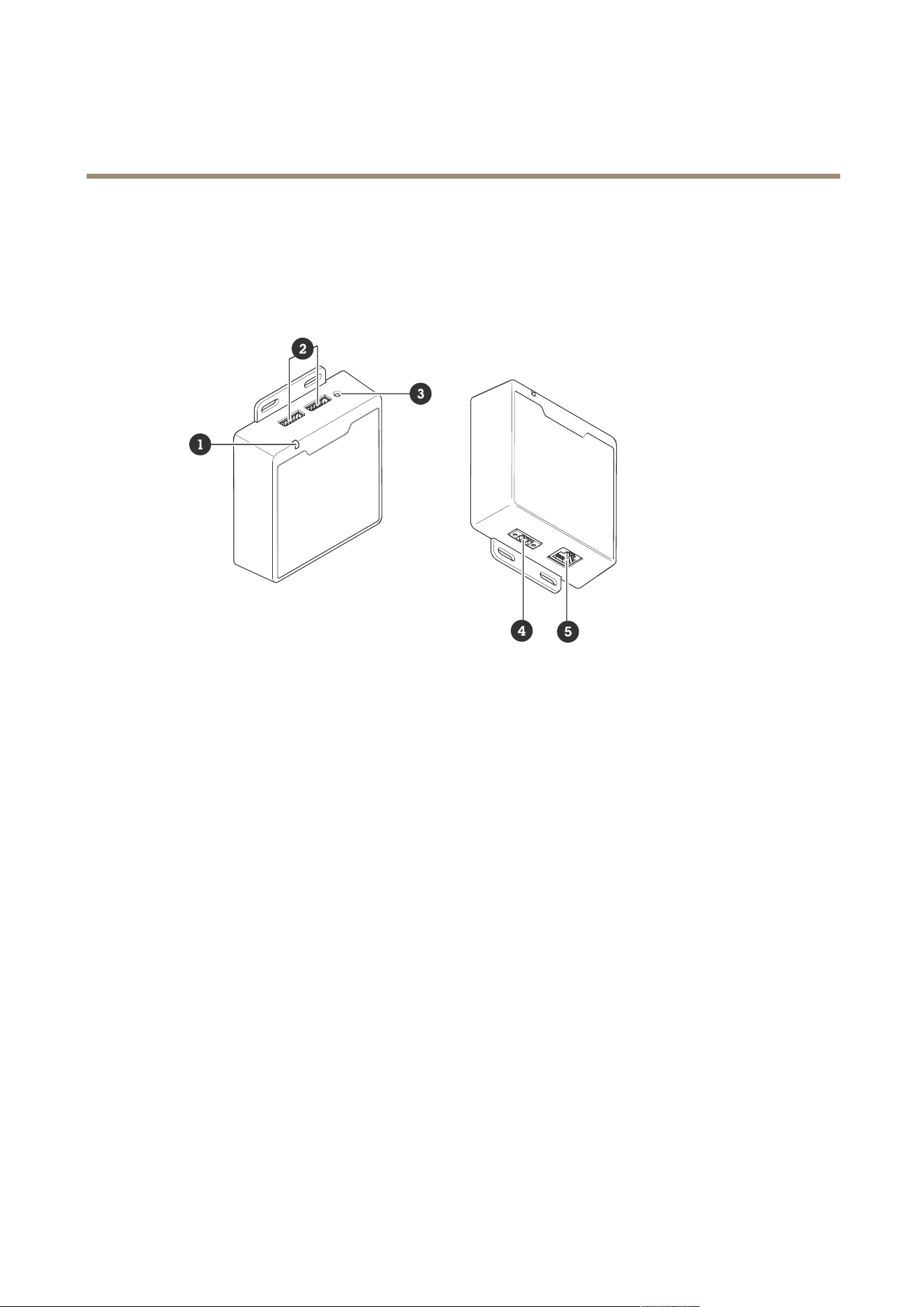
Product overview
1
Status LED
2
2x I/O connectors
3
Control button
4
P ower connector
5
RJ45 ethernet connector
Buttons
Control button
The control button is used for:
• Resetting the product to factory default settings. See Reset to factory default settings on page 34 .
• Connecting to a one - click cloud connection (O3C) service over the internet. T o connect, press and hold the button
for about 3 seconds until the status LED ashes green.
Connectors
Network connector
RJ45 Ethernet connector .
Input: RJ45 Ethernet connector with P ower over Ethernet (P oE).
Output: RJ45 Ethernet connector with P ower over Ethernet (P oE).
28
AXIS W401 Body W or n Activation Kit
Specifications
I/O connector
Use the I/O connector with external devices in combination with, for example, motion detection, event triggering, and alarm
notications. In addition to the 0 VDC reference point and power (12 V DC output), the I/O connector provides the interface to:
Digital input - For connecting devices that can toggle between an open and closed circuit, for example PIR sensors, door/window
contacts, and glass break detectors.
Supervised input - Enables possibility to detect tampering on a digital input.
Digital output - For connecting external devices such as relays and LEDs. Connected devices can be activated by the VAPIX®
Application Programming Interface, through an event or from the device’s web interface.
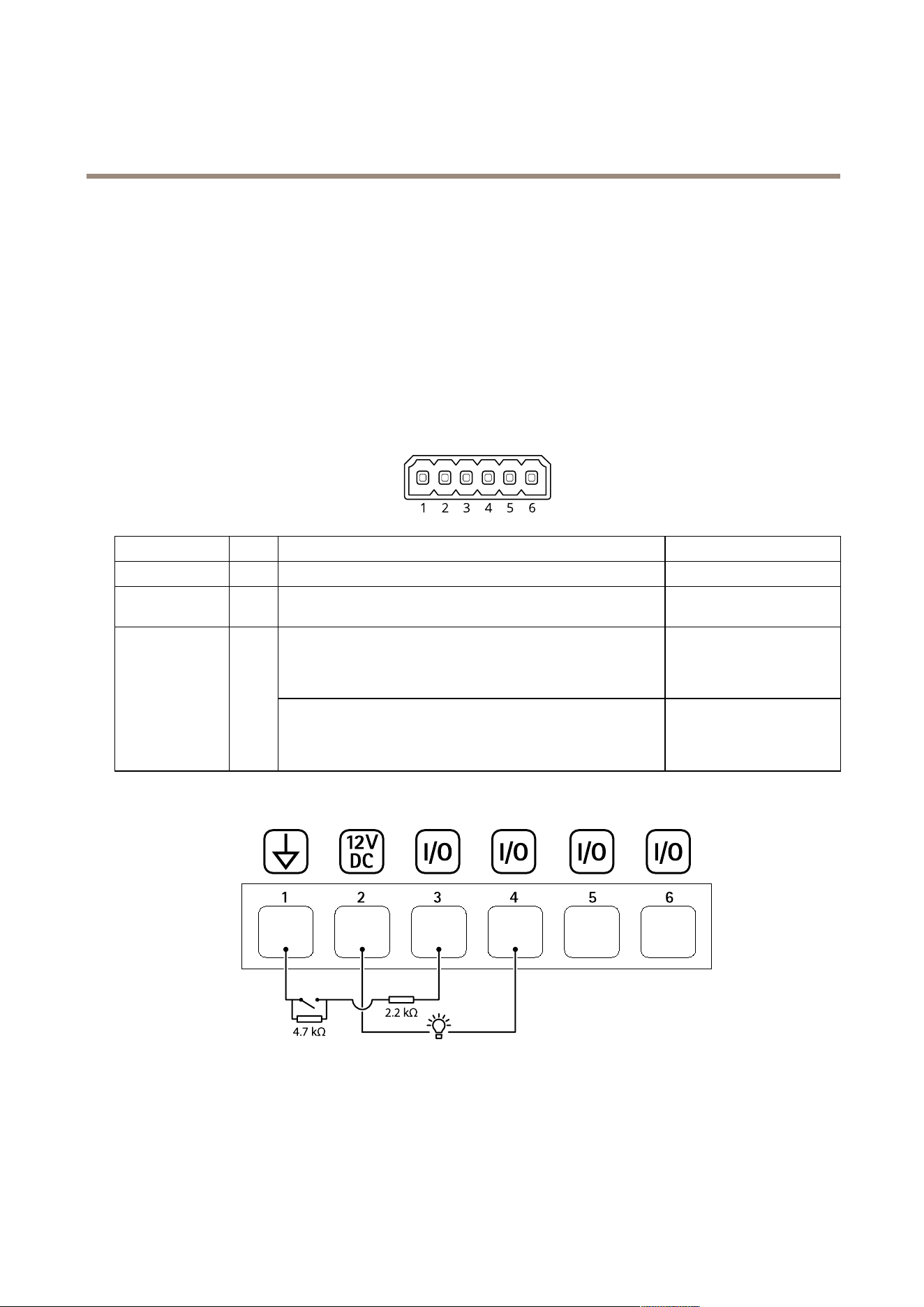
6 - pin terminal block
Function Pin Notes
Specications
DC ground
1
0 VDC
DC output
2
Can be used to power auxiliary equipment.
Note: This pin can only be used as power out.
12 VDC
Max load = 50 mA
Digital input or Supervised input – Connect to pin 1 to activate, or
leave oating (unconnected) to deactivate. T o use supervised input,
install end - of - line resistors. See connection diagram for information
about how to connect the resistors.
0 to max 30 VDCCongurable
(Input or Output)
3–6
Digital output – Internally connected to pin 1 (DC ground) when
active, and oating (unconnected) when inactive. If used with an
inductive load, e.g., a relay , connect a diode in parallel with the load,
to protect against voltage transients.
0 to max 30 VDC, open drain,
1 00 mA
Example:
1
DC ground
2
DC output 12 V, max 50 mA
3
I/O congured as supervised input
4
I/O congured as output
5
Congurable I/O
6
Congurable I/O
29

AXIS W401 Body W or n Activation Kit
Specifications
P ower connector
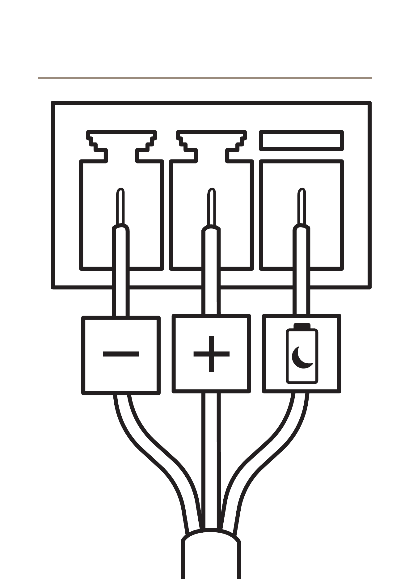
3 - pin terminal block for power input. Use a Safety Extra Low V oltage (SEL V) compliant limited power source (LPS) with either a rated
output power limited to ≤ 1 00 W or a rated output current limited to ≤ 5 A.
30
AXIS W401 Body W or n Activation Kit
Specifications
DC power input:
Delayed shutdown
Important
T o avoid unwanted shutdown, only turn on Delayed shutdown when the ignition is physically connected to the main unit.
3 1

AXIS W401 Body W or n Activation Kit
Specifications
Note
If the device has been without power before it is turned on, a delay occurs before Delayed shutdown is activated.
1. Connect to ignition control on the 3 - pin terminal block.
2. Go to the device’s web interface.
3. Go to System > P ower settings and turn on Delayed shutdown .
4. Set a delay time between 1 and 60 minutes.
32

AXIS W401 Body W or n Activation Kit
Configur e your system
Configur e your system
Receive bluetooth beacon signal
The following conguration explains how the AXIS Body W orn Activation Kit receives bluetooth beacon signal.
Congure the Body W orn Activation Kit
1. Go to System > Events and add a rule.
2. In the list of conditions, select Bluetooth beacon signal received .
3. In System ID , enter the body worn system’s ID. Y ou can nd it in the About menu in AXIS Body W orn Manager .
4. Select the port that the device is connected to.
5. In the list of actions, select one of the actions.
Congure the Body W orn System
1. Install the body worn system according to the Axis body worn solution user manual .
2. In AXIS Body W orn Manager , go to Camera proles and select the camera prole you want to use for the onboard system.
3. Under Recording activation , select Broadcast wireless signal .
Broadcast bluetooth beacon signal
The following conguration explains how the AXIS Body W orn Activation Kit broadcasts bluetooth beacon signal.
Congure the AXIS Body W orn Activation Kit
1. Congure the recording activation input:
1.1 Go to System > Accessories .
1.2 On the port where you connected the device, click to set the direction to input.
2. Create a rule:
2.1 Go to System > Events and add a rule.
2.2 In the list of conditions, select Digital input is active .
2.3 Select the port that the device is connected to.
2.4 In the list of actions, select Broadcast signal .
2.5 In System ID , enter the body worn system’s ID. Y ou can nd it in the About menu in AXIS Body W orn Manager .
2.6 In Message type , enter 1 to broadcast the message lightbar active .
Congure the Body W orn System
1. Install the body worn system according to the Axis body worn solution user manual .
2. In AXIS Body W orn Manager , go to Camera proles and select the camera prole you want to use for the onboard system.
3. Under Recording activation , select Receive wireless broadcast .
33

AXIS W401 Body W or n Activation Kit
T r oubleshooting
T r oubleshooting
Reset to factory default settings
Important
Reset to factory default should be used with caution. A reset to factory default resets all settings, including the IP address, to
the factory default values.
T o reset the product to the factory default settings:
1. Disconnect power from the product.
2. Press and hold the control button while reconnecting power . See Product overview on page 28 .
3. K eep the control button pressed for 15–30 seconds until the status LED indicator ashes amber .
4. Release the control button. The process is complete when the status LED indicator turns green. If no DHCP server is
available on the network, the device IP address will default to one of the following:
- Devices with AXIS OS 12.0 and later: Obtained from the link - local address subnet (169.254.0.0/16)
- Devices with AXIS OS 1 1.1 1 and earlier: 192.168.0.90/24
5. Use the installation and management software tools to assign an IP address, set the password, and access the device.
The installation and management software tools are available from the support pages on axis.com/support .
Y ou can also reset parameters to factory default through the device’s web interface. Go to Maintenance > Factory default and
click Default .
AXIS OS options
Axis offers device software management according to either the active track or the long - term support (L TS) tracks. Being on the
active track means continuously getting access to all the latest product features, while the L TS tracks provide a xed platform with
periodic releases focused mainly on bug xes and security updates.
Using AXIS OS from the active track is recommended if you want to access the newest features, or if you use Axis end - to - end system
offerings. The L TS tracks are recommended if you use third - party integrations, which are not continuously validated against the latest
active track. With L TS, the products can maintain cybersecurity without introducing any signicant functional changes or affecting
any existing integrations. For more detailed information about Axis device software strategy , go to axis.com/support/device - software .
Check the current AXIS OS version
AXIS OS determines the functionality of our devices. When you troubleshoot a problem, we recommend that you to start by checking
the current AXIS OS version. The latest version might contain a correction that xes your particular problem.
T o check the current AXIS OS version:
1. Go to the device’s web interface > Status .
2. Under Device info , see the AXIS OS version.
Upgrade AXIS OS
Important
• Precongured and customized settings are saved when you upgrade the device software (provided that the features are
available in the new AXIS OS) although this is not guaranteed by Axis Communications AB .
• Make sure the device remains connected to the power source throughout the upgrade process.
34

AXIS W401 Body W or n Activation Kit
T r oubleshooting
Note
When you upgrade the device with the latest AXIS OS version in the active track, the product receives the latest functionality
available. Always read the upgrade instructions and release notes available with each new release before you upgrade. T o
nd the latest AXIS OS version and the release notes, go to axis.com/support/device - software .
1. Download the AXIS OS le to your computer , available free of charge at axis.com/support/device - software .
2. Log in to the device as an administrator .
3. Go to Maintenance > AXIS OS upgrade and click Upgrade .
When the upgrade has nished, the product restarts automatically .
T echnical issues , clues , and solutions
If you can’t nd what you’re looking for here, try the troubleshooting section at axis.com/support .
Problems upgrading AXIS OS
AXIS OS upgrade failure
If the upgrade fails, the device reloads the previous version. The
most common reason is that the wrong AXIS OS le has been
uploaded. Check that the name of the AXIS OS le corresponds
to your device and try again.
Problems after AXIS OS upgrade
If you experience problems after the upgrade, roll back to the
previously installed version from the Maintenance page.
Problems setting the IP address
The device is located on a
different subnet
If the IP address intended for the device and the IP address of the computer used to access the
device are located on different subnets, you cannot set the IP address. Contact your network
administrator to obtain an IP address.
The IP address is being used
by another device
Disconnect the Axis device from the network. Run the ping command (in a Command/DOS window ,
type ping and the IP address of the device):
• If you receive: Reply from <IP address>: bytes=32; time=10...
this means that the IP address may already be in use by another device on the network.
Obtain a new IP address from the network administrator and reinstall the device.
• If you receive: Request timed out , this means that the IP address is available
for use with the Axis device. Check all cabling and reinstall the device.
P ossible IP address conict
with another device on the
same subnet
The static IP address in the Axis device is used before the DHCP server sets a dynamic address.
This means that if the same default static IP address is also used by another device, there may
be problems accessing the device.
The device can’t be accessed from a browser
Can’t log in
When HTTPS is enabled, ensure that the correct protocol (HTTP or HTTPS) is used when attempting
to log in. Y ou may need to manually type http or https in the browser’s address eld.If the
password for the root account is lost, the device must be reset to the factory default settings. See
Reset to factory default settings on page 34 .
The IP address has been
changed by DHCP
IP addresses obtained from a DHCP server are dynamic and may change. If the IP address has been
changed, use AXIS IP Utility or AXIS Device Manager to locate the device on the network. Identify
the device using its model or serial number , or by the DNS name (if the name has been congured).If
required, a static IP address can be assigned manually . For instructions, go to axis.com/support .
Certicate error when using
IEEE 80 2.1X
For authentication to work properly , the date and time settings in the Axis device must be
synchronized with an NTP server . Go to System > Date and time .
35

AXIS W401 Body W or n Activation Kit
T r oubleshooting
The device is accessible locally but not externally
T o access the device externally , we recommend you to use one of the following applications for Windows
®
:
• AXIS Camera Station Edge: free of charge, ideal for small systems with basic surveillance needs.
• AXIS Camera Station 5: 30 - day trial version free of charge, ideal for small to mid - size systems.
• AXIS Camera Station Pro: 90 - day trial version free of charge, ideal for small to mid - size systems.
For instructions and download, go to axis.com/vms .
Can’t connect over port 8883 with MQTT over SSL
The rewall blocks trafc
using port 8883 as it’s
deemed insecure.
In some cases the server/broker might not provide a specic port for MQTT communication. It may
still be possible to use MQTT over a port normally used for HTTP/HTTPS trafc.
• If the server/broker supports W ebSocket/W ebSocket Secure (WS/WSS), typically on
port 443, use this protocol instead. Check with the server/broker provider to see if
WS/WSS is supported and which port and basepath to use.
• If the server/broker supports ALPN, the use of MQTT can be negotiated over an open
port, such as 443. Check with your server/broker provider to see if ALPN is supported
and which ALPN protocol and port to use.
Contact support
If you need more help, go to axis.com/support .
36

User manual V er . M3.2
AXIS W40 1 Body W orn Activation Kit
Date: March 20 25
© Axis Communications AB, 20 25
P art no. T1 0 220834