www.lg.com
OWNER’S MANUAL
COMMERCIAL
WASHER
Copyright © 2023 LG Electronics Inc. All Rights Reserved
CWG27MDQHS CWG27MDOHS CWG27MDCHS CWG27MSQHS
CWG27MSOHS CWG27MSCHS
MFL71671268
Rev.00_022323
ENGLISH
Before beginning installation, read these instructions carefully. This will
simplify installation and ensure that the washer is installed correctly
and safely. Leave these instructions near the washer after installation
for future reference.

2
PRODUCT FEATURES
PRODUCT FEATURES
DIRECT DRIVE SYSTEM
The advanced brushless DC motor drives the drum directly without using a belt and pulley.
TILTED DRUM AND EXTRA LARGE DOOR OPENING
The tilted drum and extra large opening make it possible to load and unload clothing more easily.
ULTRA CAPACITY
The larger drum enables more tumbling action and greater centrifugal force, but also less tangling and wrinkling of the
laundry. Heavier loads, such as king size comforters, blankets, and curtains can be washed.
SEE-THROUGH DOOR AND BIG DOOR
You can see the laundry throughout the cycle.
MAGNETIC DOOR PLUNGER
Safely and conveniently secure the door slightly ajar with the magnetic door plunger. This will promote air circulation
and allow the interior of the machine to dry. To use this feature, after the load has been removed, do not close the door
completely. When the magnetic door plunger comes into contact with the metal washer cabinet, it will secure the door
slightly open allowing the interior of the washer to dry.
STAINLESS STEEL DRUM
Stainless steel drum offers extreme durability.
TUB CLEAN
Regular cleaning of the tub on a monthly basis using TUB CLEAN can help keep the tub clean and fresh.
Laundry Lounge Apps
− Laundry Lounge Installer : This is a registration app for installers used to register the product on
the server. Only available for authorized users.
* Search for Laundry Lounge Installer in the Google Play Store or Apple App Store.
− Laundry Lounge : This is for end-users to check real-time monitoring of registered stores and
products.
* Search for Laundry Lounge in the Google Play Store or Apple App Store.
3
SAFETY INSTRUCTIONS
HEATER
SAFETY INSTRUCTIONS
READ ALL INSTRUCTIONS BEFORE USE
The following safety guidelines are intended to prevent unforeseen risks
or damage from unsafe or incorrect operation of the appliance.
The guidelines are separated into ‘WARNING’ and ‘CAUTION’ as
described below.
Safety Messages
This symbol is displayed to indicate matters and operations
that can cause risk. Read the part with this symbol carefully
and follow the instructions in order to avoid risk.
WARNING
This indicates that the failure to follow the instructions can
cause serious injury or death.
CAUTION
This indicates that the failure to follow the instructions can
cause the minor injury or damage to the product.
4
SAFETY INSTRUCTIONS
WARNING
To reduce the risk of explosion, fire, death, electric shock, injury or
scalding to persons when using this product, follow basic precautions,
including the following:
Technical Safety
• This appliance is not intended for use by persons (including children)
with reduced physical, sensory or mental capabilities, or lack of
experience and knowledge, unless they have been given supervision
or instruction concerning use of the appliance by a person
responsible for their safety.
This appliance can be used by children aged from 8 years and
above and persons with reduced physical, sensory or mental
capabilities or lack of experience and knowledge if they have been
given supervision or instruction concerning use of the appliance in
a safe way and understand the hazards involved. Children shall not
play with the appliance. Cleaning and user maintenance shall not be
made by children without supervision.
Children of less than 3 years should be kept away unless
continuously supervised.

5
SAFETY INSTRUCTIONS
HEATER
• Children should be supervised to ensure that they do not play with
the appliance.
• If the power cord is damaged, it must be replaced by the
manufacturer, its service agent or similarly qualified persons in order
to avoid a hazard.
• Use a new hose or hose-set supplied with the appliance. Reusing old
hoses can cause a water leak and subsequent property damage.
• Ventilation openings must not be obstructed by a carpet.
• The inlet water pressure must be between 100 kPa and 1000 kPa.
Maximum Capacity
• The maximum capacity in some cycles for dry clothes to be washed
is 10.5 kg.
Installation
• Never attempt to operate the appliance if it is damaged,
malfunctioning, partially disassembled, or has missing or broken
parts, including a damaged cord or plug.
• This appliance should only be transported by two or more people
holding the appliance securely.
• Do not install the appliance in a damp and dusty place. Do not
install or store the appliance in any outdoor area, or any area that is
subject to weathering conditions such as direct sunlight, wind, rain, or
temperatures below freezing.
• Do not install the product in a laundry factory environment.
• This appliance is not designed for maritime use or for mobile
installations such as in RVs, aircraft, etc.
• Make sure the power plug is completely pushed into the power outlet.
• Do not plug the appliance into multiple outlet sockets, power boards,
or an extension power cable.
• Do not modify the power plug provided with the appliance. If it does
not fit the power outlet, have a proper outlet installed by a qualified
electrician.

6
SAFETY INSTRUCTIONS
• This appliance is equipped with a power cord having an
equipmentearthing / grounding conductor (earthing pin) and a
grounding power plug. The power plug must be plugged into an
appropriate outlet socket that is installed and earthed / grounded in
accordance with all local codes and ordinances.
• Improper connection of the equipment-grounding conductor can
result in risk of electric shock. Check with a qualified electrician or
service personnel if you are in doubt as to whether the appliance is
properly grounded.
• This appliance must not be installed behind a lockable door, a
sliding door or a door with a hinge on the opposite side to that of the
appliance, in such a way that a full opening of the appliance door is
restricted.
Operation
• Do not apply any sharp objects to the control panel in order to
operate the appliance.
• Do not attempt to separate any panels or disassemble the appliance.
• Do not repair or replace any part of the appliance. All repairs
and servicing must be performed by qualified service personnel
unless specifically recommended in this Owner’s Manual. Use only
authorized factory parts.
• Do not push down the door excessively, when the appliance door is
open.
• Do not put animals, such as pets into the appliance.
• Do not wash rugs, mats, shoes or pet blankets, stuffed toys, or any
other items other than clothes or sheets, in this machine.
• Keep the area underneath and around the appliance free of
combustible materials such as lint, paper, rags, chemicals, etc.
• Do not leave the appliance door open. Children may hang on the
door or crawl inside the appliance, causing damage or injury.

7
SAFETY INSTRUCTIONS
HEATER
• Do not put in, wash or dry articles that have been cleaned in, washed
in, soaked in, or spotted with combustible or explosive substances
(such as waxes, wax removers, oil, paint, gasoline, degreasers,
drycleaning solvents, kerosene, petrol, spot removers, turpentine,
vegetable oil, cooking oil, acetone, alcohol, etc.). Improper use can
cause fire or explosion.
• Do not use or store flammable or combustible substances (ether,
benzene, alcohol, chemical, LPG, combustible spray, gasoline,
thinner, petroleum, insecticide, air freshener, cosmetics, etc.) near the
appliance.
• Never reach into the appliance while it is operating. Wait until the
drum has completely stopped.
• Do not touch the door during a high temperature programme.
• Turn off water taps to relieve pressure on hoses and valves and
to minimize leakage if a break or rupture should occur. Check the
condition of the fill hoses; they should be replaced after 5 years.
• If there is a gas leakage (isobutane, propane, natural gas, etc.)
within the launderette, do not touch the appliance or power plug and
ventilate the area immediately.
• If the drain hose or inlet hose is frozen during winter, use it only after
thawing.
• Keep all washing detergents, softener and bleach away from children.
• Do not touch the power plug or the appliance controls with wet hands.
• Do not bend the power cable excessively or place a heavy object on
it.
• Avoid touching any water that is drained from the appliance during
the wash.
• Make sure that drainage is working properly. If water is not drained
properly, your floor may get flooded.
• When the air temperature is high and the water temperature is low,
condensation may occur and thus wet the floor.
• Wipe off dirt or dust on the contacts of the power plug.

8
SAFETY INSTRUCTIONS
Maintenance
• Disconnect the appliance from the power supply before cleaning the
appliance. Setting the controls to the OFF or stand by position does
not disconnect this appliance from the power supply.
• Securely plug the power plug in the outlet socket after completely
removing any moisture and dust.
• Do not spray water inside or outside the appliance to clean it.
• Never unplug the appliance by pulling on the power cable. Always
grip the power plug firmly and pull straight out from the outlet socket.
• Do not repair or replace any part of the appliance or attempt any
servicing unless specifically recommended in the user-maintenance
instructions or published user-repair instructions that you understand
and have the skills to carry out.
Disposal
• Before discarding an old appliance, unplug it. Cut off the cable
directly behind the appliance to prevent misuse.
• Dispose of all packaging materials (such as plastic bags and
styrofoam) away from children. The packaging materials can cause
suffocation.
• Remove the door before disposing of or discarding this appliance to
avoid the danger of children or small animals getting trapped inside.
9
SAFETY INSTRUCTIONS
HEATER
CARING FOR THE ENVIRONMENT
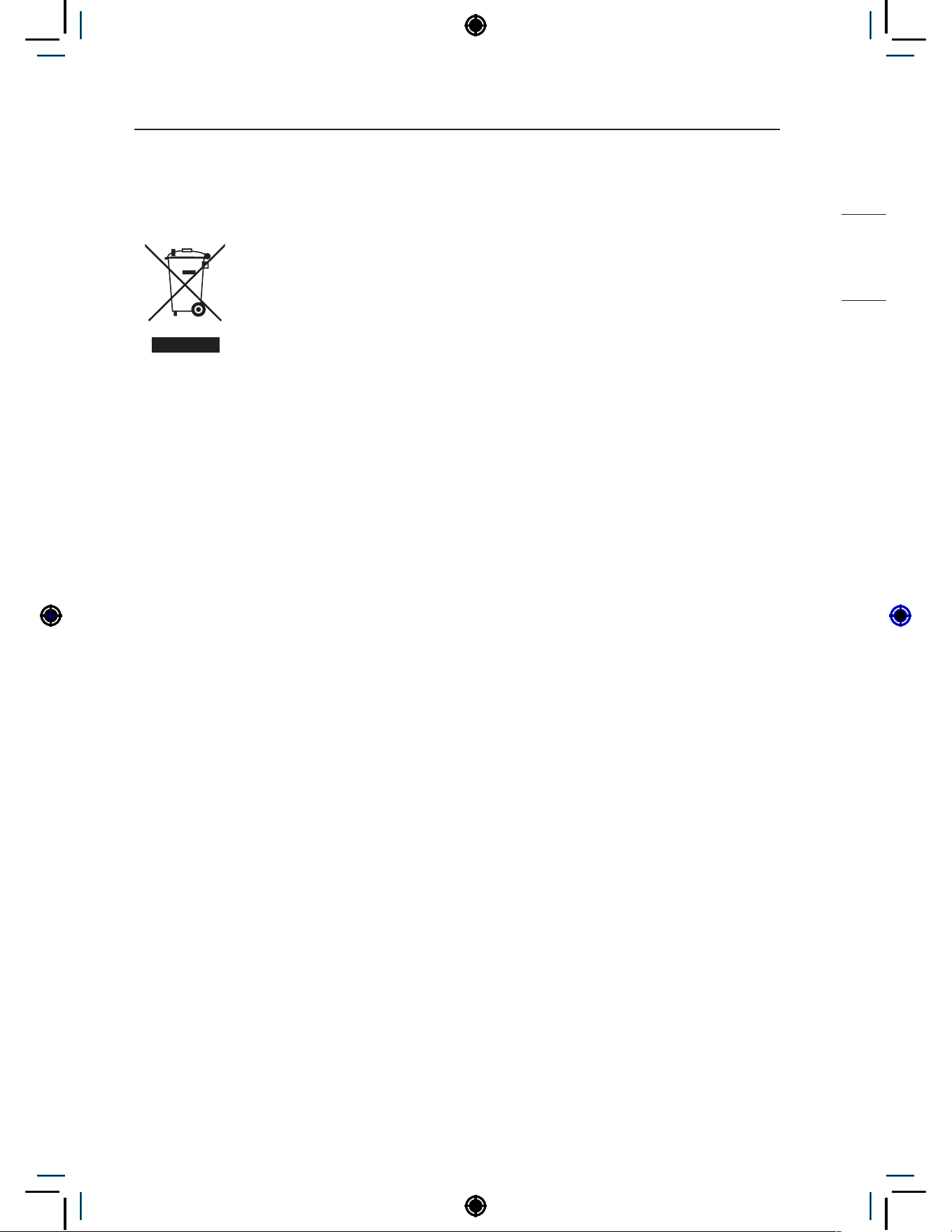
Disposal of Your Old Appliance
• When this crossed out wheeled bin symbol is depicted on
the product and its operator’s manual, it means the product
is covered by the e-waste Management and Handling
Rules, 2011 and are meant to be recycled, dismantled,
refurbished or disposed off.
• Do’s
− a. The product is required to be handed over only to the authorized
recycler for disposal.
− b. Keep the product in isolated area, after it becomes non-functional/
unrepairable so as to prevent its accidental breakage.
• Don’ts
− a. The product should not be opened by the user himself/herself, but
only by authorized service personnel.
− b. The product is not meant for re-sale to any unauthorized
agencies/scrap dealer/kabariwalah.
− c. The product is not meant for mixing into household waste stream.
− d. Do not keep any replaced spare part(s) from the product in
exposed area.
• Any disposal through unauthorized agencies/person will attract action
under Environment (Protection) Act 1986.
• This product is complied with the requirement of Hazardous
Substances as specified under E-Waste Management Rules India
published by MoEF & CC, Govt. of India.
• To locate a nearest collection centre or call for pick-up (limited area
only) for disposal of this appliance, please contact No. 08069379999,
Toll Free No. 1800-315-9999 for details. All collection centre and pick
up facilities are done by third parties with LG Electronics India Pvt.
Ltd. Merely as a facilitator. For more detailed information, please visit
: http://www.lg.com/in.

TABLE OF CONTENTS
PRODUCT FEATURES ...................................................................2
SAFETY INSTRUCTIONS ..............................................................3
READ ALL INSTRUCTIONS BEFORE USE .....................................................3
CARING FOR THE ENVIRONMENT ................................................................9
PARTS AND ACCESSORIES .......................................................12
Parts ................................................................................................................12
Accessories .....................................................................................................12
CONTROL PANEL FEATURES ....................................................13
Coin type .........................................................................................................13
OPL type .........................................................................................................13
Card type.........................................................................................................14
INSTALLATION INSTRUCTIONS .................................................16
Checking and choosing the proper location ....................................................16
Unpacking and removing shipping bolts .........................................................17
Connecting the water lines ..............................................................................18
Connecting the drain line ................................................................................19
Leveling the washing machine ........................................................................20
PREPARATION .............................................................................21
Precautions for fabric care before wash cycle ................................................21
Fabric care labels ............................................................................................22
Sorting laundry ................................................................................................22
How to wash better .........................................................................................22
Laundry loading guide .....................................................................................23
About the dispenser ........................................................................................23
Loading the dispenser .....................................................................................24
OPERATING YOUR WASHER .....................................................25
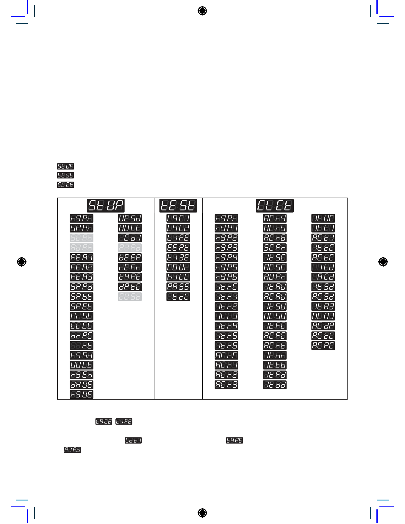
PROGRAMMING MODE ...............................................................26
Structure of Programming mode – Coin type ..................................................27
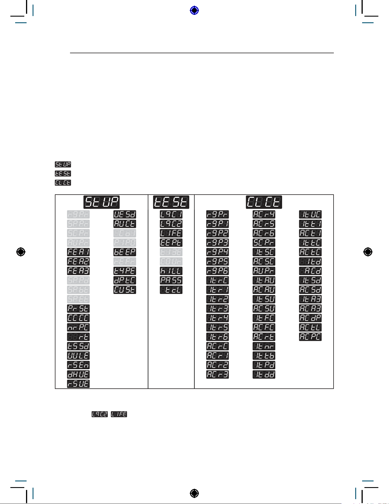
Structure of Programming mode – OPL type ..................................................28
PROGRAMING MODE – SETUP MODE ......................................29
Setup Mode :
(display) .......................................................................29
PROGRAMING MODE – TEST MODE .........................................83
This manual may contain images or content
different from the model you purchased.
This manual is subject to revision by the
manufacturer.
Diagnostic tests: (display) .....................................................................83
PROGRAMING MODE – COLLECT MODE .................................89
Collect information data : (display) .....................................................89
Collect Mode Data lists ...................................................................................89
SMART FUNCTIONS ....................................................................91
Open Source Software Notice Information......................................................91
MAINTENANCE ............................................................................92
Care after wash ...............................................................................................92
ERROR MODE ..............................................................................96
POWER FAIL RECOVERY ...........................................................97
DEFAULT WASHER SETTINGS ..................................................97
SPECIFICATIONS .........................................................................97
WIRING DIAGRAM .......................................................................98
12
PARTS AND ACCESSORIES
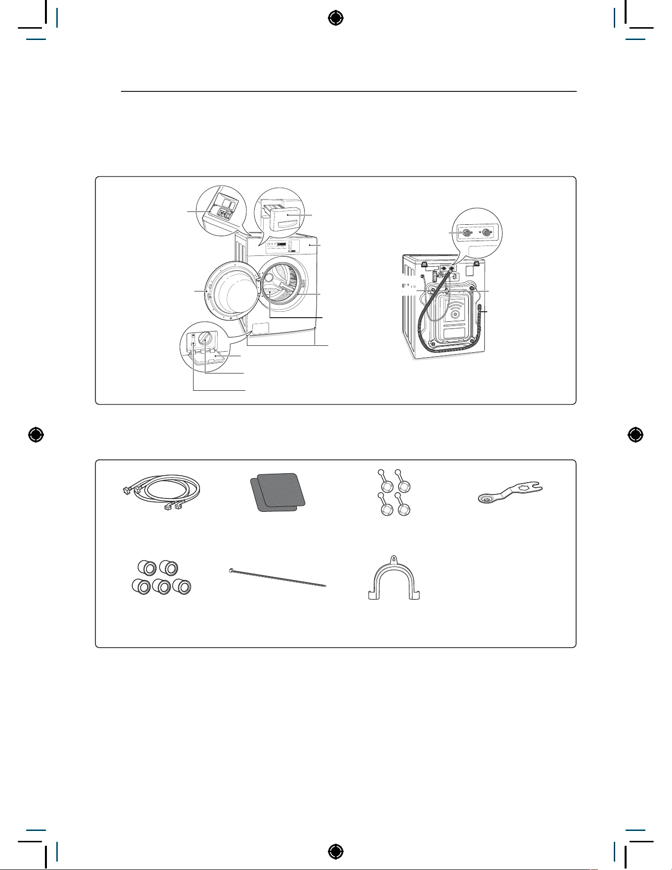
PARTS AND ACCESSORIES
Parts
Detergent
dispenser
(for single
model)
Detergent dispenser
drawer (for stack
model)
Control
panel
Power cord
Drain hose
Door seal
Tub
Leveling feet
Drain pump filter cover
Drain pump filter
Drain hose
Door Magnet
Door Plunger
(see page 2)
Water
inlets
Shipping
bolts
Accessories
Hot and Cold Water
Hoses
Non-skid pads
Caps (4) (for covering
shipping bolt holes)
Wrench (for removing
shipping bolts and
adjusting leveling feet)
Hole cap (5) (for
securing auto dosing
hole)
Tie Strap (for securing
drain hose)
Elbow Bracket (for
securing drain hose)
13
CONTROL PANEL FEATURES
HEATER
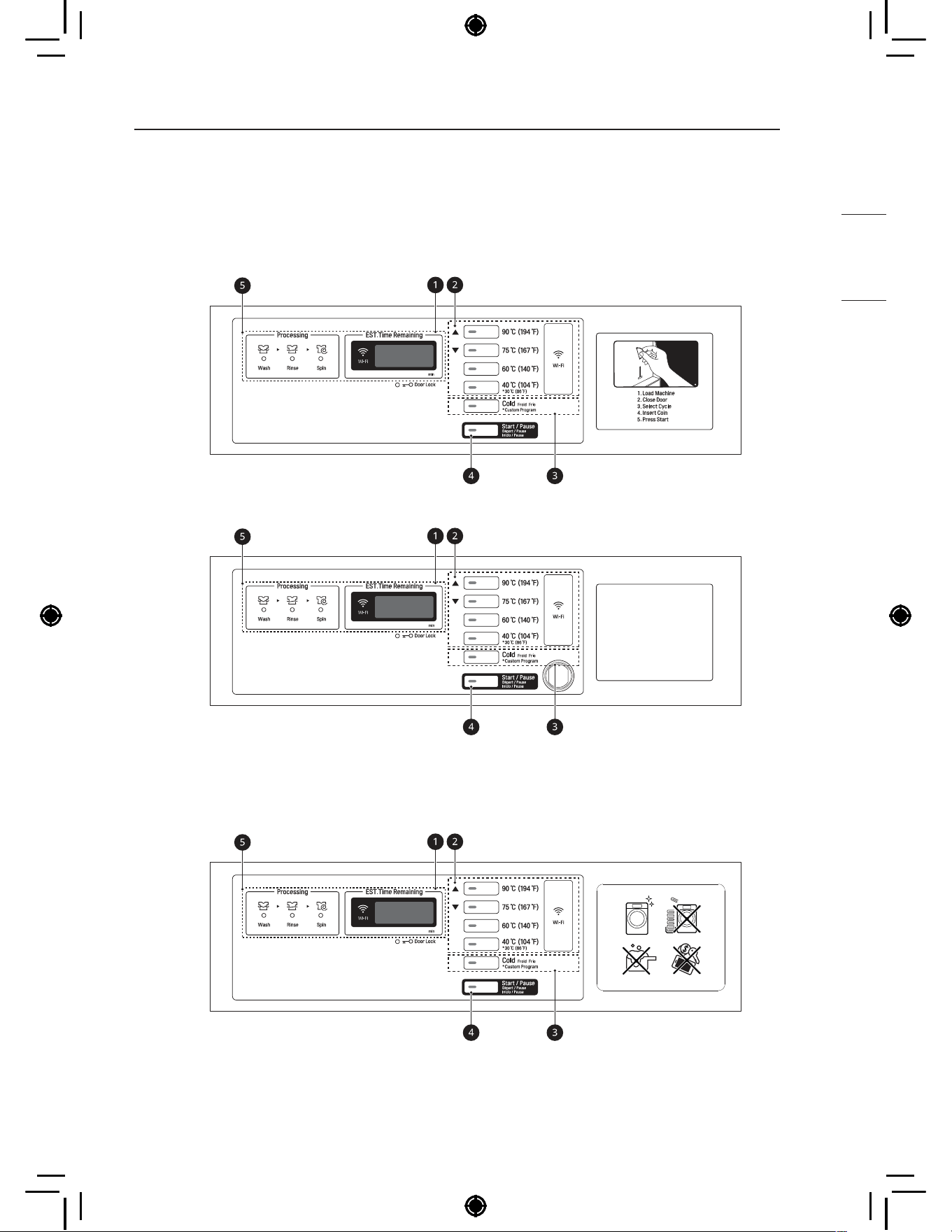
CONTROL PANEL FEATURES
Coin type
- Side by side(CWG27MSQHS)
- Stack(CWG27MDQHS)
OPL type
- Side by side(CWG27MSOHS)
- Stack(CWG27MDOHS)
14
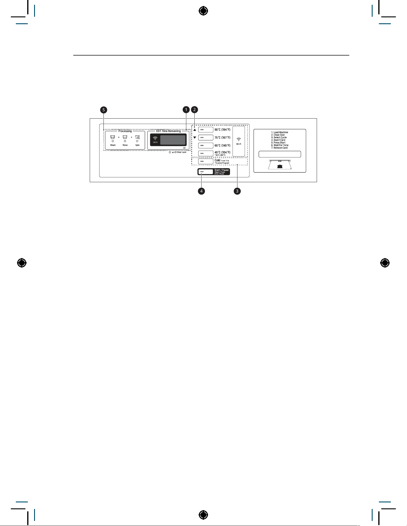
CONTROL PANEL FEATURES
Card type
- Side by side (CWG27MSCRS)
- Stack (CWG27MDCRS)
a
Display LED
b
Cycle button
c
Optional function button
d
Start/Pause button
e
Status LED
15
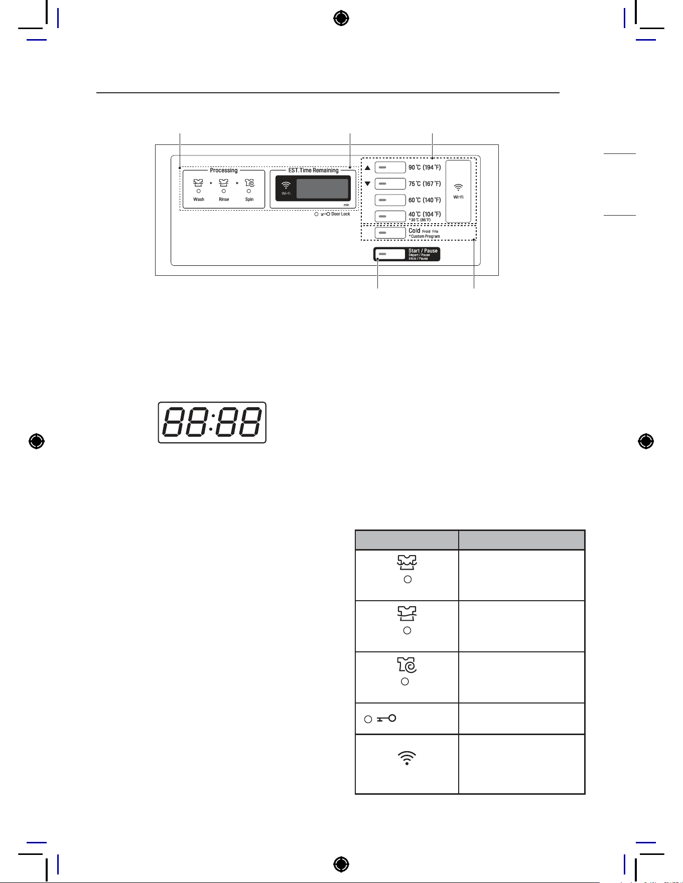
CONTROL PANEL FEATURES
HEATER
Display LED
The display shows the vend price and remaining
time and programming options. Error codes are
also displayed here.
Cycle Buttons
Press the CYCLE buttons to select the desired
cycle based on laundry types and conditions.
90°C (194°F)
Use it for the more medical wash than 75°C
(167°F) such as white clothes, baby clothes,
sheets and underwear.
75°C (167°F)
Use it for heavy soiled fabrics such as white
clothes, baby clothes, sheet and underwear.
60°C (140°F)
Use it for heavy soiled fabrics such as baby wear,
underwear and white clothes.
40°C (104°F) / 30°C (86°F)
Use it for normal soiled fabrics such as cotton,
linen, towels, shirts and jeans.
Cold
Use for cold washing for sturdy fabrics, such as
casual work.
Optional function button
Custom Program: Customized cycle program can
be used. Only available in OPL type.
Start/Pause button
The Start/Pause LED flashes when the full vend
price has been satisfied and the cycle has been
chosen.
Status LED
LED Description
Wash
LED flashes whenever
the Washing cycle is in
operation.
Rinse
LED flashes whenever
the Rinsing cycle is in
operation.
Spin
LED flashes whenever
the Spinning cycle is in
operation.
Door Lock
LED flashes whenever
the door lock is activated.
Wi-Fi
LED flashes when the
Wi-Fi is connecting.
LED stays lit when the
Wi-Fi is connected.
Cycle button
Start/Pause button Optional function button
Display LEDStatus LED

16
INSTALLATION INSTRUCTIONS
INSTALLATION INSTRUCTIONS
Checking and choosing
the proper location
Install the washing machine on a solid concrete
cement that is strong and rigid enough to support
the weight of the washing machine, even when
fully loaded, without flexing or bouncing. If the floor
has too much flex, you may need to reinforce it to
make it more rigid. If the floor is not solid, it may
cause severe vibration and noise.
1
Clean the floor before installation.
− Make sure to select solid and smooth
ground.
2
Two or more people are needed for moving
and unpacking the washing machine.
3
Allow for sufficient space between the walls
and the washing machine for installation.
Space requirements
You must allow sufficient space for water lines, the
drain line, and airflow.
NOTE
• Be sure to allow for wall, door, or floor moldings
that may increase the required clearances.
WARNING
• Certain internal parts are intentionally
not grounded and may present a risk of
electric shock only during servicing. Service
personnel - Do not contact the following
parts while the appliance is energized:
pump, valve, motor, control board.
Installing on a floor
77 cm
10 cm
139.6 cm
62.6 cm
98.3 cm
2.5 cm 2.5 cm
70 cm
NOTE
• The floor must be strong and rigid enough to
support the weight of the washer, when fully
loaded, without flexing or bouncing. If your floor
has too much flex, you may need to reinforce
it to make it more rigid. A floor that is adequate
for a top-loading washer may not be rigid
enough for a front loading washer, due to the
difference in the spin speed and direction. If the
floor is not solid, your washer may vibrate and
you may hear and feel the vibration throughout
your house.
• Before installing the washer, make sure the
floor is clean, dry and free of dust, dirt, water
and oils so the washer feet can not slide easily.
Leveling feet that can move or slide on the floor
can contribute to excess vibration and noise
due to poor contact with the floor.
17
INSTALLATION INSTRUCTIONS
HEATER
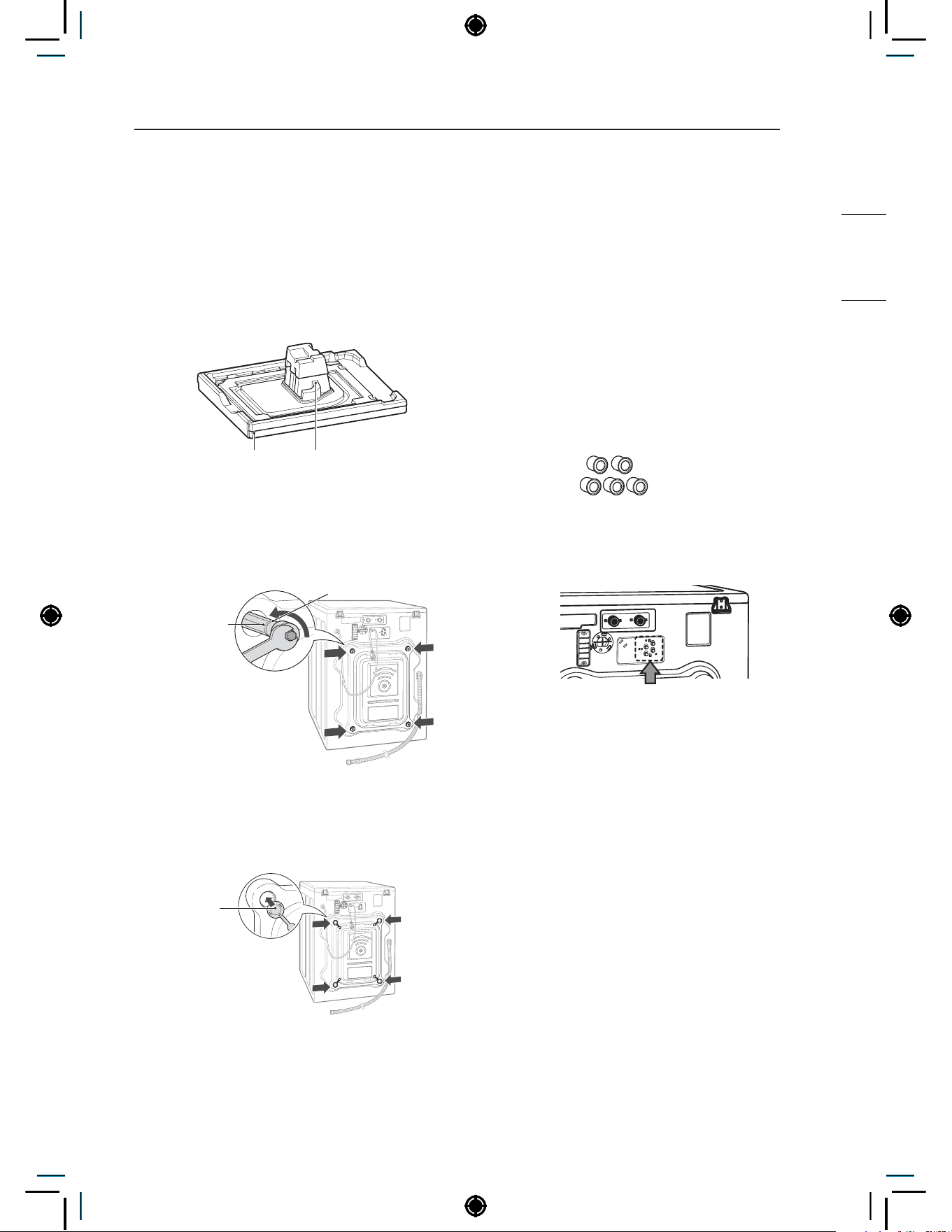
Unpacking and removing
shipping bolts
When removing the washer from the carton
base, be sure to remove the foam drum support
in the middle of the carton base. If you must lay
the washer down to remove the base packaging
materials, always lay it carefully on its side.
DO NOT lay the washer on its front or back.
Carton Base Foam Tub Support
1
Remove the bottom two shipping bolts
with the wrench (included) to fully loosen
all four shipping bolts by turning them
counterclockwise and then pulling them out.
Shipping
bolt
Retainer
2
Locate the four hole caps included in the
accessory pack and install them in the
shipping bolt holes.
Cap
NOTE
• Save the bolt assemblies for future use. To
prevent damage to internal components, DO
NOT transport the washer without reinstalling
the shipping bolts.
• Failure to remove shipping bolts and retainers
may cause severe vibration and noise, which
can lead to permanent damage to the washer.
The cord is secured to the back of the washer
with a shipping bolt to help prevent operation
with shipping bolts in place.
Installing Hole cap
1
Take the hole cap out from manual bag.
Hole cap
2
Insert the hole cap (4 pieces) into hose
connect in back of the machine.
NOTE
• In case of using auto dosing feature, inserting
hole cap is unnecessary.
18
INSTALLATION INSTRUCTIONS
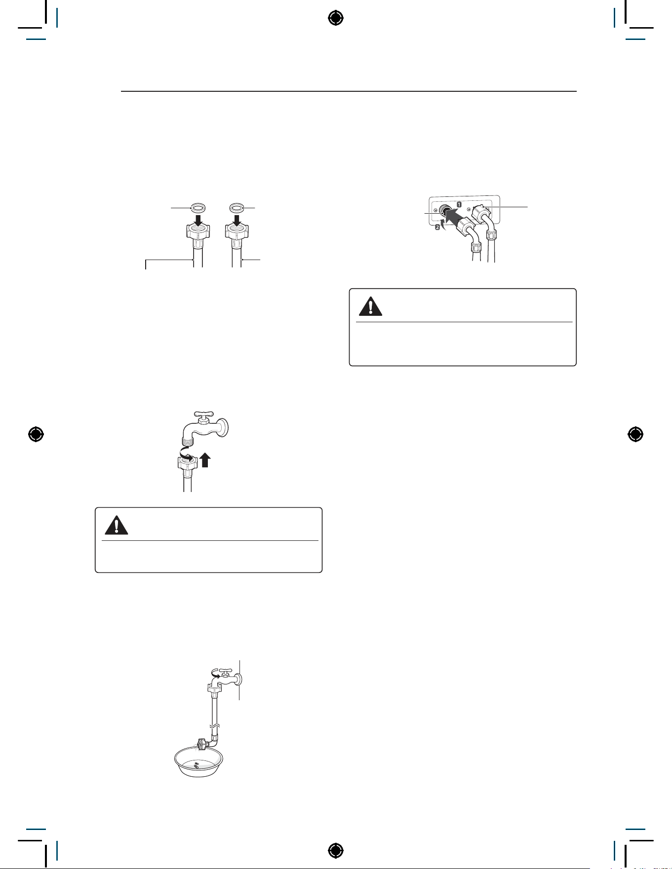
Connecting the water lines
1
Check the rubber seals on both sides of the
hose.
− Insert a rubber seal into the threaded fittings
on each hose to prevent leaking.
2
Connect the water supply hoses to the HOT
and COLD water faucets tightly by hand and
then tighten another 2/3 turn with pliers.
− Connect the blue hose to a cold water
faucet and the red hose to a hot water
faucet.
WARNING
• Do not overtighten. Damage to the
coupling can result.
3
After connecting inlet hose to water faucets,
turn on the water faucets to flush out foreign
substances (dirt, sand, sawdust) in the water
lines. Let water drain into a bucket, and check
the water temperature.
4
Connect the hoses to the water inlets tightly
by hand and then tighten another 2/3 turn with
pliers.
− Connect the blue hose to the cold water
inlet and the red hose to the hot water inlet.
WARNING
• Do not overtighten the hoses.
Overtightening can damage the valves
resulting in leaking and property damage.
5
Check for leaks by turning on the faucets.
− If water leaks, check steps 1 to 4 again.
NOTE
• For your safety, and for extended product
life, use only authorized components. The
manufacturer is not responsible for product
malfunction or accidents caused by the use of
separately purchased unauthorized parts.
• Use new hoses when you install the washing
machine. Do not reuse old hoses. Use only the
inlet hoses provided with the washer. LG does
not recommend the use of aftermarket hoses.
• Periodically check the hoses for cracks, leaks
and wear, and replace the hoses every 5 years.
• Do not stretch the water hoses intentionally,
and make sure that they are not crushed by
other objects.
• Water supply pressure must be between 1,0
kgf/cm² and 10,0 kgf/cm² (100~1000 KPa). If
the water supply pressure is more than 10,0
kgf/cm², a pressure reducing valve must be
installed.
• To provide optimum washing performance the
hot water temperature should be set at 120-
135°F (48-57°C) and the cold at 60°F (15°C).
Cold
water
inlet
Hot water
inlet
Water hose (To water
inlet on the washing
machine)
Rubber seal
Water hose
(To faucet)
Rubber seal
19
INSTALLATION INSTRUCTIONS
HEATER
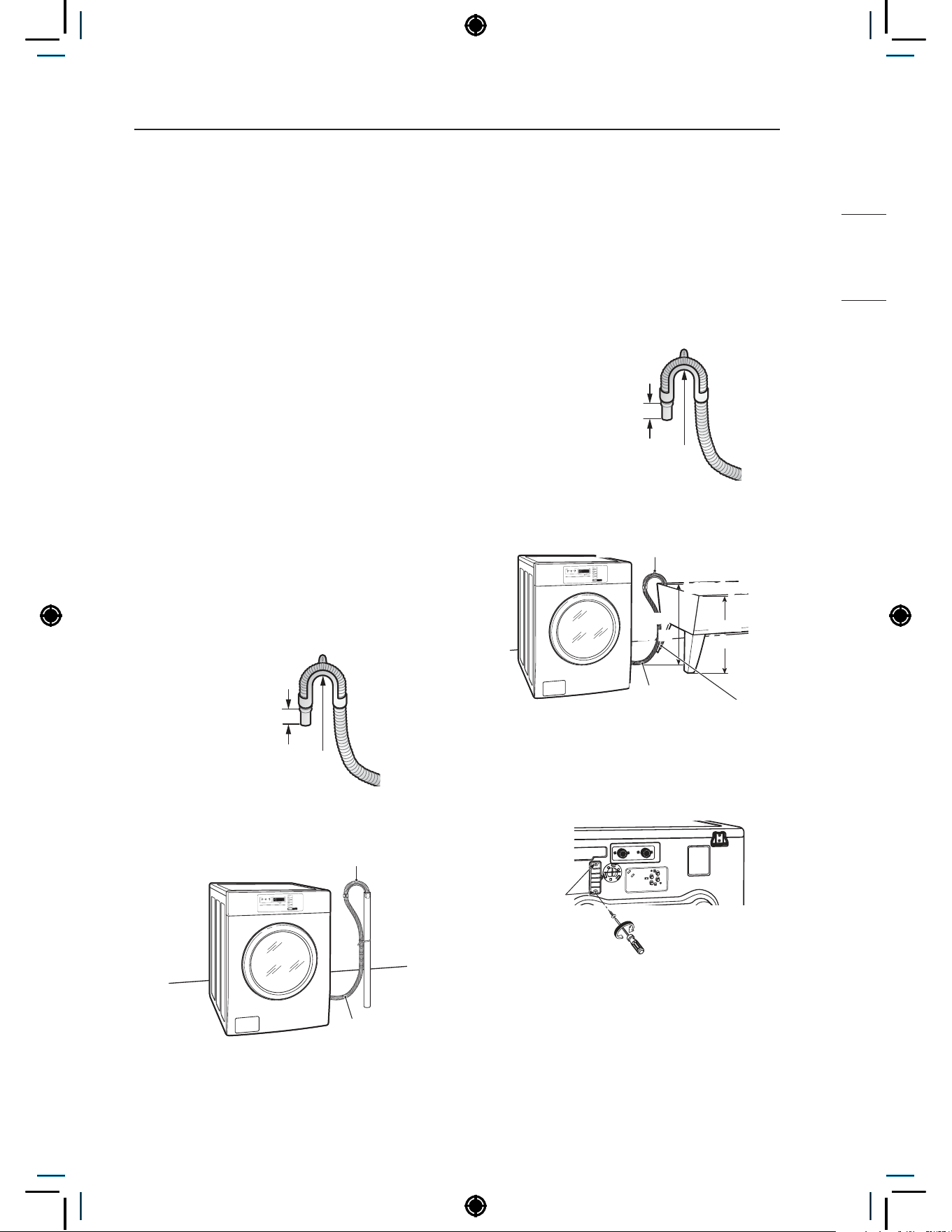
Connecting the drain line
Secure the drain hose in place to prevent moving
and leaking.
NOTE
• The drain hose should be properly secured.
Failure to properly secure the drain hose can
result in flooding and malfunction.
• Total height of the hose end should not exceed
100.0 cm from the bottom of the washer.
• The drain must be installed in accordance with
any applicable local codes and regulations.
• Make sure that the water lines are not
stretched, pinched, crushed, or kinked.
Using a standpipe
1
Clip the end of the hose into the elbow
bracket.
− Connect the elbow bracket within 10 cm
from the end of the drain hose. If the drain
hose is extended more than 10 cm beyond
the end of the elbow bracket, mold or
microorganisms could spread to the inside
of the washer.
No more
than 10 cm
Elbow Bracket
2
Insert the end of the drain hose into the
standpipe.
Elbow Bracket
Drain Hose
3
Use a tie strap to secure the drain hose in
place.
Using a laundry tub
1
Clip the end of the hose into the elbow
bracket.
− Connect the elbow bracket within 10 cm
from the end of the drain hose. If the drain
hose is extended more than 10 cm beyond
the end of the elbow bracket, mold, or
microorganisms could spread to the inside
of the washer.
No more
than 10 cm
Elbow Bracket
2
Hang the end of the drain hose over the side
of the laundry tub.
Elbow Bracket
max.
1.0 m
max.
1.0 m
Laundry Tub
Drain Hose
Tie Strap
3
Use a tie strap to secure the drain hose in
place.
Connecting the auto dosing
1
Unscrew the 2 screws on the protective cover
and remove the cover.
2
Connect the auto dosing harness from
Accessory parts.
NOTE
• The voltage of the auto dosing machine should
be the same as the washer’s voltage.
20
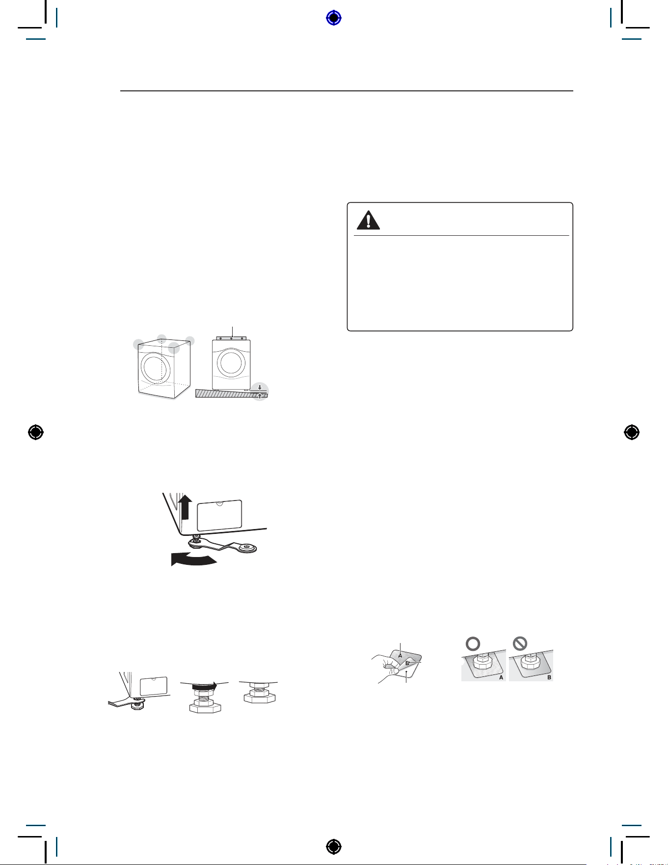
INSTALLATION INSTRUCTIONS
Leveling the washing
machine
The washer tub of your new washing machine
spins at very high speeds. To minimize vibration,
noise, and unwanted movement, the floor must be
perfectly level and solid.
1
Check the washing machine’s level.
− Check the precise level by rocking the top
edges of the washing machine or placing
a level on the washing machine. The slope
beneath the washing machine must not
exceed 1°, and all four leveling feet must
rest firmly on the floor.
1°
Level
2
Turn the lower leveling feet clockwise to level
the washing machine.
− Turning the lower leveling feet clockwise
raises the washing machine.
Raise
3
Turn the locknuts counterclockwise and
tighten them when the washing machine is
level.
Tighten all 4 lock
nuts securely using
the wrench.
4
Check the washing machine’s level again.
− Push or rock the top edges of the washing
machine gently to make sure that the
washing machine does not rock.
− If the washing machine rocks, repeat steps
1 to 3.
WARNING
• Using the washing machine without leveling,
it may result in malfunction caused by the
production of excess vibration and noise.
• Use the leveling feet only when you level
the washing machine. If you raise the
leveling feet unnecessarily, it may cause
abnormal ibration of the washing machine.
Using non-skid pads (optional)
If you install the washing machine on a slippery
surface, it may move because of excessive
vibration. Incorrect leveling may cause malfunction
through noise and vibration. In the event of this,
lay the non-skid pads under the leveling feet and
adjust the level.
1
Clean the floor to attach the non-skid pads.
− Use a dry rag to remove and clean foreign
objects or moisture. If moisture remains, the
non-skid pads may slip.
2
Adjust the level after placing the washing
machine in the installation area.
3
Place the adhesive side of the non-skid pad
on the floor.
− It is most effective to install the non-skid
pads under the front legs. If it is hard to
place the pads under the front legs, place
them under the back legs.
This side up
Remove
backing
Adhesive
side
4
Check the washing machine’s level again.
− Push or rock the top edges of the washing
machine gently to make sure that the
washing machine does not rock. If the
washing machine rocks, level the washing
machine again.

21
PREPARATION
HEATER
• Check all pockets to make sure that they are
empty.
− Items such as clips, matches, pens, coins,
and keys can damage both your washer and
your clothes.
• Close zippers, hooks, and drawstrings to
prevent these items from snagging or tangling
on other clothes.
• Pretreat heavily stained areas before washing.
− Doing so will produce clean, stain-free
results.
• Combine large and small items in a load. Load
large items first.
• The washer can be fully loaded, but the drum
should not be tightly packed with items.
− The door of the washer should close easily.
• Do not wash waterproof clothes.
− This may cause abnormal vibration or may
cause the load to bounce, which could
damage the tub.
• Check if there are any other foreign objects in
the door seal and take extra care that clothes
do not get caught there.
− Foreign objects in the door seal may stain
clothes, and water may leak if clothes get
caught in the door seal.
• Wash underwear or small, light items in a
laundry net.
− Small, light items may get caught in the door
seal, and a brassiere hook may damage
other items or the tub.
• Brush heavy soil, dust, or hair off fabrics before
washing.
− Laundry may not wash clean if there is dirt or
sand on the fabrics, or they may be damaged
due to particles rubbing against sheer fabrics.
• Wash blankets individually.
− Washing more than one blanket together
may produce unclean results due to tangling
or an unbalanced load.
• Always separate fabrics according to their
colors and wash them separately to prevent
colors from running.
− Fabrics may damage or become stained
due to fabric dyes running or due to foreign
objects transferring from one fabric to
another.
PREPARATION
Precautions for fabric care before wash cycle
Read and observe the following to prevent shrinkage or damage to clothes.
22
PREPARATION
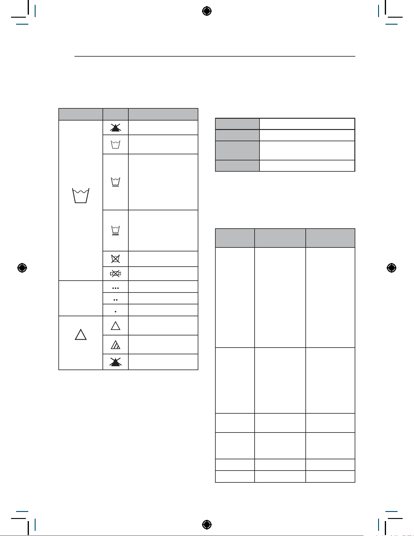
Fabric care labels
Most articles of clothing feature fabric care labels
that include instructions for proper care.
Category Label Directions
Washing
Hand Wash
Machine Wash, Normal
Cycle
Use Permanent Press/
Wrinkle Resistant
washing machine
setting (which has
a cool down or cold
spray before the
reduced spin)
Use Gentle/Delicate
washing machine
setting (slow agitation
and/ or reduced wash
time).
Do Not Wash
Do Not Wring
Water
Temperature
Hot
Warm
Cold/Cool
Bleach
symbols
Any Bleach (When
Needed)
Only Non-Chlorine
Bleach (When Needed)
Do Not Bleach
Sorting laundry
It is recommended that you sort laundry into
similar loads that are washable in the same cycle.
Refer to the following chart for sorting clothes
Colors Whites / Lights / Darks
Soil Heavy / Normal / Light
Fabric
Delicates / Easy Care / Sturdy
Cottons
Lint Lint Producers / Lint Collectors
How to wash better
It is recommended to follow the below guide for
better wash performance.
Load Type
Recommended
Capacity
How to Wash
Better
Everyday
Clothes
Less Than
10kg
Frontload
washers use
dropping
action for wash
performance.
Therefore,
it is better
to NOT fully
load the drum.
Oversudsing
also prevents
efficient wash
performance.
Blanket Less Than 7kg
Do not use 2
blankets with
big differences
in size.
It may not
extract properly.
Use similar-
sized blankets.
Bed Sheets Less Than 7kg
Any Bleach
(When Needed)
Carpet/Rug Do Not Use
Only Non-
Chlorine Bleach
(When Needed)
Footwear Do Not Use Do Not Bleach
Pillow Do Not Use
23
PREPARATION
HEATER
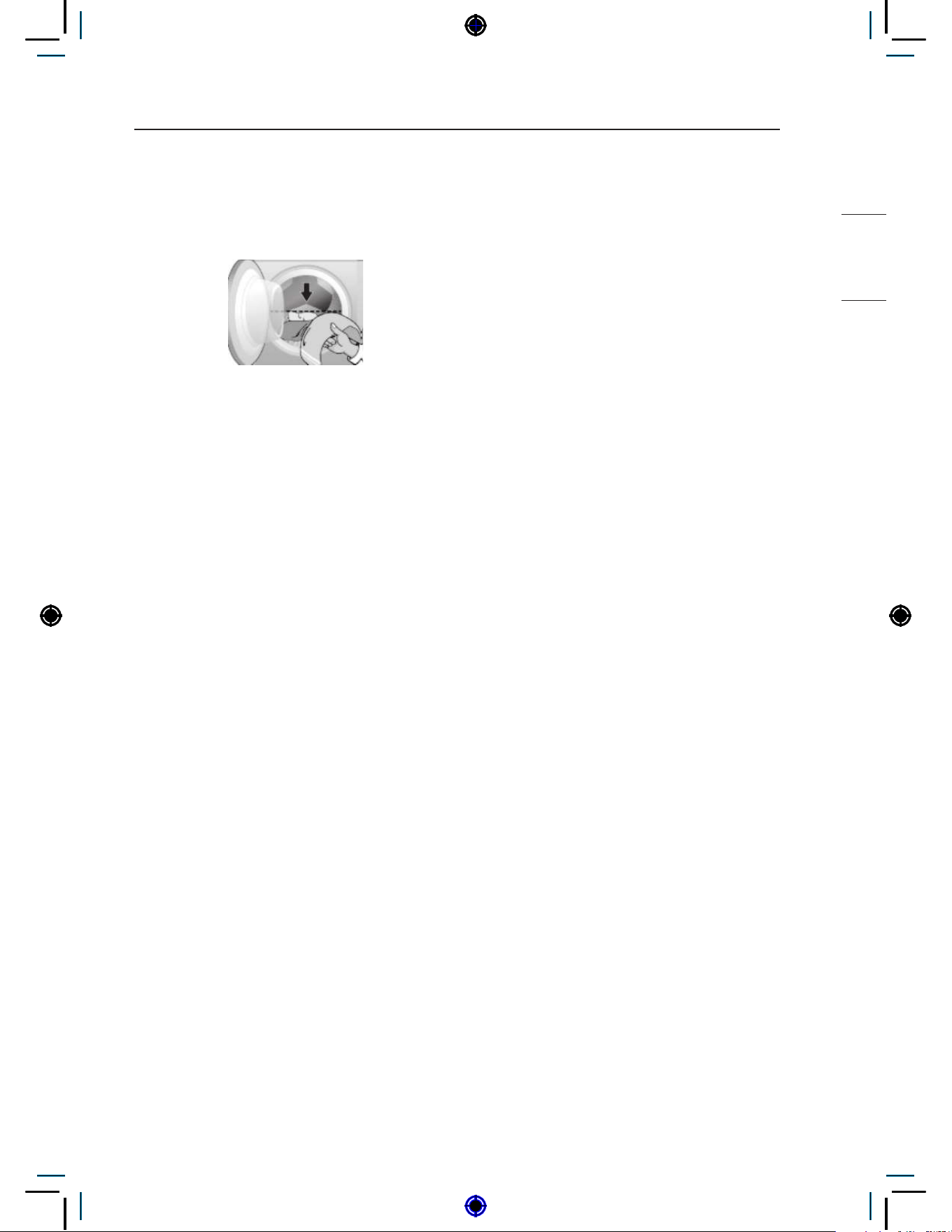
Laundry loading guide
Loading your laundry following the below guide
will help to increase the lifetime and wash
performance of the washer
• Single items or mixed items that include large
items should be less than half of the maximum
capacity(dry condition).
− Single items : Consists only of one type of
garment, such as 5kg of towel.
− Mixed items : Consists of various types of
garments.
− Large item : bed linen/sheet, bath sheet, bath
towel, and blanket.
• Mixed items (without large items) should
only be loaded up to 2/3 of the drum for
optimal performance.
NOTE
• Do not overload as this reduces cleaning
efficiency and causes gasket wear.
About the dispenser
The automatic dispenser consists of three
compartments which hold:
• Liquid chlorine bleach.
• Liquid fabric softener.
• Liquid and powdered detergent and colorsafe
bleach for main wash.
All laundry products can be added at once in their
respective dispenser compartments. They will be
dispensed at the appropriate time for the most
effective cleaning.
After adding the laundry products to the dispenser,
close the dispenser cover.
To add detergent, bleach, and fabric softener to
the automatic dispenser:
1
Open the dispenser cover.
2
Load the laundry products into the appropriate
compartments.
3
Slowly close the dispenser cover to avoid
early dispensing of the laundry products.
NOTE
• It is normal for a small amount of water to
remain in the dispenser compartments at the
end of the cycle.
24
PREPARATION
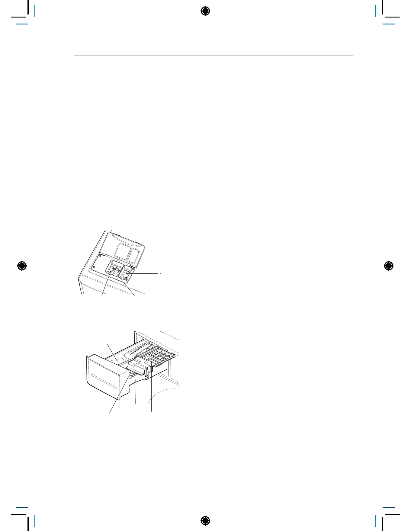
Loading the dispenser
Main Wash Detergent Compartment
This compartment holds laundry detergent for the
main wash cycle, which is added to the load at the
beginning of the cycle.
Follow the detergent manufacturer’s instructions
with respect to the amount of detergent to use, and
never use more than the recommended amount.
Using too much detergent can result in detergent
buildup in clothing and the washer. Either
powdered or liquid detergent may be used.
NOTE
• Liquid or powdered color-safe bleach may be
added to the main wash compartment with
detergent of the same type.
- Single model -
Liquid Fabric Softener
Compartment
Liquid Chlorine
Bleach Compartment
Main Wash
Detergent
Compartment
- Stack model -
Liquid Fabric Softener
Compartment
Liquid Chlorine
Bleach Compartment
Main Wash Detergent
Compartment
Liquid Bleach Compartment
This compartment holds liquid chlorine bleach,
which will be dispensed automatically at the proper
time during the wash cycle.
NOTE
• Do not add powdered or liquid color-safe
bleach to this compartment.
• Always follow the manufacturer’s
recommendations when adding bleach. Do not
exceed the maximum fill line. Using too much
bleach can damage fabrics.
• Never pour undiluted liquid chlorine bleach
directly onto the load or into the drum. Fabric
damage can occur.
Fabric Softener Compartment
This compartment holds liquid fabric softener,
which will be automatically dispensed during the
final rinse cycle.
NOTE
• Always follow the manufacturer’s
recommendations when adding fabric softener.
Do not exceed the maximum fill line. Using
too much fabric softener may result in stained
clothes.
• Dilute concentrated fabric softeners with warm
water. Do not exceed the maximum fill line.
• Never pour fabric softener directly onto the load
or into the drum.
• Do not add the fabric softener sheets to this
compartment.
• Do not add ‘fabric sheet softener’ into the
dispenser draw as it is likely to cause water
to leak out. If ‘fabric sheet softener’ has been
added, please pull out the dispenser draw and
remove.
25
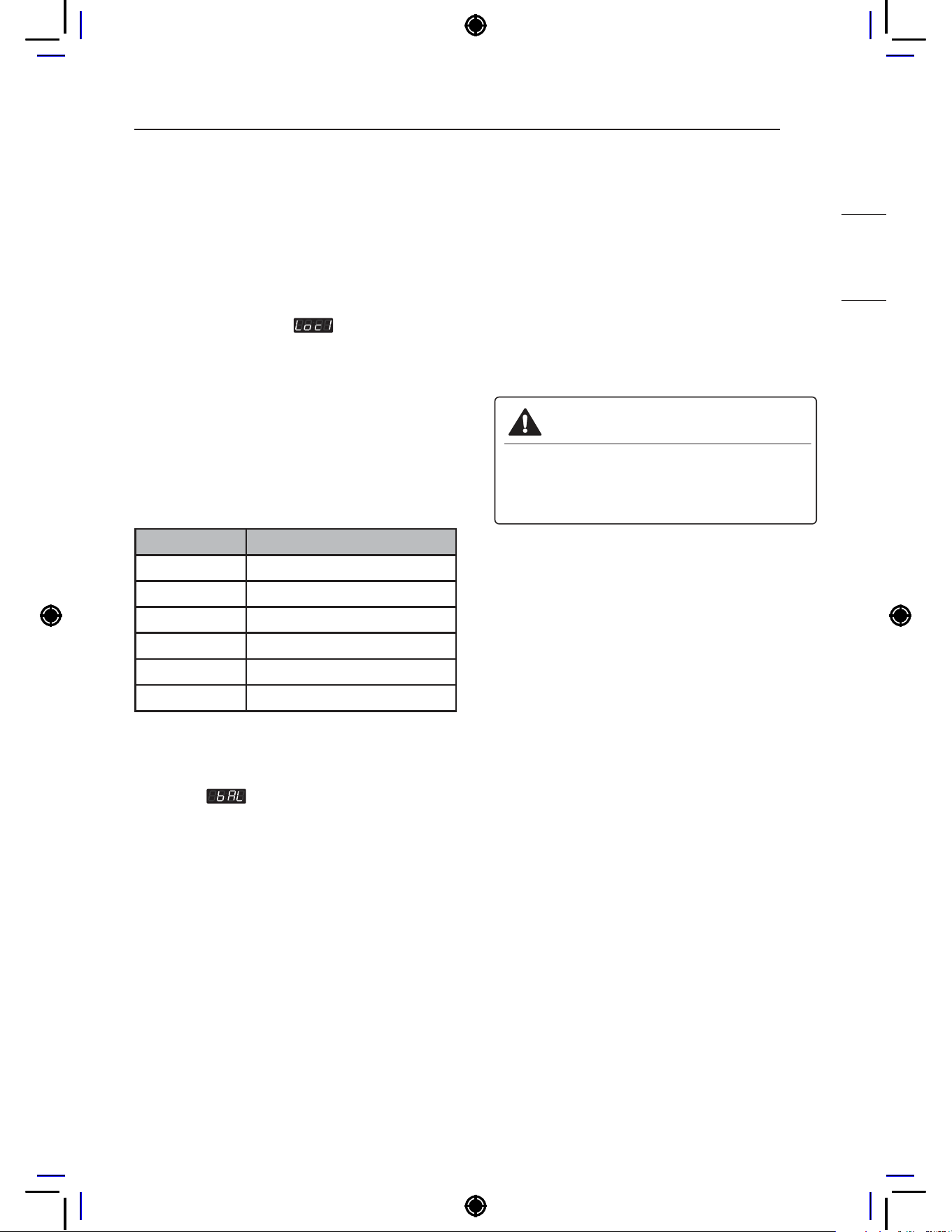
OPERATING YOUR WASHER
HEATER
1
Ready mode
− All types of machines show ‘PUSH’
NOTE
• Price setting varies by country
• Set your country from
mode
• After EEPT, reset your country (Default country
is EUK)
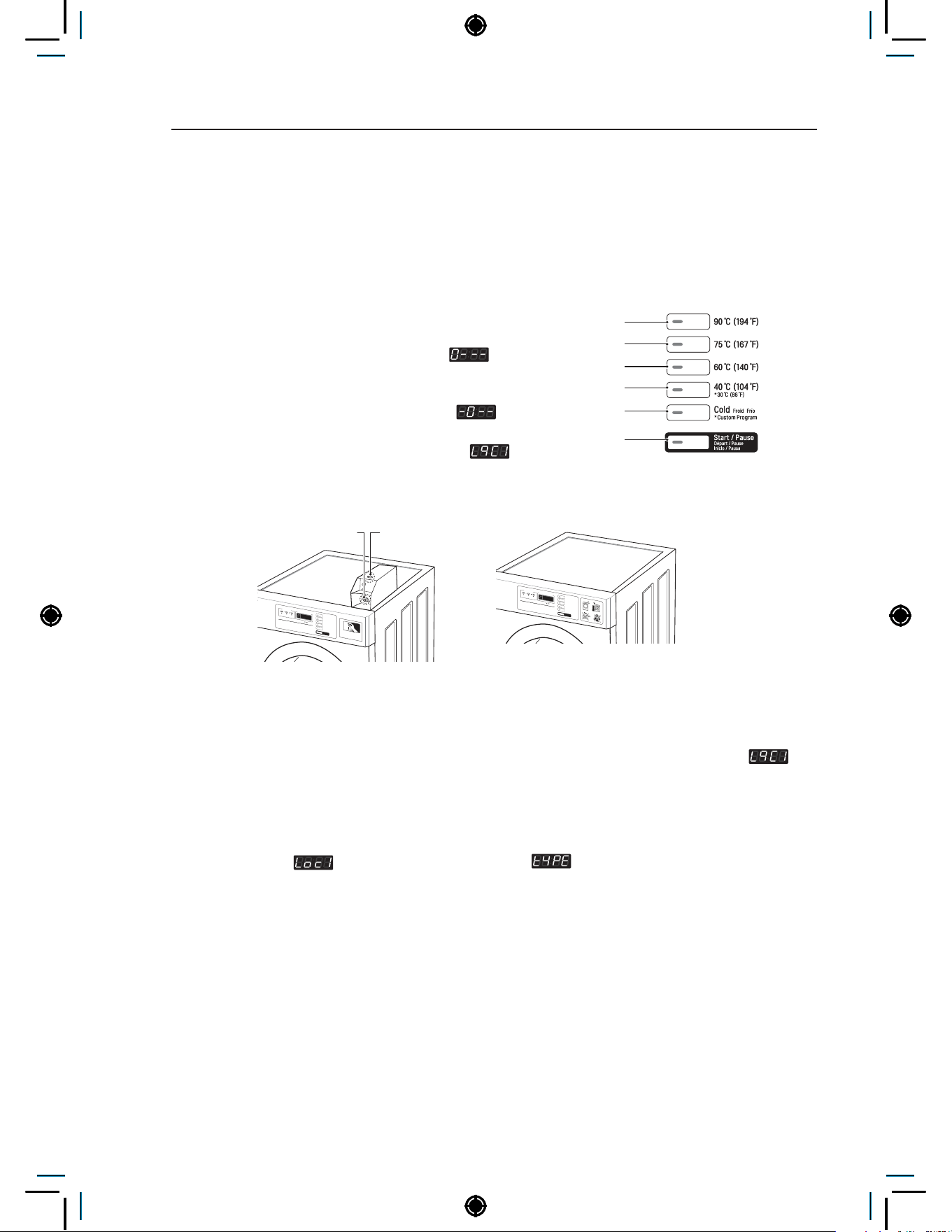
2
Select the cycle
Press the desired button and the display will show
you the price of the cycle.(You cannot change the
cycle while the machine is running.)
• Select cycles designed for different types
of fabric and soil levels.
CYCLE Wash/Rinse Temp.
90°C (194°F) Extra Hot/Cold
75°C (167°F) Extra Hot/Cold
60°C (140°F) Hot/Cold
40°C (104°F) Warm/Cold
30°C (86°F) Warm/Cold
Cold Cold/Cold
NOTE
• When the card balance is insufficient, machine
displays
and the card balance.
3
Insert Coin/Card (Not for OPL type)
Insert a sufficient amount of change that is more
than the programmed vend price for the selected
cycle.Insert a card that has a sufficient balance.
The card balance should be more than the
programmed vend price for the selected cycle.
4
Change cycle
You can not change the cycle while the machine
is running.
5
Cycle finish
The machine stops and the display shows ‘End’
with beep sound.
* Do not work any button when a cycle is in
progress.
WARNING
• To reduce the risk of fire, electric shock, or
injury to persons, read the IMPORTANT
SAFETY INSTRUCTIONS before
operating this appliance.
OPERATING YOUR WASHER
26
PROGRAMMING MODE
PROGRAMMING MODE
: You can check machine information or change setting on Program setup, collect information data,
Diagnostic test.
There are two methods that you can enter programming mode.
How to enter Programming mode:
• Coin type – Turn on/off the toggle switch.
• All types –
1
Press the 1st & 3rd button at the same time.
2
Press the 2nd & 3rd buttons to toggle numbers. Then,
press the 4th button to move to the next digit.
3
Press the Start button to finish password input.
* Default Password : 3000
<Control Panel Button>
1st
2nd
3rd
4th
5th
Start
Coin Vault
Openings close
Coin Box Key
- Coin type - - OPL type -
NOTE
• If you turn on the power without connecting meter case for the first time, the machine display
.
• When the machine is shipped from the factory, it is set in the coin type. You can change Card/Coin
type by button. (For more information refer to SETUP mode.)
• The machine will display PUSH for OPL type
• Price setting varies by country
• Set your country from
mode (Refer How to enter the )
• After EEPT, reset your country (Default country is EUK)
27
PROGRAMMING MODE
HEATER
Structure of Programming mode – Coin type
Algorithm flow chart shows how to control the programming mode.
Before program set, check the structure of the programming mode.
1
Turn on/off toggle switch or Insert service card, for entering set up mode (or follow OPL type
instructions).
2
Press 90°C (194°F) button to move to the upper level.
3
Press 75°C (167°F)(+) or 60°C (140°F)(-) button if you want to be at the same level.
4
Press Start button to enter the details of Set up or Diagnostic Tests.
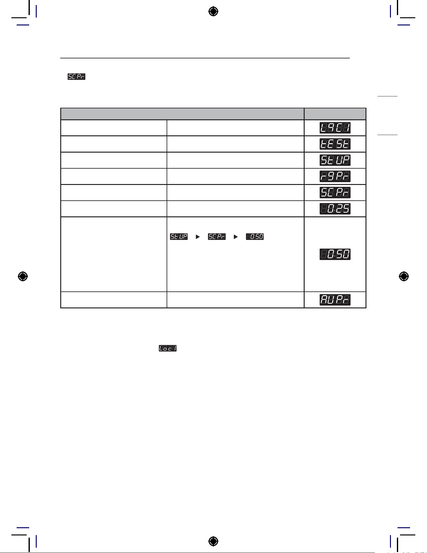
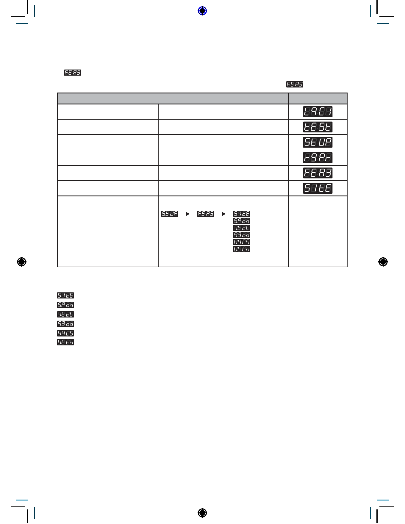
is to set price value, time value, vend type, etc.
consists of line test, reset, free cycle, and kill cycle.
is to collect the usage data.
NOTE
• Do not use
, . (It is used only in inspecting the machine.)
• Price setting varies by country
• Set your country from
mode (Refer How to enter the )
•
This function is for Card type only.
• After EEPT, reset your country (Default country is EUK)
28
PROGRAMMING MODE
Structure of Programming mode – OPL type
Algorithm flow chart shows how to control the programming mode.
Before program set, check the structure of the programming mode.
1
Turn on/off toggle switch or Insert service card, for entering set up mode (or follow OPL type
instructions).
2
Press 90°C (194°F) button to move to the upper level.
3
Press 75°C (167°F)(+) or 60°C (140°F)(-) button if you want to be at the same level.
4
Press Start button to enter the details of Set up or Diagnostic Tests.
is to set price value, time value, vend type, etc.
consists of line test, reset, free cycle, and kill cycle.
is to collect the usage data.
NOTE
• Do not use
, . (It is used only in inspecting the machine.)
29
PROGRAMING MODE – SETUP MODE
HEATER
PROGRAMING MODE – SETUP MODE
Setup Mode :
(display)
You can change washer vend price, cycle time, and cycle parameters, etc.
How to enter Programming mode:
• Coin type – Turn on/off the toggle switch.
• All types –
1
Press the 1st & 3rd button at the same time.
2
Press the 2nd & 3rd buttons to toggle numbers. Then,
press the 4th button to move to the next digit.
3
Press the Start button to finish password input.
* Default Password : 3000
<Control Panel Button>
1st
2nd
3rd
4th
5th
Start
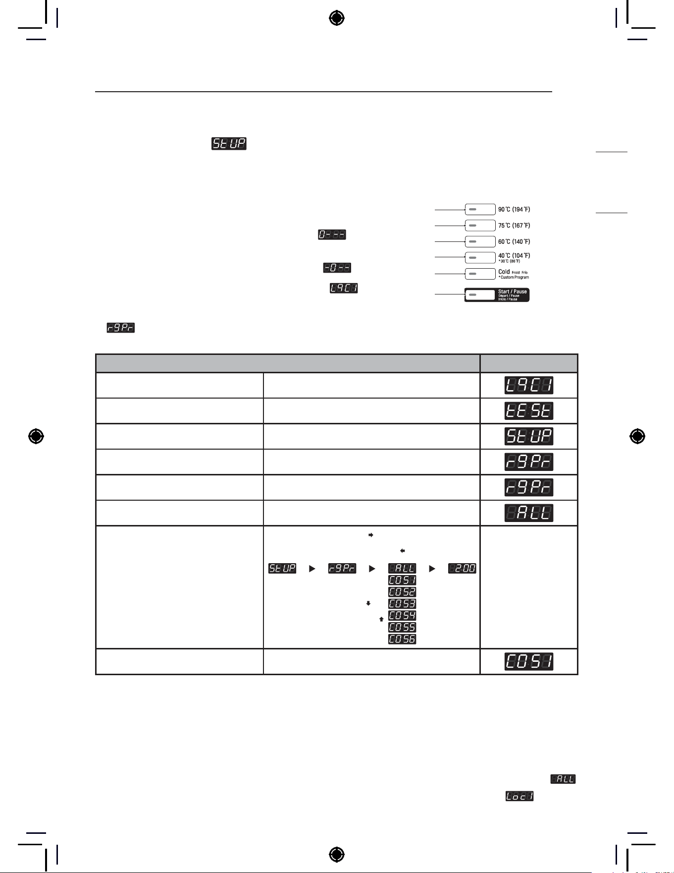
1. Regular Price Setup
How to set regular prices for all/each course.
Regular Price Setup Display
Enter SVC mode
Press 1st button
Press 2nd button
Press start button
Press 2nd button or 3rd button Until display shows
Press start button
Select the setting you want
Button functions:
Start button = Select
1st button = Go back a step
2nd button = Move up or
increase value
3rd button = Move down or
decrease value
Start button to select :
1st button to go back a step :
2nd button move up :
3rd button move to down :
Press Start to set the price The next course setting will be displayed.
NOTE
• Range : 0.00~10.00
• Increments : 0.1
• ALL is to select the default prices for all the
courses at once.
• Select individual price for COS1~6.
• COS1 : 90°C (194°F)
• COS2 : 75°C (167°F)
• COS3 : 60°C (140°F)
• COS4 : 40°C (104°F)
• COS5 : Cold
• COS6 : 30°C (86°F)
* Individual course prices are prioritized above
.
− Set your currency type using
30
PROGRAMING MODE – SETUP MODE
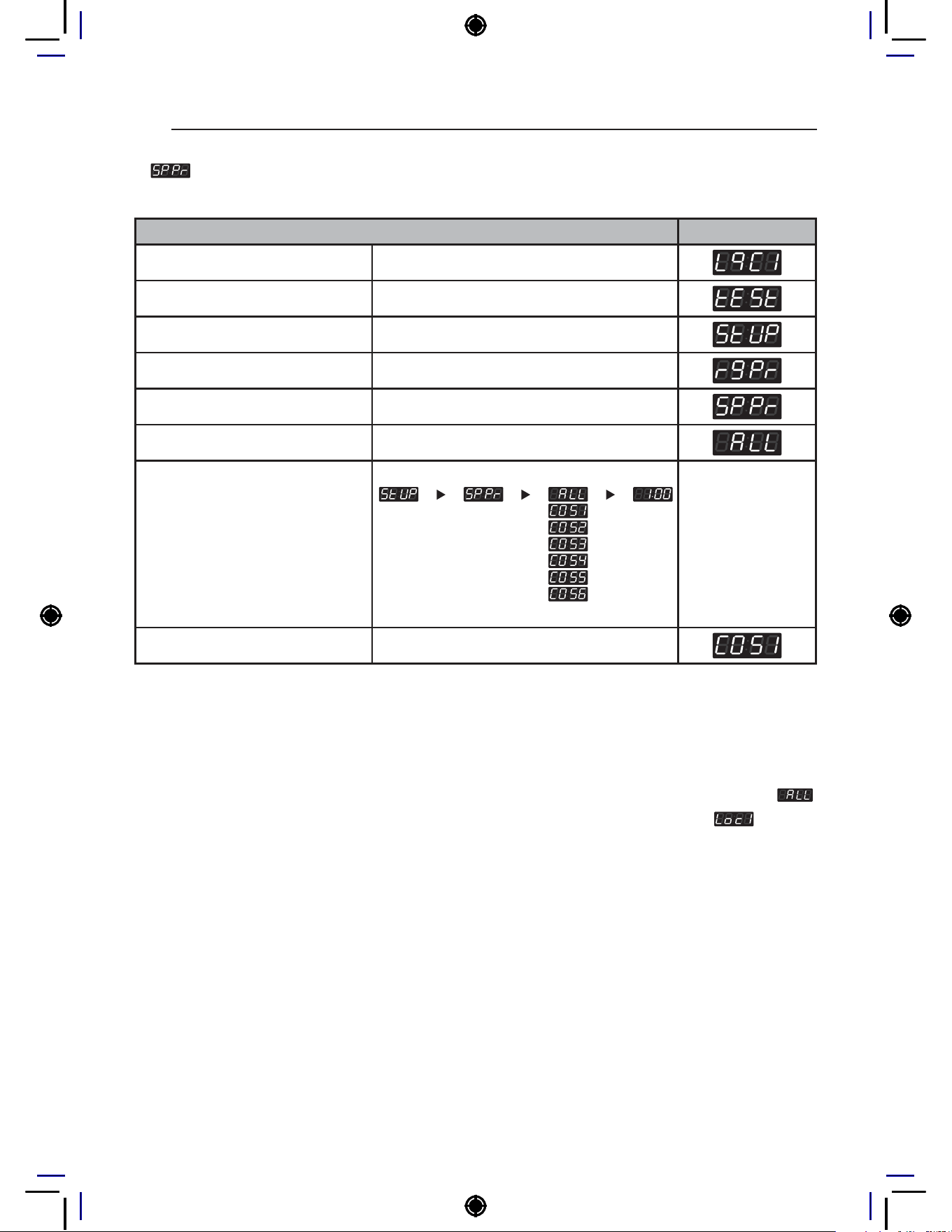
2. Special Price Setup
How to set special prices for all/each course.
Special Price Setup Display
Enter SVC mode
Press 1st button
Press 2nd button
Press start button
Press 2nd button or 3rd button Until display shows
Press start button
Select the setting you want
Button functions:
Start button = Select
1st button = Go back a step
2nd button = Move up or
increase value
3rd button = Move down or
decrease value
Press Start to set the price The next course setting will be displayed.
NOTE
• Range : 0.00~10.00
• Increments : 0.1
• ALL is to select the default prices for all the
courses at once.
• Select individual price for COS1~6.
• COS1 : 90°C (194°F)
• COS2 : 75°C (167°F)
• COS3 : 60°C (140°F)
• COS4 : 40°C (104°F)
• COS5 : Cold
• COS6 : 30°C (86°F)
* Individual course prices are prioritized above
.
− Set your currency type using
31
PROGRAMING MODE – SETUP MODE
HEATER
3. Add Super Wash Price Setup
How to set Add Super Wash Price.
* Add Super Wash is used to add extra wash, rinse, or both (only in Pay type).
Add Super Wash Price Setup Display
Enter SVC mode
Press 1st button
Press 2nd button
Press start button
Press 2nd button or 3rd button Until display shows
Press start button
Select the setting you want
Button functions:
Start button = Select
1st button = Go back a step
2nd button = Move up or
increase value
3rd button = Move down or
decrease value
Press Start to set the price The next menu setting will be displayed.
NOTE
• Range : 0.00~10.00
• Increments : 0.1
− Set your currency type using

32
PROGRAMING MODE – SETUP MODE
4. Auto Dosing Price Setup
How to set Auto Dosing Price.
* Auto dosing is used to inject detergent/chemicals using external pumps (only in Pay type).
Auto Dosing Price Setup Display
Enter SVC mode
Press 1st button
Press 2nd button
Press start button
Press 2nd button or 3rd button Until display shows
Press start button
Select the setting you want
Button functions:
Start button = Select
1st button = Go back a step
2nd button = Move up or
increase value
3rd button = Move down or
decrease value
Press Start to set the price The next menu setting will be displayed.
NOTE
• Range : 0.00~10.00
• Increments : 0.1
− Set your currency type using
33
PROGRAMING MODE – SETUP MODE
HEATER
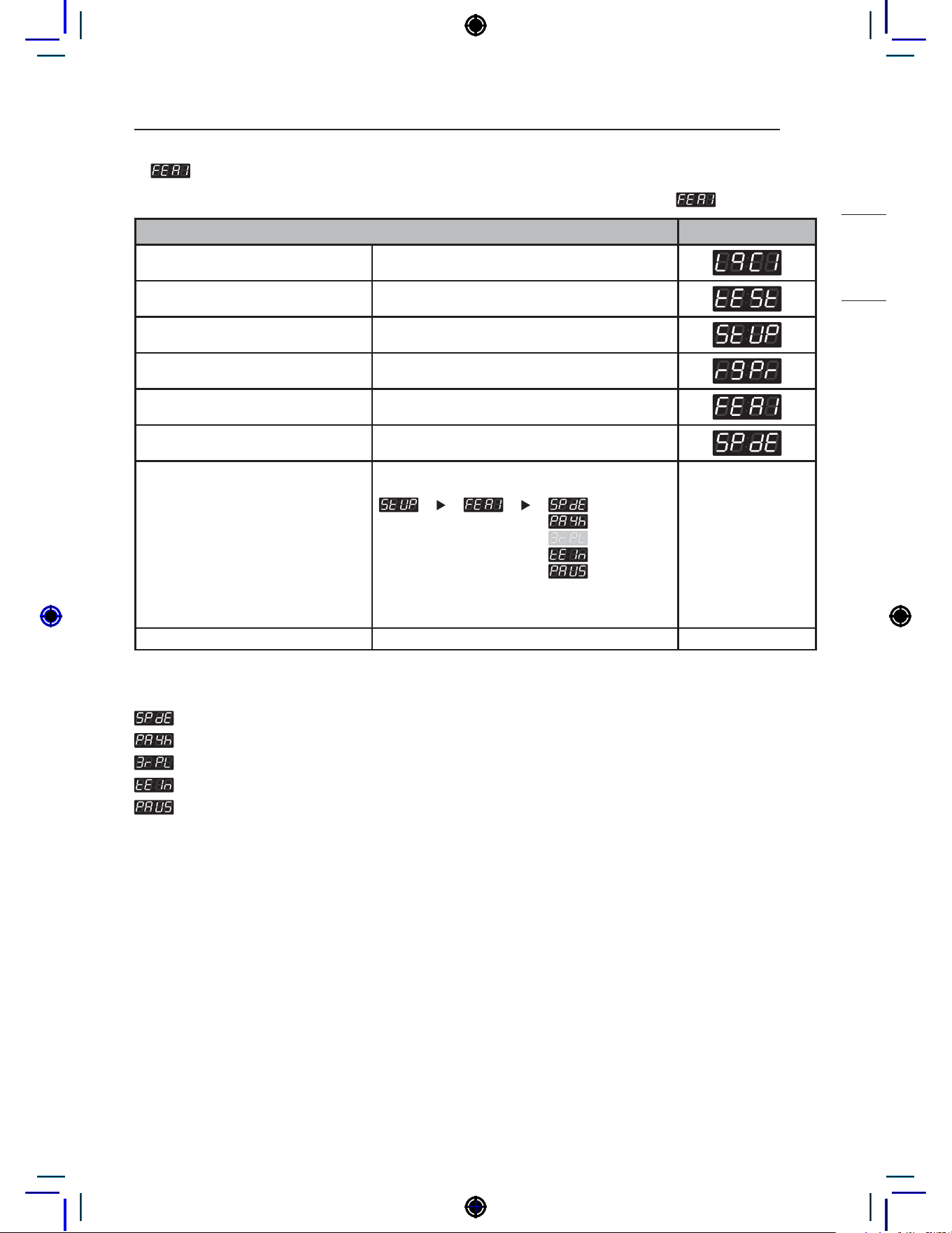
5. Features of the Machine (1st Set)
How to set up Features of the Machine. There are multiple setup features under .
Features of the Machine (1st Set) Display
Enter SVC mode
Press 1st button
Press 2nd button
Press start button
Press 2nd button or 3rd button Until display shows
Press start button
Select the setting you want
Button functions:
Start button = Select
1st button = Go back a step
2nd button = Move up or
increase value
3rd button = Move down or
decrease value
Press Start to set sub-function
NOTE
: Special price day enable or disable
: Easy entry payment cycle kill enable or disable
: Maximum rpm limit enable or disable
: Twin spray enable or disable
: Pause function enable or disable
34
PROGRAMING MODE – SETUP MODE
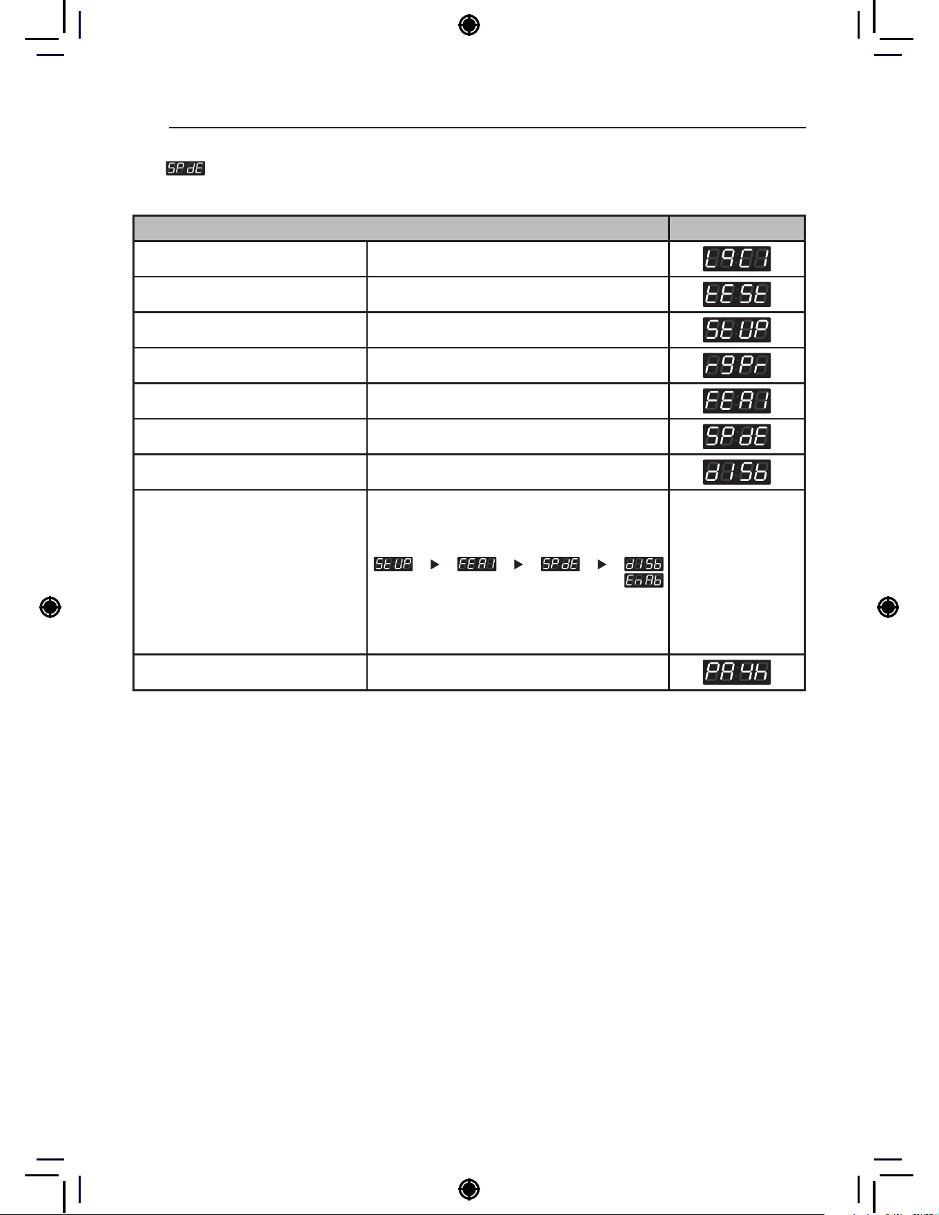
5-1. Special Price Day Setup
Special Price Day Setup can be used to enable/disable the use of special prices.
Special Price Day Setup Display
Enter SVC mode
Press 1st button
Press 2nd button
Press start button
Press 2nd button or 3rd button Until display shows
Press start button
Press start button
Select the setting you want
Button functions:
Start button = Select
1st button = Go back a step
2nd button = Move up or
increase value
3rd button = Move down or
decrease value
Press Start to enable or disable The next menu setting will be displayed.

35
PROGRAMING MODE – SETUP MODE
HEATER
5-2. Easy Entry Payment Cycle Kill Setup
Easy entry cycle kill can be enabled or disabled in the payment cycle
Easy Entry Payment Cycle Kill Setup Display
Enter SVC mode
Press 1st button
Press 2nd button
Press start button
Press 2nd button or 3rd button Until display shows
Press start button
Press 2nd button or 3rd button Until display shows
Press start button
Select the setting you want
Button functions:
Start button = Select
1st button = Go back a step
2nd button = Move up or
increase value
3rd button = Move down or
decrease value
Press Start to enable or disable The next menu setting will be displayed.
NOTE
Shortcut key not available
Shortcut key available
• Shortcut key : Press and hold the start button for at least 3seconds
36
PROGRAMING MODE – SETUP MODE
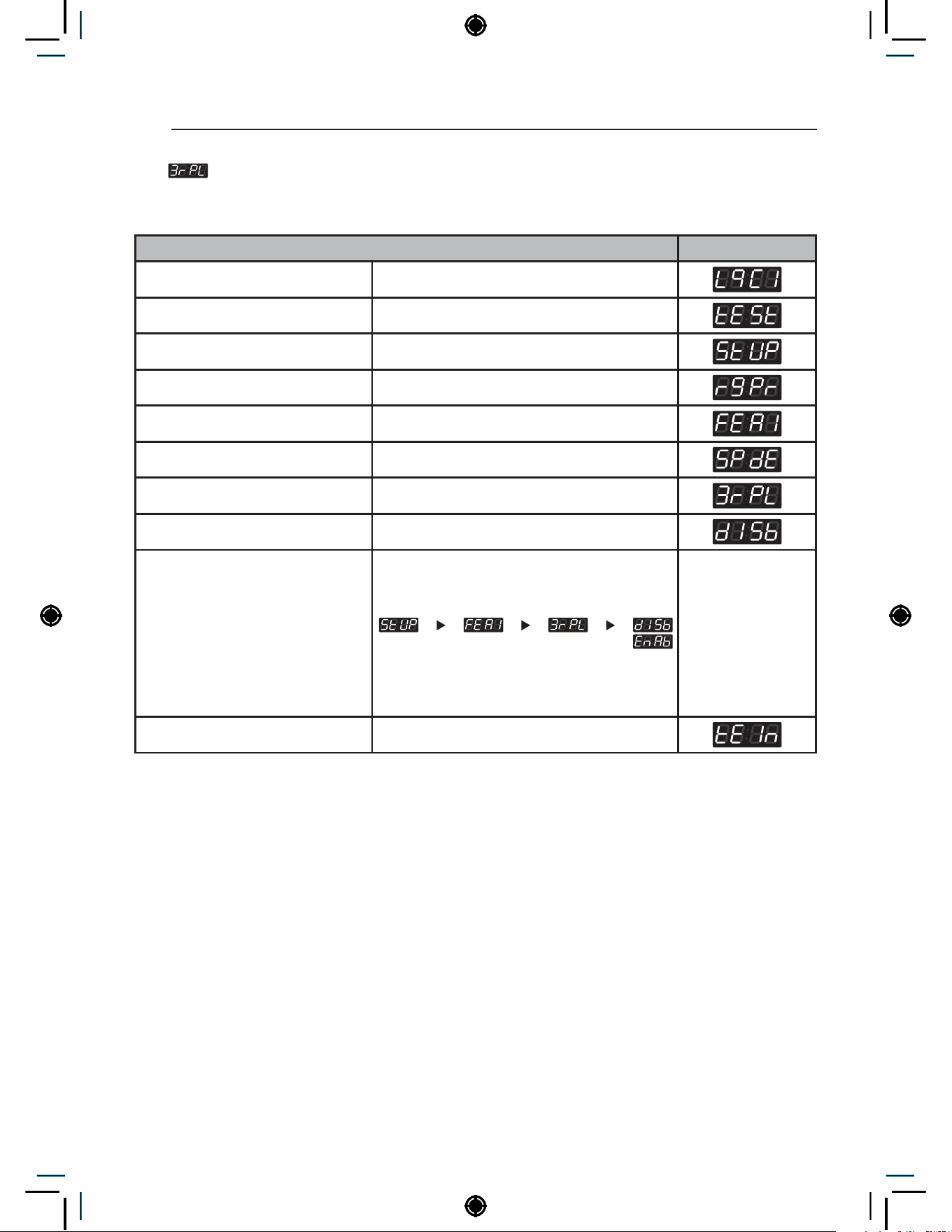
5-3. Max RPM Limit Setup
Max RPM Limit Setup can be used to enable/disable the ability to limit the max RPM during spin
process.
Max RPM Limitation Setup Display
Enter SVC mode
Press 1st button
Press 2nd button
Press start button
Press 2nd button or 3rd button Until display shows
Press start button
Press 2nd button or 3rd button Until display shows
Press start button
Select the setting you want
Button functions:
Start button = Select
1st button = Go back a step
2nd button = Move up or
increase value
3rd button = Move down or
decrease value
Press Start to enable or disable The next menu setting will be displayed.
NOTE
If enabled, the max RPM will adjust according to the laundry load.
Max RPM will be reduced for highly unbalanced loads.

37
PROGRAMING MODE – SETUP MODE
HEATER
5-4. Twin Spray Setup
Twin Spray Setup can be used to enable/disable water circulation during tumble.
Twin Spray Setup Display
Enter SVC mode
Press 1st button
Press 2nd button
Press start button
Press 2nd button or 3rd button Until display shows
Press start button
Press 2nd button or 3rd button Until display shows
Press start button
Select the setting you want
Button functions:
Start button = Select
1st button = Go back a step
2nd button = Move up or
increase value
3rd button = Move down or
decrease value
Press Start to enable or disable The next menu setting will be displayed.
NOTE
For better wash performance, twin spray pumps up water from the bottom of the tub to spray soapy water
on laundry while tumbling.
38
PROGRAMING MODE – SETUP MODE
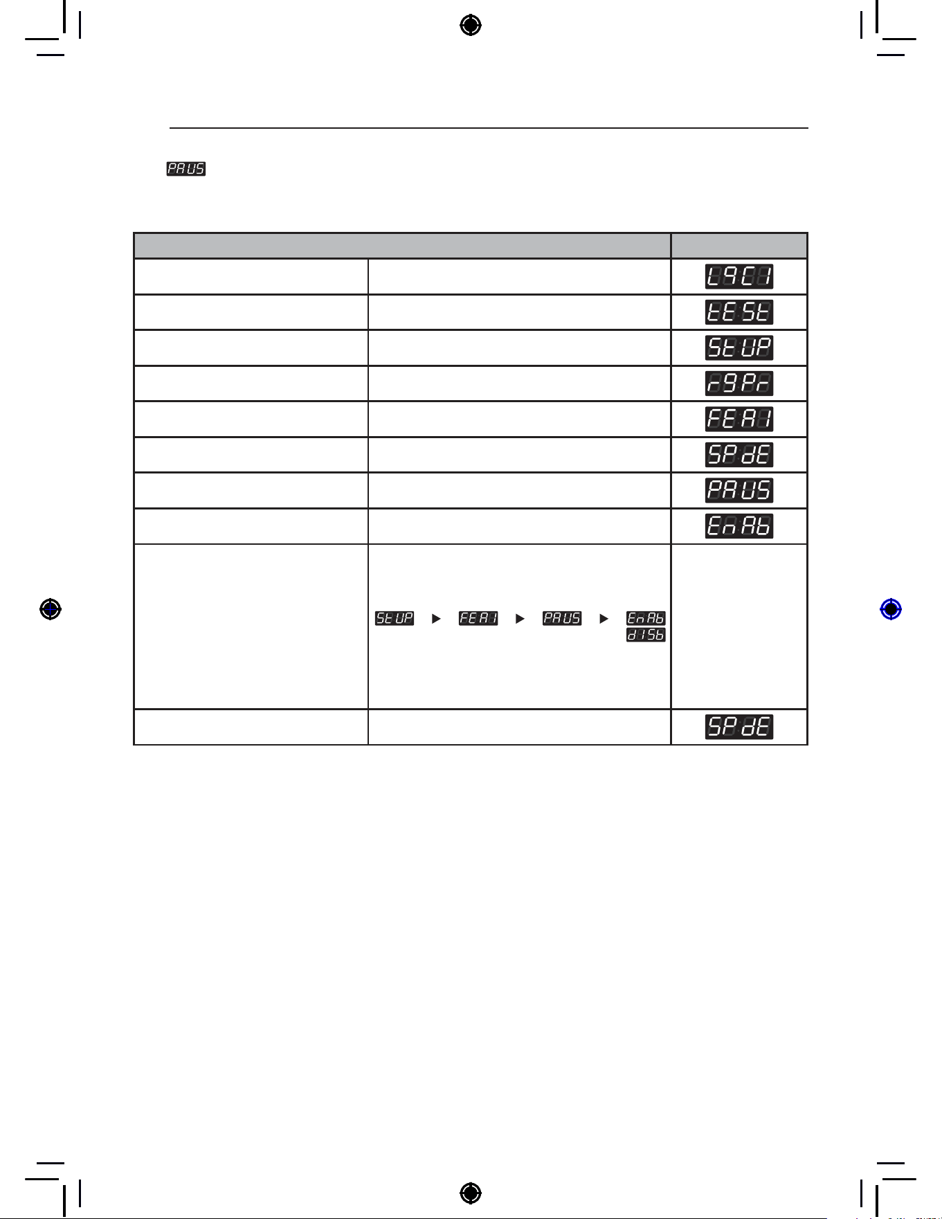
5-5. Pause Function Setup
Pause Function Setup can be used to enable/disable the ability to pause the cycle when pressing
the start/pause button.
Pause Function Setup Display
Enter SVC mode
Press 1st button
Press 2nd button
Press start button
Press 2nd button or 3rd button Until display shows
Press start button
Press 2nd button or 3rd button Until display shows
Press start button
Select the setting you want
Button functions:
Start button = Select
1st button = Go back a step
2nd button = Move up or
increase value
3rd button = Move down or
decrease value
Press Start to enable or disable The next menu setting will be displayed.
39
PROGRAMING MODE – SETUP MODE
HEATER
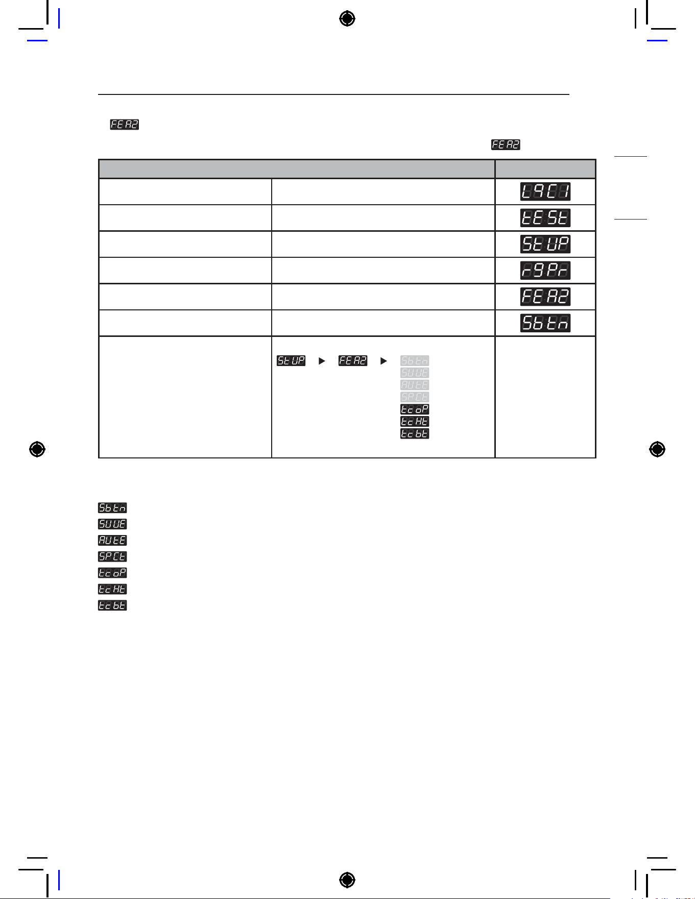
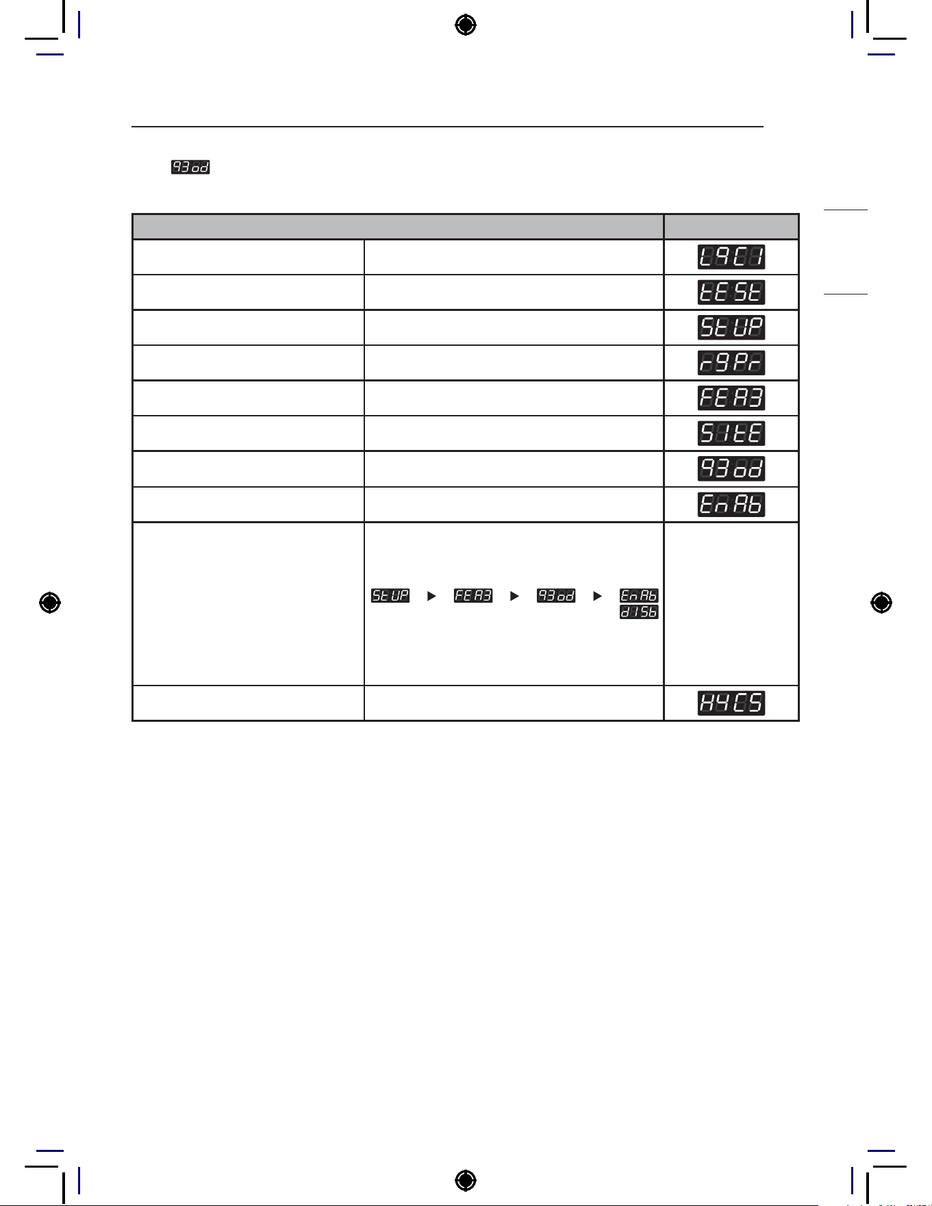
6. Features of the Machine (2nd Set)
How to set up features of the machine. There are multiple setup features under .
Features of the Machine (2nd Set) Display
Enter SVC mode
Press 1st button
Press 2nd button
Press start button
Press 2nd button or 3rd button Until display shows
Press start button
Select the setting you want
Button functions:
Start button = Select
1st button = Go back a step
2nd button = Move up or
increase value
3rd button = Move down or
decrease value
NOTE
: 5th button fuction select (Add super wash or Auto dosing charging)
: Add super wash enable or disable
: Auto dosing function enable or disable
: Add super wash type
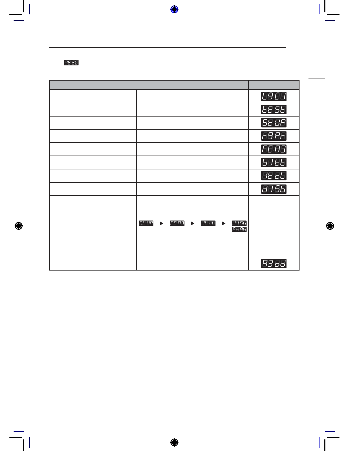
: Tub clean load detection enable or disable
: Tub clean heater usage enable or disable
: Tub clean easy entry function enable or disable

40
PROGRAMING MODE – SETUP MODE
6-1. 5th Button Type Setup
5th Button Type Setup can be used to set the function of the 5th button.
5th Button Type Setup Display
Enter SVC mode
Press 1st button
Press 2nd button
Press start button
Press 2nd button or 3rd button Until display shows
Press start button
Press 2nd button or 3rd button Until display shows
Select the setting you want
Button functions:
Start button = Select
1st button = Go back a step
2nd button = Move up or
increase value
3rd button = Move down or
decrease value
Press Start to set sub-fuction Display returns to standby mode.
NOTE
Setting to
will make the 5th button function as Add Super Wash.
Setting to
will make the 5th button function as payment for auto dosing.
41
PROGRAMING MODE – SETUP MODE
HEATER
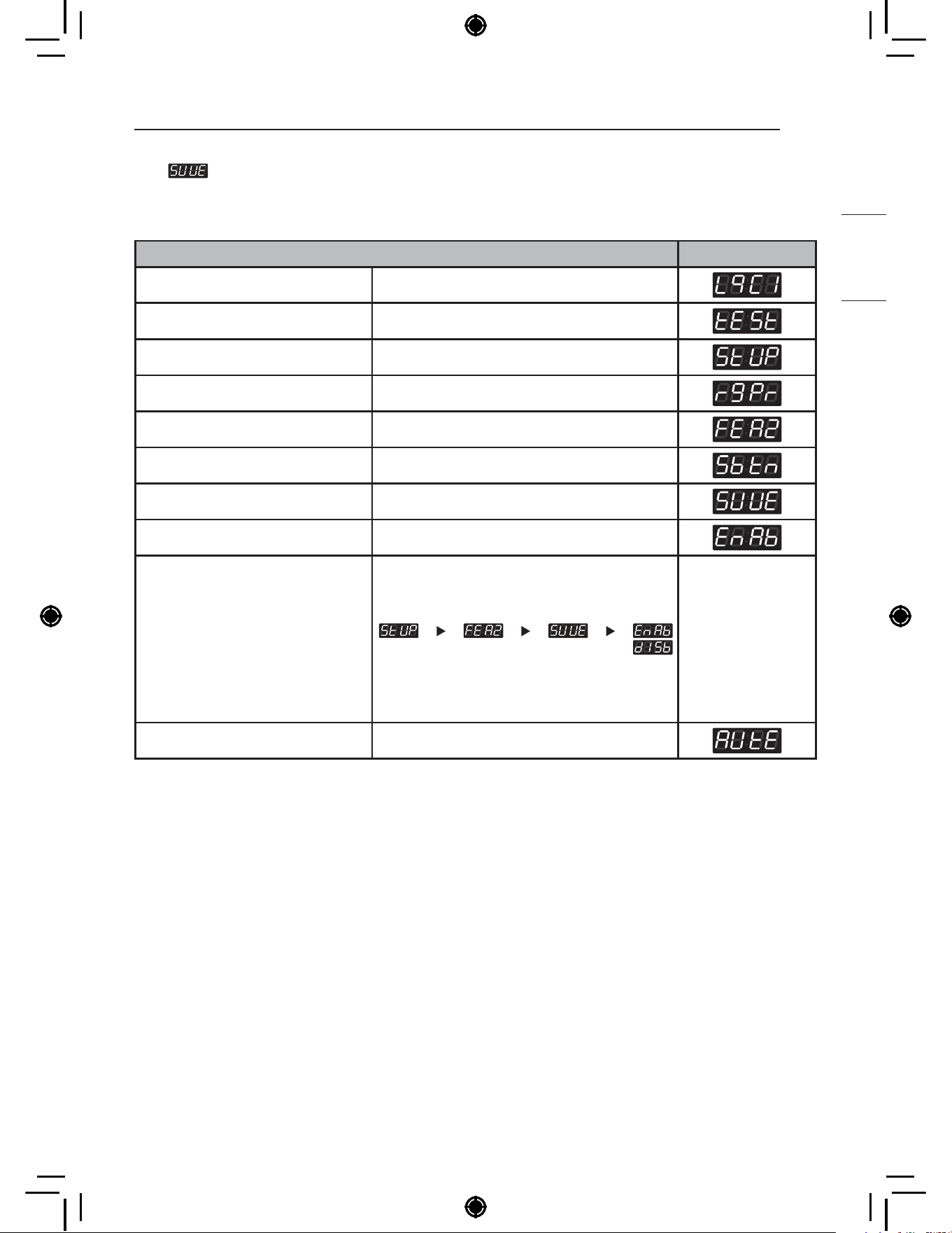
6-2. Add Super Wash Setup
Add Super Wash Setup can be used to enable/disable the super wash function.
* Add Super Wash is used to add extra wash, rinse, or both (only used in Pay type).
Add Super Wash Setup Display
Enter SVC mode
Press 1st button
Press 2nd button
Press start button
Press 2nd button or 3rd button Until display shows
Press start button
Press 2nd button or 3rd button Until display shows
Press start button
Select the setting you want
Button functions:
Start button = Select
1st button = Go back a step
2nd button = Move up or
increase value
3rd button = Move down or
decrease value
Press Start to enable or disable The next menu setting will be displayed.

42
PROGRAMING MODE – SETUP MODE
6-3. Auto Dosing Setup
Auto Dosing Setup can be used to enable/disable the Auto dosing function.
Auto Dosing Setup Display
Enter SVC mode
Press 1st button
Press 2nd button
Press start button
Press 2nd button or 3rd button Until display shows
Press start button
Press 2nd button or 3rd button Until display shows
Press start button
Select the setting you want
Button functions:
Start button = Select
1st button = Go back a step
2nd button = Move up or
increase value
3rd button = Move down or
decrease value
Press Start to enable or disable The next menu setting will be displayed.

43
PROGRAMING MODE – SETUP MODE
HEATER
6-4. Add Super Wash Type Setup
Add Super Wash Type Setup can be used to add extra wash cycle, rinse cycle, or both.
Add Super Wash Type Setup Display
Enter SVC mode
Press 1st button
Press 2nd button
Press start button
Press 2nd button or 3rd button Until display shows
Press start button
Press 2nd button or 3rd button Until display shows
Press start button
Select the setting you want
Button functions:
Start button = Select
1st button = Go back a step
2nd button = Move up or
increase value
3rd button = Move down or
decrease value
Press Start to set sub-fuction The next menu setting will be displayed.
NOTE
: Both (Increase wash time and rinse once more)
: Increase wash time
: Rinse once more

44
PROGRAMING MODE – SETUP MODE
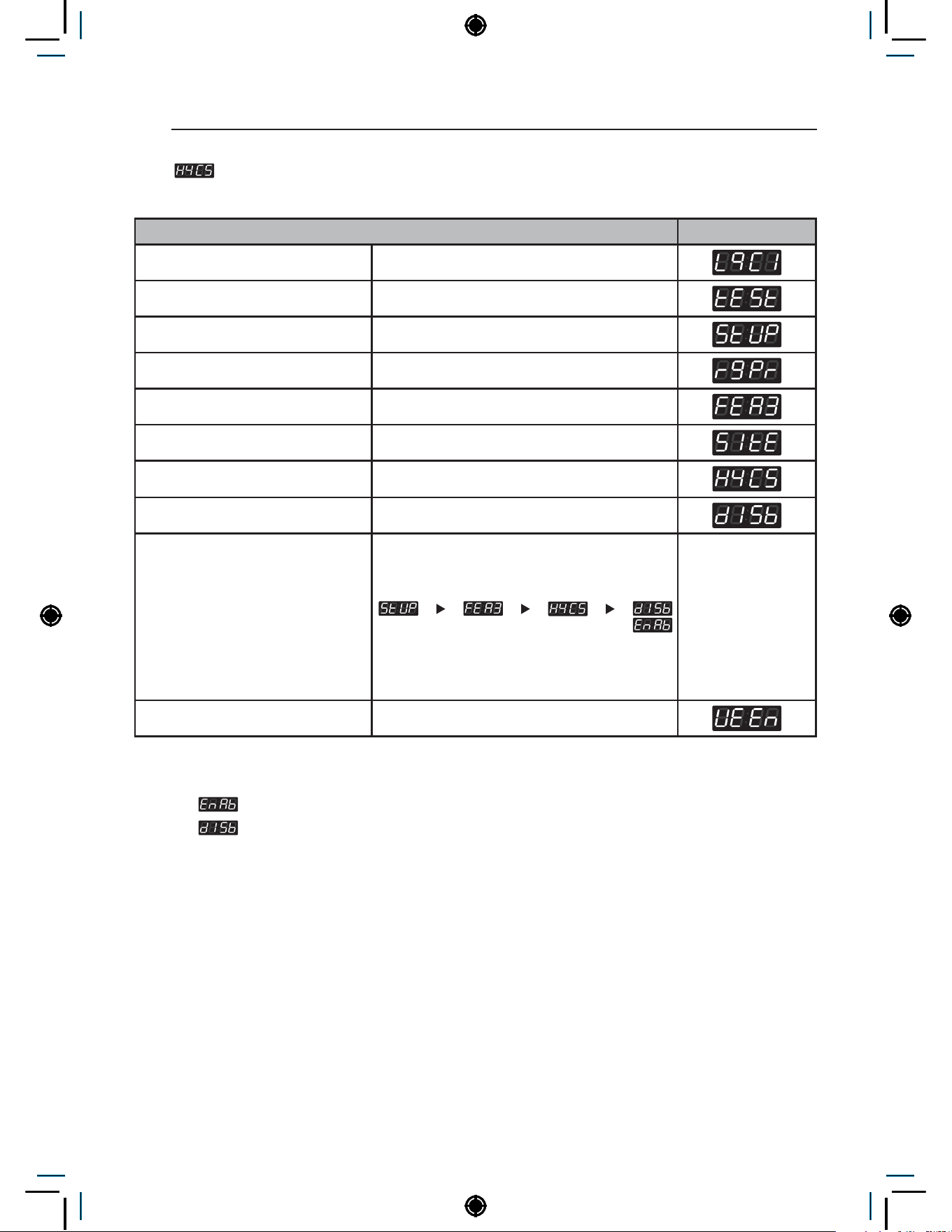
6-5. Tub Clean Load Detection Setup
Tub Clean Load Detection Setup can be used to enable/disable the ability to detect laundry load
during tub clean. If enabled, the washer will detect whether or not a load is present in the washer.
Tub Clean Load Detection Setup Display
Enter SVC mode
Press 1st button
Press 2nd button
Press start button
Press 2nd button or 3rd button Until display shows
Press start button
Press 2nd button or 3rd button Until display shows
Press start button
Select the setting you want
Button functions:
Start button = Select
1st button = Go back a step
2nd button = Move up or
increase value
3rd button = Move down or
decrease value
Press Start to enable or disable The next menu setting will be displayed.
45
PROGRAMING MODE – SETUP MODE
HEATER
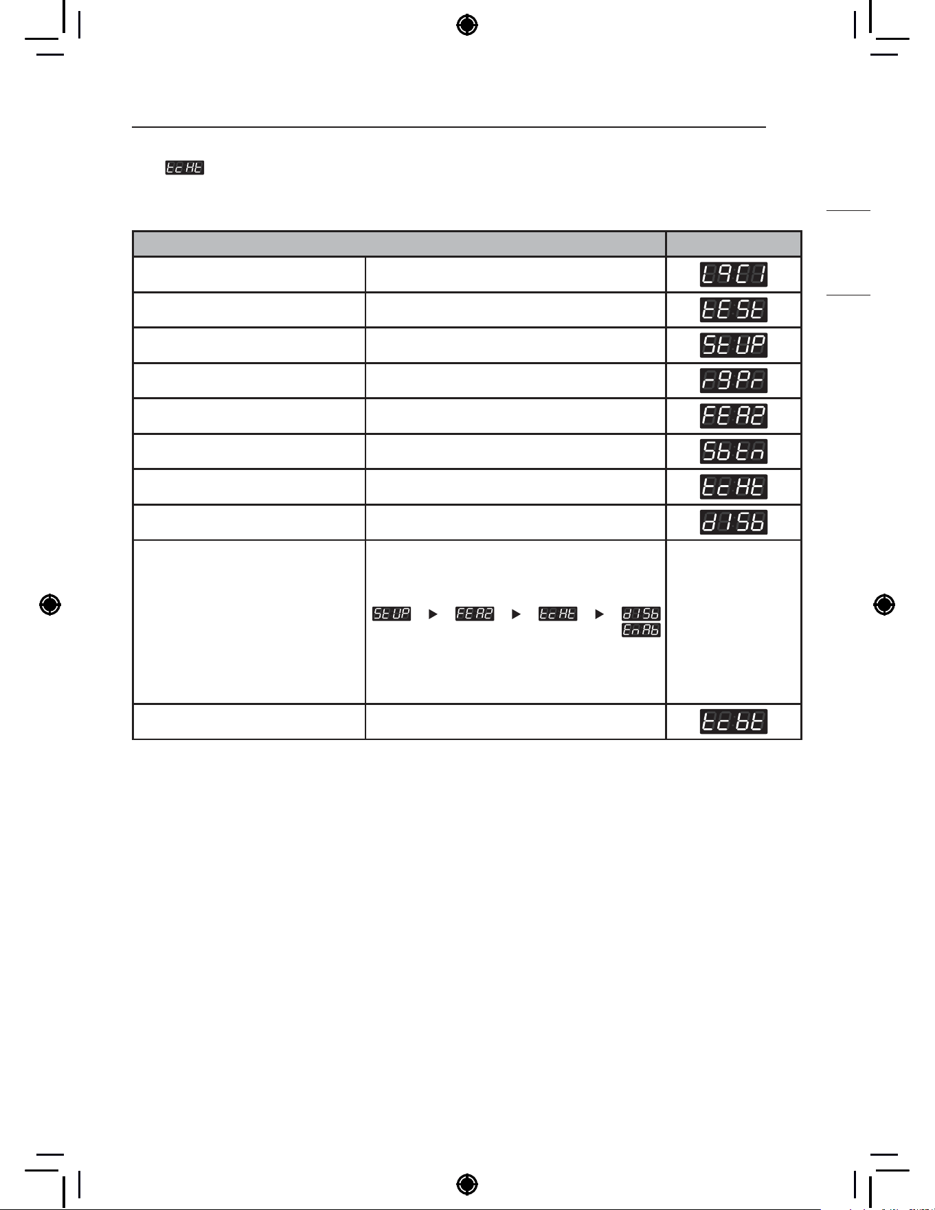
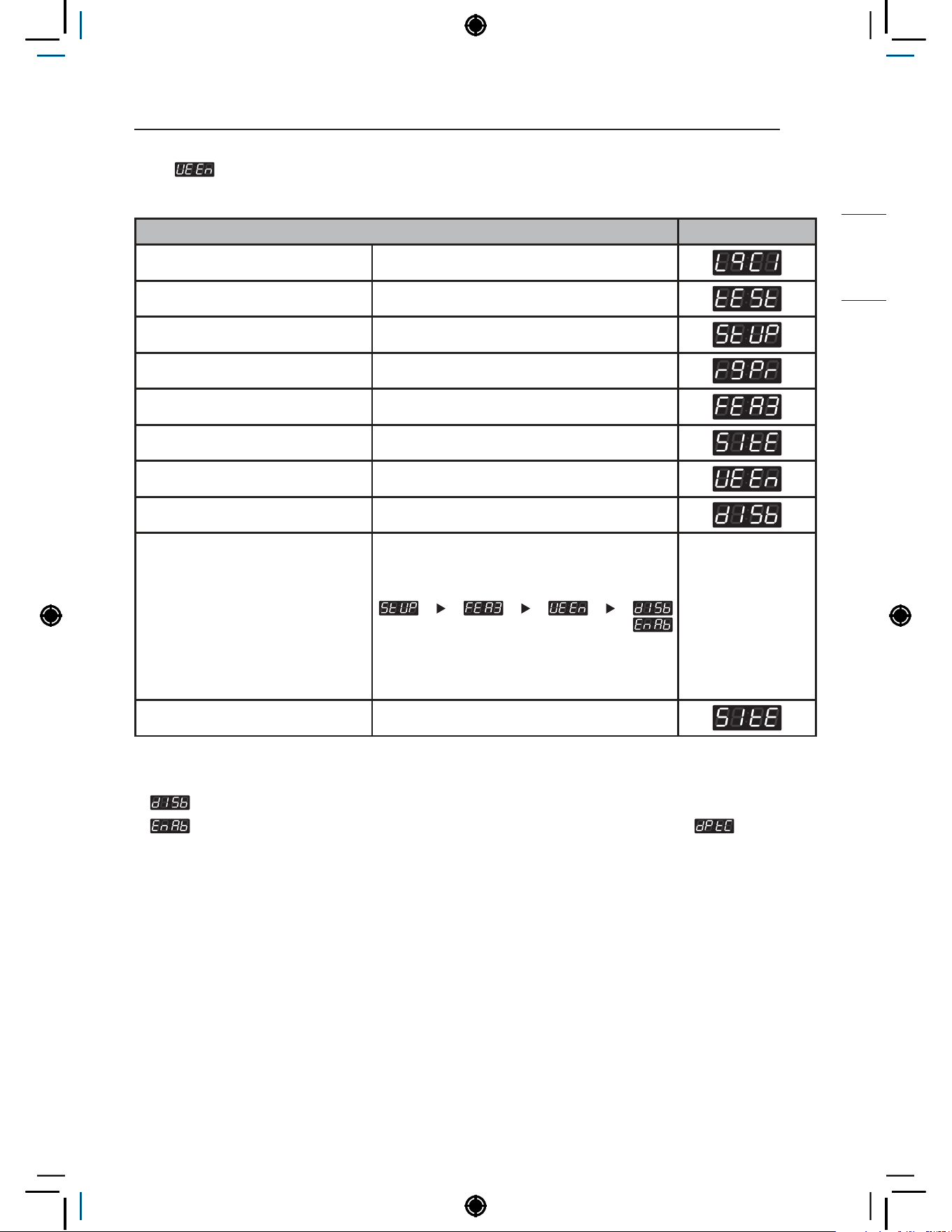
6-6. Tub Clean Heater Setup
Tub Clean Heater Setup can be used to enable/disable the ability to use the heater during tub clean.
If enabled, the heater will be used for the tub clean.
Tub Clean Heater Setup Display
Enter SVC mode
Press 1st button
Press 2nd button
Press start button
Press 2nd button or 3rd button Until display shows
Press start button
Press 2nd button or 3rd button Until display shows
Press start button
Select the setting you want
Button functions:
Start button = Select
1st button = Go back a step
2nd button = Move up or
increase value
3rd button = Move down or
decrease value
Press Start to enable or disable The next menu setting will be displayed.

46
PROGRAMING MODE – SETUP MODE
6-7. Tub Clean Button Setup
Tub Clean Button Setup can be used to enable/disable the easy entry function for the new tub clean
Tub Clean Button Setup Display
Enter SVC mode
Press 1st button
Press 2nd button
Press start button
Press 2nd button or 3rd button Until display shows
Press start button
Press 2nd button or 3rd button Until display shows
Press start button
Select the setting you want
Button functions:
Start button = Select
1st button = Go back a step
2nd button = Move up or
increase value
3rd button = Move down or
decrease value
Press Start to enable or disable The next menu setting will be displayed.
NOTE
Shortcut key not available
Shortcut key available (Press and hold 1st and 2nd button in same time)
47
PROGRAMING MODE – SETUP MODE
HEATER
7. Features of the Machine (3rd Set)
How to set up features of the machine. There are multiple setup features under .
Features of the Machine (3rd Set) Display
Enter SVC mode
Press 1st button
Press 2nd button
Press start button
Press 2nd button or 3rd button Until display shows
Press start button
Select the setting you want
Button functions:
Start button = Select
1st button = Go back a step
2nd button = Move up or
increase value
3rd button = Move down or
decrease value
NOTE
: Spin type
: Spin only easy entry function enable or disable
: Initial tub clean enable or disable
: quick mode enable or disable
: hygiene cycle enable or disable
: UE Error enable or disable

48
PROGRAMING MODE – SETUP MODE
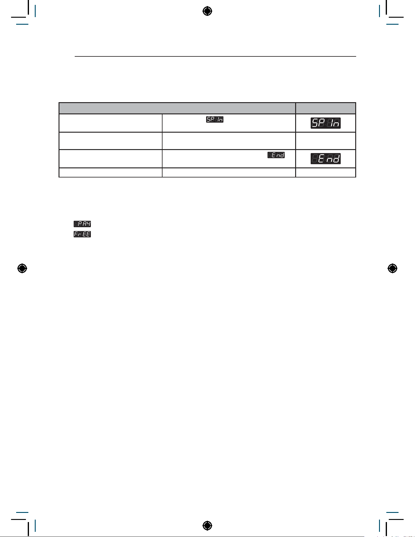
7-1. Spin Type Setup
Spin Type Setup can be used to select spin type between multi-housing type and coin laundry type.
Spin Type Setup Display
Enter SVC mode
Press 1st button
Press 2nd button
Press start button
Press 2nd button or 3rd button Until display shows
Press start button
Press start button
Select the setting you want
Button functions:
Start button = Select
1st button = Go back a step
2nd button = Move up or
increase value
3rd button = Move down or
decrease value
Press Start to set spin type The next menu setting will be displayed.
NOTE
Vibration is lower than Coin type, but spin entry time may be longer. This setting is recommended for
locations with bad flooring conditions, such as apartments or dormitories.
Vibration is higher than Multi type, but spin entry time will be shorter. This setting is recommended for
locations with good flooring conditions, such as laundromats.
• Long spin entry time means an increase in total cycle time.

49
PROGRAMING MODE – SETUP MODE
HEATER
7-2. Spin Only Easy Entry Setup
Spin Only Easy Entry Setup can be used to enable/disable the easy entry function for the spin only.
Spin Only Easy Entry Setup Display
Enter SVC mode
Press 1st button
Press 2nd button
Press start button
Press 2nd button or 3rd button Until display shows
Press start button
Press 2nd button or 3rd button Until display shows
Press start button
Select the setting you want
Button functions:
Start button = Select
1st button = Go back a step
2nd button = Move up or
increase value
3rd button = Move down or
decrease value
Press Start to enable or disable The next menu setting will be displayed.
NOTE
• In the case when the washer completes a cycle but the clothes are still very wet, the spin only feature
will be activated and ready for use.
• This condition is based on the program of the machine, in some cases it may not be available. Even if
the spin only is not available to the customer after a load, it does not mean the washer requires service.
50
PROGRAMING MODE – SETUP MODE
7-3. How to use Spin only easy entry
When the washer completes a cycle but the clothes are still very wet, please run a spin only cycle
using the easy entry function.
Spin only easy entry Display
Press and hold 5th button for at
least 3 seconds.
Display shows
if the function is
activated.
Press start button
Display will show the remaining time and the
Spin only cycle starts.
When the Spin only cycle is finished,
is
displayed with beeping.
Go back to ready mode.
NOTE
• There will be no visible indication even when the Spin Only Easy Entry function becomes activated. The
machine will be in ready/idle mode.
−
type: PUSH is displayed.
−
type: PUSH is displayed.
51
PROGRAMING MODE – SETUP MODE
HEATER
7-4.
Pre clean entry button setup
Pre clean entry button setup can be used to enable/disable button that entry short tub clean cycle.
Pre Clean Entry Button Setup Display
Enter SVC mode
Press 1st button
Press 2nd button
Press start button
Press 2nd button or 3rd button Until display shows
Press start button
Press 2nd button or 3rd button Until display shows
Press start button
Select the setting you want
Button functions:
Start button = Select
1st button = Go back a step
2nd button = Move up or
increase value
3rd button = Move down or
decrease value
Press Start to enable or disable The next menu setting will be displayed.
52
PROGRAMING MODE – SETUP MODE
7-5. How to use Pre clean
When the customer or manager want to use short clean the tub before the normal cycle, please run
a pre clean cycle.
Pre Clean Entry Display
Press and hold 1st button for at
least 3 seconds.
Display shows
if the function is
activated.
Press start button
Display will show the remaining time and the
Pre clean cycle starts.
When the Pre clean cycle is finished,
is
displayed with beeping.
Go back to ready mode.
NOTE
• After one cycle, additional cycles are not possible continuously.
• There will be no visible indication even when the Pre clean becomes activated. The machine will be in
ready/idle mode.
−
type: PUSH is displayed.
−
type: PUSH is displayed.
53
PROGRAMING MODE – SETUP MODE
HEATER
7-6.
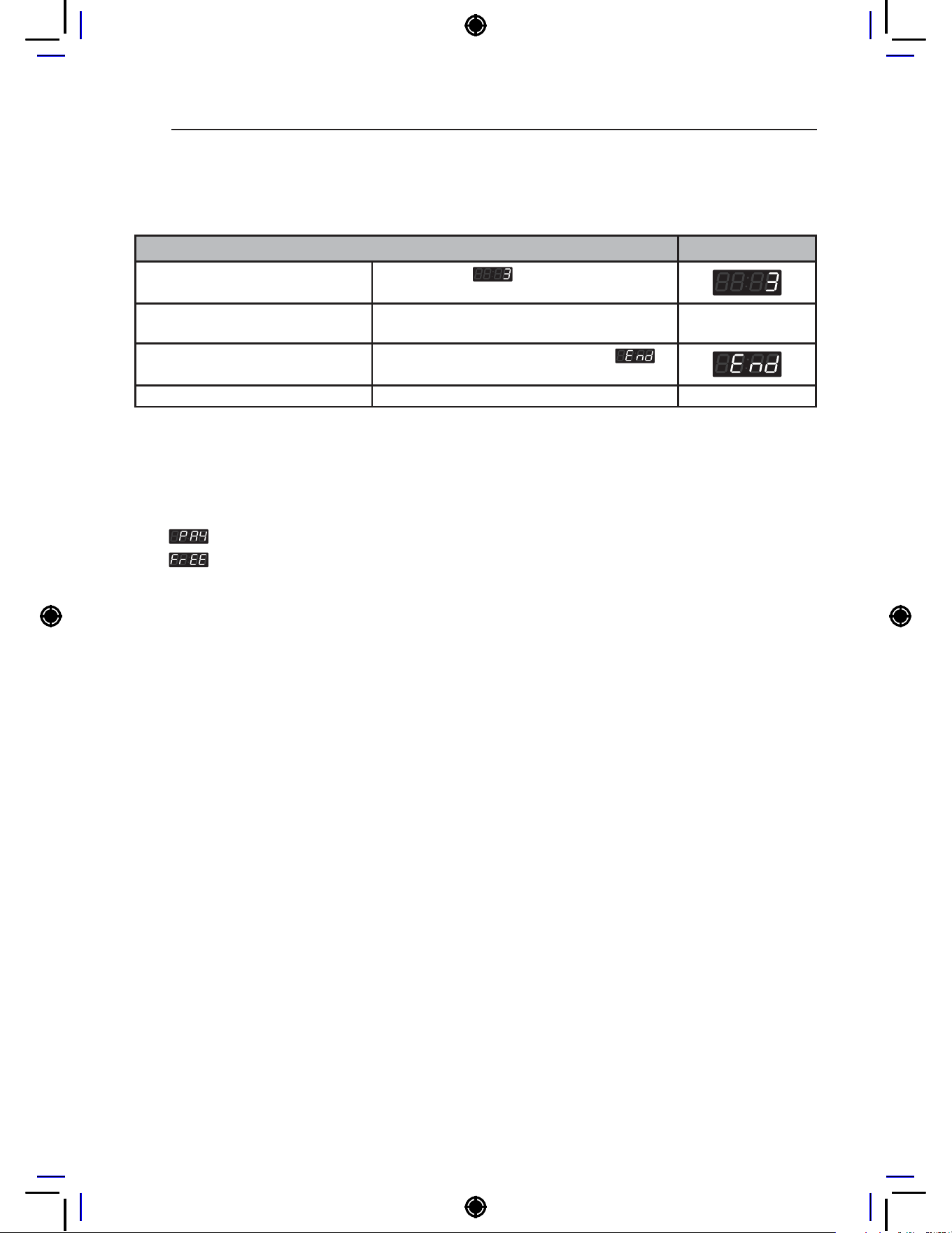
Quick mode setup
Quick mode setup can be used to enable/disable the use quick cycle.
Quick Mode Setup Display
Enter SVC mode
Press 1st button
Press 2nd button
Press start button
Press 2nd button or 3rd button Until display shows
Press start button
Press 2nd button or 3rd button Until display shows
Press start button
Select the setting you want
Button functions:
Start button = Select
1st button = Go back a step
2nd button = Move up or
increase value
3rd button = Move down or
decrease value
Press Start to enable or disable The next menu setting will be displayed.
54
PROGRAMING MODE – SETUP MODE
7-7.
Hygiene cycle entry button setup
Hygiene cycle entry button setup can be used to set the function of the 1st button.
Hygiene Cycle Entry Button Setup Display
Enter SVC mode
Press 1st button
Press 2nd button
Press start button
Press 2nd button or 3rd button Until display shows
Press start button
Press 2nd button or 3rd button Until display shows
Press start button
Select the setting you want
Button functions:
Start button = Select
1st button = Go back a step
2nd button = Move up or
increase value
3rd button = Move down or
decrease value
Press Start to enable or disable The next menu setting will be displayed.
NOTE
• Setting
to will make the 1st button function as Hygiene cycle.
• Setting
to will make the 1st button function as Hot cycle.
• The hygiene cycle is a heating cycle that, like tub clean cycle, may shut down if several units are
operated simultaneously.
• This setup is only available in NON HEATER type
55
PROGRAMING MODE – SETUP MODE
HEATER
7-8.
UE Error Display Setup
The UE error display set up is used to enable or disable the UE function.
UE Error Display Setup Display
Enter SVC mode
Press 1st button
Press 2nd button
Press start button
Press 2nd button or 3rd button Until display shows
Press start button
Press 2nd button or 3rd button Until display shows
Press start button
Select the setting you want
Button functions:
Start button = Select
1st button = Go back a step
2nd button = Move up or
increase value
3rd button = Move down or
decrease value
Press Start to enable or disable The next menu setting will be displayed.
NOTE
•
UE will not displayed.
•
UE will be displayed If the spin entry is failed within displayed time+cut off time( ). After UE
is displayed press the start button one time and the machine will return to standby mode. The spin only
entry feature will be active for this cycle following a UE. Refer to 7-3 of this manual on how to use the
Spin only easy entry feature.
56
PROGRAMING MODE – SETUP MODE
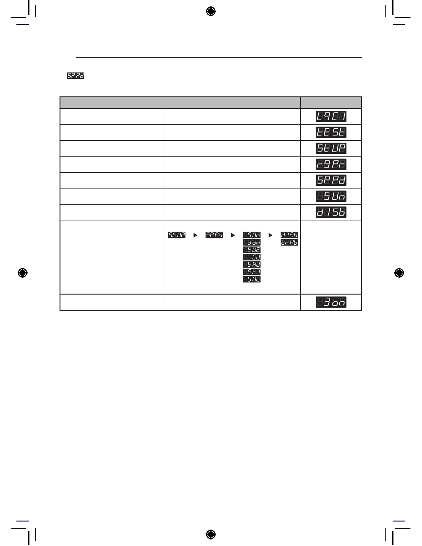
8. Special Price Day Setup
Special Price Day Setup can be used to select which days to apply special prices.
Special Price Day Setup Display
Enter SVC mode
Press 1st button
Press 2nd button
Press start button
Press 2nd button or 3rd button Until display shows
Press start button
Press Start button
Select the setting you want
Button functions:
Start button = Select
1st button = Go back a step
2nd button = Move up or
increase value
3rd button = Move down or
decrease value
Press Start to enable or disable The next menu setting will be displayed.

57
PROGRAMING MODE – SETUP MODE
HEATER
9. Special Price Beginning Time Setup
Special Price Beginning Time Setup can be used to set the start time of special prices.
Special Price Beginning Time Setup Display
Enter SVC mode
Press 1st button
Press 2nd button
Press start button
Press 2nd button or 3rd button Until display shows
Press start button
Select the setting you want
Button functions:
Start button = Select
1st button = Go back a step
2nd button = Move up or
increase value
3rd button = Move down or
decrease value
Press Start to set time The next menu setting will be displayed.
NOTE
• Make sure to set up the Time feature before using this feature.
• Range : 0~23 hr
• Increments : 1

58
PROGRAMING MODE – SETUP MODE
10. Special Price Ending Time Setup
Special Price Ending Time Setup can be used to set the end time for special prices.
Special Price Ending Time Setup Display
Enter SVC mode
Press 1st button
Press 2nd button
Press start button
Press 2nd button or 3rd button Until display shows
Press start button
Select the setting you want
Button functions:
Start button = Select
1st button = Go back a step
2nd button = Move up or
increase value
3rd button = Move down or
decrease value
Press Start to set time The next menu setting will be displayed.
NOTE
• Range : 1~24 hr
• Increments : 1
59
PROGRAMING MODE – SETUP MODE
HEATER
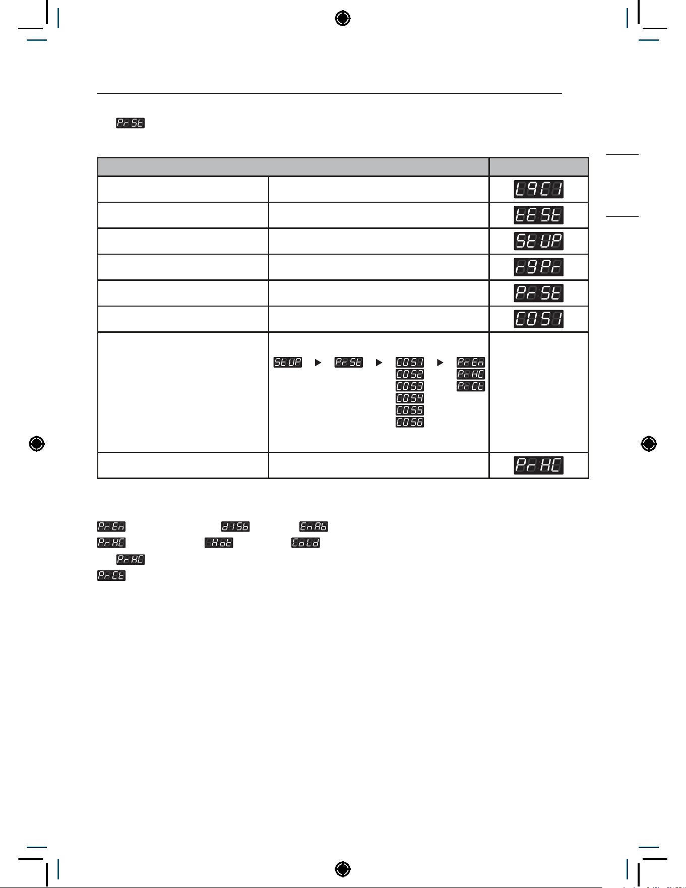
11. Prewash Setup
Prewash Setup can be used to set option for prewash.
Prewash Setup Display
Enter SVC mode
Press 1st button
Press 2nd button
Press start button
Press 2nd button or 3rd button Until display shows
Press start button
Select the setting you want
Button functions:
Start button = Select
1st button = Go back a step
2nd button = Move up or
increase value
3rd button = Move down or
decrease value
Press Start to set option The next menu setting will be displayed.
NOTE
: Prewash available( : disable / : enable)
: Prewash valve( : hot valve / : cold valve)
−
is used only on single type model.
: Prewash time(Range : 4~8)

60
PROGRAMING MODE – SETUP MODE
12. Wash Time Setup
Wash Time Setup can be used to set the duration of the wash process.
Wash Time Setup Display
Enter SVC mode
Press 1st button
Press 2nd button
Press start button
Press 2nd button or 3rd button Until display shows
Press start button
Select the setting you want
Button functions:
Start button = Select
1st button = Go back a step
2nd button = Move up or
increase value
3rd button = Move down or
decrease value
Press Start to set time The next course setting will be displayed.
NOTE
• Range : 0~30 min
• Increments : 1
• COS1 : 90°C (194°F)
• COS2 : 75°C (167°F)
• COS3 : 60°C (140°F)
• COS4 : 40°C (104°F)
• COS5 : Cold
• COS6 : 30°C (86°F)
61
PROGRAMING MODE – SETUP MODE
HEATER
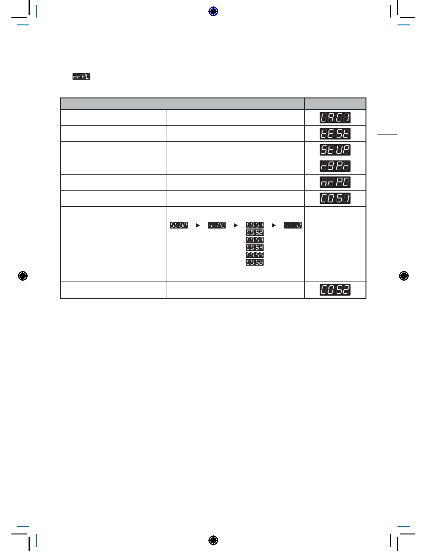
13. Number of Rinses per Cycle Setup
Number of Rinses per Cycle Setup can be used to set number of rinses for one cycle.
Number of Rinses per Cycle Setup Display
Enter SVC mode
Press 1st button
Press 2nd button
Press start button
Press 2nd button or 3rd button Until display shows
Press start button
Select the setting you want
Button functions:
Start button = Select
1st button = Go back a step
2nd button = Move up or
increase value
3rd button = Move down or
decrease value
Press Start to set the number of
cycles
The next course setting will be displayed.
NOTE
• Range : 1~5
• Increments : 1
• COS1 : 90°C (194°F)
• COS2 : 75°C (167°F)
• COS3 : 60°C (140°F)
• COS4 : 40°C (104°F)
• COS5 : Cold
• COS6 : 30°C (86°F)
62
PROGRAMING MODE – SETUP MODE
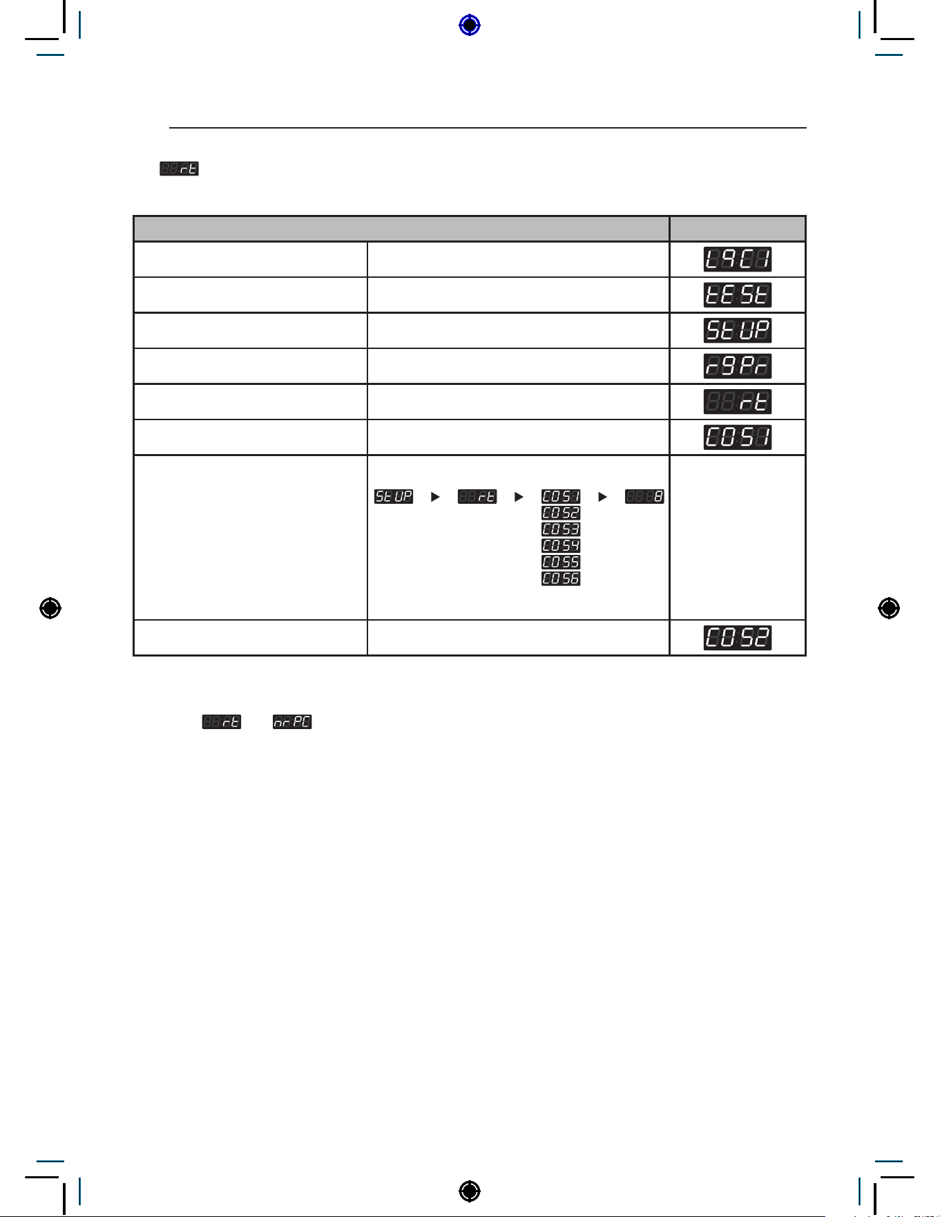
14. Rinse Time Setup
Rinse Time Setup can be used to set the duration of one rinse.
Rinse Time Setup Display
Enter SVC mode
Press 1st button
Press 2nd button
Press start button
Press 2nd button or 3rd button Until display shows
Press start button
Select the setting you want
Button functions:
Start button = Select
1st button = Go back a step
2nd button = Move up or
increase value
3rd button = Move down or
decrease value
Press Start to set time The next course setting will be displayed.
NOTE
• Multiple
and to calculate total rinse process time
• Range : 8~16 min
• Increments : 1
• COS1 : 90°C (194°F)
• COS2 : 75°C (167°F)
• COS3 : 60°C (140°F)
• COS4 : 40°C (104°F)
• COS5 : Cold
• COS6 : 30°C (86°F)

63
PROGRAMING MODE – SETUP MODE
HEATER
15. Top Spin Speed Setup
Top Spin Speed Setup can be used to set the maximum RPM for the spin process.
Top Spin Speed Setup Display
Enter SVC mode
Press 1st button
Press 2nd button
Press start button
Press 2nd button or 3rd button Until display shows
Press start button
Select the setting you want
Button functions:
Start button = Select
1st button = Go back a step
2nd button = Move up or
increase value
3rd button = Move down or
decrease value
Press Start to set the number The next course setting will be displayed.
NOTE
• Range : 0~6
• Increments : 1
• COS1 : 90°C (194°F)
• COS2 : 75°C (167°F)
• COS3 : 60°C (140°F)
• COS4 : 40°C (104°F)
• COS5 : Cold
• COS6 : 30°C (86°F)
0 : 1200RPM
1 : 1000 RPM
2 : 900 RPM
3 : 800 RPM
4 : 700 RPM
5 : 600 RPM
6 : 500 RPM

64
PROGRAMING MODE – SETUP MODE
16. Water Level Setup
Water Level Setup can be used to set the water supply level.
Water Level Setup Display
Enter SVC mode
Press 1st button
Press 2nd button
Press start button
Press 2nd button or 3rd button Until display shows
Press start button
Select the setting you want
Button functions:
Start button = Select
1st button = Go back a step
2nd button = Move up or
increase value
3rd button = Move down or
decrease value
Press Start to set the level The next course setting will be displayed.
NOTE
• COS1 : 90°C (194°F)
• COS2 : 75°C (167°F)
• COS3 : 60°C (140°F)
• COS4 : 40°C (104°F)
• COS5 : Cold
• COS6 : 30°C (86°F)
• Water level frequency
• High : 23.0 KHz
• Middle : 23.3 KHz (cold course : 23.5 KHz)
• Low : 23.8 KHz
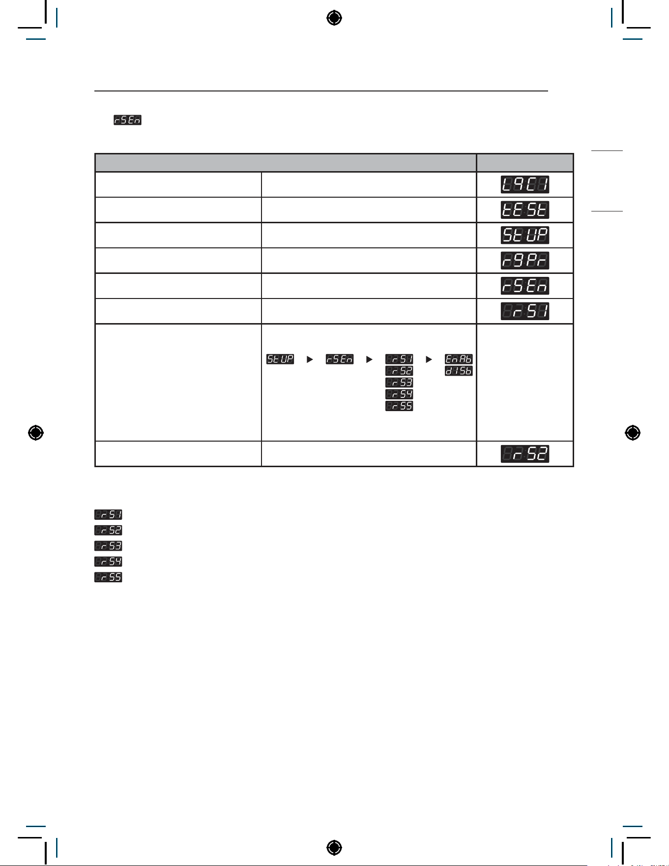
65
PROGRAMING MODE – SETUP MODE
HEATER
17. Rinse Spin Setup
Rinse Spin Setup can be used to enable/disable spin during rinse cycle.
Rinse Spin Setup Display
Enter SVC mode
Press 1st button
Press 2nd button
Press start button
Press 2nd button or 3rd button Until display shows
Press start button
Select the setting you want
Button functions:
Start button = Select
1st button = Go back a step
2nd button = Move up or
increase value
3rd button = Move down or
decrease value
Press Start to enable or disable The next course setting will be displayed.
NOTE
: 1st rinse spin skip
: 2nd rinse spin skip
: 3rd rinse spin skip
: 4th rinse spin skip
: 5th rinse spin skip

66
PROGRAMING MODE – SETUP MODE
18. Drop Count Setup
Drop Count Setup can be used to set the number of drop counts. Drops occur while the machine
checks for balancing of the load as the cycle enters higher RPM.
Drop Count Setup Display
Enter SVC mode
Press 1st button
Press 2nd button
Press start button
Press 2nd button or 3rd button Until display shows
Press start button
Select the setting you want
Button functions:
Start button = Select
1st button = Go back a step
2nd button = Move up or
increase value
3rd button = Move down or
decrease value
Press Start to set the number The next menu setting will be displayed.
NOTE
• Drop counts 25~145: After dropping the selected amount of counts, UE will not occur. The cycle will
end immediately or after spinning at a low RPM.
• Drop counts 150: After dropping the selected amount of counts, UE will occur. The cycle will end after
shut down time. Refer to How to set shut down time after UE.

67
PROGRAMING MODE – SETUP MODE
HEATER
19. Rinse Spin Drop Count Setup
Rinse Spin Drop Count Setup can be used to set the drop count for each rinse spin. Drops occur
while the machine checks for balancing of the load as the cycle enters higher RPM.
Rinse Spin Drop Count Setup Display
Enter SVC mode
Press 1st button
Press 2nd button
Press start button
Press 2nd button or 3rd button Until display shows
Press start button
Select the setting you want
Button functions:
Start button = Select
1st button = Go back a step
2nd button = Move up or
increase value
3rd button = Move down or
decrease value
Press Start to set the number The next menu setting will be displayed.
NOTE
• Range : 5~15
• Increments : 1
• If unable to reach target RPM within set number of drops, cycle will continue to next step.
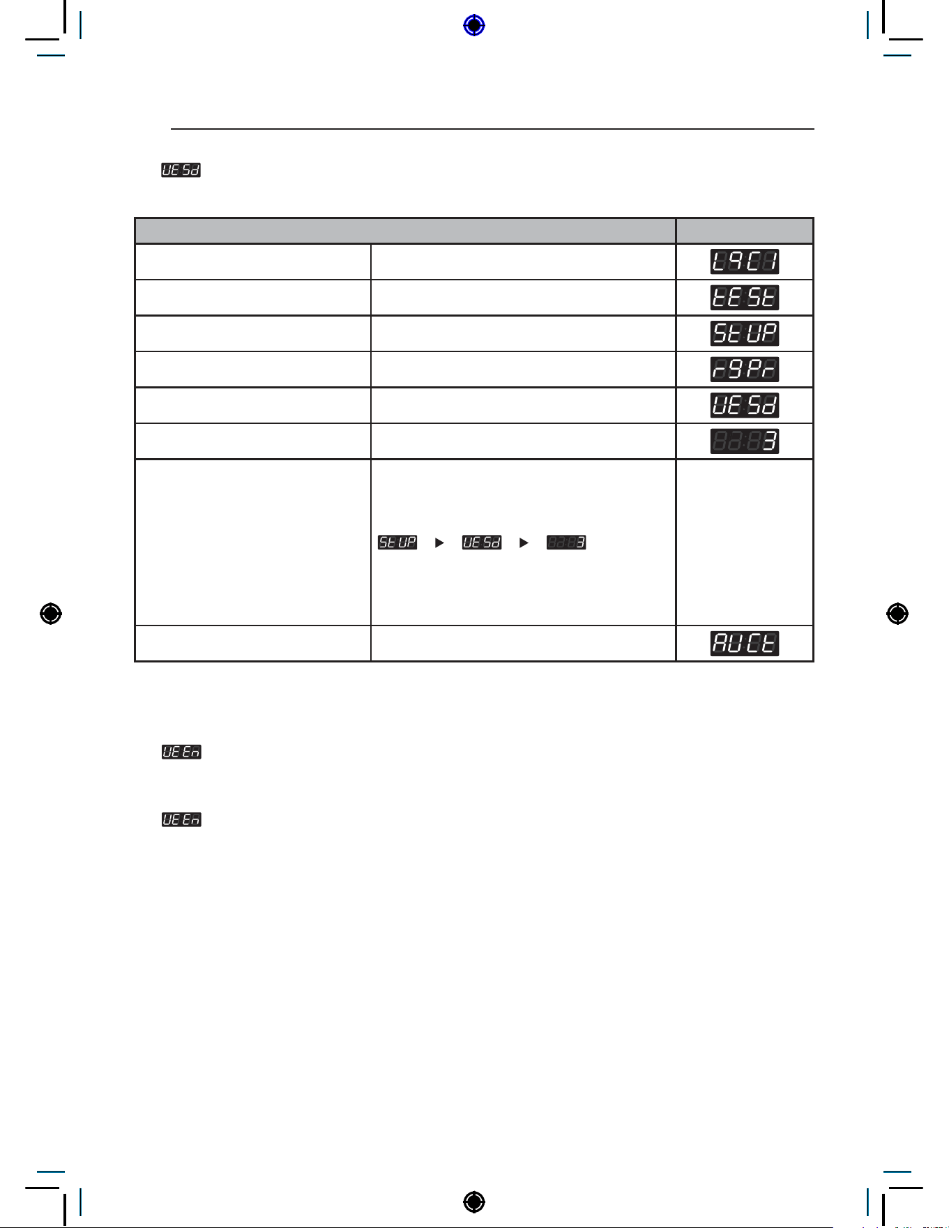
68
PROGRAMING MODE – SETUP MODE
20. UE Shutdown Setup
UE Shutdown Setup can be used to set the time to display UE until the cycle ends.
UE Shutdown Setup Display
Enter SVC mode
Press 1st button
Press 2nd button
Press start button
Press 2nd button or 3rd button Until display shows
Press start button
Select the setting you want
Button functions:
Start button = Select
1st button = Go back a step
2nd button = Move up or
increase value
3rd button = Move down or
decrease value
Press Start to set the time The next menu setting will be displayed.
NOTE
• Range : 0~10 min
• If
setting is disabled,
− 0 : UE will remain until user opens door, redistributes clothes, and starts up spin process again.
− 1~10 : Cycle will end after set time.
• If
setting is enabled,
− 0 : UE will remain until the “Start” button in selected.
− 1~10 : Washer returns to standby mode after the designated programmed time.

69
PROGRAMING MODE – SETUP MODE
HEATER
21. Auto Dosing Pump Time Setup
Auto Dosing Pump Time Setup can be used to set the pump activation duration for each channel per
course.
Auto Dosing Pump Time Setup Display
Enter SVC mode
Press 1st button
Press 2nd button
Press start button
Press 2nd button or 3rd button Until display shows
Press start button
Select the setting you want
Button functions:
Start button = Select
1st button = Go back a step
2nd button = Move up or
increase value
3rd button = Move down or
decrease value
Press Start to set the time The next channel setting will be displayed.
CH Detergent Range (s) Input period
a
Pre-wash 0~20 Pre-wash phase
b
Main wash 0~20 Main wash phase
c
Bleach 0~10
Main wash (Remaining washing
time : 5 Minutes)
d
Softener 0~20 Final rinse phase
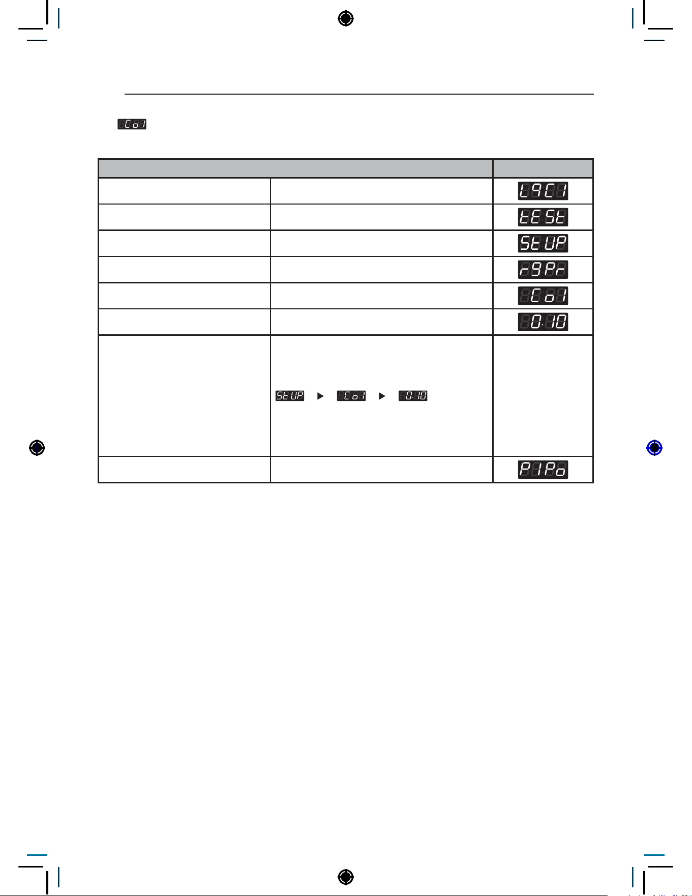
70
PROGRAMING MODE – SETUP MODE
22. Coin 1 Value Setup
Coin 1 Value Setup can be used to set the value of each coin signal received.
Coin1 Value Setup Display
Enter SVC mode
Press 1st button
Press 2nd button
Press start button
Press 2nd button or 3rd button Until display shows
Press start button
Select the price you want
Button functions:
Start button = Select
1st button = Go back a step
2nd button = Move up or
increase value
3rd button = Move down or
decrease value
Press Start to set the price The next menu setting will be displayed.
NOTE
• Range : 0.1~10.00
• Increment : 0.1

71
PROGRAMING MODE – SETUP MODE
HEATER
23. Penny Increment Pricing Offset Setup
Penny Increment Pricing Offset Setup can be used to set additional cent increase when card is
used.
Penny Increment Pricing Offset Setup Display
Enter SVC mode
Press 1st button
Press 2nd button
Press start button
Press 2nd button or 3rd button Until display shows
Press start button
Select the price you want
Button functions:
Start button = Select
1st button = Go back a step
2nd button = Move up or
increase value
3rd button = Move down or
decrease value
Press Start to set the price The next menu setting will be displayed.
NOTE
• Range : 0~4
•
Penny increment pricing offset is available only in card type. It hasn’t affected the coin type’s
price setting.

72
PROGRAMING MODE – SETUP MODE
24. Beep Volume Setup
Beep Volume Setup can be used to set the sound level of the machine.
Beep Volume Setup Display
Enter SVC mode
Press 1st button
Press 2nd button
Press start button
Press 2nd button or 3rd button Until display shows
Press start button
Select the setting you want
Button functions:
Start button = Select
1st button = Go back a step
2nd button = Move up or
increase value
3rd button = Move down or
decrease value
Press Start to set the sound level The next menu setting will be displayed.

73
PROGRAMING MODE – SETUP MODE
HEATER
25. Standby Return Time Setup
Standby Return Time Setup can be used to set how long the input payment is held until the machine
resets to standby mode.
Standby Return Time Setup Display
Enter SVC mode
Press 1st button
Press 2nd button
Press start button
Press 2nd button or 3rd button Until display shows
Press start button
Select the setting you want
Button functions:
Start button = Select
1st button = Go back a step
2nd button = Move up or
increase value
3rd button = Move down or
decrease value
Press Start to set the time The next menu setting will be displayed.
NOTE
• 0 : Holds input payment permanently.
• 1~180 : Holds input payment for selected amount of time, then returns to standby mode.
•
: Standby return time setup is available only in coin type.

74
PROGRAMING MODE – SETUP MODE
26. Type
Type can be used to set the machine’s various type settings.
Type Display
Enter SVC mode
Press 1st button
Press 2nd button
Press start button
Press 2nd button or 3rd button Until display shows
Select the setting you want
Button functions:
Start button = Select
1st button = Go back a step
2nd button = Move up or
increase value
3rd button = Move down or
decrease value
NOTE
: Product type
: Currency type
: Vend type
: Card reader type
: Coin meter type
: Heater type
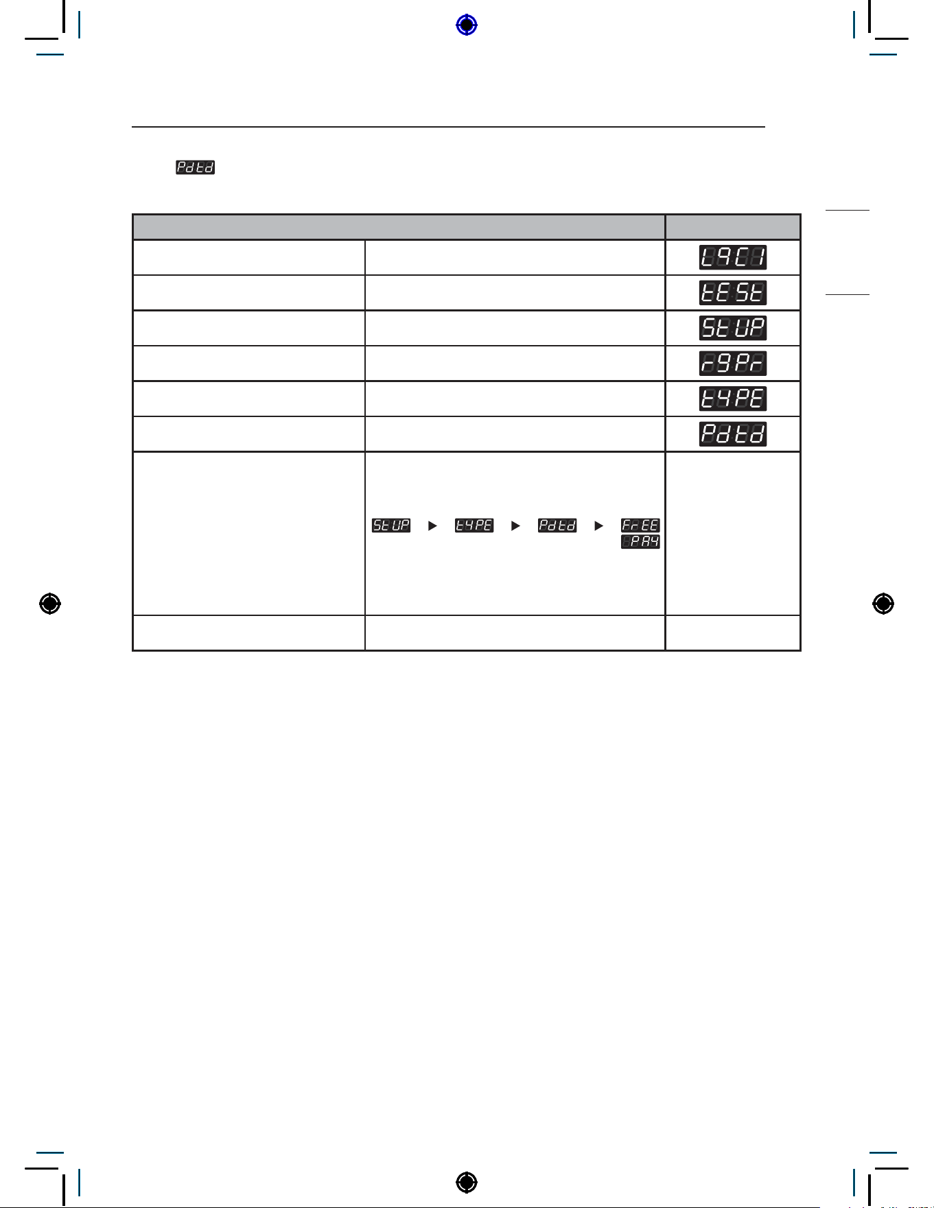
75
PROGRAMING MODE – SETUP MODE
HEATER
26-1. Product Type Setup
Product Type Setup can be used to set the machine’s payment type (Pay or Free)
Product Type Setup Display
Enter SVC mode
Press 1st button
Press 2nd button
Press start button
Press 2nd button or 3rd button Until display shows
Press Start button
Select the setting you want
Button functions:
Start button = Select
1st button = Go back a step
2nd button = Move up or
increase value
3rd button = Move down or
decrease value
Press Start to set the type Display returns to standby mode.
NOTE
• PAY : Coin/Card
• FrEE : On Premise Laundry
• Issues may occur if certain large items are loaded after changing from Free type to Pay type.
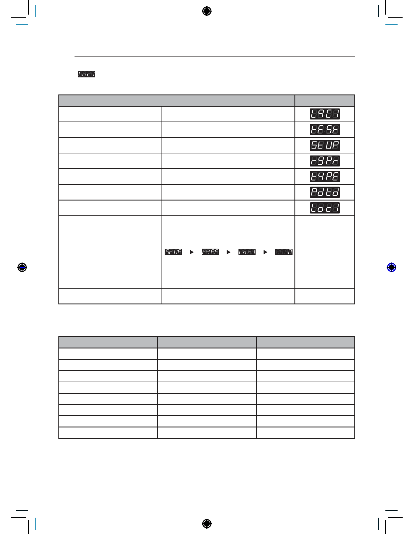
76
PROGRAMING MODE – SETUP MODE
26-2. Currency Type Setup
Currency Type Setup can be used to set the country and its currency
Currency Type Setup Display
Enter SVC mode
Press 1st button
Press 2nd button
Press start button
Press 2nd button or 3rd button Until display shows
Press Start button
Press 2nd button or 3rd button Until display shows
Select the setting you want
Button functions:
Start button = Select
1st button = Go back a step
2nd button = Move up or
increase value
3rd button = Move down or
decrease value
Press Start to set the type Display returns to standby mode.
NOTE
Country (Loc1) Range Increments
England (0) 0~10.00 0.10
Australia (1) 0~10.00 1.00
USA (2) 0~9.95 0.05
China (3) 0~199 1
Korea (4) 0~9500 100
Japan (5) 0~9500 100
Canada (6) 0~9.95 0.05
Philippines (7) 0~995 5

77
PROGRAMING MODE – SETUP MODE
HEATER
26-3. Vend Type Setup
Vent Type Setup can be used to set the payment type (Coin/Card/Mobile pay).
Vend Type Setup Display
Enter SVC mode
Press 1st button
Press 2nd button
Press start button
Press 2nd button or 3rd button Until display shows
Press Start button
Press 2nd button or 3rd button Until display shows
Select the setting you want
Button functions:
Start button = Select
1st button = Go back a step
2nd button = Move up or
increase value
3rd button = Move down or
decrease value
Press Start to set the type Display returns to standby mode.

78
PROGRAMING MODE – SETUP MODE
26-4. Card Reader Type Setup
Card Reader Type can be used to set the card reader company.
Card Reader Type Setup Display
Enter SVC mode
Press 1st button
Press 2nd button
Press start button
Press 2nd button or 3rd button Until display shows
Press Start button
Press 2nd button or 3rd button Until display shows
Select the setting you want
Button functions:
Start button = Select
1st button = Go back a step
2nd button = Move up or
increase value
3rd button = Move down or
decrease value
Press Start to set the type Display returns to standby mode.
NOTE
• 0 : Greenwald
• 1 : ESD

79
PROGRAMING MODE – SETUP MODE
HEATER
26-5. Coin Drop Type Setup
Coin Drop Type can be used to set the coin pulse signal setting for coin drops.
Coin Drop Type Setup Display
Enter SVC mode
Press 1st button
Press 2nd button
Press start button
Press 2nd button or 3rd button Until display shows
Press Start button
Press 2nd button or 3rd button Until display shows
Select the setting you want
Button functions:
Start button = Select
1st button = Go back a step
2nd button = Move up or
increase value
3rd button = Move down or
decrease value
Press Start to set the type Display returns to standby mode.
NOTE
• Coin pulse
• 0 : 50ms : ESD, Greenwald, Munzprufer
• 1 : 100ms : Korea

80
PROGRAMING MODE – SETUP MODE
26-6. Heater type setup
Heater type setup can be used to set machine’s type. (heater/non heater course)
Heater Type Setup Display
Enter SVC mode
Press 1st button
Press 2nd button
Press start button
Press 2nd button or 3rd button Until display shows
Press Start button
Press 2nd button or 3rd button Until display shows
Select the setting you want
Button functions:
Start button = Select
1st button = Go back a step
2nd button = Move up or
increase value
3rd button = Move down or
decrease value
Press Start to set the type Display returns to standby mode.
NOTE
• On : Heater
• OFF : Non heater
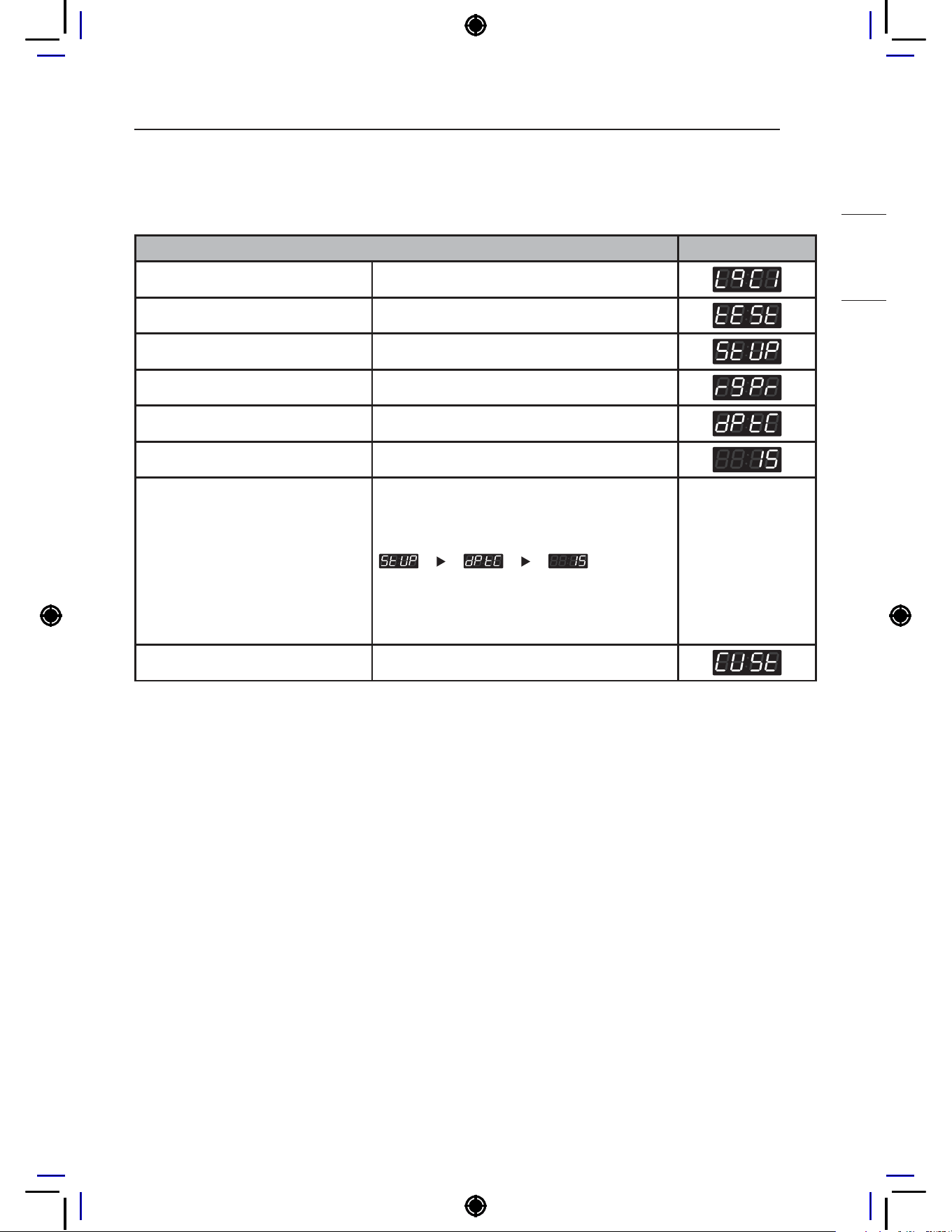
81
PROGRAMING MODE – SETUP MODE
HEATER
27. Max Surpassed Cycle Time Setup
Cut off time is how long the machine can run after the display time has been reached. This feature
allows the adjustment of the cut off time between 1 and 15 minutes.
Max Surpassed Cycle Time Setup Display
Enter SVC mode
Press 1st button
Press 2nd button
Press start button
Press 2nd button or 3rd button Until display shows
Press Start button
Select the setting you want
Button functions:
Start button = Select
1st button = Go back a step
2nd button = Move up or
increase value
3rd button = Move down or
decrease value
Press Start to set the time. The next menu setting will be displayed.
NOTE
• Range : 1~15 min
• Increments : 1
• The washer will try and complete the entire cycle in the allotted display time. However, in the case of
an off balance load or too much soap, the washer will use the extra cut off time to balance or remove
excess soap before ending the cycle.

82
PROGRAMING MODE – SETUP MODE
28. Custom Program Setup
Custom Program can be used to create up to 20 different customized courses.
Custom Program Setup Display
Enter SVC mode
Press 1st button
Press 2nd button
Press start button
Press 2nd button or 3rd button Until display shows
Press Start button
Select the setting you want
Button functions:
Start button = Select
1st button = Go back a step
2nd button = Move up or
increase value
3rd button = Move down or
decrease value
Press Start to set
NOTE
: only available in FrEE type.
: Total number of custom courses (1~20)
: Select base course
: Wash Time
: Number of Rinse per Cycle
: Rinse Time
: Top Spin Speed
: Water Level
: Rinse Spin Only, Spin Only
: Rinse Spin
: Auto Dosing Pump Time
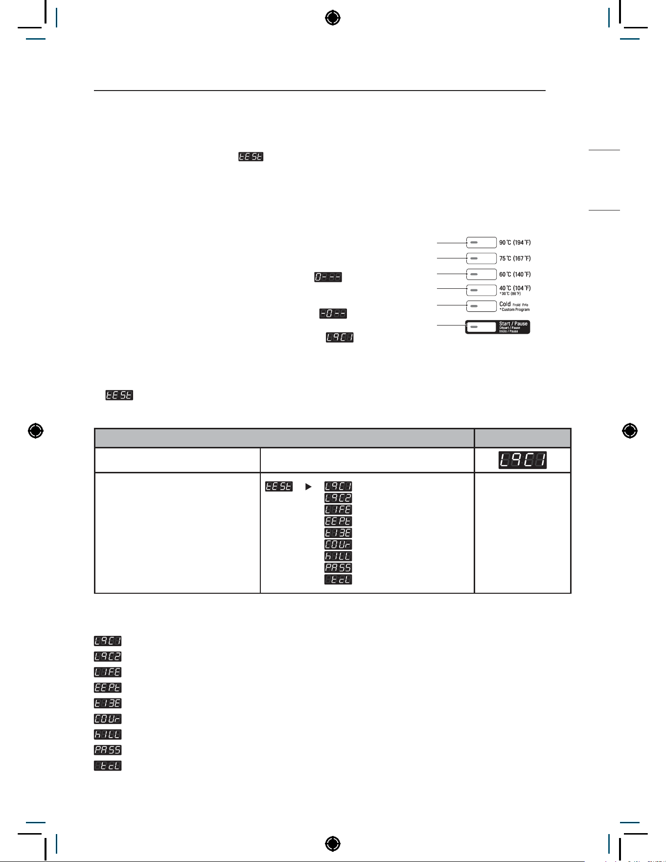
83
Programing Mode – Test Mode
HEATER
Programing Mode – Test Mode
Diagnostic tests:
(display)
This program has been added for testing the washer and detecting errors.
How to enter Programming mode:
• Coin type – Turn on/off the toggle switch.
• Card type – Insert the service card.
• All types –
1
Press the 1st & 3rd button at the same time.
2
Press the 2nd & 3rd buttons to toggle numbers. Then,
press the 4th button to move to the next digit.
3
Press the Start button to finish password input.
* Default Password : 3000
<Control Panel Button>
1st
2nd
3rd
4th
5th
Start
1. Test
Test features can be used to check and change various machine settings.
Test mode Display
Enter SVC mode
Select the feature you want
Button functions:
Start button = Select
1st button = Go back a step
2nd button = Move up or
increase value
3rd button = Move down or
decrease value
NOTE
: Diagnostic Test 1
: Factory Use (Do not Use)
: Factory Use (Do not Use)
: Factory Reset
: Time Setting
: Courtesy Cycle
: Cycle Kill
: Password Setup
: Tub Clean Course
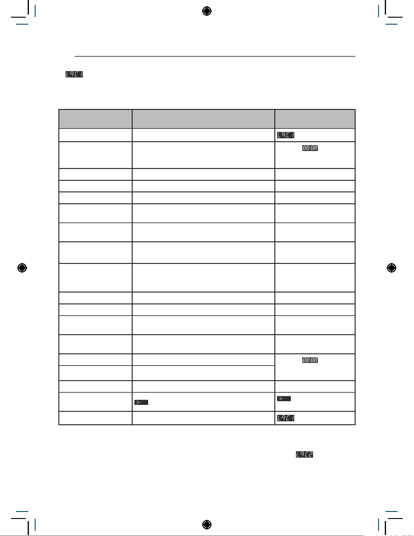
84
Programing Mode – Test Mode
2. Diagnostic Test
Diagnostic Test can be used to check functionality of various machine parts.
Press Start to move through the check points.
Number of times the
Start button is pressed
Check point Display
0 Enter SVC mode
1 Turns on all lamps and locks the door
Displays
, 1U:XX,
1g:XX, 10:XX, 1C:XX
alternately (Version)
2 Tumble clockwise rpm (40~50)
3 Low speed spin rpm (600
4 High speed spin rpm (1200)
5 Inlet valve for main water turns on
Water level frequency
(255~)
6 Inlet valve for hot water turns on
Water level frequency
(255~)
7
Inlet valve for atomizing turns on (Single model)
Inlet valve for softener turns on (Stack model)
Water level frequency
(255~)
8
Inlet valve for bleach turns on (Single model)
Inlet valve for atomizing/bleach turns on (Stack
model)
Water level frequency
(255~)
9 Tumble counter clockwise rpm (40~50)
10 Heater turns on Displays water temperature
11 Circulation pump turns on
Water level frequency
(255~)
12 Drain pump turns on
Water level frequency
(255~)
13 All lamps turn on
Displays
, 1U:XX,
1g:XX, 10:XX, 1C:XX
alternately (Version)
14 Button check
15 High speed spin rpm (1200)
16
PDA signal check
this function is not
applied in this machine
17
NOTE
• Make sure the drum is empty when diagnostic test is being performed. Do not use
.
• RPM notation is displayed except for the last number when it is more than a hundred.
(i.e. 1200 rpm is displayed as 120)
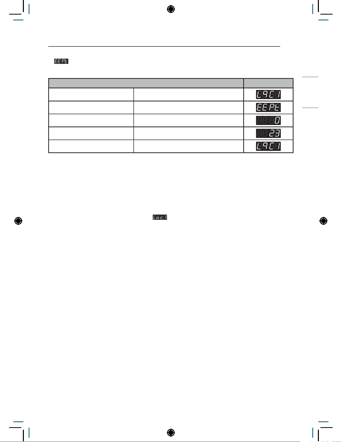
85
Programing Mode – Test Mode
HEATER
3. Factory Reset
Factory Reset is used to reset the machine to default settings.
Factory Reset Display
Enter SVC mode
Press 2nd button or 3rd button Until display shows
Press Start button
Press 2nd button Until display shows
Press Start button
NOTE
• All settings return to default.
• Wash time : 20 minutes
• Rinse cycle : Twice
• Top spin speed : 1000 rpm
• Price setting varies by country
• After Factory Reset, set your country from
mode.
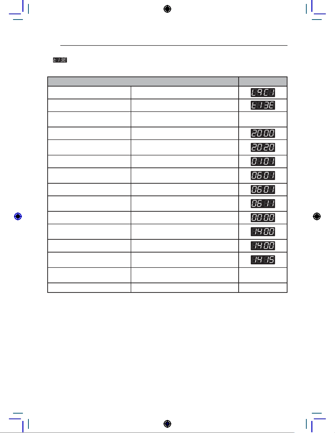
86
Programing Mode – Test Mode
4. Time Setup
Time Setup can be used to set the current year, month, day, hour, and minute.
Time Setup Display
Enter SVC mode
Press 2nd button or 3rd button Until display shows
Press Start button
Display shows you 2000(Year) → 0101(Month/
Date) → Sat(Day) → 0000(Time(24hr))
Press Start button
Press 2nd button or 3rd button
Until display shows the year you want (i.e.
2020)
Press Start button
Press 2nd button or 3rd button
Until display shows the month you want in the
left two digits (i.e. June = 0601)
Press Start button
Press 2nd button or 3rd button
Until display shows the day you want in the
right two digits (i.e. June 11th = 0611)
Press Start button
Press 2nd button or 3rd button
Until display shows the hour you want (i.e.
2:00 PM = 1400)
Press Start button
Press 2nd button or 3rd button
Until displays shows the minute you want (i.e.
2:15 PM = 1415)
Press Start button
Display shows you 2000(Year) → 0101(Month/
Date) → Sat(Day) → 0000(Time(24hr))
Press 1st button Until display returns to standby mode
NOTE
• Time is displayed in military time format.
• Time Setup must be set to use Special Day Price feature.
• When the machine is powered off, Time Setup is reset to default.
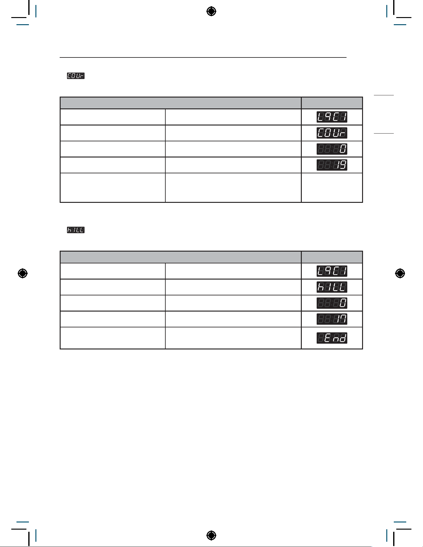
87
Programing Mode – Test Mode
HEATER
5. Courtesy Cycle
Courtesy Cycle is a free cycle given to customers for Pay Type machines.
Courtesy Cycle Display
Enter SVC mode
Press 2nd button or 3rd button Until display shows
Press Start button
Press 2nd button Until display shows
Press Start button
Machine is ready to use.
User can choose desired course and press
Start.
6. Kill Cycle
Kill Cycle is used to end the currently operating cycle.
Cycle Kill Display
Enter SVC mode
Press 2nd button or 3rd button Until display shows
Press Start button
Press 2nd button Until display shows
Press Start button
Machine is ready to use.
User can choose desired course and press Start.
NOTE
• Only works for machine that is currently operating.
• Cycle can be ended with Cycle Kill Card for Card Type machines.
• Easy entry : Press and hold the start button for at least 3 seconds.
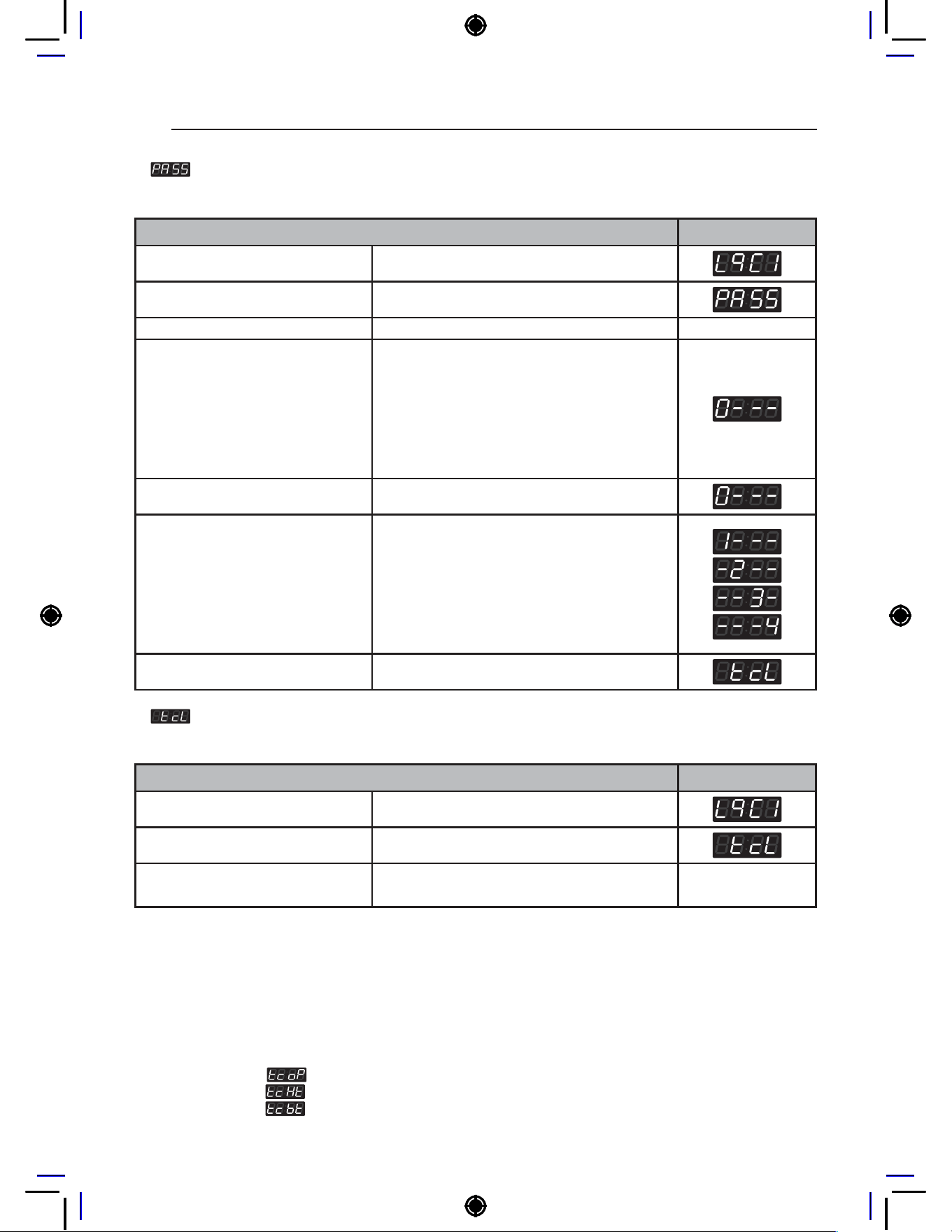
88
Programing Mode – Test Mode
7. Password Setup
Password Setup can be used to change the password to enter Service mode.
Password Setup Display
Enter SVC mode
Press 2nd button or 3rd button Until display shows
Press Start button
Button functions: Start button =
Select
1st button = Go back a step
2nd button = Move up or
increase value
3rd button = Move down or
decrease value
Input current password
Default Password : 3000
1
Press the 2nd & 3rd buttons to toggle
numbers.
2
Press the 4th button to move to the next digit.
Press Start button
Button functions: Start button =
Select
1st button = Go back a step
2nd button = Move up or
increase value
3rd button = Move down or
decrease value
Input new password (i.e. 1234)
1
Press the 2nd & 3rd buttons to toggle
numbers.
2
Press the 4th button to move to the next digit.
Press Start button New password is set
8. Tub Clean Course
Tub Clean Course is used to clean the drum.
Tub Clean Course Display
Enter SVC mode
Press 2nd button or 3rd button Until display shows
Press Start button
Display shows remaining time and starts the
Tub Clean Course.
NOTE
• Machine goes back to standby mode after Tub Clean Course is completed.
• Easy Entry : Press and hold the 1st button and 2nd button for at least 3 seconds.
• Display shows the default number of Tub Clean cycles to run. (Range : 1~3)
• Never load laundry when using Tub Clean Course. Laundry may be damaged or become contaminated.
• Tub Clean Course should be used every 50 cycles.
• Related functions
: Tub Clean Load Detection Setup
: Tub Clean Heater Setup
: Tub Clean Shortcut Button Setup
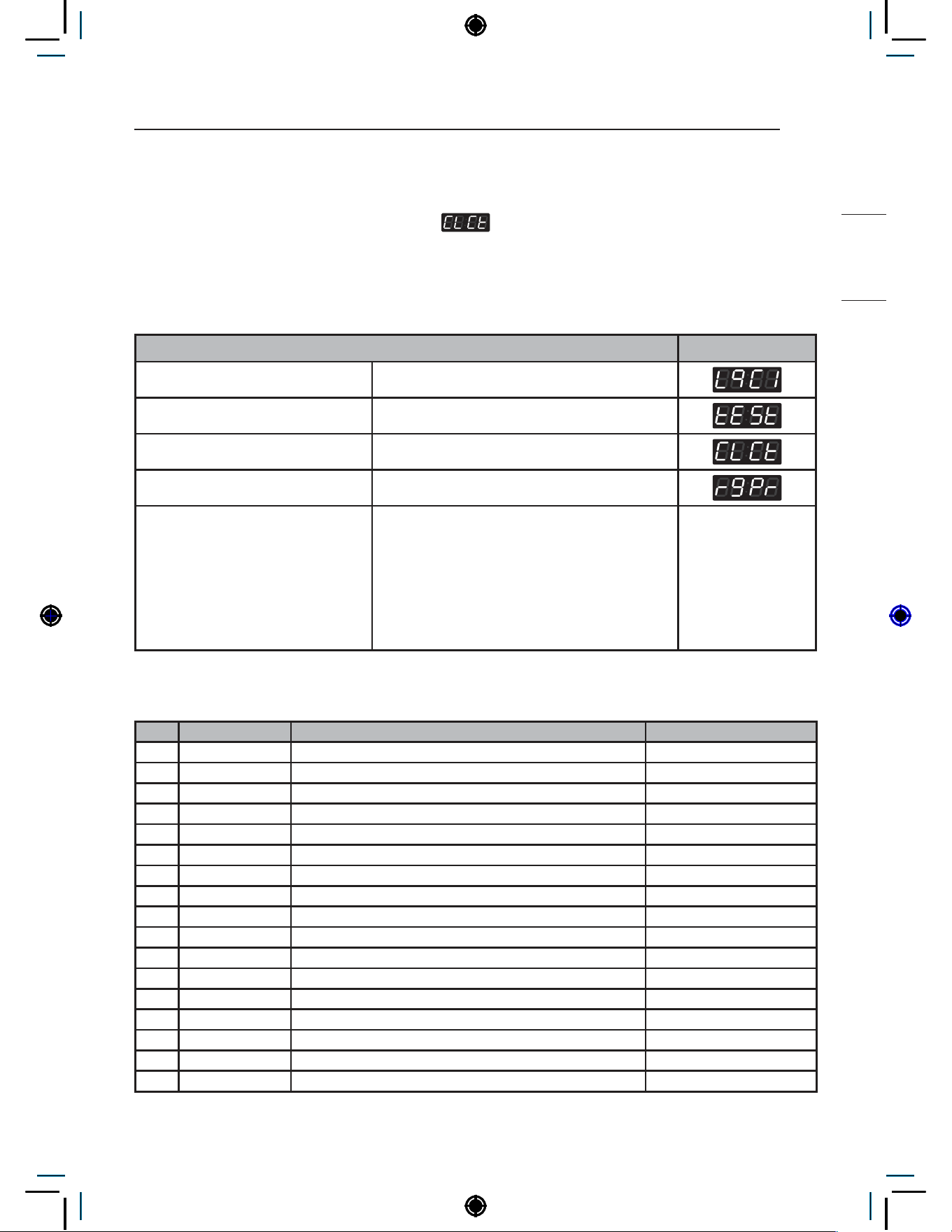
89
Programing Mode – Collect Mode
HEATER
Programing Mode – Collect Mode
Collect information data :
(display)
The washer collects the usage data so that the owner can check various information like number of
various cycles used, how many times card or coins used, etc.
Collect Mode
Collect Mode Display
Enter SVC mode
Press 1st button
Press 2nd button or 3rd button Until display shows
Press Start button
Select the feature you want Start
button = Select
1st button = Go back a step
2nd button = Move up or
increase value
3rd button = Move down or
decrease value
Refer to the follow Collect Mode Data List
Collect Mode Data lists
No. Abbreviation Meaning Description
1 rgPr Regular Price (Default Price)
2 rgP1 Regular COS1 Price
3 rgP2 Regular COS2 Price
4 rgP3 Regular COS3 Price
5 rgP4 Regular COS4 Price
6 rgP5 Regular COS5 Price (for Heater)
7 rgP6 Regular COS6 Price (for Heater)
8 ItrC Interval Regular Total Cycle Count (0~65535)
9 Itr1 Interval Regular COS1 Cycle Count (0~65535)
10 Itr2 Interval Regular COS2 Cycle Count (0~65535)
11 Itr3 Interval Regular COS3 Cycle Count (0~65535)
12 Itr4 Interval Regular COS4 Cycle Count (0~65535)
13 Itr5 Interval Regular COS5 Cycle Count (for Heater) (0~65535)
14 Itr6 Interval Regular COS6 Cycle Count (for Heater) (0~65535)
15 ACrC Accumulated Regular Total Cycle Count (0~65535)
16 ACr1 Accumulated Regular COS1 Cycle Count (0~65535)
17 ACr2 Accumulated Regular COS2 Cycle Count (0~65535)
90
Programing Mode – Collect Mode
18 ACr3 Accumulated Regular COS3 Cycle Count (0~65535)
19 ACr4 Accumulated Regular COS4 Cycle Count (0~65535)
20 ACr5 Accumulated Regular COS5 Cycle Count (for Heater) (0~65535)
21 ACr6 Accumulated Regular COS6 Cycle Count (for Heater) (0~65535)
22 SCPr ‘Add Super Wash’ Price
23 ItSC Interval ‘Add Super Wash’ Usage Count (0~65535)
24 ACSC Accumulated ‘Add Super Wash’ Usage Count (0~65535)
25 AUPr ‘Auto Dosing’ Price
26 ItAU Interval ‘Auto Dosing’ Usage Count (0~65535)
27 ACAU Accumulated ‘Auto Dosing’ Usage Count (0~65535)
28 ItSU Interval ‘Courtesy Cycle’ Usage Count (0~65535)
29 ACSU Accumulated ‘Courtesy Cycle’ Usage Count (0~65535)
30 ItFC Interval ‘Token’ Cycle Count (0~65535)
31 ACFC Accumulated ‘Token’ Cycle Count (0~65535)
32 ACrt Accumulated Run Time (minutes) (0~65535)
33 Itnr Interval No Runs (0~255)
34 Ittb Interval Trouble Cycle Count (0~255)
35 ItPd Interval Power Downs (0~255)
36 Itdd Interval Unauthorized Service Door Openings (0~255)
37 ItUC Interval Unauthorized Coin Vault Openings (0~255)
38 Ittl Interval Total Income (0~65535)
39 ACtl Accumulated Total Income (0~65535)
40 IttC Interval Total Cycle Count (0~65535)
41 ACtC Accumulated Total Cycle Count (0~65535)
42 Itd Interval Money (0~65535)
43 Acd Accumulated Money (0~65535)
44 ItSd Interval ‘Add Super Wash’ Money (0~65535)
45 ACSd Accumulated ‘Add Super Wash’ Money (0~65535)
46 ItA3 Interval ‘Auto Dosing’ Money (0~65535)
47 ACA3 Accumulated ‘Auto Dosing’ Money (0~65535)
48 ACdP Accumulated ‘WaveForce’ Operations (0~65535)
49 ACtL Accumulated ‘Tub Clean Course’ Cycle Count (0~65535)
50 ACPC Accumulated ‘Pre Clean’ Cycle Count (0~65535)
NOTE
• ‘Auto Dosing’ only counts paid Auto Dosing Cycles.
• Interval Cycles are reset to 0 after data is collected with Collect Card.
• Accumulated Cycles do not count Service or Trouble Cycles.
• Price settings vary by country.
91
SMART FUNCTIONS
HEATER
SMART FUNCTIONS
Open Source Software Notice Information
To obtain the source code under GPL, LGPL, MPL, and other open source licenses, that is contained in this
product, please visit http://opensource.lge.com. In addition to the source code, all referred license terms,
warranty disclaimers and copyright notices are available for download.
LG Electronics will also provide open source code to you on CD-ROM for a charge covering the cost of performing
such distribution (such as the cost of media, shipping, and handling) upon email request to [email protected].
This offer is valid for a period of three years after our last shipment of this product. This offer is valid to anyone in
receipt of this information.
Radio Equipment Specifications
Model
Name*1
Output
Power (Max.)
Frequency
Range
LCW-004 17.82 dBm
2412 MHz to
2472 MHz
LCW-007 17.59 dBm
*1 To identify RF module installed in the appliance, refer to the label attached to the appliance.
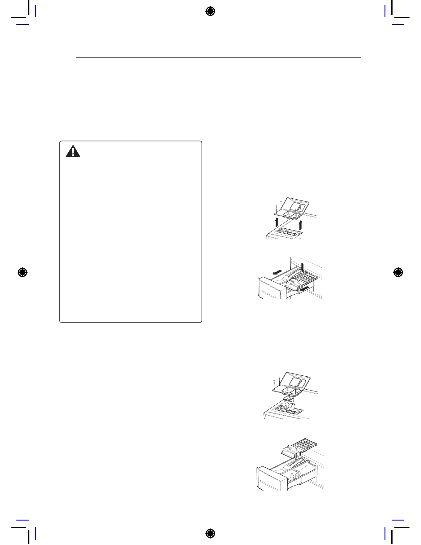
92
MAINTENANCE
MAINTENANCE
Care after wash
After the cycle is finished, wipe the door and the
inside of the door seal to remove any moisture.
Leave the door open to dry the washer tub interior.
Wipe the body of the washing machine with a dry
cloth to remove any moisture
WARNING
• Unplug the washer before cleaning to
avoid the risk of electric shock. Failure to
follow this warning can cause serious injury,
fire, electrical shock, death.
• Never use harsh chemicals, abrasive
cleaners, or solvents to clean the
washer. They will damage the finish.
• Do not use volatile substances (benzene,
paint thinner, alcohol, acetone, etc.)
or detergents with strong chemical
components when cleaning the washing
machine. Doing so may cause discoloration
or damage to the machine, or it may cause
a fire.
• Certain internal parts are intentionally
not grounded and may present a risk of
electric shock only during servicing. Service
personnel - Do not contact the following
parts while the appliance is energized:
pump, valve, motor, control board.
Storing the Washer
If the washer will not be used for an extended
period of time and is in an area that could be
exposed to freezing temperatures:
1
Turn off water supply tap.
2
Disconnect hoses from water supply and drain
water from hoses.
3
Plug the power cord into a properly grounded
electrical outlet.
4
Add 1 gallon of nontoxic recreational vehicle
(RV) antifreeze to the empty wash drum. Close
door.
5
Unplug the power cord, dry the drum interior
with a soft cloth, and close the door.
6
Remove the inserts from the dispenser.
Drain any water in compartments and dry the
compartments.
7
Store the washer in an upright position.
8
To remove the antifreeze from the washer
after storage, run washer through a complete
cycle using detergent. Do not add laundry!
NOTE
• Not all of the RV antifreeze will be expelled.
• Weekly cleaning of the detergent dispenser will
ensure problem free operation.
Cleaning the Dispenser
1
The dispenser should be cleaned periodically
to remove buildup from detergent and other
laundry products.
- Single model -
- Stack model -
2
Remove the inserts from the drawer, and
clean them with warm water and a soft cloth
or brush to remove any residue or buildup.
Wipe out the inside of the drawer opening with
a damp cloth. Reassemble the drawer and
reinstall in the drawer opening.
- Single model -
- Stack model -
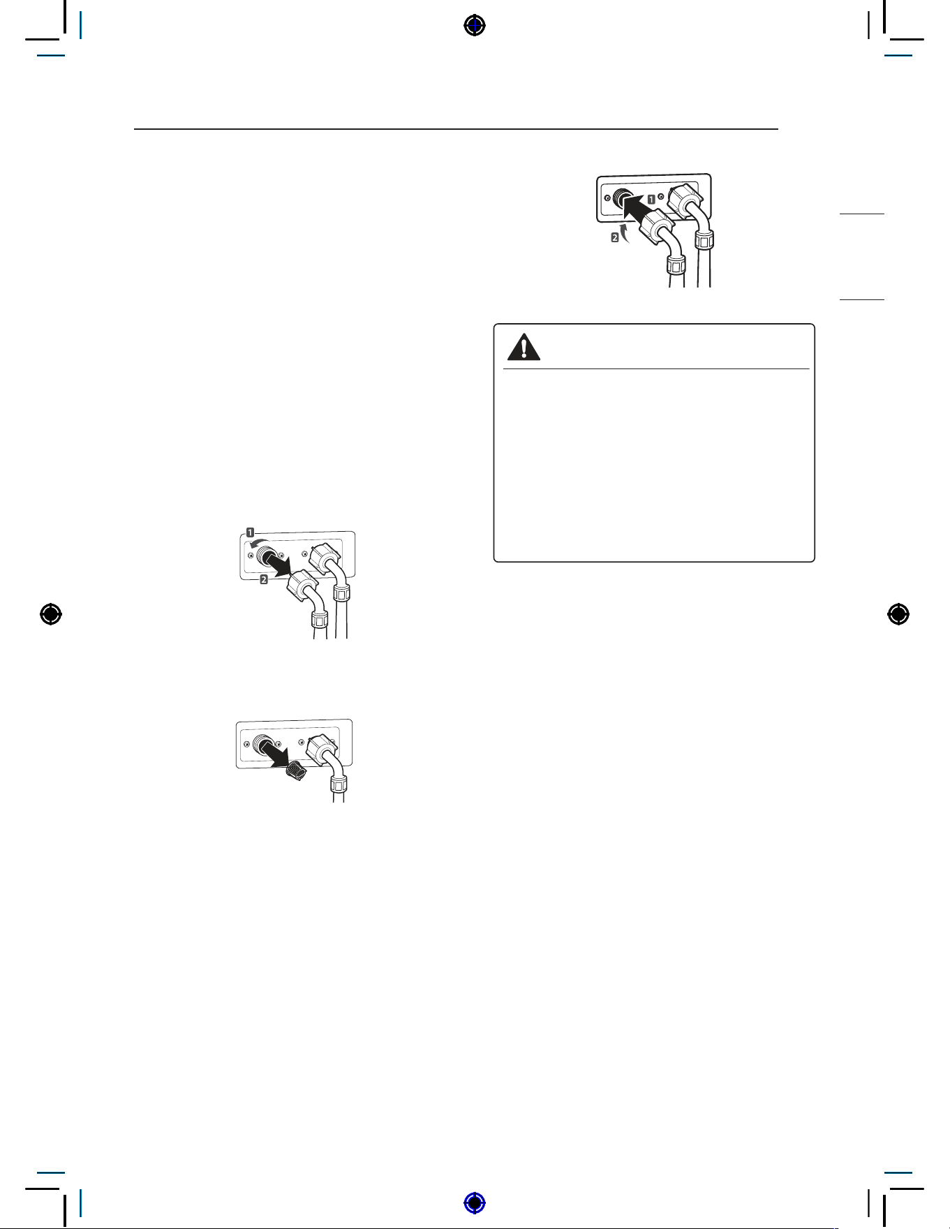
93
MAINTENANCE
HEATER
NOTE
• Do not use anything other than water to clean
the drawer, inserts, and drawer opening.
Cleaning the Water Inlet Filters
Clean the water inlet filters periodically to prevent
clogging. Take extra care to clean the water inlet
filters for areas using hard water. Water may not
be supplied if there are foreign objects, such as
rust, sand, or stones in the water inlet filters.
1
Pull out the plug to turn off the washing
machine.
2
Turn off the faucets connected with the water
inlets.
3
Remove the water inlet hoses.
4
Pull out the water inlet filter.
Inlet Filter
5
Remove foreign objects from the water filter
inlet.
− Soak the water filter inlets in white vinegar
or a lime scale remover or use a toothbrush
to remove foreign objects and rinse
thoroughly.
6
Press the water filter inlets back into place.
7
Reattach the water lines to the washing
machine.
WARNING
• Unplug the power cord and turn off the
faucets before cleaning. Failure to do so
may cause electric shock.
• Do not use the washing machine without
the inlet filters. If you use the washing
machine without the inlet filters it will cause
leaks and malfunction.
• If you use the washing machine in an area
with hard water, the inlet filter may clog due
to lime buildup.
NOTE
• 1\E message will blink on the display when the
water pressure in the detergent drawer is weak
or an inlet filter is clogged with dirt. Clean the
inlet filter.
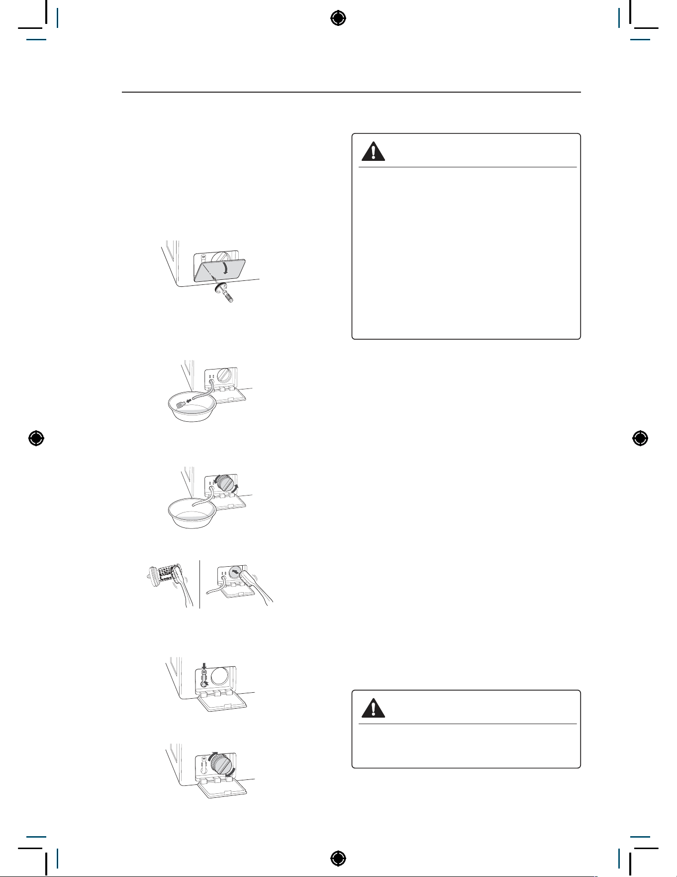
94
MAINTENANCE
Cleaning the Drain Pump Filter
The washing machine fails to drain if the drain
pump filter is clogged. Periodically clean the drain
filter to prevent clogging with foreign objects.
1
Pull out the plug to turn off the washing
machine.
2
Open the drain pump filter cover.
3
Unclip the drain hose and remove the plug
from the drain hose to drain the remaining
water.
4
Twist the pump filter counterclockwise to
remove.
5
Clean the pump filter and opening.
6
Recap the plug onto the drain hose and
reattach the drain hose.
7
Insert the drain pump filter.
8
Close the drain pump filter cover.
WARNING
• Make sure to pull out the plug before
cleaning. Failure to do so may cause
electric shock.
• Opening the drain filter will result in water
overflowing if there is water in the washer
tub. Make sure to check if the water is
completely drained before opening the
drain filter.
• If you use the washing machine with the
drain filter reassembled incorrectly after
cleaning it, or if you use the machine without
the filter, it may cause leaks or malfunction
of the washing machine.
NOTE
• OE message will blink when the drain pump
filter is clogged with dirt. Clean the drain pump
filter.
Cleaning the Door Seal
Clean the door seal once a month to prevent build-
up of dirt in the door seal.
1
Wear rubber gloves and protective goggles.
2
Dilute 3/4 cup (177 ml) of liquid chlorine
bleach in 1 gallon (3.8 L) of water.
3
Soak a sponge or a soft cloth in this diluted
solution and wipe down all around the door
seal.
4
Wipe any moisture with a dry towel or cloth
after cleaning.
5
Leave the door open to allow the door seal to
dry completely.
CAUTION
• Cleaning the door seal with an undiluted
solution may cause malfunction of the door
seal and washing machine parts.

95
MAINTENANCE
HEATER
Cleaning the Drum, Tub Clean
Using the washing machine in a humid space for a
long period of time may lead to a buildup of black
mold and germs in the air inside the washer tub
and affect your health. If you clean the washer tub
regularly on a monthly basis using TUB CLEAN it
will keep the washer tub clean for hygienic use.
1
Add tub cleaner or lime scale remover into the
detergent dispenser drawer.
− Do not exceed the maximum detergent limit
line when you add it. Detergent may remain
in the washer tub after cleaning.
− When you use liquid chlorine bleach, load it
into the liquid chlorine bleach compartment.
When you use a powdered cleaner, add it
into the main wash detergent compartment.
− When you use cleaning tablets, place them
directly into the washer tub. (Do not add
cleaning tablets to the drawer.)
2
Do operate tub clean.
NOTE
• Never load laundry while using TUB CLEAN.
The laundry may damage or become
contaminated. Make sure to clean the washer
tub when it is empty.
• Leave the door open after finishing the laundry
to keep the tub clean.
• TUB CLEAN should be repeated monthly.
• Safely and conveniently secure the door
slightly ajar with a magnetic door plunger. This
will promote air circulation and allow the interior
of the machine to dry.
NOTE
• Wave Force process during the Rinse step helps
in maintaining tub hygiene. The tub is cleaned by
rotating the water-filled tub at an optimized RPM.
• Wave Force is intrinsic within the Rinse step.
No additional setting is required.
• Wave Force is NOT a substitute for the TUB
CLEAN cycle. TUB CLEAN should still be
repeated monthly to maintain hygienic use.
Removing Mineral Buildup
In areas with hard water, mineral scale can form
on internal components of the washer. Periodically
clean the mineral buildup on the internal
components to extend the lifespan of the washer.
Use of a water softener is recommended in areas
with hard water.
• Use a descaler, to remove visible mineral
buildup on the washer tub.
• After descaling, always run the Tub Clean cycle
before washing clothing
• Mineral scale and other spots may be removed
from the stainless steel tub using a soft cloth
soaked in stainless steel cleaner.
• Do not use steel wool or abrasive cleaners.

96
ERROR MODE
ERROR MODE
Meaning of Error Codes that LED displays during occurrence of
problem.
Problem Possible Cause Solution
• Water supply is not adequate in area.
• Water supply taps are not completely open.
• Water inlet hose is bent.
• The filter of the inlet hose clogged.
Check another tap in the house.
Fully open tap.
Straighten hose.
Check the filter of the inlet hose.
• Drain hose is bent or clogged.
• The drain filter is clogged.
Clean and straighten the drain hose.
Clean the drain filter.
• Load is too small.
• Load is out of balance.
• The appliance has an imbalance detection and
correction system. If individual heavy articles
are loaded (bath mat, bath robe, etc.) and the
imbalance is too great, after several attempts to
restart the spin cycle the machine will stop and
the error code will be displayed.
Add 1~2 similar items to help balance
the load.
Rearrange the load in the tub to allow it
to balance properly.
• Is the door opened or not completely closed? Close the door completely.
* If it will not open, call for service.
• Door lock is broken. Check the door switch.
• The water overfills due to a faulty water valve. Close the water tap.
Unplug the power plug.
Call for service.
• The water level sensor malfunction.
• Overload in motor. Restart the cycle after 30 minutes.
If
is not released, call for service.
• Disconnection of card reader cable. Check the card reader wire.
• Too much detergent is used. This is not an error. It indicates a suds
removal routine.
It will clear and restart the cycle when
the suds are gone.
• Thermistor is opened or shorted. Thermistor should be replaced.
• Out of balance sensor is defective. Sensor should be replaced.
• Load is out of balance or the out of balance
sensor is defective.
Rearrange the load in the tub to allow it
to balance properly. If problem persists
replace the sensor.
• Malfunction in Heater system. Check the heater and wire.
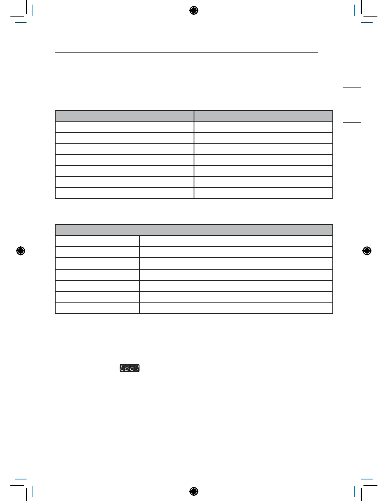
97
POWER FAIL RECOVERY
HEATER
POWER FAIL RECOVERY
In case of power failure, the machine stops running but the time display remains on, showing the time just
before power failure.
DEFAULT WASHER SETTINGS
Default Settings Default
Wash Time 31 Minutes
Rinse Time 17 Minutes
Spin Time 11 Minutes
Rinsing times Twice
Coin #1 Value 0.1
Vend Price 2.00
Top Spin speed 1000 rpm
SPECIFICATIONS
Model
Power supply 220-240 V~ , 50 Hz , 3200-3800 W
Size 700 mm (W) X 770 mm (D) X 983 mm (H), 1396 mm (D with door open)
Weight 87 kg
Wash capacity 10.5 kg Max load(kg) based on IEC load
Sound pressure level Less than 70 dB
Spin speed 1200 rpm max.
Permissible water pressure 1.0-10.0 kgf/cm² (0.1-1.0 MPa)
NOTE
• Specifications subject to change by manufacturer.
• RPM depends on the selected cycle and load type.
• Price setting varies by country.
• Set your country from
• After EEPT, reset your country (Default country is EUK)

98
WIRING DIAGRAM
WIRING DIAGRAM
Single type : CWG27MSOHS/CWG27MSQHS/CWG27MSCHS
SUB PCB
ATOMI
-ZING
BLEACH
MAIN
HOT
MOTOR
COIN DROP SIGNAL
OPTION2
COIN DROP VCC
<NOTE>
THERMISTOR
PRESSURE
SWITCH
DRAIN
PUMP
SOLE
NOID
INLET VALVE
NOISE
FILTER
WASHING HEATER
CARD READER
OPTION1
EXTERNAL FUSE
CIRCULATION
PUMP
AUTO DOSING
SYSTEM
DOOR LOCK SWITCH
VIBRATION
SENSOR
FUSE
DISPLAY PWB
CENTRAL
PAYMENT
CON1
BN
BK
YL
RD
RD
BK
WH
SB
PK
GY
RD
BK
RD
PK
GY
SKY
WH
BK
BK
BN
OR
YL
BL
RD
BK
BK
BK
BK
BK
BK
YL YL
YL
YL
YL
YL
YL
BL
BL
BL
BK
BK
OR
BN
BK
BK
BK
OR OR
SKY
OR
BL BL
BL
WH WH
WH
SKY
SKY
SKY
SKY
RD
RD
RD
RD
RD
GY
SB
WH
WH GY GY
RD
MAIN PWB
RD
BK
YL
BK
BL
WH
WH
WH
BL
WHYL
NA NA
VT
YL
YL
BL
BL
GY
WH
WH
WH WH
WH
BL WH
WH
WHRD
WH
BK
GN/YL
WH
WH
U
V W
SLOT
SLOT
LOCK
SENSOR
BK
BL
BL
NA NA
RD BL BL
BN
NA
P
T
C
P
T
C
NA
NA
NA
#250 TERMINAL
#250 TERMINAL + HOUSING
PIN CONNECTOR
RING TERMINAL GROUND
Base/Line
n n
PWB
RD
RD
REACTOR
BL
BL
WH
WH
SKY
BN
GN/YL
NEUTRAL
EARTH
LIVE
GN/YL
FUSE
FUSE
NA
BL
BL
BL
BL
Wi-Fi
BK
BN
RD
OR
YL
BL
NA
NA
BK
BK
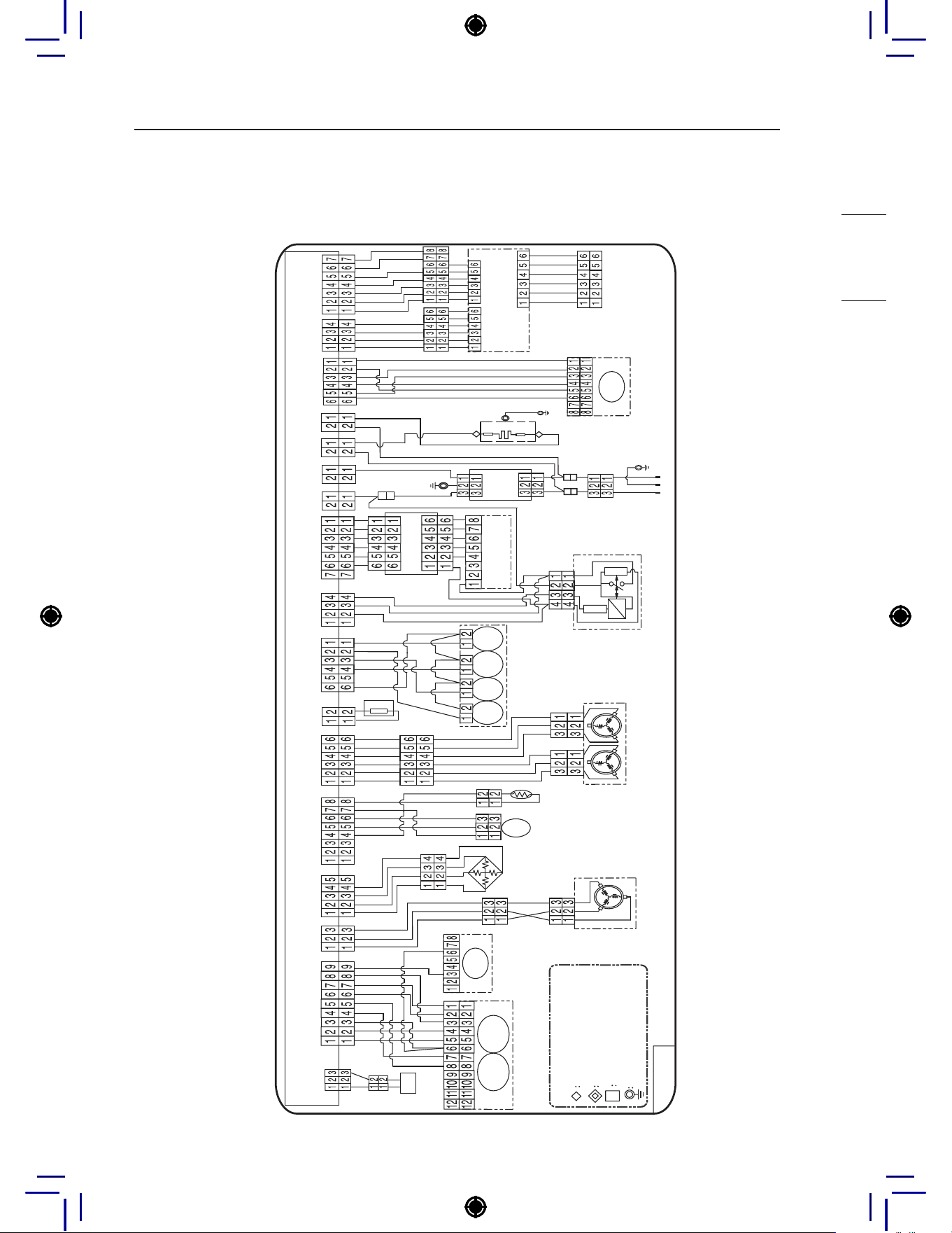
99
WIRING DIAGRAM
HEATER
Stack type : CWG27MDOHS/CWG27MDQHS/CWG27MDCHS
SUB PCB
BLEACH
ATOMI
-ZING
SOFTE
-NER
MAIN
HOT
MOTOR
COIN DROP SIGNAL
OPTION2
COIN DROP VCC
<NOTE>
THERMISTOR
PRESSURE
SWITCH
DRAIN
PUMP
SOLE
NOID
INLET VALVE
NOISE
FILTER
WASHING HEATER
CARD READER
OPTION1
EXTERNAL FUSE
CIRCULATION
PUMP
AUTO DOSING
SYSTEM
DOOR LOCK SWITCH
VIBRATION
SENSOR
FUSE
DISPLAY PWB
CENTRAL
PAYMENT
CON1
BN
BK
YL
RD
RD
BK
WH
SB
PK
GY
RD
BK
RD
PK
GY
SKY
WH
BK
BK
BN
OR
YL
BL
RD
BK
BK
BK
BK
BK
BK
YL YL
YL
YL
YL
YL
YL
BL
BL
BL
BK
BK
OR
BN
BK
BK
BK
OR OR
SKY
OR
BL BL
BL
WH WH
WH
SKY
SKY
SKY
SKY
RD
RD
RD
RD
RD
GY
SB
WH
WH GY GY
RD
MAIN PWB
RD
BK
YL
BK
BL
WH
WH
WH
BL
WHYL
NA NA
VT
YL
YL
BL
BL
GY
WH
WH
WH WH
WH
BL WH
WH
WHRD
WH
BK
GN/YL
WH
WH
U
V W
SLOT
SLOT
LOCK
SENSOR
BK
BL
BL
NA NA
RD BL BL
BN
NA
P
T
C
P
T
C
NA
NA
NA
#250 TERMINAL
#250 TERMINAL + HOUSING
PIN CONNECTOR
RING TERMINAL GROUND
Base/Line
n n
PWB
RD
RD
REACTOR
BL
BL
WH
WH
SKY
BN
GN/YL
NEUTRAL
EARTH
LIVE
GN/YL
FUSE
FUSE
NA
BL
BL
BL
BL
Wi-Fi
BK
BN
RD
OR
YL
BL
NA
NA
BK
BK

Memo

PARTS AND ACCESSORIES .........................................................3
Parts ..................................................................................................................3
Accessories .......................................................................................................3
CONTROL PANEL FEATURES ......................................................4
Coin type ...........................................................................................................4
OPL type ...........................................................................................................4
Card type...........................................................................................................5
INSTALLATION INSTRUCTIONS ...................................................7
Checking and choosing the proper location ......................................................7
Unpacking and removing shipping bolts ...........................................................8
Connecting the water lines ................................................................................9
Connecting the drain line ................................................................................10
Leveling the washing machine ........................................................................11
PREPARATION .............................................................................12
Precautions for fabric care before wash cycle ................................................12
Fabric care labels ............................................................................................13
Sorting laundry ................................................................................................13
How to wash better .........................................................................................13
Laundry loading guide .....................................................................................14
About the dispenser ........................................................................................14
Loading the dispenser .....................................................................................15
OPERATING YOUR WASHER .....................................................16
PROGRAMMING MODE ...............................................................17
Structure of Programming mode – Card / Coin type .......................................18
Structure of Programming mode – OPL type ..................................................19
PROGRAMING MODE – SETUP MODE ......................................20
Setup Mode :
(display) .......................................................................20
PROGRAMING MODE – TEST MODE .........................................74
Diagnostic tests: (display) .....................................................................74
PROGRAMING MODE – COLLECT MODE .................................82
Collect information data :
(display) .....................................................82
Collect Mode Data lists ...................................................................................82
This manual may contain images or content
different from the model you purchased.
This manual is subject to revision by the
manufacturer.

TABLE OF CONTENTS
SMART FUNCTIONS ....................................................................84
Open Source Software Notice Information......................................................84
MAINTENANCE ............................................................................85
Care after wash ...............................................................................................85
ERROR MODE ..............................................................................89
POWER FAIL RECOVERY ...........................................................90
DEFAULT WASHER SETTINGS ..................................................90
SPECIFICATIONS .........................................................................90
WIRING DIAGRAM .......................................................................91

3
PARTS AND ACCESSORIES
NON HEATER
PARTS AND ACCESSORIES
Parts
Detergent
dispenser
(for single
model)
Detergent dispenser
drawer (for stack
model)
Control
panel
Power cord
Drain hose
Door seal
Tub
Leveling feet
Drain pump filter cover
Drain pump filter
Drain hose
Door Magnet
Door Plunger
(see page 2)
Water
inlets
Shipping
bolts
Accessories
Hot and Cold Water
Hoses
Non-skid pads
Caps (4) (for covering
shipping bolt holes)
Wrench (for removing
shipping bolts and
adjusting leveling feet)
Hole cap (5) (for
securing auto dosing
hole)
Tie Strap (for securing
drain hose)
Elbow Bracket (for
securing drain hose)
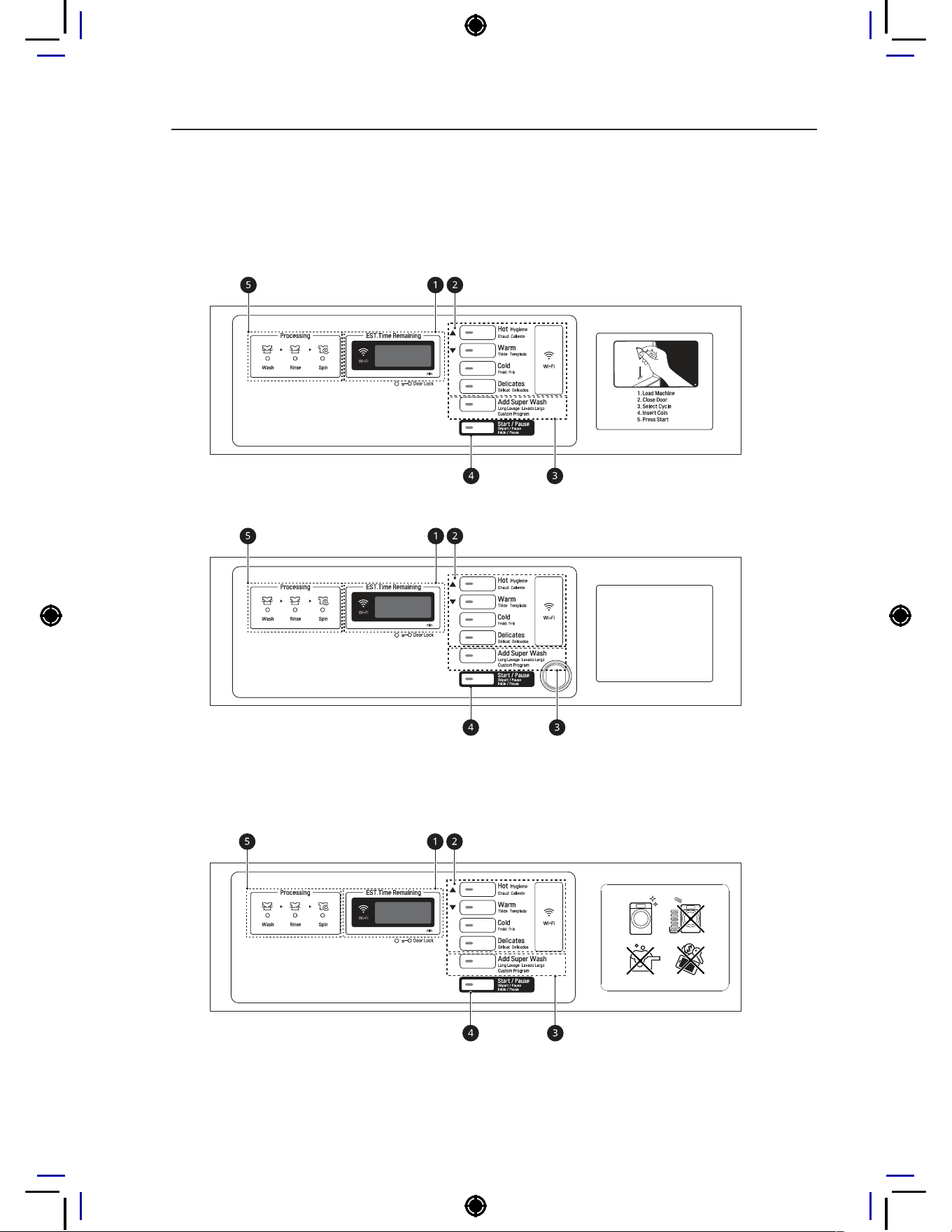
4
CONTROL PANEL FEATURES
CONTROL PANEL FEATURES
Coin type
- Side by side
- Stack
OPL type
- Side by side
- Stack
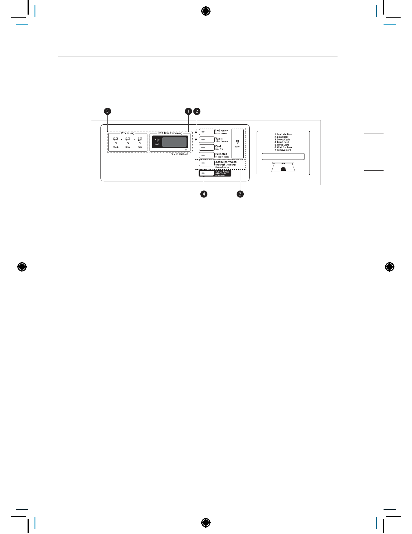
5
CONTROL PANEL FEATURES
NON HEATER
Card type
- Side by side
- Stack
a
Display LED
b
Cycle button
c
Optional function button
d
Start/Pause button
e
Status LED
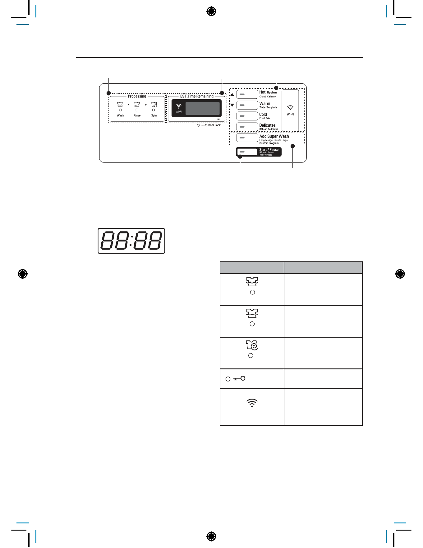
6
CONTROL PANEL FEATURES
Cycle button
Start/Pause button Optional function button
Display LEDStatus LED
Display LED
The display shows the vend price and remaining
time and programming options. Error codes are
also displayed here.
Cycle Buttons
Press the CYCLE buttons to select the desired
cycle based on laundry types and conditions.
Hot
Use this cycle for heavily soiled loads.
Hygiene
Use this cycle to reduce laundry bacteria by using
heater.
Warm
Use this cycle for loads with moderately heavy soil.
Cold
Use this cycle for loads with normal soil.
Delicates
Use this cycle to wash sensitive fabrics that can be
easily damaged.
Optional function button
Add Super Wash: Wash time or rinse cycle can
be added when additional coin is inserted or a
valid cash card is entered.
Custom Program: Customized cycle program can
be used. Only available in OPL type.
Start/Pause button
The Start/Pause LED flashes when the full vend
price has been satisfied and the cycle has been
chosen.
Status LED
LED Description
Wash
LED flashes whenever
the Washing cycle is in
operation.
Rinse
LED flashes whenever
the Rinsing cycle is in
operation.
Spin
LED flashes whenever
the Spinning cycle is in
operation.
Door Lock
LED flashes whenever
the door lock is activated.
Wi-Fi
LED flashes when the
Wi-Fi is connecting.
LED stays lit when the
Wi-Fi is connected.
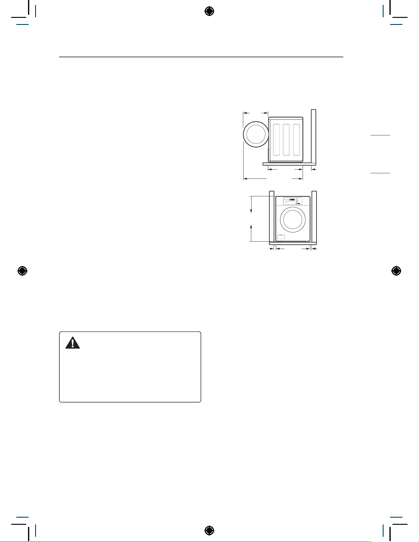
7
INSTALLATION INSTRUCTIONS
NON HEATER
INSTALLATION INSTRUCTIONS
Checking and choosing
the proper location
Install the washing machine on a solid concrete
cement that is strong and rigid enough to support
the weight of the washing machine, even when
fully loaded, without flexing or bouncing. If the floor
has too much flex, you may need to reinforce it to
make it more rigid. If the floor is not solid, it may
cause severe vibration and noise.
1
Clean the floor before installation.
− Make sure to select solid and smooth
ground.
2
Two or more people are needed for moving
and unpacking the washing machine.
3
Allow for sufficient space between the walls
and the washing machine for installation.
Space requirements
You must allow sufficient space for water lines, the
drain line, and airflow.
NOTE
• Be sure to allow for wall, door, or floor moldings
that may increase the required clearances.
WARNING
• Certain internal parts are intentionally
not grounded and may present a risk of
electric shock only during servicing. Service
personnel - Do not contact the following
parts while the appliance is energized:
pump, valve, motor, control board.
Installing on a floor
77 cm
10 cm
139.6 cm
62.6 cm
98.3 cm
2.5 cm 2.5 cm
70 cm
NOTE
• The floor must be strong and rigid enough to
support the weight of the washer, when fully
loaded, without flexing or bouncing. If your floor
has too much flex, you may need to reinforce
it to make it more rigid. A floor that is adequate
for a top-loading washer may not be rigid
enough for a front loading washer, due to the
difference in the spin speed and direction. If the
floor is not solid, your washer may vibrate and
you may hear and feel the vibration throughout
your house.
• Before installing the washer, make sure the
floor is clean, dry and free of dust, dirt, water
and oils so the washer feet can not slide easily.
Leveling feet that can move or slide on the floor
can contribute to excess vibration and noise
due to poor contact with the floor.
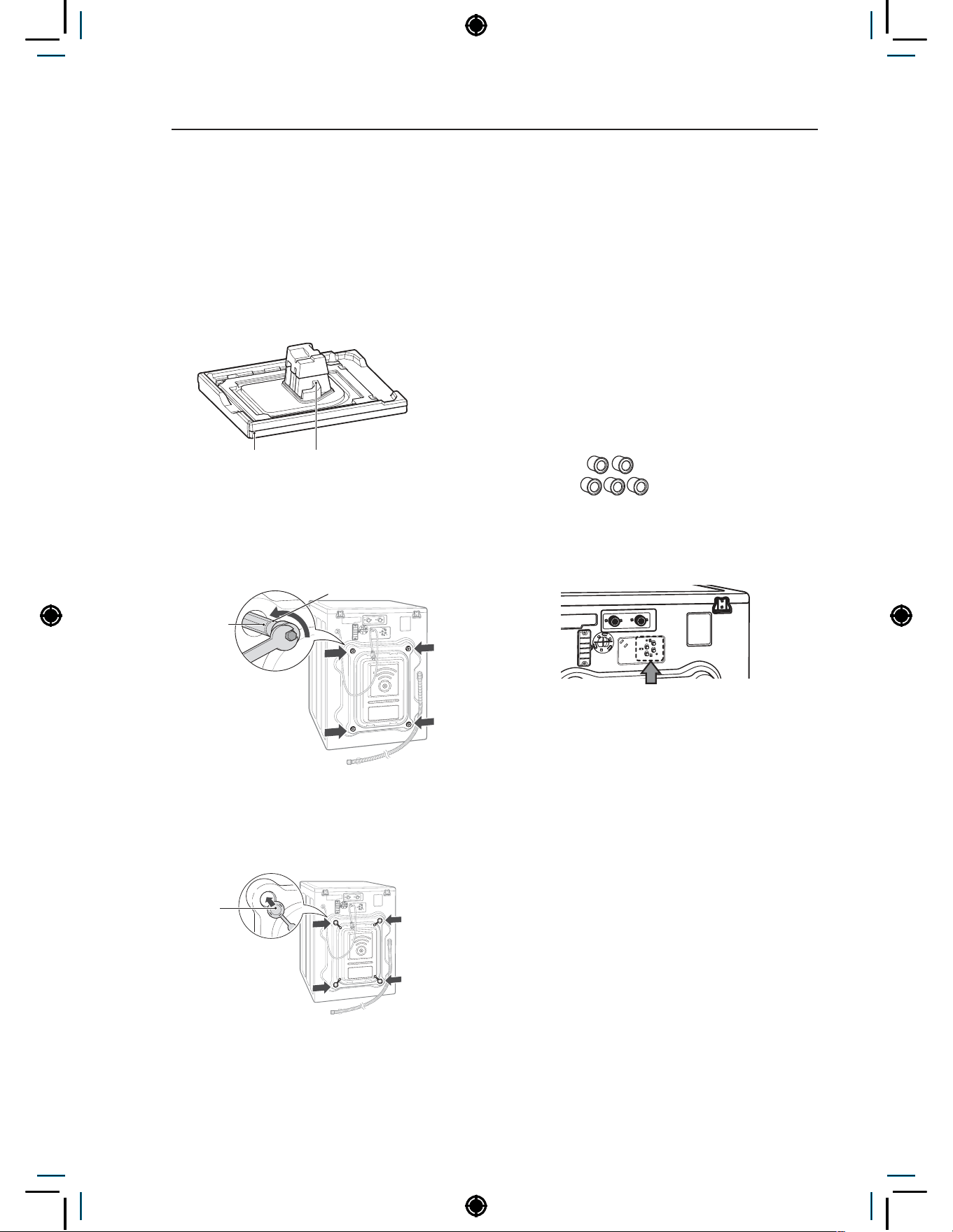
8
INSTALLATION INSTRUCTIONS
Unpacking and removing
shipping bolts
When removing the washer from the carton
base, be sure to remove the foam drum support
in the middle of the carton base. If you must lay
the washer down to remove the base packaging
materials, always lay it carefully on its side.
DO NOT lay the washer on its front or back.
Carton Base Foam Tub Support
1
Remove the bottom two shipping bolts
with the wrench (included) to fully loosen
all four shipping bolts by turning them
counterclockwise and then pulling them out.
Shipping
bolt
Retainer
2
Locate the four hole caps included in the
accessory pack and install them in the
shipping bolt holes.
Cap
NOTE
• Save the bolt assemblies for future use. To
prevent damage to internal components, DO
NOT transport the washer without reinstalling
the shipping bolts.
• Failure to remove shipping bolts and retainers
may cause severe vibration and noise, which
can lead to permanent damage to the washer.
The cord is secured to the back of the washer
with a shipping bolt to help prevent operation
with shipping bolts in place.
Installing Hole cap
1
Take the hole cap out from manual bag.
Hole cap
2
Insert the hole cap (4 pieces) into hose
connect in back of the machine.
NOTE
• In case of using auto dosing feature, inserting
hole cap is unnecessary.
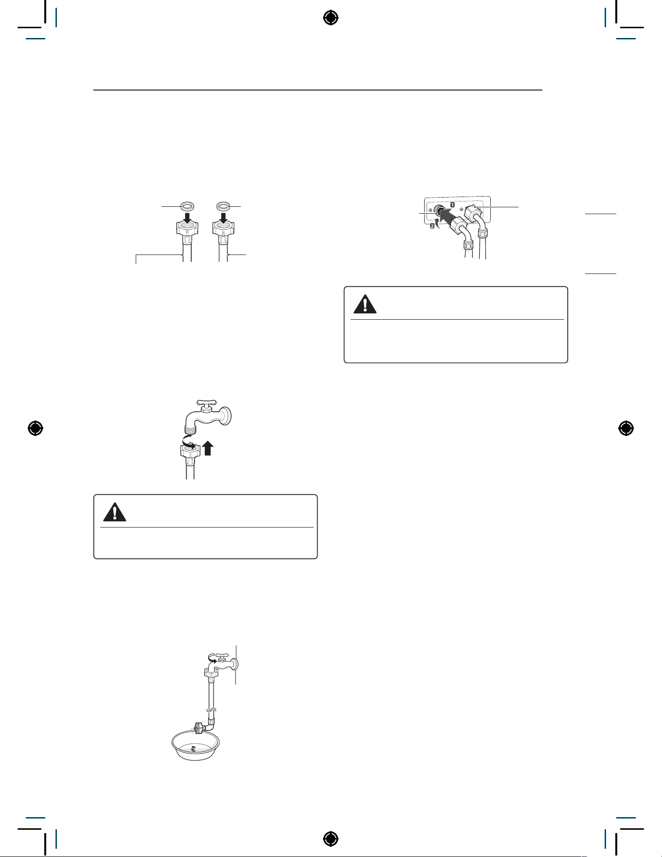
9
INSTALLATION INSTRUCTIONS
NON HEATER
Connecting the water lines
1
Check the rubber seals on both sides of the
hose.
− Insert a rubber seal into the threaded fittings
on each hose to prevent leaking.
2
Connect the water supply hoses to the HOT
and COLD water faucets tightly by hand and
then tighten another 2/3 turn with pliers.
− Connect the blue hose to a cold water
faucet and the red hose to a hot water
faucet.
WARNING
• Do not overtighten. Damage to the
coupling can result.
3
After connecting inlet hose to water faucets,
turn on the water faucets to flush out foreign
substances (dirt, sand, sawdust) in the water
lines. Let water drain into a bucket, and check
the water temperature.
4
Connect the hoses to the water inlets tightly
by hand and then tighten another 2/3 turn with
pliers.
− Connect the blue hose to the cold water
inlet and the red hose to the hot water inlet.
WARNING
• Do not overtighten the hoses.
Overtightening can damage the valves
resulting in leaking and property damage.
5
Check for leaks by turning on the faucets.
− If water leaks, check steps 1 to 4 again.
NOTE
• For your safety, and for extended product
life, use only authorized components. The
manufacturer is not responsible for product
malfunction or accidents caused by the use of
separately purchased unauthorized parts.
• Use new hoses when you install the washing
machine. Do not reuse old hoses. Use only the
inlet hoses provided with the washer. LG does
not recommend the use of aftermarket hoses.
• Periodically check the hoses for cracks, leaks
and wear, and replace the hoses every 5 years.
• Do not stretch the water hoses intentionally,
and make sure that they are not crushed by
other objects.
• Water supply pressure must be between 1.0
kgf/cm² and 10.0 kgf/cm² (100~1000 KPa). If
the water supply pressure is more than 10.0
kgf/cm², a pressure reducing valve must be
installed.
• To provide optimum washing performance the
hot water temperature should be set at 120-
135°F (48-57°C) and the cold at 60°F (15°C).
Rubber seal
Rubber seal
Water hose
(To faucet)
Water hose (To water
inlet on the washing
machine)
Cold
water
inlet
Hot water
inlet
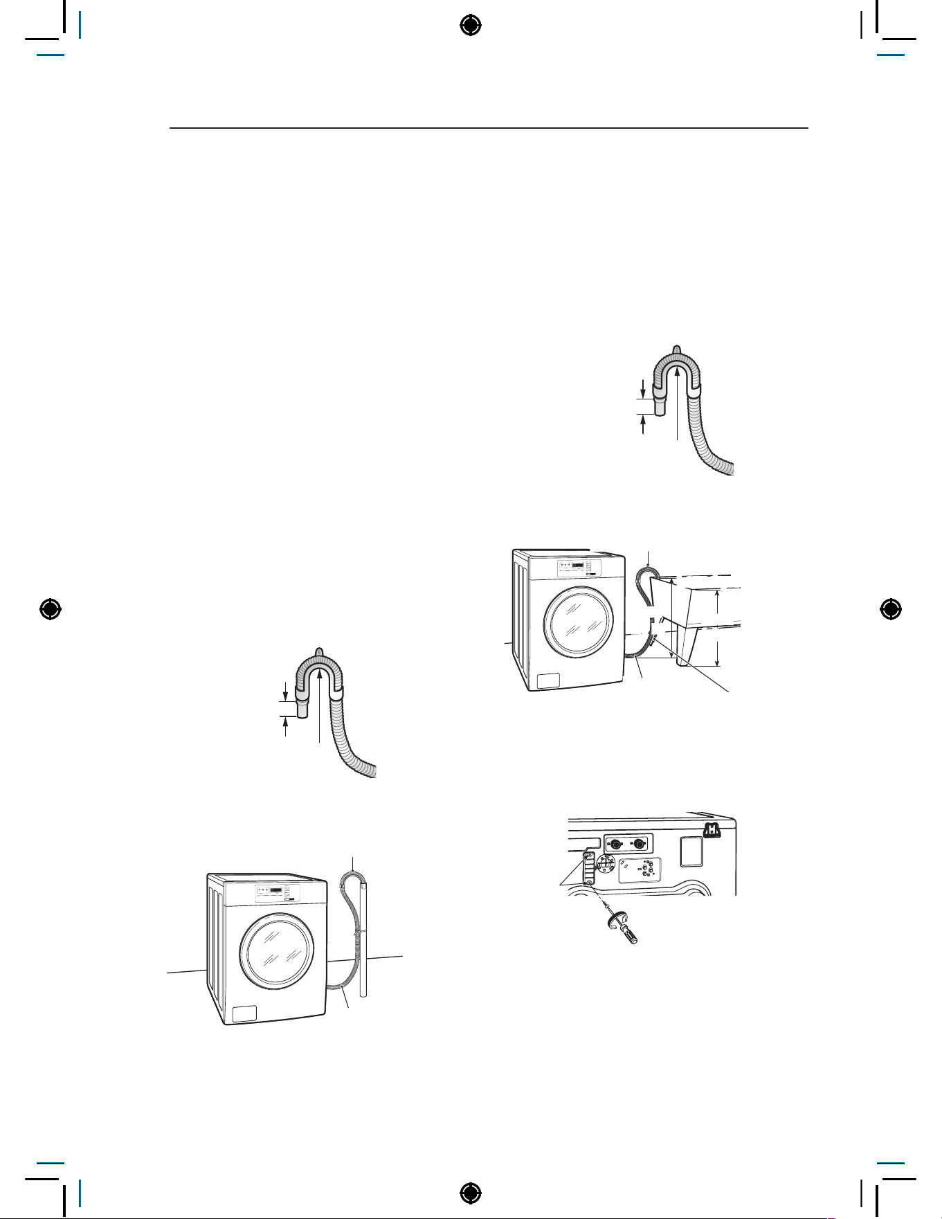
10
INSTALLATION INSTRUCTIONS
Connecting the drain line
Secure the drain hose in place to prevent moving
and leaking.
NOTE
• The drain hose should be properly secured.
Failure to properly secure the drain hose can
result in flooding and malfunction.
• Total height of the hose end should not exceed
100.0 cm from the bottom of the washer.
• The drain must be installed in accordance with
any applicable local codes and regulations.
• Make sure that the water lines are not
stretched, pinched, crushed, or kinked.
Using a standpipe
1
Clip the end of the hose into the elbow
bracket.
− Connect the elbow bracket within 10 cm
from the end of the drain hose. If the drain
hose is extended more than 10 cm beyond
the end of the elbow bracket, mold or
microorganisms could spread to the inside
of the washer.
No more
than 10 cm
Elbow Bracket
2
Insert the end of the drain hose into the
standpipe.
Elbow Bracket
Drain Hose
3
Use a tie strap to secure the drain hose in
place.
Using a laundry tub
1
Clip the end of the hose into the elbow
bracket.
− Connect the elbow bracket within 10 cm
from the end of the drain hose. If the drain
hose is extended more than 10 cm beyond
the end of the elbow bracket, mold, or
microorganisms could spread to the inside
of the washer.
No more
than 10 cm
Elbow Bracket
2
Hang the end of the drain hose over the side
of the laundry tub.
Elbow Bracket
max.
1.0 m
max.
1.0 m
Laundry Tub
Drain Hose
Tie Strap
3
Use a tie strap to secure the drain hose in
place.
Connecting the auto dosing
1
Unscrew the 2 screws on the protective cover
and remove the cover.
2
Connect the auto dosing harness from
Accessory parts.
NOTE
• The voltage of the auto dosing machine should
be the same as the washer’s voltage.
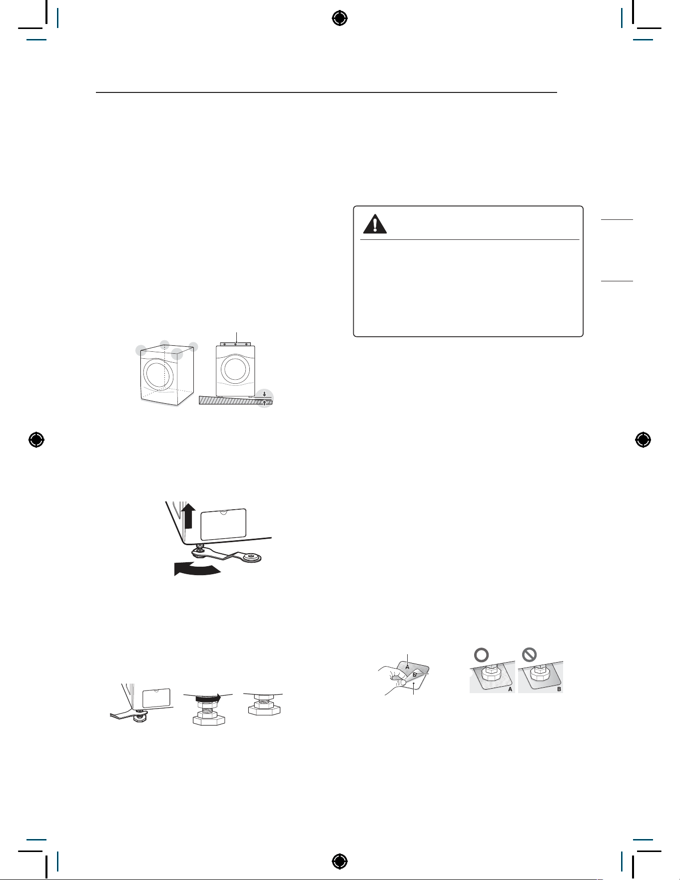
11
INSTALLATION INSTRUCTIONS
NON HEATER
Leveling the washing
machine
The washer tub of your new washing machine
spins at very high speeds. To minimize vibration,
noise, and unwanted movement, the floor must be
perfectly level and solid.
1
Check the washing machine’s level.
− Check the precise level by rocking the top
edges of the washing machine or placing
a level on the washing machine. The slope
beneath the washing machine must not
exceed 1°, and all four leveling feet must
rest firmly on the floor.
1°
Level
2
Turn the lower leveling feet clockwise to level
the washing machine.
− Turning the lower leveling feet clockwise
raises the washing machine.
Raise
3
Turn the locknuts counterclockwise and
tighten them when the washing machine is
level.
Tighten all 4 lock
nuts securely using
the wrench.
4
Check the washing machine’s level again.
− Push or rock the top edges of the washing
machine gently to make sure that the
washing machine does not rock.
− If the washing machine rocks, repeat steps
1 to 3.
WARNING
• Using the washing machine without leveling,
it may result in malfunction caused by the
production of excess vibration and noise.
• Use the leveling feet only when you level
the washing machine. If you raise the
leveling feet unnecessarily, it may cause
abnormal ibration of the washing machine.
Using non-skid pads (optional)
If you install the washing machine on a slippery
surface, it may move because of excessive
vibration. Incorrect leveling may cause malfunction
through noise and vibration. In the event of this,
lay the non-skid pads under the leveling feet and
adjust the level.
1
Clean the floor to attach the non-skid pads.
− Use a dry rag to remove and clean foreign
objects or moisture. If moisture remains, the
non-skid pads may slip.
2
Adjust the level after placing the washing
machine in the installation area.
3
Place the adhesive side of the non-skid pad
on the floor.
− It is most effective to install the non-skid
pads under the front legs. If it is hard to
place the pads under the front legs, place
them under the back legs.
This side up
Remove
backing
Adhesive
side
4
Check the washing machine’s level again.
− Push or rock the top edges of the washing
machine gently to make sure that the
washing machine does not rock. If the
washing machine rocks, level the washing
machine again.

12
PREPARATION
• Check all pockets to make sure that they are
empty.
− Items such as clips, matches, pens, coins,
and keys can damage both your washer and
your clothes.
• Close zippers, hooks, and drawstrings to
prevent these items from snagging or tangling
on other clothes.
• Pretreat heavily stained areas before washing.
− Doing so will produce clean, stain-free
results.
• Combine large and small items in a load. Load
large items first.
• The washer can be fully loaded, but the drum
should not be tightly packed with items.
− The door of the washer should close easily.
• Do not wash waterproof clothes.
− This may cause abnormal vibration or may
cause the load to bounce, which could
damage the tub.
• Check if there are any other foreign objects in
the door seal and take extra care that clothes
do not get caught there.
− Foreign objects in the door seal may stain
clothes, and water may leak if clothes get
caught in the door seal.
• Wash underwear or small, light items in a
laundry net.
− Small, light items may get caught in the door
seal, and a brassiere hook may damage
other items or the tub.
• Brush heavy soil, dust, or hair off fabrics before
washing.
− Laundry may not wash clean if there is dirt or
sand on the fabrics, or they may be damaged
due to particles rubbing against sheer fabrics.
• Wash blankets individually.
− Washing more than one blanket together
may produce unclean results due to tangling
or an unbalanced load.
• Always separate fabrics according to their
colors and wash them separately to prevent
colors from running.
− Fabrics may damage or become stained
due to fabric dyes running or due to foreign
objects transferring from one fabric to
another.
PREPARATION
Precautions for fabric care before wash cycle
Read and observe the following to prevent shrinkage or damage to clothes.

13
PREPARATION
NON HEATER
Fabric care labels
Most articles of clothing feature fabric care labels
that include instructions for proper care.
Category Label Directions
Washing
Hand Wash
Machine Wash, Normal
Cycle
Use Permanent Press/
Wrinkle Resistant
washing machine
setting (which has
a cool down or cold
spray before the
reduced spin)
Use Gentle/Delicate
washing machine
setting (slow agitation
and/ or reduced wash
time).
Do Not Wash
Do Not Wring
Water
Temperature
Hot
Warm
Cold/Cool
Bleach
symbols
Any Bleach (When
Needed)
Only Non-Chlorine
Bleach (When Needed)
Do Not Bleach
Sorting laundry
It is recommended that you sort laundry into
similar loads that are washable in the same cycle.
Refer to the following chart for sorting clothes
Colors Whites / Lights / Darks
Soil Heavy / Normal / Light
Fabric
Delicates / Easy Care / Sturdy
Cottons
Lint Lint Producers / Lint Collectors
How to wash better
It is recommended to follow the below guide for
better wash performance.
Load Type
Recommended
Capacity
How to Wash
Better
Everyday
Clothes
Less Than
10kg
Frontload
washers use
dropping
action for wash
performance.
Therefore,
it is better
to NOT fully
load the drum.
Oversudsing
also prevents
efficient wash
performance.
Blanket Less Than 7kg
Do not use 2
blankets with
big differences
in size.
It may not
extract properly.
Use similar-
sized blankets.
Bed Sheets Less Than 7kg
Any Bleach
(When Needed)
Carpet/Rug Do Not Use
Only Non-
Chlorine Bleach
(When Needed)
Footwear Do Not Use Do Not Bleach
Pillow Do Not Use
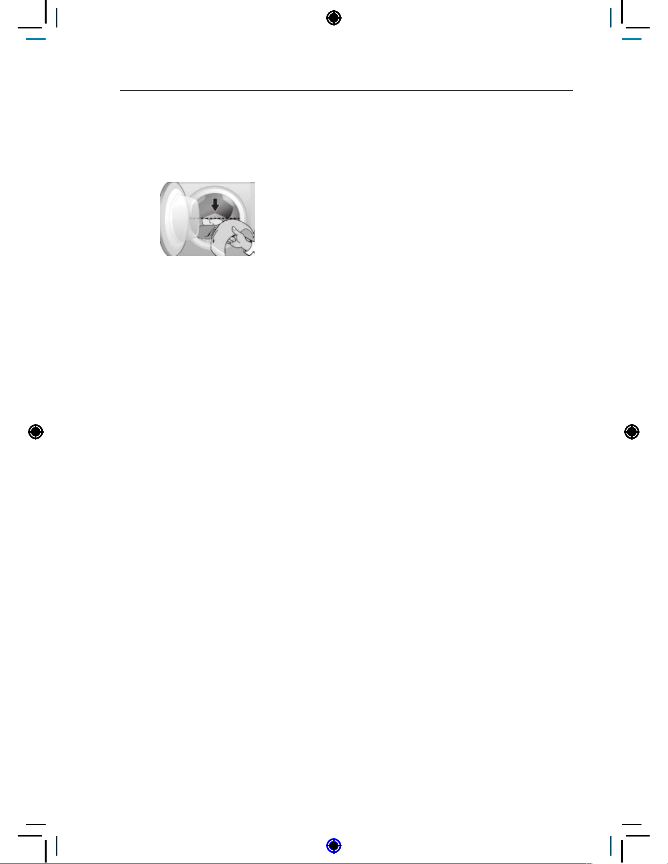
14
PREPARATION
Laundry loading guide
Loading your laundry following the below guide
will help to increase the lifetime and wash
performance of the washer
• Single items or mixed items that include large
items should be less than half of the maximum
capacity(dry condition).
− Single items : Consists only of one type of
garment, such as 5kg of towel.
− Mixed items : Consists of various types of
garments.
− Large item : bed linen/sheet, bath sheet, bath
towel, and blanket.
• Mixed items (without large items) should
only be loaded up to 2/3 of the drum for
optimal performance.
NOTE
• Do not overload as this reduces cleaning
efficiency and causes gasket wear.
About the dispenser
The automatic dispenser consists of three
compartments which hold:
• Liquid chlorine bleach.
• Liquid fabric softener.
• Liquid and powdered detergent and colorsafe
bleach for main wash.
All laundry products can be added at once in their
respective dispenser compartments. They will be
dispensed at the appropriate time for the most
effective cleaning.
After adding the laundry products to the dispenser,
close the dispenser cover.
To add detergent, bleach, and fabric softener to
the automatic dispenser:
1
Open the dispenser cover.
2
Load the laundry products into the appropriate
compartments.
3
Slowly close the dispenser cover to avoid
early dispensing of the laundry products.
NOTE
• It is normal for a small amount of water to
remain in the dispenser compartments at the
end of the cycle.
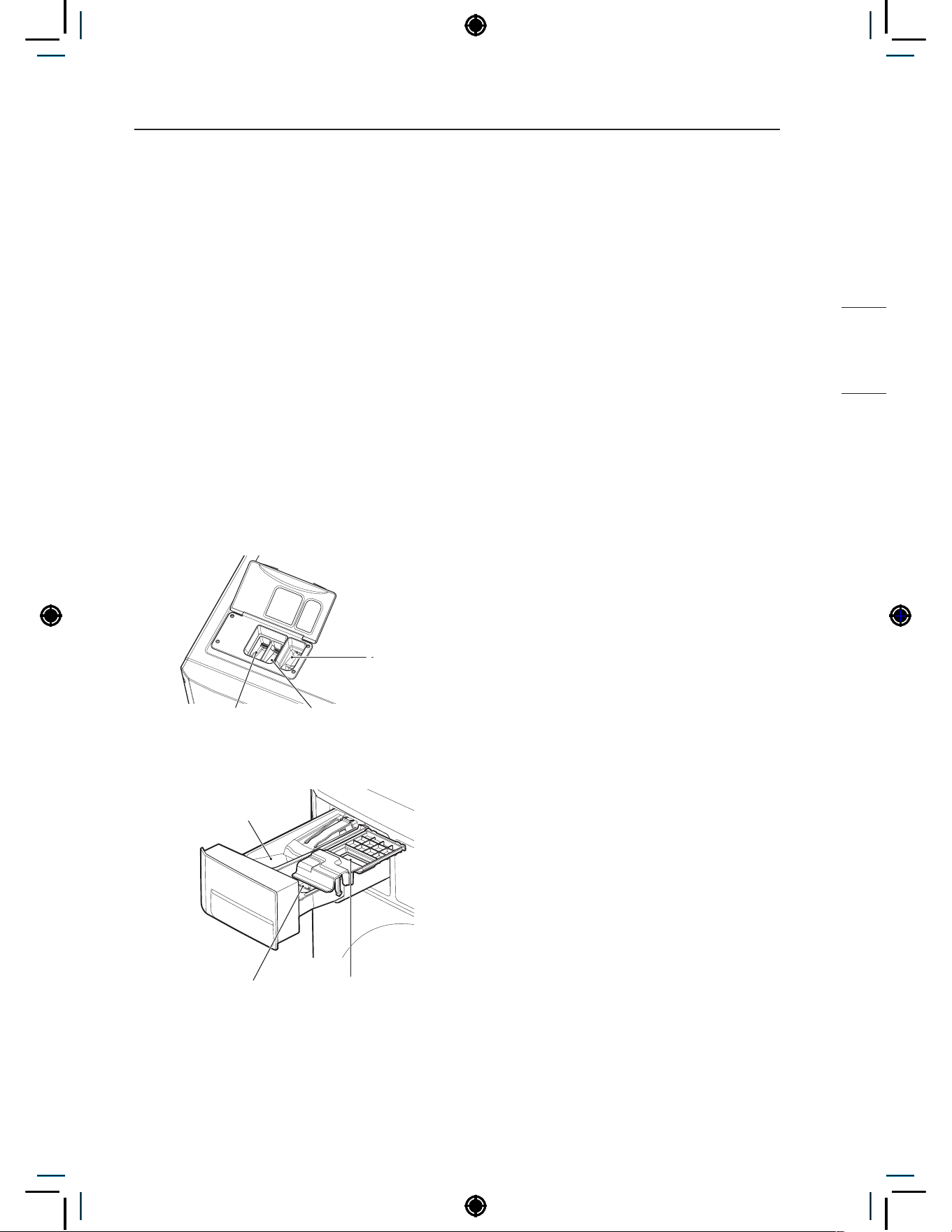
15
PREPARATION
NON HEATER
Loading the dispenser
Main Wash Detergent Compartment
This compartment holds laundry detergent for the
main wash cycle, which is added to the load at the
beginning of the cycle.
Follow the detergent manufacturer’s instructions
with respect to the amount of detergent to use, and
never use more than the recommended amount.
Using too much detergent can result in detergent
buildup in clothing and the washer. Either
powdered or liquid detergent may be used.
NOTE
• Liquid or powdered color-safe bleach may be
added to the main wash compartment with
detergent of the same type.
- Single model -
Liquid Fabric Softener
Compartment
Liquid Chlorine
Bleach Compartment
Main Wash
Detergent
Compartment
- Stack model -
Liquid Fabric Softener
Compartment
Liquid Chlorine
Bleach Compartment
Main Wash Detergent
Compartment
Liquid Bleach Compartment
This compartment holds liquid chlorine bleach,
which will be dispensed automatically at the proper
time during the wash cycle.
NOTE
• Do not add powdered or liquid color-safe
bleach to this compartment.
• Always follow the manufacturer’s
recommendations when adding bleach. Do not
exceed the maximum fill line. Using too much
bleach can damage fabrics.
• Never pour undiluted liquid chlorine bleach
directly onto the load or into the drum. Fabric
damage can occur.
Fabric Softener Compartment
This compartment holds liquid fabric softener,
which will be automatically dispensed during the
final rinse cycle.
NOTE
• Always follow the manufacturer’s
recommendations when adding fabric softener.
Do not exceed the maximum fill line. Using
too much fabric softener may result in stained
clothes.
• Dilute concentrated fabric softeners with warm
water. Do not exceed the maximum fill line.
• Never pour fabric softener directly onto the load
or into the drum.
• Do not add the fabric softener sheets to this
compartment.
• Do not add ‘fabric sheet softener’ into the
dispenser draw as it is likely to cause water
to leak out. If ‘fabric sheet softener’ has been
added, please pull out the dispenser draw and
remove.
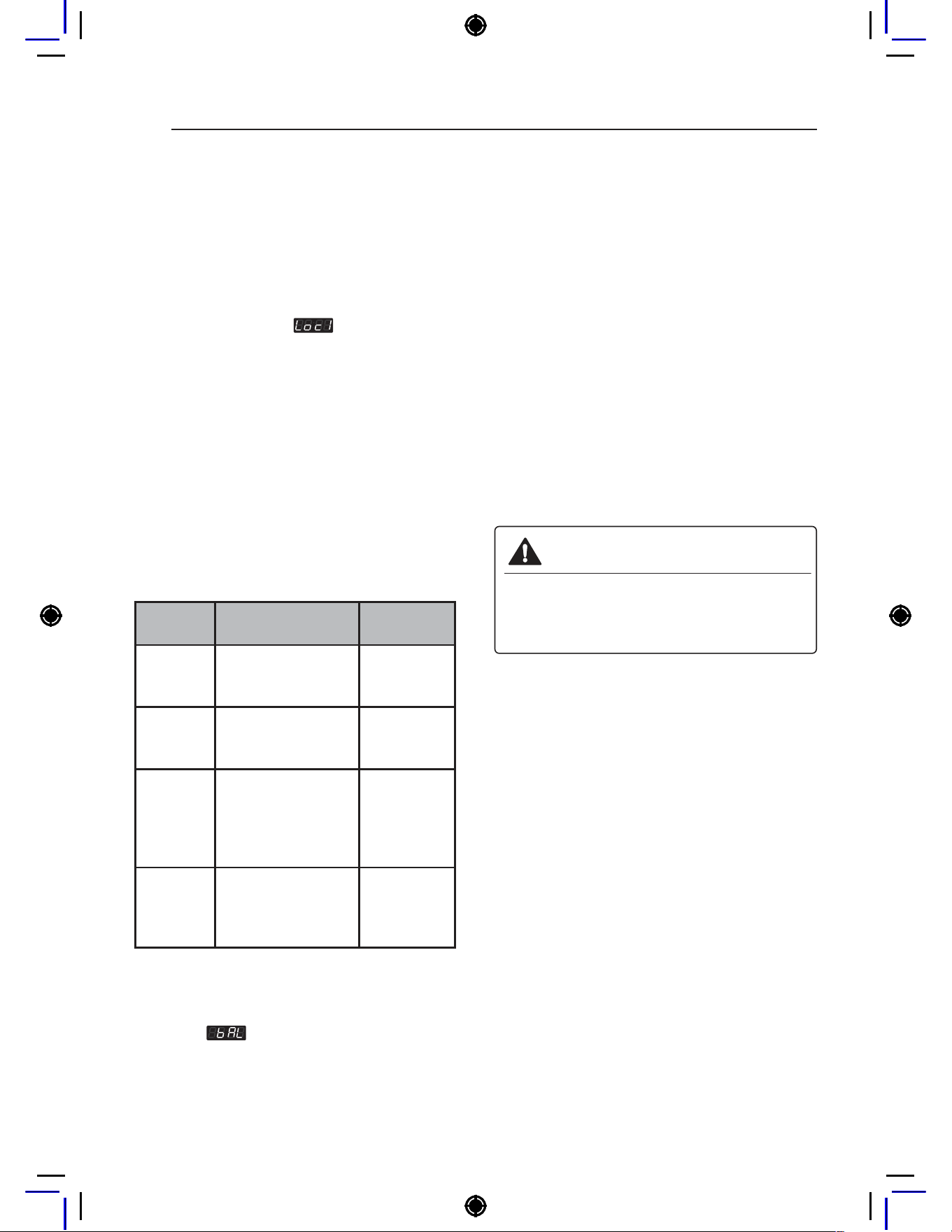
16
OPERATING YOUR WASHER
1
Ready mode
− All types of machines show ‘PUSH’
NOTE
• Price setting varies by country
• Set your country from
mode
• After EEPT, reset your country (Default country
is EUK)
2
Select the cycle
Press the desired button and the display will show
you the price of the cycle.(You cannot change the
cycle while the machine is running.)
• Add Super Wash (Optional, only in Coin/Card
type)Wash time or rinse cycle can be added
when additional coin is inserted, or a valid cash
card is entered.
• Select cycles designed for different types
of fabric and soil levels.
CYCLE Fabric type
Wash/Rinse
Temp.
Hot,
Hygiene
Cotton, linen,
towels, shirts,
sheets
Hot / Cold
Warm
Cotton, mixed
loads, work clothes,
jeans, shirts
Warm / Cold
Cold
Cotton, dress shirts,
pants, wrinkle-free
clothing, cotton/
poly blend clothing,
tablecloths
Cold / Cold
Delicates
Dress shirts,
blouses, nylons,
sheer or lacey
garments
Cold / Cold
NOTE
• When the card balance is insufficient, machine
displays
and the card balance.
3
Insert Coin/Card (Not for OPL type)
Insert a sufficient amount of change that is more
than the programmed vend price for the selected
cycle.Insert a card that has a sufficient balance.
The card balance should be more than the
programmed vend price for the selected cycle.
4
Change cycle
You can not change the cycle while the machine
is running.
5
Cycle finish
The machine stops and the display shows ‘End’
with beep sound.
* Do not work any button when a cycle is in
progress.
WARNING
• To reduce the risk of fire, electric shock, or
injury to persons, read the IMPORTANT
SAFETY INSTRUCTIONS before
operating this appliance.
OPERATING YOUR WASHER
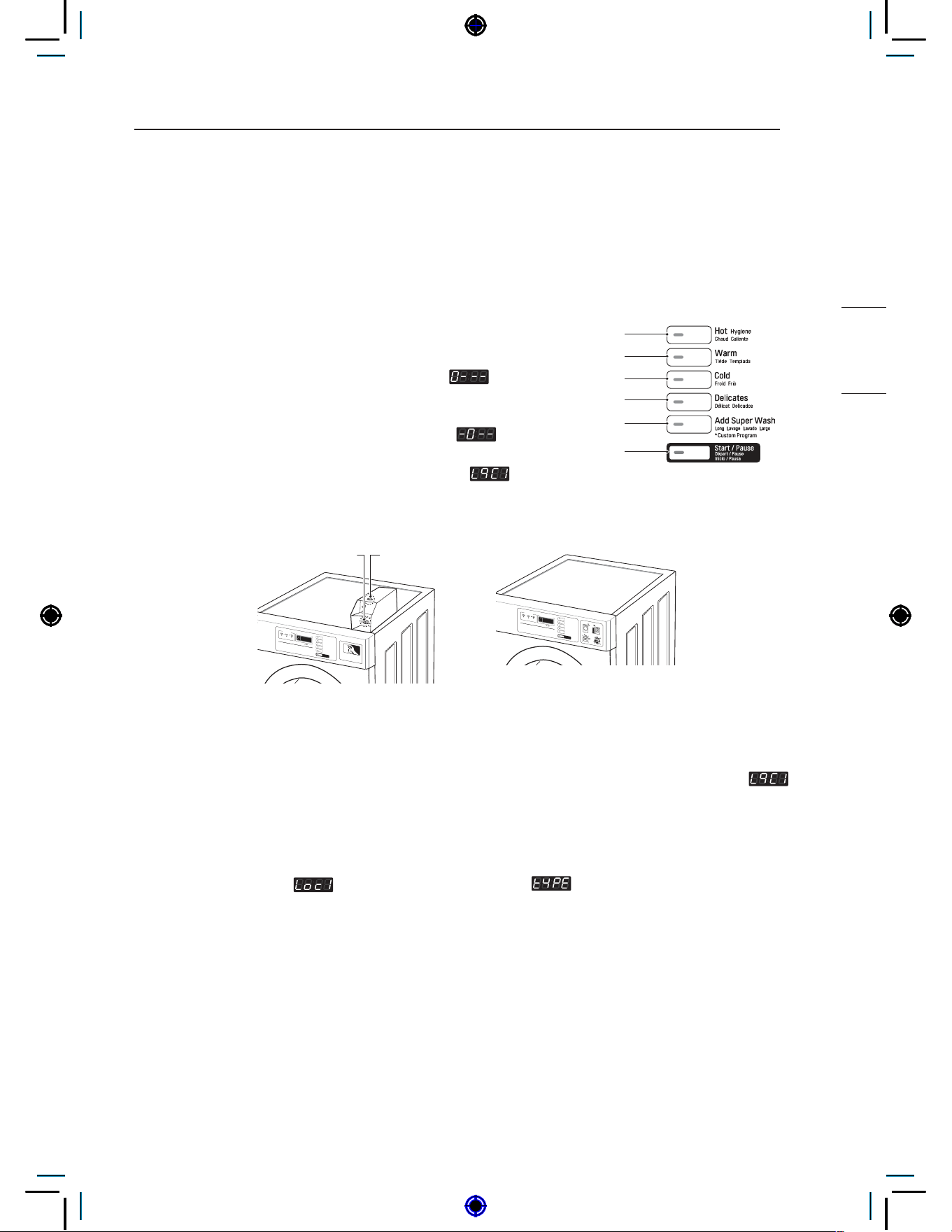
17
PROGRAMMING MODE
NON HEATER
PROGRAMMING MODE
: You can check machine information or change setting on Program setup, collect information data,
Diagnostic test.
There are two methods that you can enter programming mode.
How to enter Programming mode:
• Coin type – Turn on/off the toggle switch.
• Card type – Insert the service card.
• All types –
1
Press the 1st & 3rd button at the same time.
2
Press the 2nd & 3rd buttons to toggle numbers. Then,
press the 4th button to move to the next digit.
3
Press the Start button to finish password input.
* Default Password : 3000
<Control Panel Button>
1st
2nd
3rd
4th
5th
Start
Coin Vault
Openings close
Coin Box Key
- Coin type - - OPL type -
NOTE
• If you turn on the power without connecting meter case for the first time, the machine display
.
• When the machine is shipped from the factory, it is set in the coin type. You can change Card/Coin
type by button. (For more information refer to SETUP mode.)
• The machine will display PUSH for OPL type
• Price setting varies by country
• Set your country from
mode (Refer How to enter the )
• After EEPT, reset your country (Default country is EUK)
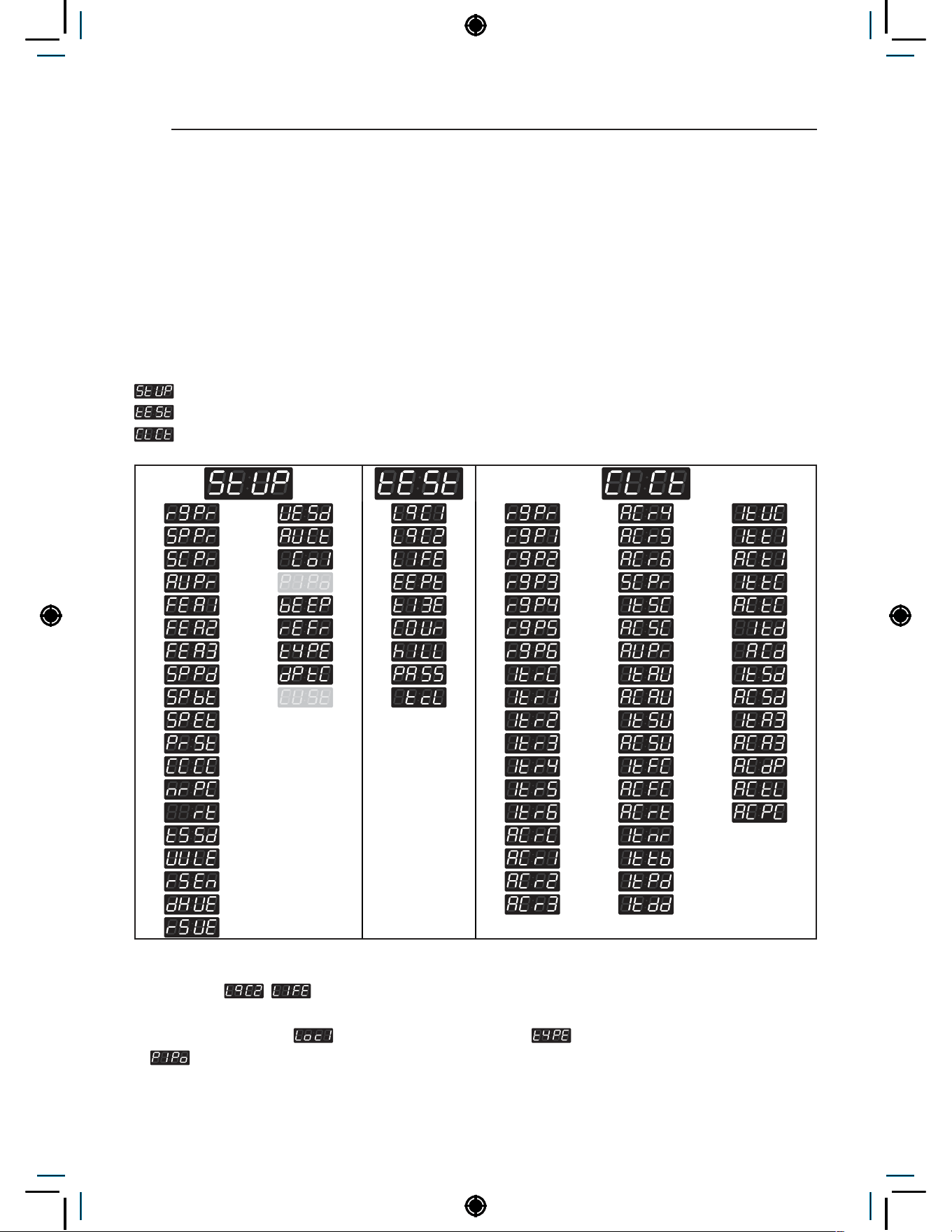
18
PROGRAMMING MODE
Structure of Programming mode – Card / Coin type
Algorithm flow chart shows how to control the programming mode.
Before program set, check the structure of the programming mode.
1
Turn on/off toggle switch or Insert service card, for entering set up mode (or follow OPL type
instructions).
2
Press Hot button to move to the upper level.
3
Press Warm (+) or Cold (-) button if you want to be at the same level.
4
Press Start button to enter the details of Set up or Diagnostic Tests.
is to set price value, time value, vend type, etc.
consists of line test, reset, free cycle, and kill cycle.
is to collect the usage data.
NOTE
• Do not use
, . (It is used only in inspecting the machine.)
• Price setting varies by country
• Set your country from
mode (Refer How to enter the )
•
This function is for Card type only.
• After EEPT, reset your country (Default country is EUK)
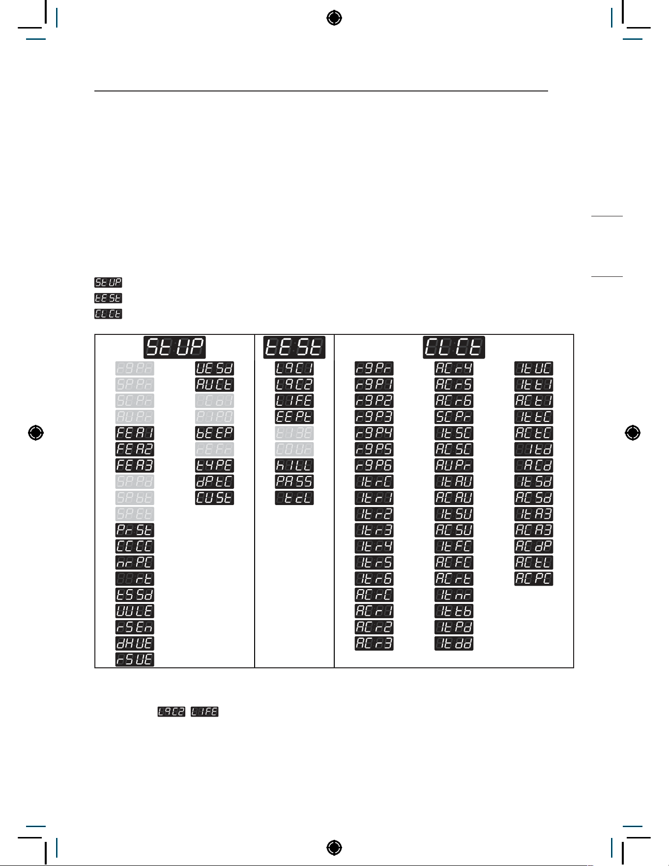
19
PROGRAMMING MODE
NON HEATER
Structure of Programming mode – OPL type
Algorithm flow chart shows how to control the programming mode.
Before program set, check the structure of the programming mode.
1
Turn on/off toggle switch or Insert service card, for entering set up mode (or follow OPL type
instructions).
2
Press Hot button to move to the upper level.
3
Press Warm (+) or Cold (-) button if you want to be at the same level.
4
Press Start button to enter the details of Set up or Diagnostic Tests.
is to set price value, time value, vend type, etc.
consists of line test, reset, free cycle, and kill cycle.
is to collect the usage data.
NOTE
• Do not use
, . (It is used only in inspecting the machine.)
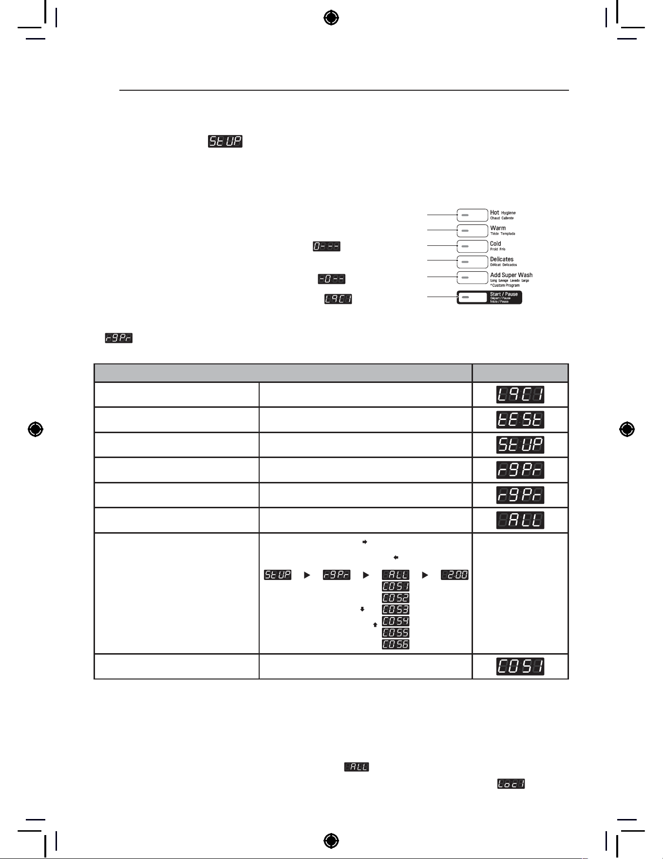
20
PROGRAMING MODE – SETUP MODE
PROGRAMING MODE – SETUP MODE
Setup Mode :
(display)
You can change washer vend price, cycle time, and cycle parameters, etc.
How to enter Programming mode:
• Coin type – Turn on/off the toggle switch.
• Card type – Insert the service card.
• All types –
1
Press the 1st & 3rd button at the same time.
2
Press the 2nd & 3rd buttons to toggle numbers. Then,
press the 4th button to move to the next digit.
3
Press the Start button to finish password input.
* Default Password : 3000
<Control Panel Button>
1st
2nd
3rd
4th
5th
Start
1. Regular Price Setup
How to set regular prices for all/each course.
Regular Price Setup Display
Enter SVC mode
Press 1st button
Press 2nd button
Press start button
Press 2nd button or 3rd button Until display shows
Press start button
Select the setting you want
Button functions:
Start button = Select
1st button = Go back a step
2nd button = Move up or
increase value
3rd button = Move down or
decrease value
Start button to select :
1st button to go back a step :
2nd button move up :
3rd button move to down :
Press Start to set the price The next course setting will be displayed.
NOTE
• Range : 0.00~10.00
• Increments : 0.1
• ALL is to select the default prices for all the
courses at once.
• Select individual price for COS1~6.
• COS1 : Hot
• COS2 : Warm
• COS3 : Cold
• COS4 : Delicates
• COS5, COS6 : Heater model only
* Individual course prices are prioritized above
.
− Set your currency type using
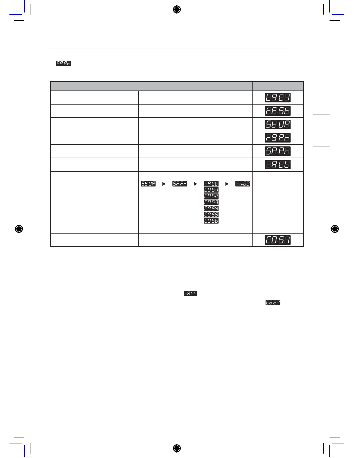
21
PROGRAMING MODE – SETUP MODE
NON HEATER
2. Special Price Setup
How to set special prices for all/each course.
Special Price Setup Display
Enter SVC mode
Press 1st button
Press 2nd button
Press start button
Press 2nd button or 3rd button Until display shows
Press start button
Select the setting you want
Button functions:
Start button = Select
1st button = Go back a step
2nd button = Move up or
increase value
3rd button = Move down or
decrease value
Press Start to set the price The next course setting will be displayed.
NOTE
• Range : 0.00~10.00
• Increments : 0.1
• ALL is to select the default prices for all the
courses at once.
• Select individual price for COS1~6.
• COS1 : Hot
• COS2 : Warm
• COS3 : Cold
• COS4 : Delicates
• COS5, COS6 : Heater model only
* Individual course prices are prioritized above
.
− Set your currency type using
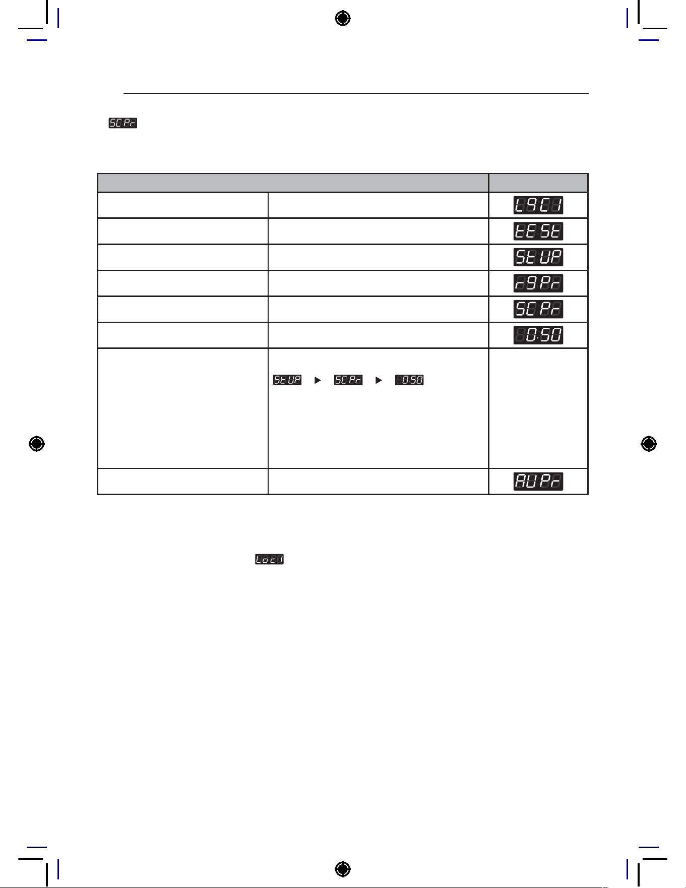
22
PROGRAMING MODE – SETUP MODE
3. Add Super Wash Price Setup
How to set Add Super Wash Price.
* Add Super Wash is used to add extra wash, rinse, or both (only in Pay type).
Add Super Wash Price Setup Display
Enter SVC mode
Press 1st button
Press 2nd button
Press start button
Press 2nd button or 3rd button Until display shows
Press start button
Select the setting you want
Button functions:
Start button = Select
1st button = Go back a step
2nd button = Move up or
increase value
3rd button = Move down or
decrease value
Press Start to set the price The next menu setting will be displayed.
NOTE
• Range : 0.00~10.00
• Increments : 0.1
− Set your currency type using

23
PROGRAMING MODE – SETUP MODE
NON HEATER
4. Auto Dosing Price Setup
How to set Auto Dosing Price.
* Auto dosing is used to inject detergent/chemicals using external pumps (only in Pay type).
Auto Dosing Price Setup Display
Enter SVC mode
Press 1st button
Press 2nd button
Press start button
Press 2nd button or 3rd button Until display shows
Press start button
Select the setting you want
Button functions:
Start button = Select
1st button = Go back a step
2nd button = Move up or
increase value
3rd button = Move down or
decrease value
Press Start to set the price The next menu setting will be displayed.
NOTE
• Range : 0.00~10.00
• Increments : 0.1
− Set your currency type using
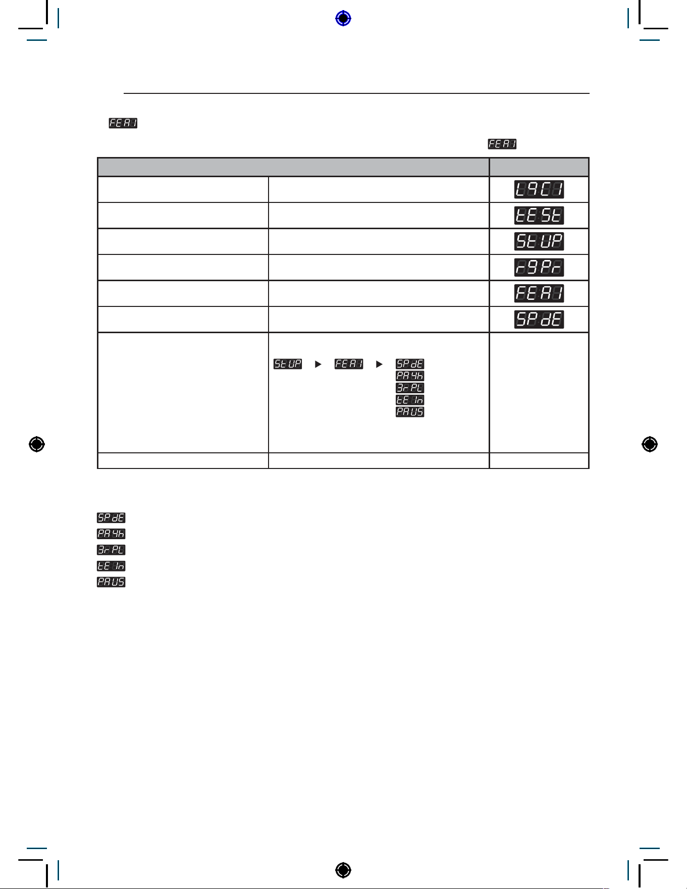
24
PROGRAMING MODE – SETUP MODE
5. Features of the Machine (1st Set)
How to set up Features of the Machine. There are multiple setup features under .
Features of the Machine (1st Set) Display
Enter SVC mode
Press 1st button
Press 2nd button
Press start button
Press 2nd button or 3rd button Until display shows
Press start button
Select the setting you want
Button functions:
Start button = Select
1st button = Go back a step
2nd button = Move up or
increase value
3rd button = Move down or
decrease value
Press Start to set sub-function
NOTE
: Special price day enable or disable
: Easy entry payment cycle kill enable or disable
: Maximum rpm limit enable or disable
: Twin spray enable or disable
: Pause function enable or disable
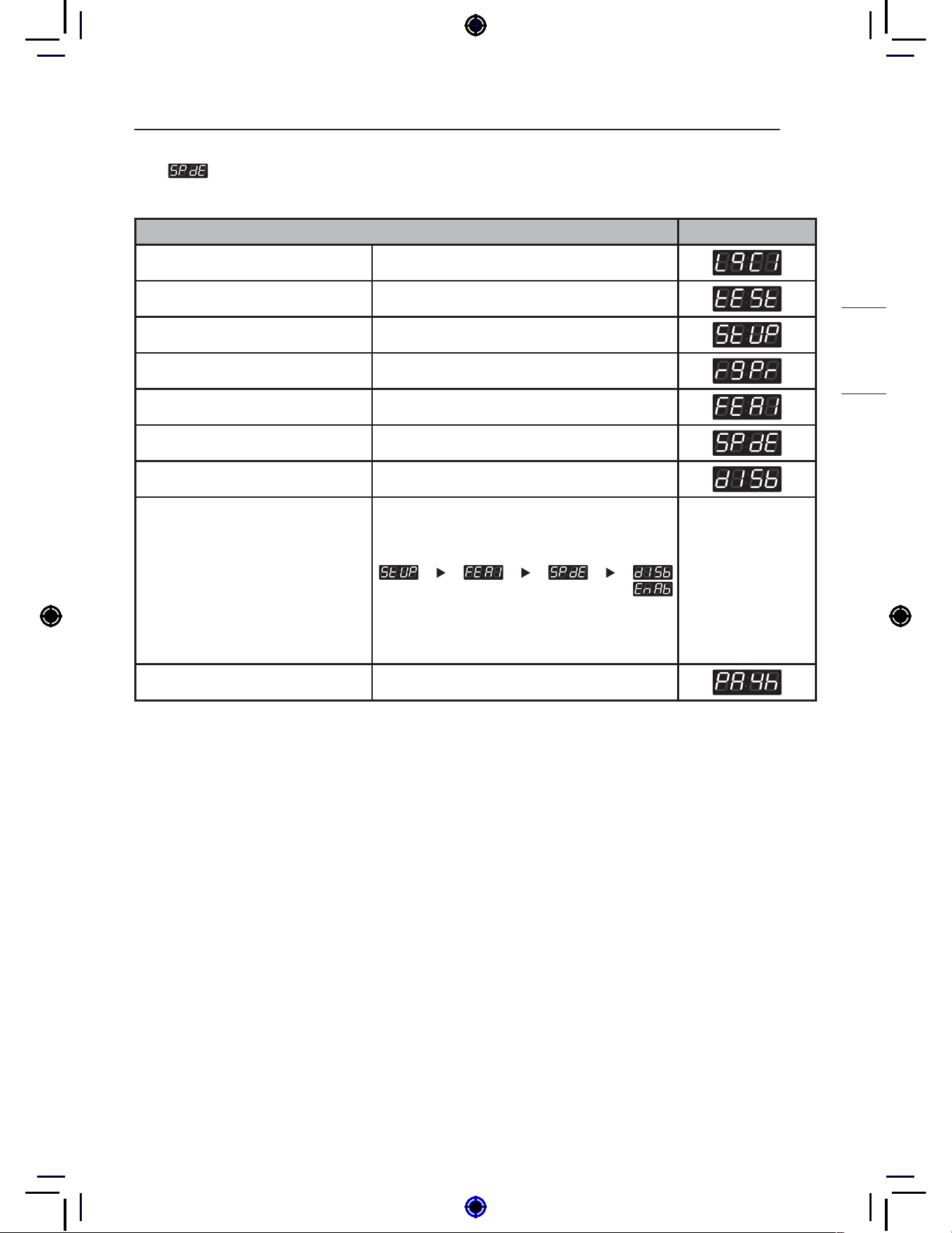
25
PROGRAMING MODE – SETUP MODE
NON HEATER
5-1. Special Price Day Setup
Special Price Day Setup can be used to enable/disable the use of special prices.
Special Price Day Setup Display
Enter SVC mode
Press 1st button
Press 2nd button
Press start button
Press 2nd button or 3rd button Until display shows
Press start button
Press start button
Select the setting you want
Button functions:
Start button = Select
1st button = Go back a step
2nd button = Move up or
increase value
3rd button = Move down or
decrease value
Press Start to enable or disable The next menu setting will be displayed.
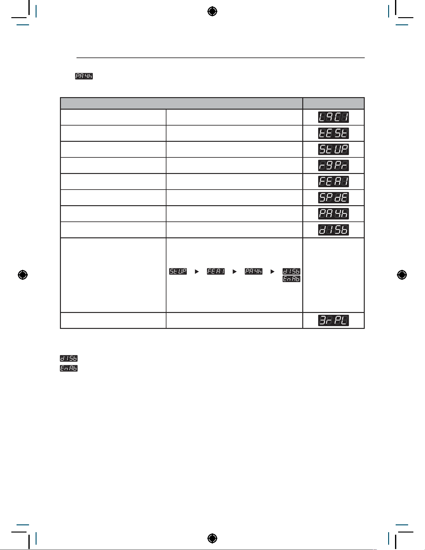
26
PROGRAMING MODE – SETUP MODE
5-2. Easy Entry Payment Cycle Kill Setup
Easy entry cycle kill can be enabled or disabled in the payment cycle
Easy Entry Payment Cycle Kill Setup Display
Enter SVC mode
Press 1st button
Press 2nd button
Press start button
Press 2nd button or 3rd button Until display shows
Press start button
Press 2nd button or 3rd button Until display shows
Press start button
Select the setting you want
Button functions:
Start button = Select
1st button = Go back a step
2nd button = Move up or
increase value
3rd button = Move down or
decrease value
Press Start to enable or disable The next menu setting will be displayed.
NOTE
Shortcut key not available
Shortcut key available
• Shortcut key : Press and hold the start button for at least 3 seconds.
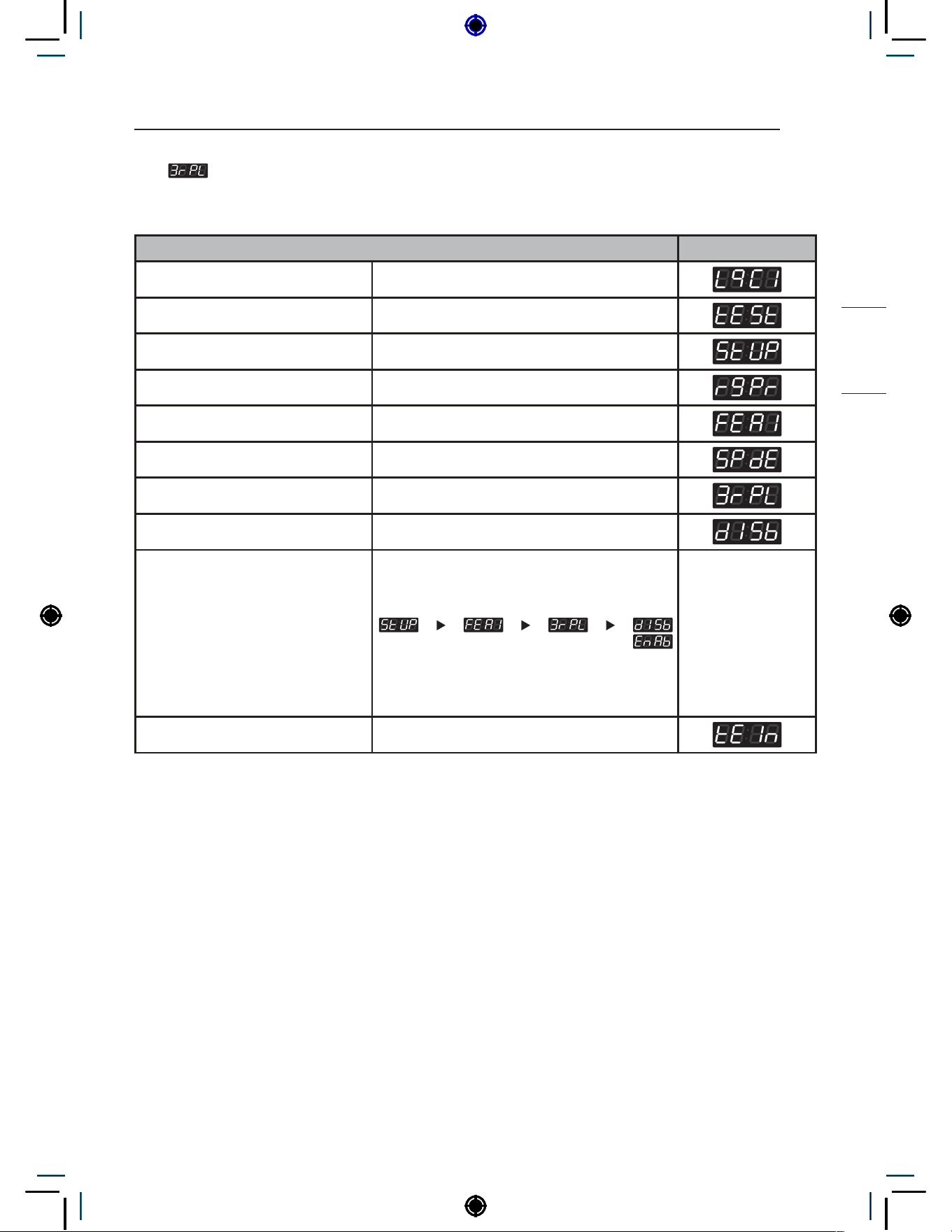
27
PROGRAMING MODE – SETUP MODE
NON HEATER
5-3. Max RPM Limit Setup
Max RPM Limit Setup can be used to enable/disable the ability to limit the max RPM during spin
process.
Max RPM Limitation Setup Display
Enter SVC mode
Press 1st button
Press 2nd button
Press start button
Press 2nd button or 3rd button Until display shows
Press start button
Press 2nd button or 3rd button Until display shows
Press start button
Select the setting you want
Button functions:
Start button = Select
1st button = Go back a step
2nd button = Move up or
increase value
3rd button = Move down or
decrease value
Press Start to enable or disable The next menu setting will be displayed.
NOTE
If enabled, the max RPM will adjust according to the laundry load.
Max RPM will be reduced for highly unbalanced loads.
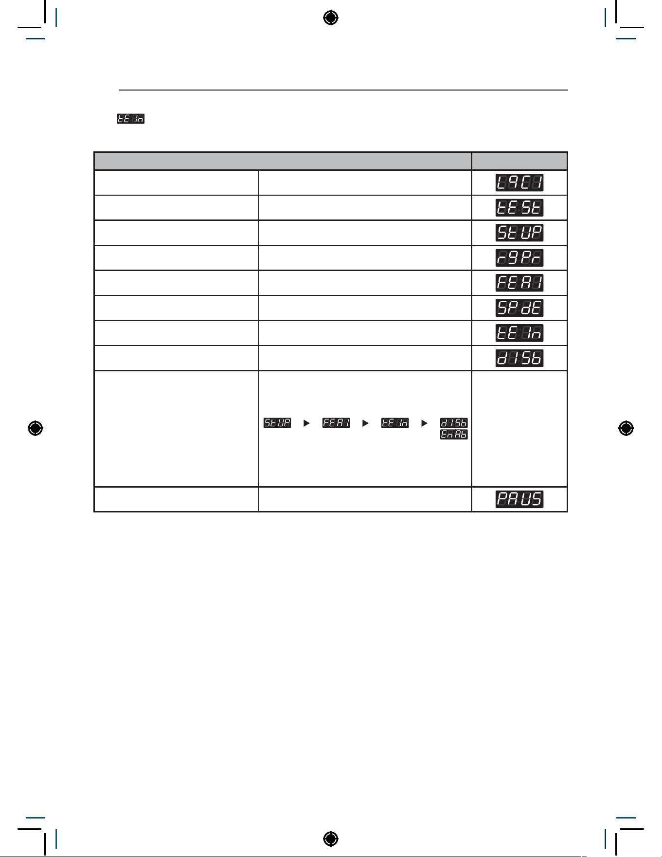
28
PROGRAMING MODE – SETUP MODE
5-4. Twin Spray Setup
Twin Spray Setup can be used to enable/disable water circulation during tumble.
Twin Spray Setup Display
Enter SVC mode
Press 1st button
Press 2nd button
Press start button
Press 2nd button or 3rd button Until display shows
Press start button
Press 2nd button or 3rd button Until display shows
Press start button
Select the setting you want
Button functions:
Start button = Select
1st button = Go back a step
2nd button = Move up or
increase value
3rd button = Move down or
decrease value
Press Start to enable or disable The next menu setting will be displayed.
NOTE
For better wash performance, twin spray pumps up water from the bottom of the tub to spray soapy water
on laundry while tumbling.

29
PROGRAMING MODE – SETUP MODE
NON HEATER
5-5. Pause Function Setup
Pause Function Setup can be used to enable/disable the ability to pause the cycle when pressing
the start/pause button.
Pause Function Setup Display
Enter SVC mode
Press 1st button
Press 2nd button
Press start button
Press 2nd button or 3rd button Until display shows
Press start button
Press 2nd button or 3rd button Until display shows
Press start button
Select the setting you want
Button functions:
Start button = Select
1st button = Go back a step
2nd button = Move up or
increase value
3rd button = Move down or
decrease value
Press Start to enable or disable The next menu setting will be displayed.
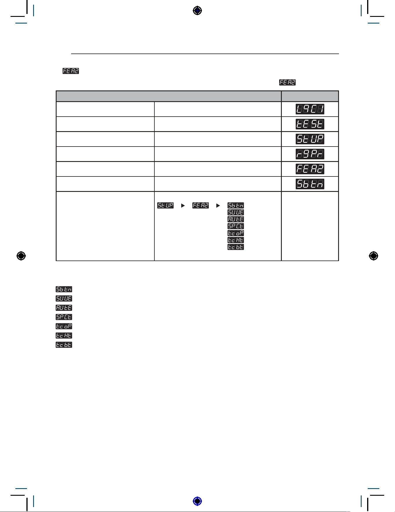
30
PROGRAMING MODE – SETUP MODE
6. Features of the Machine (2nd Set)
How to set up features of the machine. There are multiple setup features under .
Features of the Machine (2nd Set) Display
Enter SVC mode
Press 1st button
Press 2nd button
Press start button
Press 2nd button or 3rd button Until display shows
Press start button
Select the setting you want
Button functions:
Start button = Select
1st button = Go back a step
2nd button = Move up or
increase value
3rd button = Move down or
decrease value
NOTE
: 5th button fuction select (Add super wash or Auto dosing charging)
: Add super wash enable or disable
: Auto dosing function enable or disable
: Add super wash type
: Tub clean load detection enable or disable
: Tub clean heater usage enable or disable
: Tub clean easy entry function enable or disable
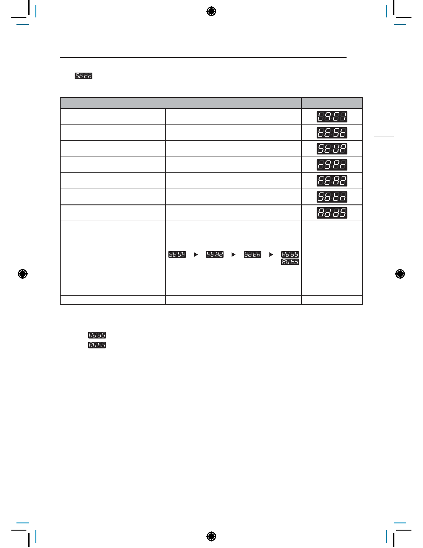
31
PROGRAMING MODE – SETUP MODE
NON HEATER
6-1. 5th Button Type Setup
5th Button Type Setup can be used to set the function of the 5th button.
5th Button Type Setup Display
Enter SVC mode
Press 1st button
Press 2nd button
Press start button
Press 2nd button or 3rd button Until display shows
Press start button
Press 2nd button or 3rd button Until display shows
Select the setting you want
Button functions:
Start button = Select
1st button = Go back a step
2nd button = Move up or
increase value
3rd button = Move down or
decrease value
Press Start to set sub-fuction Display returns to standby mode.
NOTE
Setting to
will make the 5th button function as Add Super Wash.
Setting to
will make the 5th button function as payment for auto dosing.

32
PROGRAMING MODE – SETUP MODE
6-2. Add Super Wash Setup
Add Super Wash Setup can be used to enable/disable the super wash function.
* Add Super Wash is used to add extra wash, rinse, or both (only used in Pay type).
Add Super Wash Setup Display
Enter SVC mode
Press 1st button
Press 2nd button
Press start button
Press 2nd button or 3rd button Until display shows
Press start button
Press 2nd button or 3rd button Until display shows
Press start button
Select the setting you want
Button functions:
Start button = Select
1st button = Go back a step
2nd button = Move up or
increase value
3rd button = Move down or
decrease value
Press Start to enable or disable The next menu setting will be displayed.

33
PROGRAMING MODE – SETUP MODE
NON HEATER
6-3. Auto Dosing Setup
Auto Dosing Setup can be used to enable/disable the Auto dosing function.
Auto Dosing Setup Display
Enter SVC mode
Press 1st button
Press 2nd button
Press start button
Press 2nd button or 3rd button Until display shows
Press start button
Press 2nd button or 3rd button Until display shows
Press start button
Select the setting you want
Button functions:
Start button = Select
1st button = Go back a step
2nd button = Move up or
increase value
3rd button = Move down or
decrease value
Press Start to enable or disable The next menu setting will be displayed.
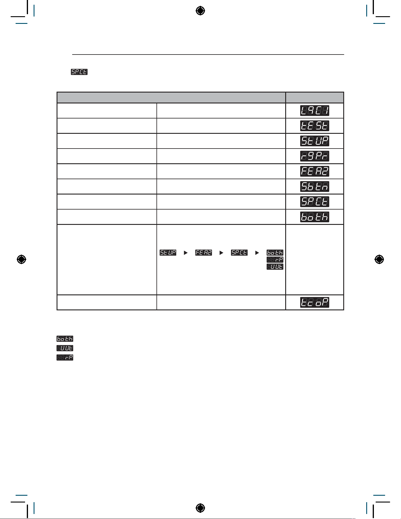
34
PROGRAMING MODE – SETUP MODE
6-4. Add Super Wash Type Setup
Add Super Wash Type Setup can be used to add extra wash cycle, rinse cycle, or both.
Add Super Wash Type Setup Display
Enter SVC mode
Press 1st button
Press 2nd button
Press start button
Press 2nd button or 3rd button Until display shows
Press start button
Press 2nd button or 3rd button Until display shows
Press start button
Select the setting you want
Button functions:
Start button = Select
1st button = Go back a step
2nd button = Move up or
increase value
3rd button = Move down or
decrease value
Press Start to set sub-fuction The next menu setting will be displayed.
NOTE
: Both (Increase wash time and rinse once more)
: Increase wash time
: Rinse once more

35
PROGRAMING MODE – SETUP MODE
NON HEATER
6-5. Tub Clean Load Detection Setup
Tub Clean Load Detection Setup can be used to enable/disable the ability to detect laundry load
during tub clean. If enabled, the washer will detect whether or not a load is present in the washer.
Tub Clean Load Detection Setup Display
Enter SVC mode
Press 1st button
Press 2nd button
Press start button
Press 2nd button or 3rd button Until display shows
Press start button
Press 2nd button or 3rd button Until display shows
Press start button
Select the setting you want
Button functions:
Start button = Select
1st button = Go back a step
2nd button = Move up or
increase value
3rd button = Move down or
decrease value
Press Start to enable or disable The next menu setting will be displayed.

36
PROGRAMING MODE – SETUP MODE
6-6. Tub Clean Heater Setup
Tub Clean Heater Setup can be used to enable/disable the ability to use the heater during tub clean.
If enabled, the heater will be used for the tub clean.
Tub Clean Heater Setup Display
Enter SVC mode
Press 1st button
Press 2nd button
Press start button
Press 2nd button or 3rd button Until display shows
Press start button
Press 2nd button or 3rd button Until display shows
Press start button
Select the setting you want
Button functions:
Start button = Select
1st button = Go back a step
2nd button = Move up or
increase value
3rd button = Move down or
decrease value
Press Start to enable or disable The next menu setting will be displayed.

37
PROGRAMING MODE – SETUP MODE
NON HEATER
6-7. Tub Clean Button Setup
Tub Clean Button Setup can be used to enable/disable the easy entry function for the new tub clean
Tub Clean Button Setup Display
Enter SVC mode
Press 1st button
Press 2nd button
Press start button
Press 2nd button or 3rd button Until display shows
Press start button
Press 2nd button or 3rd button Until display shows
Press start button
Select the setting you want
Button functions:
Start button = Select
1st button = Go back a step
2nd button = Move up or
increase value
3rd button = Move down or
decrease value
Press Start to enable or disable The next menu setting will be displayed.
NOTE
Shortcut key not available
Shortcut key available (Press and hold 1st and 2nd button in same time)
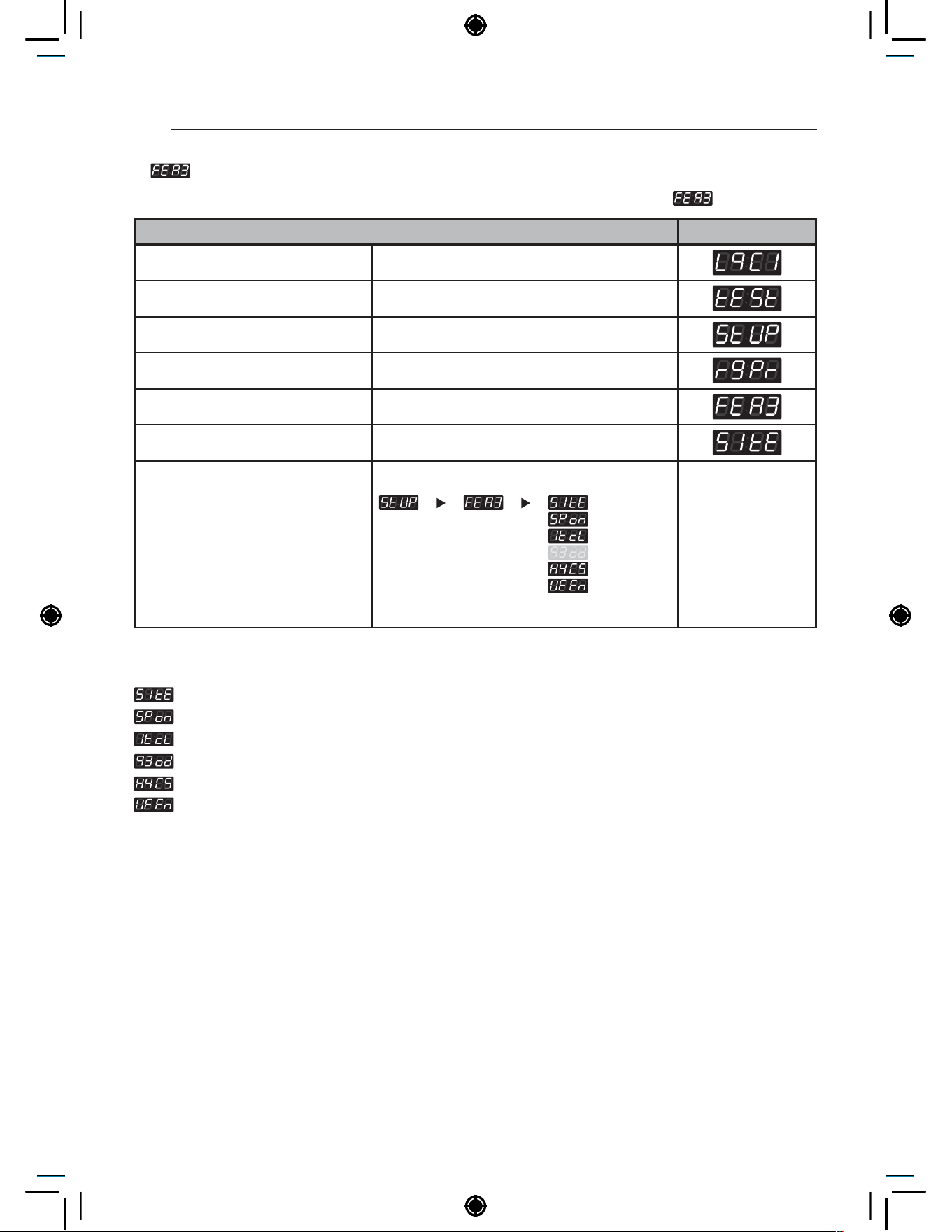
38
PROGRAMING MODE – SETUP MODE
7. Features of the Machine (3rd Set)
How to set up features of the machine. There are multiple setup features under .
Features of the Machine (3rd Set) Display
Enter SVC mode
Press 1st button
Press 2nd button
Press start button
Press 2nd button or 3rd button Until display shows
Press start button
Select the setting you want
Button functions:
Start button = Select
1st button = Go back a step
2nd button = Move up or
increase value
3rd button = Move down or
decrease value
NOTE
: Spin type
: Spin only easy entry function enable or disable
: Initial tub clean enable or disable
: quick mode enable or disable
: Hygiene Course enable or disable
: UE Error enable or disable
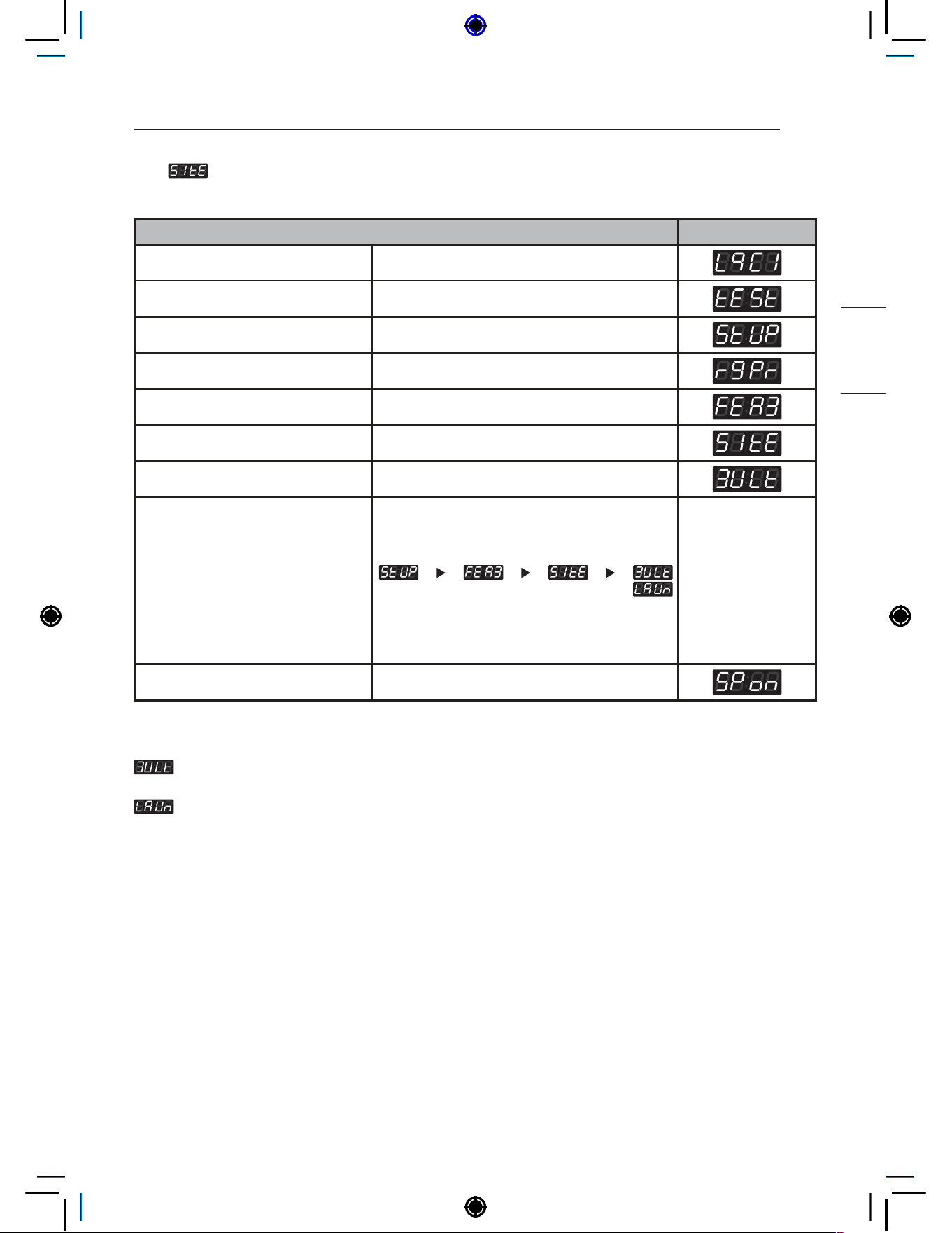
39
PROGRAMING MODE – SETUP MODE
NON HEATER
7-1. Spin Type Setup
Spin Type Setup can be used to select spin type between multi-housing type and coin laundry type.
Spin Type Setup Display
Enter SVC mode
Press 1st button
Press 2nd button
Press start button
Press 2nd button or 3rd button Until display shows
Press start button
Press start button
Select the setting you want
Button functions:
Start button = Select
1st button = Go back a step
2nd button = Move up or
increase value
3rd button = Move down or
decrease value
Press Start to set spin type The next menu setting will be displayed.
NOTE
Vibration is lower than Coin type, but spin entry time may be longer. This setting is recommended for
locations with bad flooring conditions, such as apartments or dormitories.
Vibration is higher than Multi type, but spin entry time will be shorter. This setting is recommended for
locations with good flooring conditions, such as laundromats.
• Long spin entry time means an increase in total cycle time.

40
PROGRAMING MODE – SETUP MODE
7-2. Spin Only Easy Entry Setup
Spin Only Easy Entry Setup can be used to enable/disable the easy entry function for the spin only.
Spin Only Easy Entry Setup Display
Enter SVC mode
Press 1st button
Press 2nd button
Press start button
Press 2nd button or 3rd button Until display shows
Press start button
Press 2nd button or 3rd button Until display shows
Press start button
Select the setting you want
Button functions:
Start button = Select
1st button = Go back a step
2nd button = Move up or
increase value
3rd button = Move down or
decrease value
Press Start to enable or disable The next menu setting will be displayed.
NOTE
• In the case when the washer completes a cycle but the clothes are still very wet, the spin only feature
will be activated and ready for use.
• This condition is based on the program of the machine, in some cases it may not be available. Even if
the spin only is not available to the customer after a load, it does not mean the washer requires service.
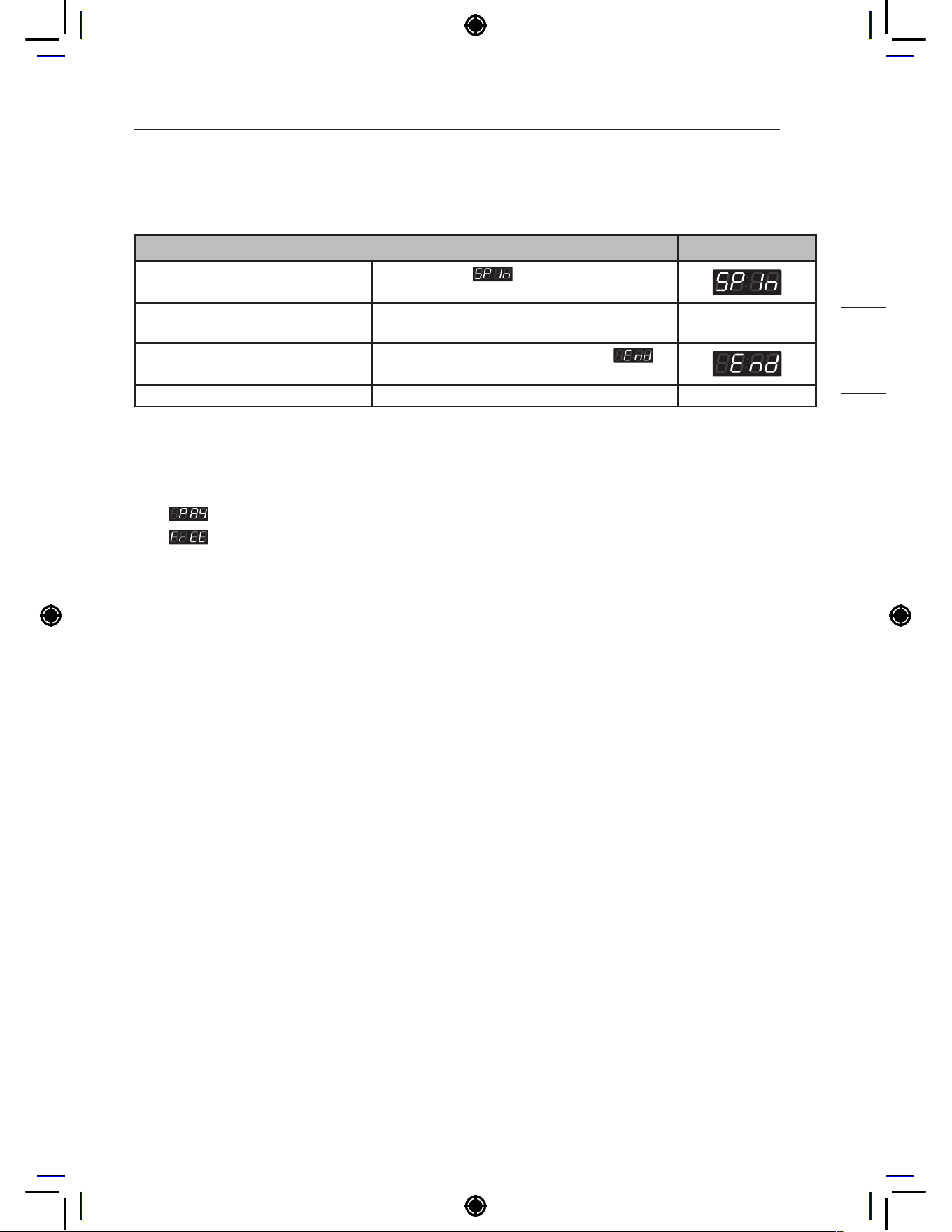
41
PROGRAMING MODE – SETUP MODE
NON HEATER
7-3. How to use Spin only easy entry
When the washer completes a cycle but the clothes are still very wet, please run a spin only cycle
using the easy entry function.
Spin only easy entry Display
Press and hold 5th button for at
least 3 seconds.
Display shows
if the function is
activated.
Press start button
Display will show the remaining time and the
Spin only cycle starts.
When the Spin only cycle is finished,
is
displayed with beeping.
Go back to ready mode.
NOTE
• There will be no visible indication even when the Spin Only Easy Entry function becomes activated. The
machine will be in ready/idle mode.
−
type: PUSH is displayed.
−
type: PUSH is displayed.

42
PROGRAMING MODE – SETUP MODE
7-4. Pre clean button setup
Pre clean button setup can be used to enable/disable button that entry a short tub wash cycle.
Pre clean button setup Display
Enter SVC mode
Press 1st button
Press 2nd button
Press start button
Press 2nd button or 3rd button Until display shows
Press start button
Press 2nd button or 3rd button Until display shows
Press start button
Select the setting you want
Button functions:
Start button = Select
1st button = Go back a step
2nd button = Move up or
increase value
3rd button = Move down or
decrease value
Press Start to enable or disable The next menu setting will be displayed.
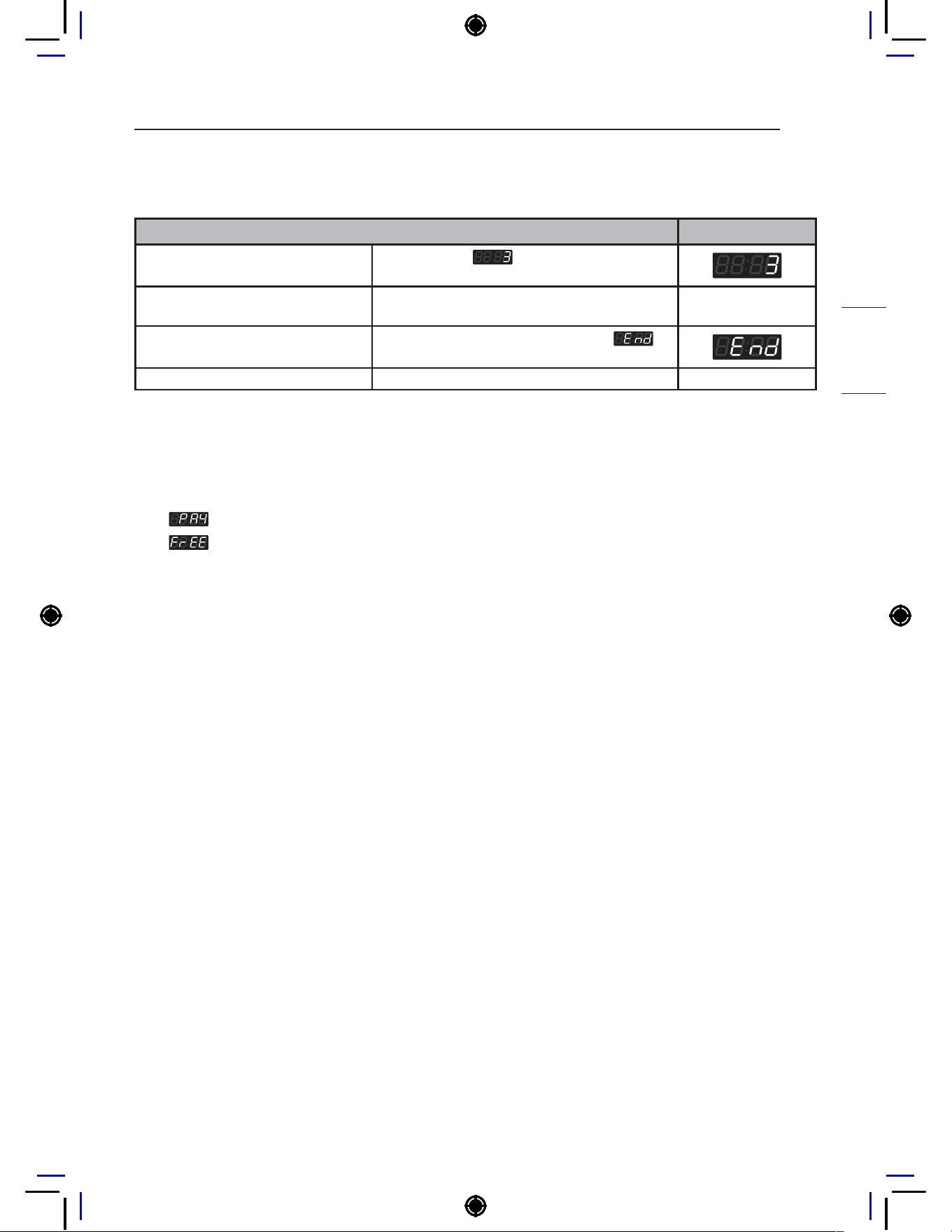
43
PROGRAMING MODE – SETUP MODE
NON HEATER
7-5. How to use Pre clean
When the customer or manager want to use short wash the tub before the cycle, please run a pre clean cycle.
Pre clean entry Display
Press and hold 1st button for at
least 3 seconds.
Display shows
if the function is
activated.
Press start button
Display will show the remaining time and the
Spin only cycle starts.
When the Spin only cycle is finished,
is
displayed with beeping.
Go back to ready mode.
NOTE
• There will be no visible indication even when the Pre clean becomes activated. The machine will be in
ready/idle mode.
• After one cycle, additional cycles are not possible continuously.
−
type: PUSH is displayed.
−
type: PUSH is displayed.

44
PROGRAMING MODE – SETUP MODE
7-6. quick mode setup
Quick mode setup can be used to enable/disable the use quick cycle.
quick mode setup Display
Enter SVC mode
Press 1st button
Press 2nd button
Press start button
Press 2nd button or 3rd button Until display shows
Press start button
Press 2nd button or 3rd button Until display shows
Press start button
Select the setting you want
Button functions:
Start button = Select
1st button = Go back a step
2nd button = Move up or
increase value
3rd button = Move down or
decrease value
Press Start to enable or disable The next menu setting will be displayed.
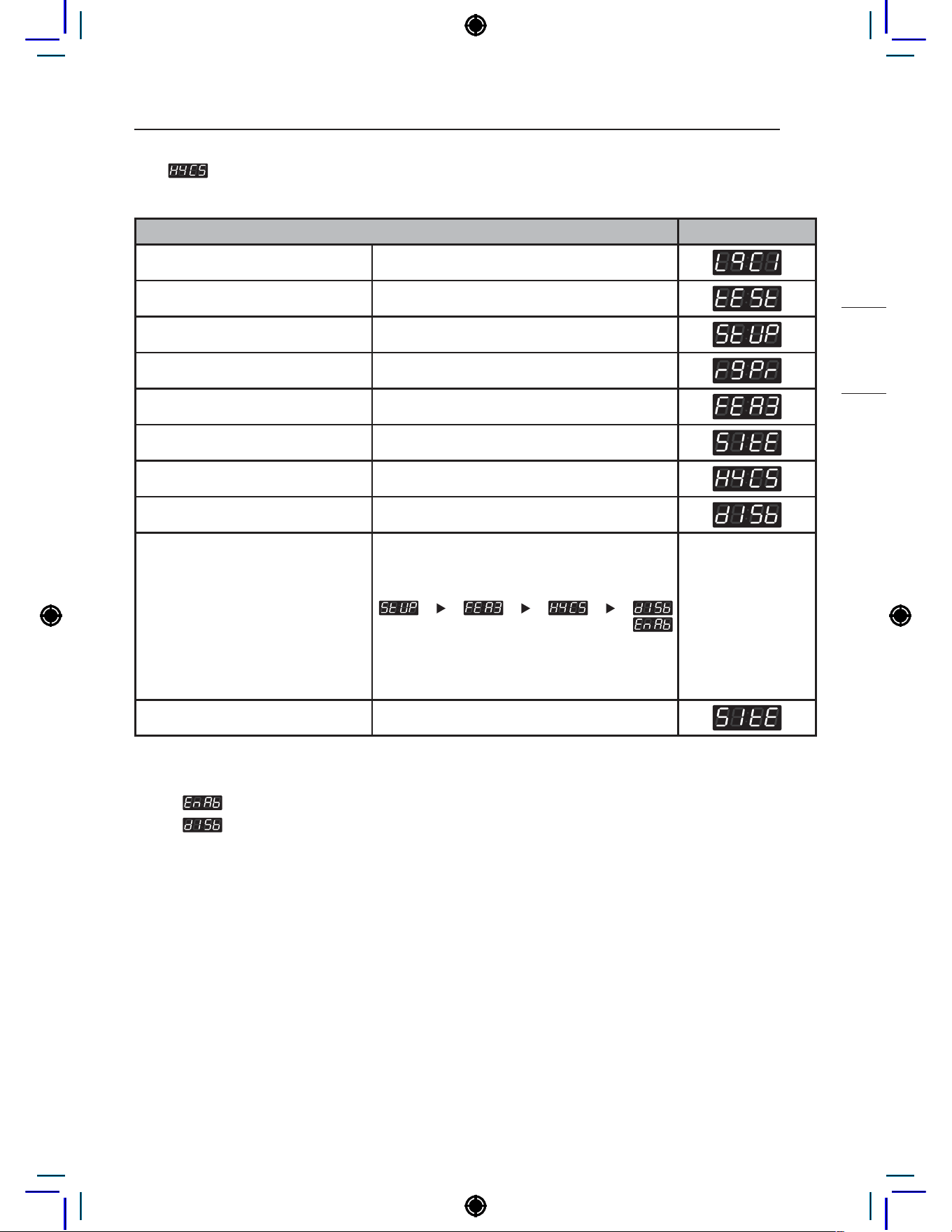
45
PROGRAMING MODE – SETUP MODE
NON HEATER
7-7. hygiene cycle button setup
hygiene cycle button setup can be used to set the function of the 1st button.
hygiene cycle button setup Display
Enter SVC mode
Press 1st button
Press 2nd button
Press start button
Press 2nd button or 3rd button Until display shows
Press start button
Press 2nd button or 3rd button Until display shows
Press start button
Select the setting you want
Button functions:
Start button = Select
1st button = Go back a step
2nd button = Move up or
increase value
3rd button = Move down or
decrease value
Press Start to enable or disable The next menu setting will be displayed.
NOTE
Setting
to will make the 1th button function as Hygiene cycle.
Setting
to will make the 1th button function as Hot cycle.
The hygiene cycle is a heating cycle that, like tub clean cycle, may shut down if several units are operated
simultaneously.

46
PROGRAMING MODE – SETUP MODE
7-8. UE Error Display Setup
The UE error display set up is used to enable or disable the UE function.
UE Error Display Setup Display
Enter SVC mode
Press 1st button
Press 2nd button
Press start button
Press 2nd button or 3rd button Until display shows
Press start button
Press 2nd button or 3rd button Until display shows
Press start button
Select the setting you want
Button functions:
Start button = Select
1st button = Go back a step
2nd button = Move up or
increase value
3rd button = Move down or
decrease value
Press Start to enable or disable The next menu setting will be displayed.
NOTE
•
UE will not displayed.
•
UE will be displayed If the spin entry is failed within displayed time+cut off time( ). After UE
is displayed press the start button one time and the machine will return to standby mode. The spin only
entry feature will be active for this cycle following a UE. Refer to 7-3 of this manual on how to use the
Spin only easy entry feature.
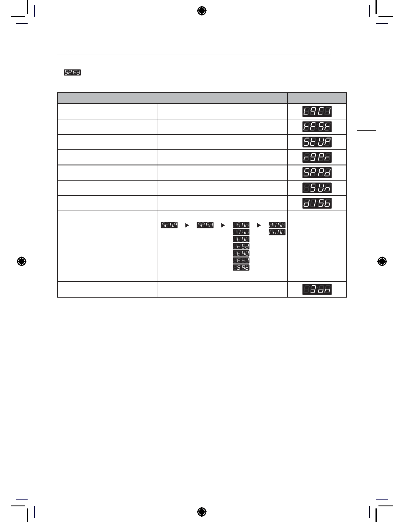
47
PROGRAMING MODE – SETUP MODE
NON HEATER
8. Special Price Day Setup
Special Price Day Setup can be used to select which days to apply special prices.
Special Price Day Setup Display
Enter SVC mode
Press 1st button
Press 2nd button
Press start button
Press 2nd button or 3rd button Until display shows
Press start button
Press Start button
Select the setting you want
Button functions:
Start button = Select
1st button = Go back a step
2nd button = Move up or
increase value
3rd button = Move down or
decrease value
Press Start to enable or disable The next menu setting will be displayed.
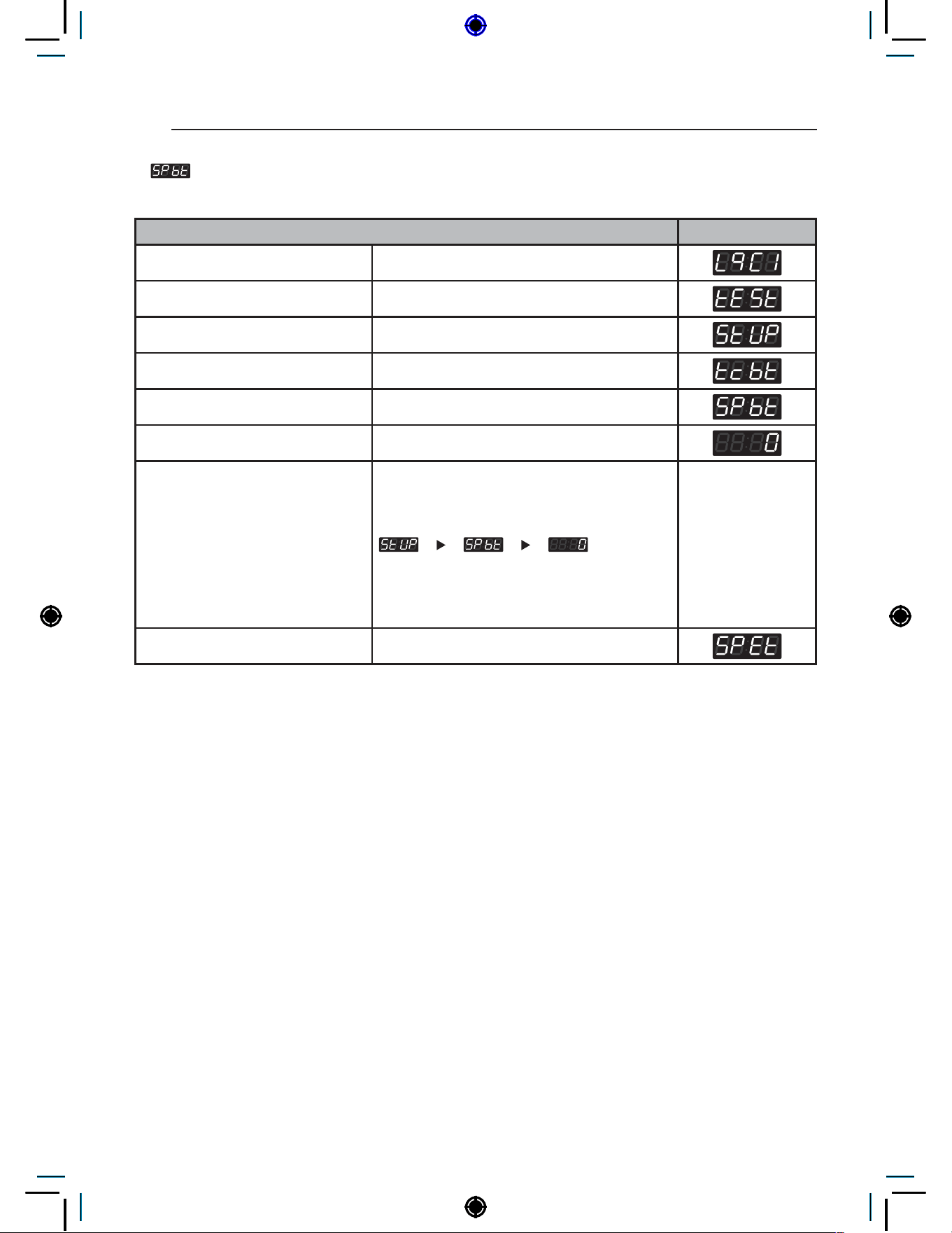
48
PROGRAMING MODE – SETUP MODE
9. Special Price Beginning Time Setup
Special Price Beginning Time Setup can be used to set the start time of special prices.
Special Price Beginning Time Setup Display
Enter SVC mode
Press 1st button
Press 2nd button
Press start button
Press 2nd button or 3rd button Until display shows
Press start button
Select the setting you want
Button functions:
Start button = Select
1st button = Go back a step
2nd button = Move up or
increase value
3rd button = Move down or
decrease value
Press Start to set time The next menu setting will be displayed.
NOTE
• Make sure to set up the Time feature before using this feature.
• Range : 0~23 hr
• Increments : 1
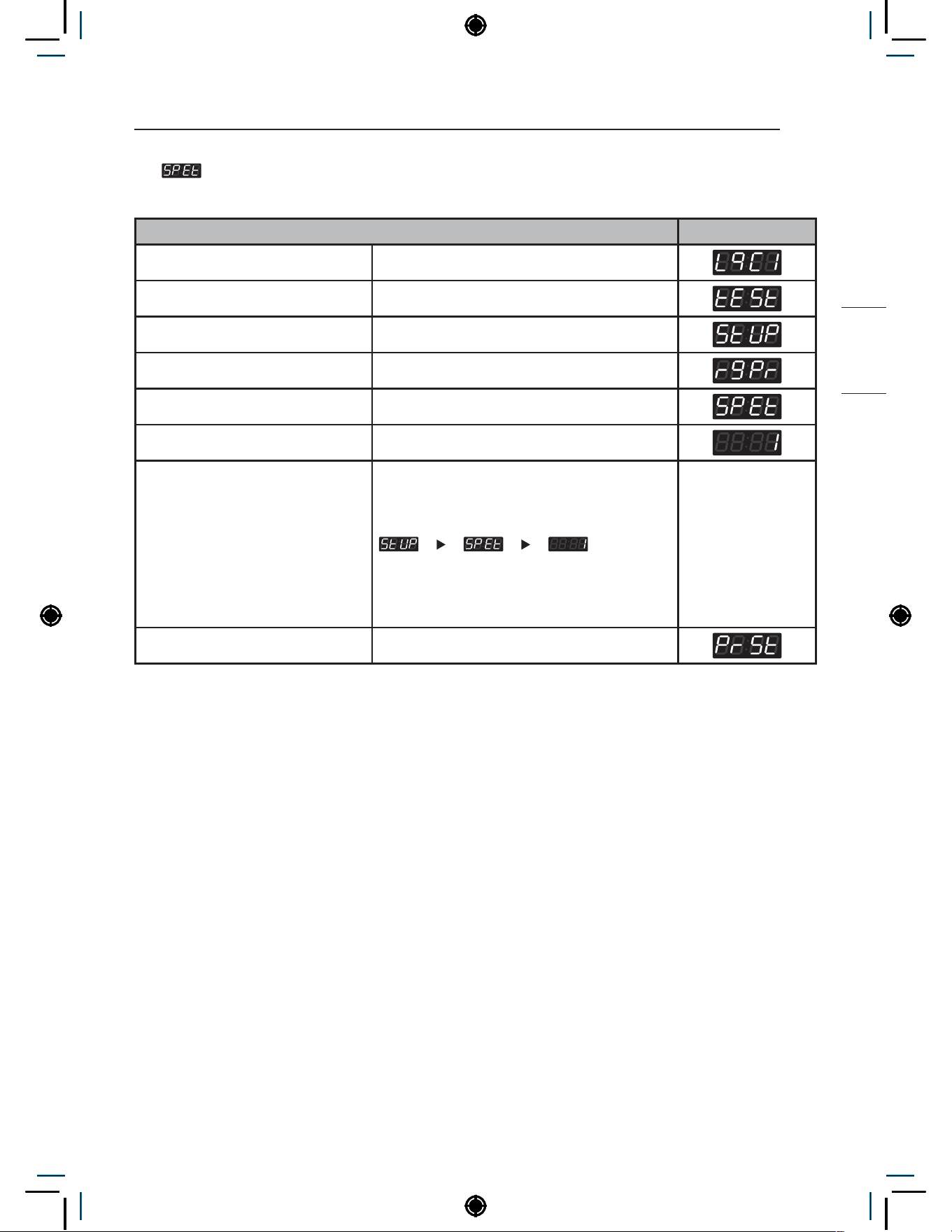
49
PROGRAMING MODE – SETUP MODE
NON HEATER
10. Special Price Ending Time Setup
Special Price Ending Time Setup can be used to set the end time for special prices.
Special Price Ending Time Setup Display
Enter SVC mode
Press 1st button
Press 2nd button
Press start button
Press 2nd button or 3rd button Until display shows
Press start button
Select the setting you want
Button functions:
Start button = Select
1st button = Go back a step
2nd button = Move up or
increase value
3rd button = Move down or
decrease value
Press Start to set time The next menu setting will be displayed.
NOTE
• Range : 1~24 hr
• Increments : 1
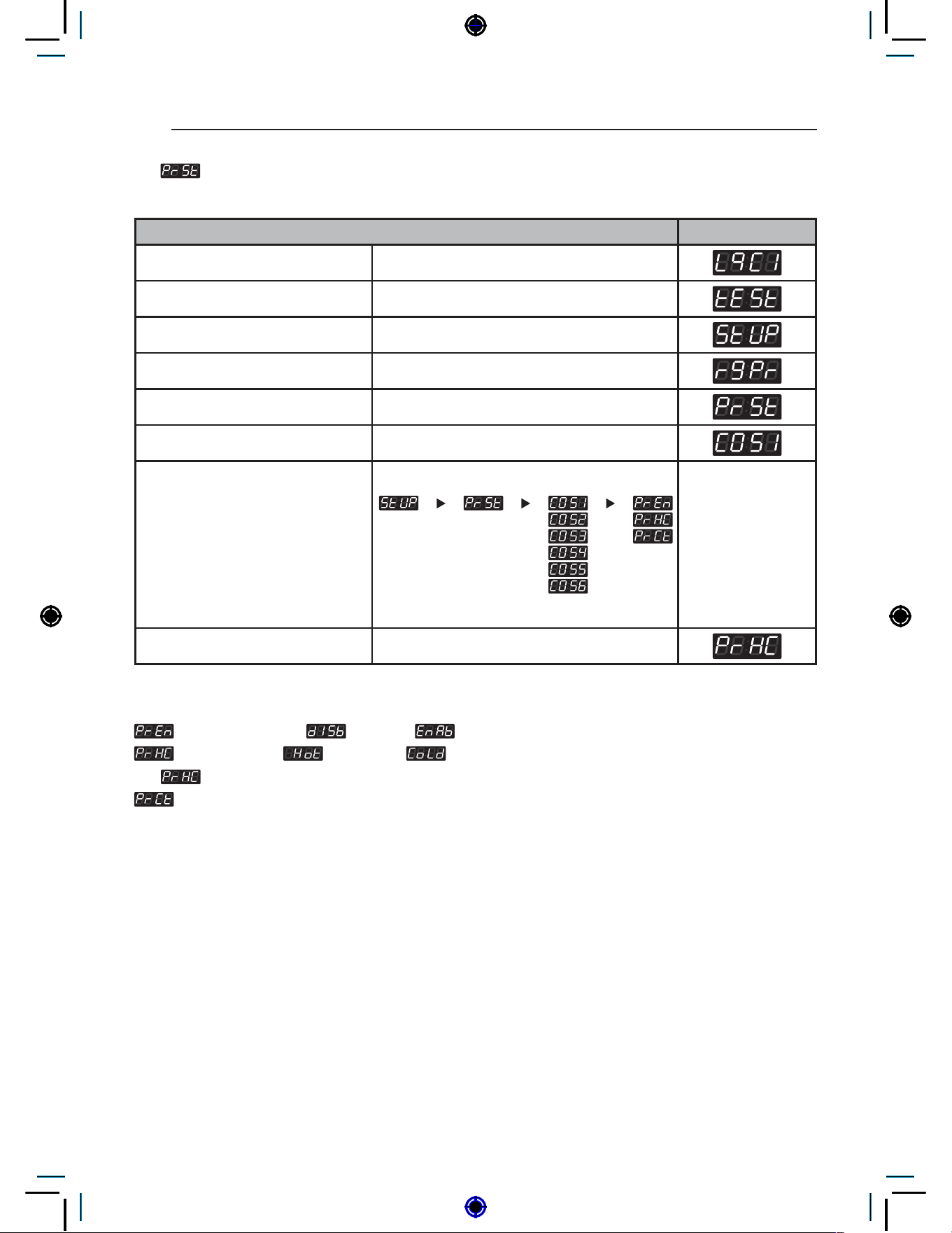
50
PROGRAMING MODE – SETUP MODE
11. Prewash Time Setup
Prewash Time Setup can be used to set the time for prewash.
Prewash Time Setup Display
Enter SVC mode
Press 1st button
Press 2nd button
Press start button
Press 2nd button or 3rd button Until display shows
Press start button
Select the setting you want
Button functions:
Start button = Select
1st button = Go back a step
2nd button = Move up or
increase value
3rd button = Move down or
decrease value
Press Start to set option The next menu setting will be displayed.
NOTE
: Prewash available( : disable / : enable)
: Prewash valve( : Hot vavle / : cold valve)
−
is used only on single type model.
: Prewash time(Range : 4~8)
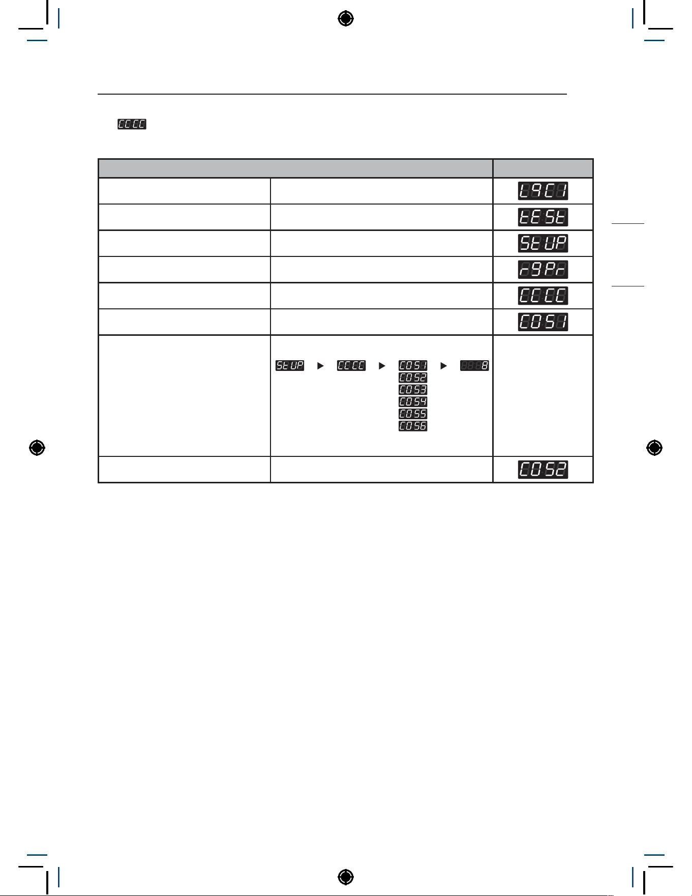
51
PROGRAMING MODE – SETUP MODE
NON HEATER
12. Wash Time Setup
Wash Time Setup can be used to set the duration of the wash process.
Wash Time Setup Display
Enter SVC mode
Press 1st button
Press 2nd button
Press start button
Press 2nd button or 3rd button Until display shows
Press start button
Select the setting you want
Button functions:
Start button = Select
1st button = Go back a step
2nd button = Move up or
increase value
3rd button = Move down or
decrease value
Press Start to set time The next course setting will be displayed.
NOTE
• Range : 5~15 min
• Increments : 1
• COS1 : Hot
• COS2 : Warm
• COS3 : Cold
• COS4 : Delicates
• COS5, COS6 : Heater model only

52
PROGRAMING MODE – SETUP MODE
13. Number of Rinses per Cycle Setup
Number of Rinses per Cycle Setup can be used to set number of rinses for one cycle.
Number of Rinses per Cycle Setup Display
Enter SVC mode
Press 1st button
Press 2nd button
Press start button
Press 2nd button or 3rd button Until display shows
Press start button
Select the setting you want
Button functions:
Start button = Select
1st button = Go back a step
2nd button = Move up or
increase value
3rd button = Move down or
decrease value
Press Start to set the number of
cycles
The next course setting will be displayed.
NOTE
• Range : 1~5
• Increments : 1
• COS1 : Hot
• COS2 : Warm
• COS3 : Cold
• COS4 : Delicates
• COS5, COS6 : Heater model only
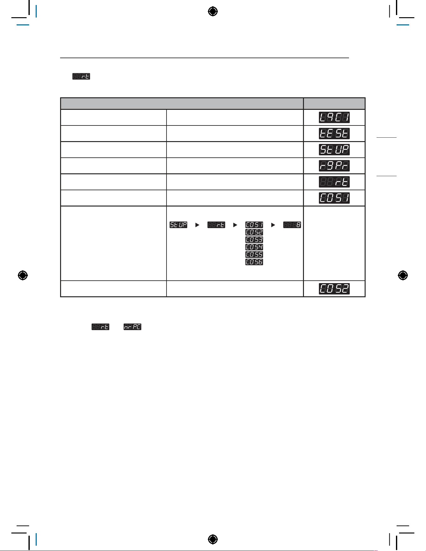
53
PROGRAMING MODE – SETUP MODE
NON HEATER
14. Rinse Time Setup
Rinse Time Setup can be used to set the duration of one rinse.
Rinse Time Setup Display
Enter SVC mode
Press 1st button
Press 2nd button
Press start button
Press 2nd button or 3rd button Until display shows
Press start button
Select the setting you want
Button functions:
Start button = Select
1st button = Go back a step
2nd button = Move up or
increase value
3rd button = Move down or
decrease value
Press Start to set time The next course setting will be displayed.
NOTE
• Multiple
and to calculate total rinse process time
• Range : 8~16 min
• Increments : 1
• COS1 : Hot
• COS2 : Warm
• COS3 : Cold
• COS4 : Delicates
• COS5, COS6 : Heater model only

54
PROGRAMING MODE – SETUP MODE
15. Top Spin Speed Setup
Top Spin Speed Setup can be used to set the maximum RPM for the spin process.
Top Spin Speed Setup Display
Enter SVC mode
Press 1st button
Press 2nd button
Press start button
Press 2nd button or 3rd button Until display shows
Press start button
Select the setting you want
Button functions:
Start button = Select
1st button = Go back a step
2nd button = Move up or
increase value
3rd button = Move down or
decrease value
Press Start to set the number The next course setting will be displayed.
NOTE
• Range : 0~6
• Increments : 1
• COS1 : Hot
• COS2 : Warm
• COS3 : Cold
• COS4 : Delicates
• COS5, COS6 : Heater model only
0 : 1200RPM
1 : 1000 RPM
2 : 900 RPM
3 : 800 RPM
4 : 700 RPM
5 : 600 RPM
6 : 500 RPM
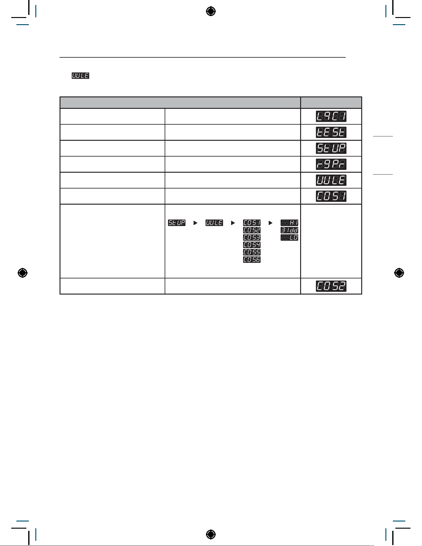
55
PROGRAMING MODE – SETUP MODE
NON HEATER
16. Water Level Setup
Water Level Setup can be used to set the water supply level.
Water Level Setup Display
Enter SVC mode
Press 1st button
Press 2nd button
Press start button
Press 2nd button or 3rd button Until display shows
Press start button
Select the setting you want
Button functions:
Start button = Select
1st button = Go back a step
2nd button = Move up or
increase value
3rd button = Move down or
decrease value
Press Start to set the level The next course setting will be displayed.
NOTE
• COS1 : Hot
• COS2 : Warm
• COS3 : Cold
• COS4 : Delicates
• COS5, COS6 : Heater model only
• Water level frequency
• High : 23.0 KHz
• Middle : 23.5 KHz
• Low : 23.8 KHz

56
PROGRAMING MODE – SETUP MODE
17. Rinse Spin Setup
Rinse Spin Setup can be used to enable/disable spin during rinse cycle.
Rinse Spin Setup Display
Enter SVC mode
Press 1st button
Press 2nd button
Press start button
Press 2nd button or 3rd button Until display shows
Press start button
Select the setting you want
Button functions:
Start button = Select
1st button = Go back a step
2nd button = Move up or
increase value
3rd button = Move down or
decrease value
Press Start to enable or disable The next course setting will be displayed.
NOTE
: 1st rinse spin skip
: 2nd rinse spin skip
: 3rd rinse spin skip
: 4th rinse spin skip
: 5th, 6th rinse spin skip
6th rinse spin refers to Add super wash rinse.
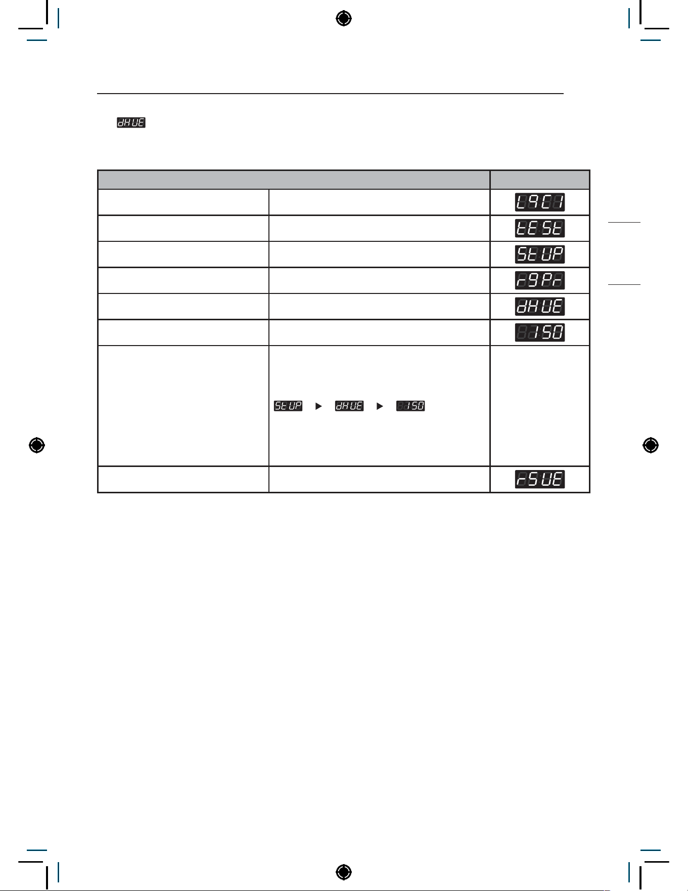
57
PROGRAMING MODE – SETUP MODE
NON HEATER
18. Drop Count Setup
Drop Count Setup can be used to set the number of drop counts. Drops occur while the machine
checks for balancing of the load as the cycle enters higher RPM.
Drop Count Setup Display
Enter SVC mode
Press 1st button
Press 2nd button
Press start button
Press 2nd button or 3rd button Until display shows
Press start button
Select the setting you want
Button functions:
Start button = Select
1st button = Go back a step
2nd button = Move up or
increase value
3rd button = Move down or
decrease value
Press Start to set the number The next menu setting will be displayed.
NOTE
• Drop counts 25~145: After dropping the selected amount of counts, UE will not occur. The cycle will
end immediately or after spinning at a low RPM.
• Drop counts 150: After dropping the selected amount of counts, UE will occur. The cycle will end after
shut down time. Refer to How to set shut down time after UE.

58
PROGRAMING MODE – SETUP MODE
19. Rinse Spin Drop Count Setup
Rinse Spin Drop Count Setup can be used to set the drop count for each rinse spin. Drops occur
while the machine checks for balancing of the load as the cycle enters higher RPM.
Rinse Spin Drop Count Setup Display
Enter SVC mode
Press 1st button
Press 2nd button
Press start button
Press 2nd button or 3rd button Until display shows
Press start button
Select the setting you want
Button functions:
Start button = Select
1st button = Go back a step
2nd button = Move up or
increase value
3rd button = Move down or
decrease value
Press Start to set the number The next menu setting will be displayed.
NOTE
• Range : 5~15
• Increments : 1
• If unable to reach target RPM within set number of drops, cycle will continue to next step.

59
PROGRAMING MODE – SETUP MODE
NON HEATER
20. UE Shutdown Setup
UE Shutdown Setup can be used to set the time to display UE until the cycle ends.
UE Shutdown Setup Display
Enter SVC mode
Press 1st button
Press 2nd button
Press start button
Press 2nd button or 3rd button Until display shows
Press start button
Select the setting you want
Button functions:
Start button = Select
1st button = Go back a step
2nd button = Move up or
increase value
3rd button = Move down or
decrease value
Press Start to set the time The next menu setting will be displayed.
NOTE
• Range : 0~10 min
• If
setting is disabled,
− 0 : UE will remain until user opens door, redistributes clothes, and starts up spin process again.
− 1~10 : Cycle will end after set time.
• If
setting is enabled,
− 0 : UE will remain until the “Start” button in selected.
− 1~10 : Washer returns to standby mode after the designated programmed time.
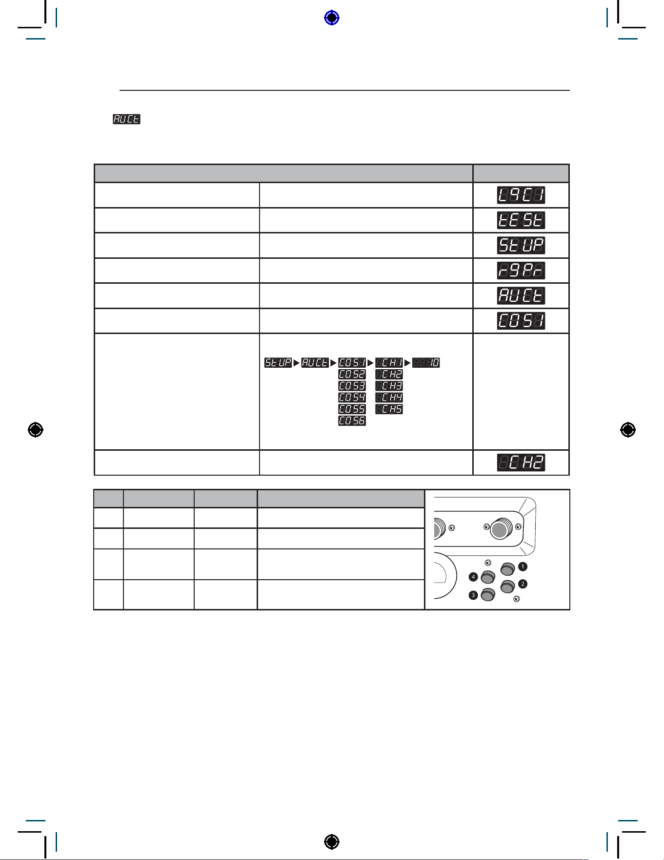
60
PROGRAMING MODE – SETUP MODE
21. Auto Dosing Pump Time Setup
Auto Dosing Pump Time Setup can be used to set the pump activation duration for each channel per
course.
Auto Dosing Pump Time Setup Display
Enter SVC mode
Press 1st button
Press 2nd button
Press start button
Press 2nd button or 3rd button Until display shows
Press start button
Select the setting you want
Button functions:
Start button = Select
1st button = Go back a step
2nd button = Move up or
increase value
3rd button = Move down or
decrease value
Press Start to set the time The next channel setting will be displayed.
CH Detergent Range (s) Input period
a
Pre-wash 0~20 Pre-wash phase
b
Main wash 0~20 Main wash phase
c
Bleach 0~10
Main wash (Remaining washing
time : 5 Minutes)
d
Softener 0~20 Final rinse phase

61
PROGRAMING MODE – SETUP MODE
NON HEATER
22. Coin 1 Value Setup
Coin 1 Value Setup can be used to set the value of each coin signal received.
Coin1 Value Setup Display
Enter SVC mode
Press 1st button
Press 2nd button
Press start button
Press 2nd button or 3rd button Until display shows
Press start button
Select the price you want
Button functions:
Start button = Select
1st button = Go back a step
2nd button = Move up or
increase value
3rd button = Move down or
decrease value
Press Start to set the price The next menu setting will be displayed.
NOTE
• Range : 0.1~10.00
• Increment : 0.1
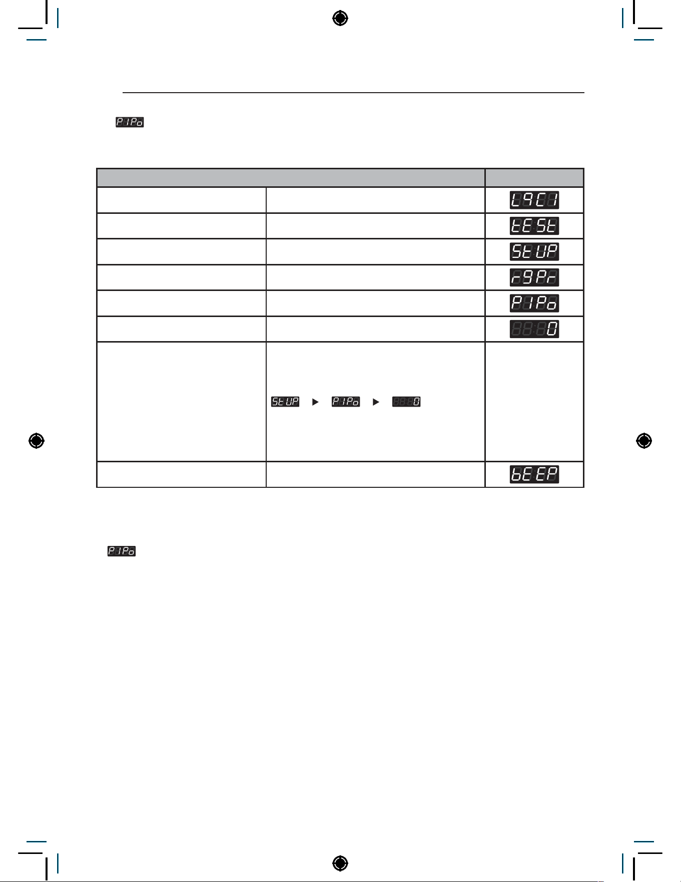
62
PROGRAMING MODE – SETUP MODE
23. Penny Increment Pricing Offset Setup
Penny Increment Pricing Offset Setup can be used to set additional cent increase when card is
used.
Penny Increment Pricing Offset Setup Display
Enter SVC mode
Press 1st button
Press 2nd button
Press start button
Press 2nd button or 3rd button Until display shows
Press start button
Select the price you want
Button functions:
Start button = Select
1st button = Go back a step
2nd button = Move up or
increase value
3rd button = Move down or
decrease value
Press Start to set the price The next menu setting will be displayed.
NOTE
• Range : 0~4
•
Penny increment pricing offset is available only in card type. It hasn’t affected the coin type’s
price setting.
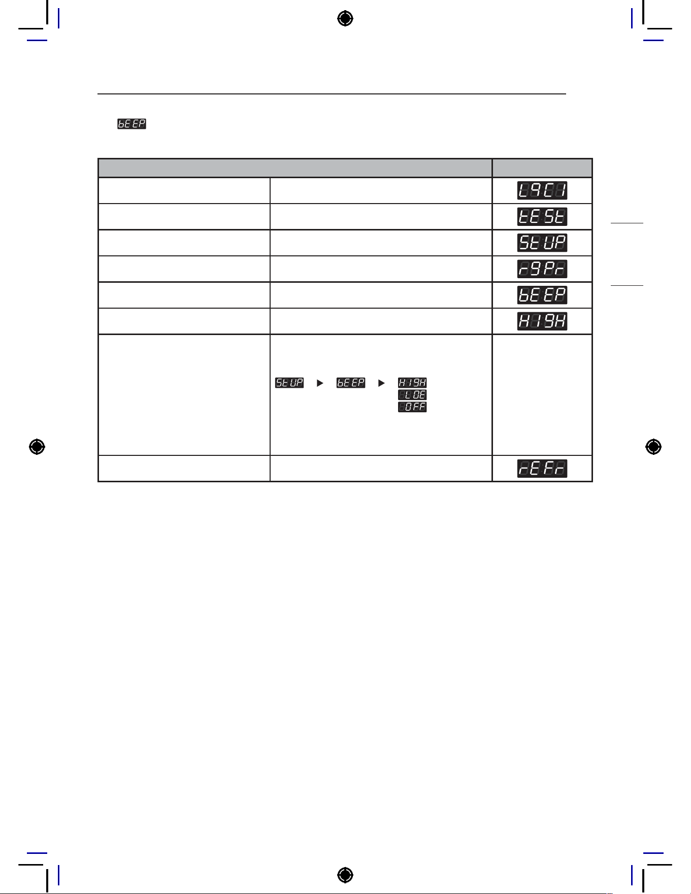
63
PROGRAMING MODE – SETUP MODE
NON HEATER
24. Beep Volume Setup
Beep Volume Setup can be used to set the sound level of the machine.
Beep Volume Setup Display
Enter SVC mode
Press 1st button
Press 2nd button
Press start button
Press 2nd button or 3rd button Until display shows
Press start button
Select the setting you want
Button functions:
Start button = Select
1st button = Go back a step
2nd button = Move up or
increase value
3rd button = Move down or
decrease value
Press Start to set the sound level The next menu setting will be displayed.
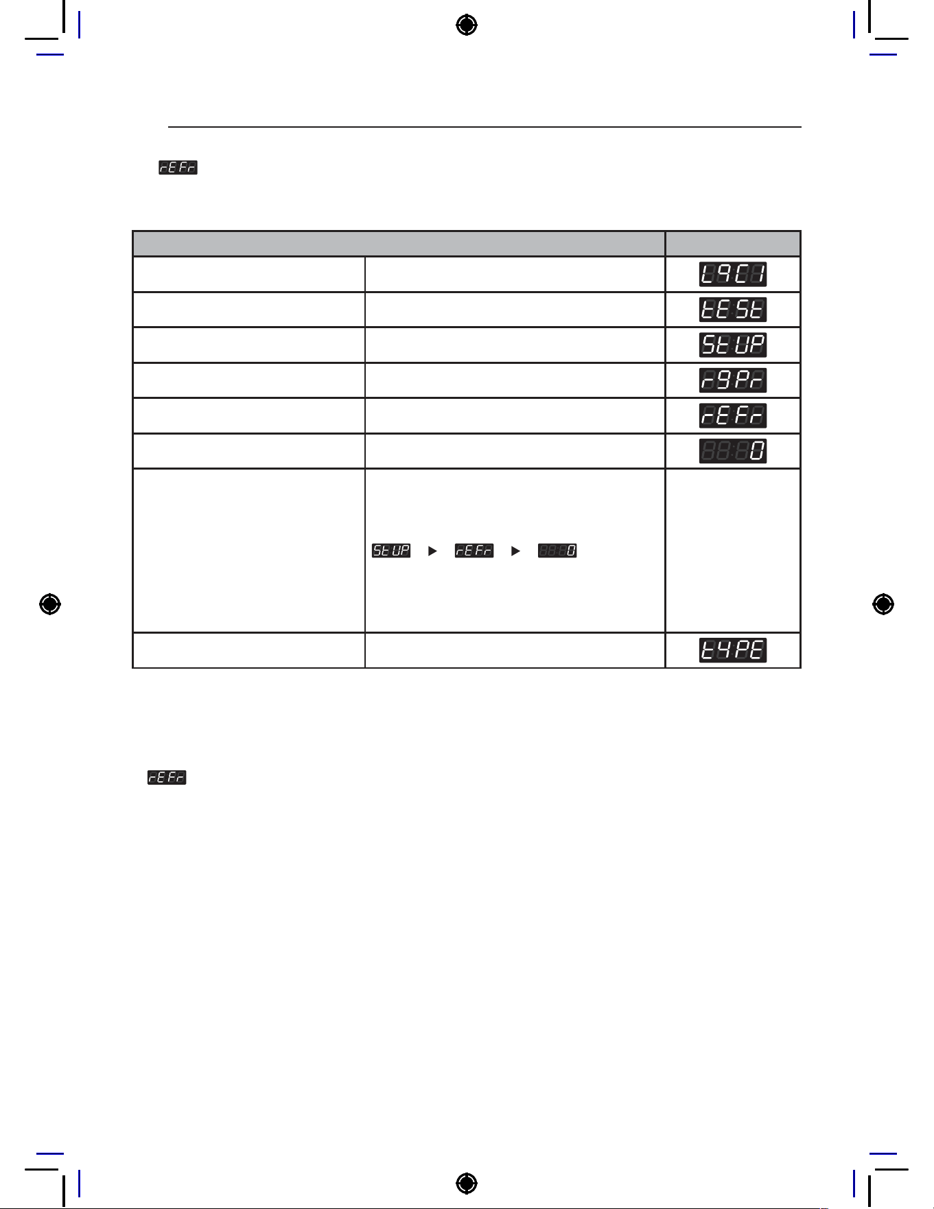
64
PROGRAMING MODE – SETUP MODE
25. Standby Return Time Setup
Standby Return Time Setup can be used to set how long the input payment is held until the machine
resets to standby mode.
Standby Return Time Setup Display
Enter SVC mode
Press 1st button
Press 2nd button
Press start button
Press 2nd button or 3rd button Until display shows
Press start button
Select the setting you want
Button functions:
Start button = Select
1st button = Go back a step
2nd button = Move up or
increase value
3rd button = Move down or
decrease value
Press Start to set the time The next menu setting will be displayed.
NOTE
• 0 : Holds input payment permanently.
• 1~180 : Holds input payment for selected amount of time, then returns to standby mode.
•
: Standby return time setup is available only in coin type.
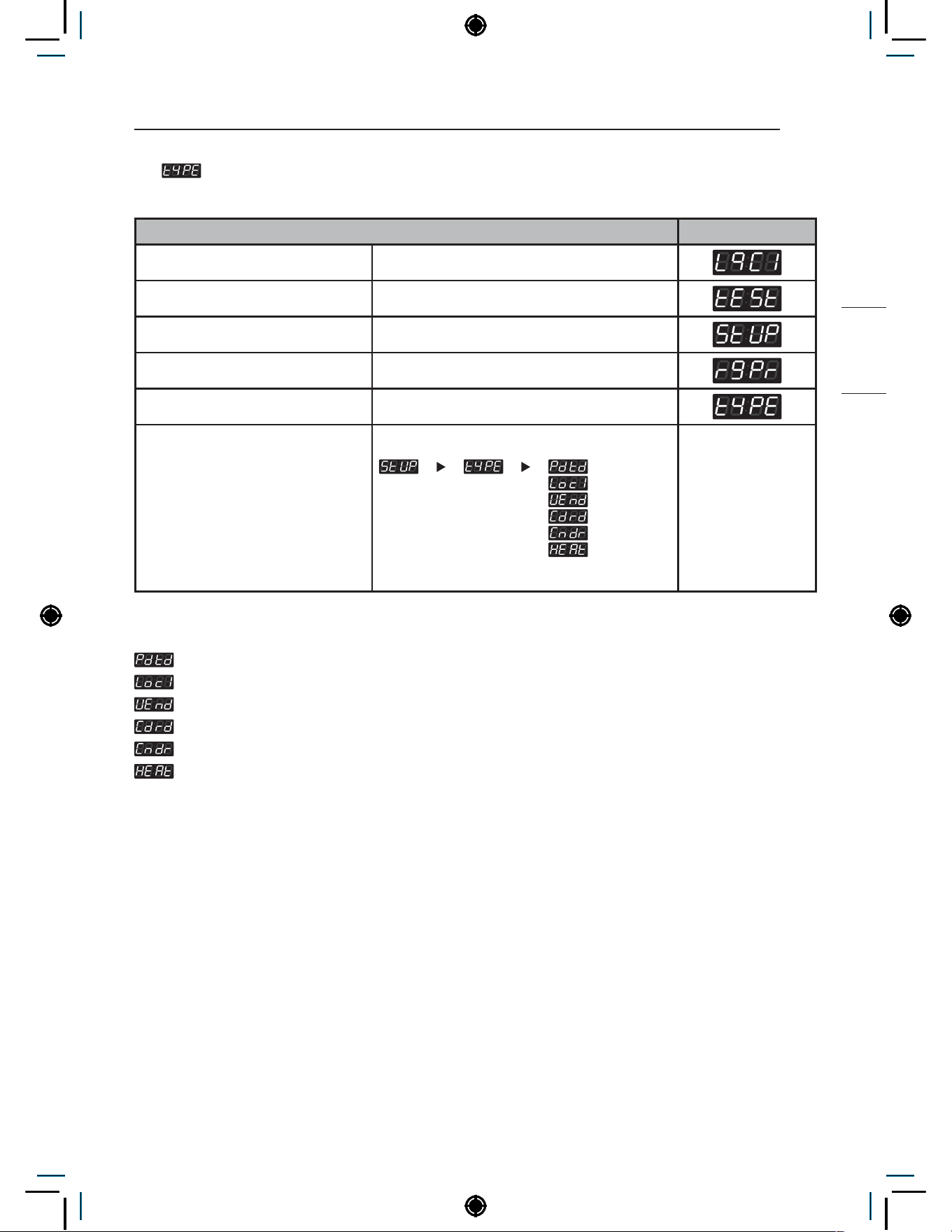
65
PROGRAMING MODE – SETUP MODE
NON HEATER
26. Type
Type can be used to set the machine’s various type settings.
Type Display
Enter SVC mode
Press 1st button
Press 2nd button
Press start button
Press 2nd button or 3rd button Until display shows
Select the setting you want
Button functions:
Start button = Select
1st button = Go back a step
2nd button = Move up or
increase value
3rd button = Move down or
decrease value
NOTE
: Product type
: Currency type
: Vend type
: Card reader type
: Coin meter type
: Heater type
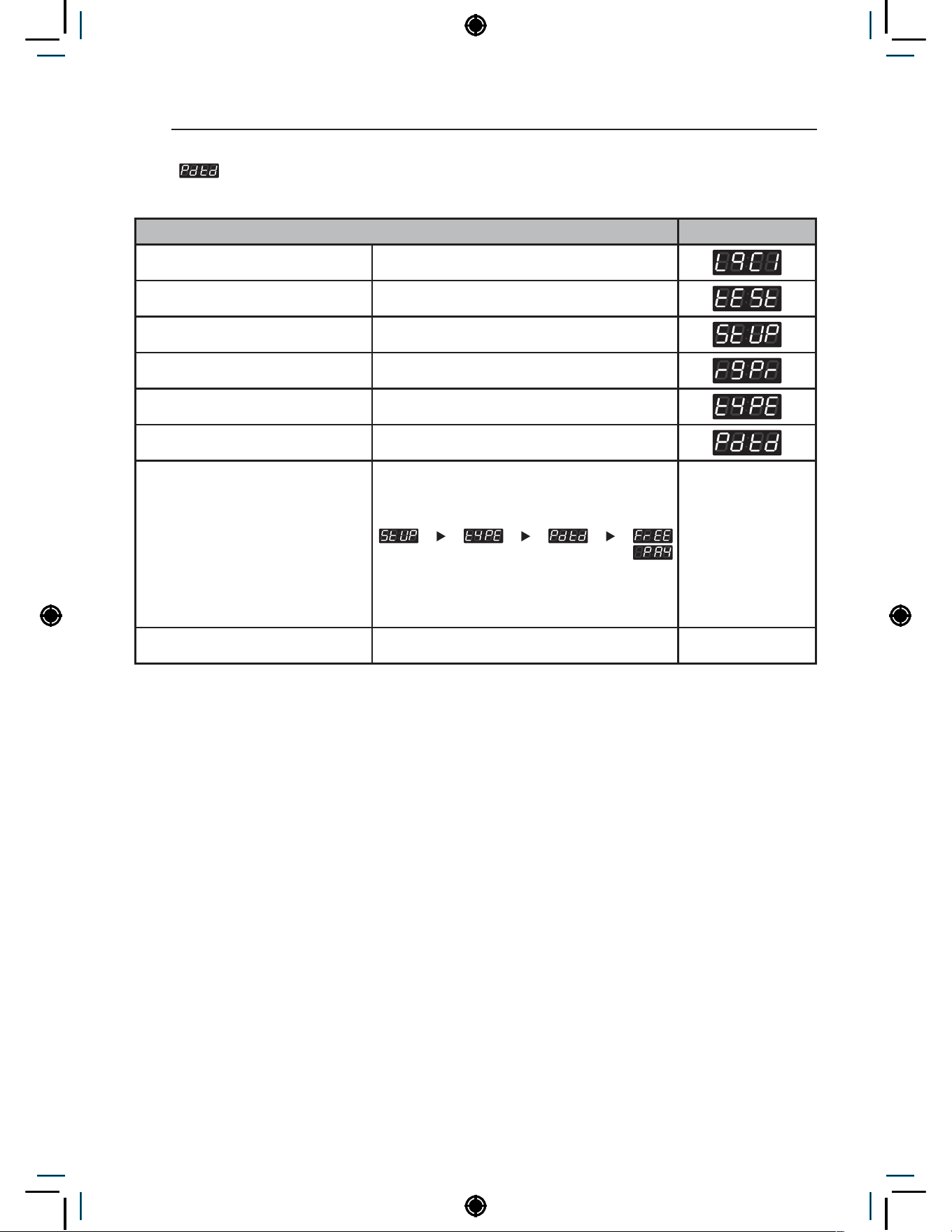
66
PROGRAMING MODE – SETUP MODE
26-1. Product Type Setup
Product Type Setup can be used to set the machine’s payment type (Pay or Free)
Product Type Setup Display
Enter SVC mode
Press 1st button
Press 2nd button
Press start button
Press 2nd button or 3rd button Until display shows
Press Start button
Select the setting you want
Button functions:
Start button = Select
1st button = Go back a step
2nd button = Move up or
increase value
3rd button = Move down or
decrease value
Press Start to set the type Display returns to standby mode.
NOTE
• PAY : Coin/Card
• FrEE : On Premise Laundry
• Issues may occur if certain large items are loaded after changing from Free type to Pay type.
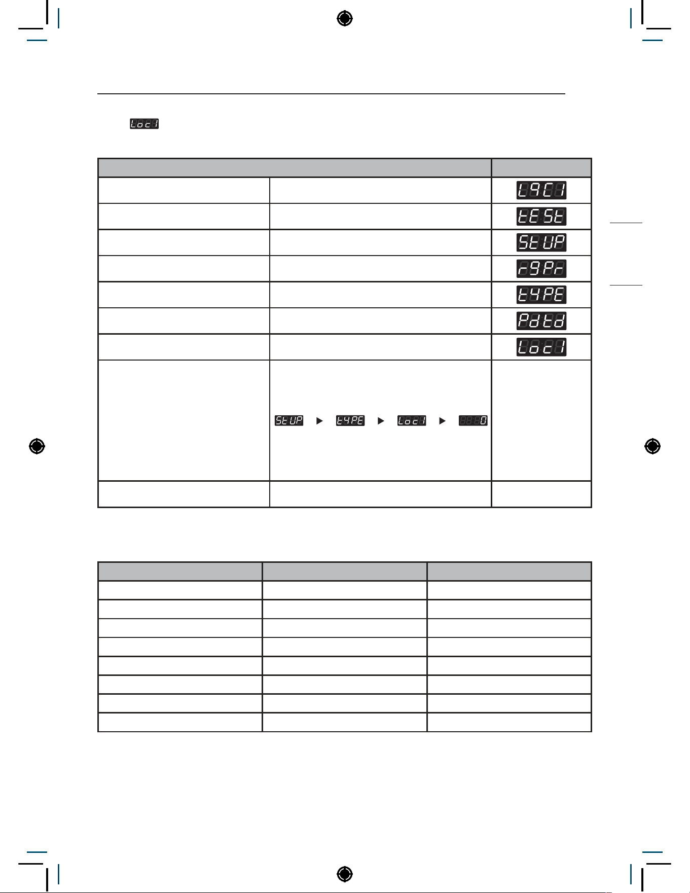
67
PROGRAMING MODE – SETUP MODE
NON HEATER
26-2. Currency Type Setup
Currency Type Setup can be used to set the country and its currency
Currency Type Setup Display
Enter SVC mode
Press 1st button
Press 2nd button
Press start button
Press 2nd button or 3rd button Until display shows
Press Start button
Press 2nd button or 3rd button Until display shows
Select the setting you want
Button functions:
Start button = Select
1st button = Go back a step
2nd button = Move up or
increase value
3rd button = Move down or
decrease value
Press Start to set the type Display returns to standby mode.
NOTE
Country (Loc1) Range Increments
England (0) 0~10.00 0.10
Australia (1) 0~10.00 1.00
USA (2) 0~9.95 0.05
China (3) 0~199 1
Korea (4) 0~9500 100
Japan (5) 0~9500 100
Canada (6) 0~9.95 0.05
Philippines (7) 0~995 5
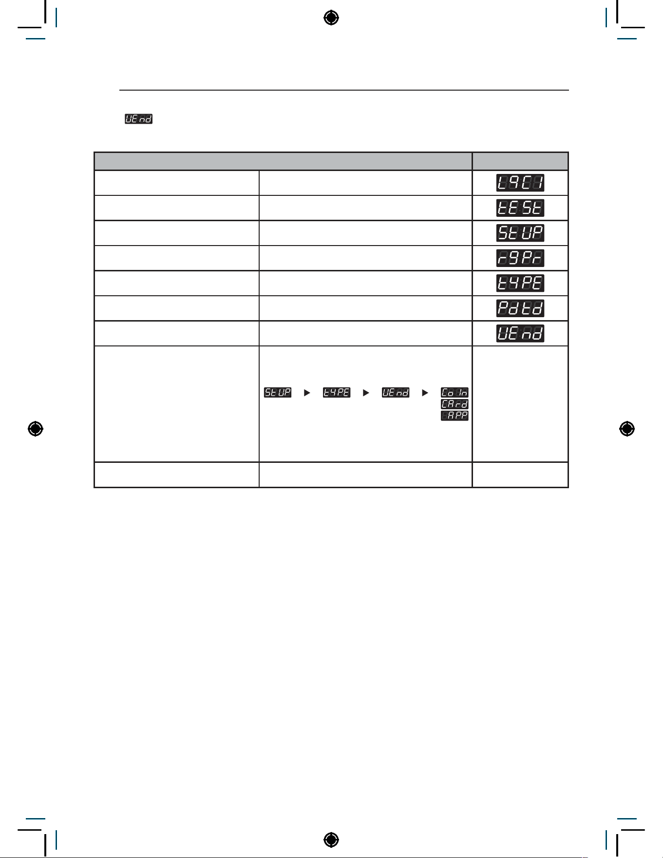
68
PROGRAMING MODE – SETUP MODE
26-3. Vend Type Setup
Vent Type Setup can be used to set the payment type (Coin/Card/Mobile pay).
Vend Type Setup Display
Enter SVC mode
Press 1st button
Press 2nd button
Press start button
Press 2nd button or 3rd button Until display shows
Press Start button
Press 2nd button or 3rd button Until display shows
Select the setting you want
Button functions:
Start button = Select
1st button = Go back a step
2nd button = Move up or
increase value
3rd button = Move down or
decrease value
Press Start to set the type Display returns to standby mode.
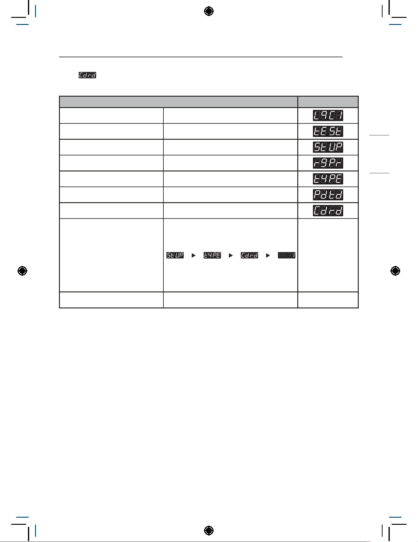
69
PROGRAMING MODE – SETUP MODE
NON HEATER
26-4. Card Reader Type Setup
Card Reader Type can be used to set the card reader company.
Card Reader Type Setup Display
Enter SVC mode
Press 1st button
Press 2nd button
Press start button
Press 2nd button or 3rd button Until display shows
Press Start button
Press 2nd button or 3rd button Until display shows
Select the setting you want
Button functions:
Start button = Select
1st button = Go back a step
2nd button = Move up or
increase value
3rd button = Move down or
decrease value
Press Start to set the type Display returns to standby mode.
NOTE
• 0 : Greenwald
• 1 : ESD
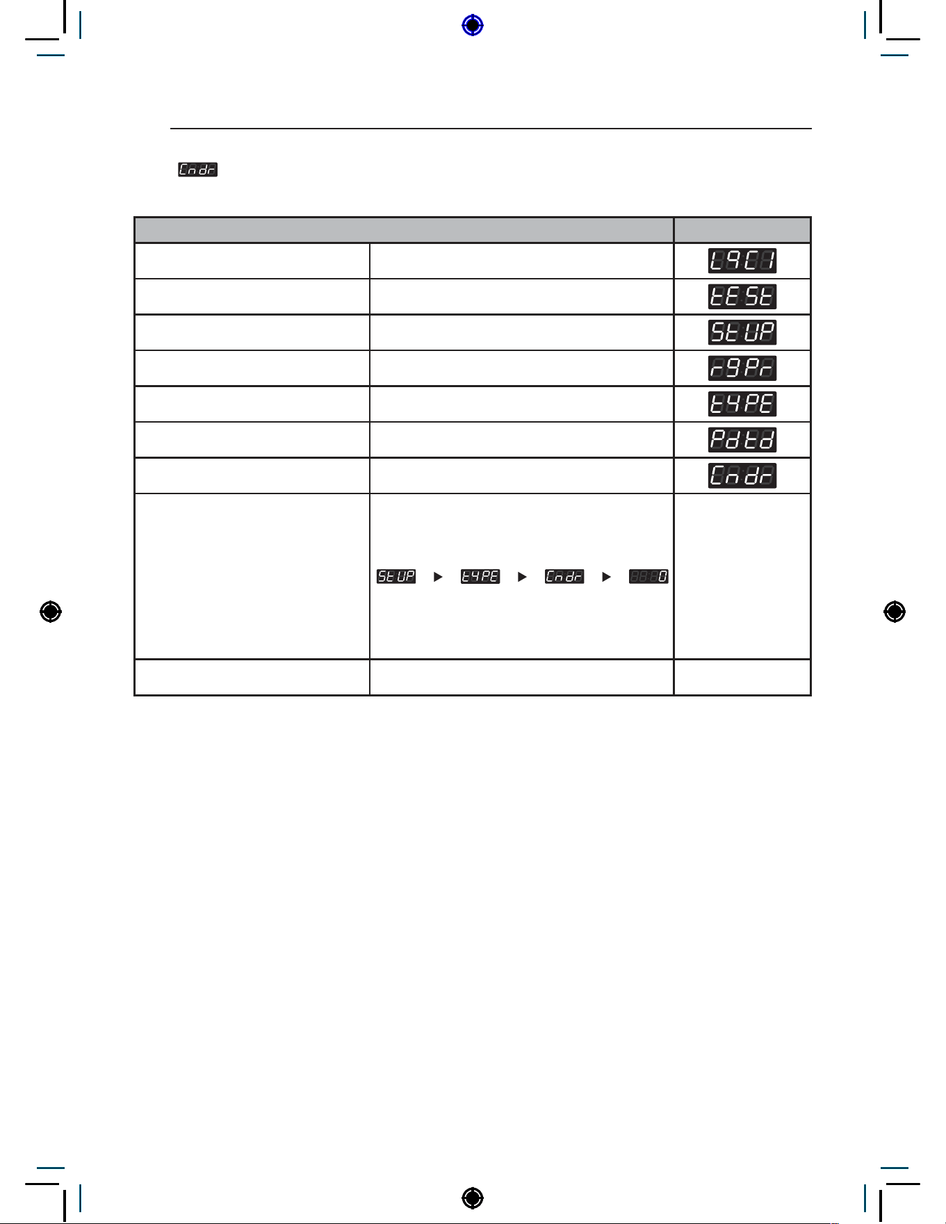
70
PROGRAMING MODE – SETUP MODE
26-5. Coin Drop Type Setup
Coin Drop Type can be used to set the coin pulse signal setting for coin drops.
Coin Drop Type Setup Display
Enter SVC mode
Press 1st button
Press 2nd button
Press start button
Press 2nd button or 3rd button Until display shows
Press Start button
Press 2nd button or 3rd button Until display shows
Select the setting you want
Button functions:
Start button = Select
1st button = Go back a step
2nd button = Move up or
increase value
3rd button = Move down or
decrease value
Press Start to set the type Display returns to standby mode.
NOTE
• Coin pulse
• 0 : 50ms : ESD, Greenwald, Munzprufer
• 1 : 100ms : Korea
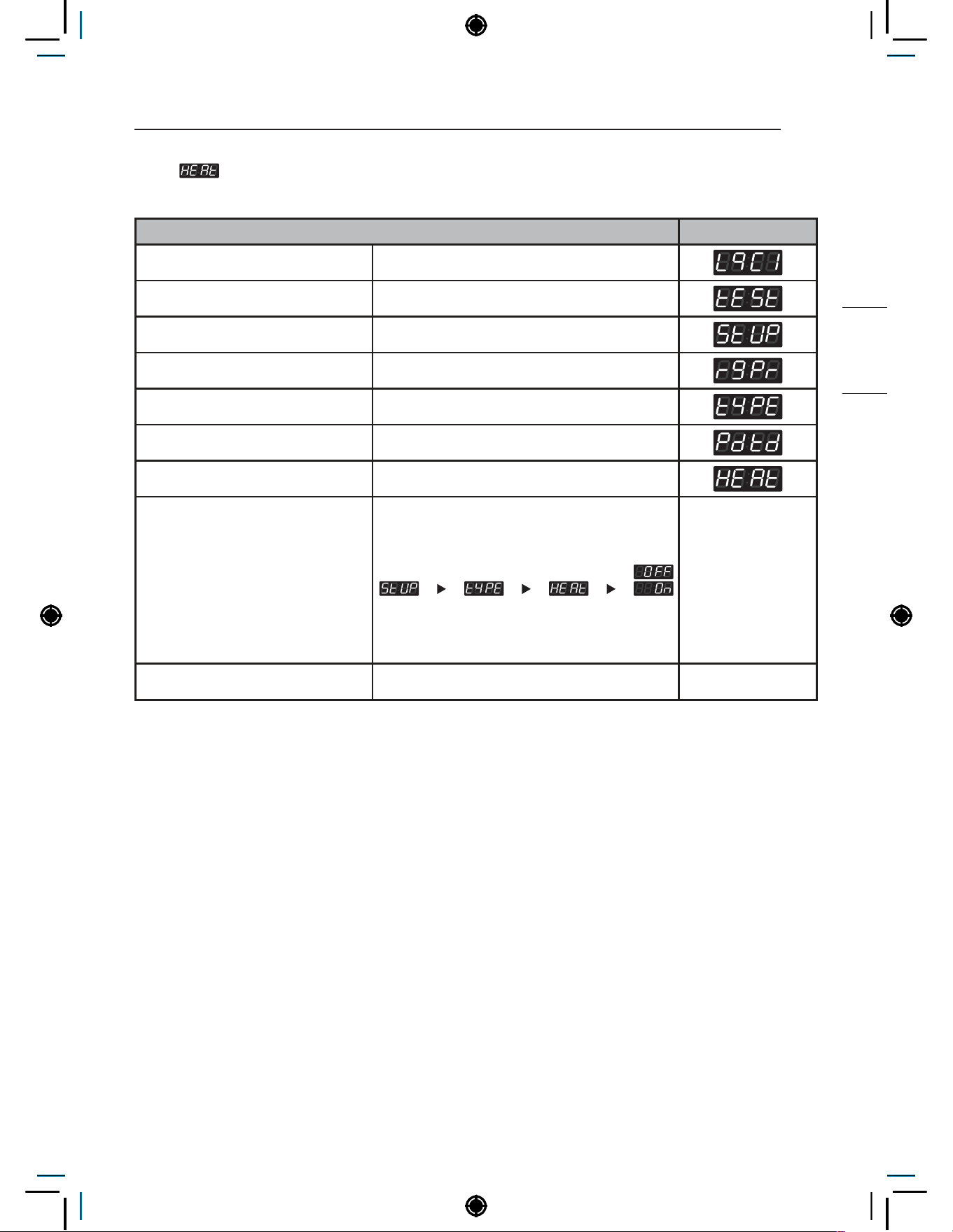
71
PROGRAMING MODE – SETUP MODE
NON HEATER
26-6. Heater type setup
Heater type setup can be used to set machine’s tool(heater/non heater).
Heater Type Setup Display
Enter SVC mode
Press 1st button
Press 2nd button
Press start button
Press 2nd button or 3rd button Until display shows
Press Start button
Press 2nd button or 3rd button Until display shows
Select the setting you want
Button functions:
Start button = Select
1st button = Go back a step
2nd button = Move up or
increase value
3rd button = Move down or
decrease value
Press Start to set the type Display returns to standby mode.
NOTE
• On : Heater
• OFF : Non heater

72
PROGRAMING MODE – SETUP MODE
27. Max Surpassed Cycle Time Setup
Cut off time is how long the machine can run after the display time has been reached. This feature
allows the adjustment of the cut off time between 1 and 15 minutes.
Max Surpassed Cycle Time Setup Display
Enter SVC mode
Press 1st button
Press 2nd button
Press start button
Press 2nd button or 3rd button Until display shows
Press Start button
Select the setting you want
Button functions:
Start button = Select
1st button = Go back a step
2nd button = Move up or
increase value
3rd button = Move down or
decrease value
Press Start to set the time. The next menu setting will be displayed.
NOTE
• Range : 1~15 min
• Increments : 1
• The washer will try and complete the entire cycle in the allotted display time. However, in the case of
an off balance load or too much soap, the washer will use the extra cut off time to balance or remove
excess soap before ending the cycle.
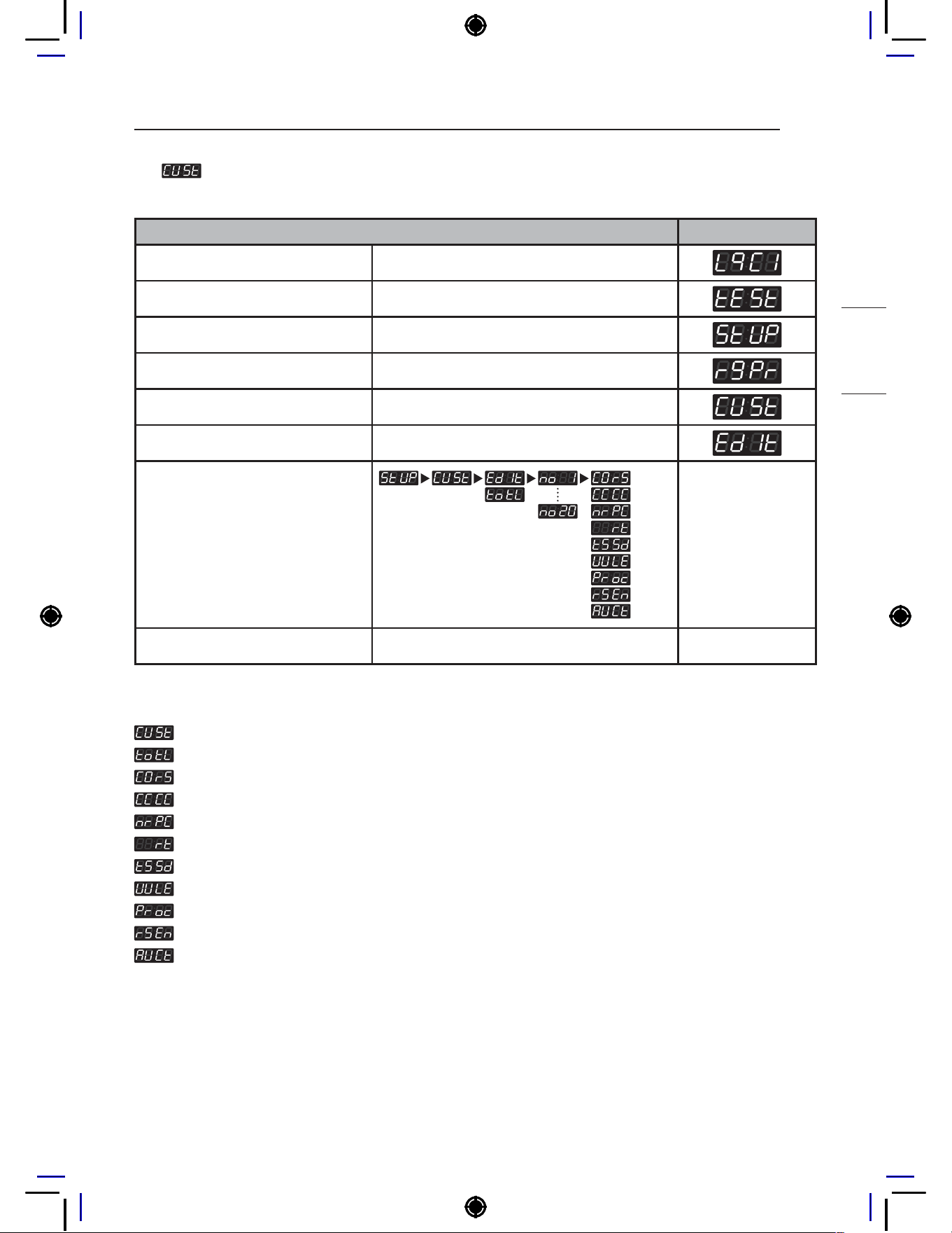
73
PROGRAMING MODE – SETUP MODE
NON HEATER
28. Custom Program Setup
Custom Program can be used to create up to 20 different customized courses.
Custom Program Setup Display
Enter SVC mode
Press 1st button
Press 2nd button
Press start button
Press 2nd button or 3rd button Until display shows
Press Start button
Select the setting you want
Button functions:
Start button = Select
1st button = Go back a step
2nd button = Move up or
increase value
3rd button = Move down or
decrease value
Press Start to set
NOTE
: only available in FrEE type.
: Total number of custom courses (1~20)
: Select base course
: Wash Time
: Number of Rinse per Cycle
: Rinse Time
: Top Spin Speed
: Water Level
: Rinse Spin Only, Spin Only
: Rinse Spin
: Auto Dosing Pump Time
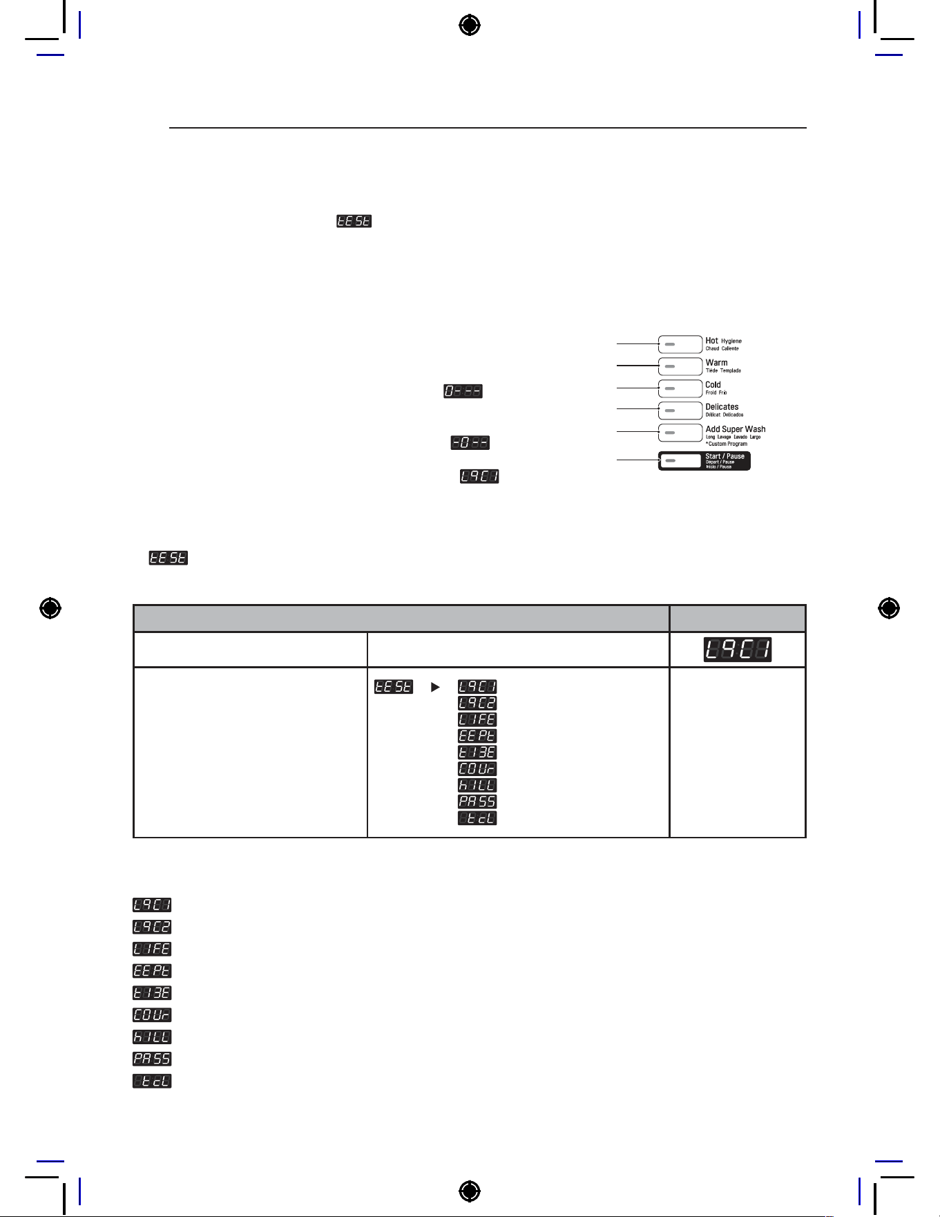
74
Programing Mode – Test Mode
Programing Mode – Test Mode
Diagnostic tests:
(display)
This program has been added for testing the washer and detecting errors.
How to enter Programming mode:
• Coin type – Turn on/off the toggle switch.
• Card type – Insert the service card.
• All types –
1
Press the 1st & 3rd button at the same time.
2
Press the 2nd & 3rd buttons to toggle numbers. Then,
press the 4th button to move to the next digit.
3
Press the Start button to finish password input.
* Default Password : 3000
<Control Panel Button>
1st
2nd
3rd
4th
5th
Start
1. Test
Test features can be used to check and change various machine settings.
Test mode Display
Enter SVC mode
Select the feature you want
Button functions:
Start button = Select
1st button = Go back a step
2nd button = Move up or
increase value
3rd button = Move down or
decrease value
NOTE
: Diagnostic Test 1
: Factory Use (Do not Use)
: Factory Use (Do not Use)
: Factory Reset
: Time Setting
: Courtesy Cycle
: Cycle Kill
: Password Setup
: Tub Clean Course
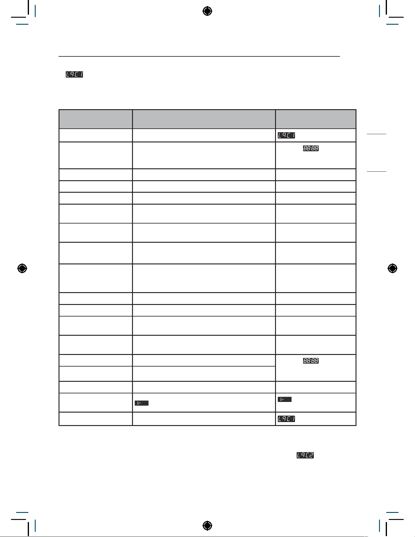
75
Programing Mode – Test Mode
NON HEATER
2. Diagnostic Test
Diagnostic Test can be used to check functionality of various machine parts.
Press Start to move through the check points.
Number of times the
Start button is pressed
Check point Display
0 Enter SVC mode
1 Turns on all lamps and locks the door
Displays
, 1U:XX,
1g:XX, 10:XX, 1C:XX
alternately (Version)
2 Tumble clockwise rpm (40~50)
3 Low speed spin rpm (600
4 High speed spin rpm (1200)
5 Inlet valve for main water turns on
Water level frequency
(255~)
6 Inlet valve for hot water turns on
Water level frequency
(255~)
7
Inlet valve for atomizing turns on (Single model)
Inlet valve for softener turns on (Stack model)
Water level frequency
(255~)
8
Inlet valve for bleach turns on (Single model)
Inlet valve for atomizing/bleach turns on (Stack
model)
Water level frequency
(255~)
9 Tumble counter clockwise rpm (40~50)
10 Heater turns on Displays water temperature
11 Circulation pump turns on
Water level frequency
(255~)
12 Drain pump turns on
Water level frequency
(255~)
13 All lamps turn on
Displays
, 1U:XX,
1g:XX, 10:XX, 1C:XX
alternately (Version)
14 Button check
15 High speed spin rpm (1200)
16
PDA signal check
this function is not
applied in this machine
17
NOTE
• Make sure the drum is empty when diagnostic test is being performed. Do not use
.
• RPM notation is displayed except for the last number when it is more than a hundred.
(i.e. 1200 rpm is displayed as 120)

76
Programing Mode – Test Mode
3. Factory Reset
Factory Reset is used to reset the machine to default settings.
Factory Reset Display
Enter SVC mode
Press 2nd button or 3rd button Until display shows
Press Start button
Press 2nd button Until display shows
Press Start button
NOTE
• All settings return to default.
• Wash time : 8 minutes
• Rinse cycle : Twice
• Top spin speed : 800 rpm
• Add Super Wash : 3 minutes extra wash and one extra rinse
• Price setting varies by country
• After Factory Reset, set your country from
mode.
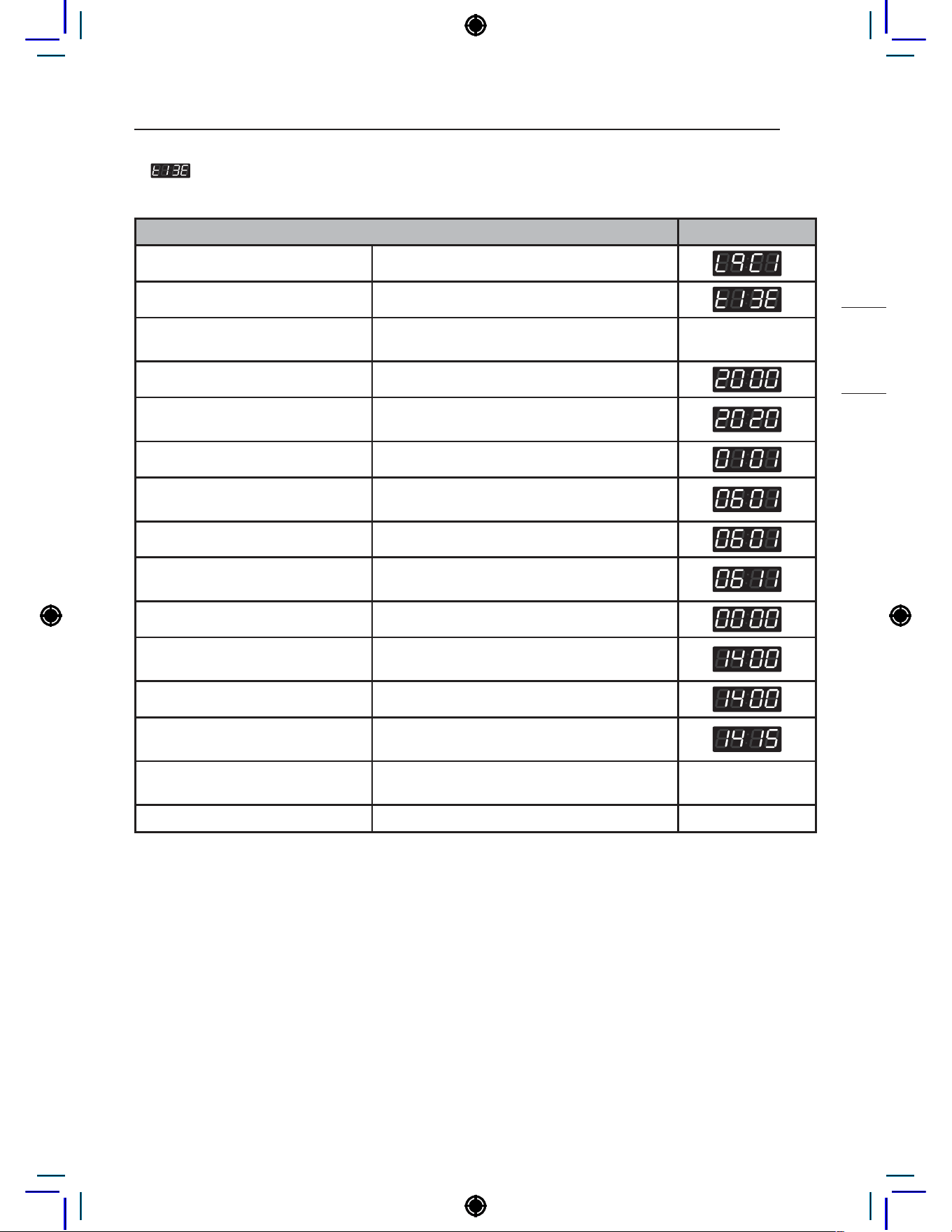
77
Programing Mode – Test Mode
NON HEATER
4. Time Setup
Time Setup can be used to set the current year, month, day, hour, and minute.
Time Setup Display
Enter SVC mode
Press 2nd button or 3rd button Until display shows
Press Start button
Display shows you 2000(Year) → 0101(Month/
Date) → Sat(Day) → 0000(Time(24hr))
Press Start button
Press 2nd button or 3rd button
Until display shows the year you want (i.e.
2020)
Press Start button
Press 2nd button or 3rd button
Until display shows the month you want in the
left two digits (i.e. June = 0601)
Press Start button
Press 2nd button or 3rd button
Until display shows the day you want in the
right two digits (i.e. June 11th = 0611)
Press Start button
Press 2nd button or 3rd button
Until display shows the hour you want (i.e.
2:00 PM = 1400)
Press Start button
Press 2nd button or 3rd button
Until displays shows the minute you want (i.e.
2:15 PM = 1415)
Press Start button
Display shows you 2000(Year) → 0101(Month/
Date) → Sat(Day) → 0000(Time(24hr))
Press 1st button Until display returns to standby mode
NOTE
• Time is displayed in military time format.
• Time Setup must be set to use Special Day Price feature.
• When the machine is powered off, Time Setup is reset to default.
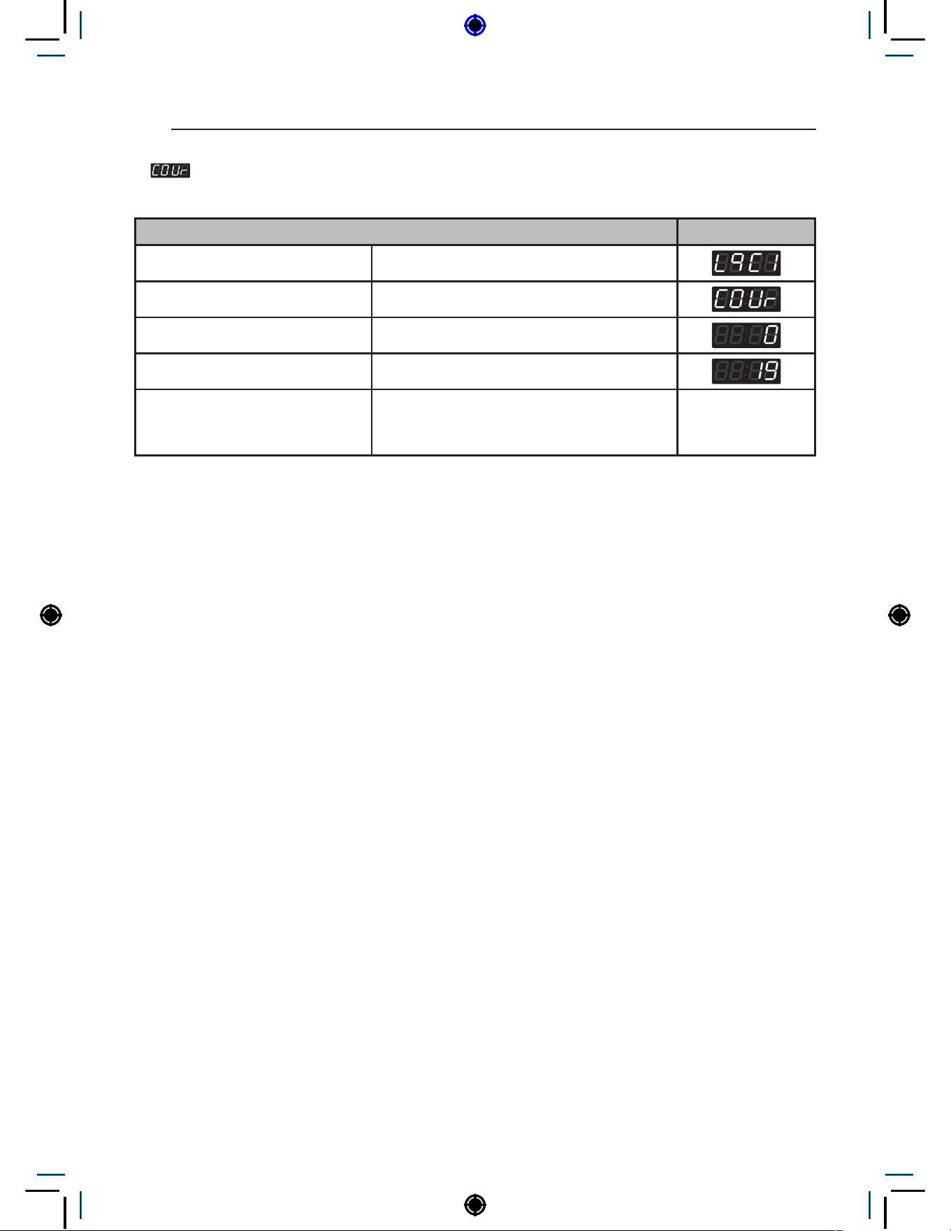
78
Programing Mode – Test Mode
5. Courtesy Cycle
Courtesy Cycle is a free cycle given to customers for Pay Type machines.
Courtesy Cycle Display
Enter SVC mode
Press 2nd button or 3rd button Until display shows
Press Start button
Press 2nd button Until display shows
Press Start button
Machine is ready to use.
User can choose desired course and press
Start.
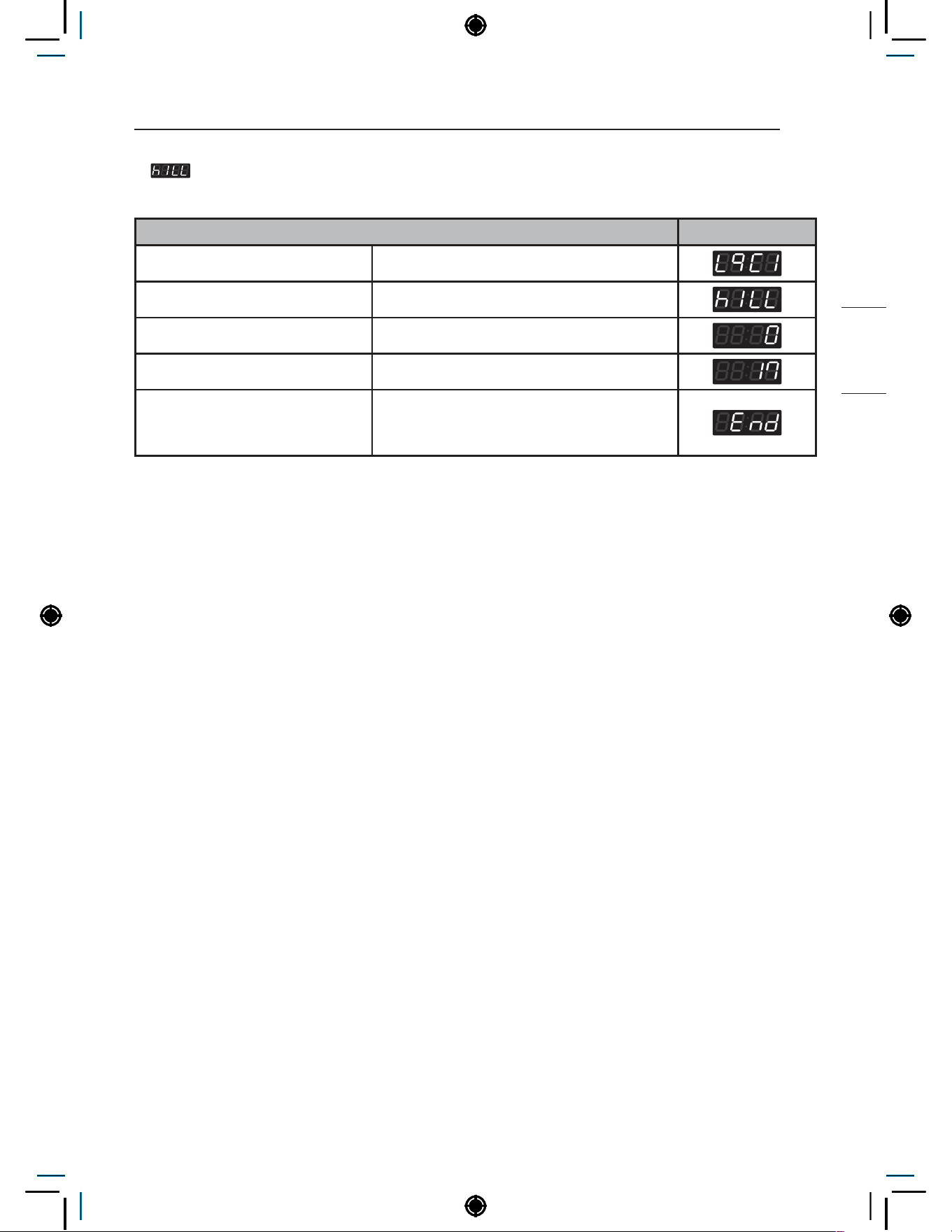
79
Programing Mode – Test Mode
NON HEATER
6. Kill Cycle
Kill Cycle is used to end the currently operating cycle.
Cycle Kill Display
Enter SVC mode
Press 2nd button or 3rd button Until display shows
Press Start button
Press 2nd button Until display shows
Press Start button
Machine is ready to use.
User can choose desired course and press
Start.
NOTE
• Only works for machine that is currently operating.
• Cycle can be ended with Cycle Kill Card for Card Type machines.
• Easy entry : Press and hold the start button for at least 3 seconds.
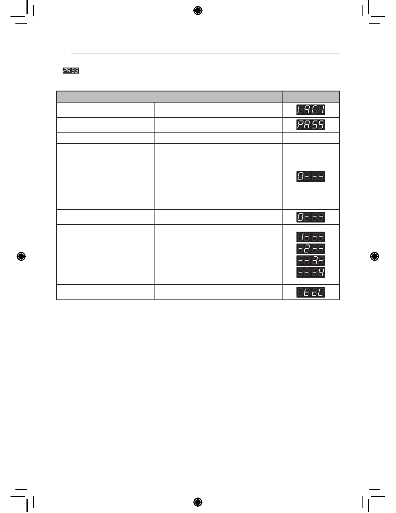
80
Programing Mode – Test Mode
7. Password Setup
Password Setup can be used to change the password to enter Service mode.
Password Setup Display
Enter SVC mode
Press 2nd button or 3rd button Until display shows
Press Start button
Button functions: Start button =
Select
1st button = Go back a step
2nd button = Move up or
increase value
3rd button = Move down or
decrease value
Input current password
Default Password : 3000
1
Press the 2nd & 3rd buttons to toggle
numbers.
2
Press the 4th button to move to the next
digit.
Press Start button
Button functions: Start button =
Select
1st button = Go back a step
2nd button = Move up or
increase value
3rd button = Move down or
decrease value
Input new password (i.e. 1234)
1
Press the 2nd & 3rd buttons to toggle
numbers.
2
Press the 4th button to move to the next
digit.
Press Start button New password is set
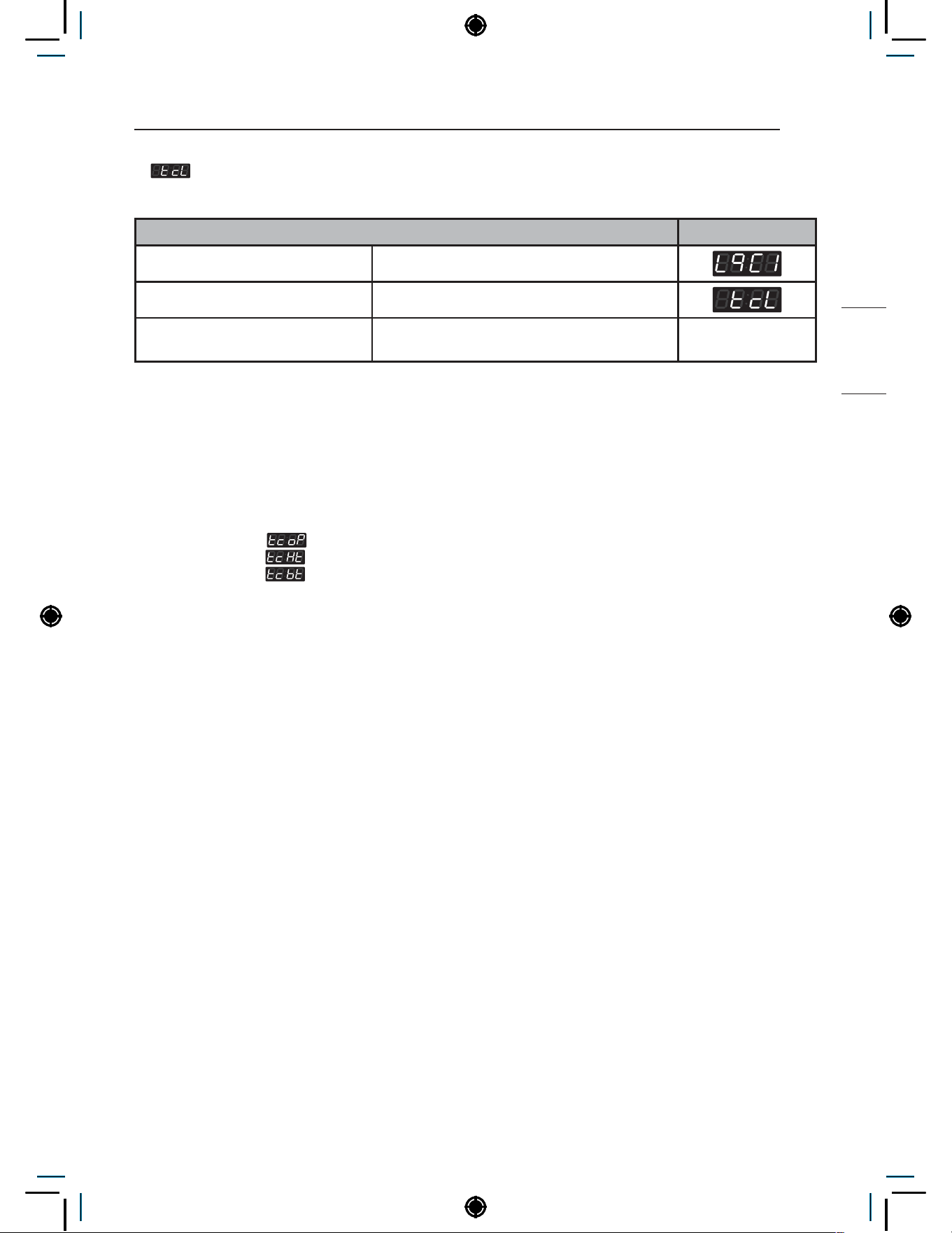
81
Programing Mode – Test Mode
NON HEATER
8. Tub Clean Course
Tub Clean Course is used to clean the drum.
Tub Clean Course Display
Enter SVC mode
Press 2nd button or 3rd button Until display shows
Press Start button
Display shows remaining time and starts the
Tub Clean Course.
NOTE
• Machine goes back to standby mode after Tub Clean Course is completed.
• Easy Entry : Press and hold the 1st button and 2nd button for at least 3 seconds.
• Display shows the default number of Tub Clean cycles to run. (Range : 1~3)
• Never load laundry when using Tub Clean Course. Laundry may be damaged or become contaminated.
• Tub Clean Course should be used every 50 cycles.
• Related functions
: Tub Clean Load Detection Setup
: Tub Clean Heater Setup
: Tub Clean Shortcut Button Setup
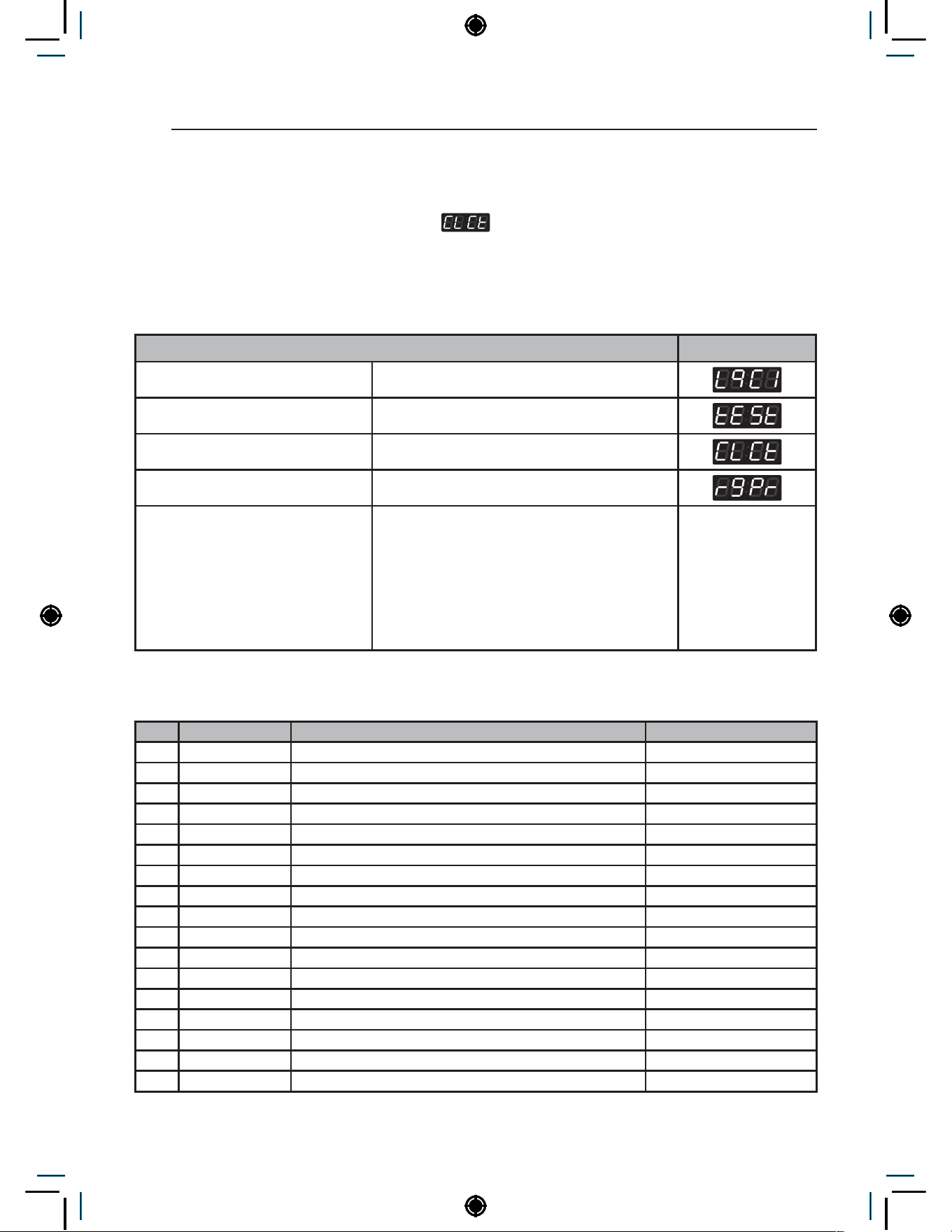
82
Programing Mode – Collect Mode
Programing Mode – Collect Mode
Collect information data :
(display)
The washer collects the usage data so that the owner can check various information like number of
various cycles used, how many times card or coins used, etc.
Collect Mode
Collect Mode Display
Enter SVC mode
Press 1st button
Press 2nd button or 3rd button Until display shows
Press Start button
Select the feature you want Start
button = Select
1st button = Go back a step
2nd button = Move up or
increase value
3rd button = Move down or
decrease value
Refer to the follow Collect Mode Data List
Collect Mode Data lists
No. Abbreviation Meaning Description
1 rgPr Regular Price (Default Price)
2 rgP1 Regular COS1 Price
3 rgP2 Regular COS2 Price
4 rgP3 Regular COS3 Price
5 rgP4 Regular COS4 Price
6 rgP5 Regular COS5 Price (for Heater)
7 rgP6 Regular COS6 Price (for Heater)
8 ItrC Interval Regular Total Cycle Count (0~65535)
9 Itr1 Interval Regular COS1 Cycle Count (0~65535)
10 Itr2 Interval Regular COS2 Cycle Count (0~65535)
11 Itr3 Interval Regular COS3 Cycle Count (0~65535)
12 Itr4 Interval Regular COS4 Cycle Count (0~65535)
13 Itr5 Interval Regular COS5 Cycle Count (for Heater) (0~65535)
14 Itr6 Interval Regular COS6 Cycle Count (for Heater) (0~65535)
15 ACrC Accumulated Regular Total Cycle Count (0~65535)
16 ACr1 Accumulated Regular COS1 Cycle Count (0~65535)
17 ACr2 Accumulated Regular COS2 Cycle Count (0~65535)
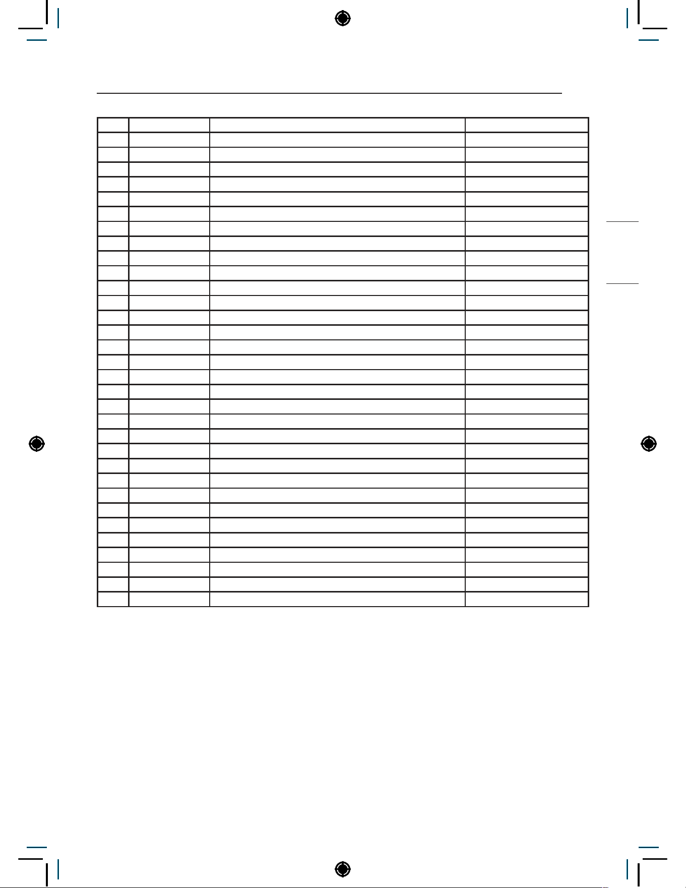
83
Programing Mode – Collect Mode
NON HEATER
18 ACr3 Accumulated Regular COS3 Cycle Count (0~65535)
19 ACr4 Accumulated Regular COS4 Cycle Count (0~65535)
20 ACr5 Accumulated Regular COS5 Cycle Count (for Heater) (0~65535)
21 ACr6 Accumulated Regular COS6 Cycle Count (for Heater) (0~65535)
22 SCPr ‘Add Super Wash’ Price
23 ItSC Interval ‘Add Super Wash’ Usage Count (0~65535)
24 ACSC Accumulated ‘Add Super Wash’ Usage Count (0~65535)
25 AUPr ‘Auto Dosing’ Price
26 ItAU Interval ‘Auto Dosing’ Usage Count (0~65535)
27 ACAU Accumulated ‘Auto Dosing’ Usage Count (0~65535)
28 ItSU Interval ‘Courtesy Cycle’ Usage Count (0~65535)
29 ACSU Accumulated ‘Courtesy Cycle’ Usage Count (0~65535)
30 ItFC Interval ‘Token’ Cycle Count (0~65535)
31 ACFC Accumulated ‘Token’ Cycle Count (0~65535)
32 ACrt Accumulated Run Time (minutes) (0~65535)
33 Itnr Interval No Runs (0~255)
34 Ittb Interval Trouble Cycle Count (0~255)
35 ItPd Interval Power Downs (0~255)
36 Itdd Interval Unauthorized Service Door Openings (0~255)
37 ItUC Interval Unauthorized Coin Vault Openings (0~255)
38 Ittl Interval Total Income (0~65535)
39 ACtl Accumulated Total Income (0~65535)
40 IttC Interval Total Cycle Count (0~65535)
41 ACtC Accumulated Total Cycle Count (0~65535)
42 Itd Interval Money (0~65535)
43 Acd Accumulated Money (0~65535)
44 ItSd Interval ‘Add Super Wash’ Money (0~65535)
45 ACSd Accumulated ‘Add Super Wash’ Money (0~65535)
46 ItA3 Interval ‘Auto Dosing’ Money (0~65535)
47 ACA3 Accumulated ‘Auto Dosing’ Money (0~65535)
48 ACdP Accumulated ‘WaveForce’ Operations (0~65535)
49 ACtL Accumulated ‘Tub Clean Course’ Cycle Count (0~65535)
50 ACPC Accumulated ‘Pre Clean’ Cycle Count (0~65535)
NOTE
• ‘Auto Dosing’ only counts paid Auto Dosing Cycles.
• Interval Cycles are reset to 0 after data is collected with Collect Card.
• Accumulated Cycles do not count Service or Trouble Cycles.
• Price settings vary by country.
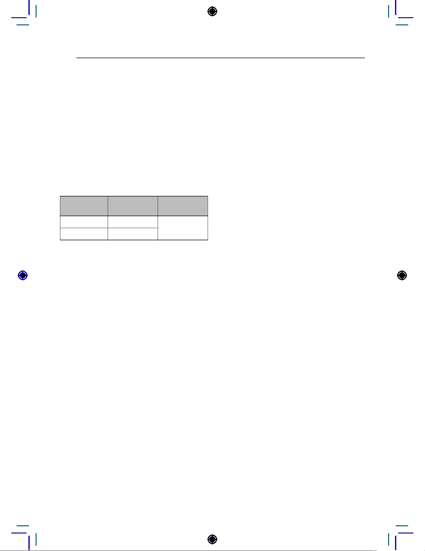
84
SMART FUNCTIONS
SMART FUNCTIONS
Open Source Software Notice Information
To obtain the source code under GPL, LGPL, MPL, and other open source licenses, that is contained in this
product, please visit http://opensource.lge.com. In addition to the source code, all referred license terms,
warranty disclaimers and copyright notices are available for download.
LG Electronics will also provide open source code to you on CD-ROM for a charge covering the cost of performing
such distribution (such as the cost of media, shipping, and handling) upon email request to [email protected].
This offer is valid for a period of three years after our last shipment of this product. This offer is valid to anyone in
receipt of this information.
Radio Equipment Specifications
Model
Name*1
Output
Power (Max.)
Frequency
Range
LCW-004 17.82 dBm
2412 MHz to
2472 MHz
LCW-007 17.59 dBm
*1 To identify RF module installed in the appliance, refer to the label attached to the appliance.
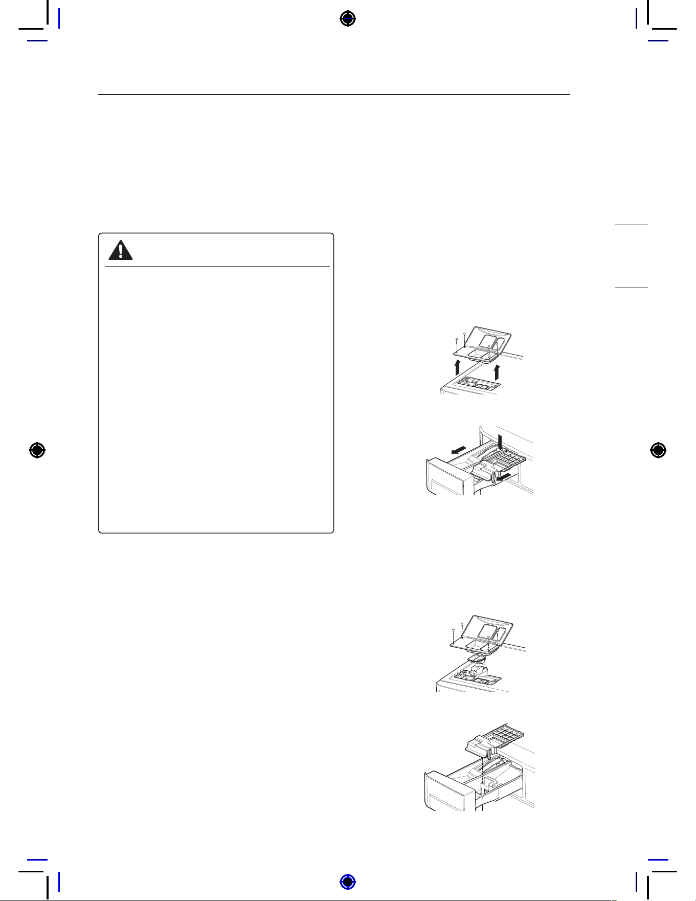
85
MAINTENANCE
NON HEATER
MAINTENANCE
Care after wash
After the cycle is finished, wipe the door and the
inside of the door seal to remove any moisture.
Leave the door open to dry the washer tub interior.
Wipe the body of the washing machine with a dry
cloth to remove any moisture
WARNING
• Unplug the washer before cleaning to
avoid the risk of electric shock. Failure to
follow this warning can cause serious injury,
fire, electrical shock, death.
• Never use harsh chemicals, abrasive
cleaners, or solvents to clean the
washer. They will damage the finish.
• Do not use volatile substances (benzene,
paint thinner, alcohol, acetone, etc.)
or detergents with strong chemical
components when cleaning the washing
machine. Doing so may cause discoloration
or damage to the machine, or it may cause
a fire.
• Certain internal parts are intentionally
not grounded and may present a risk of
electric shock only during servicing. Service
personnel - Do not contact the following
parts while the appliance is energized:
pump, valve, motor, control board.
Storing the Washer
If the washer will not be used for an extended
period of time and is in an area that could be
exposed to freezing temperatures:
1
Turn off water supply tap.
2
Disconnect hoses from water supply and drain
water from hoses.
3
Plug the power cord into a properly grounded
electrical outlet.
4
Add 1 gallon of nontoxic recreational vehicle
(RV) antifreeze to the empty wash drum. Close
door.
5
Unplug the power cord, dry the drum interior
with a soft cloth, and close the door.
6
Remove the inserts from the dispenser.
Drain any water in compartments and dry the
compartments.
7
Store the washer in an upright position.
8
To remove the antifreeze from the washer
after storage, run washer through a complete
cycle using detergent. Do not add laundry!
NOTE
• Not all of the RV antifreeze will be expelled.
• Weekly cleaning of the detergent dispenser will
ensure problem free operation.
Cleaning the Dispenser
1
The dispenser should be cleaned periodically
to remove buildup from detergent and other
laundry products.
- Single model -
- Stack model -
2
Remove the inserts from the drawer, and
clean them with warm water and a soft cloth
or brush to remove any residue or buildup.
Wipe out the inside of the drawer opening with
a damp cloth. Reassemble the drawer and
reinstall in the drawer opening.
- Single model -
- Stack model -
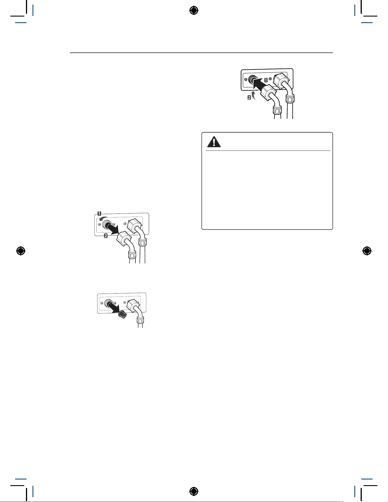
86
MAINTENANCE
NOTE
• Do not use anything other than water to clean
the drawer, inserts, and drawer opening.
Cleaning the Water Inlet Filters
Clean the water inlet filters periodically to prevent
clogging. Take extra care to clean the water inlet
filters for areas using hard water. Water may not
be supplied if there are foreign objects, such as
rust, sand, or stones in the water inlet filters.
1
Pull out the plug to turn off the washing
machine.
2
Turn off the faucets connected with the water
inlets.
3
Remove the water inlet hoses.
4
Pull out the water inlet filter.
Inlet Filter
5
Remove foreign objects from the water filter
inlet.
− Soak the water filter inlets in white vinegar
or a lime scale remover or use a toothbrush
to remove foreign objects and rinse
thoroughly.
6
Press the water filter inlets back into place.
7
Reattach the water lines to the washing
machine.
WARNING
• Unplug the power cord and turn off the
faucets before cleaning. Failure to do so
may cause electric shock.
• Do not use the washing machine without
the inlet filters. If you use the washing
machine without the inlet filters it will cause
leaks and malfunction.
• If you use the washing machine in an area
with hard water, the inlet filter may clog due
to lime buildup.
NOTE
• 1\E message will blink on the display when the
water pressure in the detergent drawer is weak
or an inlet filter is clogged with dirt. Clean the
inlet filter.
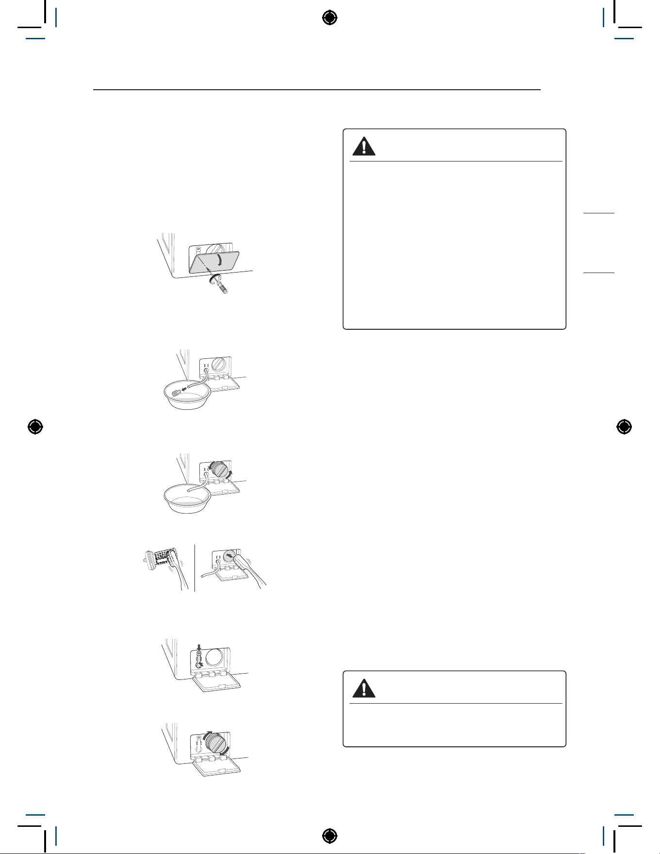
87
MAINTENANCE
NON HEATER
Cleaning the Drain Pump Filter
The washing machine fails to drain if the drain
pump filter is clogged. Periodically clean the drain
filter to prevent clogging with foreign objects.
1
Pull out the plug to turn off the washing
machine.
2
Open the drain pump filter cover.
3
Unclip the drain hose and remove the plug
from the drain hose to drain the remaining
water.
4
Twist the pump filter counterclockwise to
remove.
5
Clean the pump filter and opening.
6
Recap the plug onto the drain hose and
reattach the drain hose.
7
Insert the drain pump filter.
8
Close the drain pump filter cover.
WARNING
• Make sure to pull out the plug before
cleaning. Failure to do so may cause
electric shock.
• Opening the drain filter will result in water
overflowing if there is water in the washer
tub. Make sure to check if the water is
completely drained before opening the
drain filter.
• If you use the washing machine with the
drain filter reassembled incorrectly after
cleaning it, or if you use the machine without
the filter, it may cause leaks or malfunction
of the washing machine.
NOTE
• OE message will blink when the drain pump
filter is clogged with dirt. Clean the drain pump
filter.
Cleaning the Door Seal
Clean the door seal once a month to prevent build-
up of dirt in the door seal.
1
Wear rubber gloves and protective goggles.
2
Dilute 3/4 cup (177 ml) of liquid chlorine
bleach in 1 gallon (3.8 L) of water.
3
Soak a sponge or a soft cloth in this diluted
solution and wipe down all around the door
seal.
4
Wipe any moisture with a dry towel or cloth
after cleaning.
5
Leave the door open to allow the door seal to
dry completely.
CAUTION
• Cleaning the door seal with an undiluted
solution may cause malfunction of the door
seal and washing machine parts.

88
MAINTENANCE
Cleaning the Drum, Tub Clean
Using the washing machine in a humid space for a
long period of time may lead to a buildup of black
mold and germs in the air inside the washer tub
and affect your health. If you clean the washer tub
regularly on a monthly basis using TUB CLEAN it
will keep the washer tub clean for hygienic use.
1
Add tub cleaner or lime scale remover into the
detergent dispenser drawer.
− Do not exceed the maximum detergent limit
line when you add it. Detergent may remain
in the washer tub after cleaning.
− When you use liquid chlorine bleach, load it
into the liquid chlorine bleach compartment.
When you use a powdered cleaner, add it
into the main wash detergent compartment.
− When you use cleaning tablets, place them
directly into the washer tub. (Do not add
cleaning tablets to the drawer.)
2
Do operate tub clean.
NOTE
• Never load laundry while using TUB CLEAN.
The laundry may damage or become
contaminated. Make sure to clean the washer
tub when it is empty.
• Leave the door open after finishing the laundry
to keep the tub clean.
• TUB CLEAN should be repeated monthly.
• Safely and conveniently secure the door
slightly ajar with a magnetic door plunger. This
will promote air circulation and allow the interior
of the machine to dry.
NOTE
• Wave Force process during the Rinse step
helps in maintaining tub hygiene. The tub is
cleaned by rotating the water-filled tub at an
optimized RPM.
• Wave Force is intrinsic within the Rinse step.
No additional setting is required.
• Wave Force is NOT a substitute for the TUB
CLEAN cycle. TUB CLEAN should still be
repeated monthly to maintain hygienic use.
Removing Mineral Buildup
In areas with hard water, mineral scale can form
on internal components of the washer. Periodically
clean the mineral buildup on the internal
components to extend the lifespan of the washer.
Use of a water softener is recommended in areas
with hard water.
• Use a descaler, to remove visible mineral
buildup on the washer tub.
• After descaling, always run the Tub Clean cycle
before washing clothing
• Mineral scale and other spots may be removed
from the stainless steel tub using a soft cloth
soaked in stainless steel cleaner.
• Do not use steel wool or abrasive cleaners.
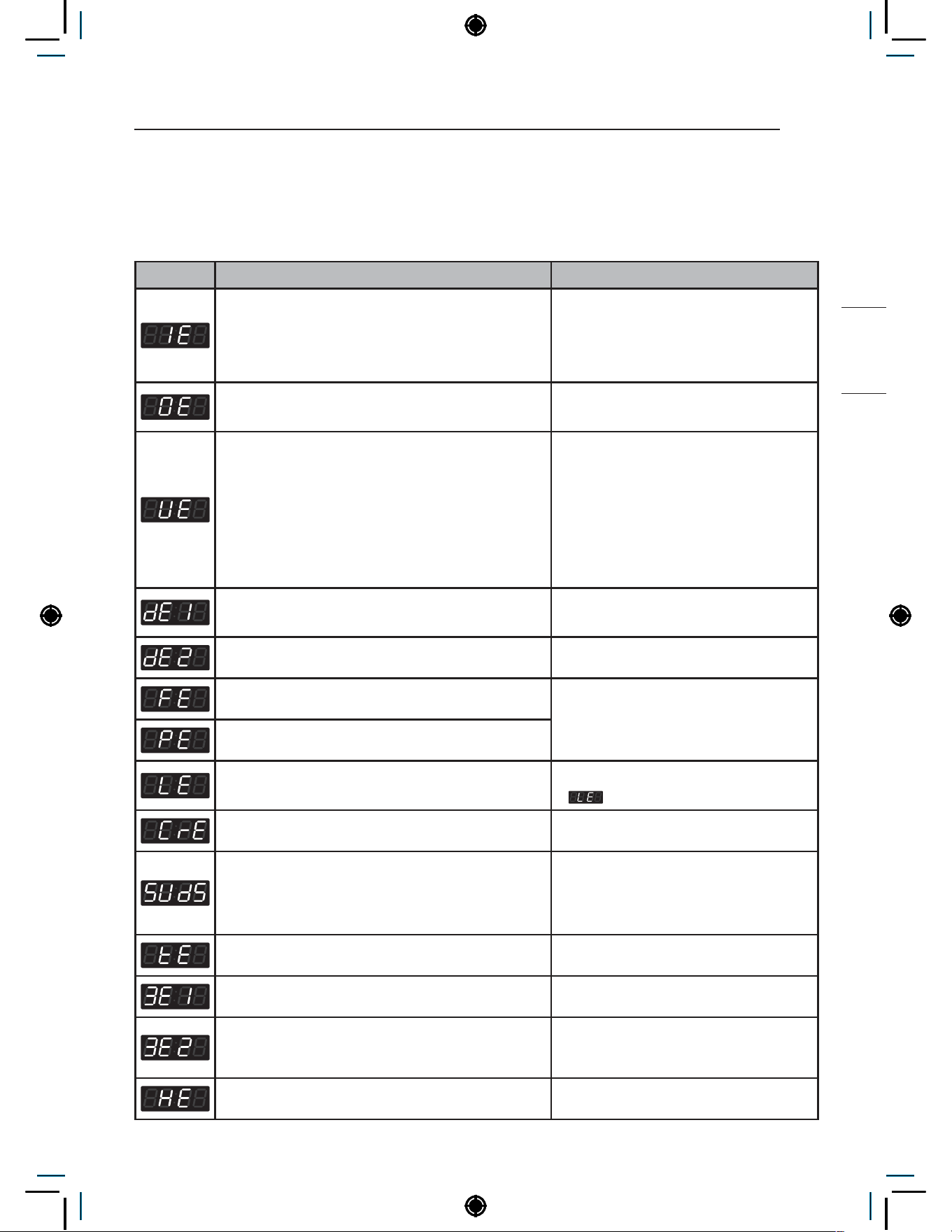
89
ERROR MODE
NON HEATER
ERROR MODE
Meaning of Error Codes that LED displays during occurrence of
problem.
Problem Possible Cause Solution
• Water supply is not adequate in area.
• Water supply taps are not completely open.
• Water inlet hose is bent.
• The filter of the inlet hose clogged.
Check another tap in the house.
Fully open tap.
Straighten hose.
Check the filter of the inlet hose.
• Drain hose is bent or clogged.
• The drain filter is clogged.
Clean and straighten the drain hose.
Clean the drain filter.
• Load is too small.
• Load is out of balance.
• The appliance has an imbalance detection and
correction system. If individual heavy articles
are loaded (bath mat, bath robe, etc.) and the
imbalance is too great, after several attempts to
restart the spin cycle the machine will stop and
the error code will be displayed.
Add 1~2 similar items to help balance
the load.
Rearrange the load in the tub to allow it
to balance properly.
• Is the door opened or not completely closed? Close the door completely.
* If it will not open, call for service.
• Door lock is broken. Check the door switch.
• The water overfills due to a faulty water valve. Close the water tap.
Unplug the power plug.
Call for service.
• The water level sensor malfunction.
• Overload in motor. Restart the cycle after 30 minutes.
If
is not released, call for service.
• Disconnection of card reader cable. Check the card reader wire.
• Too much detergent is used. This is not an error. It indicates a suds
removal routine.
It will clear and restart the cycle when
the suds are gone.
• Thermistor is opened or shorted. Thermistor should be replaced.
• Out of balance sensor is defective. Sensor should be replaced.
• Load is out of balance or the out of balance
sensor is defective.
Rearrange the load in the tub to allow it
to balance properly. If problem persists
replace the sensor.
• Malfunction in Heater system. Check the heater and wire.
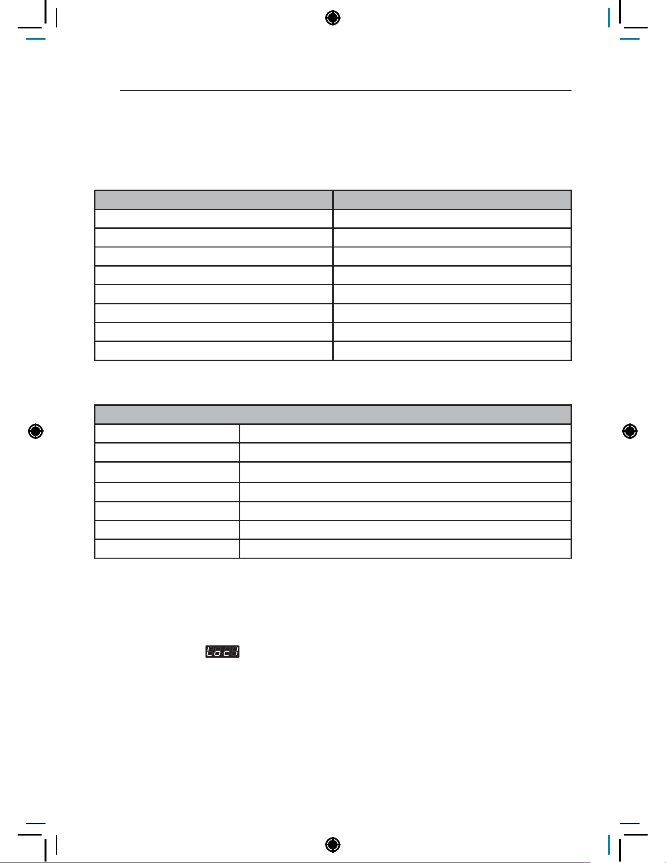
90
POWER FAIL RECOVERY
POWER FAIL RECOVERY
In case of power failure, the machine stops running but the time display remains on, showing the time just
before power failure.
DEFAULT WASHER SETTINGS
Default Settings Default
Wash Time 8 Minutes
Rinse Time 17 Minutes
Spin Time 11 Minutes
Rinsing times Twice
Coin #1 Value 0.1
Vend Price 2.00
Add super wash price 0.50
Top Spin speed 800 rpm
SPECIFICATIONS
Model
Power supply 220-240 V~ , 50 Hz , 3200-3800 W
Size 700 mm (W) X 770 mm (D) X 983 mm (H), 1396 mm (D with door open)
Weight 87 kg
Wash capacity 10.5 kg Max load(kg) based on IEC load
Sound pressure level Less than 70 dB
Spin speed 1200 rpm max.
Permissible water pressure 1.0-10.0 kgf/cm² (0.1-1.0 MPa)
NOTE
• Specifications subject to change by manufacturer.
• RPM depends on the selected cycle and load type.
• Price setting varies by country.
• Set your country from
• After EEPT, reset your country (Default country is EUK)
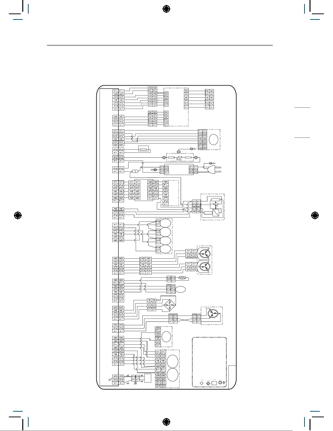
91
WIRING DIAGRAM
NON HEATER
WIRING DIAGRAM
Single type
SUB PCB
HOT
MOTOR
COIN DROP SIGNAL
OPTION2
COIN DROP VCC
<NOTE>
THERMISTOR
PRESSURE
SWITCH
DRAIN
PUMP
SOLE
NOID
INLET VALVE
NOISE
FILTER
POWER
CORD
CARD READER
OPTION1
EXTERNAL
FUSE
CIRCULATION
PUMP
AUTO DOSING
SYSTEM
DOOR LOCK SWITCH
VIBRATION
SENSOR
FUSE
FUSE
FUSE
WASHING
HEATER
DISPLAY PWB
CENTRAL
PAYMENT
CON1
Wi-Fi
BN
YL
RD
RD
RD
BK
BK
BK
BK
WH
SB
PK
GY
BK
BN
RD
OR
YL
BL
RD
BK
RD
PK
GY
SKY
WH
BK
BK
BN
OR
BN
YL
BL
RD
BK
BL
BK
BK
BK
BK
BK
YL YL
YL
YL
YL
YL
YL
BL
BL
BL
BK
BK
OR
BN
BK
BK
BK
OR OR
SKY
OR
BL BL
BL
WH WH
WH
SKY
SKY
SKY
SKY
RD
RD
RD
RD
RD
GY
SB
WH
WH GY GY
RD
MAIN PWB
RD BK YL RD WH BL WHYL
NA NA
VT
YL
YL
BL
BL
GY
WH
WH
WH WH
WH
BL WH
WH WH
NA
NA
RD
WH
BK
GN/YL
GN/
YL
GN
/
YL
WH
WH
U
V W
SLOT
SLOT
LOCK
SENSOR
BK
BL
BL
NA NA
RD BL BL
BN
NA
P
T
C
P
T
C
NA
NA
NA
#250 TERMINAL
#250 TERMINAL + HOUSING
PIN CONNECTOR
RING TERMINAL GROUND
Base/Line
n n
PWB
REACTOR
ATOMI
-ZING
MAIN BLEACH
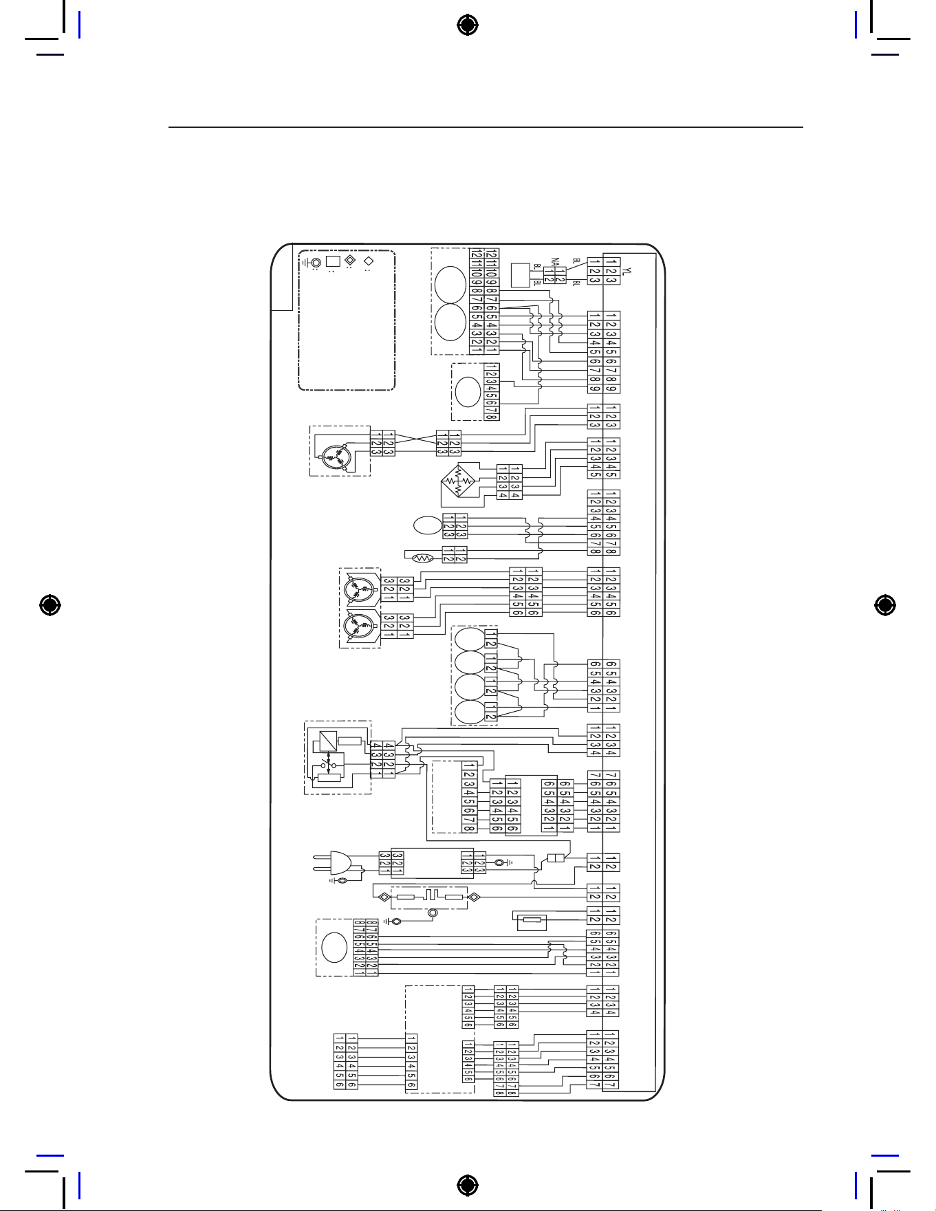
92
WIRING DIAGRAM
Stack type
�������
�������
�����
����������������
�������
�������������
������
����������
��������
������
�����
����
����
����
�����������
�����
������
�����
����
�����������
�������
��������
����
�����������
����
�����������
������
����������������
���������
������
����
����
����
�������
������
�����������
�������
�������
����
�����
��
��
��
��
��
��
��
��
��
��
��
��
��
��
��
��
��
��
��
��
��
��
��
��
���
��
��
��
��
��
��
��
��
��
��
��
��
��
��
��
��
����
��
��
��
��
��
��
��
��
��
��
��
��
��
��
��
����
���
��
����
��
����
��
���
���
���
���
��
��
��
��
��
��
��
��
������
��
��������
����������������
����
��
��
��
��
��
��
��
��
��
��
��
����
����
��
��
��
��
��
�����
���
��
��
�
��
��
��
�
��
����
����
����
������
��
��
��
����
����
��
��
��
�
�
�
�
�
�
��
��
��
�������������
�����������������������
�������������
��������������������
���������
��
���
REACTOR
����
������
�����
����
�����
����

Memo

Memo

Memo