IMPORTANT
READ THESE INSTRUCTIONS CAREFULLY BEFORE BEGINNING THE INSTALLATION. PROPER INSTALLATION
WILL PROVIDE SAFE AND EFFICIENT SERVICE, AND AVOID NEEDLESS EXPENSE NOT COVERED BY THE
WARRANTY. READ THE PRODUCT WARRANTY CONTAINED IN THIS MANUAL AND REMEMBER TO FILL
OUT AND RETURN TO THE MANUFACTURER ALL RELEVANT WARRANTY CARDS AND CERTIFICATES.
SHOULD YOU HAVE ANY QUESTIONS, PLEASE CONTACT YOUR LOCAL DEALER OR REFER TO THE
GETTING SERVICE FOR YOUR WATER HEATER SECTION OF THIS MANUAL.
SAVE THIS MANUAL FOR FUTURE REFERENCES.
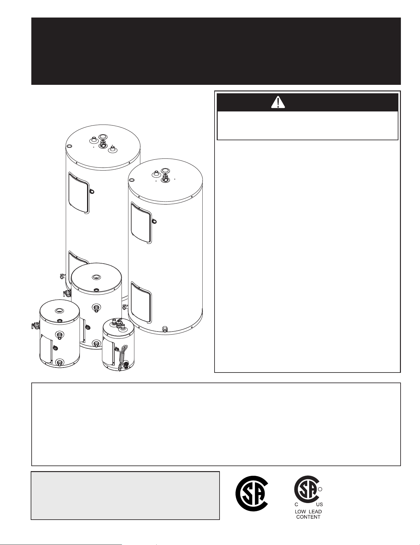
RESIDENTIAL ELECTRIC WATER HEATER
OWNER’S MANUAL
INSTALLATION AND OPERATING INSTRUCTIONS
If the information in these instructions is not
followed exactly, a fire or explosion may result causing
property damage, personal injury, or death.
•
DO NOT REMOVE the element and thermostat access
door before the power to the water heater is turned “
OFF
”.
•
DO NOT
ATTEMPT to repair or replace any of the
electrical components installed on the water heater before
the power to the water heater is
turned “
OFF
”
.
•
DO NO
T USE the water heater on a voltage other than
that specified on the water heater rating plate.
•
DO NOT
CONNECT the power supply wiring to
anywhere other than the main power connection on the
water heater.
•
DO NOT
TURN ON the power to the water heater unless
it is completely filled with water.
•
DO NOT
DRAIN the water heater unless the power
to the water heater has been turned
“
OFF
”
.
•
DO NOT
STORE or use gasoline or other flammable
vapours and liquids in the vicinity of this or any other
appliance.
WHAT TO DO IF YOU SMELL SMOKE
• Immediately turn “OFF” the power to the water heater.
• If after turning “OFF” the power the smoke
continues, call your local fire department.
• When the smoke has stopped, call a qualified service
technician to identify and repair the problem.
For your records, write the model and serial number here:
Model # ____________________________________
Serial # ____________________________________
GI-IM017En-0825
WARNING
AVERTISSEMENT
DANGER
C US
®
54000028
© 2025 A. O. Smith Enterprises Ltd. Printed in Canada
R
R
WARNING
AVERTISSEMENT
DANGER
WARNING
AVERTISSEMENT
DANGER
2
TABLE OF CONTENTS
Safety Information ................................ 2
Installation Instructions .......................... 3
Location ...................................... 3
Water Piping .................................. 3
Temperature & Pressure-Relief Valve ........... 3
Pressure Build-up in a Water System ............ 3
Filling the Water Heater ........................ 3
Electrical Connections .......................... 6
Insulation Blankets .............................. 6
Installation Checklist ........................... 8
Operating Instructions ........................... 8
Starting the Water Heater ...................... 8
Start-up Procedure .............................. 9
Safety Controls ................................. 9
Water Temperature Regulation ................. 9
General Maintenance ............................. 9
Condensation ................................. 9
Element or Thermostat Replacement ............. 9
Temperature and Pressure-Relief Valve ........ 10
Anode ....................................... 10
Draining the Water Heater .................... 11
Vacation ..................................... 11
Getting Service for your Water Heater .......... 11
Replacement Parts ............................... 12
Troubleshooting Guide .......................... 14
Warranty ........................................ 16
SAFETY INFORMATION
Your safety and the safety of others is extremely important during the installation, operation, and servicing of this water heater. Many
safety-related messages have been provided in this manual and on your water heater. Always read and obey all safety messages. These
messages will point out the potential hazard, tell you how to reduce the risk of injury, and tell you what will happen if the instructions are
not followed.
This is the safety alert symbol. This symbol alerts you to potential hazards that can kill or hurt you and others. All safety
messages will follow the safety alert symbol and either the word “DANGER” or “WARNING”.
Serious injury or death can occur if you do not
follow the instructions immediately.
Serious injury or death can occur if you do not
follow the instructions.
WARNING
AVERTISSEMENT
DANGER
DO NOT use this water heater if any part has been under water. Immediately call a qualified service
technician to inspect the water heater and to replace any part of the control system which has been
under water. Failure to follow this instruction can result in property damage, personal injury, or death.
Before proceeding with the installation instructions:
1) Inspect the water heater and its component parts for possible damage. DO NOT install or attempt to repair any damaged
component parts. If you detect any damage, contact the dealer where the water heater was purchased or the manufacturer
listed on the warranty card.
2) Verify that the voltage being supplied corresponds to that which is marked on the water heater rating plate.
IMPORTANT
These instructions have been written as a guide for the proper installation and operation of your water heater, and the
manufacturer of this water heater will not accept any liability where these instructions have not been followed. However, for
your safety and to avoid damage caused by improper installation, this water heater must be installed by a Certified Licensed
Professional, and meet all local codes or, in the absence of local codes, CSA C22.1 Canadian Electrical Code, in Canada,
and/or the National Electrical Code, ANSI/NFPA 70, in the United States.
INSTALLATION INSTRUCTIONS
TABLE OF CONTENTS
3
Location
This water heater should be located as close as possible to a power
supply and to the main use of hot water. This location must not
be subject to freezing temperatures. The water heater should be
positioned so that the element and thermostat access doors can be
removed for inspection, adjustment, and servicing of the elements
and thermostats. The drain valve must also be accessible. The water
heater must be located close to a suitable free-flowing floor drain.
Where a floor drain is not adjacent to the water heater, a suitable drain
pan must be installed under the water heater (see Figure 1A or 1B).
This drain pan should be at least two (2) inches (5.0 cm) larger than
the diameter of the water heater, and at least three (3) inches (7.5 cm)
deep providing access to the drain valve. This pan must be piped to
a suitable drain to prevent damage to property in the event of a water
leak from the piping, the relief valve, or the water heater.
Sooner or later, all water heaters leak. The manufacturer,
based on national building codes has given the necessary
advice to prevent damage to the building. Under no
circumstances is the manufacturer to be held liable for any
water damage in connection with this water heater.
Should this water heater be installed on carpeting, the carpeting must
be protected by a wood or metal panel beneath the water heater. This
panel must extend at least three (3) inches (7.6 cm) beyond the width
and depth of the water heater. Should the water heater be installed in
an alcove or closet, the entire floor area must be covered by the panel.
Water Piping
Refer to Figure 1A or 1B for a typical installation. Use of this layout
should provide a trouble-free installation for the life of the water heater.
Before making the plumbing connections, locate the COLD water inlet
and the HOT water outlet. These fittings are both 3/4” NPT male thread.
Female NPT fittings must be used during the installation. Make sure
that the dip-tube is installed in the cold water inlet (Top entry Models).
Install a shut-off valve close to the water heater in the cold water line. It is
recommended that unions be installed in the cold and hot water lines so
that the water heater can be easily disconnected, if servicing is required.
When assembling the hot and cold piping to the water heater,use Teflon™
tape and wrap it clockwise around all the threads or a good food grade of
pipe joint compound, and ensure all fittings are tight. It is imperative that
open flame is not applied to the inlet and outlet fittings, as heat will damage
or destroy the plastic lined fittings. This will result in premature failure of
the fittings, which is not covered by the warranty.
Temperature and Pressure-Relief Valve
DO NOT plug the temperature and pressure-relief valve or its
discharge line. DO NOT remove the relief valve. Make sure the
relief valve is properly sized for the water heater. If the relief
valve continuously discharges water, call a qualified service
technician to correct the problem. Failure to follow these instructions
can result in property damage, personal injury, or death.
To protect from excessive pressure and/or temperature, a temperature
and pressure-relief valve that meets the requirements of the Standard
for Relief Valves and Automatic Gas Shut-Off Devices for Hot Water
Supply Systems, CSA 4.4, in Canada, and ANSI Z21.22, in the United
States MUST BE installed by the installer when it has not been factory
installed. The relief valve should have a maximum set pressure that
does not exceed the hydrostatic working pressure of the water heater
(150 psi = 1,035 kPa) and a BTU/h rating equal to or greater than the
input rating, as shown on the water heater rating plate. It should never be
plugged or removed from the opening marked for it on the water heater.
If this relief valve should need to be replaced, use only a new tem-
perature and pressure-relief valve. Never install an old or existing relief
valve, as it may be damaged or inadequate for the working require-
ments of the new water heater. This new relief valve must meet all local
codes or, at a minimum, the requirements listed above. Never install
another type of valve between the relief valve and the water heater.
A discharge line must be installed into the relief valve. The discharge line:
• Must not be smaller than the outlet pipe size of the relief valve.
• Must not terminate less than six (6) inches (15.2 cm) and not more
than twelve (12) inches (30.5 cm) above a floor drain.
• Must not be restricted in any way. Do not thread, cap, or in any way
restrict the end of this outlet.
• Mustbeofamaterialcapableofwithstanding210˚F(99˚C)without
distortion.
• Must be installed to allow complete drainage of the relief valve and
discharge line.
• Must terminate over an adequate free-flowing drain.
Pressure Build-up in a Water System
When the water heater operates, the heated water expands creat-
ing a pressure build-up. This is a natural function and is one of the
reasons for installing a temperature and pressure-relief valve. If the
cold water supply line has a built-in water meter, check valve, or
pressure reducing valve, a suitable expansion tank must be installed
to prevent pressure build-up or water hammer effect, otherwise the
warranty is void (see Figure 1A or 1B). An indication of pressure
build-up is frequent discharges of water from the relief valve. If the
relief valve discharges water on a continuous basis, it may indicate a
malfunction of the relief valve, and a qualified service technician must
be called to have the system checked, and the problem corrected.
Filling the Water Heater
NEVER operate the water heater unless it is completely
filled with water. Failure to follow this instruction can result in
premature failure of the water heater and its component parts
that is not covered by the warranty.
Check that all of the water piping connections have been made. To
fill the water heater:
1) Make sure that the water heater drain valve is closed by inserting
a flat head screwdriver into the slot on the head of the drain valve
and turning the knob clockwise .
2) Open the cold water supply manual shut-off valve. This valve
must remain open, as long as the water heater is in use. NEVER
operate the water heater with the cold water supply manual
shut-off valve closed.
3) To make sure the water heater is completely filled with water, open
all of the hot water faucets in the house to let the air out of the
water heater and plumbing system. Leave the faucets open until a
constant flow of water is obtained.
4) Check all of the plumbing connections to make sure there are no
leaks.
INSTALLATION INSTRUCTIONS
WARNING
AVERTISSEMENT
DANGER
WARNING
AVERTISSEMENT
DANGER
4
INSTALLATION INSTRUCTIONS
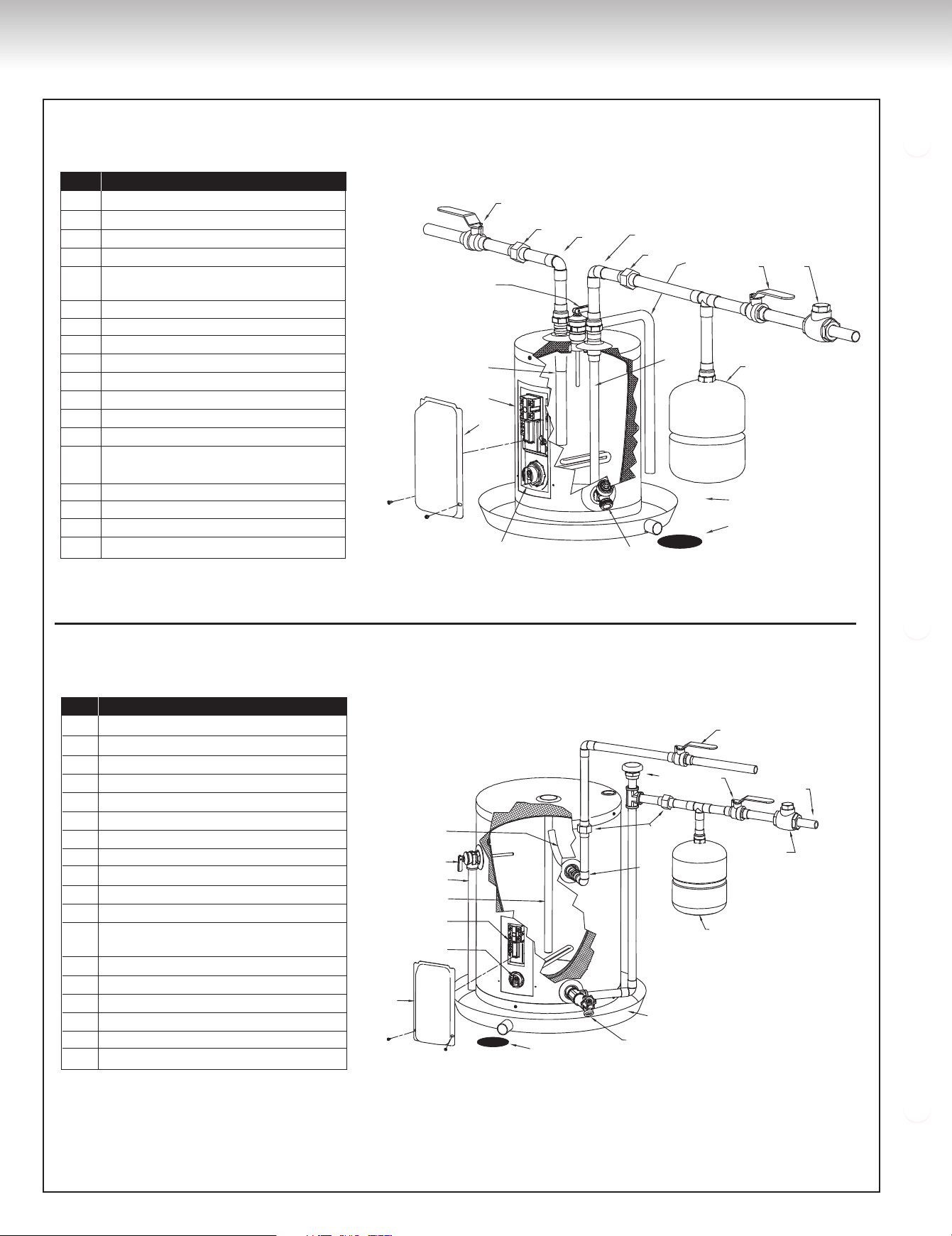
Figure 1A
Models with one (1) element, top entry
Models with one (1) element, side entry
INSTALLATION INSTRUCTIONS
3
2
1
16
15
14
13
11
10
8
7
6
9
4
5
12
17
18
ID No. Description
1 Hot water outlet
2 Union
3 Hot water manual shut-off valve
4 Temperature & pressure-relief valve
5 Combination outlet nipple /
magnesium anode
6 Thermostat / high limit assembly
7 Element and thermostat access door
8 Screw-in element
9 Drain valve
10 Free-flowing floor drain
11 Drain pan
12 Expansion tank
13 Dip-tube
14 Check valve, water meter or
pressure reducing valve
15 Cold water manual shut-off valve
16 Overflow tube
17 Union
18 Cold water intlet
16
15
14
13
11
12
1
2
4
5
6
3
7
17
18
9
10
8
ID No. Description
1 Outlet tube
2 Temperature & pressure-relief valve
3 Overflow tube
4 Magnesium anode
5 Thermostat / high limit assembly
6 Screw-in element
7 Element and thermostat access door
8 Free-flowing floor drain
9 Drain valve
10 Drain pan
11 Expansion tank
12 Check valve, water meter or
pressure reducing valve
13 Cold water inlet
14 Cold water manual shut-off valve
15 Unions
16 Hot water outlet
17 Vacuum breaker
18 Hot water manual shut-off valve
INSTALLATION INSTRUCTIONS
5
INSTALLATION INSTRUCTIONS
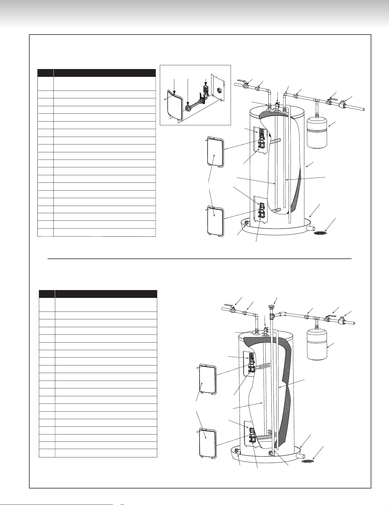
Figure 1B
Models with two (2) elements, top entry
Models with two (2) elements, bottom entry
ID No. Description
1 Check valve, water meter or
pressure reducing valve
2 Cold water manual shut-off valve
3 Union
4 Cold water intlet
5 Temperature & pressure-relief valve
6 Expansion tank
7 Overflow tube
8 Dip-tube
9 Drain pan
10 Free-flowing floor drain
11 Lower element
12 Drain valve
13 Element and thermostat access doors
14 Lower thermostat
15 Magnesium anode
16 Upper element
17 Thermostat / high limit assembly
18 Hot water outlet
19 Union
20 Hot water manual shut-off valve
1
2
3
4
5
19
20
6
7
9
10
11
12
13
14
17
18
15
16
8
13 16 17
Screw-in type element
ID No. Description
1 Check valve, water meter or
pressure reducing valve
2 Cold water manual shut-off valve
3 Union
4 Vacuum breaker
5 Temperature & pressure-relief valve
6 Expansion tank
7 Overflow tube
8 Drain pan
9 Free-flowing floor drain
10 Cold water intlet
11 Lower element
12 Drain valve
13 Element and thermostat access doors
14 Lower thermostat
15 Magnesium anode
16 Upper element
17 Thermostat / high limit assembly
18 Hot water outlet
19 Union
20 Hot water manual shut-off valve
1
6
7
8
9
10
11
12
2
3
4
5
19
20
13
14
15
16
17
18
6
INSTALLATION INSTRUCTIONS
Electrical Connections
This water heater uses an external electrical source for power.
It must be electrically grounded in accordance with all local
codes or, in the absence of local codes, CSA C22.1 Canadian
Electrical Code, in Canada, and/or the National Electrical Code,
ANSI/NFPA 70, in the United States. Failure to properly ground
this water heater can result in property damage, personal injury,
or death.
This water heater must be connected on a separate fuse branch
circuit. Check the water heater rating plate for the element wattage
and voltage and make sure that the power supply wiring and the
fusing or circuit breaker are the correct size for this water heater
(see Table 1). Verify that all of the wire connections on the element
and thermostat have been installed correctly, are secure, and that
none of the wires are grounded, have split, or are broken (see Figure
2A, 2B or 2C). If any of the original wiring needs replacing, use only
14AWG-type,orgreaterwirethatisapprovedfor221˚F(105˚C).
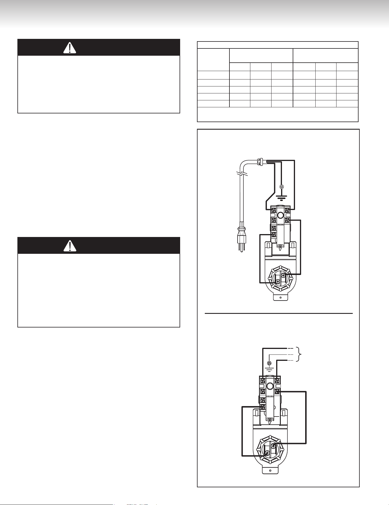
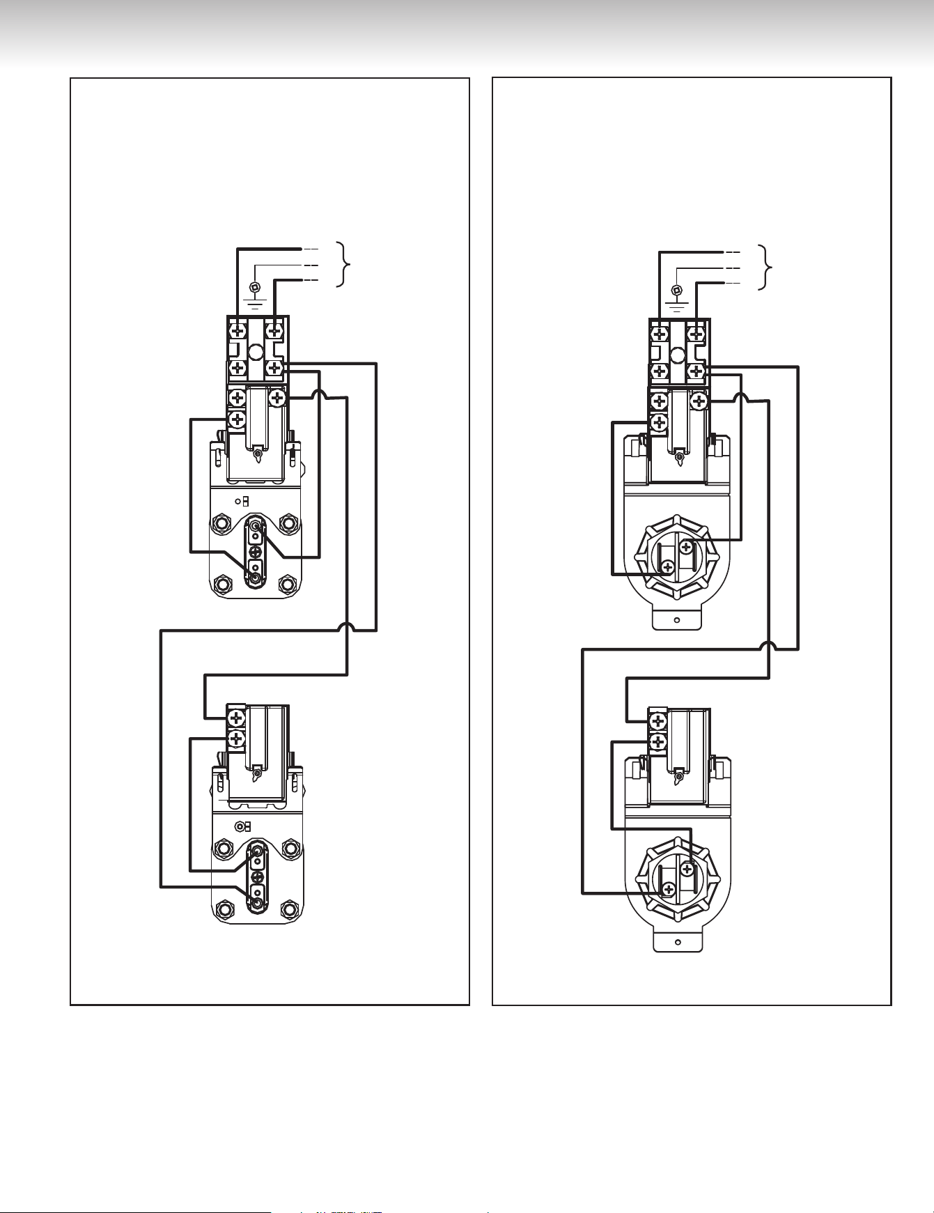
To hook-up the water heater to the power supply, connect the power
supply wiring to the red and black wires attached to the top
thermostat (see Figure 2A, 2B or 2C). NEVER CONNECT THE
POWER SUPPLY DIRECTLY ONTO THE THERMOSTAT.
Insulation Blankets
The manufacturer’s warranty does not cover any damage or
defect caused by installation, attachment, or use of any type of
energy saving or other unapproved devices (other than those
authorized by the manufacturer) into, onto or in conjunction with
the water heater. The manufacturer will not accept any liability
for loss or injury resulting from the use of such unauthorized
devices. The use of unauthorized energy saving devices may
shorten the life of the water heater and may result in property
damage, personal injury, or death.
Insulation blankets for external use on electric water heaters are
not necessary. The purpose of an insulation blanket is to reduce the
standby heat loss associated with the operation of storage tank water
heaters. This water heater meets or exceeds the NRCAN standards
with respect to insulation and standby loss requirements making an
insulation blanket unnecessary.
If local codes require the application of an external insulation blanket
to this water heater, pay careful attention to the following so as not to
restrict the proper function and operation of the water heater:
DO NOT cover the operating or warning labels attached to the water
heater or attempt to relocate them on the exterior of insulation blanket.
DO NOT cover the element and thermostat access door or tempera-
ture and pressure-relief valve.
Inspect the insulation blanket frequently.
WARNING
AVERTISSEMENT
DANGER
WARNING
AVERTISSEMENT
DANGER
BLUE
YELLOW
BLACK
WHITE
BLEU
JAUNE
NOIR
BLANC
BLUE
YELLOW
BLEU
JAUNE
VERT
GREEN
NOIR
ROUGE
Voltage
selon plaque
signalétique
Line voltage
according to
rating plate
BLACK
RED
BLUE
YELLOW
BLACK
WHITE
BLEU
JAUNE
NOIR
BLANC
BLUE
YELLOW
BLEU
JAUNE
VERT
GREEN
NOIR
ROUGE
Voltage
selon plaque
signalétique
Line voltage
according to
rating plate
BLACK
RED
Models with one (1) element, side entry
Figure 2A
Models with one (1) element, top entry
Recommended wire and breaker size
Element
Wattage
Recommended
Wire Size*
Recommended
Breaker Size
120V 208V 240V 120V 208V 240V
1,500 W #12 #14 #14 20A 15A 15A
3,000 W #10 #12 #12 30A 20A 20A
3,800 W --- #10 #12 --- 25A 20A
4,500 W --- #10 #10 --- 30A 25A
6,000 W --- --- #8 --- --- 40A
* Should conform to Local Codes.
The water heater must be grounded.
Table 1
INSTALLATION INSTRUCTIONS
INSTALLATION INSTRUCTIONS
7
INSTALLATION INSTRUCTIONS
Figure 2C
Models with two (2) elements - screw-in type
L1
G
L2
L1
G
L2
BLUE
BLUE
BLACK
BLACK
BLACK
BLACK
RED
RED
RED
YELLOW
YELLOW
BLEU
NOIR
NOIR
ROUGE
ROUGE
JAUNE
BLUE
BLACK
BLACK
BLACK
BLACK
RED
RED
YELLOW
BLEU
NOIR
NOIR NOIR
NOIR
ROUGE
ROUGE
JAUNE
BLEU
NOIR
NOIR
ROUGE
JAUNE
BLUE
BLUE
BLACK
BLACK
BLACK
BLACK
RED
RED
RED
YELLOW
YELLOW
BLEU
NOIR
NOIR
NOIR
ROUGE
ROUGE
ROUGE
JAUNE
BLEU
NOIR
NOIR
ROUGE
JAUNE
NOIR
ROUGE
Série 59T
Série AW
L1
G
L2
NOIR
ROUGE
L1
G
L2
BLACK
RED
L1
G
L2
BLACK
RED
L1
G
L2
NOIR
ROUGE
L1
G
L2
BLACK
RED
L1
G
L2
NOIR
ROUGE
L1
G
L2
BLACK
RED
L1
G
L2
BLACK
RED
BLACK
RED
NOIR
ROUGE
Voltage
selon plaque
signalétique
Line voltage
according to
rating plate
Voltage
selon plaque
signalétique
Line voltage
according to
rating plate
Voltage
selon plaque
signalétique
Line voltage
according to
rating plate
Voltage
selon plaque
signalétique
Line voltage
according to
rating plate
Voltage
selon plaque
signalétique
Line voltage
according to
rating plate
REVISE WITH LUC
Figure 2B
Models with two (2) elements - square flange and
TWIST-LOCK type
L1
G
L2
L1
G
L2
BLUE
BLUE
BLACK
BLACK
BLACK
BLACK
RED
RED
RED
YELLOW
YELLOW
BLEU
NOIR
NOIR
ROUGE
ROUGE
JAUNE
BLUE
BLACK
BLACK
BLACK
BLACK
RED
RED
YELLOW
BLEU
NOIR
NOIR NOIR
NOIR
ROUGE
ROUGE
JAUNE
BLEU
NOIR
NOIR
ROUGE
JAUNE
BLUE
BLUE
BLACK
BLACK
BLACK
BLACK
RED
RED
RED
YELLOW
YELLOW
BLEU
NOIR
NOIR
NOIR
ROUGE
ROUGE
ROUGE
JAUNE
BLEU
NOIR
NOIR
ROUGE
JAUNE
NOIR
ROUGE
Série 59T
Série AW
L1
G
L2
NOIR
ROUGE
L1
G
L2
BLACK
RED
L1
G
L2
BLACK
RED
L1
G
L2
NOIR
ROUGE
L1
G
L2
BLACK
RED
L1
G
L2
NOIR
ROUGE
L1
G
L2
BLACK
RED
L1
G
L2
BLACK
RED
BLACK
RED
NOIR
ROUGE
Voltage
selon plaque
signalétique
Line voltage
according to
rating plate
Voltage
selon plaque
signalétique
Line voltage
according to
rating plate
Voltage
selon plaque
signalétique
Line voltage
according to
rating plate
Voltage
selon plaque
signalétique
Line voltage
according to
rating plate
Voltage
selon plaque
signalétique
Line voltage
according to
rating plate
REVISE WITH LUC
8
OPERATING INSTRUCTIONS
Starting the Water Heater
Before turning on the power to your water
heater, make sure that you have read and
understood all of the instructions and warnings
in this manual and on your water heater. If you
have any questions about turning on your water
heater, immediately contact a qualified installer,
service agency, or the local electric utility.
DO NOT turn “ON” the power to this water heater if:
• It is not completely filled with water.
• The power supply voltage does not match the voltage listed
on the rating plate.
• Gasoline or other flammable vapours and liquids have been
stored in the vicinity of the water heater.
Failure to follow these instructions can result in property
damage, personal injury, or death.
WARNING
AVERTISSEMENT
DANGER
Installation Checklist
Location
• Is the water heater located close to a power supply and the main use of hot water? ....................................................................................
❒
• Is the water heater protected from freezing temperatures? ...........................................................................................................................
❒
• Has a drain pan been installed and piped to a free-flowing drain? ................................................................................................................
❒
• Can the element and thermostat access doors be removed for inspection, adjustment and servicing of the elements and thermostats? ......
❒
• Is the area where the water heater is located free of flammable vapours? ...................................................................................................
❒
Water Piping
• Is the dip-tube installed in the cold water inlet for models with top inlet connection? ...................................................................................
❒
• Has a temperature and pressure-relief valve been installed? ....................................................................................................................................
❒
• Does this valve have a discharge line installed, and is it piped to a free-flowing drain? ...............................................................................
❒
• Have all the plumbing connections been properly installed, and are they leak free? ....................................................................................
❒
• Is the water heater completely filled with water? ..........................................................................................................................................
❒
Wiring
• Does the power supply voltage match the voltage indicated on the water heater rating plate? ...................................................................
❒
• Has the correct size of wire and fusing or circuit breaker been used to supply the water heater with power? .............................................
❒
• Is the water heater electrically grounded? .....................................................................................................................................................
❒
• Have the electrical connections been checked, and are they secure? .........................................................................................................
❒
WARNING
AVERTISSEMENT
DANGER
If the information in these instructions is not
followed exactly, a fire or explosion may result causing
property damage, personal injury, or death.
•
DO NOT REMOVE the element and thermostat access
door before the power to the water heater is turned “OFF”.
•
DO NOT
ATTEMPT to repair or replace any of the
electrical components installed on the water heater before
the power to the water heater is
turned “OFF”
.
•
DO NO
T USE the water heater on a voltage other than
that specified on the water heater rating plate.
•
DO NOT
CONNECT the power supply wiring to
anywhere other than the main power connection on the
water heater.
•
DO NOT
TURN ON the power to the water heater unless
it is completely filled with water.
•
DO NOT
DRAIN the water heater unless the power
to the water heater has been turned
“
OFF
”
.
•
DO NOT
STORE or use gasoline or other flammable
vapours and liquids in the vicinity of this or any other
appliance.
WHAT TO DO IF YOU SMELL SMOKE
• Immediately turn “OFF” the power to the water heater.
• If after turning “OFF” the power the smoke
continues, call your local fire department.
• When the smoke has stopped, call a qualified service
technician to identify and repair the problem.
GENERAL MAINTENANCE
OPERATING INSTRUCTIONS
9
GENERAL MAINTENANCE
Start-up Procedure
1) Turn on the circuit breaker at the main service panel.
2) Make sure the fuse box or power switch (if one exists) next to the
water heater is pushed to “ON”.
3) If you smell smoke, refer to What to do if you smell smoke.
4) Wait one (1) hour. At this time, hot water should be available at the
faucet.
5) If after one (1) hour you do not have any hot water, check that the
fuse or circuit breaker is in working condition.
6) Wait another hour. If at this time you still do not have any hot
water, call a qualified service technician.
Note: If after one (1) hour you receive only a small amount of hot
water, check that the plumbing connections are not reversed.
Safety Controls
This water heater is equipped with a thermostat and high limit assembly
(ECO) that is located above the upper heating element. If for any reason
the temperature of the water becomes excessively high, the ECO will
break the power circuit to the heating element. Once the control opens,
it must be reset manually.
To reset the ECO:
1) Turn “OFF” the power to the water heater.
2) Remove the upper element and thermostat access door and the
insulation.
3) Press the red RESET button.
4) Replace the insulation and the element and thermostat access
door before turning “ON” the power to the water heater.
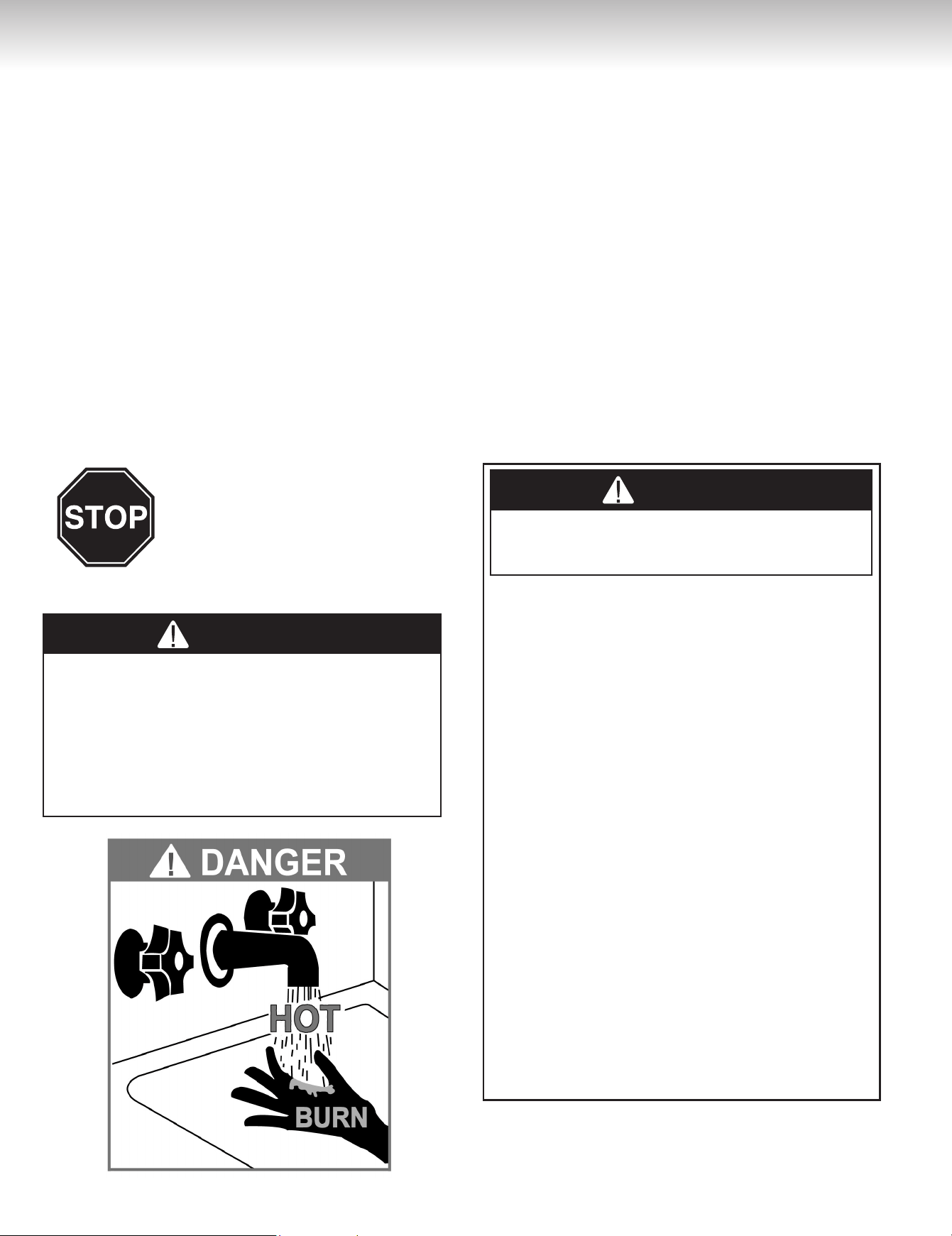
Water Temperature Regulation
The higher the setting, the greater the risk of scalding. Hot water
cancausethirddegreeburnsinunderone(1)secondat160˚F
(71˚C), in six (6) seconds at 140˚F (60˚C), and in thirty (30)
seconds at 130˚F (54˚C). In households where there are
children, physically challenged individuals, or elderly persons,
mixing valves for point of use are necessary as means of reducing
the scalding potential of hot water.
The thermostat is factory set at 140˚F (60˚C) for Canadian models
and125˚F(52˚C)forU.S.models.
To adjust the temperature on the thermostat:
1) Turn “OFF” the power to the water heater.
2) Remove the element and thermostat access door and the insulation.
On U.S. models DO NOT remove the thermostat protective cover.
3) Using a small flathead screwdriver, turn the thermostat dial to the
desired temperature.
4) Replace the insulation and the element and thermostat access
door before turning “ON” the power to the water heater.
Condensation
Condensation can form on the surface of the water heater:
1) When the water heater is filled with cold water for the first time.
2) If the water heater has been undersized.
3) When large amounts of hot water are drawn from the water heater
in a short period of time, and the refill water is very cold.
This condition is not uncommon and must never be misinterpreted
as a leaking tank. It will disappear once the water becomes heated.
Because the water can condense, it is very important that a drain
pan be installed under the water heater (refer to Figure 1A or
1B). Under no circumstances is the manufactu rer to be held
liable for any water damage, in connection with this water
heater. If the problem does not go away and water continues
to drip after the water heater has heated up, check all of the
plumbing connections to make sure they are not leaking.
Element or Thermostat Replacement
Before attempting to repair or replace any of the electrical
components on this water heater, turn “OFF” the power to the
water heater. Failure to do so could result in electrical shock and/
or property damage, personal injury, or death.
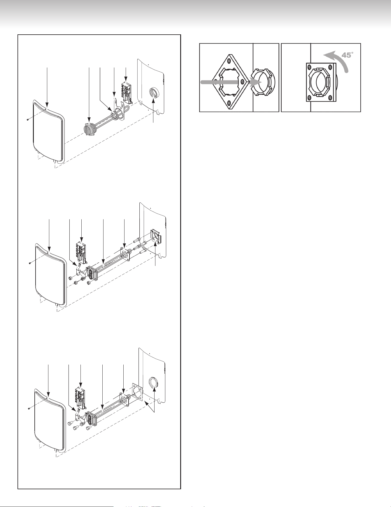
Replacing an Element (See Figure 3)
1) Turn “OFF” the power to the water heater and drain all of the water
from the water heater (see Draining the Water Heater, page 11).
2) Remove the element and thermostat access door and the insulation.
3) Disconnect the wires from the element terminals.
4) For a square flange element, undo the four (4) bolts securing the
element to the water heater.
For a screw-in element, with the help of a 1.5 inch socket wrench,
remove the element by unscrewing it from the water heater in a
counterclockwise motion.
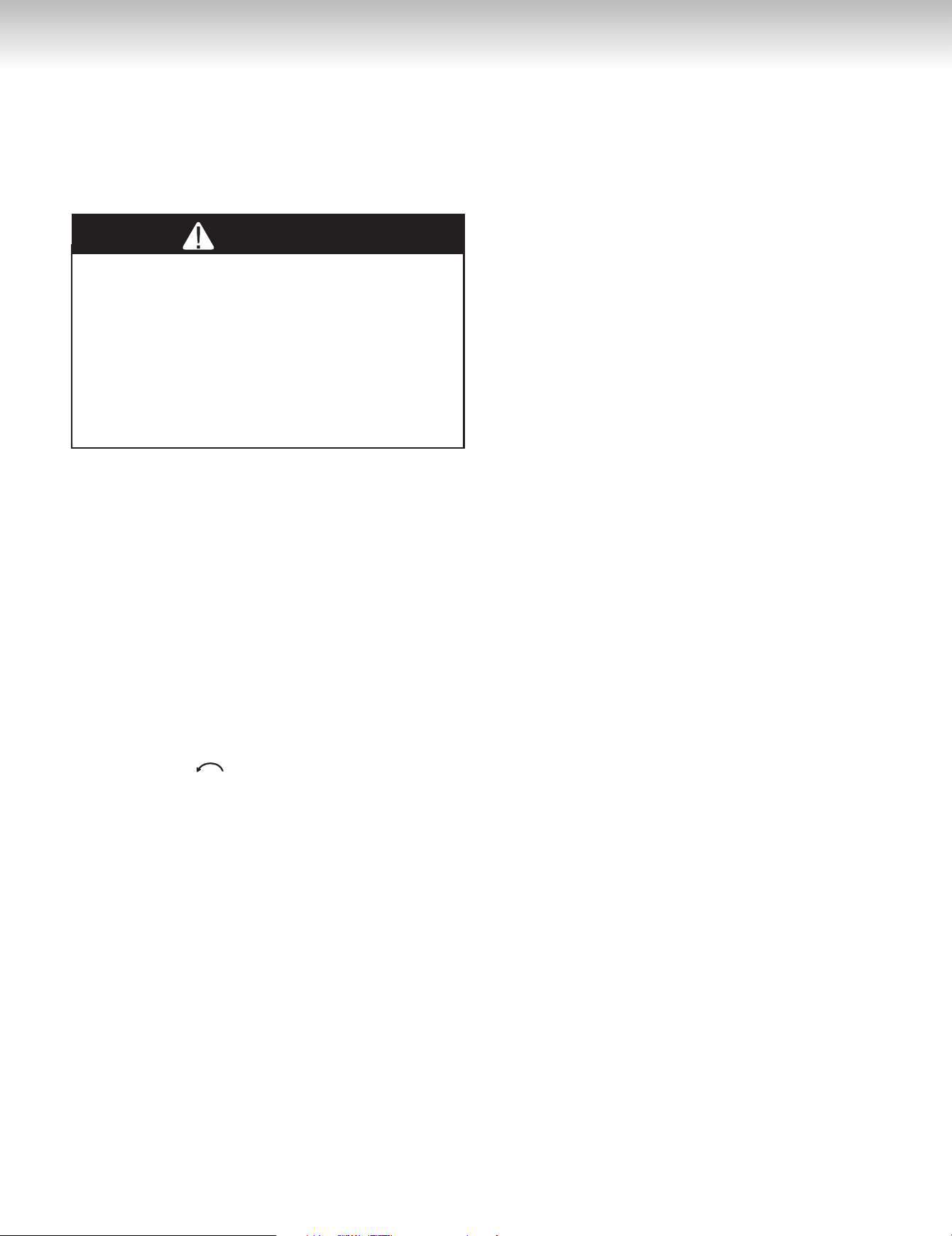
For TWIST-LOCK system, unscrew the four (4) bolts securing the
element to the water heater and pull element out of the tank. Make
sure the TWIST-LOCK flange is in the right position (
See Figure 4
).
5) Replace the element with a new element of the same wattage and
voltage. Make sure that the gasket surface is clean and that the
element has been re-installed water-tight with a new gasket.
6) Re-connect the wiring and tighten securely.
7) Re-fill the water heater (see Filing the Water Heater, page 3). DO
NOT TURN THE POWER ON TO THE WATER HEATER UNLESS
YOU ARE SURE IT IS COMPLETELY FILLED WITH WATER.
8) Inspect for any leaks and repair, if necessary
9) Replace the insulation and element and thermostat access door
before turning “ON” the power to the water heater.
WARNING
AVERTISSEMENT
DANGER
WARNING
AVERTISSEMENT
DANGER
10
GENERAL MAINTENANCE
Replacing a Thermostat (See Figure 3)
1) Turn “OFF” the power to the water heater.
2) Remove the element and thermostat access door and the
insulation.
3) Disconnect the wires from the thermostat terminals.
4) Lift the thermostat bracket arms and slide the thermostat up to
remove it.
5) Replace the thermostat with a new thermostat of the same manu-
facturer and type.
6) Reconnect the wires on the thermostat terminals referring to the
corresponding wiring diagram in Figure 2.
7) Set the thermostat to the desired temperature (see Water
Temperature Regulation, page 9).
8) Replace the insulation and element and the thermostat access
door before turning “ON” the power to the water heater.
Temperature and Pressure-Relief Valve
Manually operate the temperature and pressure-relief valve at least
once a year, standing clear of the outlet to avoid being burned. Lift
and release the operating lever on the valve to make it operate freely.
If, after manually operating the valve, it fails to completely reset itself
and continues to discharge water, replace it with a new one.
Anode
This water heater is equipped with an anode that is designed
to prolong the life of the glass-lined tank. The anode is slowly
consumed, protecting the glass-lined tank from corrosion. The anode
should be inspected every two (2) years. If more than half of the
anode has been consumed, it should be replaced. Instructions on
how to change the anode can be obtained from the manufacturer.
The life expectancy of the water heater is reduced where a water
softener is introduced to fight hard water. The sodium salts added
by a softener make the water extremely conductive, therefore,
the anode are consumed more rapidly. Under these conditions,
the magnesium anode must be replaced by an aluminum anode
approved by Giant, along with the addition of zinc pellets.
In certain water conditions, the anode will react with the water,
producing discoloured or smelly water. The most common complaint
is hot water that smells like rotten eggs. This phenomenon is the
result of the reaction between the magnesium of the anode and
hydrogen sulfide gas dissolved in the water, which occurs frequently
in well systems. This problem can usually be eliminated or reduced
Square flange element
09G, 9AG, 10G, 11G, 12G and 13G Models
(Until December 2012)
Type élément à bride carrée
Modèles 09G, 9AG, 10G, 11G, 12G et 13G
(jusqu’en décembre 2012)
Type élément à bride TWIST-LOCK
Modèles 09G, 9AG, 10G, 11G, 12G et 13G
TWIST-LOCK
flange element
09G, 9AG, 10G, 11G, 12G and 13G Models
1 2 3 4 5
6
1 - Access door
2 - Thermostat Bracket
3 - Thermostat
4 - Element
5 - Gasket
6 - Screw-in flange
Screw-in element
03G, 3AG and 04G Models
1 4 5 2 3
6
1 2 3 4 5
6
1 2 3 4 5
6
1 2 3 4 5
6
1 - Porte d'accès
2 - Support du thermostat
3 - Thermostat
4 - Élément
5 - Joint d'étanchéité
6 - Bride type vissé
1 - Access door
2 - Thermostat Bracket
3 - Thermostat
4 - Element
5 - Gasket
6 - Square flange
1 - Porte d'accès
2 - Support du thermostat
3 - Thermostat
4 - Élément
5 - Joint d'étanchéité
6 - Bride type carré
1 - Access door
2 - Thermostat Bracket
3 - Thermostat
4 - Element
5 - Gasket
6 - TWIST-LOCK
flange
1 - Porte d'accès
2 - Support du thermostat
3 - Thermostat
4 - Élément
5 - Joint d'étanchéité
6 - Bride type TWIST-LOCK
Type élément vissé
Modèles 03G, 3AG et 04G
1 4 5 2 3
6
Figure 3
Figure 4
GENERAL MAINTENANCE
GENERAL MAINTENANCE
by changing the magnesium anode to a type more suitable for these
conditions (aluminum anode) and by chlorinating the water heater
and plumbing system. If the problem persists, special filtration
equipment may be required. Under no circumstances is the anode to
be removed from the water heater on a permanent basis. Removal
of the anode will lead to premature failure of the water heater
and void the warranty.
Hydrogen gas can be produced in a hot water system that has
not been used for a long period of time (generally two [2] weeks
or more). HYDROGEN GAS IS EXTREMELY FLAMMABLE.
It is highly recommended to open the hot water faucet in
the kitchen for several minutes before you use any electrical
appliances connected to the hot water system, such as a
dishwasher or washing machine. If hydrogen gas is present,
there will be an unusual sound, such as air escaping through the
pipe, as the hot water faucet is opened. DO NOT smoke or intro-
duce an open flame near the faucet when it is opened.
Draining the Water Heater
Drain a pail of water through the drain valve at least once a year.
This will remove excess sediment from the bottom of the tank. This
sediment, if allowed to accumulate, will reduce the efficiency and the
life of the tank.
To completely drain the water heater:
1) Turn “OFF” the power to the water heater.
2) Close the cold water supply manual shut-off valve.
3) Connect one end of a garden hose to the water heater drain valve
and put the other end next to a free-flowing drain.
4) Open the drain valve by inserting a flat head screwdriver into
the slot on the head of the drain valve and turning the knob
counterclockwise .
5) Open a hot water faucet to allow air into the system.
Vacation
If you are planning a vacation or other prolonged absence, it is
essential to turn “OFF” the power to the water heater and the cold
water supply to the water heater. This preventive action will save
energy, protect against property damage in the event the water
heater leaks, and prevent the build-up of hydrogen gas. If the water
heater and piping are exposed to freezing temperatures, they should
both be drained. Remember to check the water heater thoroughly
after it has been shut off for an extended period of time before putting
it back in operation. Make sure that the water heater is completely
full of water, and that the cold water supply manual shut-off valve is
open, before turning “ON” the power to the water heater.
Getting Service for your Water Heater
If you are having problems with your water heater, follow these three
easy steps:
1) Read the Troubleshooting Guide contained in this manual
(see Page 14). It lists the most common problems experienced
with your electric water heater. The solutions you find listed may
provide a quick and simple solution to your problem and save you
time and money.
2) If the solution listed in the Troubleshooting Guide does not solve
the problem or if your particular problem is not listed in the guide,
contact the installer of the water heater, or the local electric utility.
3) If you still cannot solve the problem, contact the manufacturer’s
Customer Service Department by e-mail at service@giantinc.
com or by telephone at 1-800-363-9354, option 1. To help serve
you in a quick and efficient manner, always have the following
information ready:
a) Model number.
b) Serial number.
c) Date of installation.
d) Where the water heater was purchased.
e) Complete address where the water heater is installed.
f) A description of the problem.
11
GENERAL MAINTENANCE
WARNING
AVERTISSEMENT
DANGER
12
REPLACEMENT PARTS
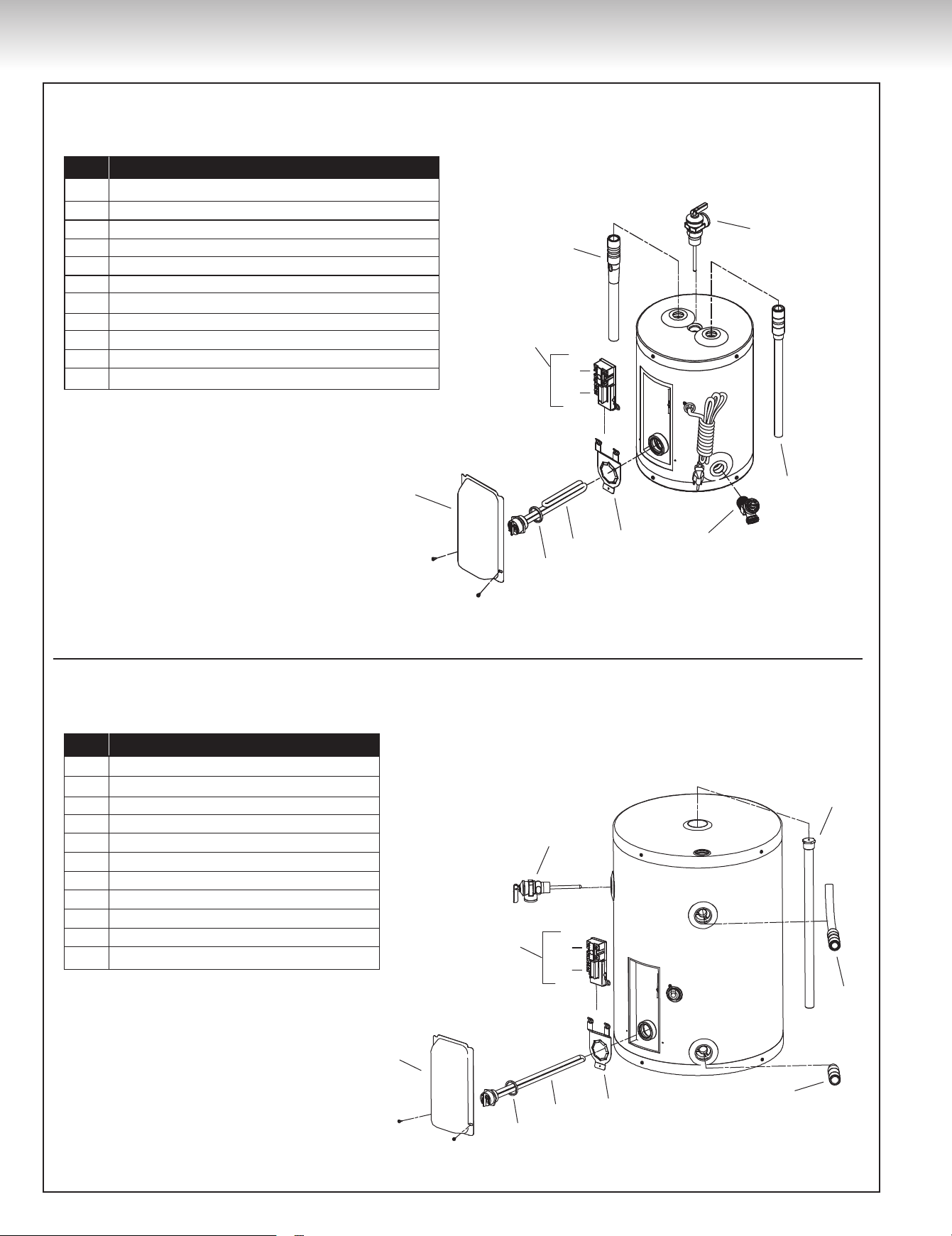
Figure 5A
Model with one (1) element, top entry
Models with one (1) element, side entry
REPLACEMENT PARTS
ID No. Description
1 Thermostat / high limit assembly
2 High limit with manual reset
3 Thermostat
4 Element and thermostat access door
5 Screw-in element gasket
6 Screw-in element
7 Thermostat bracket for screw-in element
8 Drain valve
9 Dip-tube
10 Temperature & pressure-relief valve
11 Combination outlet nipple/magnesium anode
1
2
3
4
5
6
7
8
9
10
11
ID No. Description
1 Thermostat / high limit assembly
2 High limit with manual reset
3 Thermostat
4 Element and thermostat access door
5 Screw-in element gasket
6 Screw-in element
7 Thermostat bracket for screw-in element
8 Inlet nipple
9 Outlet nipple with tube
10 Magnesium anode
11 Temperature & pressure-relief valve
1
2
3
4
5
6
7
8
9
10
11
REPLACEMENT PARTS
13
REPLACEMENT PARTS
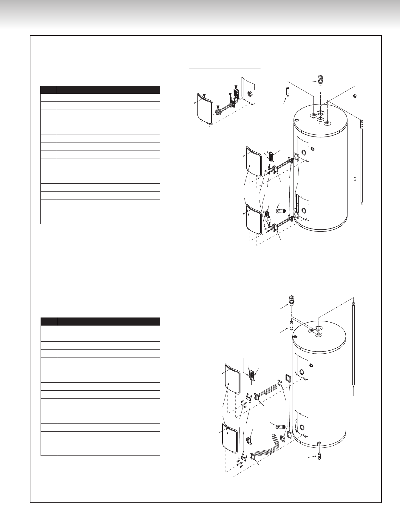
Figure 5B
Models with two (2) elements, top entry
Models with two (2) elements, bottom entry
ID No. Description
1 Thermostat / High limit assembly
2a High limit with manual reset
2b Thermostat
3 TWIST-LOCK Flanges
4 Element gaskets
5 Upper element
6 Drain valve
7 Lower Thermostat
8 Thermostat brackets
9 Machine bolts
10 Element and thermostat access doors
11 Lower element
12 Dip tube
13 Magnesium anode
15 Temperature & pressure-relief valve
16 Outlet nipple
Screw-in type element
1
14
15
4
3
2a
2b
5
6
10
7
12
13
8
9
11
10 5 8 1
ID No. Description
1 Thermostat / High limit assembly
2a High limit with manual reset
2b Thermostat
3 TWIST-LOCK Flanges
4 Element gaskets
5 Upper element
6 Drain valve
7 Lower Thermostat
8 Thermostat brackets
9 Machine bolts
10 Element and thermostat access doors
11 Lower element
12 Inlet nipple
13 Magnesium anode
14 Outlet nipple
15 Temperature & pressure-relief valve
14
1
2a
2b
4
3
5
6
7
8
9
10
11
12
13
15

14
TROUBLESHOOTING GUIDE
CONDITION CAUSE REMEDY
No hot water.
Dry-fired element. Replace with new element.
Main power supply is “OFF”. Turn “ON” main power supply.
Burnt fuse. Replace with new fuse.
Circuit breaker has tripped. Reset circuit breaker.
High limit with manual reset has tripped. Reset high limit control by pushing the red reset button.
Circuit breaker is defective. Replace with new circuit breaker.
Defective thermostat. Replace with new thermostat.
Defective element. Replace with new element.
Not enough hot water.
Water heater is undersized. Install size of water heater that meets demand.
High hot water demand. Increase the temperature of the thermostat.
Very cold water supply. Increase the temperature of the thermostat.
Wrong piping connections. Correct piping.
Sediment or lime accumulation at bottom
of water heater.
Drain water heater. Check to see if water treatment
is necessary.
Hot water plumbing system leaks. Check hot water plumbing system for leaks and repair.
Thermostat adjusted too low. Increase the temperature of the thermostat.
Defective thermostat. Replace with new thermostat.
Defective element. Replace with new element. In 90% of all cases it is
the bottom element.
Long runs or exposed piping. Insulate piping.
Hot water piping on outside wall. Insulate piping.
Defective dip-tube. Replace with new dip-tube.
Boiling hot water.
Thermostat temperature set too high. Lower the temperature on the thermostat.
Thermostat not in contact with water heater. Position properly. Be sure insulation is not interfering
with thermostat.
Element attacked by CO
2
. Replace with new element.
Defective thermostat. Replace with new thermostat.
Continuous operation.
Water heater is undersized. Install size of water heater that meets demand.
Element wattage too small. Replace with higher element wattage.
Thermostat not in contact with water heater. Position properly. Be sure insulation is not interfering
with thermostat.
Thermostat temperature set too low. Increase the temperature of the thermostat.
Defective thermostat. Replace with new thermostat.
Defective high limit with manual reset. Replace with new high limit with manual reset.
Element failure.
Wiring connections are wrong. See Figure 2 for correct wiring.
Wiring connections are loose. Locate, clean carefully, reconnect properly.
Lightning/Power surge. Inspect/replace fuse, element, and thermostat.
High voltage. Check with electrical utility and correct.
Short circuit. Locate short circuit and repair.
Thermostat failure.
No power. Inspect fuse/circuit breaker, replace/reset.
Loose wiring connection. Locate, clean carefully, reconnect properly.
Lightning/Power surge. Inspect/replace fuse, element, and thermostat.
Low/High voltage. Check with electrical utility and correct.
Short circuit. Locate short circuit and repair.
Blown fuse/circuit breaker.
Wiring connections are wrong. See Figure 2 for correct wiring.
Wiring connections are loose. Locate, clean carefully, reconnect properly.
Lightning/Power surge. Inspect/replace fuse, element, and thermostat.
High voltage. Check with electrical utility and correct.
Short circuit. Locate short circuit and repair.
Power supply wiring undersized. See Table 1 for correct wiring size.
Fuse burns instantly.
Short-circuit. Locate short circuit and repair.
TROUBLESHOOTING GUIDE

TROUBLESHOOTING GUIDE
15
TROUBLESHOOTING GUIDE
CONDITION CAUSE REMEDY
Fuse burns often.
Fuse contacts oxidized or fuse not
screwed in tight enough.
Clean contacts and tighten fuse.
Power supply wiring is undersized. See Table 1 for correct wiring size.
Smoking wiring.
Lightning/Power surge. Inspect/replace fuse, element, and thermostat.
Low/High voltage. Check with electrical utility and correct.
Power supply wiring undersized. See Table 1 for correct wiring size.
Service wires charred or hot.
Wiring connections are wrong. See Figure 2 for correct wiring.
Water heater not properly grounded. Properly ground the water heater.
Lightning/Power surge. Inspect/replace fuse, element, and thermostat.
High voltage. Check with electrical utility and correct.
Short circuit. Locate short circuit and repair.
Power supply wiring undersized. See Table 1 for correct wiring size.
Drain valve leaks.
Drain valve is open. Close the drain valve.
Defective drain valve. Replace with new drain valve.
Water drips from the
relief valve.
Excessive water pressure. Install a pressure reducing valve.
Thermal expansion in a closed water
system.
Install a suitable expansion tank on the cold water
supply line.
Improperly seated relief valve. Check relief valve works properly and replace, if necessary.
Defective thermostat. Replace with new thermostat.
Defective relief valve. Replace with new relief valve.
Water on the floor/drain pan.
Water discharge from the relief valve. See Pressure build-up in a water system (page 3).
Element leaks. Replace with new element.
Water heater leaks. Replace with new water heater
Condensation.
Water heater filled for the first time. Let water heater warm up. Problem should go away. If it
persists, check all plumbing connections for leaks.
Heavy draws of hot water with very cold
refill water.
Let water heater warm up. Problem should go away. If it
persists, check all plumbing connections for leaks.
Water heater is undersized. Install size of water heater that meets demand.
Wet insulation.
Leaking plumbing connections. Locate leak and repair.
Leaking around heating element. Tighten, clean, and smooth face of tank flange and
element gasket.
Water discharge from the relief valve. See Pressure build-up in a water system (page 3).
Singing element.
Build up of mineral deposits on element. Clean element, replace with new element if necessary.
Singing thermostat.
Thermostat not flush with tank. Install thermostat properly.
Wiring connections are loose. Locate, clean carefully, reconnect properly.
Traces of rust in
the hot water.
Anode has been eaten away. Replace new anode.
Rusty water.
Water corrosion. Replace with new water heater.
Rotten egg smell.
High sulfate or mineral content in water. Change magnesium anode to an aluminum anode and
bleach water heater.
Tank bulged.
No relief valve installed. Install proper relief valve.
Excessive water pressure. Install a pressure reducing valve.
Thermal expansion in a closed
water system.
Install a suitable expansion tank on the cold water
supply line.

STANDARD BASIC LIMITED WARRANTY
ON RESIDENTIAL ELECTRIC, GAS-FIRED WATER HEATERS AND STORAGE TANKS
(Hereunder referred to as “Unit” or “Equipment”)
GENERAL
The manufacturer warrants that, subject to verification of your warranty claim
within the warranty period described below, the necessary corrective actions
will be taken to either repair or replace the defective unit or component part
subject to the terms and conditions outlined in this document. Furthermore,
any replacement unit or component part supplied under warranty will carry
only the warranty remaining portion, based on the original unit installation
date. However, the warranty is limited to one (1) replacement unit. If due to
some unusual circumstance, a replacement unit or component part is found
to be defective by our inspection department, another unit or component part
will be provided in order to fulfill the obligation of the original warranty. This
warranty applies only to the original owner that purchased the unit, to the
unit original installation location, and it is not transferable. In order to benefit
from this warranty, the warranty reply card must be completed and sent back
to GIANT within forty-five (45) days of the unit purchase date, otherwise the
warranty will be as follows: SIX (6) years (for a residential water heater in
a family dwelling), FIVE (5) years (for a storage tank in a family dwelling)
and ONE (1) year (for any installation other than a family dwelling) from the
manufacturing date, without exception.
THE INNER TANK
If the warranty card is returned within the applicable time frame and the inner
tank leaks within the shorter of the two following periods: SIX (6)
1
years after
the original installation date or NINETY (90)
2
months after the manufacturing
date, whichever comes first, a replacement unit will be provided to the original
unit owner. Use of the equipment for purposes other than for a family dwelling
limits the warranty to ONE (1) year.
Exceptions:
1
: Or FIVE (5) years for storage tanks
2
: Or SEVENTY-EIGHT (78) months for storage tanks
COMPONENT PARTS
If any component part is found to be defective within ONE (1) year from the
original installation date, provided said defective part is an in-house factory
made piece or an original factory approved OEM piece, the manufacturer will
provide a replacement part after the receipt and testing of such part.
THIS WARRANTY DOES NOT APPLY IN THE FOLLOWING CASES:
1) To defects or malfunctions resulting from failure to properly install,
operate, or maintain the unit in accordance with the Owner’s Manual.
2) If the installation does not comply with CSA Standards, in particular, but
not limited to, the existing CSA-C652 Standard
(Installation of Electric
Storage Tank and Heat Pump Water Heaters for Residential Use)
,
CSA-B149.1
(Natural gas and propane installation code)
as well as any
other existing codes or standards, local regulations CSA-C22.1
(Canadian
Electrical Code)
, and good practices.
3) To any damage or failure caused by abuse, fire, floods, freezing, or other
acts of God.
4) To any damage or failure caused by operating the unit without an
approved temperature & pressure-relief valve having been installed.
5) To any damage or failure caused by powering any energy source while
the equipment is empty or partially empty or contains sediment build-up
resulting in dry firing of the heating elements.
6) To any damage or failure caused by connecting the unit to any other
source of energy not approved by GIANT or by operating the equipment
for other use than with potable water without any additives such as salt,
chlorine, or chemicals other than those added for the purpose of rendering
the water fit to drink.
7) To any damage or failure caused by the removal of the anode and/or by not
assuring that there is a working anode in the unit at all times. ‘‘All anodes
must be checked at least once every two (2) years & replaced,
if necessary’’. The installation of an anode that does not comply with
the requirements of the existing CSA-C309 Standard
(Performance
Requirements for Glass-Lined Storage Tanks for Household Hot Water
Service),
particularly in regards to the manufacturing, installation, and
composition of the replacement anode, will instantly void the warranty. The
same applies, but is not limited to, the non-compliance of the CSA-C191,
CSA-C22.2, and CSA-B149.1 Standards.
8) To any damage or failure caused by the use of the unit with a water
softener if the magnesium anode has not been replaced by an aluminum
anode approved by GIANT, as well as the addition of zinc pellets.
9) To any damage or failure caused by having affixed to the unit any non-
factory made or factory approved replacement part(s), such as elements,
controls, dip-tubes, anode, induced-current anode, relief valves, etc.
10) To any damage caused by not having the unit installed adjacent to a free-
flowing drain or in a pan or basin connected to such free-flowing drain.
11) For all equipment operated at water temperatures exceeding the
maximum operating setting of the thermostat and/or the high limit control,
at a pressure exceeding the one listed on the rating plate, for equipment
subject to a water-hammer effect that reverses the bottom of the tank,
units that are installed in a closed-looped system without any adequate
expansion tank
3
being installed as well as equipment installed in a system
equipped with a backflow preventer, a pressure-reducing valve, or any
other device, such as a check valve, without an adequate expansion tank
3
being installed.
3
: Or any other method accepted by the competent authority.
12) To any unit drained for wintering purposes.
13) To any performance issue caused by the poor selection of equipment,
power supply, wiring, or fuse / breaker.
14) To any unit from which the rating plate has been removed or altered.
15) To any break or damage caused by a water-hammer effect coming from,
but not limited to, a quick-closing valve, a solenoid valve, or any other
valves without an adequate pre-fabricated expansion tank being installed
in compliance with existing codes, standards, and good practices.
16) To any issue caused by the installation of water connections not
compatible with the equipment inlet and outlet ‘‘NPT’’ connections.
17) To any unit installed outside of Canada or the United States.
SERVICE LABOUR RESPONSIBILITY
This warranty does not cover any labour expense for diagnostic, service,
removal, or re-installation of a replacement unit. All such expenses are the
responsibility of the unit owner.
SHIPPING COSTS
If a unit or component part is deemed to be replaced, the manufacturer
will pay the transportation costs to ship said replacement unit or part to a
convenient authorized distributor or retailer of our choice. The unit owner
must pay for any local cartage including the cost of returning the replaced unit
or component part to the authorized distributor or retailer.
CLAIM PROCEDURE
Any claim covered by the warranty must be made to GIANT within a
maximum of thirty (30) days from the date the defect is first discovered.
Failure to provide a written notice for such defect to the manufacturer within
the allocated time frame will void the warranty. Any claim for warranty service
should be made with your contractor, wholesaler, or retailer from whom the
unit was purchased. In turn, said contractor, wholesaler, or retailer will contact
the manufacturer. If this procedure cannot be followed, please contact a local
contractor, wholesaler, or retailer distributing our products. For further warranty
information, please call our customer service department at (514) 645-8893 or
1-800-363-9354, option 1. In order to answer your call promptly, prior to
calling the factory, please make sure to have handy the unit model and serial
number that is found on the rating plate, on the side of the unit. Proof of
purchase showing the date and name of the business from whom the unit was
purchased is mandatory if the manufacturing date goes beyond the warranty
period offered by the manufacturer.
If an exact replacement unit is unavailable for whatever reason such as, but
not limited to, changes in government standards, the manufacturer agrees
to provide a unit or component part with comparable features. If government
regulations or industry standards require the replacement unit or component
part to have features not found on the defective unit or component part,
the unit owner will be charged the difference in price associated with these
required features. If such owner pays the difference in price for these required
features, they will benefit from a complete new Standard Basic Limited
Warranty for the replacement unit.
MISCELLANEOUS
No one is authorized to modify any conditions of this actual warranty.
The manufacturer will not honour any other warranty of any kind other
than what is offered. No claims for incidental or consequential damage
(including damage from leakage) will be accepted. If the warranty card is not
returned to us, a proof of purchase showing the name, date, and location
of the original point of purchase is mandatory to process any warranty
claim. Failure to provide such documentation will result in the lesser of
the warranty periods being offered, as stated in the ‘‘GENERAL’’ section.
In order to avoid any confusion and/or disputes, we suggest that the
warranty card be completed and returned to us no later than forty-
five (45) days after installation.
EXTENDED WARRANTY
For information concerning options for additional warranties on our residential
electric, gas-fired water heaters and storage tanks, contact your local
licensed plumber, an authorized retailer, or GIANT.
© 2024 A. O. Smith Enterprises Ltd. 11021, Notre-Dame E. Street, Montréal-East, Québec, Canada H1B 5H3 54000083 GI-PM019En-1124