
BULLETIN NO.
SERVICE PARTS LIST
54-26-2680
Jan. 2023
REVISED BULLETIN
DATE
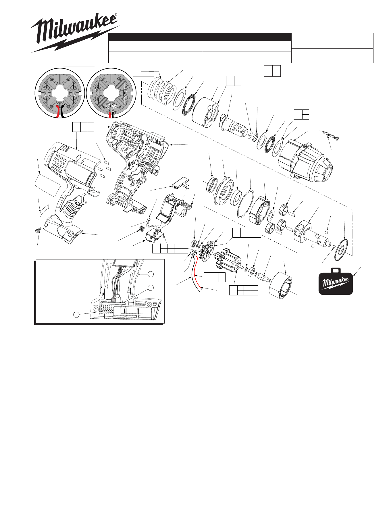
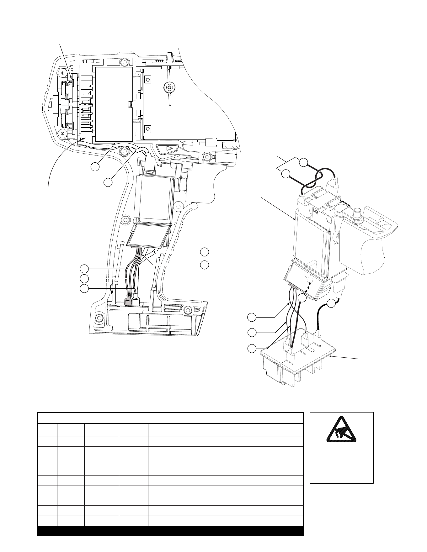
WIRING INSTRUCTION
FIG. PART NO. DESCRIPTION OF PART NO.REQ.
4 05-88-5988 M5 X 35mm Pan Hd. Slt. T-20 Screw (4)
5 14-30-0965
Front Housing Assy. w/ Bushing and O-Rings
(1)
6 --------------- Washer (2)
7 --------------- Thrust Bearing (1)
10 42-06-0690 3/4" Anvil (1)
12 --------------- Hammer (1)
13 02-80-0200 Thrust Bearing (1)
14 45-88-1006 Washer (1)
15 --------------- Compression Spring (1)
16 45-88-1650 Washer (1)
17 02-02-7010 7/32" Ball (1)
18 02-02-0250 1/4" Ball (2)
19 --------------- Camshaft (1)
20 32-65-0260 Ring Gear (1)
21 32-62-0500 Planet Gear (3)
22 44-60-1960 Pin (3)
23 45-88-1655 Washer (1)
24 02-04-0375 Ball Bearing (1)
25 34-40-0290 Seal Ring (1)
26 44-66-0895 Motor Mount Plate (1)
27 --------------- Ball Bearing - Front (1)
28 --------------- Pinion (1)
29 18-01-3025 Service Field Assembly (1)
31 --------------- Brush Card (1)
32 --------------- Washer (1)
33 --------------- Ball Bearing - Rear (1)
35 45-24-0570 Forward / Reverse Shuttle (1)
36 23-66-0427 Switch (1)
37 --------------- Connector Block (1)
38 40-50-1090 Compression Spring (1)
39 --------------- Handle - Left (1)
40 --------------- Handle - Right (1)
42 06-82-0995 M4 x 16mm Pan Hd. T-20 Screw (9)
See Page 3
B81A
STARTING
SERIAL NO.
2664-20
CATALOG NO.
M18™ 3/4" SQUARE IMPACT WRENCH
SPECIFY CATALOG NO. AND SERIAL NO. WHEN ORDERING PARTS
MILWAUKEE ELECTRIC TOOL CORPORATION
13135 W. LISBON RD., BROOKFIELD, WI 53005
Drwg. 9
FIG. PART NO. DESCRIPTION OF PART NO.REQ.
43 45-30-0255 Rubber Slug (4)
44 16-01-3030 Armature Assembly (1)
47 --------------- Retaining Ring (1)
48 31-44-0695 Handle Set (1)
49 45-22-0380 Rubber Cap (1)
50 22-56-1450 Switch/Connector Block Assembly (1)
56 34-40-1210 O-Ring (1)
58 44-90-4540 C-Ring (1)
61 --------------- Wire Harness (1)
62 12-20-2670 Service Nameplate Kit (1)
63 10-20-2998 Warning Label (1)
64 --------------- Washer (1)
65 42-55-2665 Carrying Case, Optional (1)
69 14-46-2070 Camshaft/Hammer Service Kit (1)
70 45-88-1877 Washer/Bearing Kit (1)
71 14-46-0755 Spring/Washer/Bearing Kit (1)
72 05-88-0928 M3 x 5mmPan Hd. T10 Screw (2)
73 45-88-1980 Spring Washer (2)
74 --------------- Leadwire Assembly - Red (1)
75 --------------- Leadwire Assembly - Black (1)
76 14-46-2395 Leadwire/Screw/Washer Kit (1)
77 14-46-2024 Brush Card Assembly (1)
0
EXAMPLE:
Component Parts (Small #) Are Included
When Ordering The Assembly (Large #).
00
Wire Harness
(61) plugs into
bottom of Switch (36).
NOTE:
Compression spring (38)
is positioned between the
bottom/back of the left
housing half (39) and the
back of the connector
block (37) as shown.
*
38
39
37
FIG. LUBRICATION
(Type 'Z' Grease, No. 49-08-7655):
20,21 Lightly coat the I.D. of the Ring Gear (20) and the center of
the three Planet Gears (21) with grease.
19 Place a dab of grease in ball grooves of the Cam Shaft (19).
10 Lightly coat the front washer surface of Anvil (10) with grease,
place a dab in the Ball hole on the backside of Anvil.
3 Coat outside grooves of Bushing (3) with grease.
12
15
14
13
56
58
6
7
6
5
4
16
49
26
24
25
20
23
21
22
19
18
17
61
35
39
38
37
40
43
62
63
42
48
39 40
43
36
65
10
12
19
69
6
7
70
71
13 14
15
L
Soldered Screwed
32
64
29
47
27
28
44
27 28 32
33 47 64
33
31
31 36 37 61
72 73 74 75
50
74
72(2x)
73(2x)
75
77
31 72 73
74 75
76
72 73
74 75
#77 Two styles of Brush Card
Assemblies See Page two
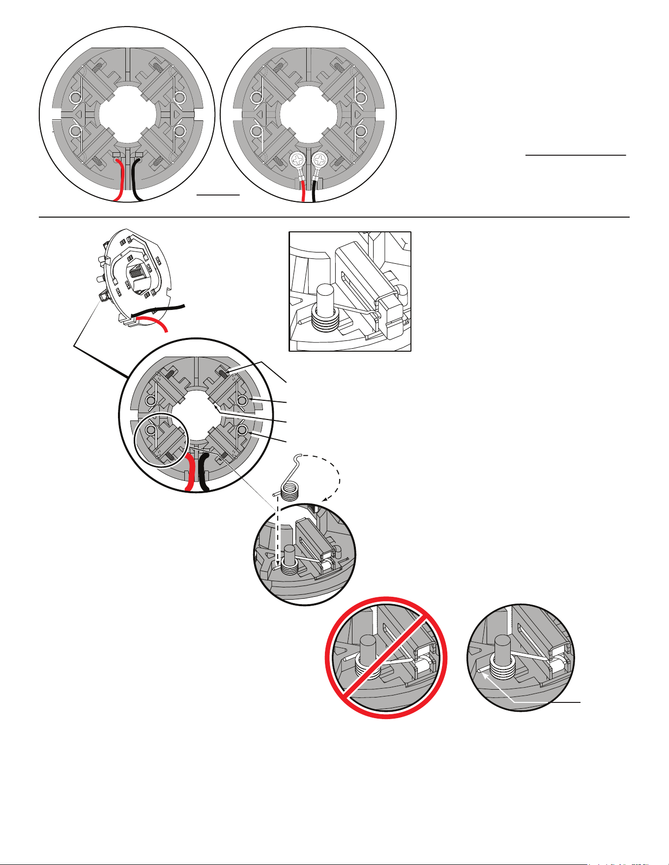
L
Soldered-
Original design
Screwed-
New design
Back View
Brush Card Assemblies
NOTE:
There are two Brush Card Assembly designs.
On the original brush card design the red and black wires
that go to the switch are soldered on the brush card.
On the new brush card design the red and black wires
that go to the switch are secured to the brush card with
spring washers and screws.
The new brush card design is directly interchangeable
in tools that have the old brush card design.
Be sure carbon
brush is in brush tube
with brush shunt moving
freely in side groove of tube.
Place brush spring over post with short leg
positioned downward as shown. Be sure spring
is completely down with short leg trapped against
'Y' shaped wall on brush card.
While holding spring in place, bring the long leg of
spring over the brush tube and through rear opening
of tube. Position rounded hook of spring in groove on
back of carbon brush. Be sure to check for free move-
ment between carbon brush, brush shunt and brush spring.
Brush Card Assy.
Brush Shunt (4 places)
Right Brush Spring (2x)
Carbon Brush (4x)
Left Brush Spring (2x)
Red
Black
CorrectWrong
Short leg of
spring to the
bottom
NOTE:
As an aid to prevent damage to the armature
commutator or the brushes when removing and
installing the armature assembly, it is recommended to
pull the carbon brushes partially back into the brush
tube. The carbon brushes will be held in place with the
brush spring moving from the rear of the brush to the
side of the brush.
In the unlikely event that the spring pops off follow the
instructions below.
2
1
7
5
6
9
8
Red
Black
Black
Red
White
Red
Black
BRUSH CARD
2
1
9
8
7
5
6
White
Red
Black
Black
Red
Black
Red
SWITCH
From Brush
Card
CONNECTOR
BLOCK
1 Black ----- ----- Component of the Switch/Connector Block Assembly.
2 Red ----- ----- Component of the Switch/Connector Block Assembly.
5 Red ----- ----- Component of the Switch/Connector Block Assembly.
6 Black ----- ----- Component of the Switch/Connector Block Assembly.
7 White ----- ----- Component of the Switch/Connector Block Assembly.
8 Black ----- ----- Component of the Switch/Connector Block Assembly.
9 Red ----- ----- Component of the Switch/Connector Block Assembly.
Terminals, Connectors and 1 or 2 End Wire Preparation
Wire
Color
Origin or
Gauge
Wire
No.
Length
WIRING SPECIFICATIONS
BULK LEAD WIRE - BULLETIN NO. 58-01-0003
Watch for pinched
wires in this area.
ATTENTION
OBSERVE PRECAUTIONS
FOR HANDLING
ELECTROSTATIC
SENSITIVE
DEVICES