
NOTE:
For the 2662-20 (serial break ‘D’):
Anvil (8) is being discontinued along with
corresponding Camshaft/Hammer Service Kit
(69). When inventories for the two parts are
depleted, the service replacement will be Cat.
No. 42-06-0061, Anvil/Camshaft Service Kit.
12
15
10
13
59
60
16
49
26
24
25
20
23
21
22
19
18
17
32
64
29
47
27
28
44
27 28 32
33 47 64
33
65
8
12
19
69
6
7
6
5
4
6
7
70
71
10 13
15
31
31 36 37 61
72 73 74 75
50
74
72(2x)
73(2x)
75
77
31 72 73
74 75
76
72 73
74 75
80
39
35
38
37
40
43
62
63
42
48
39 40
43
61
36
78
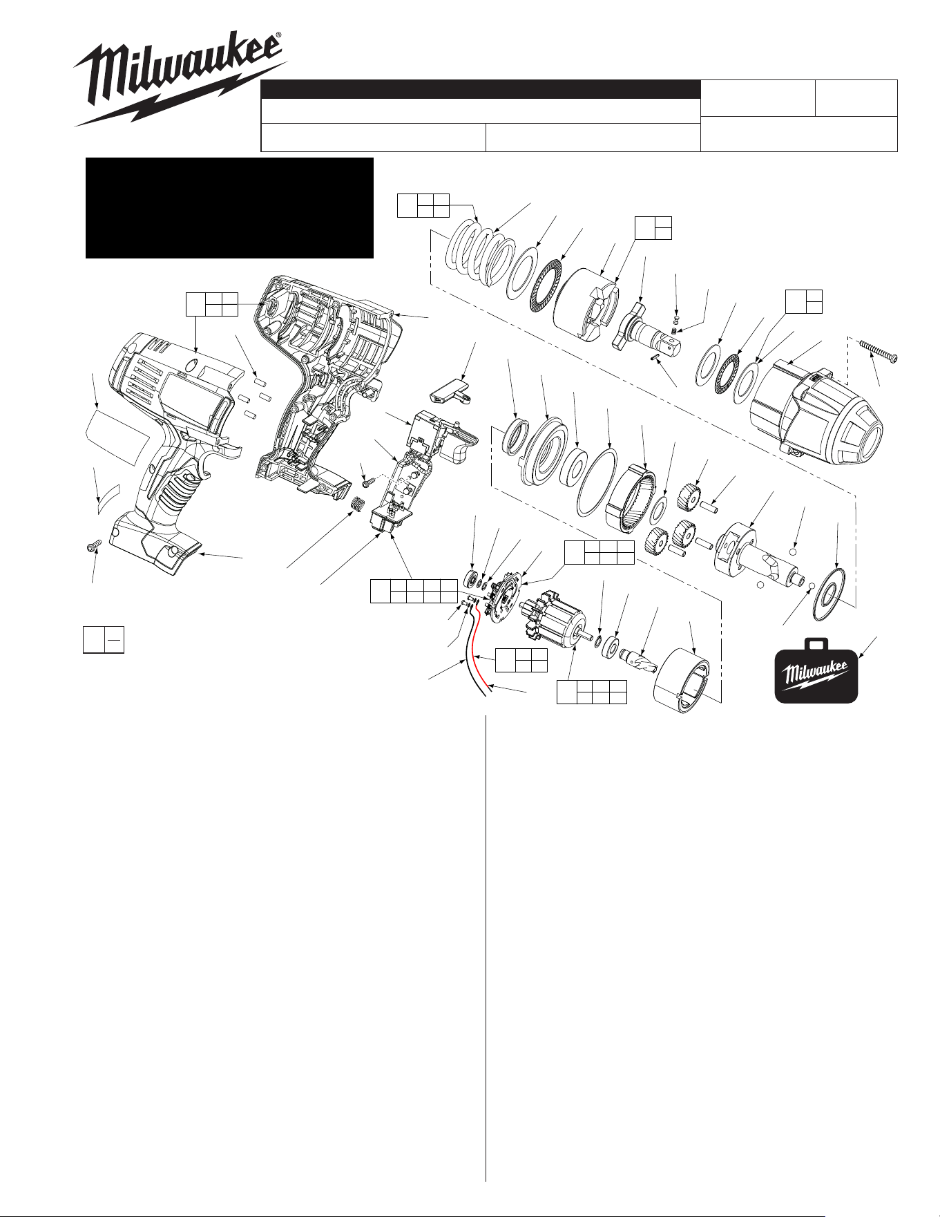
BULLETIN NO.
SERVICE PARTS LIST
54-26-2663
Jan. 2023
REVISED BULLETIN
54-26-2662
DATE
WIRING INSTRUCTION
FIG. PART NO. DESCRIPTION OF PART NO.REQ.
4 05-88-5988 M5 X 35mm Pan Hd. Slt. T-20 Screw (4)
5 14-30-0870
Front Housing Assy. w/ Bushing & O-Rings
(1)
6 --------------- Washer (2)
7 --------------- Thrust Bearing (1)
8 42-06-0057 1/2" Anvil (1)
10 45-88-1006 Washer (1)
12 --------------- Hammer (1)
13 02-80-0200 Thrust Bearing (1)
15 --------------- Compression Spring (1)
16 45-88-1650 Washer (1)
17 02-02-7010 7/32" Ball (1)
18 02-02-0250 1/4" Ball (2)
19 --------------- Camshaft (1)
20 32-65-0260 Ring Gear (1)
21 32-62-0500 Planet Gear (3)
22 44-60-1960 Pin (3)
23 45-88-1655 Washer (1)
24 02-04-0375 Ball Bearing (1)
25 34-40-0290 Seal Ring (1)
26 44-66-0895 Motor Mount Plate (1)
27 --------------- Ball Bearing - Front (1)
28 --------------- Pinion (1)
29 18-01-3025 Service Field Assembly (1)
31 --------------- Brush Card (1)
32 --------------- Washer (1)
33 --------------- Ball Bearing - Rear (1)
35 45-24-0570 Forward / Reverse Shuttle (1)
36 --------------- Switch (1)
37 --------------- Connector Block (1)
38 40-50-1090 Compression Spring (1)
39 --------------- Handle - Left (1)
40 --------------- Handle - Right (1)
42 06-82-0995 M4 x 16mm Pan Hd. T-20 Screw (9)
43 45-30-0255 Rubber Slug (4)
44 16-01-3030 Armature Assembly (1)
47 --------------- Retaining Ring (1)
48 31-44-0696 Handle Set (1)
See Page 3
B79D
STARTING
SERIAL NO.
2662-20
CATALOG NO.
M18™ 1/2" SQUARE IMPACT WRENCH
SPECIFY CATALOG NO. AND SERIAL NO. WHEN ORDERING PARTS
MILWAUKEE ELECTRIC TOOL CORPORATION
13135 W. LISBON RD., BROOKFIELD, WI 53005
Drwg. 3
FIG. PART NO. DESCRIPTION OF PART NO.REQ.
49 45-22-0380 Rubber Cap (1)
50 22-56-1451 Switch/Connector Block Assembly (1)
59 44-60-0597 Detent Pin (1)
60 40-50-0925 Detent Spring (1)
61 --------------- PCBA (1)
62 12-20-2670 Service Nameplate Kit (1)
63 10-20-2695 Warning Label (1)
64 --------------- Washer (1)
65 42-55-2665 Carrying Case, Optional (1)
69 14-46-2070 Camshaft/Hammer Service Kit (1)
70 45-88-1877 Washer/Bearing Kit (1)
71 14-46-0755 Spring/Washer/Bearing Kit (1)
72 05-88-0928 M3 x 5mmPan Hd. T10 Screw (2)
73 45-88-1980 Spring Washer (2)
74 --------------- Leadwire Assembly - Red (1)
75 --------------- Leadwire Assembly - Black (1)
76 14-46-2395 Leadwire/Screw/Washer Kit (1)
77 14-46-2024 Brush Card Assembly (1)
78 06-82-2395 M2.6 x 10 Pan Hd. T-8 Screw (1)
80 44-60-0465 Roller Pin (1)
FIG. LUBRICATION
(Type 'Z' Grease, No. 49-08-7655):
20,21 Lightly coat the I.D. of the Ring Gear (20) and the center of
the three Planet Gears (21) with grease.
19 Place a dab of grease in ball grooves of the Cam Shaft (19).
8 Lightly coat the front washer surface of Anvil (8) with grease,
place a dab in the Ball hole on the backside of Anvil.
2 Coat outside grooves of Bushing (2) with grease.
0
EXAMPLE:
Component Parts (Small #)
Are Included When Ordering
The Assembly (Large #).
00
= Part number change from
previous service parts list.
«
«
«
«
«
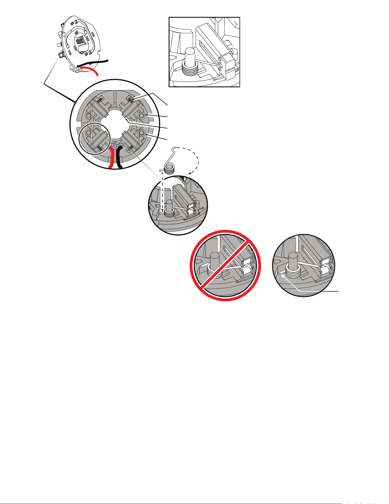
Be sure carbon
brush is in brush tube
with brush shunt moving
freely in side groove of tube.
Place brush spring over post with short leg
positioned downward as shown. Be sure spring
is completely down with short leg trapped against
'Y' shaped wall on brush card.
While holding spring in place, bring the long leg of
spring over the brush tube and through rear opening
of tube. Position rounded hook of spring in groove on
back of carbon brush. Be sure to check for free move-
ment between carbon brush, brush shunt and brush spring.
Brush Card Assy.
Brush Shunt (4 places)
Right Brush Spring (2x)
Carbon Brush (4x)
Left Brush Spring (2x)
Red
Black
CorrectWrong
Short leg of
spring to the
bottom
NOTE:
As an aid to prevent damage to the armature
commutator or the brushes when removing and
installing the armature assembly, it is recommended to
pull the carbon brushes partially back into the brush
tube. The carbon brushes will be held in place with the
brush spring moving from the rear of the brush to the
side of the brush.
In the unlikely event that the spring pops off follow the
instructions below.
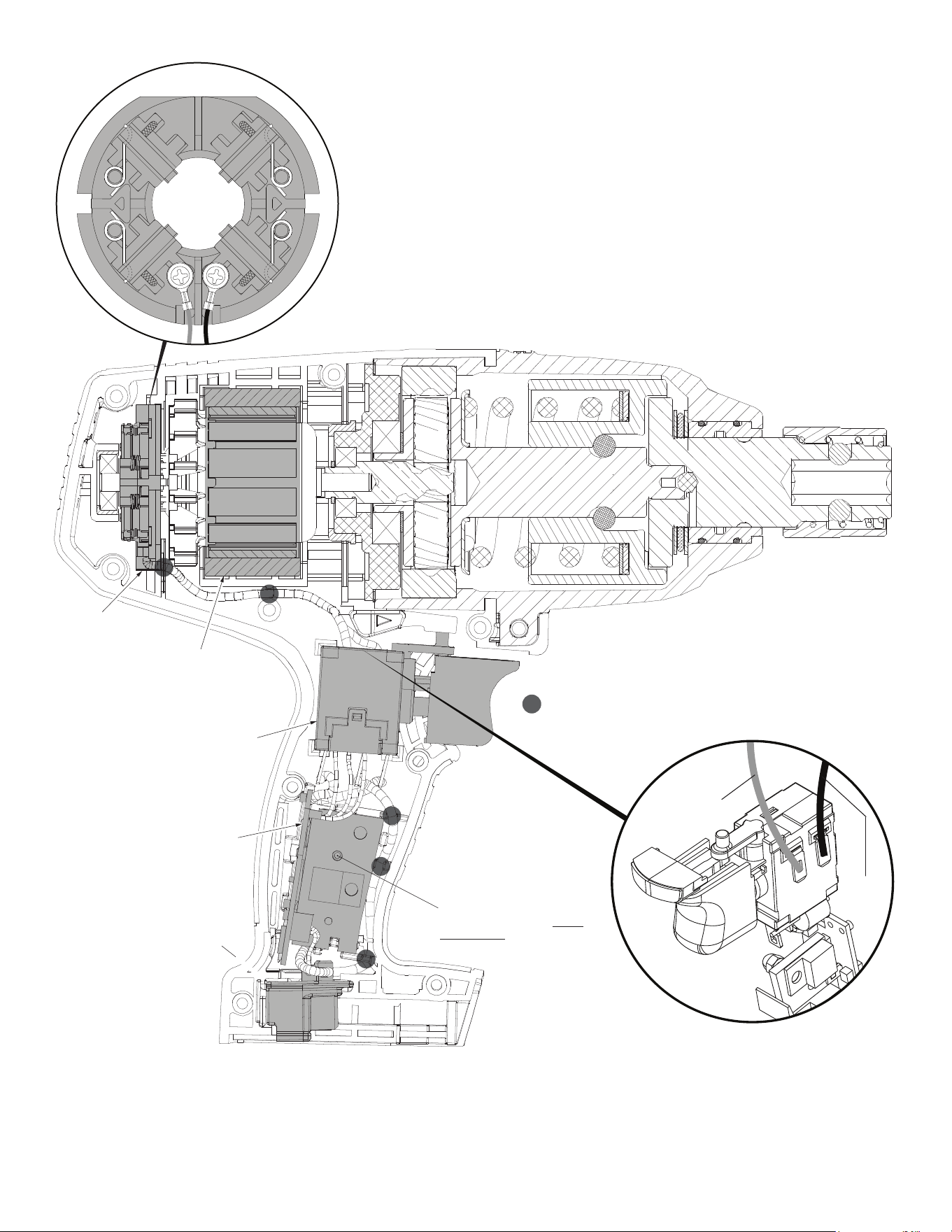
AS AN AID TO REASSEMBLY, TAKE NOTICE OF WIRE ROUTING AND
POSITION IN WIRE GUIDES AND TRAPS WHILE DISMANTLING TOOL.
BE SURE THAT ALL COMPONENTS OF THE ELECTRONICS KIT
ARE SEATED FIRMLY AND SQUARELY IN THE HANDLE RECESSES.
AVOID PINCHED WIRES, BE SURE THAT ALL WIRES AND SLEEVES
ARE PRESSED COMPLETELY DOWN IN WIRE GUIDES AND TRAPS.
PRIOR TO INSTALLING THE HANDLE COVER ONTO THE HANDLE
SUPPORT, BE SURE THAT THERE ARE NO INTERFERENCES.
Red Wire
Red wire
from top front
position on switch to left brush card position
(marked with an ‘L’).
Black wire from top rear position on switch to
right brush card position (marked with an ‘R’).
Black
Wire
= WIRE TRAPS
or GUIDES
Brush Card
Assembly
Field
On-Off
Switch
PCBA
Battery Terminal
Connector Block
Model 2665-20
Shown
L R
Rear View
Brush Card Assembly
NOTE:
Care must be taken not to
over tighten this screw!
Secure by hand only.