
BULLETIN NO.
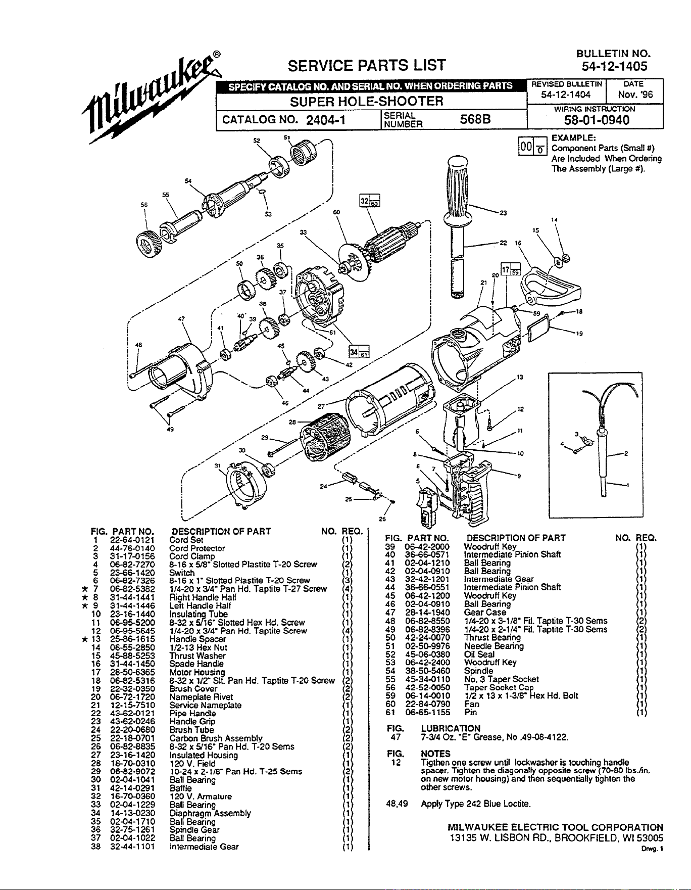
54-12-1405 SERVICE PARTS LIST
m
EXAMPLE:
00 B Component Parts (Small #)
P
Are Included When Ordering
The Assembly (large t).
FIG. PART NO.
1 22-64-0121
2 44-76-0140
3 31-17-0156
4 06-82-7270
5 23-66-1420
6 06-82-7326
* 7 06-82-5382
* 8 31-44-1441
R 9 31-44-1446
10 23-16-1440
11 06-95-5200
12 06-95-5645
* 13 25-86-1615
14 06-55-2850
15 45-88-5253
16 31-44-1450
17 28-50-6365
18 06-82-5316
19 22-32-0350
20 06-72-l 720
21 12-15-7510
22 43-62-0121
23 43-62-0246
24 22-20-0680
25 22-18-0701
26 06-82-8835
27 23-16-1420
28 18-70-0310
29 06-82-9072
30 02-04-1041
31 42-14-0291
32 16-70-0360
33 02-04-1229
34 14-13-0230
35 02-04-1710
36 32-75-1261
37 02-04-1022
38 32-44-l 101
DESCRIPTION OF PART NO. RED
Cord Set
Cord Protector
Cord Clamp
8-16 x 5%’ Slotted Plastite T-20 Screw
Switch
8-16 x 1’ Slotted Plastite T-20 Screw
l/4-20 x 3l4’ Pan Hd. Tapti te T-27 Screw
Riaht Handle Half
Lelt Handle Hali
lnsulati Tube
8-32 x
zg
16’ Slotted Hex Hd. Screw
l/4-20 x 3/4’ Pan Hd. Taptite Screw
Handle Spacer
l/2-13 Hex Nut
Thrust Washer
Soade Handle
lu(otorHousing
8-32 x lfr Sit Pan Hd. Taptite T-20 Screw
Brush Cover
Nameplate Rivet
Service Nameplate
Pioe Handle
Handle Grip
Brush Tube
Carbon Brush Assembly
8-32 x 916 Pan Hd. T-20 Sems
Insulated Housing
120 V. Field
10-24 x 2-l/8’ Pan Hd. T-25 Sems
$j$,pkn9
120 V. Armature
Ball Bearing
D&$zihmz&Assembly
Soindle Gear
Ball Bearina
Inlermedia~ Gear
it)
FIG. PART NO.
39 06-42-2000
40 36-66-0571
41 02-04-1210
42 02-04-0910
43 32-42-1201
44 36-66-0551
45 06-42-1200
46 02-04-0910
47 28-14-1940
48 06-82-8550
49 06-82-8396
50 42-24-0070
51 02-50-9976
52 45-06-0380
53 06-42-2400
54 38-50-5460
55 45-34-0110
56 42-52-0050
59 06-14-0010
60 22-84-0790
61 06-65-l 155
DESCRIPTION OF PART
Woodruff Key
Intermediate Pinion Shaft
Ball Bearing
Ball Bearing
Intermediate Gear
Intermediate Pinion Shaft
Woodruff Key
Ball Bearing
Gear Case
114-20 x 3-l/8’ Fil. Taptite T-30 Sems
l/4-20 x 2-114’ Fit. Taptite T-30 Sems
Thrust Bearing
Needle Bearing
Oil Seal
$-?$[r/ Key
No. 3 Taper Socket
Taper Socket Ca
l/2 x 13 x l-3/8’ R ex Hd. Bolt
&
FIG.
LUBRlCATlON
47 7-3/4 Oz. ‘E’ Grease, No .49-08-4122.
NOTES
Tigthen one screw until lockwasher is touching handle
spacer. Tighten the diagonally opposite screw (70-80 Ibs./in.
on new motor housing) and then sequentiilly tighten the
other screws.
48.49 Apply Type 242 Blue Loctite.
MILWAUKEE ELECTRIC TOOL CORPORATION
13135 W. LISBON RD.. BROOKFIELD, WI 53005
Dnvg. ’