OPERATING AND MAINTENANCE MANUAL
MANUEL D'UTILISATION ET D'ENTRETIEN
MANUAL DE OPERACIONES Y MANTENIMIENTO
CN565S3
PNEUMATIC SIDING COIL NAILER
DISPOSITIVO NEUMÁTICO DE CLAVETEADO
DE BOBINA DE TEJADO
CLOUEUR A BOBINE DE TOITURE PNEUMA-
TIQUE
BEFORE USING THIS TOOL, STUDY THIS MANUAL TO ENSURE SAFETY WARNING AND IN-
STRUCTIONS.
KEEP THESE INSTRUCTIONS WITH THE TOOL FOR FUTURE REFERENCE.
AVANT D’UTILISER CET OUTIL, LIRE CE MANUEL ET LES CONSIGNES DE SÉCURITÉ AFIN DE
GARANTIR UN FONCTIONNEMENT SÛR.
CONSERVER CE MANUEL EN LIEU SÛR AVEC L’OUTIL AFIN DE POUVOIR LE CONSULTER UL-
TÉRIEUREMENT.
ANTES DE UTILIZAR ESTA HERRAMIENTA, LEA DETENIDAMENTE ESTE MANUAL PARA FAMILIARIZARSE CON
LAS ADVERTENCIAS E INSTRUCCIONES DE SEGURIDAD.
CONSERVE ESTAS INSTRUCCIONES JUNTO CON LA HERRAMIENTA PARA FUTURAS CONSULTAS.
WARNING
AVERTISSEMENT
ADVERTENCIA

2
INDEX INDEX ÍNDICE
ENGLISH Page 3 to 12
FRANÇAIS Page 13 to 22
ESPAÑOL Page 23 to 32
DEFINITIONS OF SIGNAL WORDS
WARNING: Indicates a hazardous situation which, if not avoided, could result in death or se-
rious injury.
CAUTION: Indicates a hazardous situation which, if not avoided, could result in minor or mod-
erate injury.
NOTICE: Indicates a property damage message.
DÉFINITIONS DES DIFFÉRENTS DEGRÉS D’ AVERTISSEMENTS
AVERTISSEMENT: Indique une situation éventuellement dangereuse qui, si elle n’est pas
contournée, pourrait provoquer la mort ou des blessure sérieuses.
ATTENTION:
Indique une situation éventuellement dangereuse qui, si elle n’est pas contournée,
pourrait provoquer des blessures légères à moyennement sérieuses.
REMARQUE: Souligne des informations importantes.
DEFINICIÓN DE LAS INDICACIONES DE ADVERTENCIA
ADVERTENCIA: Indica una situación potencialmente peligrosa que podría causar la muerte o
graves lesiones si no se evita.
PRECAUCIÓN: Indica una situación potencialmente peligrosa que podría causar lesiones menos
graves o leves si no se evita.
NOTA: Resalta informaciones importantes.
3
INDEX
1. GENERAL SAFETY WARNINGS ........................................................3
2. SAFETY WARNING .............................................................................4
3. SPECIFICATIONS AND TECHNICAL DATA......................................7
4. AIR SUPPLY AND CONNECTIONS....................................................7
5. INSTRUCTIONS FOR OPERATION....................................................8
6. MAINTAIN FOR PERFORMANCE ....................................................12
7. STORING ...........................................................................................12
8. TROUBLE SHOOTING/REPAIRS .....................................................12
1. GENERAL SAFETY WARNINGS
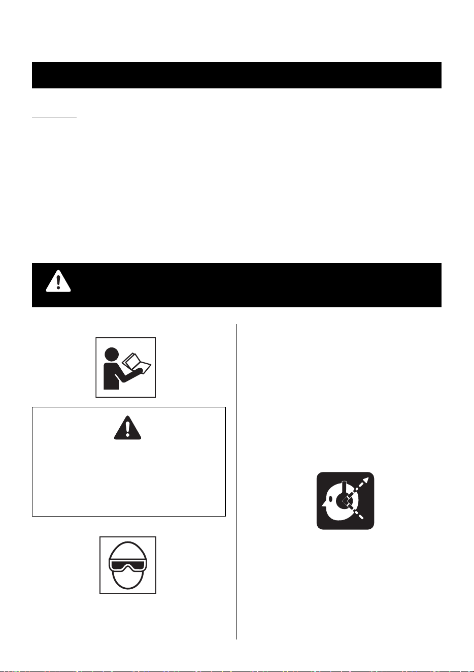
1. WEAR SAFETY GLASSES OR GOGGLES
Danger to the eyes always exists due to the possibility of
dust being blown up by the exhausted air or of a fastener fly-
ing up due to the improper handling of the tool. For these
reasons, safety glasses or goggles shall always be worn
when operating the tool.
The employer and/or user must ensure that proper eye pro-
tection is worn. Eye protection equipment must conform to
the requirements of the American National Standards Insti-
tute, ANSI Z87.1 (Council Directive 89/686/EEC of 21 DEC.
1989) and provide both frontal and side protection.
The employer is responsible to enforce the use of eye pro-
tection equipment by the tool operator and all other person-
nel in the work area.
Non-side shielded spectacles and face shields alone do not
provide adequate protection.
2. EAR PROTECTION MAY BE REQUIRED IN SOME ENVI-
RONMENTS
As the working condition may include exposure to high noise
levels which can lead to hearing damage, the employer and
user should ensure that any necessary hearing protection is
provided and used by the operator and others in the work area.
ENGLISH
OPERATING AND MAINTENANCE MANUAL
BEFORE USING THIS TOOL, STUDY THIS MANUAL TO ENSURE SAFETY WARNING AND IN-
STRUCTIONS.
KEEP THESE INSTRUCTIONS WITH THE TOOL FOR FUTURE REFERENCE.
WARNING
READ ALL SAFETY WARNINGS AND ALL
INSTRUCTIONS.
Failure to follow the warnings and instructions
may result in death serious injury.
Save all warn-
ings and instructions for future reference.
WARNING
4
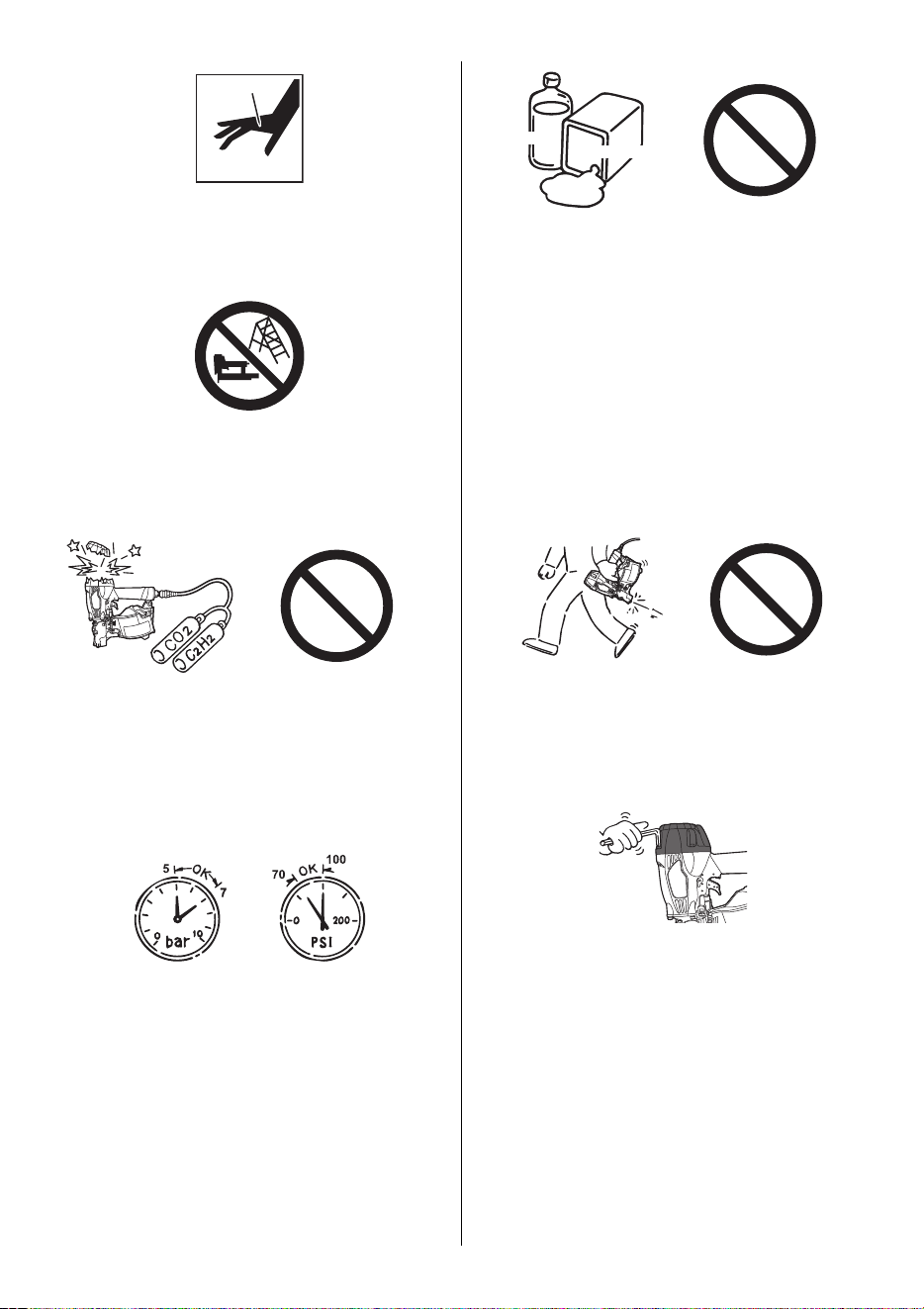
3. KEEP HANDS AND BODY AWAY FROM THE DIS-
CHARGE OUTLET
When loading and using the tool, never place a hand or any
part of body in fastener discharge area of the tool. It is very
dangerous to hit the hands or body by mistake.
4. DO NOT USE ON SCAFFOLDINGS AND LADDERS
Do not use on scaffoldings and ladders with fastener driving
tools equipped with contact actuation or continuous contact
actuation.
2. SAFETY WARNING
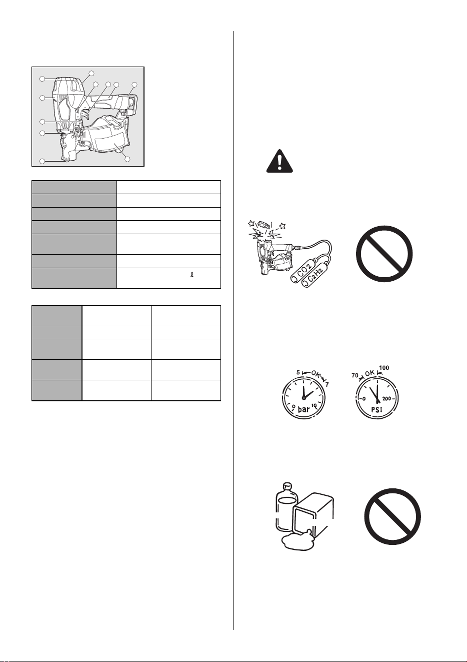
1. DO NOT USE ANY POWER SOURCE EXCEPT AN AIR
COMPRESSOR
The tool is designed to operate on compressed air. Do not
operate the tool on any other highpressure gas, combusti-
ble gases (e.g., oxygen, acetylene, etc.) since there is the
danger of an explosion. For this reason, absolutely do not
use anything other than an air compressor to operate the
tool.
2. OPERATE WITHIN THE PROPER AIR PRESSURE
RANGE
The tool is designed to operate within an air pressure range
of 70 to 100 p.s.i. (5 to 7 bar).
The pressure should be adjusted to the type of the work be-
ing fastened. The tool shall never be operated when the op-
erating pressure exceeds 120 p.s.i. (8.3 bar).
Never connect the tool to air pressure which potentially ex-
ceeds 200 p.s.i. (13.8 bar) as the tool can burst.
3. DO NOT OPERATE THE TOOL NEAR A FLAMMABLE
SUBSTANCE
Never operate the tool near a flammable substance (e.g.,
thinner, gasoline, etc.). Volatile fumes from these substanc-
es could be drawn into the compressor and compressed to-
gether with the air and this could result in an explosion.
4. NEVER USE THE TOOL IN AN EXPLOSIVE ATMOS-
PHERE
Sparks from the tool may ignite atmospheric gases, dust or
other combustible materials.
5. DO NOT USE A WRONG FITTINGS
The connector on the tool must not hold pressure when air
supply is disconnected. If a wrong fitting is used, the tool
can remain charged with air after disconnecting and thus
will be able to drive a fastener even after the air line is dis-
connected, possibly causing injury.
6. DISCONNECT THE AIR SUPPLY AND EMPTY THE
MAGAZINE WHEN THE TOOL IS NOT IN USE
Always disconnect the air supply from the tool and empty
the magazine when operation has been completed or sus-
pended, when unattended, moving to a different work area,
adjusting, disassembling, or repairing the tool, and when
clearing a jammed fastener.
7. INSPECT SCREW TIGHTNESS
Loose or improperly installed screws or bolts cause acci-
dents and tool damage when the tool is put into operation.
Inspect to confirm that all screws and bolts are tight and
properly installed prior to operating the tool.
Thinner
Gasoline
5
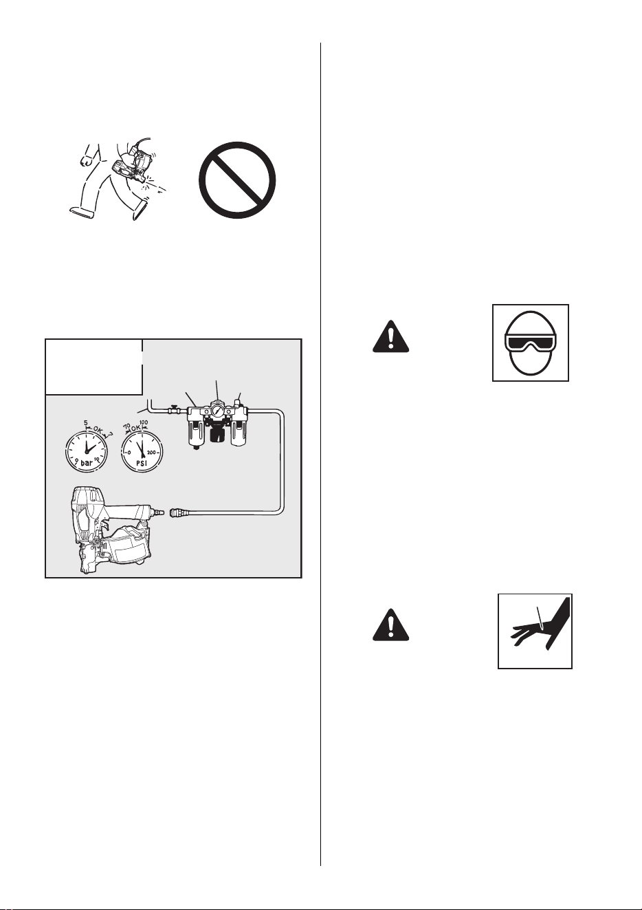
8. DO NOT TOUCH THE TRIGGER UNLESS YOU INTEND
TO DRIVE A FASTENER
Whenever the air supply is connected to the tool, never
touch the trigger unless you intend to drive a fastener into
the work. It is dangerous to walk around carrying the tool
with the trigger pulled, and this and similar actions should
be avoided.
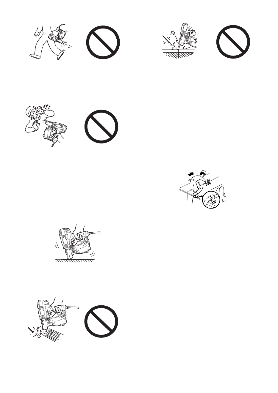
9. NEVER POINT THE DISCHARGE OUTLET TOWARD
YOURSELF AND OTHER PERSONNEL
If the discharge outlet is pointed toward people, serious ac-
cidents may be caused when misfiring. Be sure the dis-
charge outlet is not pointed toward people when connecting
and disconnecting the hose, loading and unloading the fas-
teners or similar operations.
10. USE SPECIFIED FASTENERS
(SEE PAGE 7)
The use of fasteners other than specified fasteners will
cause the tool malfunction. Be sure to use only specified
fasteners when operating the tool.
11. PLACE THE DISCHARGE OUTLET ON THE WORK SUR-
FACE PROPERLY
Failure to place the discharge outlet of the nose in a proper
manner can result in a fastener flying up and is extremely
dangerous.
12. DO NOT DRIVE FASTENERS CLOSE TO THE EDGE
AND CORNER OF THE WORK AND THIN MATERIAL
The workpiece is likely to split and the fastener could fly free
and hit someone.
13. DO NOT DRIVE FASTENERS ON TOP OF OTHER FAS-
TENERS
Driving fasteners on the top of other fasteners may cause
deflection fasteners which could cause injury.
14. REMOVING THE FASTENERS AFTER COMPLETING
OPERATION
If fasteners are left in the magazine after the completion of
operation, there is the danger of a serious accident occur-
ring prior to the resumption of operation, should the tool be
handled carelessly, or when connecting the air fitting. For
this reason, always remove all fasteners remaining in the
magazine after completion of the operation.
15. CHECK OPERATION OF THE CONTACT TRIP MECHA-
NISM FREQUENTLY INCASE OF USING A CONTACT
TRIP TYPETOOL
Do not use the tool if the trip is not working correctly as ac-
cidental driving of a fastener may result. Do not interfere
with the proper operation of the contact trip mechanism.
16. WHEN USING THE TOOL OUTSIDE OR ELEVATED
PLACE
When fastening roofs or similar slanted surface, start fas-
tening at the lower part and gradually work your way up.
Fastening backward is dangerous as you may lose your foot
place.
Secure the hose at a point close to the area you are going
to drive fasteners. Accidents may be caused due to the
hose being pulled inadvertently or getting caught.
17. NEVER USE THE TOOL IF ANY PORTION OF THE TOOL
CONTROLS (e.g., TRIGGER, CONTACT ARM) IS INOP-
ERABLE, DISCONNECTED, ALTERED OR NOT WOK-
ING PROPERLY
18. NEVER ACTUATE THE TOOL INTO FREE SPACE
This will avoid any hazard caused by free flying fasteners
and excessive strain of the tool.
19. ALWAYS ASSUME THAT THE TOOL CONTAINS FAS-
TENERS
20. RESPECT THE TOOL AS A WORKING IMPLEMENT
21. NO HORSEPLAY
22. NEVER LOAD THE TOOL WITH FASTENERS WHEN
ANY ONE OF THE OPERATING CONTROLS (e.g., TRIG-
GER, CONTACT ARM) IS ACTIVATED

6
23. WHEN DISPOSING THE MACHINE OR ITS PARTS, FOL-
LOW THE RELEVANT NATIONAL RULES
OBSERVE THE FOLLOWING GENERAL CAU-
TION IN ADDITION TO THE OTHER WARNINGS
CONTAINED IN THIS MANUAL
Always wear head protection, safety shoes and
mask when using the tool.
Do not use the tool as a hammer.
Always carry the tool by the grip, never carry the
tool by the air hose.
The tool must be used only for the purpose it was
designed.
Never remove, tamper with the operating controls
(e.g., TRIGGER, CONTACT ARM)
Keep the tool in a dry place out of reach of chil-
dren when not in use.
Do not use the tool without Safety Warning label.
Do not modify the tool from original design or
function without approval by MAX CO., LTD.
7
3. SPECIFICATIONS AND TECHNI-
CAL DATA
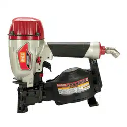
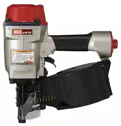
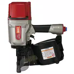
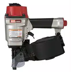
1. NAME OF PARTS
2. TOOL SPECIFICATIONS
3. FASTENER SPECIFICATIONS
TOOL AIR FITTINGS:
This tool uses a 1/4" N.P.T. male plug. The inside diameter should
be .28" (7 mm) or larger. The fitting must be capable of discharging
tool air pressure when disconnected from the air supply.
RECOMMENDED OPERATING PRESSURE:
70 to 100 p.s.i. (5 to 7 bar). Select the operating air pressure within
this range for best fastener performance.
DO NOT EXCEED 120 p.s.i. (8 bar).
4. TECHNICAL DATA
1 NOISE
A-weighted single-event sound power level
------ LWA, 1s, d 93.1 dB
A-weighted single-event emission sound pressure level at
work station
------ LpA, 1s, d 89.3 dB
These values are determined and documented in accordance
to EN12549 : 1999.
2 VIBRATION
Vibration characteristic value = 4.4 m/s
2
These values are determined and documented in accordance
to ISO 8662-11.
This value is a tool-related characteristic value and does not
represent the influence to the hand-arm-system when using
the tool. An influence to the hand-arm-system when using
the tool will for example depend on the gripping force, the
contact pressure force, the working direction, the adjustment
of mains supply, the workpiece, the workpiece support.
5. APPLICATIONS
Siding(Hardboard and Cement)
Sheathing
Fencing
Subflooring
Roof decking
Exterior deck
Exterior trim
Furring
Strapping
4. AIR SUPPLY AND CONNEC-
TIONS
Read section titled "SAFETY INSTRUCTIONS"
DO NOT USE ANY POWER SOURCE EXCEPT AN AIR COM-
PRESSOR
The tool is designed to operate on compressed air. Do not oper-
ate the tool on any other highpressure gas, combustible gases
(e.g., oxygen, acetylene, etc.) since there is the danger of an ex-
plosion. For this reason, absolutely do not use anything other
than an air compressor to operate the tool.
OPERATE WITHIN THE PROPER AIR PRESSURE RANGE
The tool designed to operate within an air pressure range of 70
to 100 p.s.i.. (5 to 7 bar)
The pressure should be adjusted to the type of the work being
fastened. The tool shall never be operated when the operating
pressure exceeds 120 p.s.i.. (8 bar)
DO NOT OPERATE THE TOOL NEAR A FLAMMABLE SUB-
STANCE
Never operate the tool near a flammable substance (e.g., thinner,
gasoline, etc.). Volatile fumes from these substances could be
drawn into the compressor and compressed together with the air
and this could result in an explosion.
1 Frame
2 Cylinder Cap
3 Contact Arm
4 Nose
5 Magazine
6 Trigger
7 Grip
8 Exhaust Port
9 Trigger Lock Dial
0 Adjustment Dial
a Hook
HEIGHT 11-7/8" (302 mm)
WIDTH 5" (127 mm)
LENGTH 10-7/8" (275 mm)
WEIGHT 5.2 lbs.(2.4 kg)
RECOMMENDED
OPERATING PRESSURE
70 to 100 p.s.i.
(5 to 7 bar)
LOADING CAPACITY 400 Nails
AIR CONSUMPTION
0.05 ft
3
at 100 p.s.i. (1.55 at 7 bar)
operating pressure
Collation type 15 degree flat wire
welded coil nails
15 degree flat plastic
collated coil nails
Shank type Smooth Screw Ring Smooth Screw Ring
Nail length 1-1/2" to 2-1/2"
(38 mm to 65 mm)
1-1/4" to 2-1/2"
(32 mm to 65 mm)
Shank diame-
ter
.083" to .099"
(2.1 mm to 2.5 mm)
.083" to .099"
(2.1 mm to 2.5 mm)
Head diameter .197" to .236"
(5.0 mm to 6.0 mm)
.197" to .236"
(5.0 mm to 6.0 mm)
5
9
6
2
7
4
1
3
8
10
11
WARNING
Thinner
Gasoline
8
DO NOT USE A WRONG FITTINGS
The connector on the tool must not hold pressure when air supply
is disconnected. If a wrong fitting is used, the tool can remain
charged with air after disconnecting and thus will be able to drive
a fastener even after the air line is disconnected, possibly caus-
ing injury.
DISCONNECT THE AIR SUPPLY AND EMPTY THE MAGAZINE
WHEN THE TOOL IS NOT IN USE
Always disconnect the air supply from the tool and empty the
magazine when operation has been completed or suspended,
when unattended, moving to a different work area, adjusting, dis-
assembling, or repairing the tool, and when clearing a jammed
fastener.
FITTINGS: Install a male plug on the tool which is free flowing
and which will release air pressure from the tool when discon-
nected from the supply source.
HOSES: The hose has a min. ID of 1/4" (6 mm) and a max.length
of no more than 17' (5 meters) from the 3-piece airset and
98' (30 meters) from the air compressor.
The supply hose should contain a fitting that will provide "quick
disconnecting" from the male plug on the tool.
SUPPLY SOURCE: Use only clean regulated compressed air as
a power source for the tool.
3-PIECE AIRSET (Air filter, Regulator, Oiler):
Refer to TOOL SPECIFICATIONS for setting the correct operat-
ing pressure for the tool.
NOTICE:
A filter will help to get the best performance and minimum wear
from the tool because dirt and water in the air supply are major
causes of wear in the tool.
Frequent, but not excessive, lubrication is required for the best
performance. Oil added thru the air line connection will lubricate
the internal parts.
5. INSTRUCTIONS FOR OPERA-
TION
Read section titled "SAFETY INSTRUCTIONS".
1. BEFORE OPERATION
Check the following prior operation.
1 Wear Safety Glasses or Goggles.
2 Do not connect the air supply.
3 Inspect screw tightness.
4 Check operation of the contact arm & trigger if moving
smoothly.
5 Connect the air supply.
6 Check the air-leakage. (The Tool must not have the air-
leakage.)
7 Hold the Tool with finger-off the trigger, then push the con-
tact arm against the work-piece. (The tool must not oper-
ate.)
8 Hold the Tool with contact arm free from work-piece and pull
the trigger. (The Tool must not operate.)
9 Disconnect the air supply.
2. OPERATION
Wear safety glasses or goggles danger to the eyes always exists
due to the possibility of dust being blown up by the exhausted air
or of a fastener flying up due to the improper handling of the tool.
For these reasons, safety glasses or goggles shall always be
worn when operating the tool.
The employer and/or user must ensure that proper eye protection
is worn. Eye protection equipment must conform to the require-
ments of the American National Standards Institute, ANSI Z87.1
(Council Directive 89/686/EEC of 21 DEC. 1989) and provide
both frontal and side protection.
The employer is responsible to enforce the use of eye protection
equipment by the tool operator and all other personnel in the work
area.
Non-side shielded spectacles and face shields alone do not pro-
vide adequate protection.
Keep hands and body away from the discharge outlet when driv-
ing the fasteners because of dangerous of hitting the hands or
body by mistake.
[AIR SUPPLY & CONNECTIONS]
Air filter
Air hose
Regulator
3-piece airset
Used at 70 to 100 p.s.i. (5 to 7 bar)
Air compressor
Oiler
WARNING
WARNING
9
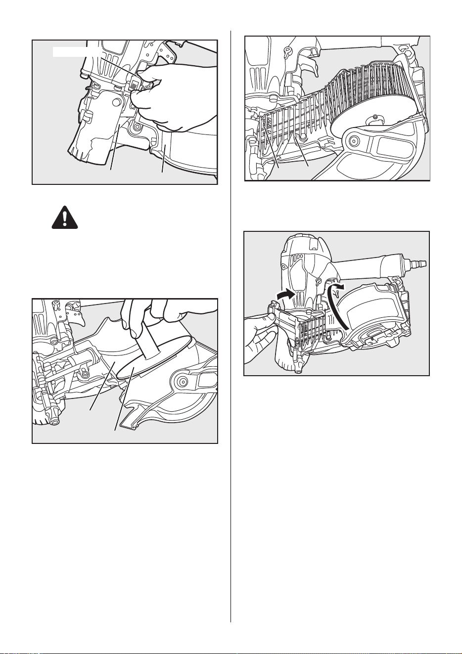
NAIL LOADING
ALWAYS disconnect air supply before nail loading.
1 Open the magazine:
Take hold of the door and of the door latch with your fingers.
Pull up the door latch and swing the door open. Swing the
magazine cover open.
2 Check adjustment:
The nail support can be moved up and down to four set-
tings. The nail support moves down by turning it counter-
clockwise and moves up by turning it clockwise. The nail
support should be adjusted correctly to the position as fol-
lows;
2-1/4" to 2-1/2" (57 to 65 mm) nails - use bottom step
2" (50 mm)nails - use second step
1-5/8" to 1-3/4" (40 to 45 mm) nails - use third step
1-1/4" to 1-1/2" (32 to 38 mm) nails - use top step
3 Nail loading:
Place a coil of nails over the post in the Magazine. Uncoil
enough nails to reach the Feed Pawl, and place the second
nail between the teeth on the Feed Pawl. The nail heads fit
in slot on nose.
4 Swing Cover closed.
5 Close the Door.
Check that latch engages. (If it does not engage, check that
the nail heads are in the slot on the Nose).
TEST OPERATION
1 Adjust the air pressure at 70 p.s.i. (5 bar) and connect the
air supply.
2 Without touching the Trigger, depress the Contact Arm
against the work-piece.
Pull the Trigger. (The tool must fire the fastener.)
3 With the tool off the work-piece, pull the Trigger.
Then depress the Contact Arm against the work-piece.
(The tool must fire the fastener.)
4 Adjust the air pressure as much as the lowest possible ac-
cording to the diameters and length of fastener and the
hardness of work-piece.
Magazine cover
Door
Door latch
WARNING
Magazine
Nail support
Feed pawl
Nail
10
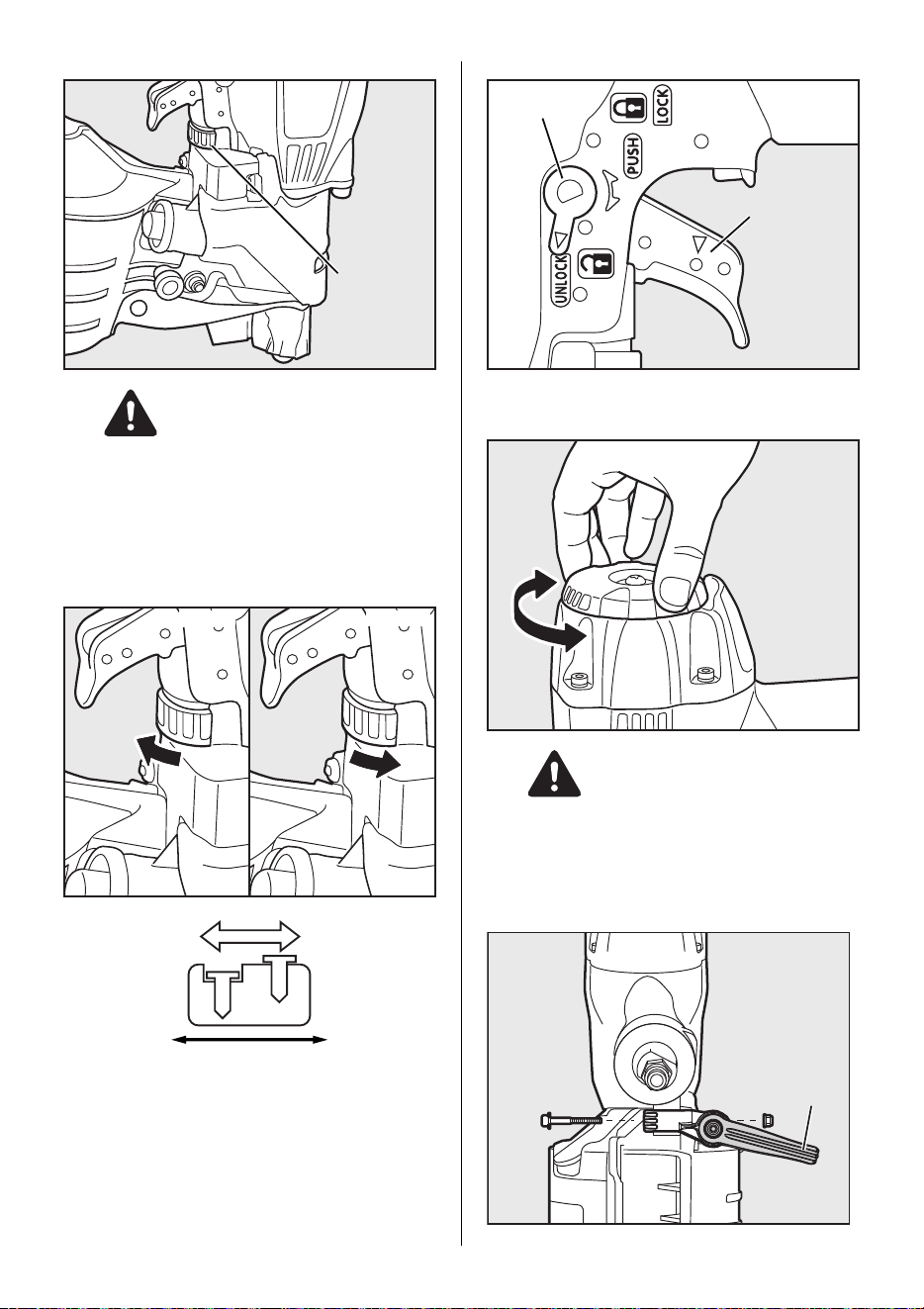
DRIVING DEPTH ADJUSTMENT DIAL
ALWAYS disconnect air supply before Adjust-
ment dial.
1 With air pressure set, drive nails into a representative mate-
rial sample to determine if adjustment is necessary.
2 If adjustment is required, disconnect air supply.
3 Refer to the mark on the Contact Arm area for direction to
turn the Adjustment dial.
4 Reconnect air supply.
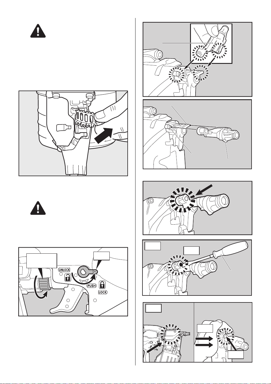
TRIGGER LOCK MECHANISM
The tool is equipped with a trigger lock mechanism. Push and rotate
the Trigger Lock Dial to the trigger free position before driving nails.
DIRECTIONAL EXHAUST COVER
ALWAYS disconnect air supply before rotating
the exhaust cover.
Direction of the exhaust air is changeable by rotating exhaust
cover by hand.
CHANGING THE HOOK DIRECTION
Adjustment dial
WARNING
Deeper
Shallower
Deeper Shallower
Trigger
Trigger lock dial
WARNING
Hook
11
ALWAYS disconnect air supply before changing
the hook direction.
The hook can be directed in the two direction. Re-
move the hexagon socket cap screw with hexagon
wrench, change the direction, and then, put back the
bolt to reassemble.
HOW TO REMOVE USED PLASTIC SHEET COLLATION
As nails are driven the plastic sheet will feed out of the tool. When
two inches or more has been fed out it can be torn away by pull-
ing against the tear edge in the nose.
HOW TO REATTACH THE REMOVABLE "CONTACT NOSE".
ALWAYS disconnect air supply before reassem-
bling the contact nose.
1 Lock the Trigger and turn the depth adjust dial to the shal-
lowest position.
2 Align the Contact Nose to the parts pointed by the arrows.
3
With a Flathead screwdriver (see A) or manually (see B),push
the Contact Nose at the place indicated below until it clicks.
WARNING
WARNING
shallowest
position
lock
Contact Nose
Contact Arm
Connection points
Contact Nose
Push here until it
clicks.
Push
A
Flathead
screwdriver
B
Push
Press
Keep pressing it and
push the Contact
Nose until it clicks.
Press here with
your palm.
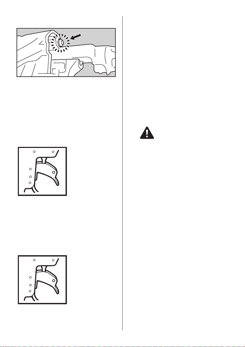
12
The tip of the rod must be seen like this after the reassembly is
done.
If not, try again from step 2.
MODEL IDENTIFICATION
CONTACT TRIP WITH ANTI-DOUBLE FIRE MECHANISM
(US patent 5597106, UK patent 2286790)
The common operating procedure on "Contact Trip" tools is for the
operator to contact the work to actuate the trip mechanism while
keeping the trigger pulled, thus driving a fastener each time the work
is contacted. This will allow rapid fastener placement on many jobs,
such as sheathing, decking and pallet assembly.All pneumatic tools
are subject to recoil when driving fasteners. The tool may bounce, re-
leasing the trip, and if unintentionally allowed to recontact the work
surface with the trigger still actuated (finger still holding trigger
pulled) an unwanted second fastener will be driven.
CONTACT TRIP WITH ANTI-DOUBLE FIRE MECHANISM
Identified by RED TRIGGER.
CONTACT FIRE OPERATION
For contact fire operation, hold the Trigger and depress the Con-
tact Arm against the work surface.
SINGLE FIRE OPERATION (ANTI-DOUBLE FIRE MECHA-
NISM)
For single fire operation, depress the Contact Arm against the
work surface and pull the Trigger.
Tool cannot fire a second nail until the Trigger is released and
tool can cycle.
SEQUENTIAL TRIP
Identified by ORANGE TRIGGER.
CONTACT TRIP WITH ANTI-DOUBLE FIRE MECHANISM
(Optional kit)
(US patent 5597106, UK patent 2286790)
The common operating procedure on "Contact Trip" tools is for
the operator to contact the work to actuate the trip mechanism
while keeping the trigger pulled, thus driving a fastener each time
the work is contacted. This will allow rapid fastener placement on
many jobs, such as sheathing, decking and pallet assembly. All
pneumatic tools are subject to recoil when driving fasteners. The
tool may bounce, releasing the trip,and if unintentionally allowed
to recontact the work surface with the trigger still actuated (finger
still holding trigger pulled) an unwanted second fastener will be
driven.
6. MAINTAIN FOR PERFORMANCE
1 DO NOT FIRE THE NAILER WHEN IT IS EMPTY
2 USE A 3-PIECE AIRSET
Failure to use a 3-piece airset allows the moisture and dirt inside
compressor to pass into the tool directly. This causes rust and
wear, and results in a poor operating performance. The hose
length between airset and tool should be no longer than 5 m since
a longer length results in a reduction in air pressure.
3 USE RECOMMENDED OIL
The velocite or turbine oil should be used to lubricate the tool.
Upon completion of operations, place 2 or 3 drops of oil into the
Air Plug inlet with the jet oiler. (Recommended Oil : ISO VG32)
4 INSPECT AND MAINTAIN DAILY OR BEFORE OPERA-
TION
Disconnect air supply and empty the Magazine when inspect-
ing or maintaining the tool.
(1) Drain air line filter and compressor
(2) Keep lubricator filled in air 3-pieces set
(3) Clean filter element of air 3-pieces set
(4) Tighten all screws
(5) Keep Contact Arm moving smoothly
7. STORING
1 When not in use for an extended period, apply a thin coat of
the lubricant to the steel parts to avoid rust.
2 Do not store the tool in a cold weather environment. Keep
the tool in a warm area.
3 When not in use, the tool should be stored in a warm and
dry place. Keep out of reach of children.
4 All quality tools will eventually require servicing or replace-
ment of parts because of wear from the normal use.
8. TROUBLE SHOOTING/REPAIRS
The troubleshooting and/or repairs shall be carried out only by
the MAX CO., LTD. authorised distributors or by other specialists.
WARNING

The content of this manual might be changed without notice for improvement.
Le contenu de ce manuel est sujet a modification sans preavis a des fins d'amelioration.
El contenido de este manual puede ser cambiado sin noticia previa para mejoramiento.
The specifications and design of the products in this manual will be subject to change without
advance notice due to our continuous efforts to improve the quality of our products.
Les caracteristiques et la conception des produits mentionnes dans ce manuel sont sujettes a
des modifications sans preavis en raison de nos efforts continus pour ameliorer la qualite de nos
produits.
Las caracteristicas y la concepcion de los productos mencionados en este manual estan sujetas
a modificaciones sin preaviso debido a nuestros esfuerzos continuos para mejorar la calidad de
nuestros productos.
4100367
160511-00/02
257 East 2nd Street
Mineola, NY 11501, U.S.A.
TEL: 1-800-223-4293
FAX: (516)741-3272
www.maxusacorp.com (USA Site)
wis.max-ltd.co.jp/int/ (GLOBAL Site)