© 2025 GeoVision, Inc. All rights reserved.
Under the copyright laws, this manual may not be copied, in whole or in part,
without the written consent of GeoVision.
Every effort has been made to ensure that the information in this manual is
accurate. GeoVision, Inc. makes no expressed or implied warranty of any kind
and assumes no responsibility for errors or omissions. No liability is assumed
for incidental or consequential damages arising from the use of the information
or products contained herein. Features and specifications are subject to
change without notice.
GeoVision, Inc.
9F, No. 246, Sec. 1, Neihu Rd.,
Neihu District, Taipei, Taiwan
Tel: +886-2-8797-8377
Fax: +886-2-8797-8335
http://www.geovision.com.tw
Trademarks used in this manual: GeoVision, the GeoVision logo and GV
series products are trademarks of GeoVision, Inc. Windows is the registered
trademark of Microsoft Corporation.
August 2025
Scan the following QR codes for product warranty and technical support
policy:
[Warranty] [Technical Support Policy]
i
Preface
Welcome to the GV-IP Decoder Box and GV-IP Display User’s Manual.
This Manual is designed for the following models:
Product Category
Model
GV-IP Decoder Box series
GV-IP Decoder Box Lite
GV-IP Decoder Box Mini
GV-IP Decoder Box Optimal
GV-IP Decoder Box Plus
GV-IP Decoder Box Ultra
GV-Pad Mini
GV-Pad Mini
GV-IP Display series
GV-IP Display 101
GV-IP Display 116
The terms HDMI, HDMI High-Definition Multimedia Interface, HDMI trade dress and the HDMI Logos are
trademarks or registered trademarks of HDMI Licensing Administrator, Inc.
Important Notice
GV-IP Decoder Box Mini / Optimal / Ultra can only accept one power source, either a PoE
power supply or a DC power adapter. Connecting two power sources simultaneously can
damage the device.
ii
Creating GV-IP Device’s Login
Credentials
When purchasing new GV-IP devices, or after resetting them, you need to create a login
username and password for these devices before they can be accessed by other software /
hardware.
1. Download and install GV-IP Device Utility from GeoVision’s website.
2. Once started, the utility will automatically search for GV-IP devices connected to the
same LAN.
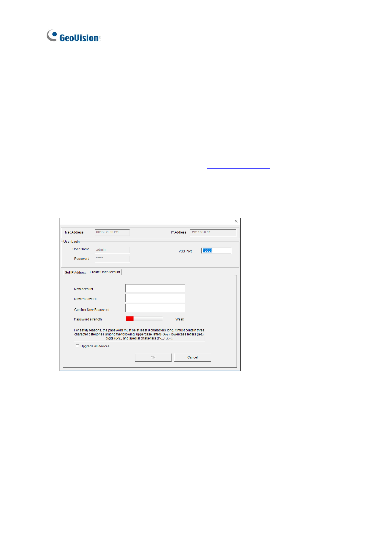
3. Double-click on a device in the list. This dialog box appears.
4. Click the Create User Account tab and type a username and password. The password
must meet the password strength required.
5. Optionally, click Upgrade all devices to apply the created username and password to all
devices which also don’t have any login credentials.

iii
Contents
Preface i
Important Notice ............................................................................................................... i
Creating GV-IP Device’s Login Credentials .................................................................... ii
Contents ...........................................................................................................................iii
Chapter 1 Introduction .................................................................................................. 1
1.1 GV-IP Decoder Box Lite .................................................................................. 1
1.1.1 Features .............................................................................................. 2
1.2 GV-IP Decoder Box Mini .................................................................................. 3
1.2.1 Features .............................................................................................. 4
1.3 GV-IP Decoder Box Optimal ............................................................................ 5
1.3.1 Features .............................................................................................. 6
1.4 GV-IP Decoder Box Plus ................................................................................. 7
1.4.1 Features .............................................................................................. 8
1.5 GV-IP Decoder Box Ultra ................................................................................. 9
1.5.1 Features .............................................................................................10
1.6 GV-Pad Mini ................................................................................................... 11
1.6.1 Features .............................................................................................12
1.7 GV-IP Display 101 ..........................................................................................13
1.7.1 Features .............................................................................................14
1.8 GV-IP Display 116 ..........................................................................................15
1.8.1 Features .............................................................................................16
1.9 Compatible Devices .......................................................................................17
1.10 Packing List ..................................................................................................19
1.11 Optional Accessories ....................................................................................20
1.11 Overview ......................................................................................................21
1.11.1 GV-IP Decoder Box Series ...............................................................21
1.11.2 GV-Pad Mini / GV-IP Display 101 / GV-IP Display 116 ......................29
1.11.3 GV-IR Remote Control ......................................................................31
Chapter 2 Getting Started ............................................................................................33
2.1 Installing GV-IP Decoder Box .........................................................................33
2.2 Connecting GV-IP Decoder Box Series ..........................................................34
2.3 Connecting GV-Pad Mini / GV-IP Display 101 / 116 ........................................36
2.4 The Main Screen ............................................................................................37
2.5 Setting Up the Network ..................................................................................38
2.6 Adding IP Devices to Live View Grid ..............................................................40

iv
2.6.1 Adding IP Devices through Automatic Search ....................................40
2.6.2 Adding IP Devices Manually ...............................................................44
2.7 Adding IP Devices Using GV-IP Device Utility ................................................46
2.7.1 Adding GV-IP Devices ........................................................................46
2.7.2 Adding Third-party Devices ................................................................49
Chapter 3 Accessing Live View ...................................................................................51
3.1 Live View ........................................................................................................51
3.2 Capturing Snapshots ......................................................................................56
3.3 Fisheye Dewarping .........................................................................................57
3.4 Controlling PTZ and Speed Dome Cameras with GV-Joystick V2 ..................59
Chapter 4 System Settings ..........................................................................................60
4.1 System ...........................................................................................................61
4.2 Network ..........................................................................................................62
4.3 Date & Time ...................................................................................................62
4.4 Account ..........................................................................................................63
4.5 Display ...........................................................................................................64
4.6 Camera ..........................................................................................................65
Chapter 5 Advanced Applications ...............................................................................66
5.1 Upgrading the Firmware .................................................................................66
5.1.1 Upgrading Firmware through a Storage Device ..................................66
5.1.2 Upgrading Firmware through GV-IP Device Utility ..............................67
5.2 Restoring Default Settings ..............................................................................68
Chapter 6 Integration to GV-Software .........................................................................70
6.1 Connecting to GV-VMS ..................................................................................71
6.2 Connecting to GV-Control Center / GV-Edge Recording Manager ..................73
6.2.1 Decoder Box Display through Video Wall ...........................................73
6.3 Dynamic Alerts via Control Center E-Map ..............................................78
Introduction
1
1
Chapter 1 Introduction
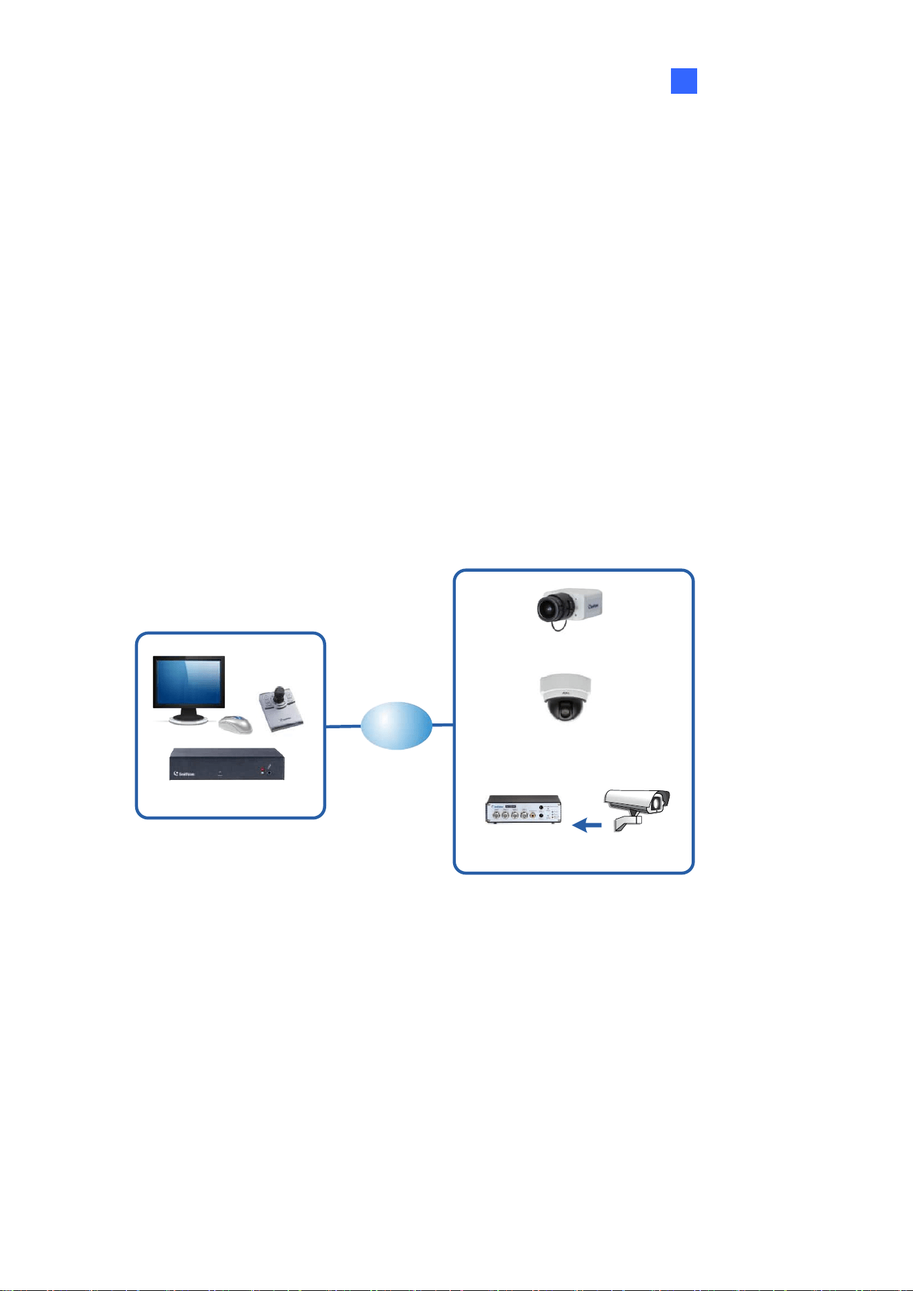
1.1 GV-IP Decoder Box Lite
GV-IP Decoder Box Lite can decode IP streams from GeoVision and third-party IP devices. It
connects cameras and a monitor for video display in single or split screen divisions. It can
detect ONVIF IP devices on the same LAN automatically. Enjoy a cost-effective alternative to
conventional DVRs and PC-based video surveillance systems. With GV-IP Decoder Box Lite,
you can monitor channels, capture snapshots of critical moments, and pause a channel when
events occur. Additionally, GV-Joystick V2 can be installed to efficiently control any PTZ or
Speed Dome cameras connected to the GV-IP Decoder Box Lite.
GV-IP Decoder Box Lite
GV-IP Camera
3rd party IP cameras
(ONVIF)
Analog camera
LAN
GV-Video Server

2
1.1.1 Features
⚫ Decode video streams in H.264 codec at up to 30 fps
⚫ Decode up to 2-megapixel IP cameras
⚫ Decode up to 16 IP streams
⚫ Automatically search for ONVIF IP devices
⚫ Support for third-party IP cameras that adhere to ONVIF
⚫ Single View and Quad View in sequential display
⚫ Support for 10/100/1000 Ethernet over LAN
⚫ VGA or HDMI video output resolutions up to 1080p
⚫ Control PTZ and Speed Dome cameras using GV-Joystick V2
⚫ Remote firmware upgrade, IP address configuration, and addition of new channel
⚫ USB drive for firmware upgrade
Introduction
3
1
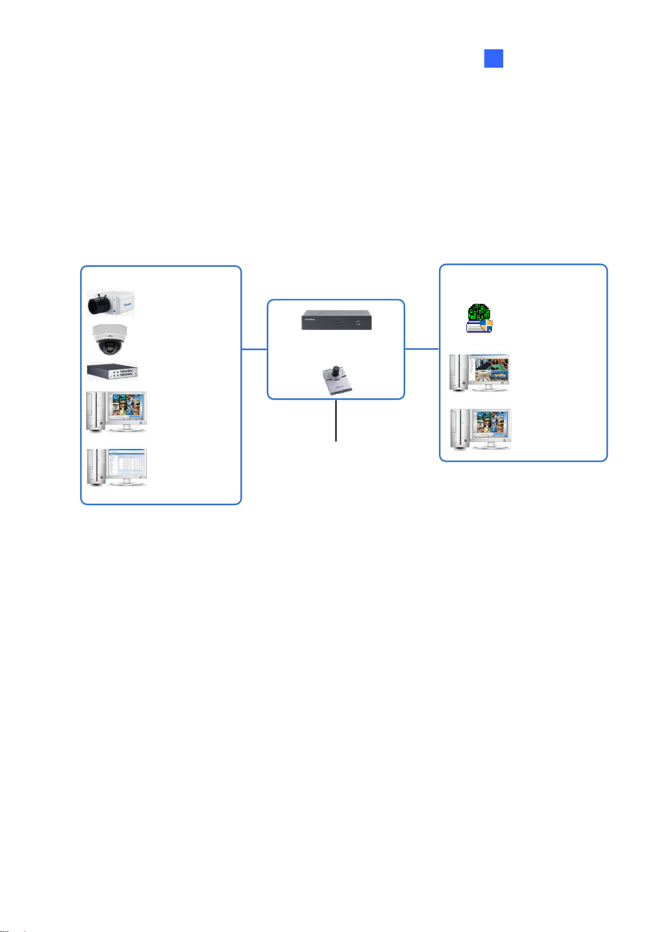
1.2 GV-IP Decoder Box Mini
GV-IP Decoder Box Mini can decode and loop up to 64 IP streams in a single division on an
HDMI monitor. It supports third-party IP cameras via RTSP or ONVIF and automatically
detects ONVIF-compliant cameras on the same LAN. Administrators can monitor channels,
capture snapshots of key moments, and pause live view during events. GV-Joystick V2 can
also be connected for PTZ or Speed Dome camera control.
GV-IP Decoder Box Mini
+
Display Monitor
HDMI
GV-IP Camera
3
rd
party IP Camera
(ONVIF)
GV-Video Server
GV-DVR/NVR/VMS
& GV-Mobile Server
GV-Video Gateway /
Recording Server
through GV-Mobile
Server
Video Source
Remote Live View Layout Edit
GV-IP Device Utility
GV-Control Center /
GV-Edge Recording
Manager
GV-VMS

4
1.2.1 Features
• Decode one IP channel
• Decode video streams in H.264 / H.265 codec at up to 60 fps
• Decode up to 8 MP resolution
• Auto-search for ONVIF IP devices
• Support for third-party IP cameras that adhere to RTSP or ONVIF
• Display of Matrix view through GV-Mobile Server
• Support for 10/100 Ethernet over LAN
• DC 12V / PoE (IEEE 802.3af)
• HDMI output display
• User interface controls using GV-IR Remote Control
• PTZ or Speed Dome camera control using GV-Joystick V2
• USB drive for snapshot storage and firmware upgrade
• Support for camera and layout assignment remotely from GV-VMS, GV-Control Center,
GV-Edge Recording Manager
• Support for 10 languages
Introduction
5
1
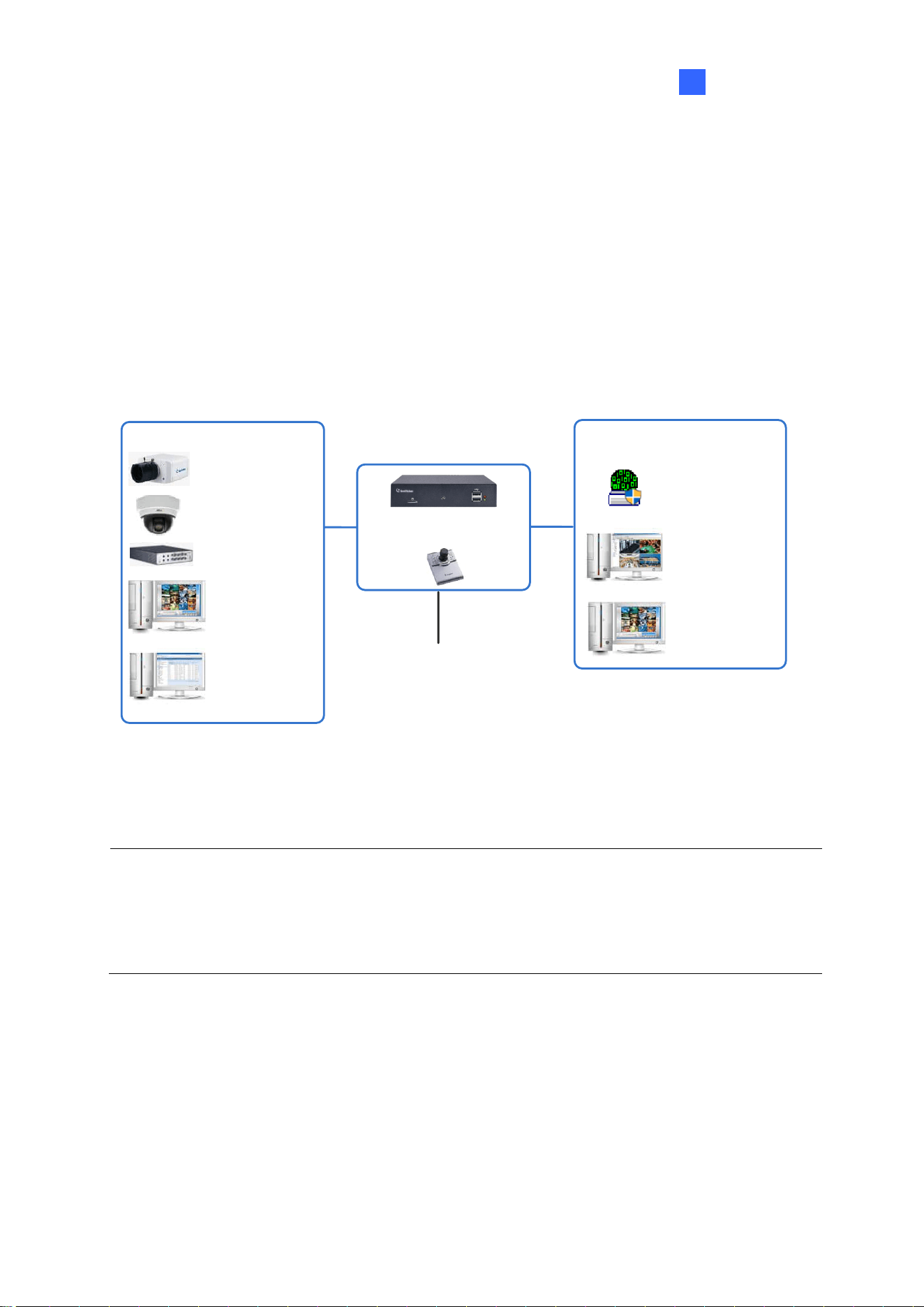
1.3 GV-IP Decoder Box Optimal
GV-IP Decoder Box Optimal can decode and loop up to 64 IP video streams in single, 4-, 6-,
8-, 9-, or 16-division views. It supports third-party IP cameras via RTSP or ONVIF and can
automatically detect ONVIF-compliant cameras on the same LAN. With both HDMI and VGA
outputs, it enables dual-monitor display, allowing live view channels to loop on the extended
screen for more effective surveillance. Administrators can monitor channels, capture
snapshots of critical moments, and pause a channel when events occur. GV-Joystick V2 can
also be connected for PTZ or Speed Dome camera control.
GV-IP Decoder Box Optimal
+
Display Monitor
HDMI / VGA
GV-IP Camera
3
rd
party IP Camera
(ONVIF)
GV-Video Server
GV-DVR/NVR/VMS
& GV-Mobile Server
GV-Video Gateway /
Recording Server
through GV-Mobile
Server
Video Source
Remote Live View Layout Edit
GV-IP Device Utility
GV-Control Center /
GV-Edge Recording
Manager
GV-VMS
Note: GV-VMS V17.4.8 / V18.3.3 or later, GV-Control Center V4.2.1 or later, GV-Edge
Recording Manager V2.2.8 or later support GV-IP Decoder Box Optimal to be assigned with
the desired camera channels of GV-VMS and GV-Control Center for remote display. See
details in Chapter 6 Integration to GV-Software.

6
1.3.1 Features
• Decode video streams in H.264 / H.265 codec at up to 60 fps (1-ch max.)
• Decode up to 8-megapixel IP cameras
• Decode up to 64 IP streams
• Automatically search for ONVIF IP devices
• Support for third-party IP cameras that adhere to RTSP or ONVIF
• Single, 4-Divsion, 6-Division, 8-Division, 9-Division, and 16-Division View
• Display of Matrix view through GV-Mobile Server
• Support for 10/100 Ethernet over LAN
• DC 12V / PoE (IEEE 802.3af)
• Dual monitor display for HDMI / VGA output
• Control the user interface using GV-IR Remote Control
• Control PTZ and Speed Dome cameras using GV-Joystick V2
• Remote firmware upgrade, IP address configuration, and addition of new channel
• Micro SD card and USB drive for snapshot storage and firmware upgrade
Introduction
7
1
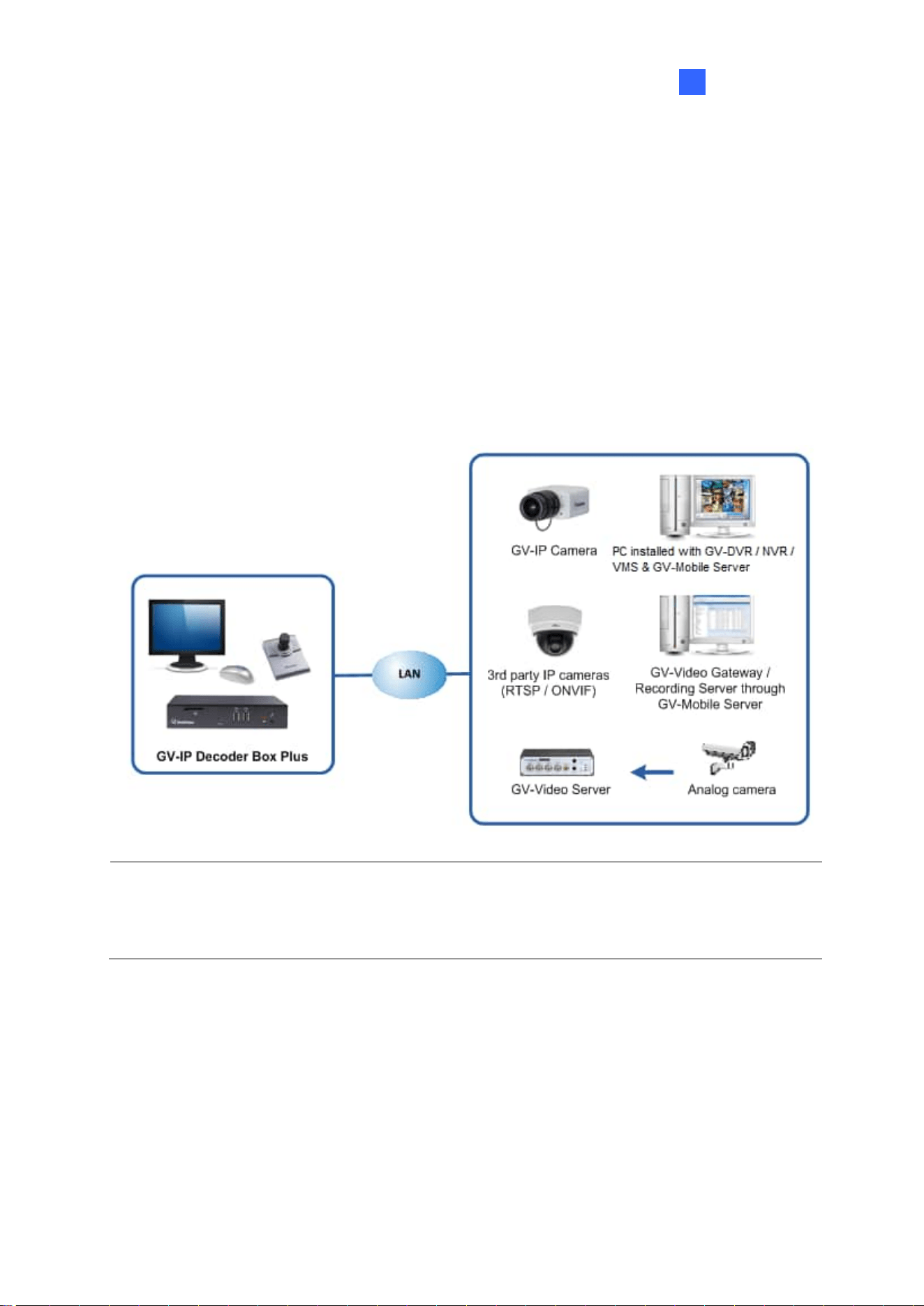
1.4 GV-IP Decoder Box Plus
GV-IP Decoder Box Plus can decode IP streams from GeoVision and third-party IP devices. It
connects cameras and a monitor for video display in single or split screen divisions. It
supports RTSP or ONVIF IP cameras and can detect ONVIF IP devices on the same LAN
automatically. Enjoy a cost-effective alternative to conventional DVRs and PC-based video
surveillance systems. With GV-IP Decoder Box Plus, you can monitor channels, capture
snapshots of critical moments, and pause a channel when events occur. Additionally,
GV-Joystick V2 can be installed to efficiently control any PTZ or Speed Dome cameras
connected to the GV-IP Decoder Box Plus.
Note: GV-VMS V17.4.0 supports GV-IP Decoder Box Plus to be assigned with the desired
camera channels of GV-VMS and GV-Control Center for remote display. See details in
Chapter 6 Integration to GV-Software.

8
1.4.1 Features
⚫ Decode video streams in H.264 codec at up to 30 fps
⚫ Decode up to 4-megapixel IP cameras
⚫ Decode up to 64 IP streams
⚫ Automatically search for ONVIF IP devices
⚫ Support for third-party IP cameras that adhere to RTSP or ONVIF
⚫ Support for fisheye dewarping in Single View and Grid 1 of Quad View
⚫ Single View, Quad View, and 9-Division View in sequential display
⚫ Display of Matrix view through GV-Mobile Server
⚫ Support for 10/100/1000 Ethernet over LAN
⚫ VGA or HDMI video output resolutions up to 1080p
⚫ Control PTZ and Speed Dome cameras using GV-Joystick V2
⚫ Remote firmware upgrade, IP address configuration, and addition of new channel
⚫ SD card slot and USB drive for snapshot storage and firmware upgrade
Introduction
9
1
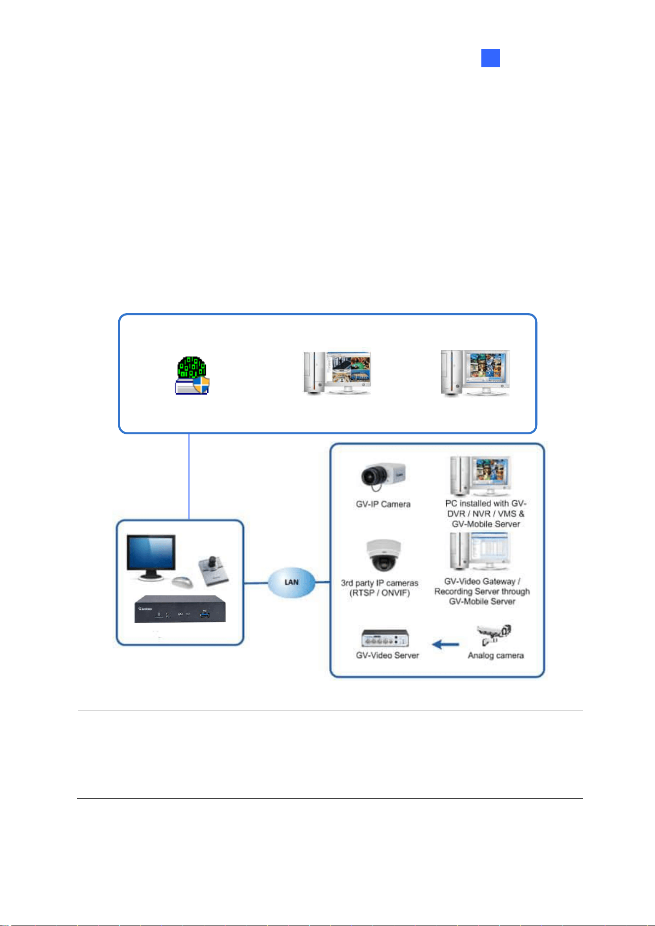
1.5 GV-IP Decoder Box Ultra
GV-IP Decoder Box Ultra can decode and loop up to 64 IP video streams in single, 4-, 6-, 8-,
and 9-division views. It supports third-party IP cameras via RTSP or ONVIF and can
automatically detect ONVIF-compliant cameras on the same LAN. As a cost-effective
alternative to traditional DVRs and PC-based video surveillance systems, it allows
administrators to monitor channels, capture snapshots of critical events, and pause channels
when needed. GV-Joystick V2 can also be connected for PTZ or Speed Dome camera
control.
PC installed with GV-
DVR / NVR / VMS &
GV-Mobile Server
GV-IP Decoder Box Ultra
Remote Live View Layout Edit
GV-IP Device Utility
GV-Control Center /
GV-Edge Recording Manager
GV-VMS
Note: GV-VMS V17.4.0 / V18.1.0 or later, GV-Control Center V3.8.0 / V4.2.0 or later,
GV-Edge Recording Manager V2.2.8 or later support GV-IP Decoder Box Ultra to be
assigned with the desired camera channels of GV-VMS and GV-Control Center for remote
display. See details in Chapter 6 Integration to GV-Software.

10
1.5.1 Features
⚫ Decode video streams in H.264 / H.265 codec at up to 30 fps
⚫ Decode up to 8-megapixel IP cameras
⚫ Decode up to 64 IP streams
⚫ Automatically search for ONVIF IP devices
⚫ Support for third-party IP cameras that adhere to RTSP or ONVIF
⚫ Support for Single, 4-Divsion, 6-Division, 8-Division, and 9-Division View
⚫ Display of Matrix view through GV-Mobile Server
⚫ Support for 10/100 Ethernet over LAN
⚫ DC 12V / PoE (IEEE 802.3af)
⚫ HDMI video output resolutions up to 4K
⚫ Control the user interface using GV-IR Remote Control
⚫ Control PTZ and Speed Dome cameras using GV-Joystick V2
⚫ Remote firmware upgrade, IP address configuration, and addition of new channel
⚫ Micro SD card and USB drive for snapshot storage and firmware upgrade
⚫ Support for camera and layout assignment remotely from GV-VMS, GV-Control Center,
or GV-Edge Recording Manager
⚫ Support for 10 languages
Introduction
11
1
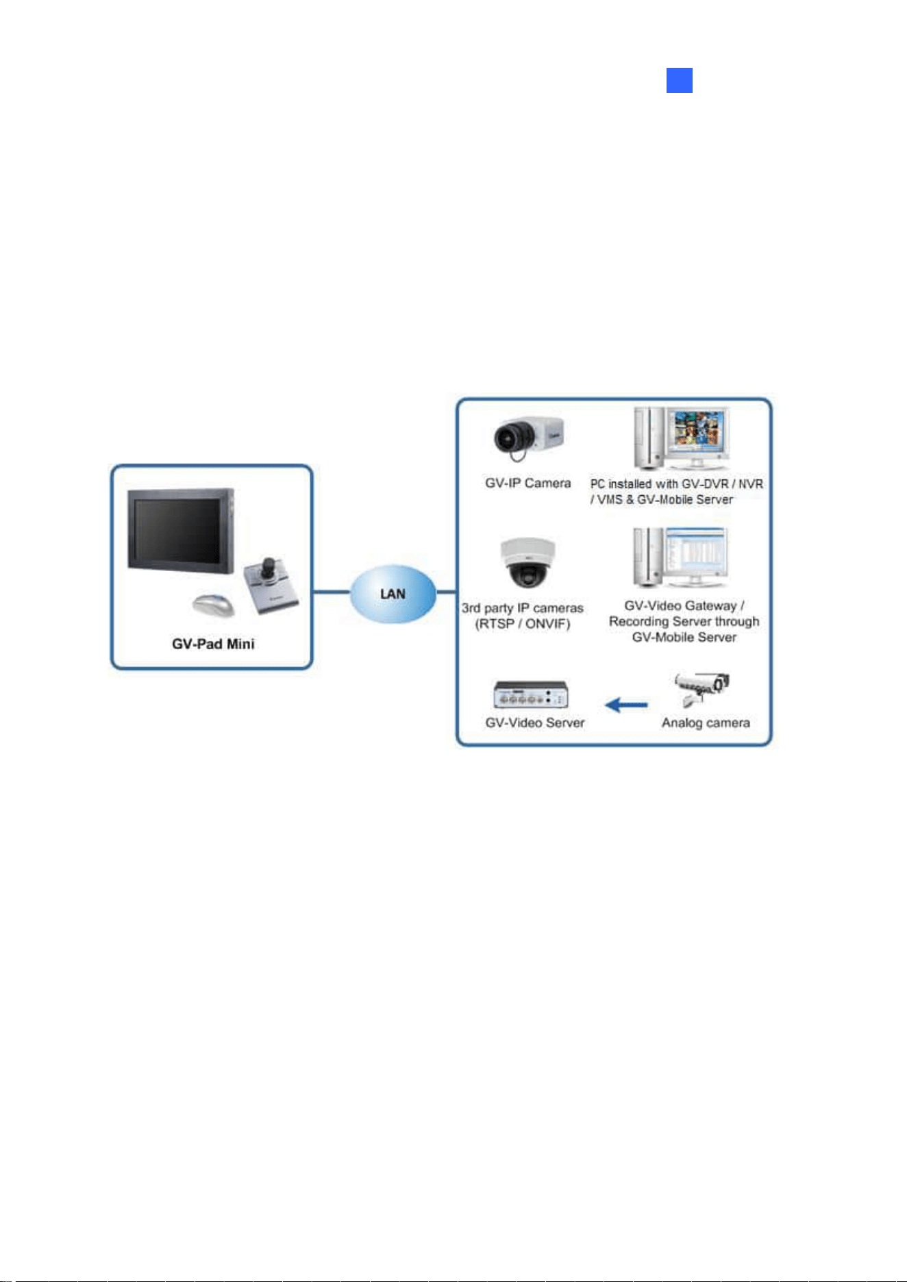
1.6 GV-Pad Mini
GV-Pad Mini is a panel device capable of decoding and displaying up to 64 IP cameras in
single or split screen divisions. It is light weighted and requires only a minimal amount of
installation. GV-Pad Mini allows you to monitor channels, capture snapshots of critical
moments, and pause a channel when specific events occur. In addition, GV-Joystick V2 can
be installed to effectively control GeoVision and third-party PTZ / Speed Dome cameras.

12
1.6.1 Features
⚫ Decode video streams in H.264 codec at up to 30 fps
⚫ Decode up to 4-megapixel IP cameras
⚫ Decode up to 64 IP streams
⚫ Automatically search for ONVIF IP devices
⚫ Support for third-party IP cameras that adhere to RTSP or ONVIF
⚫ Single View, Quad View, and 9-Division View in sequential display
⚫ Display of Matrix view through GV-Mobile Server
⚫ Support for 10/100/1000 Ethernet over LAN
⚫ Control PTZ and Speed Dome cameras using GV-Joystick V2
⚫ Micro SD card slot and USB drive for snapshot storage and firmware upgrade
Introduction
13
1
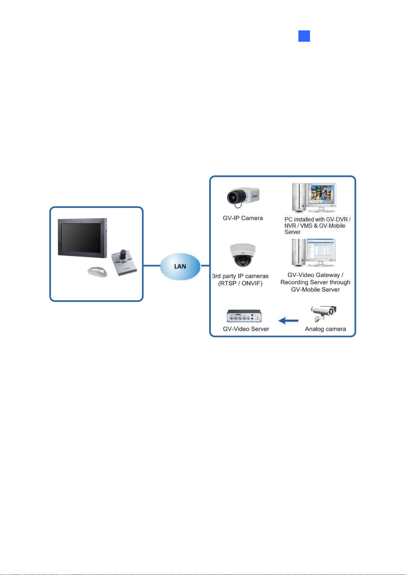
1.7 GV-IP Display 101
GV-IP Display 101 is a panel device capable of decoding and displaying up to 64 IP cameras
in single or split screen divisions. It is light weighted and requires only a minimal amount of
installation. GV-IP Display 101 allows you to monitor channels, capture snapshots of critical
moments, and pause a channel when events occur. In addition, GV-Joystick V2 can be
installed to effectively control any PTZ or Speed Dome cameras connected to the GV-IP
Display 101.
GV-IP Display 101

14
1.7.1 Features
⚫ Decode video streams in H.264 / H.265 codec at up to 30 fps
⚫ Decode up to 8-megapixel IP cameras
⚫ Decode up to 64 IP streams
⚫ Automatically search for ONVIF IP devices
⚫ Support for third-party IP cameras that adhere to RTSP or ONVIF
⚫ Single, 4-Divsion, 6-Division, 8-Division, and 9-Division View
⚫ Display of Matrix view through GV-Mobile Server
⚫ Support for 10/100 Ethernet over LAN
⚫ Control PTZ and Speed Dome cameras using GV-Joystick V2
⚫ Micro SD card slot and USB drive for snapshot storage and firmware upgrade
Introduction
15
1
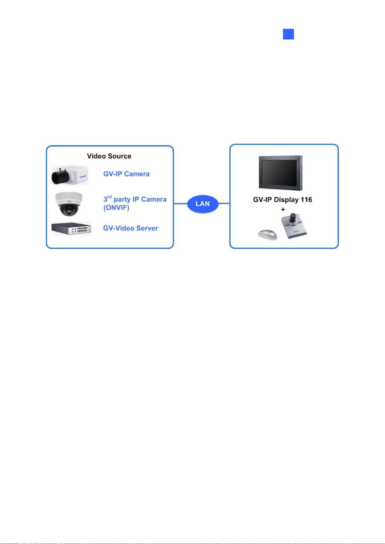
1.8 GV-IP Display 116
GV-IP Display 116 is a lightweight panel device designed for efficient IP camera monitoring. It
supports decoding and looping of up to 64 IP camera streams, with flexible viewing options
including single, 4-, 6-, 8-, and 9-division layouts. Minimal installation is required, making it
ideal for streamlined deployment.

16
1.8.1 Features
⚫ Decode video streams in H.264 / H.265 codec at up to 30 fps
⚫ Decode up to 8-megapixel IP cameras
⚫ Decode up to 64 IP streams
⚫ Automatically search for ONVIF IP devices
⚫ Support for third-party IP cameras that adhere to RTSP or ONVIF
⚫ Single, 4-Divsion, 6-Division, 8-Division, and 9-Division View
⚫ Display of Matrix view through GV-Mobile Server
⚫ Support for 10/100 Ethernet over LAN
⚫ Control PTZ and Speed Dome cameras using GV-Joystick V2
⚫ Micro SD card slot and USB drive for snapshot storage and firmware upgrade
⚫ Support for 10 languages

Introduction
17
1
1.9 Compatible Devices
The compatible devices for GV-IP Decoder Box series, GV-Pad Mini, and GV-IP Display
series vary according to different models.
GV-IP Decoder Box Mini / Optimal / Ultra / GV-IP Display 101 / GV-IP Display 116
1. GV-IP Camera and GV-Video Server
2. Third-party IP devices that support H.264 / H.265 and adhere to RTSP or ONVIF
3. GV-Mobile Server
4. HD DVR: UA-XVR and UA-XVL models (only for GV-IP Decoder Box Mini / Optimal)
To decode and display non-H.264 / H.265 IP cameras, analog cameras or GV-FER12203 /
12700, connect the cameras to GV-NVR / VMS and access them through GV-Mobile Server.

18
GV-IP Decoder Box Plus / GV-Pad Mini
1. GV-IP Camera and GV-Video Server using H.264 codec
2. Third-party IP devices that support H.264 and adhere to RTSP or ONVIF
3. GV-Mobile Server
To decode and display non-H.264 IP cameras or analog cameras, connect the cameras to
GV-DVR / NVR / VMS and access them through GV-Mobile Server.
GV-IP Decoder Box Lite
1. GV-IP Camera and GV-Video Server using H.264 codec
2. Third-party IP devices that support H.264 and adhere ONVIF
To decode and display analog cameras, connect the cameras to GV-IP Decoder Box Lite
through GV-Video Server.
Note:
1. GV-Mobile Server is an application that encodes up to 64 video channels and
subsequently allows GV-IP Decoder Box Mini / Optimal / Ultra / Plus / GV-Pad Mini /
GV-IP Display 101 / 116 to decode and display:
⚫ Analog cameras and IP cameras connected to GV-DVR / NVR / VMS
⚫ IP channels connected to GV-Recording Server / GV-Video Gateway
⚫ Third-party IP cameras through ONVIF
⚫ 4 matrix views
For details, see GV-Mobile Server User’s Manual.
2. Upgrade your GV-IP devices to the latest firmware version if you encounter any
connection problems.

Introduction
19
1
1.10 Packing List
GV-IP Decoder Box Lite
1. GV-IP Decoder Box Lite
2. AC/DC Adapter (12 V, 3 A, 36 W)
3. Power Cord
4. USB Mouse
5. Download Guide
6. Warranty Card
GV-IP Decoder Box Ultra
1. GV-IP Decoder Box Ultra
2. GV-IR Remote Control
3. Download Guide
4. Warranty Card
GV-IP Decoder Box Mini
1. GV-IP Decoder Box Mini
2. GV-IR Remote Control
3. Download Guide
4. Warranty Card
GV-Pad Mini
1. GV-Pad Mini
2. AC/DC Adapter (12 V, 3 A, 36 W)
3. Power Cord
4. USB Mouse
5. Download Guide
6. Warranty Card
GV-IP Decoder Box Optimal
1. GV-IP Decoder Box Optimal
2. GV-IR Remote Control
3. Download Guide
4. Warranty Card
GV-IP Display 101
1. GV-IP Display 101
2. AC/DC Adapter (12 V, 3 A, 36 W)
3. Power Cord
4. Download Guide
5. Warranty Card
GV-IP Decoder Box Plus
1. GV-IP Decoder Box Plus
2. AC/DC Adapter (12 V, 3 A, 36 W)
3. Power Cord
4. USB Mouse
5. Download Guide
6. Warranty Card
GV-IP Display 116
1. GV-IP Display 116
2. AC/DC Adapter (12 V, 3 A, 36 W)
3. Power Cord
4. Download Guide
5. Warranty Card

20
1.11 Optional Accessories
Optional Accessory
Details
GV-Joystick V2
GV-Joystick V2 facilitates focusing, zooming, panning,
and tilting of GeoVision and third-party PTZ or Speed
Dome cameras to GV-IP Decoder Box series / GV-Pad
Mini / GV-IP Display 101.
⚫ GV-Joystick V2
⚫ USB Type A to Type B Cable
⚫ RJ-45 Cable
⚫ Download Guide
GV-PoE Switch
GV-PoE Switch is designed to provide power along with
network connection for IP devices. GV-PoE Switch is
available in various models with different numbers and
types of ports.
HDMI Cable
Only available for GV-IP Decoder Box Mini / Optimal /
Ultra. Use the HDMI cable to connect the decoder box
with an HDMI monitor for high-quality image display.
Length: 150 cm (4.92 ft)
Version: 1.4a
Power Adapter
For GV-IP Decoder Box Mini / Optimal / Ultra, contact our
sales representatives for the countries and areas
supported.
Wall Mount Kit
The Wall Mount Kit is used to mount GV-IP Decoder Box
series to the wall.
⚫ L-type brackets x 2
⚫ Small screws x 4
Introduction
21
1
1.11 Overview
1.11.1 GV-IP Decoder Box Series
1.11.1.1 Front View
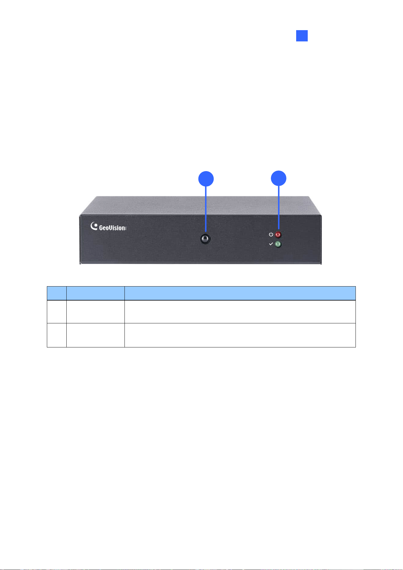
GV-IP Decoder Box Mini
1
2
No.
Name
Function
1
IR sensor
Receive signal from GV-IR Remote Control for controlling the user
interface at the maximum operation distance of 7 m (22.97 ft).
2
LED Indicators
The red LED indicates the power is supplied.
The green LED indicates the system is ready for use.
22
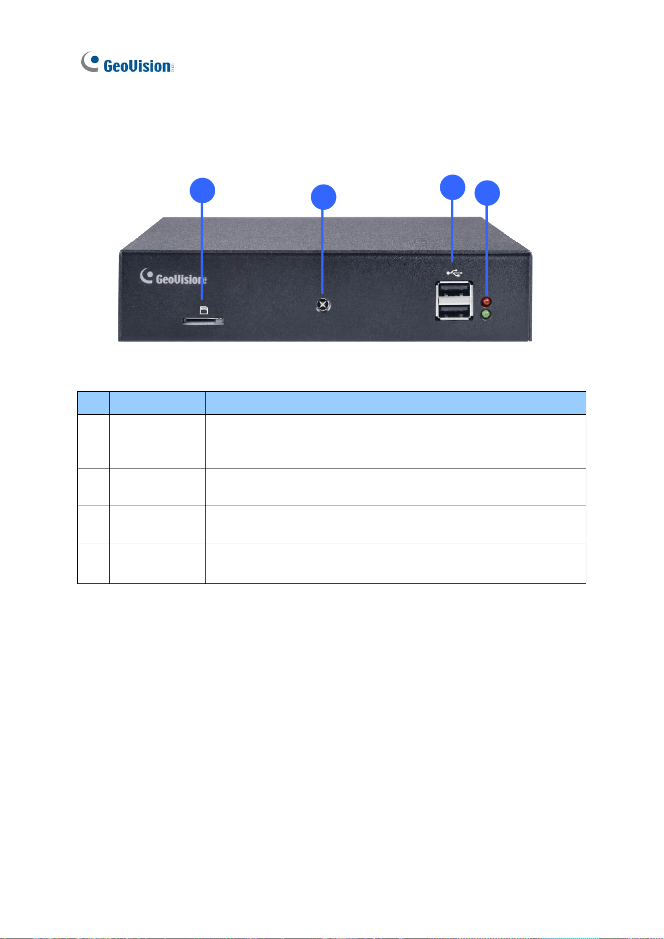
GV-IP Decoder Box Optimal
1
2
3
4
No.
Name
Function
1
Micro SD Card
Slot
Connect to a micro SD card for local storage of snapshots and
firmware upgrade.
2
IR sensor
Receive signal from GV-IR Remote Control for controlling the user
interface at the maximum operation distance of 7 m (22.97 ft).
3
USB 2.0
Connect to a GV-Joystick V2, USB mouse, or USB storage device
4
LED Indicators
The red LED indicates the power is supplied.
The green LED indicates the system is ready for use.
Introduction
23
1
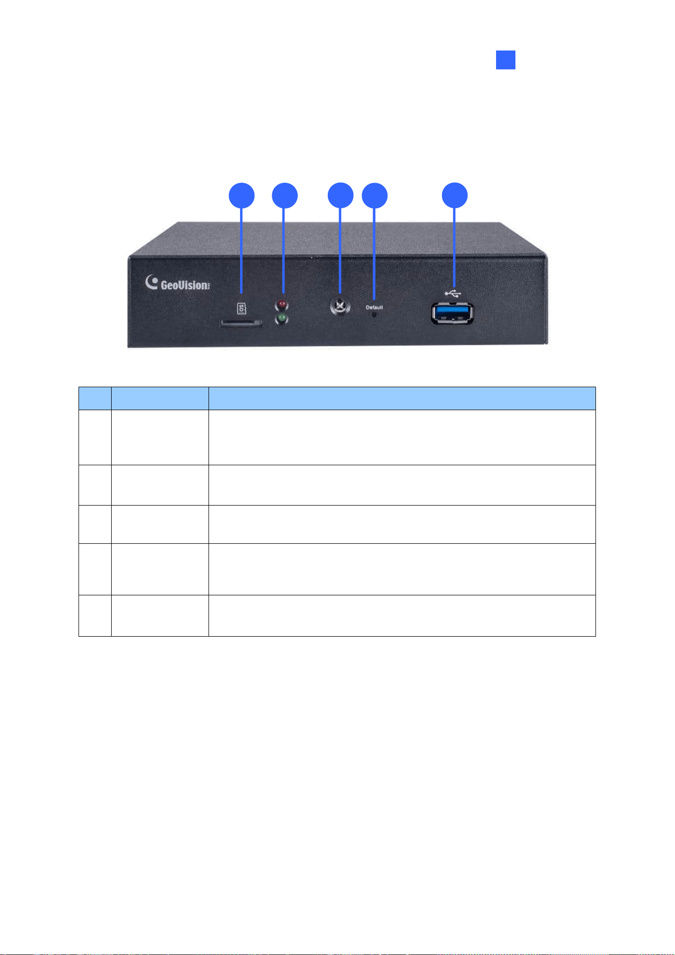
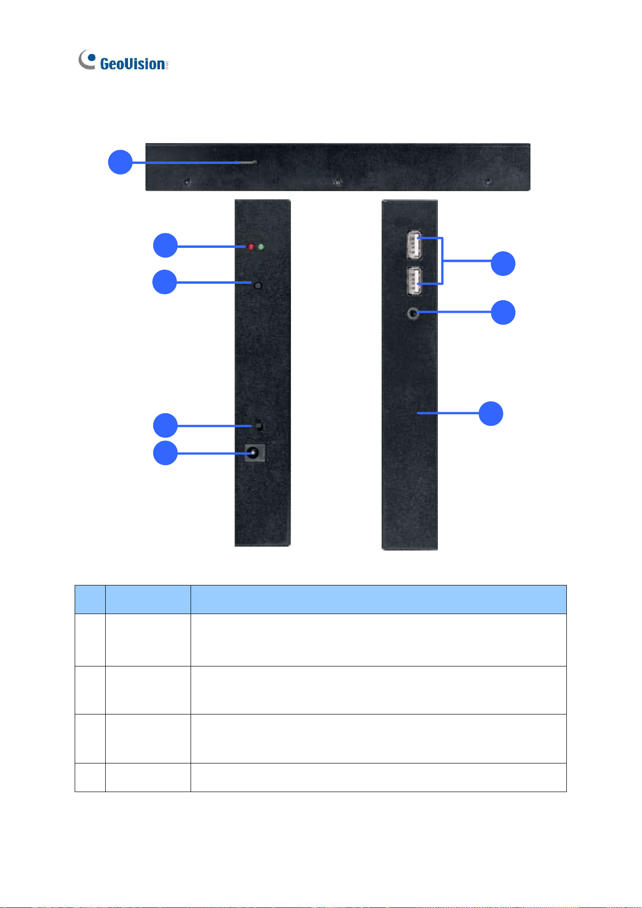
GV-IP Decoder Box Ultra
1
2
3
4
5
No.
Name
Function
1
Micro SD Card
Slot
Connect to a micro SD card for local storage of snapshots and
firmware upgrade.
2
LED Indicators
The red LED indicates the power is supplied.
The green LED indicates the system is ready for use.
3
IR sensor
Receive signal from GV-IR Remote Control for controlling the user
interface at the maximum operation distance of 7 m (22.97 ft).
4
Default
Reset the device to the default factory settings. Use a pin to press the
default button for about 10 seconds. The system will then reset and
reboot itself shortly. See 5.2 Restoring Default Settings.
5
USB 3.0
Connect to a GV-Joystick V2, USB mouse, or USB storage device
24
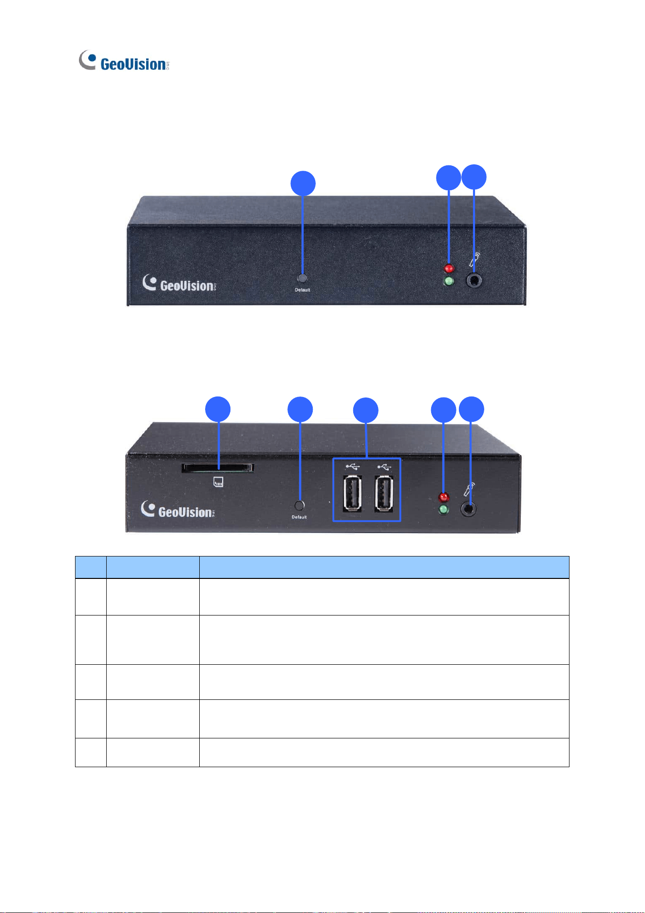
GV-IP Decoder Box Lite
4
2
5
GV-IP Decoder Box Plus
1
4
2
3
5
No.
Name
Function
1
SD Card Slot
Connect to a SD card for local storage of snapshots and firmware
upgrade. Only supported by GV-IP Decoder Box Plus.
2
Default
Reset the device to the default factory settings. Use a pin to press the
default button for about 10 seconds. The system will then reset and
reboot itself shortly. See 5.2 Restoring Default Settings.
3
USB
Connect to a GV-Joystick V2, USB mouse, or USB storage device.
Only supported by GV-IP Decoder Box Plus.
4
LED Indicators
The red LED indicates the power is supplied.
The green LED indicates the system is ready for use.
5
Audio In
Not functional.
Introduction
25
1
1.11.1.2 Rear View
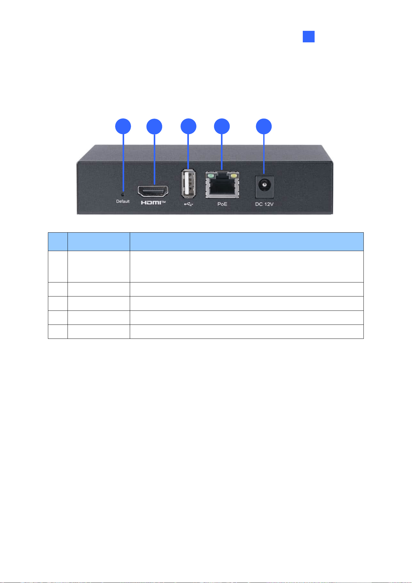
GV-IP Decoder Box Mini
1
2
3 4
5
No.
Name
Function
1
Default
Reset the device to the default factory settings. Use a pin to press
the default button for about 10 seconds. The system will then reset
and reboot itself shortly. See 5.2 Restoring Default Settings.
2
HDMI
Connect to an HDMI-compliant display device.
3
USB 2.0
Connect to a GV-Joystick V2, USB mouse, or USB storage device.
4
Network / PoE
Connect to the network or a PoE adaptor.
5
DC 12V
Connect to power by using the supplied power adapter.
26
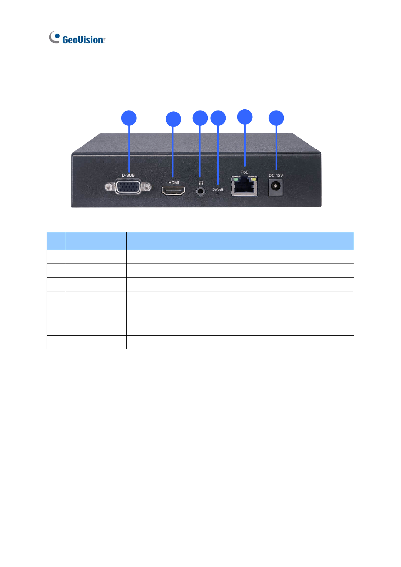
GV-IP Decoder Box Optimal
1
2
3 4
5
6
No.
Name
Function
1
VGA
Connect to a VGA monitor.
2
HDMI
Connect to an HDMI-compliant display device.
3
Audio Out
Connect to a speaker.
4
Default
Reset the device to the default factory settings. Use a pin to press
the default button for about 10 seconds. The system will then reset
and reboot itself shortly. See 5.2 Restoring Default Settings.
5
Network / PoE
Connect to the network or a PoE adaptor.
6
DC 12V
Connect to power by using a power adapter.
Introduction
27
1
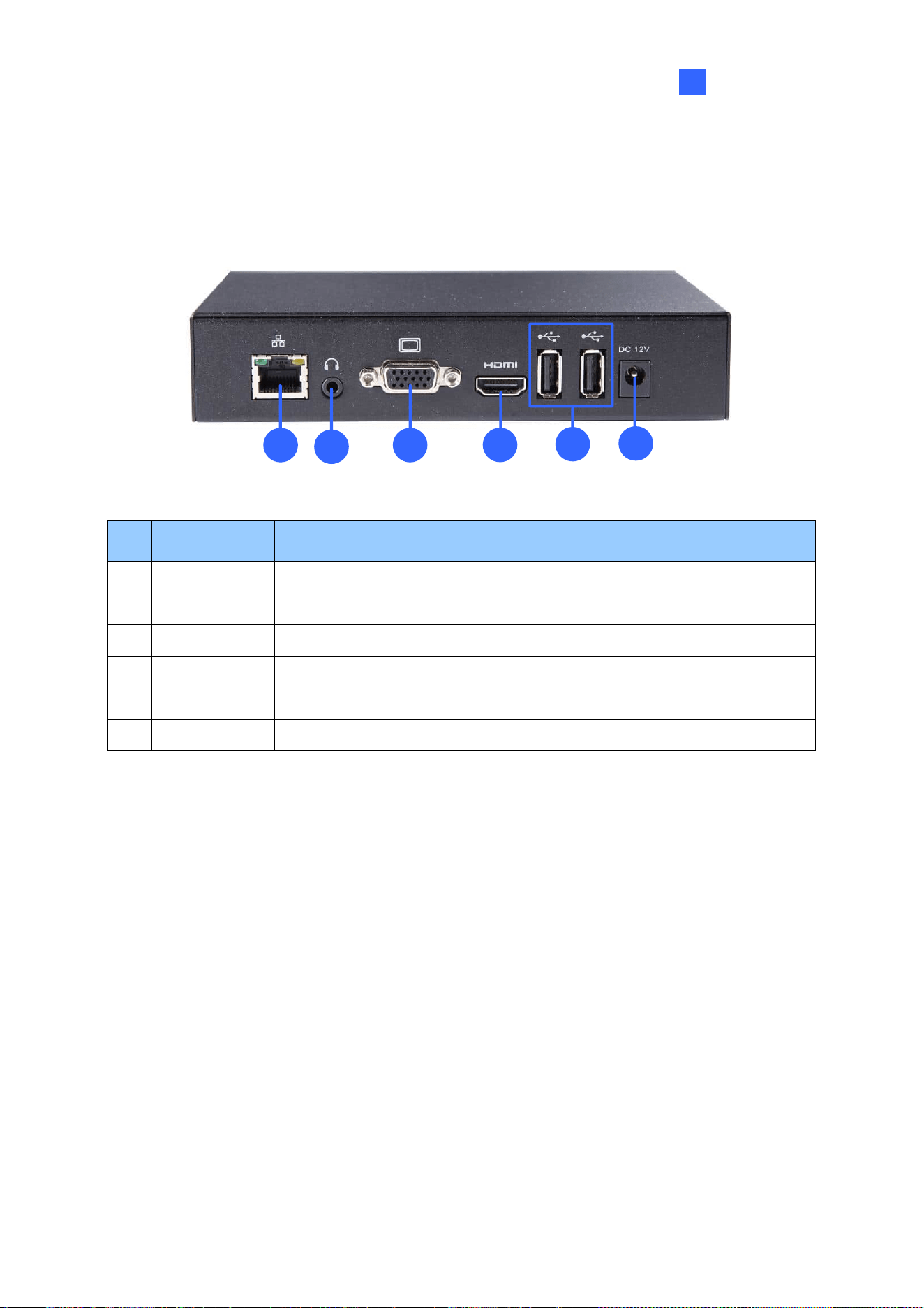
GV-IP Decoder Box Plus / Lite
1
5
3
4
6
2
No.
Name
Function
1
Network
Connect to the network.
2
Audio Out
Connect to a speaker.
3
VGA
Connect to a VGA monitor.
4
HDMI
Connect to an HDMI-compliant display device.
5
USB
Connect to a GV-Joystick V2, USB mouse, or USB storage device.
6
DC 12V
Connect to power by using the supplied power adapter.
28
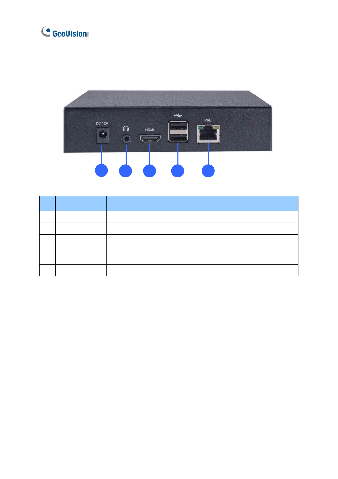
GV-IP Decoder Box Ultra
1
2 3 4
5
No.
Name
Function
1
DC 12V
Connect to power by using a power adapter.
2
Audio Out
Connect to a speaker.
3
HDMI
Connect to an HDMI-compliant display device.
4
USB 2.0
Connect to a GV-Joystick V2, USB mouse, or USB storage
device.
5
Network / PoE
Connect to the network or a PoE adaptor.
Introduction
29
1
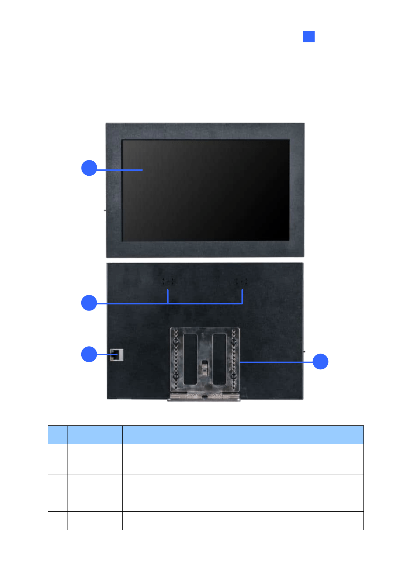
1.11.2 GV-Pad Mini / GV-IP Display 101 / GV-IP Display 116
1.11.2.1 Front and Rear Views
1
4
2
3
4
No.
Name
Function
1
LCD screen
Display the system settings of the device and the images of connected
IP devices.
2
Speaker
Listen to the audio around the connected IP device.
3
Ethernet Port
Connect to the network.
4
Stand
Position GV-Pad Mini / GV-IP Display 101 / 116 to your preference.
30
1.11.2.2 Top, Left-Side and Right-Side Views
1
2
3
4
5
7
8
6
No.
Name
Function
1
Micro SD Card
Slot
Connect to a micro SD card for local storage of content and firmware
upgrade.
2
LED Indicators
The red LED indicates the power is supplied.
The green LED indicates the system is ready.
3
Stand By
Press to enter Standby/Sleep mode. In standby mode, the screen
turns off to minimize power consumption. Press the key again to enter
ON mode.
4
Power Off/On
Switch the power on or off.
Introduction
31
1
No.
Name
Function
5
DC 12V
Connect to power using the supplied power adapter.
6
USB
Connect to a GV-Joystick V2, USB mouse, or USB storage device for
local storage of content and firmware upgrade.
7
Line Out Port
Connect to a headphone or speaker.
8
Default
Reset the device to the default settings. Use a pin to press the default
button for about 5 to 10 seconds. The system will then reset and
reboot itself shortly. See 5.2 Restoring Default Settings.
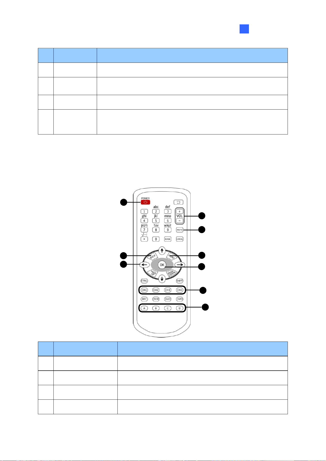
1.11.3 GV-IR Remote Control
GV-IR Remote Control is only supported by GV-IP Decoder Box Mini / Optimal / Ultra.
4
4
3
2
6
7
8
9
1
No.
Name
Function
1
Power
Turn on/off the screen.
2
Back
Return to the previous page in the Main Screen.
3
Menu Control
Move up, down, right and left in the Main Screen.
4
Volume Control
Increase or decrease the volume.
32
5
Mute
Mute the volume.
6
Menu
Switch to the Main Screen.
7
OK
Enter the setup options or save the settings in the Main Screen.
8
Hotkeys
Use the following hotkeys to execute commands when a
camera live view is selected in the main screen.
CH1: Take a screenshot
CH2: Activate the PTZ function.
CH3: Enter in full screen mode.
CH4: Activate the audio out function.
PTZ Controls
No.
Name
Function
2
Menu Control
Control PTZ movements (pan and tilt) on live view display when
the PTZ function is enabled.
6
OK
Bring the camera to a home position when the PTZ function is
enabled.
Press an alphabet key to adjust the zoom / focus.
No.
Alphabet Key
Function
8
A
Zoom In
B
Zoom Out
C
Focus In
D
Focus Out
Getting Started
33
2
Chapter 2 Getting Started
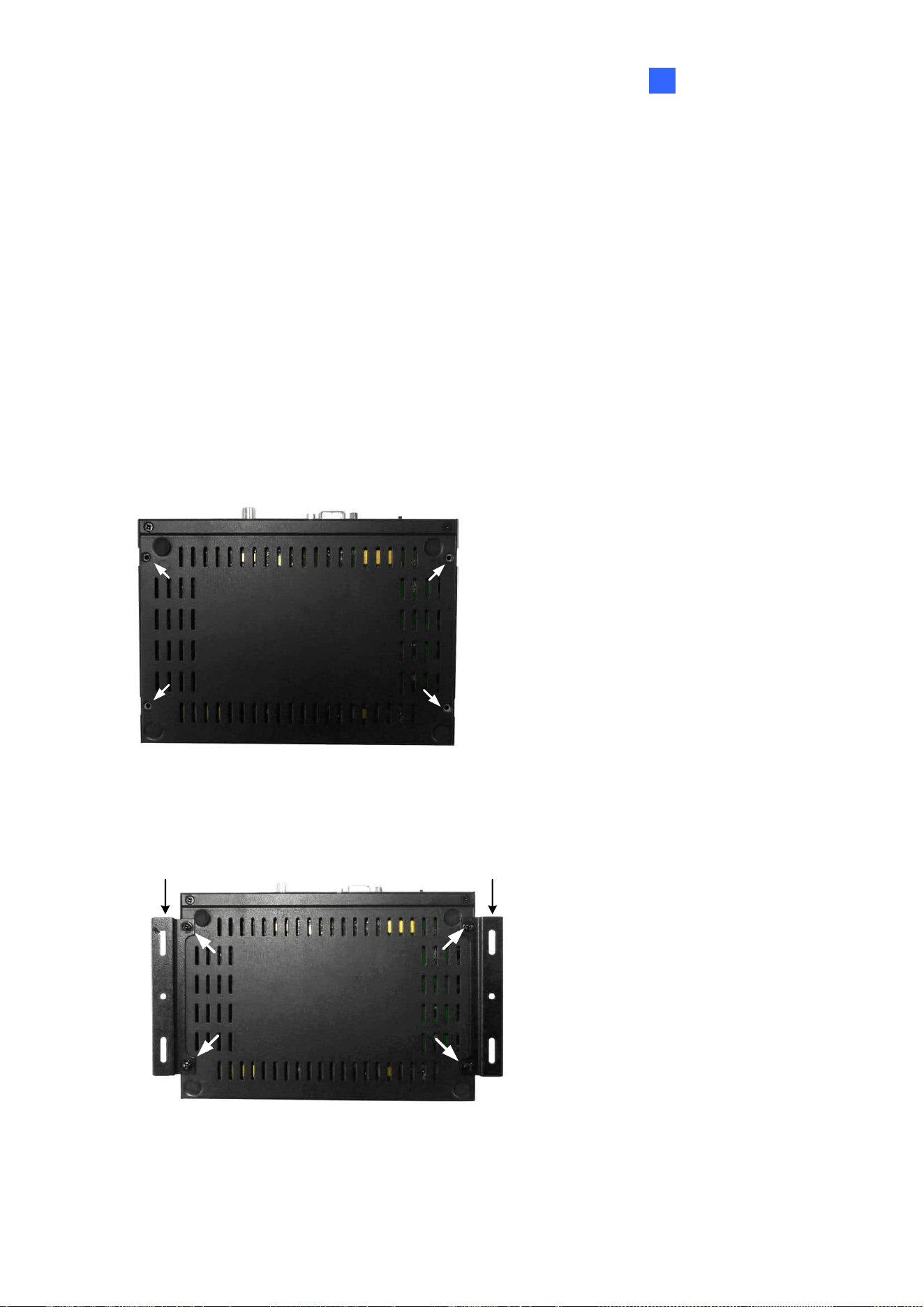
2.1 Installing GV-IP Decoder Box
You can install GV-IP Decoder Box on the wall or simply use it as desk mount device.
Wall Mount Installation
For wall mount installation, you need to purchase the wall mount kit.
1. Unscrew the 4 screws on the back panel of GV-IP Decoder Box.
2. Use the 4 small screws in the package to tighten the L-type brackets on GV-IP Decoder
Box.
L-type bracket L-type bracket
3. Secure GV-IP Decoder Box to the wall with self-prepared screws.
34
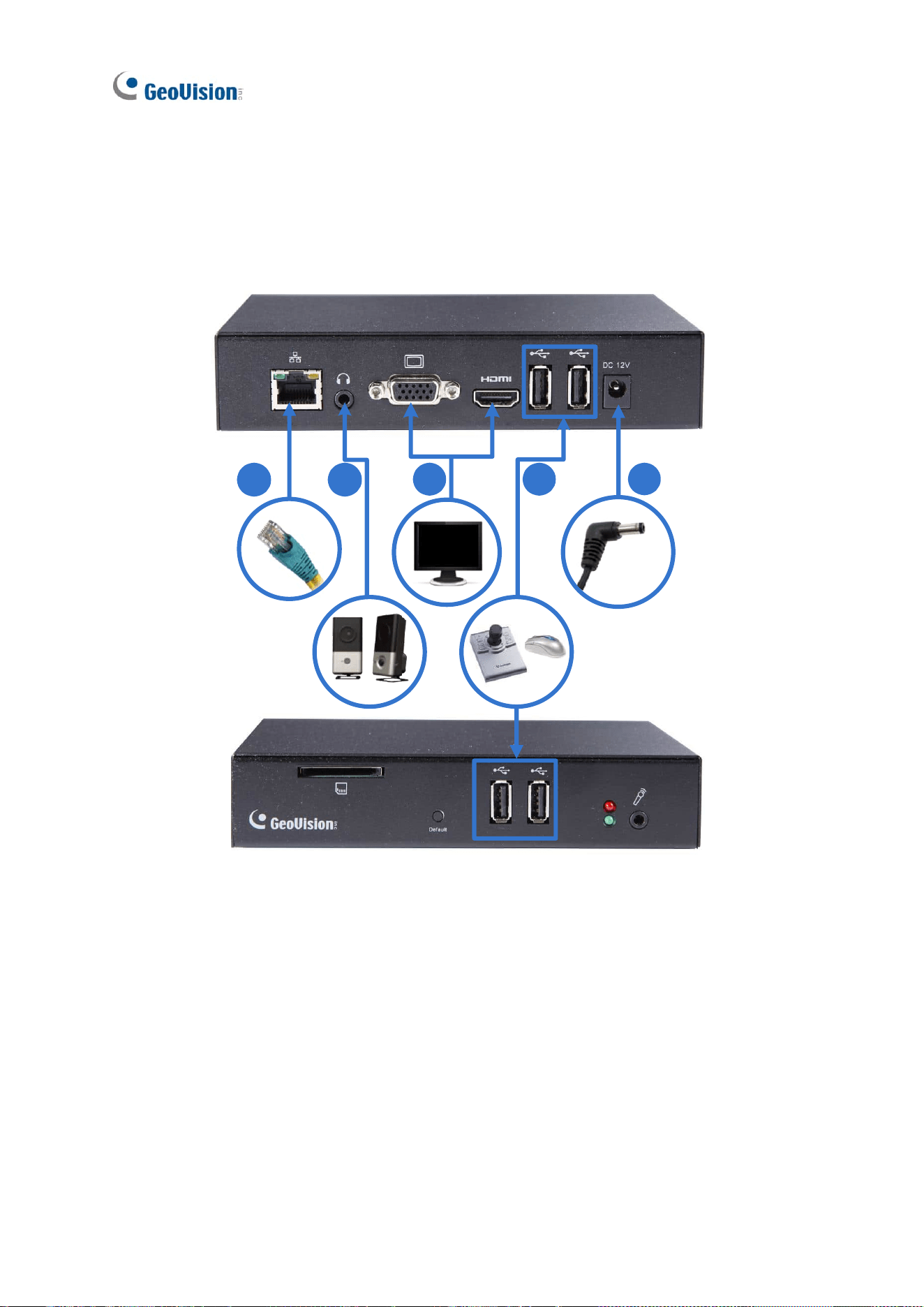
2.2 Connecting GV-IP Decoder Box Series
Follow the steps below to connect GV-IP Decoder Box series. Here we use GV-IP Decoder
Box Plus as an example.
4
1 2
5
3
1. Connect the device to the LAN port using an RJ-45 cable.
2. Connect a speaker to the audio line out port if needed.
3. Connect a display device to VGA or HDMI connector for video output.
4. Connect a mouse and / or GV-Joystick V2 to the USB ports.
5. Connect to power using the supplied power adapter.

Getting Started
35
2
Note:
1. You can only connect GV-IP Decoder Box Ultra / Plus / Lite to one display device through
either the HDMI or VGA connector at a time. Dual monitor display is only available for
GV-IP Decoder Box Optimal.
2. The default video output resolution is set to 1080P for GV-IP Decoder Box Optimal and
HD 720P for GV-IP Decoder Box Ultra / Plus / Lite. If you use a VGA monitor, be sure to
change the output resolution to VGA 1920 x 1080. To change the output resolution, see
4.1 System.
3. To configure GV-IP Decoder Box Optimal / Ultra for 4K resolution, make sure your
monitor is 4K-capable and set the resolution to 3840 x 2160. To change the output
resolution, see 4.1 System.
36
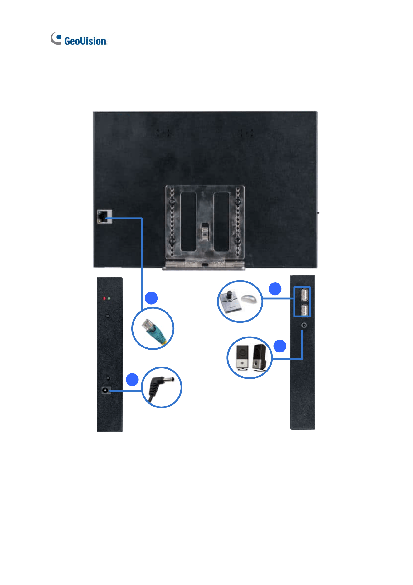
2.3 Connecting GV-Pad Mini / GV-IP Display 101 / 116
Follow the steps below to connect GV-Pad Mini / GV-IP Display 101 / 116.
1
2
4
3
1. Connect the device to the LAN port using an Ethernet cable.
2. Connect to power using the supplied power adapter.
3. Connect a speaker / headphone to the line out port if needed.
4. Connect a mouse and / or GV-Joystick V2 to the USB ports.
Getting Started
37
2
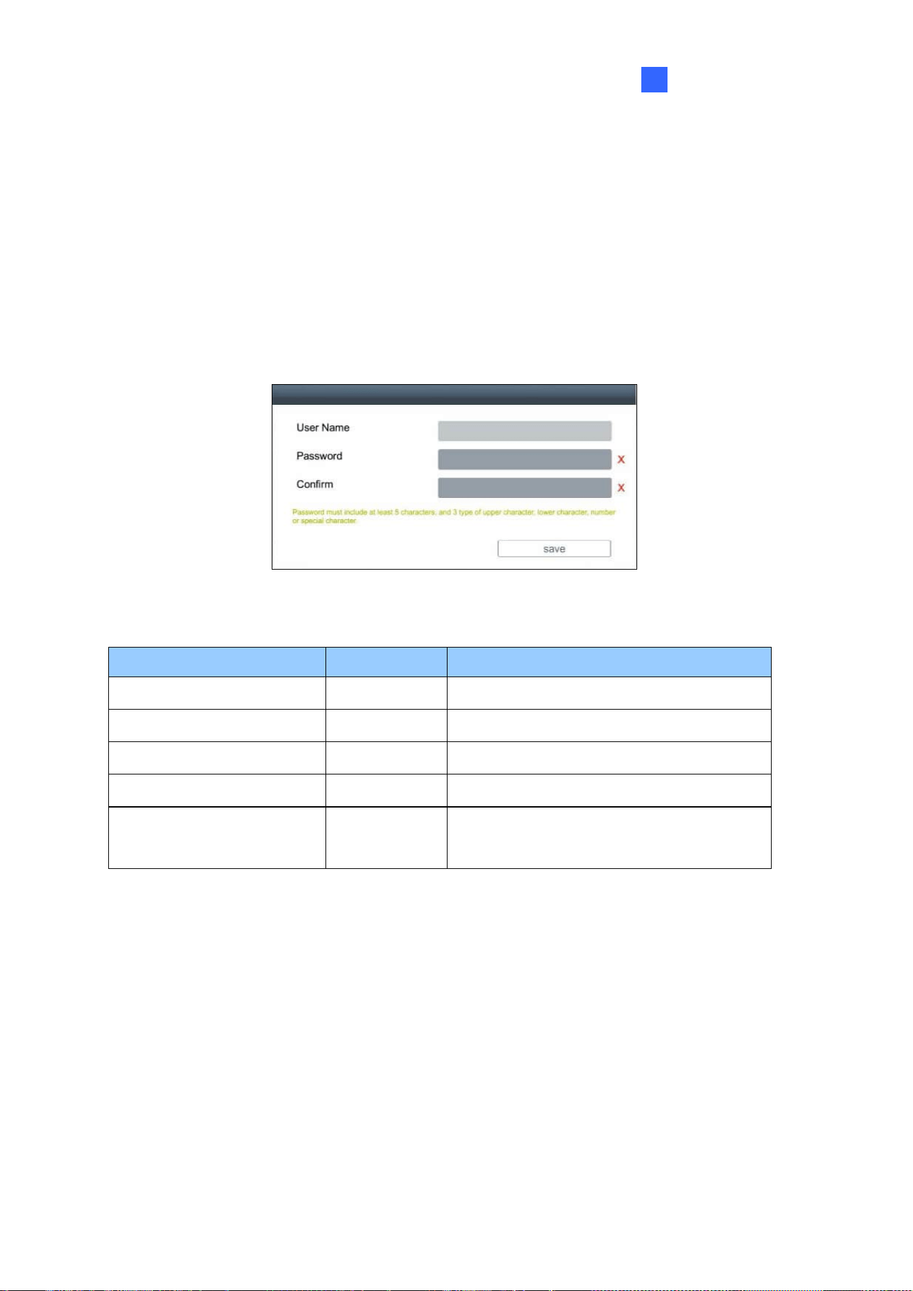
2.4 The Main Screen
After you have connected the necessary wires and cables, GV-IP Decoder Box series /
GV-Pad Mini / GV-IP Display series will turn on and show the main screen on the monitor.
First-time users must create login credentials when the following interface appears.
Alternatively, you can use the GV-IP Device Utility to create the login credentials. For details,
see Creating GV-IP Device’s Login Credentials at the beginning of the manual.
GV-IP Device Login Credential Requirements
Device Model
Firmware
Login Credential Setup
GV-IP Decoder Box Mini
-
Must create login credentials on first use
GV-IP Decoder Box Optimal
V1.06 or later
Must create login credentials on first use
GV-IP Decoder Box Ultra
V1.09 or later
Must create login credentials on first use
GV-IP Display 116
-
Must create login credentials on first use
All other Decoder Box /
Display models
-
Default login: admin / admin
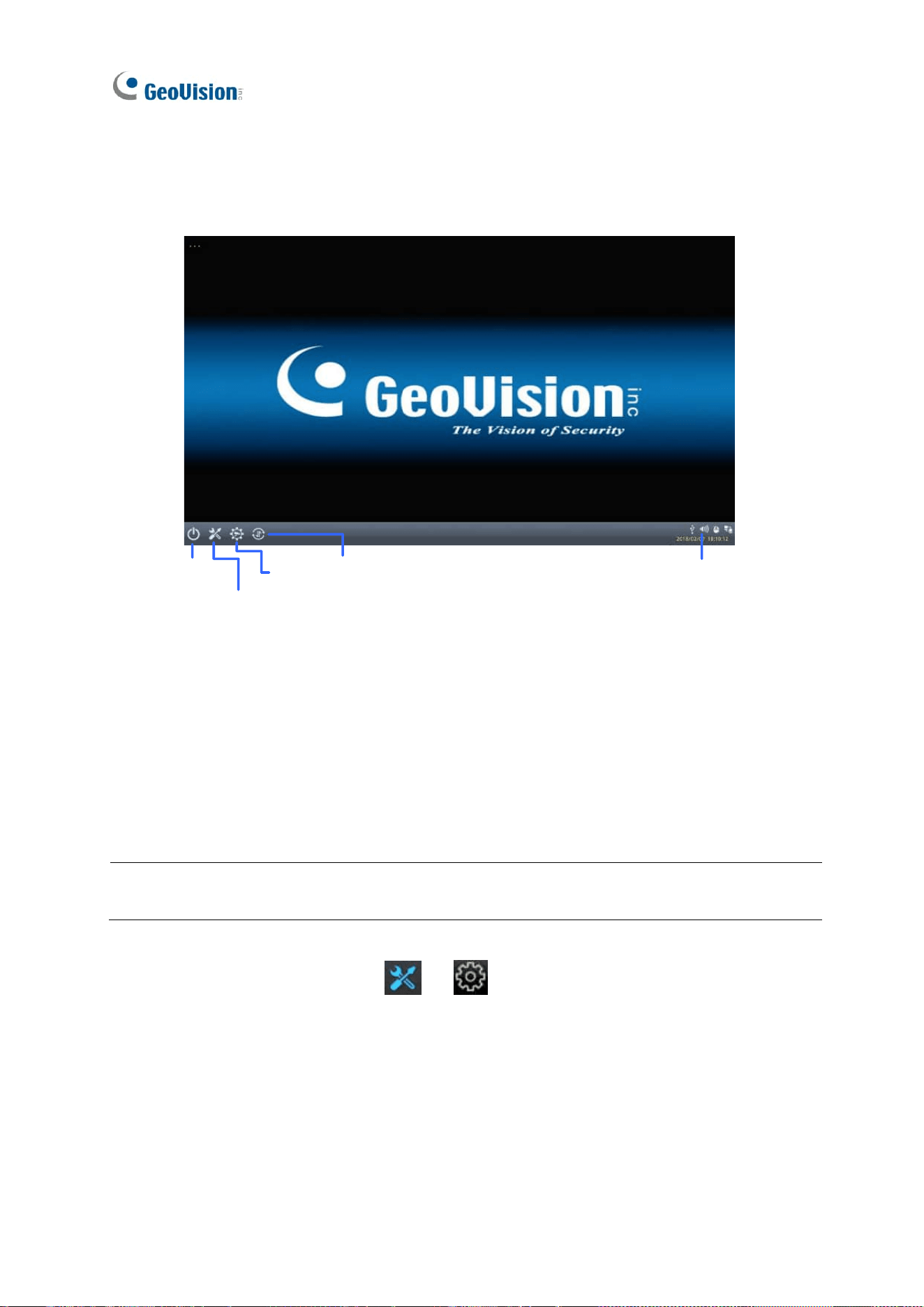
38
The user interfaces and settings differ by model. Here we use GV-IP Decoder Box Ultra /
GV-IP Display 101 as an example.
Reboot
System
Setting
Camera
Search
Update
Adjust
Volume
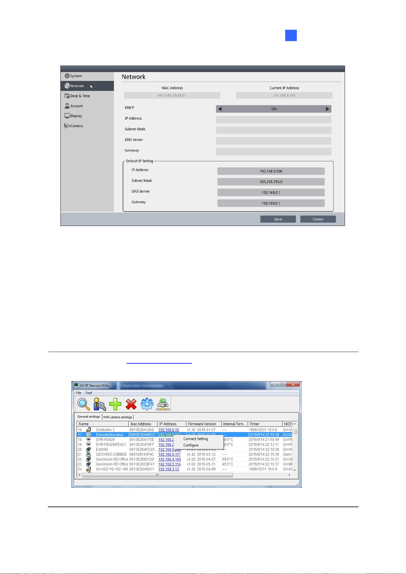
2.5 Setting Up the Network
By default, GV-IP Decoder Box series / GV-Pad Mini / GV-IP Display series will be
automatically assigned an IP address by the DHCP server without requiring additional
settings. To change the IP address to a fixed one, follow the steps below.
Note: By default, if a Decoder Box or Display model is connected to LAN without the DHCP
server, it will be assigned a static IP address: 192.168.0.100.
1. Click the System Settings icon or at the bottom of the main screen, and
select Network. You will see the following window.
Getting Started
39
2
2. To configure the static IP address,
• For GV-IP Decoder Box Mini / Optimal / Ultra / GV-IP Display 101 / 116, switch the
DHCP option to OFF.
• For GV-IP Decoder Box Plus / Lite / GV-Pad Mini, select Static IP Address.
3. Fill out the fields of IP Address, Subnet Mask, DNS Server, and Default Gateway.
4. Click Save. When the device is connected to the network, the IP address will be shown in
the Connected IP Address field.
Tip: You can also use GV-IP Device Utility to modify the IP address by clicking on a
Decoder Box or Display in the list and selecting Configure.
40
2.6 Adding IP Devices to Live View Grid
Before you start, make sure all the IP devices or GV-Mobile Server is on the same LAN as
GV-IP Decoder Box series / GV-Pad Mini / GV-IP Display series.
Cameras from GV-IP devices, GV-Mobile Servers, or third-party IP devices can be added to
the Decoder Box or Display via the Camera Search function, manually, or through the GV-IP
Device Utility. Refer to:
2.6.1 Adding IP Devices through Automatic Search
2.6.2 Adding IP Devices Manually
2.7 Adding IP Devices Using GV-IP Device Utility
Each live view grid supports up to 64 camera channels. By default, camera channels are
looped at 30-second intervals within each grid division on the Decoder Box’s monitor or
Display’s monitor.
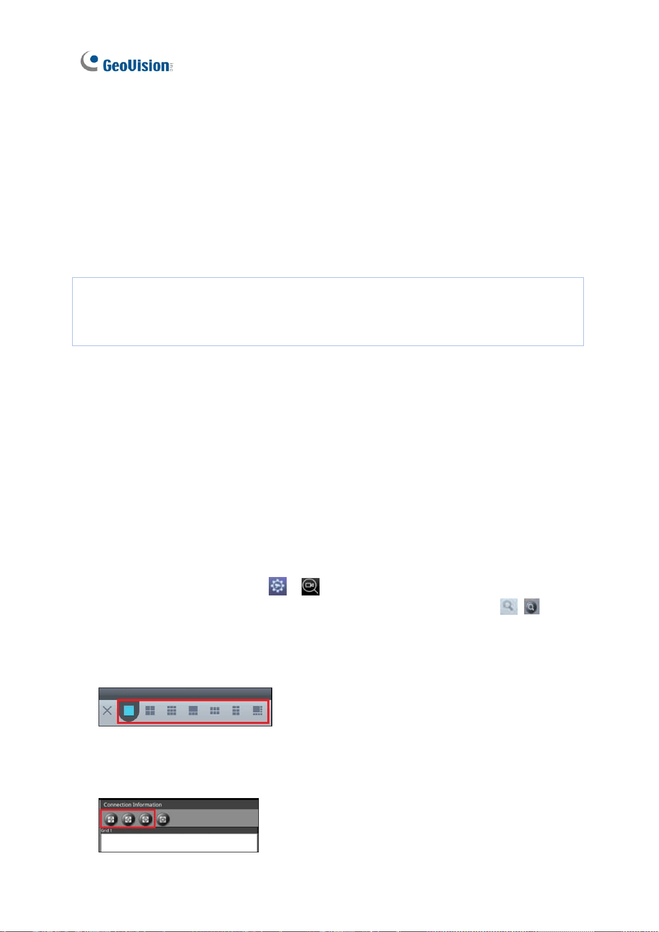
2.6.1 Adding IP Devices through Automatic Search
To add IP devices or GV-Mobile Server to the Decoder Box or Display to display their
cameras, follow the steps below:
1. Click the Camera Search icon / on the main page.
2. To search for IP devices on the same LAN, click the Search Camera icon / .
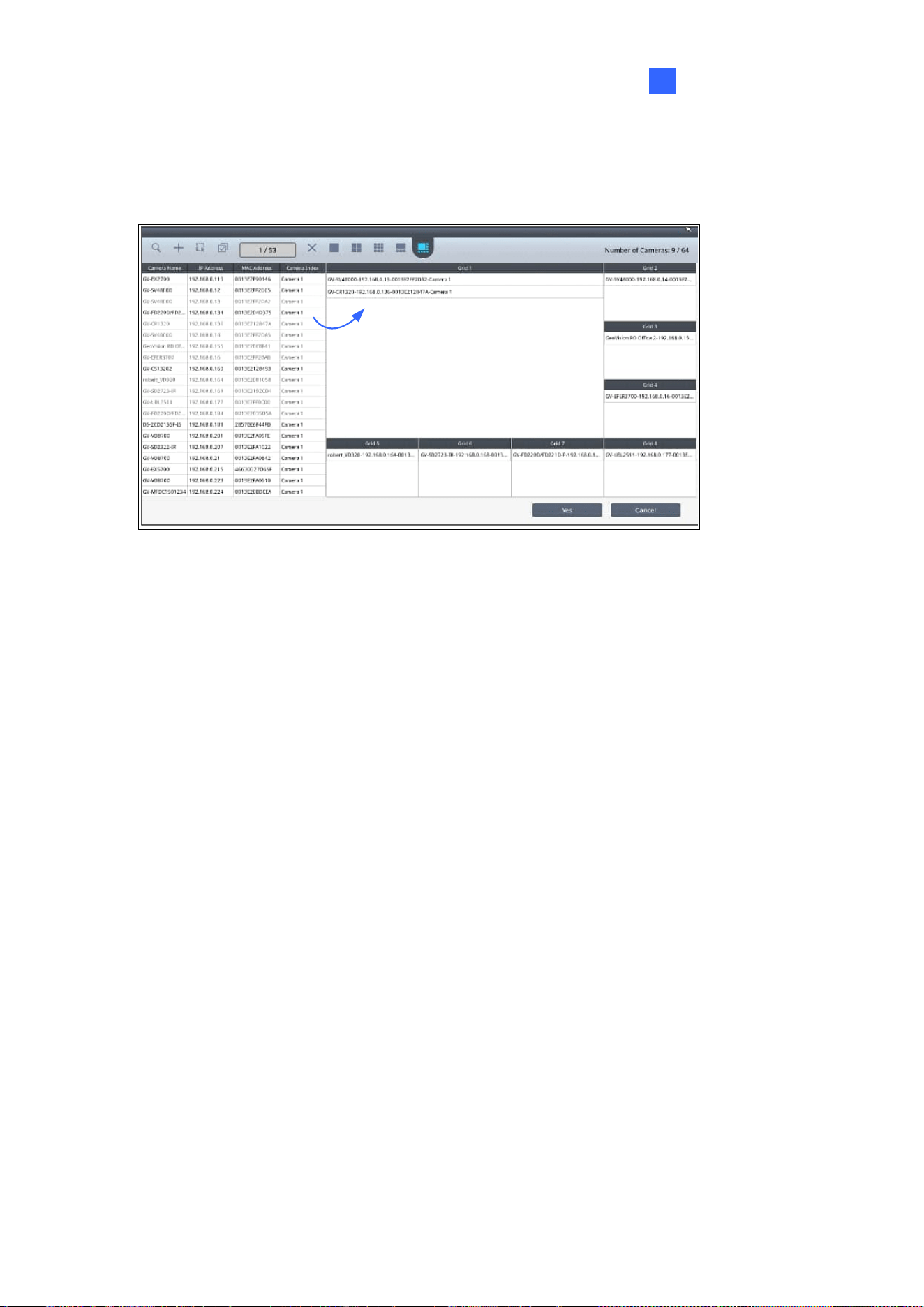
3. Select a live view grid.
For GV-IP Decoder Box Mini / Optimal / Ultra / GV-IP Display 101 / 116:
(This figure uses GV-IP Decoder Box Optimal as an example)
For GV-IP Decoder Box Plus / Lite / GV-Pad Mini:
Getting Started
41
2
4. Drag and drop IP devices from the camera list to the grid divisions. To select multiple
cameras at once, click Select Multiple Cameras at the top and select more than one
from the camera list.
5. To change the camera settings, hold for right-clicking on a camera in the grid and select
Edit to modify the following settings:
◼ Camera Name: Name the camera.
◼ Port: Change the port number if needed.
◼ Loop Time Interval: Specify a time interval, ranging from 10 ~ 600 seconds, for the
camera to display before switching to the next one. The default value is 30 seconds.
◼ Login Information: Change the login username and password of the camera.
◼ Stream Mode: Only for GV-IP Decoder Box Mini / Optimal / Ultra / GV-IP Display
116, select one of the following stream modes.
Single Stream: Select this option for the highest image quality.
Single Stream (Save bandwidth): Select this option for the lowest bandwidth.
Dual Stream: Select this option to automatically optimize the image quality
when displaying multiple channels.
42
6. To adjust the display order of cameras, hold for right-clicking on a camera and click Move
Up or Move Down.
7. To remove a camera, hold for right-clicking on a camera and click the Delete button.
8. To delete all the added devices at once, click the Delete All button / .
9. Click Yes or Save to apply the settings.
The selected cameras will be displayed on the Decoder Box’s monitor or Display’s monitor,
and be looped at a 30-second interval by default.
Note:
1. Refer to 3.1 Live View for the maximum resolution supported in different live view
layouts.
2. Fisheye dewarping is only supported by GV-IP Decoder Box Plus. To dewarp the fisheye
view, you need to choose 1-division layout or assign the camera to Grid 1 of Quad View.
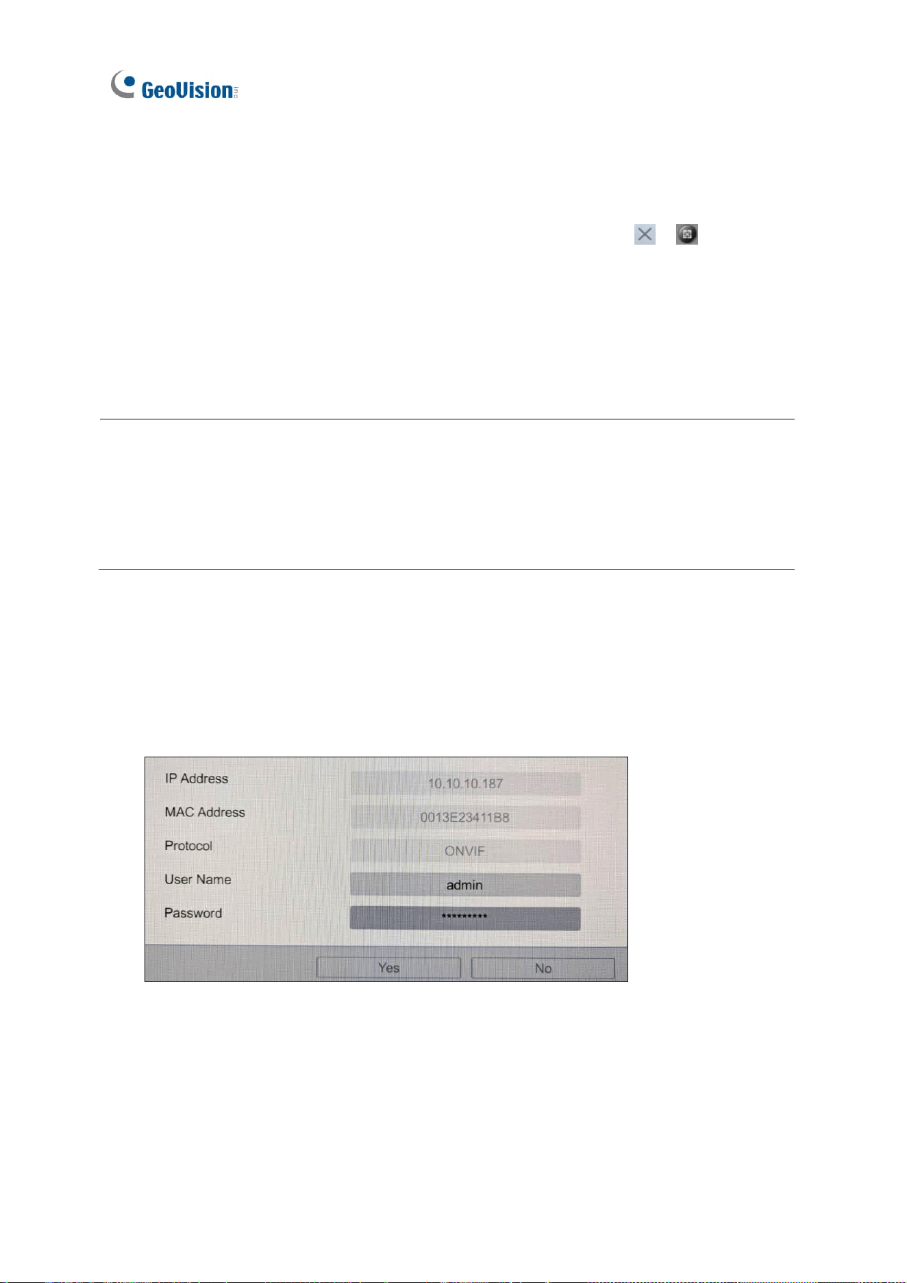
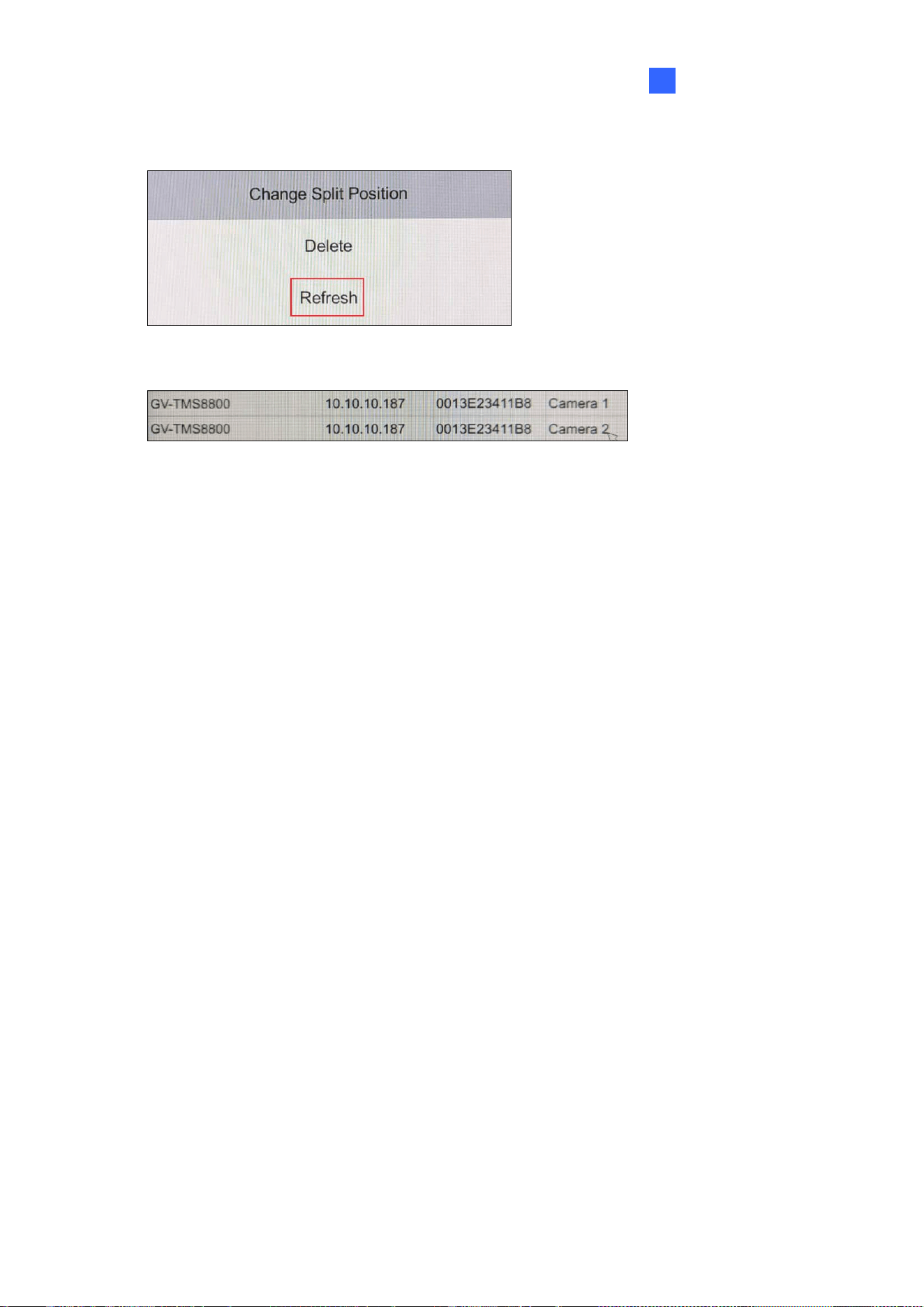
To display multiple channels from a multi-sensor camera or UA-XVR / XVL model:
1. Double-click the camera or device from the camera list.
2. On this dialog box, enter the camera or device’s login username and password, and
click OK.
Getting Started
43
2
3. Click Refresh.
The multiple channels of the camera or device are displayed on the camera list.
44
2.6.2 Adding IP Devices Manually
If the Decoder Box or Display is unable to detect an IP device using the Camera Search
function, you can manually search for it.
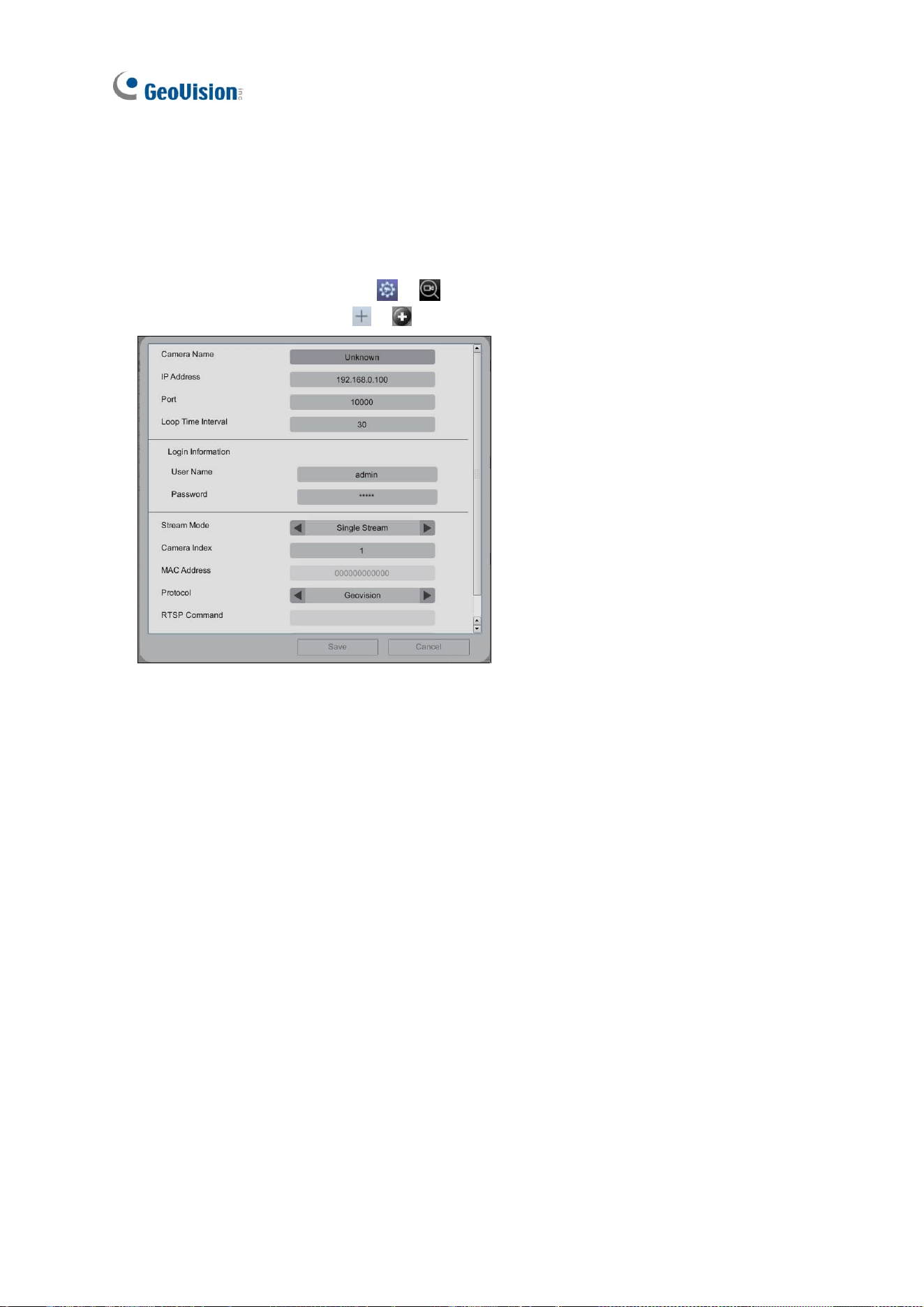
1. Click the Camera Search icon /
at the bottom of the main page.
2. Click the Add Camera icon / . This dialog box appears.
3. Enter the following IP device information.
◼ Camera Name: Name the IP device.
◼ IP Address: Type the IP address of the IP device.
◼ Port: Change the port number if needed. The default port is 10000.
◼ Loop Time Interval: Specify a time interval, ranging from 10 ~ 600 seconds, for the
the camera of the IP device to display before switching to the next one. The default
value is 30 seconds.
◼ Login Information: Type the ID and password of the IP device.
◼ Stream Mode: Only for GV-IP Decoder Box Mini / Optimal / Ultra / GV-IP Display
116, select one of the following modes.
Single Stream: Select this option for the highest image quality.
Single Stream (Save bandwidth): Select this option for the lowest bandwidth.
Dual Stream: Select this option to automatically optimize the image quality
when displaying multiple channels.
◼ Camera Index: Number the IP device for searching convenience.

Getting Started
45
2
◼ Protocol: For GV-IP devices, select Geovision as the protocol. For third-party
devices, select ONVIF or one of the RTSP protocols.
◼ RTSP Command: Type the RTSP link if you want to connect the IP device through
RTSP protocols.
4. Click Save. The IP device is now added to the camera list.
5. To add the camera of the IP device to the live view grid, see Steps 4 ~9, 2.6.1 Adding IP
Devices through Automatic Search.
46
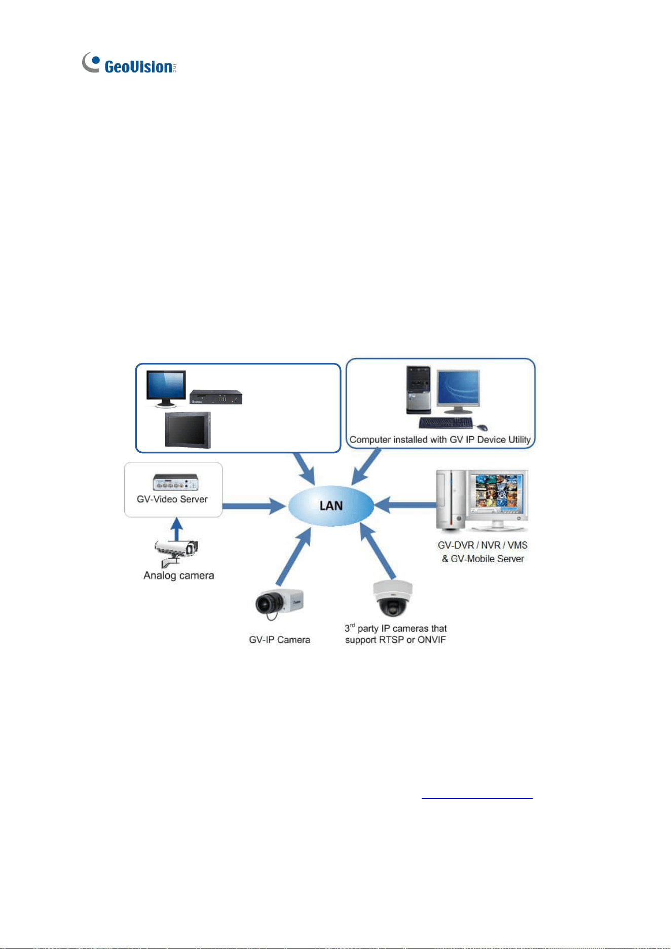
2.7 Adding IP Devices Using GV-IP Device Utility
You can use GV-IP Device Utility to add cameras from GV-IP devices, GV-Mobile Server, or
ONVIF devices.
Each live view grid supports up to 64 camera channels. By default, camera channels are
looped at 30-second intervals within each grid division on the Decoder Box’s monitor or
Display’s monitor.
Before you start, make sure that all the IP devices and software are on the same LAN as
GV-IP Decoder Box series / GV-Pad Mini / GV-IP Display series.
GV-IP Decoder Box Optimal /
GV-Pad Mini /
GV-IP Display 101 / 116
Ultra / Plus
2.7.1 Adding GV-IP Devices
To display cameras from GV-IP devices or GV-Mobile Server, use the GV-IP Device Utility to
add them to the Decoder Box or Display.
1. Run GV-IP Device Utility, which can be downloaded from GeoVision’s website. Once
started, the utility will automatically search for IP devices on the same LAN.
2. Click on the IP address of a Decoder Box or Display, and select Connect Setting. A login
window appears.
Getting Started
47
2
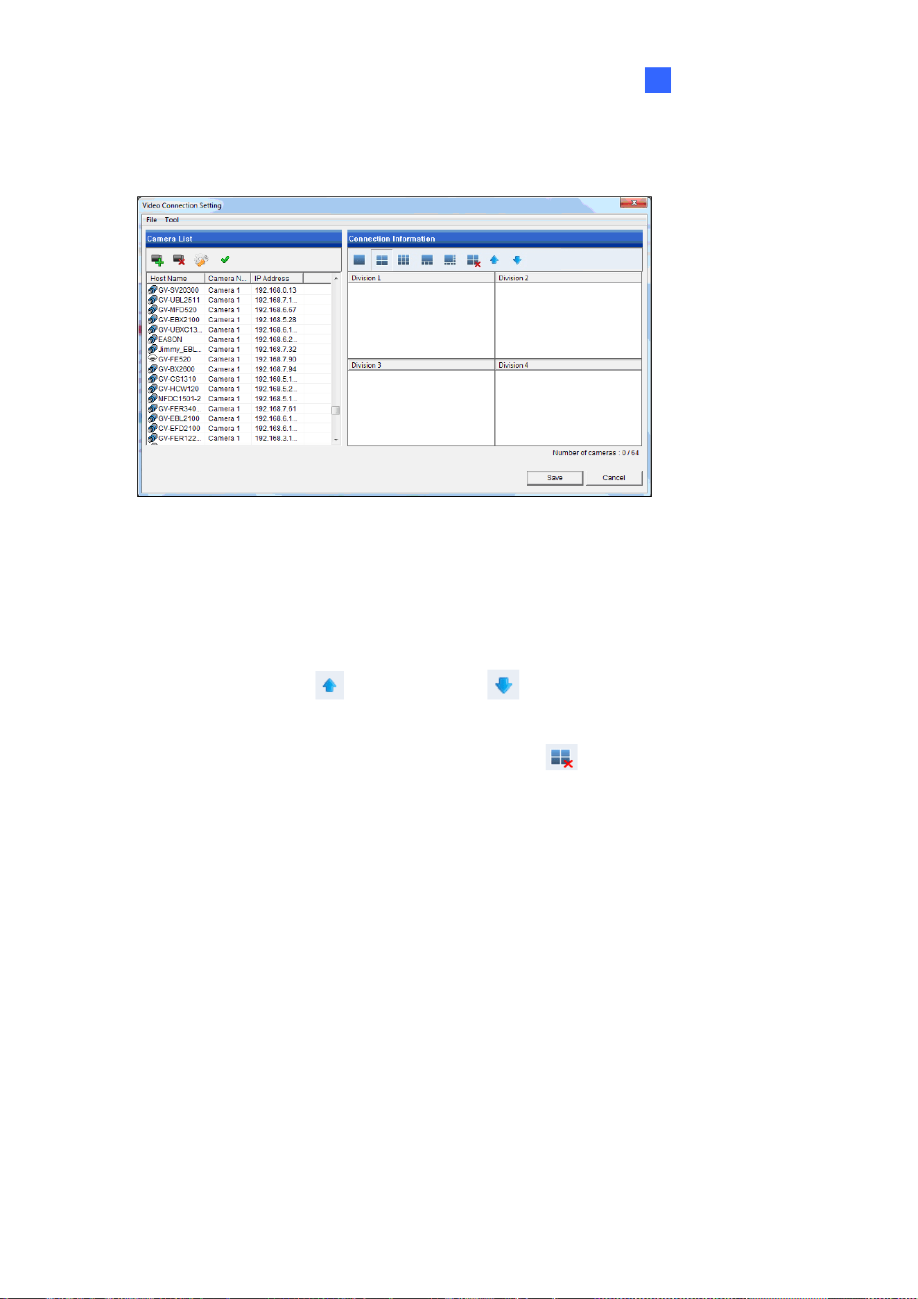
3. Type the username and password of the Decoder Box or Display, and click OK. This
window appears.
4. Use the Camera List toolbar to add, remove, or configure a camera in the Camera List.
5. Under Connection Information, select a live view grid.
6. Add camera channels to the grid divisions.
A. Drag and drop up to 48 cameras from the Camera List to a grid division.
B. Use the Move Up and Move Down buttons to change the display order
of cameras.
C. To remove a selected camera, click the Remove button.
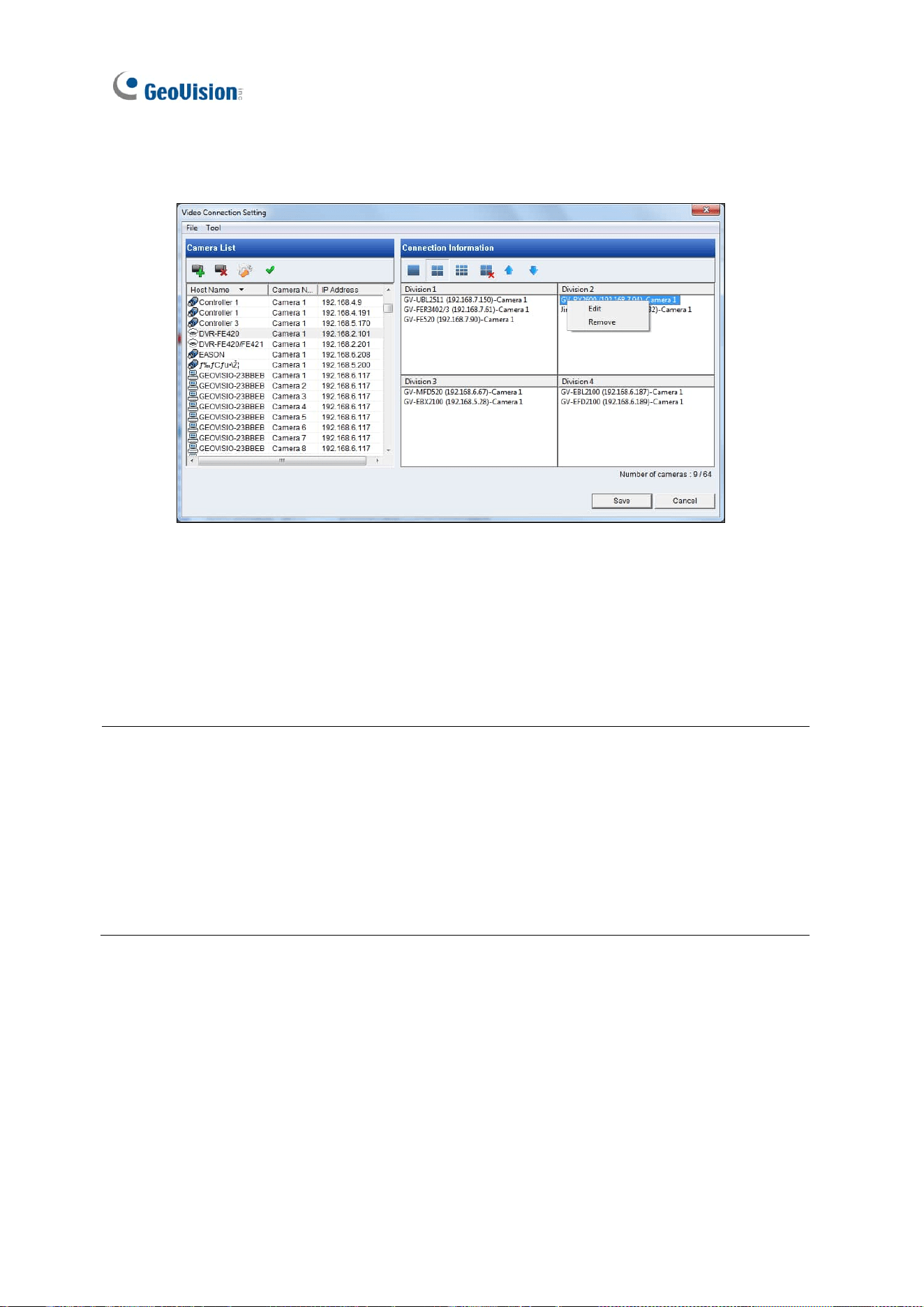
48
D. To enter the login username and password of the camera, right-click it and select
Edit.
7. Click Save.
The selected cameras will be displayed on the Decoder Box’s monitor or Display’s monitor,
and be looped at a 30-second interval by default.
Note:
1. Only for GV-Decoder Box Mini / Optimal / Ultra, you can also configure the stream
mode and loop time interval for a specific or all IP devices connected on the Edit page
(Step 6-D).
2. Fisheye dewarping is only supported by GV-IP Decoder Box Plus. To dewarp the
fisheye view, you need to choose 1-division layout or assign the camera to Grid 1 of
Quad View.
Getting Started
49
2
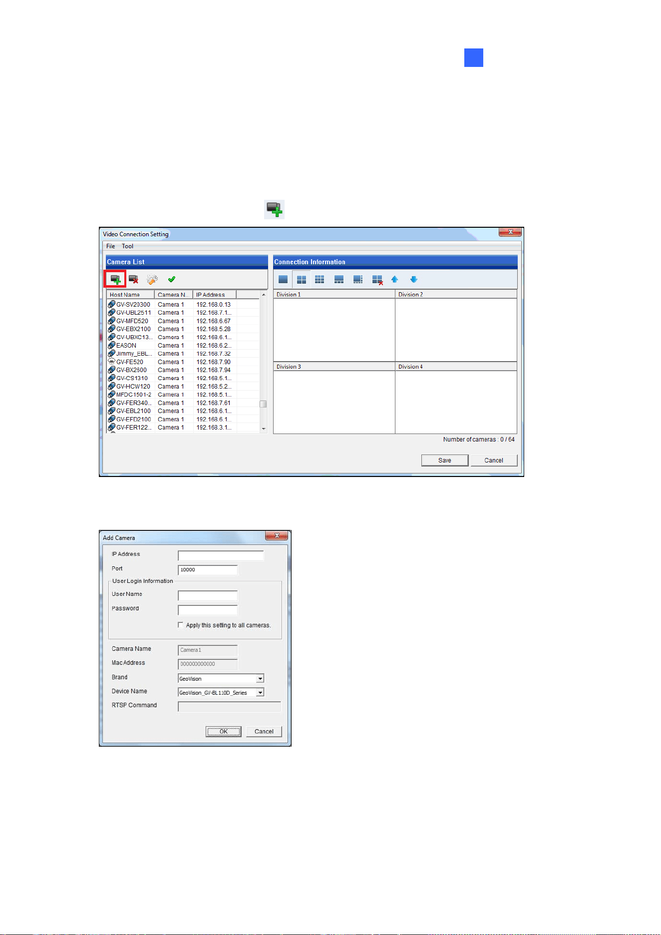
2.7.2 Adding Third-party Devices
To display cameras from third-party RTSP or ONVIF IP devices, use the GV-IP Device Utility
to add them to the Decoder Box or Display.
1. Click the Add Camera button on the Video Connection Setting window.
2. Type the IP address, username, and password of the third-party IP device.
50
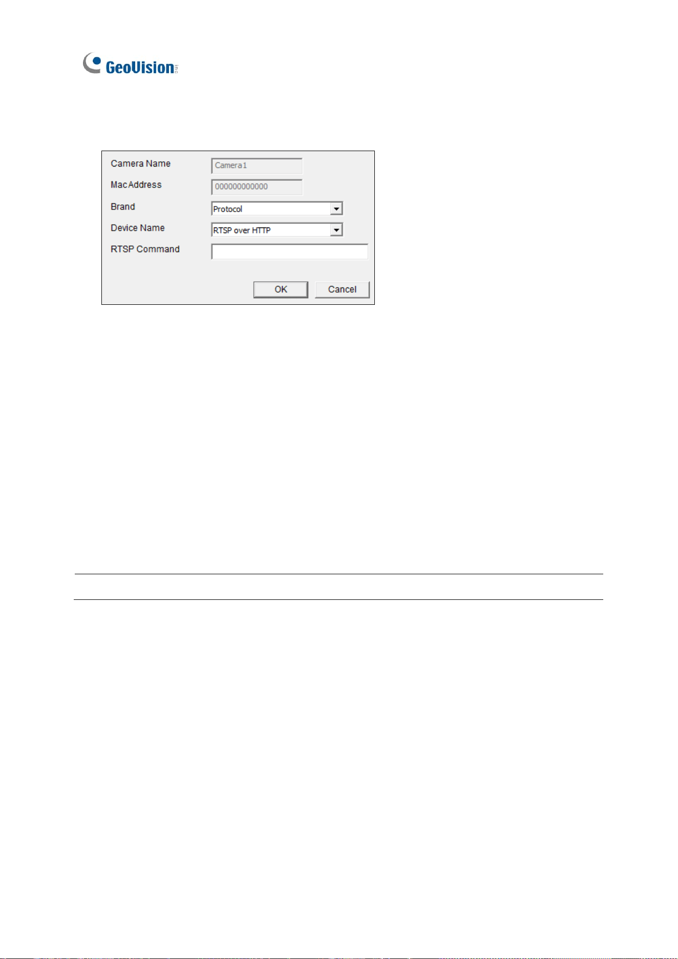
3. Select Protocol for Brand, and one of the following protocols for Device Name. Type the
RTSP command if required. Refer to the third-party IP device’s manual for this command.
◼ ONVIF: Select this protocol if the IP device adheres to ONVIF.
◼ RTSP over HTTP: The RTSP protocol uses an HTTP port for data streaming from
the IP device.
◼ RTSP over TCP: The RTSP protocol uses a TCP port for data streaming from the
IP device.
◼ RTSP over UDP: The RTSP protocol uses a UDP port for data streaming from the
IP device.
4. Click OK. The third-party IP device is added to the camera list.
5. To add the camera of the third-party IP device to the live view grid, see Step 6, 2.7.1
Adding GV-IP Devices.
Note: GV-IP Decoder Box Light does not support RTSP connection.
Accessing Live View
51
3
Chapter 3 Accessing Live View
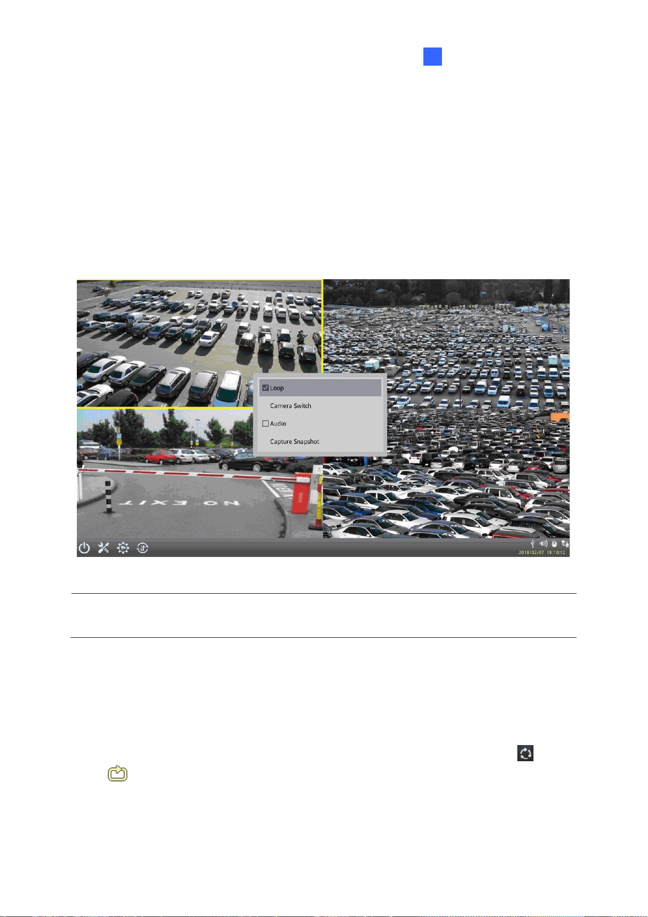
3.1 Live View
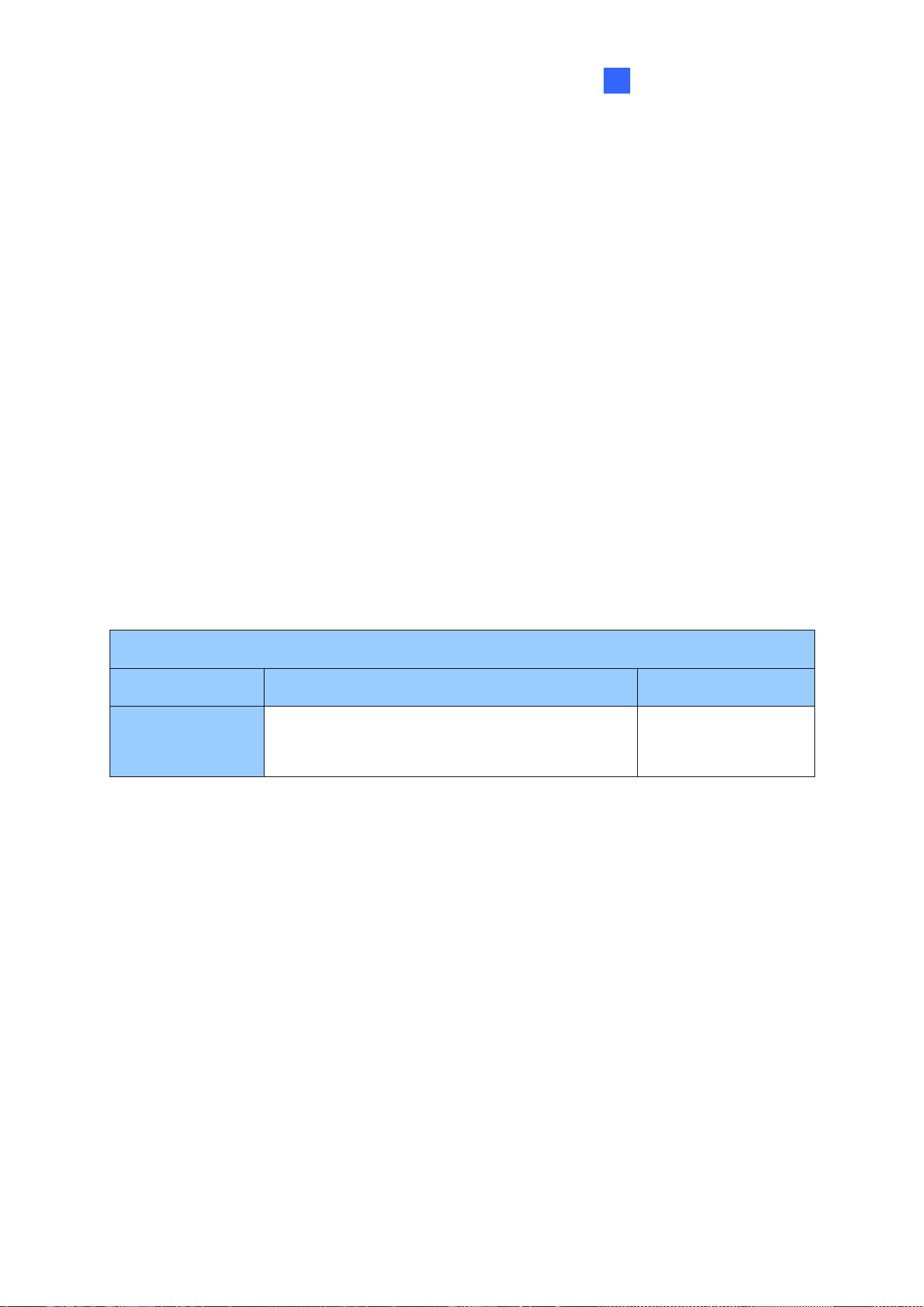
After adding IP devices to the live view grid, their camera feeds are displayed on the Decoder
Box or Display main screen. Hold for right-clicking on a grid division to access the following
options:
Note: The main screen may vary slightly by model. Here we use GV-IP Decoder Box Ultra /
GV-IP Display 101 as an example.
◼ Capture Snapshot: Only supported by GV-IP Decoder Box Mini / Optimal / Ultra / Plus /
GV-Pad Mini / GV-IP Display 101 / 116, capture a snapshot of the live view. This option
is only available when the live view grid is not looping. See 3.2 Capturing Snapshots.
◼ Play Mode: When more than one device is added to a grid, select Loop to start looping
through devices or select a device to fix the live view grid to it. A looping icon or
will appear on the live view grid if you select Loop.
Note: To fix the live view grid to a selected device for GV-IP Decoder Box Mini / Optimal
/ Ultra, click Camera Switch and select the desired camera.
52
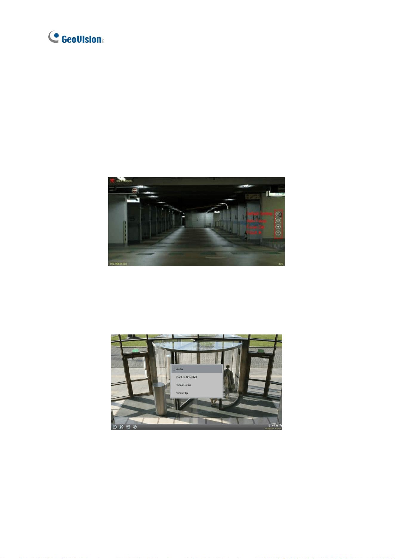
◼ PTZ: Select to allow GV-Joystick V2 / your mouse / GV-IR Remote Control to control the
PTZ device. To pan and tilt the live view, click and hold the arrow on the image. This
function is only available for devices with PTZ functions and only one PTZ device can
be enabled at a time.
◼ Audio: Enables the audio out function. You can only enable the audio out function of
one device at a time.
◼ Visual PTZ Button: Only for GV-IP Decoder Box Mini / Optimal / Ultra / Plus / GV-Pad
Mini / GV-IP Display 101 / 116, activate the PTZ control buttons. This function is only
available for devices with PTZ function.
Default Setting: Select to return to the camera’s home position.
Auto Focus: Automatically adjust the sharpness of the camera view.
Focus In / Out: Adjust the sharpness of the camera view.
◼ Video Rotate: Adjust the image orientation by selecting 0°, 90°, 180°, or 270°. The
Video Rotate is only available for the GV-IP Decoder Box Mini / Optimal / GV-IP Display
116 in 1080P or 4K (with Single View).
Accessing Live View
53
3
◼ Video Flip: Adjust the image orientation by selecting Normal, Horizontal, Vertical, or
Both. (not available for GV-IP Decoder Box Mini / Optimal / GV-IP Display 116)
Note the following live view specifications:
⚫ The resolution of the added device must be lower than the maximum resolution listed
below for each screen division. When the device resolution exceeds the maximum
resolution supported, GV-IP Decoder Box series / GV-Pad Mini / GV-IP Display series
will connect to stream 2 of the device instead. If stream 2 is unavailable, the message
“Resolution Error” will appear on the screen.
⚫ For a smooth operation for the GV-IP Decoder Box series, the bitrate of each channel
should be below 6 Mbps (for 16-CH division, the bitrate should be below 3 Mbps).
⚫ Fisheye dewarping is only supported by GV-IP Decoder Box Plus in Single View and
Grid 1 of Quad View.
⚫ 16-ch division display and 60 fps resolution are only supported by GV-IP Decoder Box
Optimal firmware V1.04 or later.
GV-IP Decoder Box Mini
Screen Division
Maximum Resolution
Fisheye Dewarping
1-Division
(Single View)
30 fps: 3840 x 2160
60 fps: 1280 x 720, 1920 x 1080
Not supported
54
GV-IP Decoder Box Optimal
Screen Division
Maximum Resolution
Fisheye Dewarping
1-Division
(Single View)
3840 x 2160: up to 30 fps, 30 fps in total
(1 CH max.)
1920 x 1080: up to 60 fps
Not supported
4-Division
(Quad View)
Grid 1: 2560 x 1920, Other 3 grids: 1920 x 1080
Up to 30 fps, 120 fps in total (4 CH max.)
Grid 1: 1920 x 1080: up to 60 fps
Other 3 grids: 1920 x 1080, up to 30 fps
6-Division
1280 x 720: up to 30 fps, 180 fps in total
(6 CH max.)
8-Division
1280 x 720: up to 30 fps, 240 fps in total
(8 CH max.)
9-Division
1280 x 720: up to 30 fps, 270 fps in total
(9 CH max.)
16-Division
640 x 480: up to 30 fps, 480 fps in total
(16 CH max.)
GV-IP Decoder Box Ultra
Screen Division
Maximum Resolution
Fisheye Dewarping
1-Division (Single View)
3840 x 2160: up to 30 fps, 30 fps in
total (1 CH max.)
Not supported
4-Division
(Quad View)
Grid 1
2560 x 1920
Up to 30 fps, 120
fps in total (4 CH
max.)
Other 3 Grids
1920 x 1080
6-Division
1280 x 720: up to 30 fps, 180 fps in
total (6 CH max.)
8-Division
1280 x 720: up to 30 fps, 240 fps in
total (8 CH max.)
9-Division
1280 x 720: up to 30 fps, 270 fps in
total (9 CH max.)
Accessing Live View
55
3
GV-IP Decoder Box Plus
Screen Division
Maximum Resolution
Fisheye Dewarping
1-Division (Single View)
2048 x 1944
Supported
4-Division
(Quad View)
Grid 1
2048 x 1944
Supported
Other 3 Grids
1920 x 1080
Not supported
9-Division
1280 x 720
Not supported
GV-IP Decoder Box Lite
Screen Division
Maximum Resolution
Fisheye Dewarping
1-Division (Single View)
1920 x 1080
Not supported
4-Division (Quad View)
GV-Pad Mini
Screen Division
Maximum Resolution
Fisheye Dewarping
1-Division (Single View)
2048 x 1944
Not supported
4-Division
(Quad View)
Grid 1
2048 x 1944
Other 3 Grids
1920 x 1080
9-Division
1280 x 720
GV-IP Display 101
Screen Division
Maximum Resolution
Fisheye Dewarping
1-Division (Single View)
3840 x 2160
Not supported
4-Division
(Quad View)
Grid 1
2560 x 1920
Other 3 Grids
1920 x 1080
6-Division
1280 x 720
8-Division
1280 x 720
9-Division
1280 x 720
56
GV-IP Display 116
Screen Division
Maximum Resolution
Fisheye Dewarping
1-Division (Single View)
3840 x 2160: up to 30 fps,
30 fps in total (1 CH max.)
Not supported
4-Division
(Quad View)
Grid 1
2560 x 1920
Up to 30 fps, 120
fps in total (4 CH
max.)
Other 3 Grids
1920 x 1080
6-Division
1280 x 720: up to 30 fps, 180 fps in
total (6 CH max.)
8-Division
1280 x 720: up to 30 fps, 240 fps in
total (8 CH max.)
9-Division
1280 x 720: up to 30 fps, 270 fps in
total (9 CH max.)
Note: The camera view will display the message “Connection Lost” if the login ID and
password are incorrect.
3.2 Capturing Snapshots
You can take snapshots of the live view and the snapshots will be automatically saved to the
selected storage device (USB drive or SD card) in JPEG format.
Before you start, be sure:
⚫ You have inserted a USB drive or SD card for storage.
⚫ You have at least 30 MB of space on your storage device.
⚫ The storage type is configured as FAT32 format (or as NTFS format for GV-IP Decoder
Box Ultra).
⚫ You have assigned a storage device in the System Setting page (see below).
Otherwise, the error icon or
will appear when attempting to capture an image.
1. On the main menu, click the System Setting icon or and select System on
the left.
Accessing Live View
57
3
2. Select a storage device from the Storage Device option to store the captured
screenshots, and click Save.
3. If the live view grid is still under looping mode, hold for right-clicking on the live view grid,
select Camera Switch / Play Mode and select the device number to stop the looping.
4. Hold for right-clicking on the live view grid again, and select Capture Snapshot.
When captured successfully, a snapshot icon or will appear at the top right
corner of the screen.
Note: Capturing snapshots is not supported by GV-IP Decoder Box Lite.
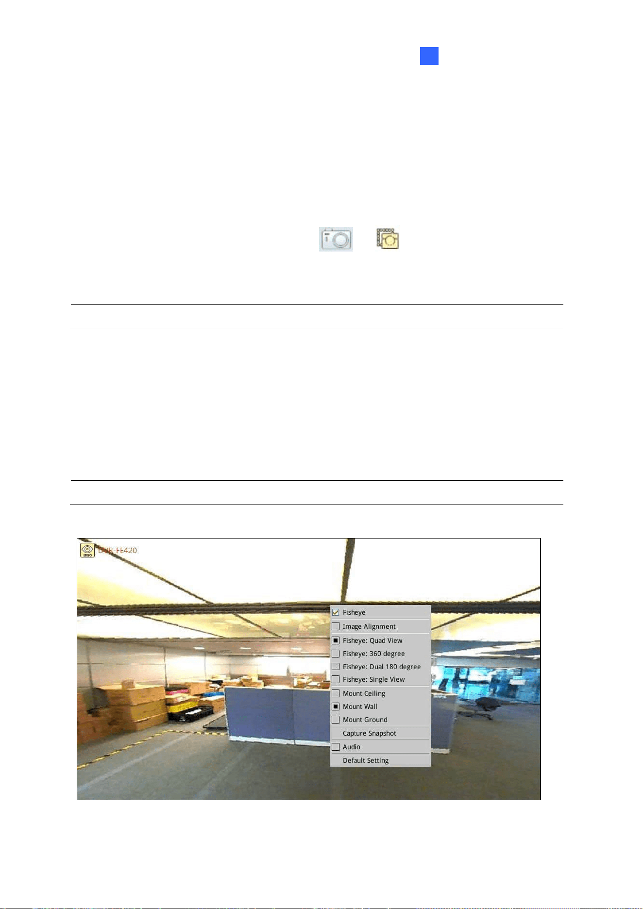
3.3 Fisheye Dewarping
You can enable fisheye dewarping if the fisheye camera is in Single View or Grid 1 of the
Quad View. Right-click the live view of the fisheye camera and select Fisheye to enable
fisheye dewarping.
Note: Fisheye dewarping is only supported by GV-IP Decoder Box Plus.

58
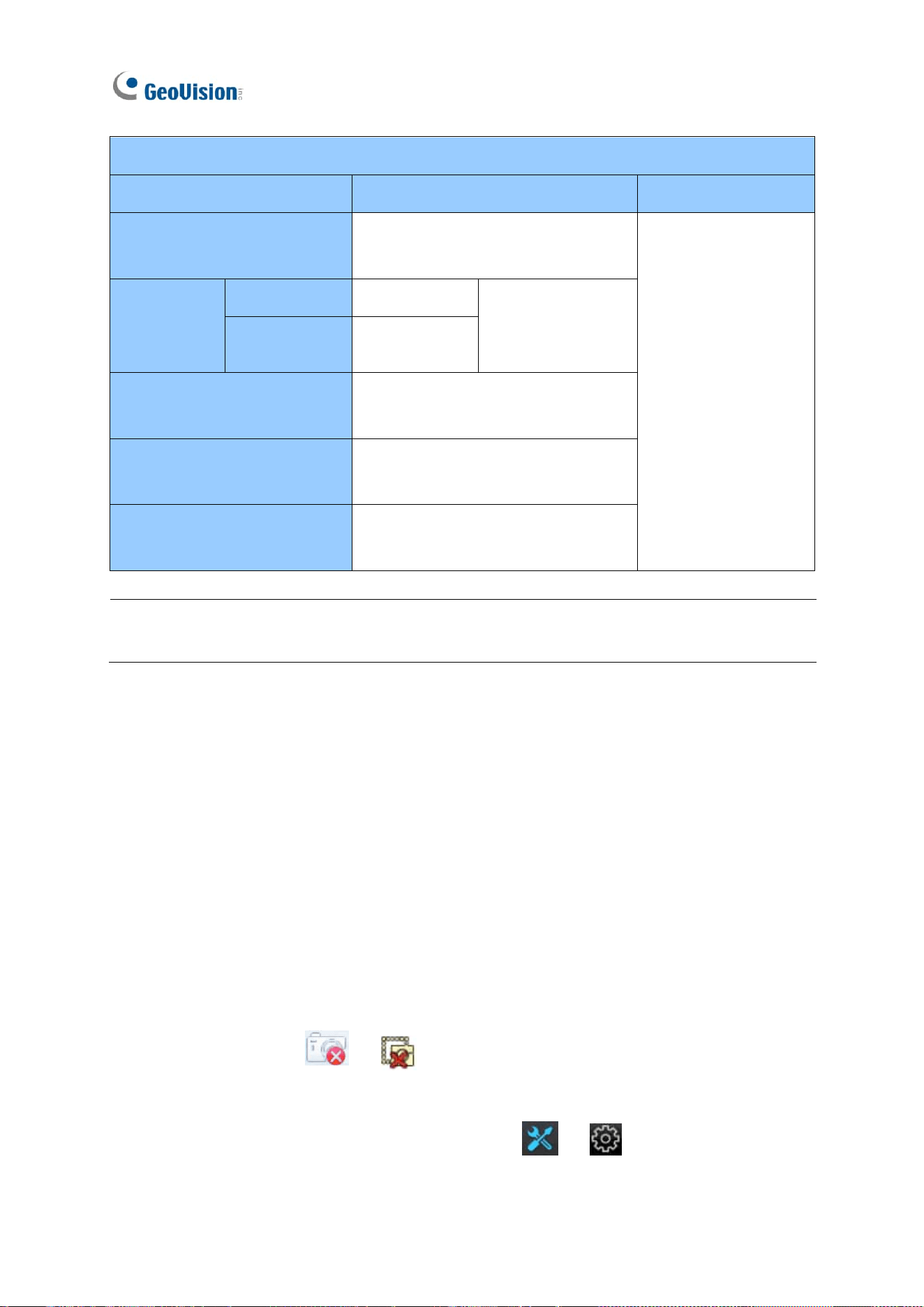
The following fisheye settings are available:
◼ Image Alignment: Align the red circle with the inner edge of the camera image if
needed. You can adjust the red circle by dragging and by scrolling the mouse.
◼ Camera Modes:
◼ Fisheye: Quad view: Composed of 3 PTZ views and a circular source image.
◼ Fisheye: 360 degree: Composed of two PTZ views and one 360º panoramic
view.
◼ Fisheye: Dual 180 degree: Composed of two 180º views.
◼ Fisheye: Single view: Composed of one PTZ view.
◼ Mount Ceiling / Mount Wall / Mount Ground: Select according to where the camera is
mounted.
Accessing Live View
59
3
3.4 Controlling PTZ and Speed Dome Cameras with
GV-Joystick V2
GV-Joystick V2 can be connected to GV-IP Decoder Box series / GV-Pad Mini / GV-IP
Display series to control GeoVision or third-party PT, PTZ, and Speed Dome cameras. The
supported functions include zoom in, zoom out, tilt (vertical movement), pan (horizontal
movement), focus in, focus out, and automatic focus. The functions corresponded to each
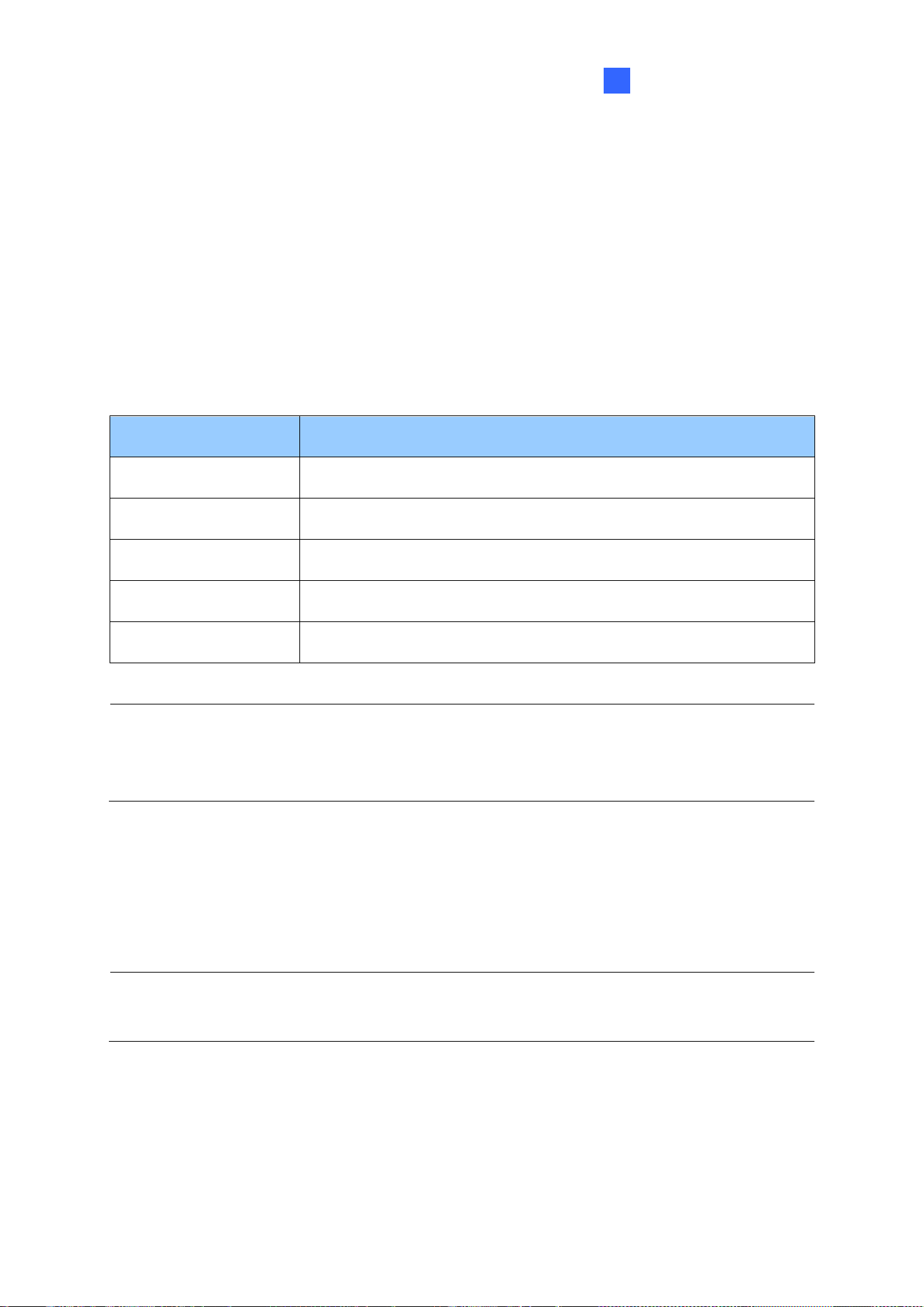
button on GV-Joystick V2 are listed below:
Button
Function
F1
Focus In
F2
Focus Out
F3
Auto Focus
F4
Home
F5 / F6
No functions
Note: For PTZ control, GV-SD200 and third-party cameras must be connected through
ONVIF. GV-Joystick V2 cannot control channels connected through GV-Mobile Server or
RTSP.
1. Connect a GV-Joystick V2 to the USB port.
2. Right-click the live view of the PTZ device and select PTZ.
3. Start to control the camera using GV-Joystick V2.
Note: For GV-IP Decoder Box Mini / Optimal / Ultra, you can also use GV-IR Remote
Control to control PTZ movements. See 1.11.3 GV-IR Remote Control.
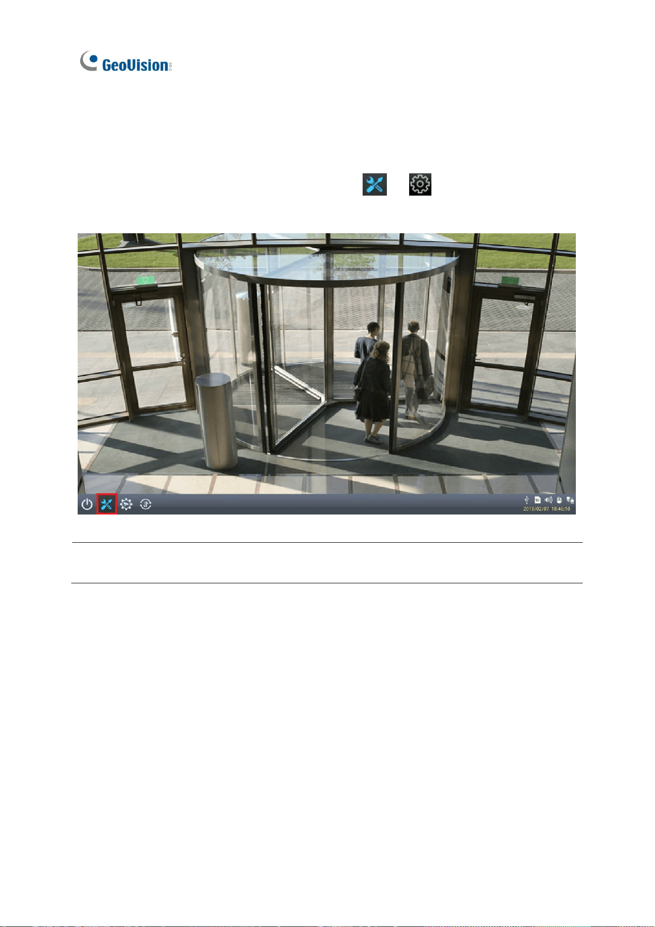
60
Chapter 4 System Settings
On the main screen, click the System Settings icon or to access the following
setting pages: System, Network, Date & Time, Account, Display, and Camera.
Note: The main screen may vary slightly by model. Here we use GV-IP Decoder Box Ultra /
GV-IP Display 101 as an example.
System Settings
61
4
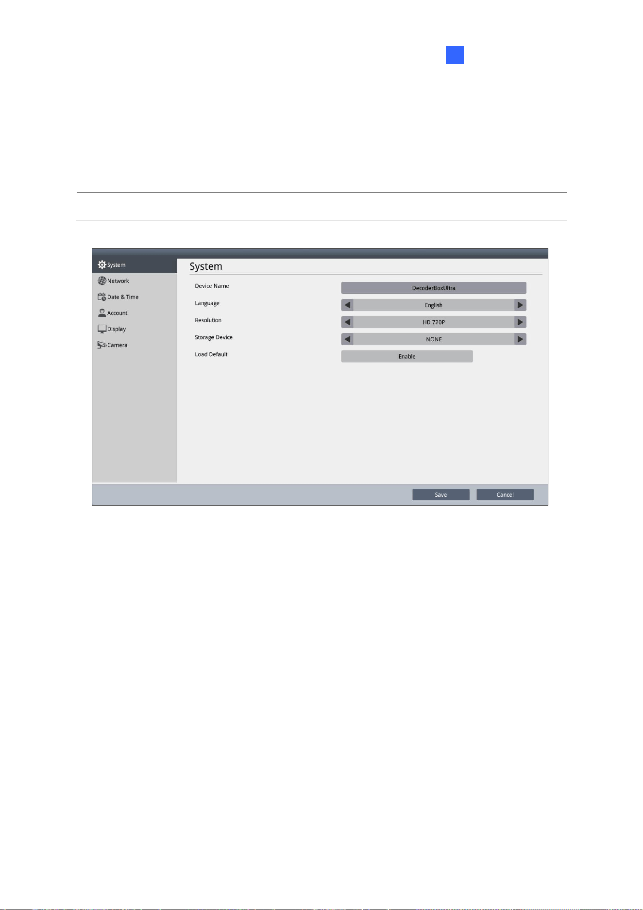
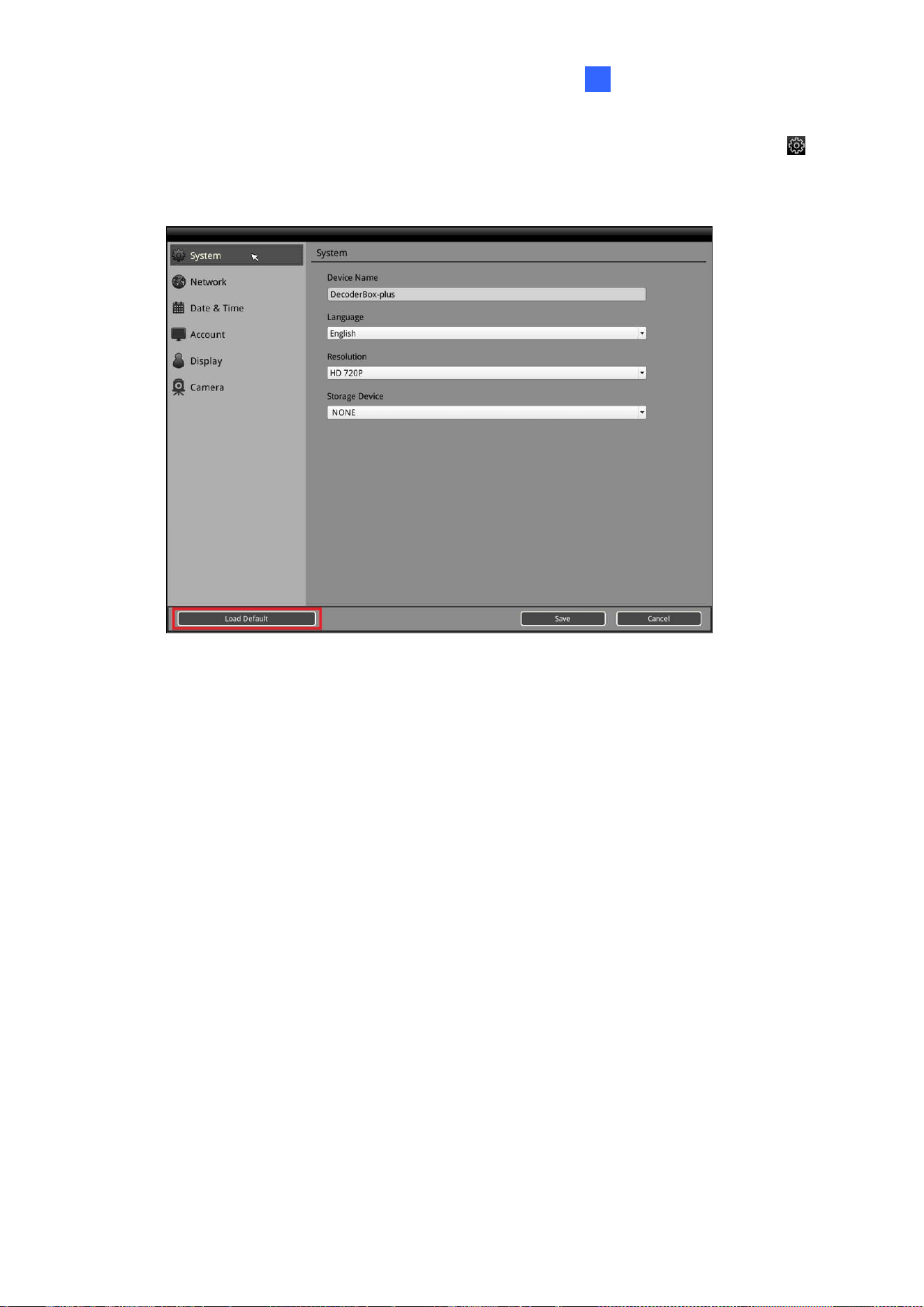
4.1 System
On the System page, you can change the device name, interface language, resolution, or the
designated storage device for storing snapshots.
Note: Capturing snapshots is not supported by GV-IP Decoder Box Lite.
◼ Device Name: Click to change the device name.
◼ Language: Select a language for the user interface.
◼ Resolution: Only for GV-IP Decoder Box series, select a resolution for your monitor.
The default is HD 720P. If you are using a VGA monitor, select VGA 1024 x 768 / HD
1080P.
◼ Remote Assistance: Only for GV-IP Decoder Box Mini / Optimal. This option allows
technical staff to perform remote debugging.
◼ Storage Device: Select the storage device you want to use for storing captured
snapshots.
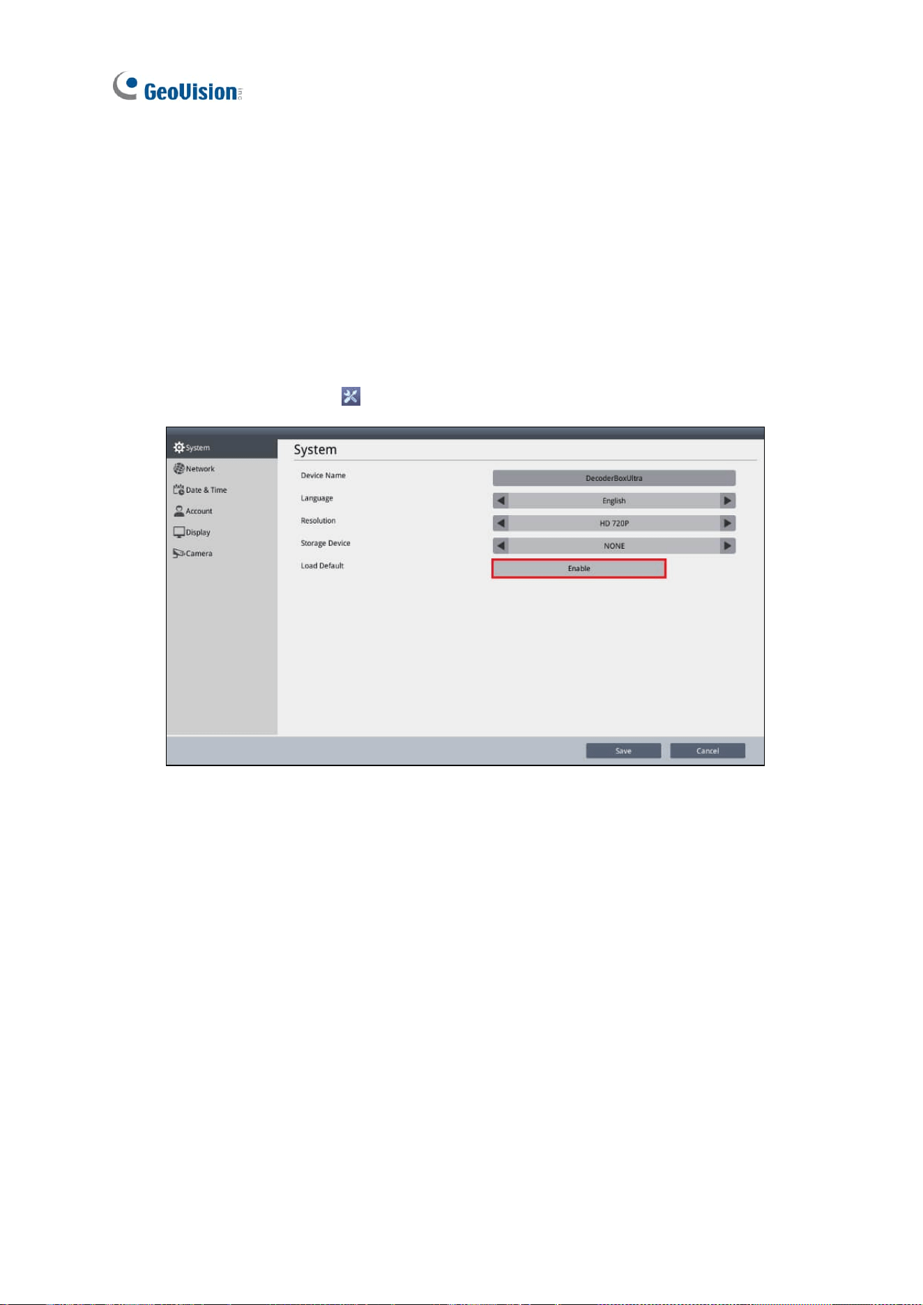
◼ Load Default: Only for GV-IP Decoder Box Mini / Optimal / Ultra / GV-IP Display 101 /
116, click Enable to restore the device to default settings. For details, see 5.2 Restoring
Default Settings.
Click Save to apply the settings.
62
4.2 Network
To configure the network settings for GV-IP Decoder Box series / GV-Pad Mini / GV-IP
Display series, see 2.5 Setting Up the Network.
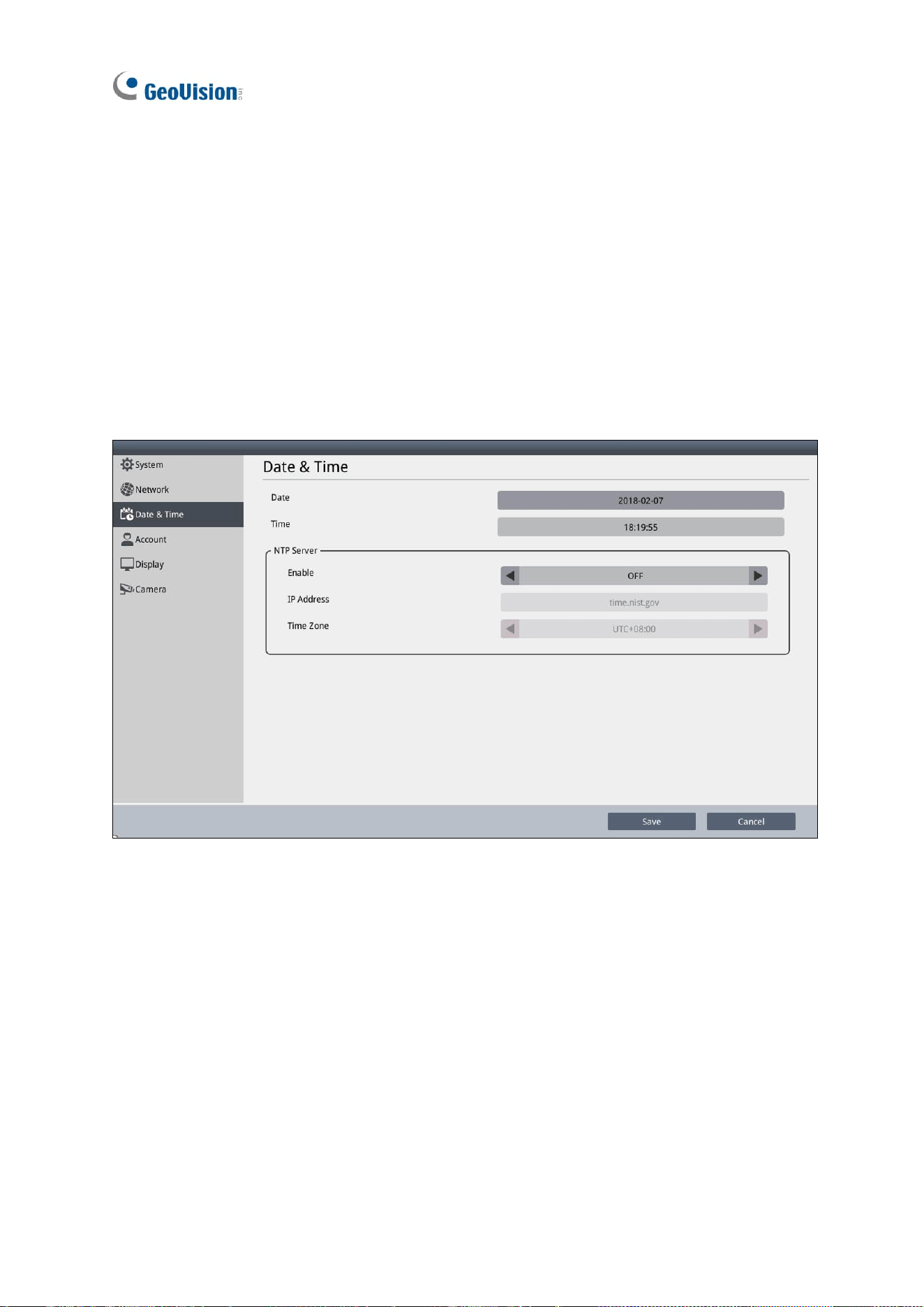
4.3 Date & Time
On the Date & Time page, you can configure the date and time of GV-IP Decoder Box series /
GV-Pad Mini / GV-IP Display series.
◼ Date & Time: Click to adjust the date and time.
◼ NTP Server: Switch the Enable option to ON or Select Enable NTP and type the URL
of a network time server to synchronize the clock with the network time server.
◼ Time Zone: Select a time zone for your location.
Click Save to apply the settings.
System Settings
63
4
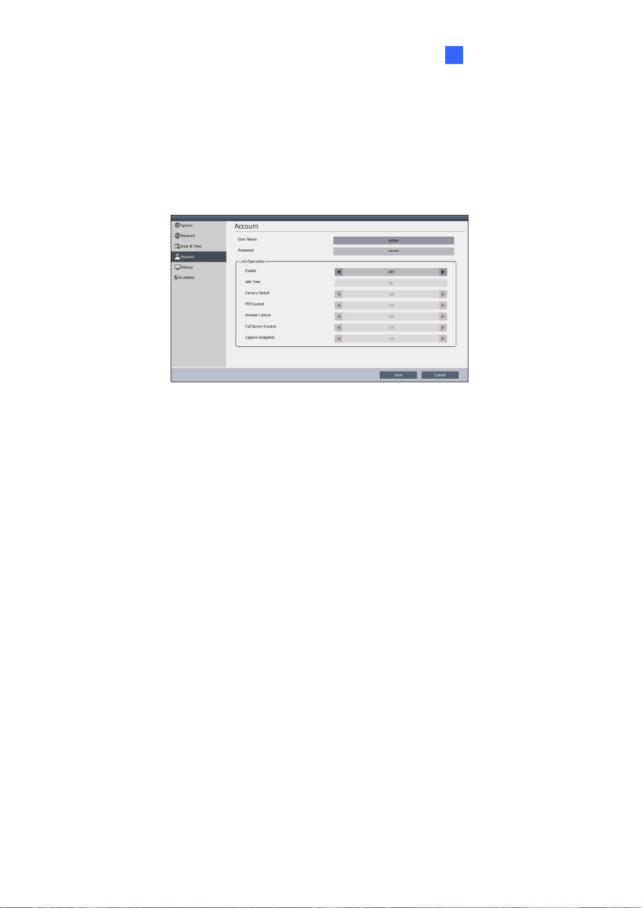
4.4 Account
On the Account page, you can configure the login account for GV-IP Decoder Box series /
GV-Pad Mini, and GV-IP Display series. You will need the login information if you want to
access the listed Decoder Box, Pad or Display through GV-IP Device Utility.
To configure the screen lock, enable the following function to manage users’ accessibility.
After enabling the function, you must enter the username and password if the device has
been idle for a specified time.
◼ Lock Operation (for GV-IP Decoder Box Mini / Optimal / Ultra / GV-IP Display 101 / 116)
Login window (for GV-IP Decoder Box Plus / Lite / GV-Pad Mini)
◼ Idle / Wait Time: Specify an idle time from 30 to 300 seconds.
Only for GV-IP Decoder Box Mini / Optimal / Ultra / Plus / GV-Pad Mini / GV-IP Display 101 /
116, you can specify the following functions to be locked or unlocked after the specified time.
Entering the username and password again can unlock the functions.
◼ Camera Switch / Lock Play Control
◼ PTZ Control / Lock PTZ Control
◼ Volume Control / Lock Audio Control
◼ Full Screen Control / Lock Full screen
◼ Capture Snapshot / Lock Capture Snapshot
◼ Lock Dewarp Control (only available for GV-IP Decoder Box Plus)
◼ Video Rotate (only available for GV-IP Decoder Box Mini / Optimal / GV-IP Display 116)
◼ Video Flip (not available for GV-IP Decoder Box Mini / Optimal / GV-IP Display 116)
64
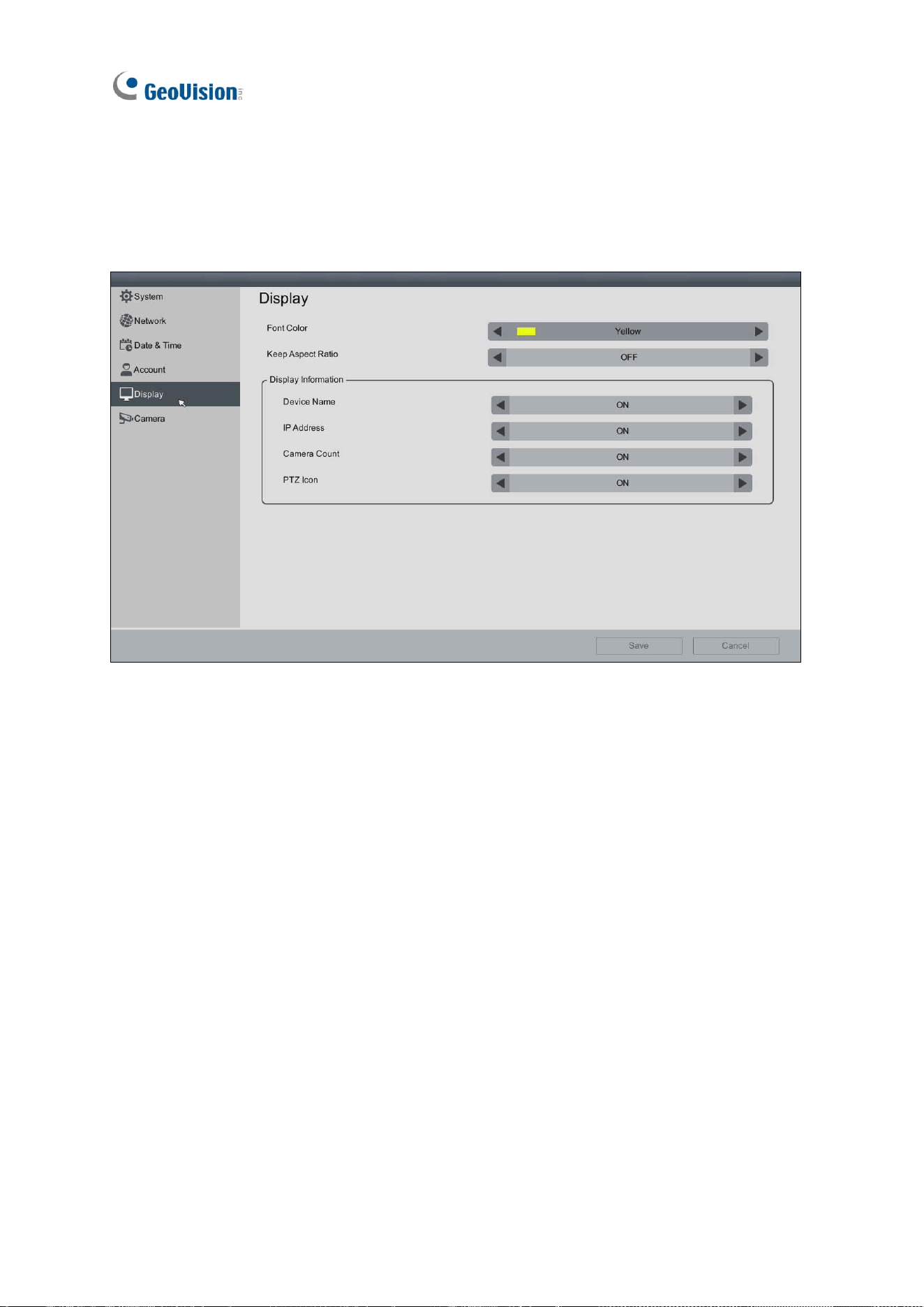
4.5 Display
On the Display page, you can adjust the orientation of the live view and specify what
information to overlay on the live view.
◼ Font Color: Change the font color of the text overlay.
◼ Keep Aspect Ratio: For GV-IP Decoder Box Mini / Optimal / Ultra (V1.05 or later), and
GV-IP Display 101 (V1.01 or later) / 116, select ON to avoid enlarging the live view
image to fit your screen size. This applies to all cameras connected.
◼ Device Name / Display Name: Select to display the device name of the camera.
Camera Name: Select to display the camera name.
Custom Name: Select to display the personalized camera name.
◼ IP Address / Display IP Address: Select to display the IP address of the camera on
the live view.
◼ Camera Count / Display Camera Count: Select to display the camera count of the live
view grid. For example, 7/8 indicates that there are 8 cameras assigned to the live view
grid, and live view of the 7
th
camera is currently being displayed.
◼ PTZ Icon / Display PTZ Icon: Select to display a PTZ icon when the camera supports
PTZ functions.
System Settings
65
4
◼ Extend Screen: Only for GV-IP Decoder Box Optimal. Select Enable to cast the
cameras’ live view in single-division mode on the VGA-connected monitor. When
disabled, the live view from the HDMI-connected monitor will be mirrored to the VGA
monitor simultaneously.
◼ Loop Time Interval: Specify a time interval, ranging from 10 ~ 600 seconds, for the
camera to display before switching to the next one when Extend Screen is enabled.
The default value is 10 seconds.
Click Save to apply the settings.
Note: After enabling / disabling the Extend Screen function, the device will reboot.
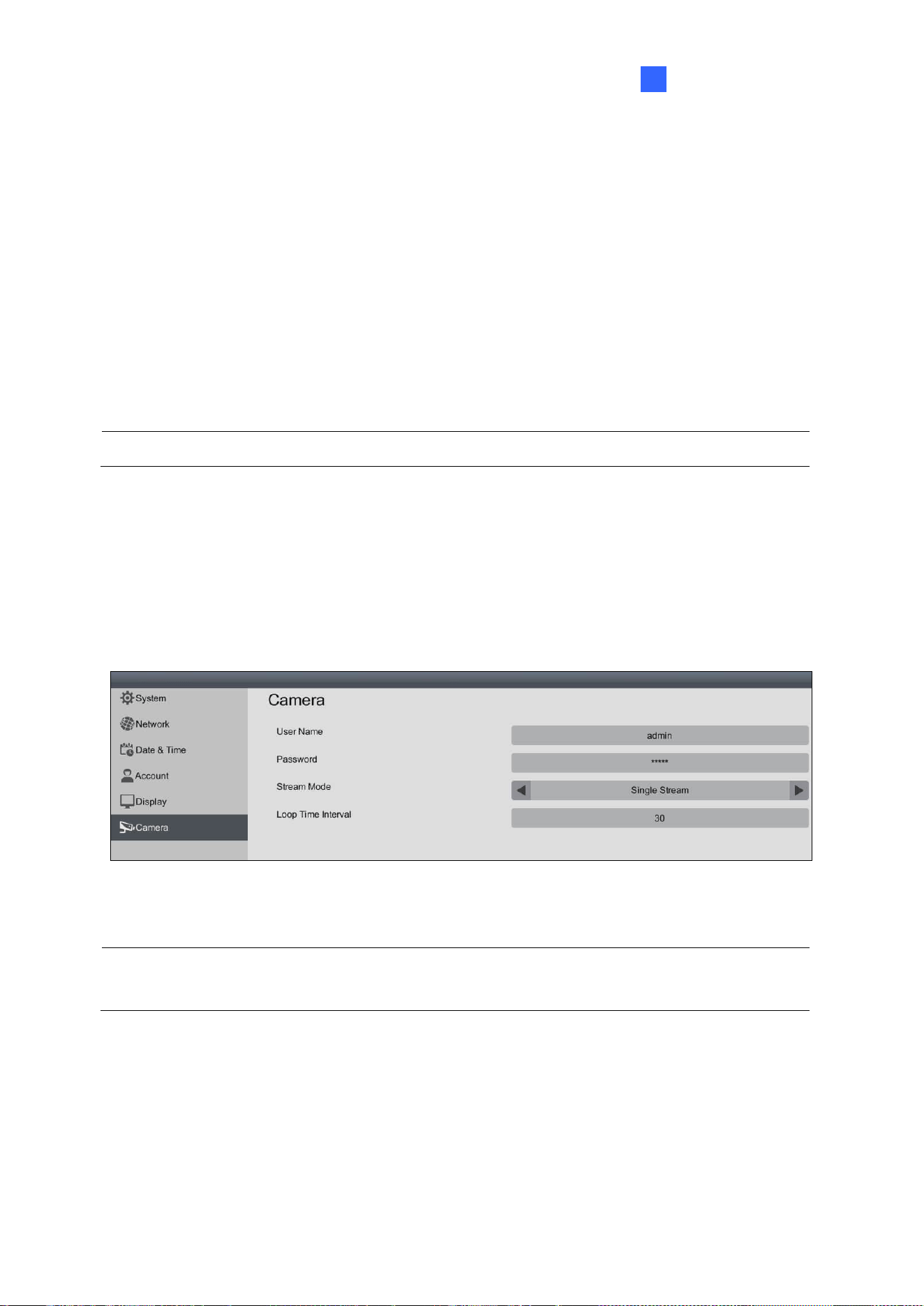
4.6 Camera
On the Camera page, you can specify an ID, password, stream mode and loop time interval
to all newly-added IP devices. By default, username and password both are admin and
stream mode is Dual Stream.
Click Save to apply the settings.
Note: The stream mode and loop time interval functions are only available in GV-IP Decoder
Box Mini / Optimal / Ultra, and GV-IP Display 101 / 116.
66
Chapter 5 Advanced Applications
5.1 Upgrading the Firmware
GeoVision will periodically release firmware updates on the website. You can upgrade
firmware locally using a USB drive or SD card, or remotely through GV-IP Device Utility.
Note: The SD card is not supported by GV-IP Decoder Box Lite.
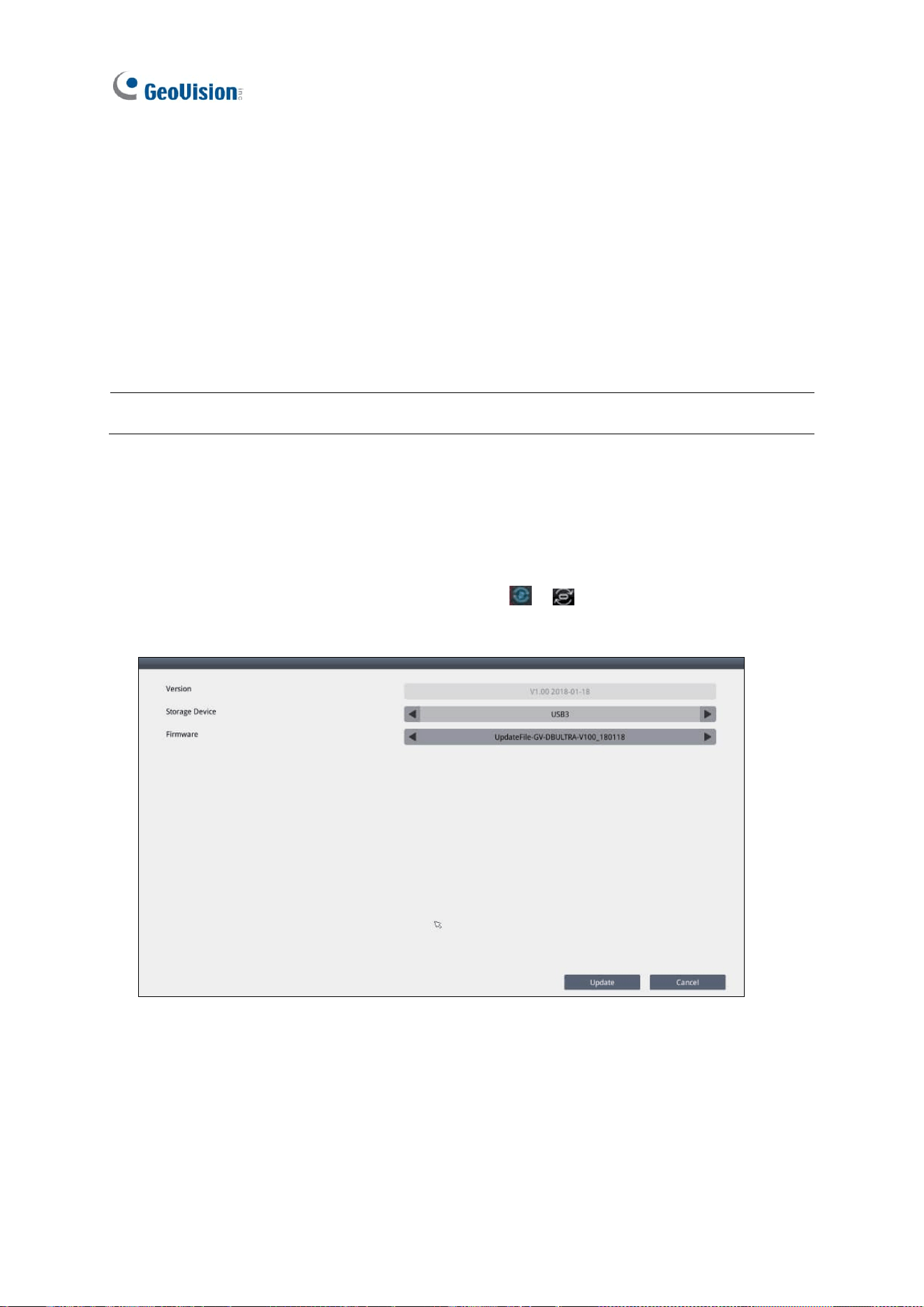
5.1.1 Upgrading Firmware through a Storage Device
1. Copy the firmware file to the root folder of a USB drive or an SD card.
2. Insert the storage device to a Decoder Box or Display.
3. On the main screen, click the Firmware Update / icon.
4. Select the storage device and select the firmware file.
5. Click Update to begin upgrading the firmware. The Decoder Box or Display will restart
after the firmware upgrade is completed.
Advanced Applications
67
5
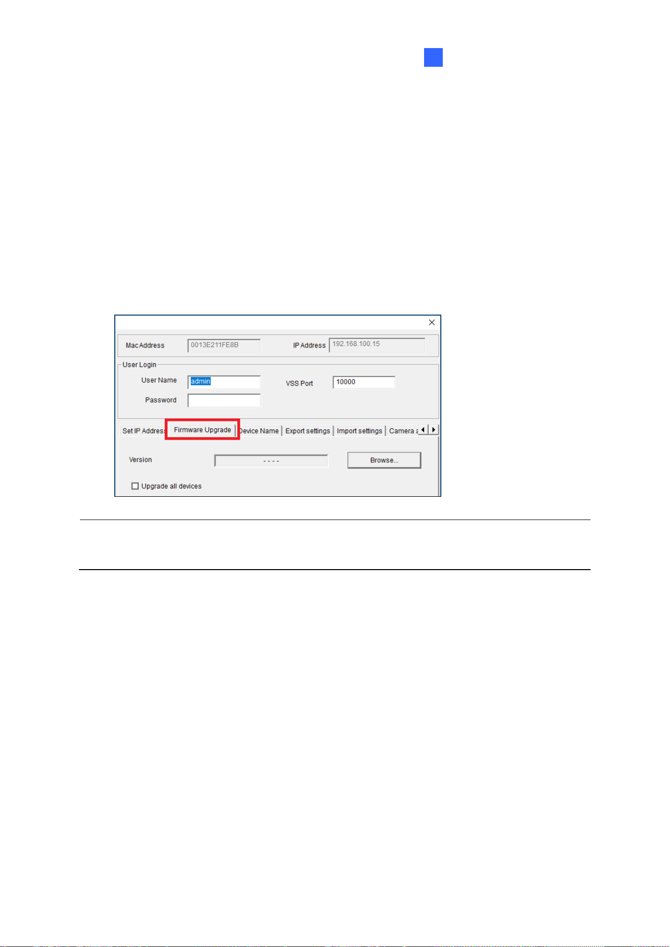
5.1.2 Upgrading Firmware through GV-IP Device Utility
1. Run GV-IP Device Utility. Once started, the utility will automatically search for GV
devices connected on the same LAN.
2. Double-click the desired device in the list and select the Firmware Upgrade tab.
3. Click Browse to locate the firmware file saved on your local PC.
4. Type the username and password of the device under User Login.
5. Optionally, select Upgrade all devices to update the firmware of the devices, with the
same username, password and model, in the list.
6. Click Upgrade. The system will restart itself when the upgrade is completed.
Note: To see how to change the login information of the Decoder Box or Display, see 4.4
Account.
68
5.2 Restoring Default Settings
If for any reason GV-IP Decoder Box series / GV-Pad Mini / GV-IP Display series is not
responding correctly, there are two ways to restore the device to default settings.
1. Use the pin to press the load default button on the front / side panel for about 10 seconds.
2. Use the local interface to configure the setting.
• For GV-IP Decoder Box Mini / Optimal / Ultra / GV-IP Display 101 / 116, click the
System Settings icon on the main page, click System, and enable Load Default.
Advanced Applications
69
5
• For GV-IP Decoder Box Plus / Lite / GV-Pad Mini, click the System Settings icon
on the main screen and click the Load Default button on the bottom of any of the
setting pages.
The system will restore default settings and reboot itself.
70
Chapter 6 Integration to GV-Software
The Decoder Box can be added to GV-VMS, GV-Control Center, and GV-Edge Recording
Manager to be assigned with the desired camera channels and layouts for remote display.
Each live view grid supports looping up to 64 cameras when the Decoder Box is integrated
with the GV-Software.
GV-IP Decoder Box and Display Compatibility
Model
Firmware
Compatible Software Versions
GV-IP Decoder Box Mini
V1.00
- GV-VMS V17.4.8 / V18.3.3 or later
- GV-Control Center V4.2.1 or later
- GV-Edge Recording Manager V2.3.0 or later
GV-IP Decoder Box Optimal
V1.02
- GV-VMS V17.4.8 / V18.3.3 or later
- GV-Control Center V4.2.1 or later
- GV-Edge Recording Manager V2.2.8 or later
GV-IP Decoder Box Plus
V1.02
GV-VMS V17.4.0 only
GV-IP Decoder Box Ultra
V1.09
- GV-VMS V17.4.0 / V18.1.0 or later
- GV-Control Center V3.8.0 / V4.2.0 or later
- GV-Edge Recording Manager V2.2.8 or later
Note: Make sure the Decoder Box is on the same LAN as the software you wish to connect
to.
Integration to GV-Software
71
6
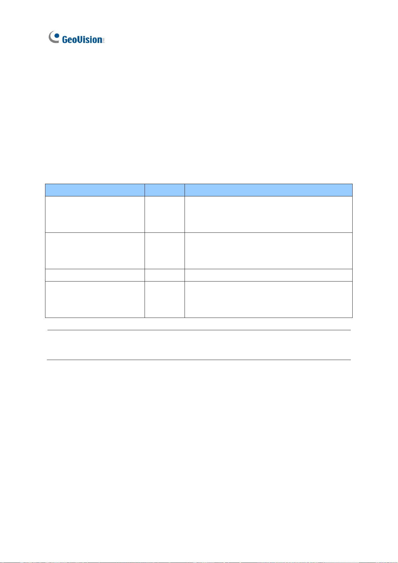
6.1 Connecting to GV-VMS
To connect the Decoder Box to GV-VMS, follow the steps below:
1. In the Content List of GV-VMS, (Home > Toolbar
> Content List), right-click
Decoder Box > Add Decoder Box.
2. Type a desired Name for the Decoder Box you’re connecting to, its IP Address, Port, ID
and Password, and click OK to add it to GV-VMS.
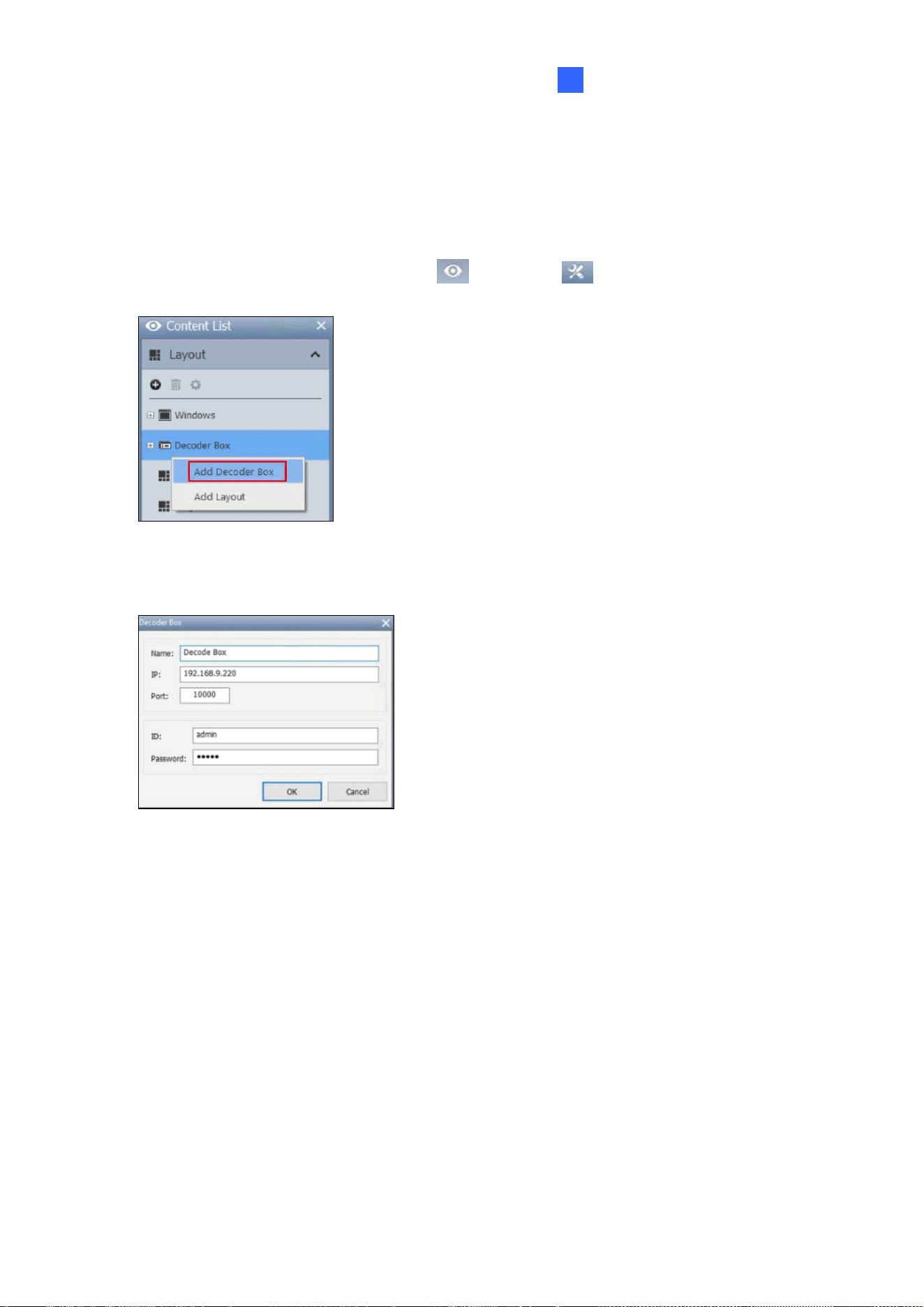
3. Once added, you’re prompted to set a layout. Click OK. The Layout Setup dialog box
appears.
72
4. Select a desired layout from the top, and drag the desired camera channels from GV-VMS
into each layout division. When multiple camera channels are assigned to the same
division, their live views will be displayed sequentially within that division.
5. To adjust a camera’s order within a division or remove it, use the Up , Down or
Delete buttons.
6. Click OK. The Decoder Box will display the camera channels as configured.
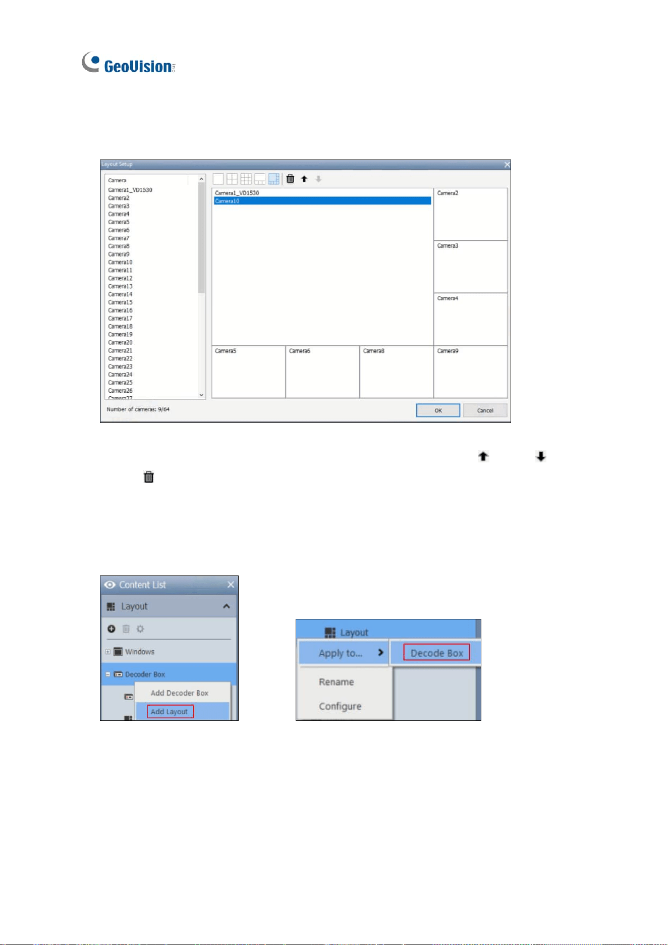
7. To add more layouts and alternate between them, right-click Decoder Box in the Content
List > Add Layout. To apply a layout, right-click a layout > Apply to… and select a
Decoder Box.
Integration to GV-Software
73
6
6.2 Connecting to GV-Control Center / GV-Edge Recording
Manager
6.2.1 Decoder Box Display through Video Wall
To create a layout for the Decoder Box in GV-Control Center or GV-Edge Recording Manager,
follow the steps below. These instructions are based on GV-Control Center V4.2.1.
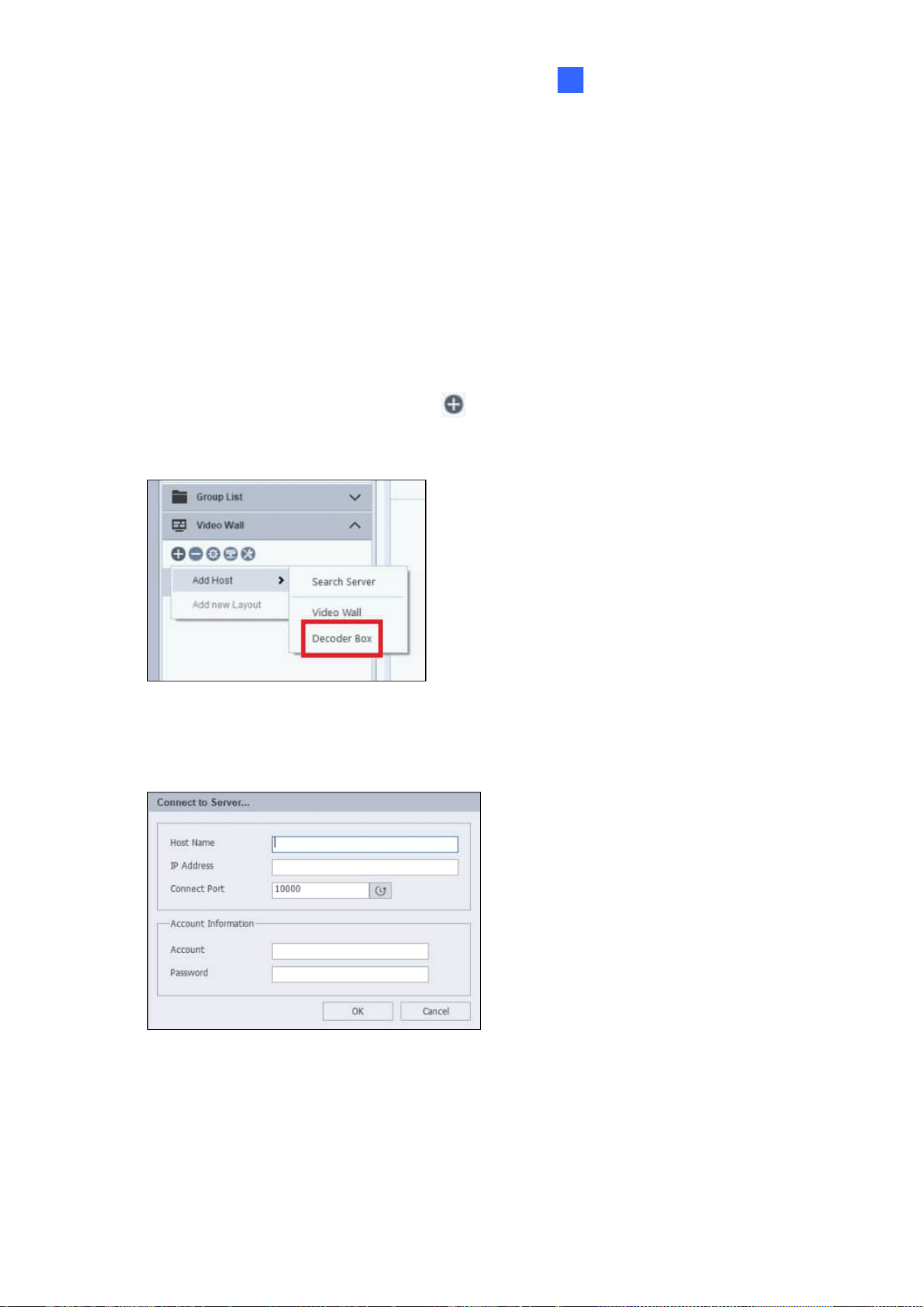
1. Open the Video Wall list and click the button to add a host.
2. Select Add Host > Decoder Box.
3. Type the Host Name, IP Address, Connection Port, Account, and Password for the
Decoder Box. Click OK.
74
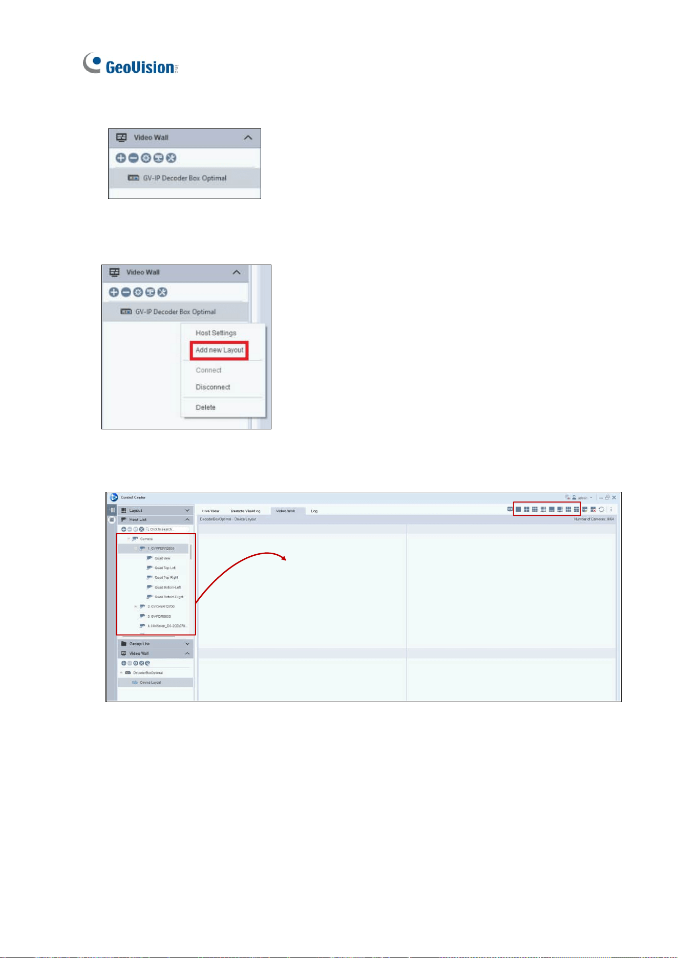
4. Once connected, the Decoder Box appears in the Video Wall list.
5. Right-click on the Decoder Box > Add new Layout.
6. Select a layout from the top right corner, and drag the desired camera channels into each
layout division.
The Decoder Box’s monitor now displays the camera channels as configured.
Integration to GV-Software
75
6
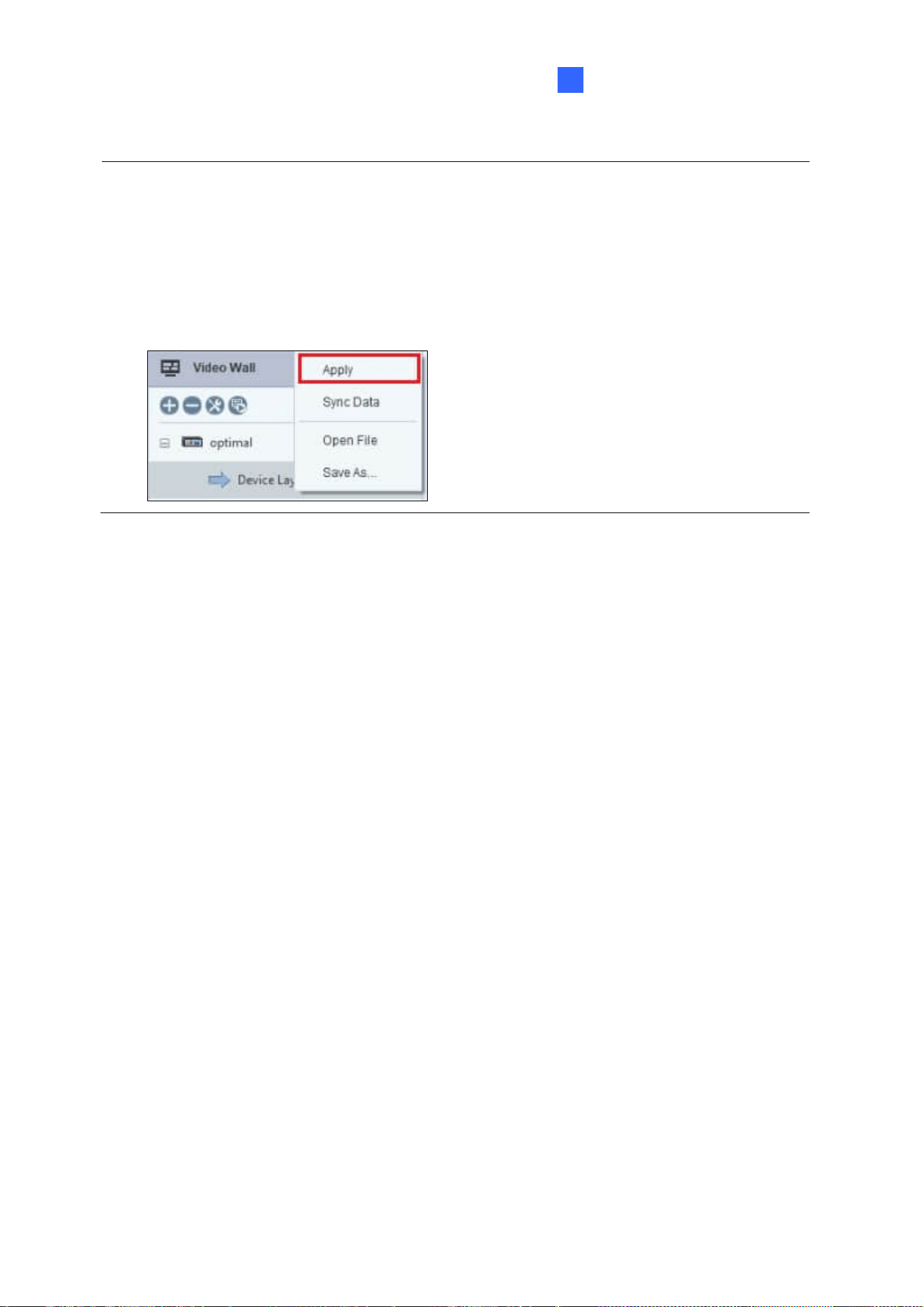
Note:
1. The Decoder Box automatically adjusts its display layout based on the number of
cameras. For example, if a 9-division layout is applied in GV-Control Center but only
one camera is streamed, the Decoder Box displays it in full screen. With two cameras,
the display switches to a 4-division layout.
2. For any changes to take effect, right click on the Device Layout > Apply.
76
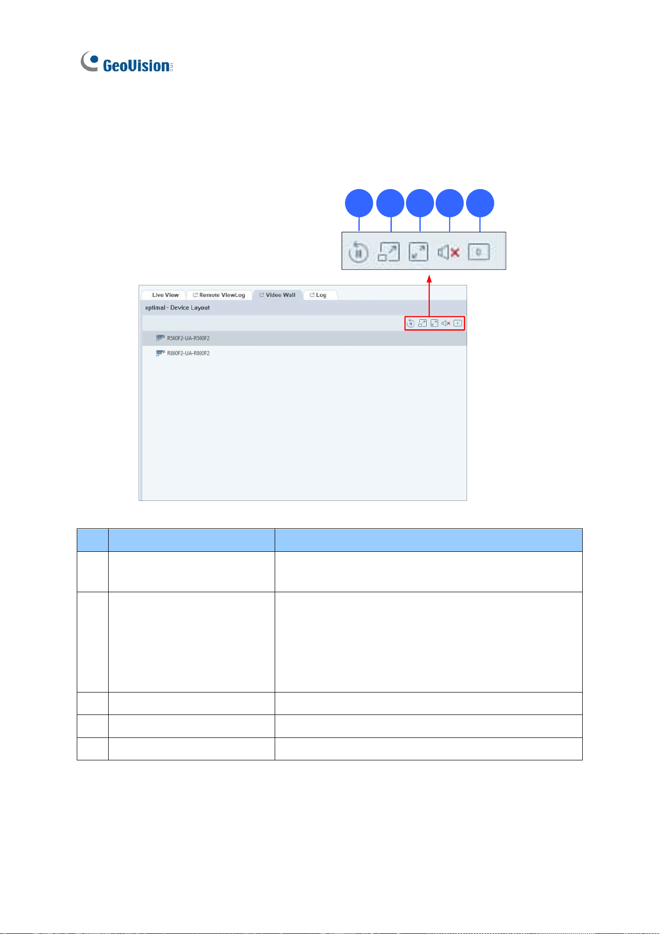
Remote Control on GV-Control Center
You can remotely configure the Decoder Box display settings on GV-Control Center. The
interface is as shown below:
1 2 3 4 5
No.
Name
Function
1.
Play / Pause Loop
Click to play or pause the loop when multiple IP cameras
are added under the same channel.
2.
Extend to 2nd screen
The function is only for GV-IP Decoder Box Optimal.
When the Extend Screen function is enabled, select this
option to loop camera channels to the VGA-connected
monitor in single-division mode. To enable Extend
Screen, see Note 1 below.
3.
Zoom
Select to display the channel in full screen.
4.
Volume / Mute
Select to mute the channel or adjust the volume.
5.
Video Rotate
Select to rotate the live view image in 90°, 180°, or 270°.
Integration to GV-Software
77
6
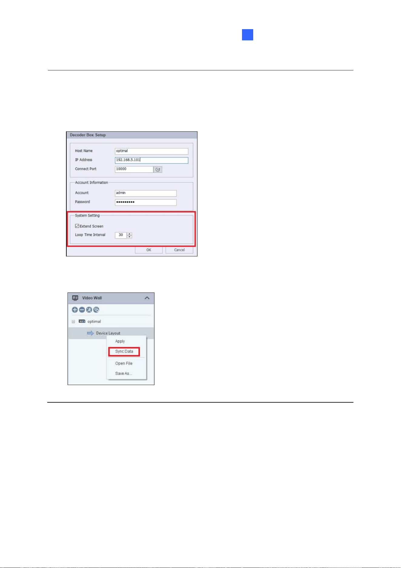
Note:
1. To enable the Extend Screen function from GV-Control Center, right-click on a GV-IP
Decoder Box model in the Host List > Host Settings. Select Extend Screen and set
the loop time interval.
2. To apply the changes made on the Decoder Box, right-click on Device Layout > Sync
Data.
78
6.3 Dynamic Alerts via Control Center E-Map
When a GV-Control Center’s E-Map is linked to a GV-IP Decoder Box Optimal:
• Motion events on a camera will automatically trigger the associated video channel
to display on the Decoder Box’s monitor.
• Users can also manually select and display E-Map channels on the Decoder Box’s
monitor.
Note: The E-Map applications only work with GV-IP Decoder Box Optimal (firmware V1.02
or later) and GV-Control Center (V4.2.1 or later).
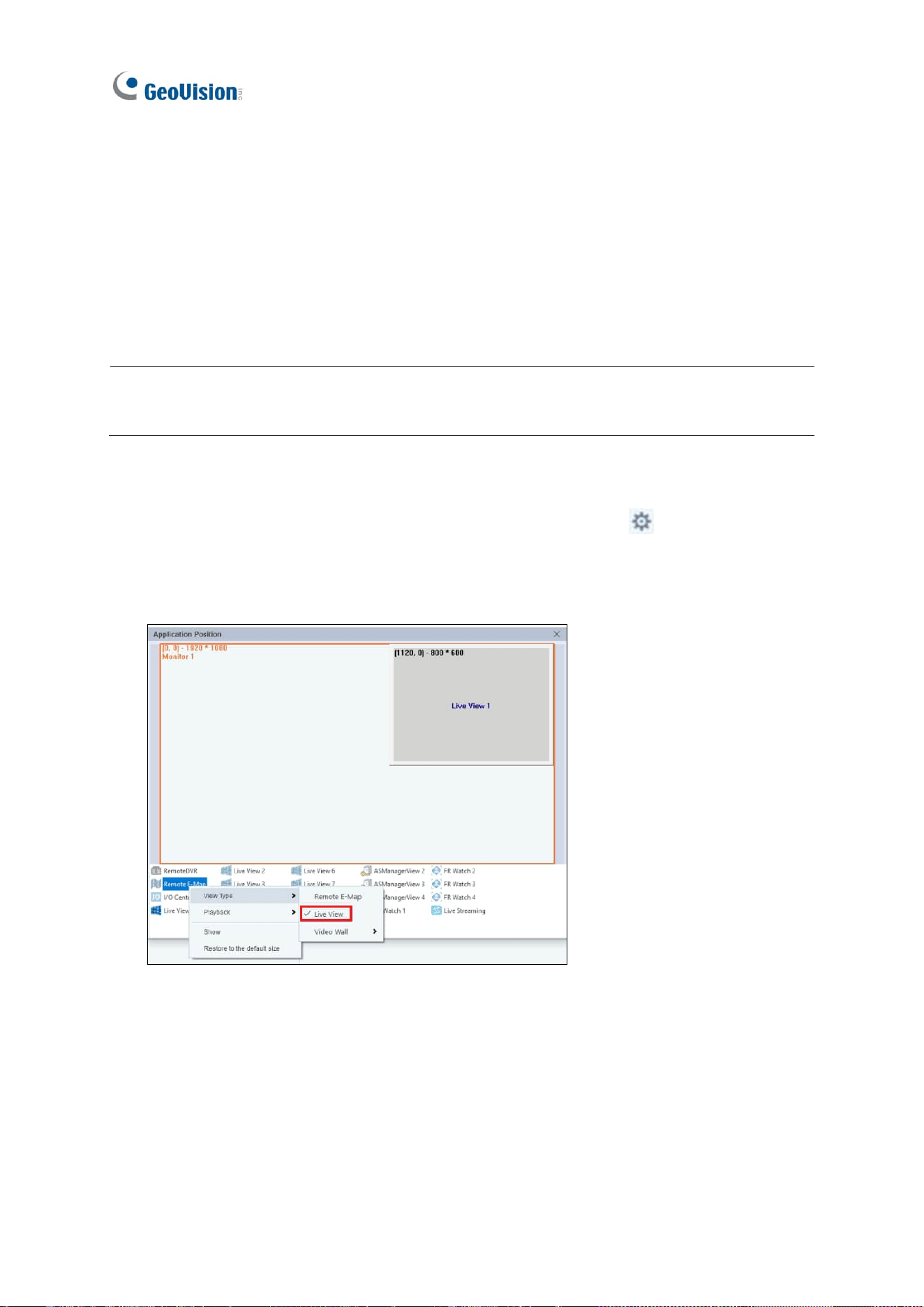
To set up:
1. On the top right corner of GV-Control Center, select Configure > Setup >
Application Position. The Application Position window appears.
2. Right-click on Remote E-Map, and change the View Type to Live View.
Integration to GV-Software
79
6
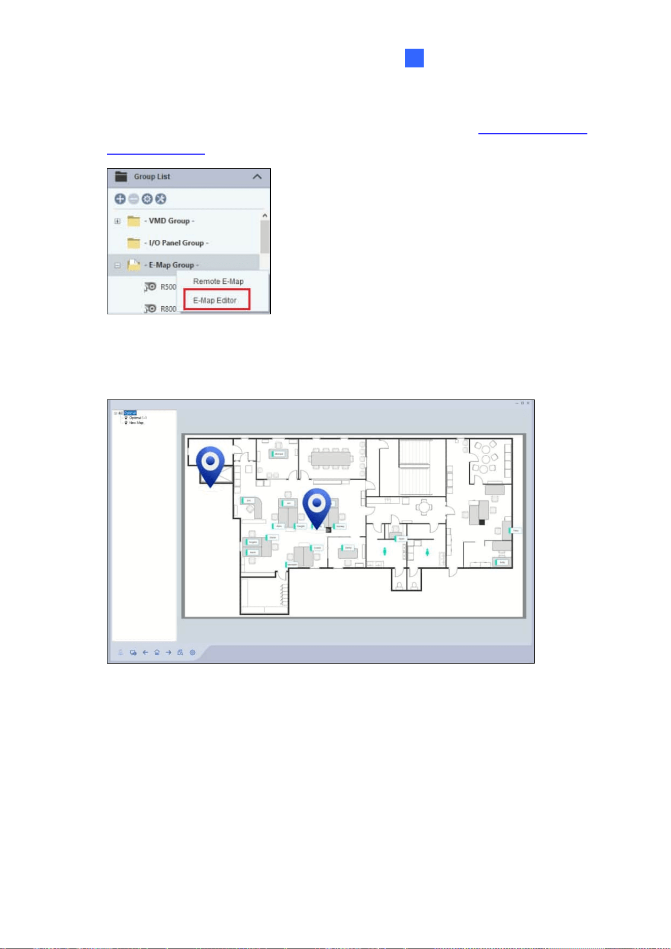
3. To create an E-Map, right-click E-Map Group under the Group List > E-Map Editor. For
details to use the E-Map Editor, see Chapter 9 Other Applications in GV-Control Center
V4 User’s Manual.
4. When the E-Map file is created, right-click on E-Map Group under the Group List >
Remote E-Map. The Remote E-Map window appears.
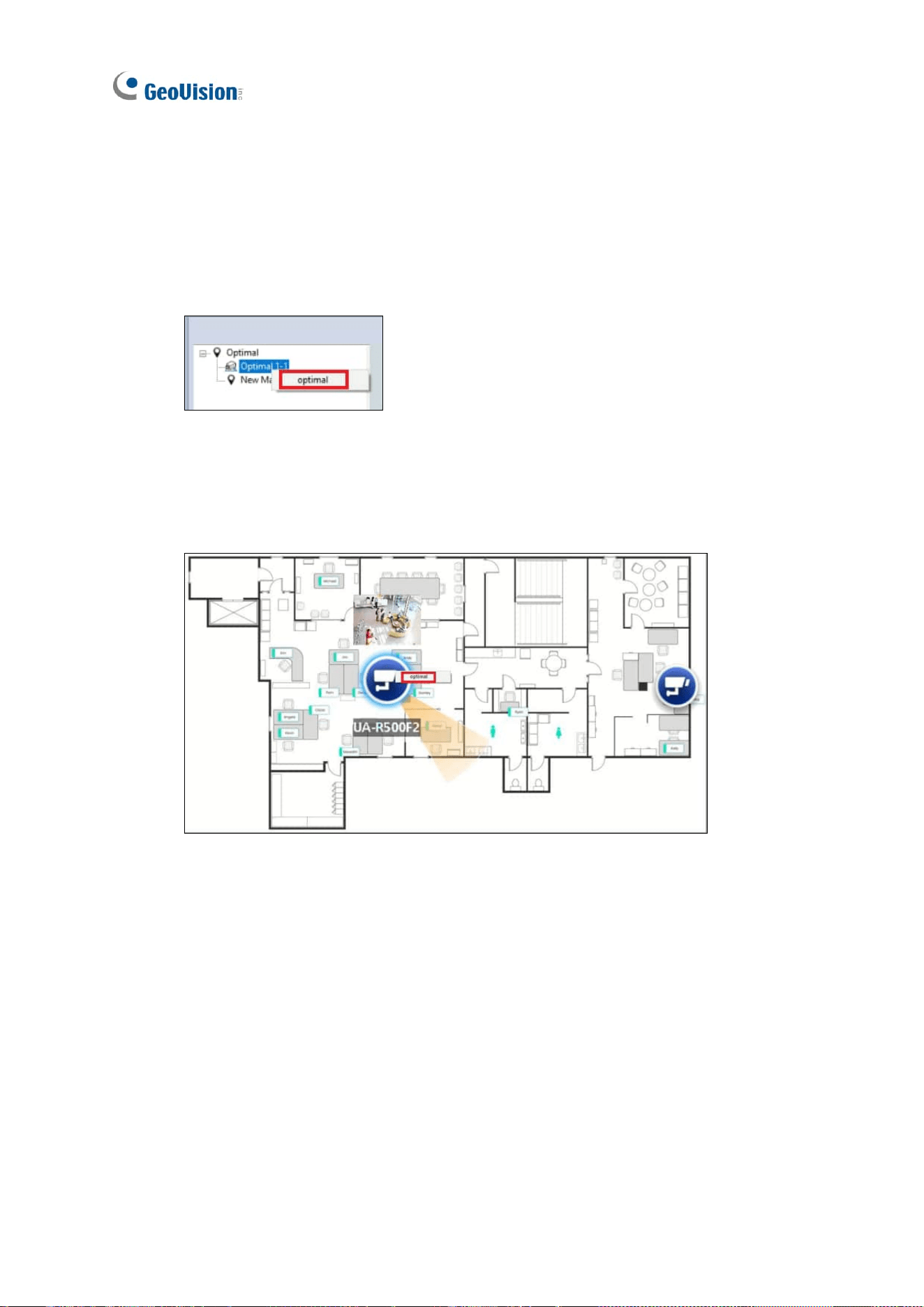
80
You can choose to automatically cast channels upon motion events or manually assign
individual channels to the Decoder Box’s monitor.
◼ To cast channels upon motion events: On the tree list on the left, right-click on
the desired map file and select the Decoder Box you wish to cast the channels to.
When motion events occur, the associated camera or icon on the E-Map will flash,
and the channels will be automatically cast onto the Decoder Box’s monitor.
◼ To cast individual channels: Right-click on the desired camera and select the
Decoder Box you wish to cast the channel to. The selected channels will be cast
onto the Decoder Box’s monitor.