
User Guide
Power Management with Control System
M4320-PRO

Contents
Introduction .................................................................................3
Before You Begin Inspect Upon Receipt .............................................................3
Features Descriptions ..........................................................................4
Important Safety Instructions .....................................................................5
Front Panel Features Overview....................................................................5
Preset Prole Information .......................................................................6
Rear Panel Features Overview ....................................................................7
The Bubble of Protection ........................................................................7
Getting Setup for BlueBOLT ......................................................................8
BlueBOLT Online Registration.....................................................................8
Troubleshooting ..............................................................................8
Identify Connected Equipment ....................................................................9
Telnet/ Protocol Specication.....................................................................10
M4320-PRO Specications . . . . . . . . . . . . . . . . . . . . . . . . . . . . . . . . . . . . . . . . . . . . . . . . . . . . . . . . . . . . . . . . . . . . . . 15
FCC Notice ..................................................................................16
Contacting Customer Service.....................................................................16
2
Introduction
Thank you for purchasing a Nice M4320-PRO Power Management with control system interactive functionality, and congratulations on your choice. The
M4320-PRO features Nice’s revolutionary AVM (Automatic Voltage Monitoring) circuit, and our exclusive Linear Filtering Technology (LiFT). Together, these
technologies comprise precisely what our customers have come to expect from Nice: uncompromised AC protection and purication. Outlets: all rear panel
outlets are separately controlled. They are grouped into four (4) lter-isolated banks. BlueBOLT™ is included, providing secure, hosted IP system control
and monitoring for the M4320-PRO.
Before You Begin Inspect Upon Receipt
Box should contain the following, including the Quick Start Guide:
1. M4320-PRO
2. Four silicone rubber feet for shelf mounting.
3. Four Phillips pan head screws with cup washers for rack mounting.
Power Management with Control System Interactive Functionality.
• 20 Amp Capacity M4320-PRO
• 8 Individually Controllable Rear Panel Outlets
• Fully Programmable
• TCP/IP (BlueBOLT) Installed
• Linear Filtration with 3 Isolated LiFT Filter Banks, 76db (5 kHz - 250 kHz), 46 db (250 kHz - 1 MHz)
• One Isolated Filter Bank for High Current Devices, 60db (5 kHz - 450 kHz), 46 db (450 kHz - 1 MHz)
• Front Panel Circuit Breaker
• Removable Front Rack Ears
• 12 Volt Input Triggering
• Detachable 10 ft. Power Cord - 20A plug
• AVM & Protect-or-Disconnect Circuitry
Important: You will need the BlueBOLT-CV3’s unique MAC address and challenge key (provided on the 2 labels
attached to the cover of the Quick Start Guide which is included in the M4320-PRO packaging). One label is
permanently adhered to the Quick Start Guide and the other is removable for your convenience.
3
VOLTS
OUTLET STATUS
UNSAFE VO LTAGE
ALWAYS ON
20A
BREAKER
WIRING FAULT
TEMPERATURE
VOLTS/AMPS
BRIGHTNESS
1 2 3 4 5 6 7 8
REBOOT 1 REBOOT 2
M4320-PRO
ENABLED

Features Descriptions
BlueBOLT
Remote Power Management technology provides secure, hosted IP
(Internet Protocol) system control. With BlueBOLT, custom electronics
installers, integrators and end-users can remotely monitor and control power to
home theater equipment by accessing power management components from
anywhere in the world. From simple system reboots to comprehensive monitoring
of power status, BlueBOLT
provides the power to control complex A/V systems
from their most fundamental level: their power source (M4320-PRO).
LiFT Technology EMI/RFI Noise Filtration
Your audio/video components are constantly being bombarded by electromagnetic
interference (EMI) and radio frequency interference (RFI) through their AC power
source. This contaminated power can affect audio/video equipment and will
degrade the overall performance of your entire system. Common symptoms of
contaminated power include loss of picture detail, dull colors, pops, hisses, hums
and visual artifacts.
Automatic Over & Under Voltage Protection (AVM)
Nice’s patented power monitoring circuitry constantly monitors the AC line
voltage for unsafe voltage conditions such as momentary spikes or prolonged
over-voltages and under-voltages (brownouts). These unsafe conditions pose a
very dangerous threat to all electronic equipment within the home. If the M4320-
PRO senses an unsafe power condition, it will automatically disconnect your
equipment from the power to protect equipment from damage. Once the voltage
returns to a safe level, the M4320-PRO will automatically reconnect the power.
• When subjected to a 6,000V (open circuit voltage) / 3,000A (short circuit
current) surge, the M4320-PRO limits its voltage output to less than 330V
peak, UL’s lowest rating.
• If the magnitude of the surge is greater than the capacity of the surge
protection components, the M4320-PRO’s Protect or Disconnect Circuitry
will disconnect your equipment in order to protect it. The M4320-PRO will
need to be repaired or replaced by Nice if this occurs within the product’s
3 year warranty.
4 Isolated Outlet Banks
The M4320-PRO is designed to provide noise isolation between the outlet banks
so that any noise created by A/V components plugged into the M4320-PRO
cannot contaminate the power going to equipment plugged into the other outlet
banks of the M4320-PRO.
Sequential Startup/Shutdown
Complex audio/video systems may be susceptible to voltage transients generated
internally at start-up/shutdown if all of the equipment is powered on or off at
the same time. This can cause speaker “thumps”, which are not only annoying,
but can also damage the speakers and/or trip product circuit breakers. The
M4320-PRO is designed to eliminate these transients by providing a “start-up”
delay for the High-Current outlets and a “shut-down” delay for the Switched
Outlet Banks. This minimizes inrush current issues by allowing the components
plugged into the Switched Outlet Banks to power-up and stabilize before any
ampliers and powered subwoofers are turned on. This sequence is reversed
during shut-down. The ampliers and powered subwoofers turn off, their power
supplies drain, and then the equipment plugged into the Switched Outlet Banks
are turned off. Additionally, the start-up and shut-down delays can be adjusted
for custom applications.
Voltage Sense Trigger:
The M4320-PRO voltage sense trigger input uses a standard 3.5mm (1/8”)
mini-mono plug. This feature provides an ON/OFF trigger for the M4320-PRO
using a Direct Current (DC) voltage signal. Many components such as pre-
ampliers and receivers have a DC trigger built in, and will transmit a constant
power signal when turned on and in use. The presence of this power signal will
turn on the M4320-PRO’s switched outlets. When the source component is
turned off, the voltage trigger signal is also turned off, and the M4320-PRO’s
shutdown sequence is initiated. An AC Adapter of the appropriate voltage (5-
14V) plugged into a switched outlet may also be used if a DC trigger is not
built in.
Cable/Satellite/Antenna TV signal protection
Coaxial protection circuits achieve optimum signal quality from our new coaxial
protectors that have the smallest signal loss on the market - less than 0.5
db of attenuation from 0 Hz to 2.2 GHz. Our upgraded coaxial protection has
been specically designed to virtually eliminate signal loss. The clamping level of
75V will meet the demands of both cable and satellite voltage while minimizing
exposure to damaging spikes and surges.
Telephone Line Protection
Digital video recorders and satellite TV receivers require a telephone line
connection for TV show scheduling and/or Pay-Per-View services. The M4320-
PRO also provides surge protection for this line. One pair of RJ-11 telephone
jacks is provided for this. The circuitry utilizes auto-resetting PTCRs and solid
state SIDACtors® for reliability and unsurpassed protection. The clamping level
of the M4320-PRO’s telephone protector is 260 volts. This will allow typical ring
voltage (90-130VAC) and operating battery voltage (-48DC) to pass through
the circuit and still protect the modem in your satellite receiver from damage.
Incoming tel line must be plugged into the IN Jack. Patch cord to the equipment
must be plugged into OUT.
LAN Protection
Protection circuits for 10/100/1000 baseT Ethernet lines, 8 wire protection and
62V clamping.
® Littlefuse, Inc.
4
Important Safety Instructions
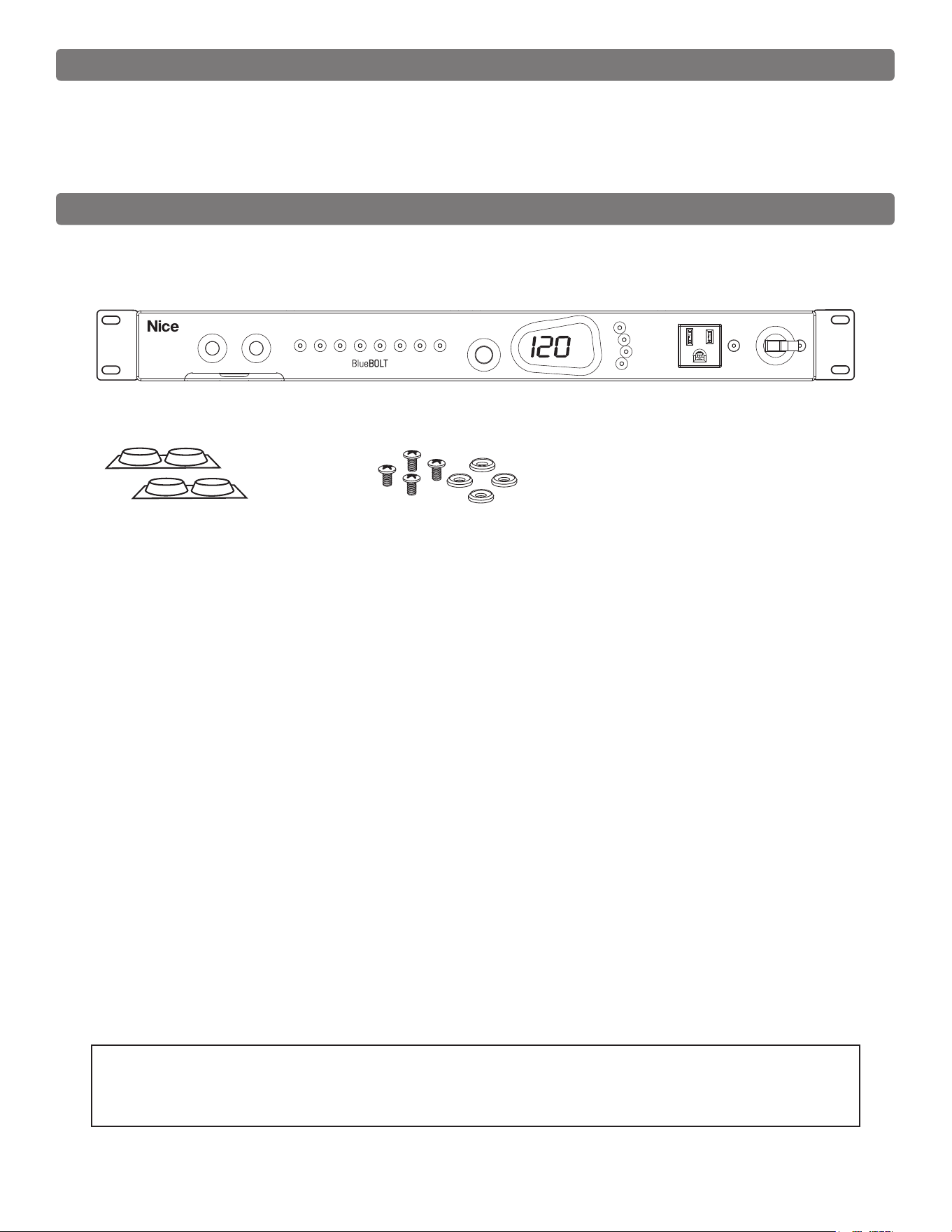
Front Panel Features Overview
1. Read these instructions.
2. Keep these instructions.
3. Heed all warnings.
4. Follow all instructions.
5. WARNING: Do not use this apparatus near water. To reduce the risk of re or
electric shock, do not expose this apparatus to rain or moisture.
6. CAUTION - Contains Always On Receptacles. To reduce risk of shock -
Disconnect M4320-PRO from power source before servicing any equipment
connected to M4320-PRO.
7. Clean only with dry cloth.
8. Do not install near any heat sources such as radiators, heat registers, stoves,
or other apparatuses that produce heat.
9. Do not defeat the safety purpose of the polarized or grounding type plug. A
polarized plug has two blades, with one wider than the other. A grounding type
plug has two blades and a third grounding prong. The wide blade or the third
prong is provided for your safety. If the provided plug does not t into your
outlet, consult an electrician for replacement of the obsolete outlet.
10. Protect the power cord from being walked on or pinched, particularly at plugs,
convenience receptacles, and the point where they exit from the apparatus.
11. Only use attachments/accessories specied by the manufacturer.
12. Refer all servicing to qualied service personnel. Servicing is required when
the apparatus has been damaged in any way, such as power-supply cord
or plug is damaged, liquid has been spilled or objects have fallen into the
apparatus, the apparatus has been exposed to rain or moisture, does not
operate normally, or has been dropped.
13. Where the power cord is used as the main disconnect device, the disconnect
device shall remain readily accessible.
14. This device must be connected to a main socket outlet with a protective
earthing connection.
PULL OUT CARD:
Quick reference for default prole and
device type list. Located under the
reboot buttons.
REBOOT 1 & 2:
Press either button for 2 seconds
to initiate a “reboot” sequence of
outlet 1 or 2 (default). Press both
simultaneously for 2 seconds to
initiate a full power-up or shut down
sequence. The front panel outlet is
always on, unless the circuit breaker is
set to OFF.
VOLTS/AMPS/BRIGHTNESS:
Rotate knob for front panel brightness
control, and press to toggle the meter
between VOLTS and AMPS mode.
UNSAFE VOLTAGE:
If the line voltage is less than 100 Vac
or greater than 134 Vac, the outlets
will shut off and this light will ash red.
The meter will show the current prole:
P1-P4 (presets), or PP (personal
prole).
A “personal prole” is a conguration
that has been changed from the
presets by an external control (through
the COMMUNICATIONS CARD)
To change the preset prole, press
REBOOT 1 repeatedly until the
desired prole is displayed. To select
the displayed prole and exit, press
REBOOT 2.
To exit without changing the prole,
press REBOOT 1 until “PE” (prole
exit) is displayed, then press REBOOT
2. Turn breaker to ON when nished.
See the following page for detailed
preset prole information.
Users of the TCP/IP (BlueBOLT-
CV3) card may access an additional
“IP” menu by pressing REBOOT 1,
cycling past PP and P1-P4 until IP is
displayed.
Then pressing REBOOT 2 will display
the unit’s IP address, one octet at a
time.
For example, if the IP address is
192.168.1.50, then the meter will
display 192, followed in 2 seconds by
168, then 1, then 50, and terminated
by ---.
The menu will then automatically
exit and the unit will return to normal
operation.
BREAKER:
Flashes red if the circuit breaker is OFF.
WIRING FAULT:
Illuminates red if the house wiring is
reverse-wired or the ground is not
connected.
TEMPERATURE:
Flashes red if the internal microprocessor
temperature is greater than 60 ºC.
PROFILES:
These are congurations that dictate
outlet sequencing timings and trigger
assignments.
To change the prole, set the circuit
breaker to OFF (the BREAKER light will
ash red) and press REBOOT 1 & 2
simultaneously for 8 seconds.
PLEASE NOTE: The lights’ status is obvious, when the outlet is just plain “ON” or just plain “OFF”. However, there are transition states that cause the lights to
blink. The lights will blink when performing a triggered cycle, but when a server initiated cycle command occurs, it just goes “OFF”, delays, then “ON”.
5
VOLTS
OUTLET STATUS
UNSAFE VO LTAGE
ALWAYS ON
20A
BREAKER
WIRING FAULT
TEMPERATURE
VOLTS/AMPS
BRIGHTNESS
1 2 3 4 5 6 7 8
REBOOT 1 REBOOT 2
M4320-PRO
ENABLED
Preset Prole Information
6
DEFAULT OUTLET SEQUENCING (preset profile P1, by outlet #s):
Start up: 1→(1 sec)→2→(1 sec)→3→(1 sec)→4→(1 sec)→5→(1 sec)→6→(1 sec)→7→(5 sec)→8
Shut down: 8→(5 sec)→7→(5 sec)→6→(1 sec)→5→(1 sec)→4→(1 sec)→3→(1 sec)→2→(1 sec)→1
Reboot 1: 1(off)→(30 sec)→1(on)
Reboot 2: 2(off)→(30 sec)→2(on)
DC TRIGGER ON: 7(on)→(5 sec)→8(on)
DC TRIGGER OFF: 8(off)→(5 sec)→7(off)
With switching on and off
BREAKER or holding both
REBOOT buttons.
A/V + MODEM OUTLET SEQUENCING (profile P2, by outlet #s):
Start up: 1→(15 sec)→2→(1 sec)→3→(1 sec)→4→(1 sec)→5→(1 sec)→6→(1 sec)→7→(5 sec)→8
Shut down: 8→(5 sec)→7→(5 sec)→6→(1 sec)→5→(1 sec)→4→(1 sec)→3→(1 sec)→2→(1 sec)→1
Reboot 1: 1 and 2 (off)→(30 sec)→1 and 2 (on)
Reboot 2: 3(off)→(30 sec)→3(on)
DC TRIGGER ON: 7(on)→(5 sec)→8(on)
DC TRIGGER OFF: 8(off)→(5 sec)→7(off)
With switching on and off
BREAKER or holding both
REBOOT buttons.
A/V + EXTENDED DELAYS OUTLET SEQUENCING (profile P3, by outlet #s):
Start up: 1→(10 sec)→2→(10 sec)→3→(10 sec)→4→(10 sec)→5→(10 sec)→6→(10 sec)→7→(20 sec)→8
Shut down: 8→(20 sec)→7→(20 sec)→6→(10 sec)→5→(10 sec)→4→(10 sec)→3→(10 sec)→2→(10 sec)→1
Reboot 1: 1 and 6 (off)→(45 sec)→1 and 6 (on)
Reboot 2: 3(off)→(45 sec)→3(on)
DC TRIGGER ON: 5(on)→(20 sec)→7(on)→(20 sec)→8 (on)
DC TRIGGER OFF: 8(off)→(20 sec)→7(off)→(30 sec)→5(off)
With switching on and off
BREAKER or holding both
REBOOT buttons.
NETWORK + CONTROL DELAYS OUTLET SEQUENCING (profile P4, by outlet #s):
Start up: 1→(15 sec)→2→(15 sec)→3→(5 sec)→4→(5 sec)→5→(5 sec)→6→(5 sec)→7→(10 sec)→8
Shut down: 8→(10 sec)→7→(10 sec)→6→(5 sec)→5→(5 sec)→4→(5 sec)→3 (outlets 1 & 2 are always on)
Reboot 1: 1(off)→(30 sec)→1(on)
Reboot 2: 2 and 3(off)→(30 sec)→2 and 3(on)
DC TRIGGER ON: 7(on)→(10 sec)→8(on)
DC TRIGGER OFF: 8(off)→(10 sec)→7(off)
With switching on and off
BREAKER or holding both
REBOOT buttons.
PROFILE 1 (P1)
PROFILE 2 (P2)
PROFILE 3 (P3)
PROFILE 4 (P4)
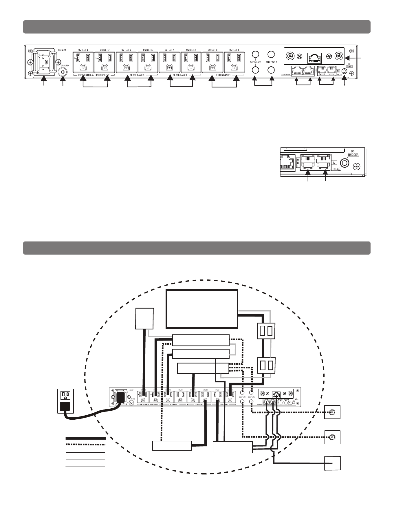
The Bubble of Protection
Sample setup to indicate the basic conguration for a “Bubble of Protection”.
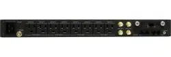
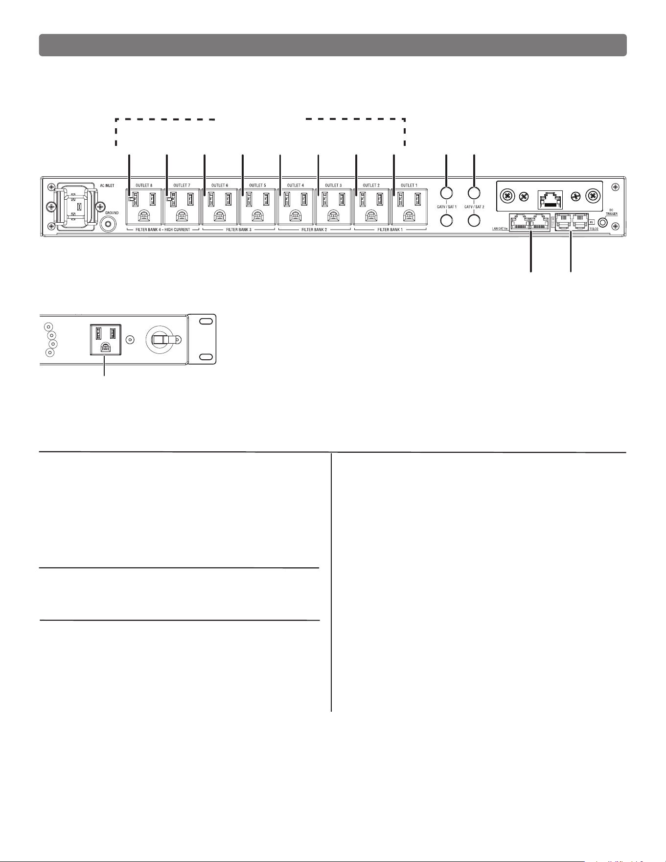
Rear Panel Features Overview
1 2 4 5
8
76
OUT IN
BANK 4 BANK 3 BANK 2 BANK 1
BlueBOLT-CV3
M4320-PRO
TV
B
U
B
B
L
E
O
F
P
R
O
T
E
C
T
I
O
N
NETWORK SWITCH
SAT
SAT
CAT 5e
DVD / BLU-RAY
A / V RECEIVER
MEDIA SERVER / EXTENDER
DVR
SUB
MIW-XT OUTLET
MIW-XT INLET
AC
COAX
CAT 5e
SIGNAL
SPEAKER
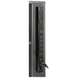
Outlets 8 and 7 - 20A
1. Power inlet:
M4320-PRO (120 Vac/20 A, IEC 320 C20 do not remove steel retention clip.
(20A plug)
2. Ground lug:
Connect to Nice MOD-series signal protection module grounding busses with
14 AWG (<12” length) wire to expand signal protection capabilities.
3. Outlets:
All rear panel outlets are separately controlled. They are grouped into four (4)
lter-isolated banks.
BANKS 1-3: Filtered Outlets (Outlets 1, 2, 3, 4, 5, 6)
76dB (5 kHz – 250 kHz), 46dB (250 kHz - 1 MHz)
BANK 4: High-Current Outlets (Outlets 7-8, 20A)
60dB (5 kHz – 450 kHz), 46dB (450 kHz - 1 MHz)
4. CATV/SAT 1 & 2:
Universal voltage (±75V clamping), <0.5 dB @ 0 Hz - 2.2 GHz.
5. LAN Cat 5e
10/100/1000BASE-T compatible): RJ-45 (8P8C) Ethernet protection pass-through.
6. Telco:
RJ-11 (6P2C) analog telephone/
DSL protection pass- through. Do not
connect in reverse OUT - Connects to
Equipment IN - Comes in from the
wall
7. DC Trigger Input:
3.5mm mono jack, ± (5-24 VDC) tip ring.
8. TCP/IP card (BlueBOLT) installed
7
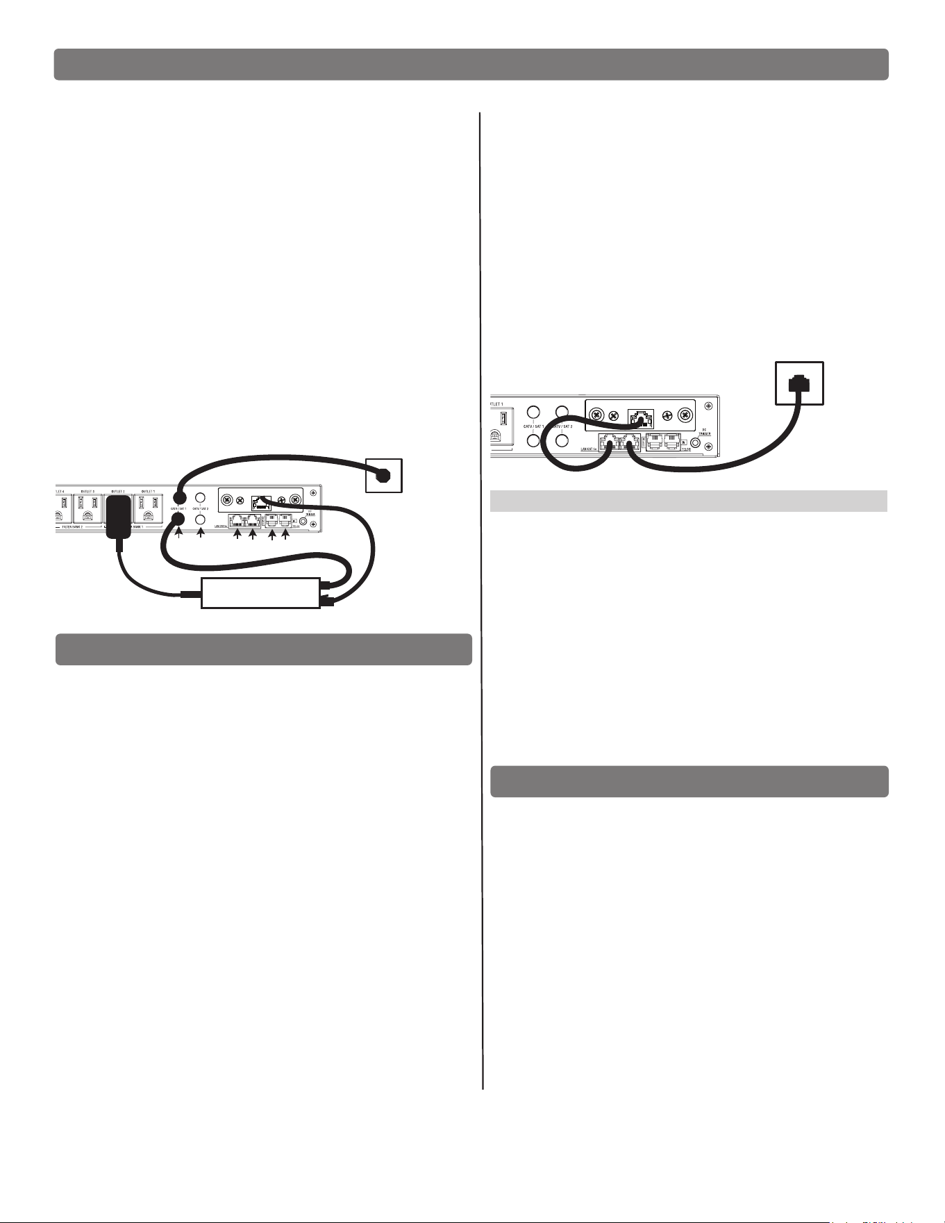
Getting Setup for BlueBOLT
NOTE: You will need the BlueBOLT-CV3’s unique MAC ADDRESS and
CHALLENGE KEY (duplicate labels provided in packaging on cover of Quick
Start Guide as well as on the card itself) in order to register the BlueBOLT
device online.
SYSTEM SETUP #1
Network Equipment Powered by M4320-PRO
(devices in same room)
Step 1: Connect the power supply for the modem/router into the
M4320-PRO.
Step 2:
Connect the coaxial line or telephone DSL line from the wall, to
M4320- PRO signal line pass-through protection circuits.
Step 3: Route coaxial cable line or telephone DSL line from the M4320-
PRO back to modem/router’s input.
Step 4: Plug in and switch on M4320-PRO.
BlueBOLT Online Registration
NOTE: Make sure to complete system setup #1 or # 2 before registering.
Step 1. Log into www.mybluebolt.com for online registration.
Your BlueBOLT enabled M4320-PRO Power Management Component is
completely plug-and-play and does not require any software installation or
network conguration (including conguring of network ports). The online
BlueBOLT control interface is operated through your web browser.
Step 2. Using any Internet connected computer, go to www.mybluebolt.
com in your standard Internet browser. Please make sure your browser is
up to date with the latest software for best BlueBOLT interface performance.
Step 3. Follow the on screen instructions to create an account and/or take
control of your BlueBOLT enabled product.
Once you input the MAC ADDRESS and included CHALLENGE KEY, follow
the on-screen troubleshooting guide. If BlueBOLT cannot detect your device,
conrm you’re allowing up to 60 seconds. Conrm an Internet connection by
accessing a general website Niceforyou.com.
SYSTEM SETUP #2
Network Equipment NOT-Powered by M4320-PRO
(devices in separate rooms)
Step 1. Connect network Ethernet cable from PoE/network adapter
or wall plate to the Ethernet pass-through protection port on
M4320-PRO.
Step 2. Connect second Ethernet cable from pass-through protection
port to BlueBOLT-CV3 card.
Step 3. Power on M4320-PRO. (NOTE: adding a device to your
home/ofce network may require a power cycle of the router/
modem to establish connection.
Advanced Operation
Besides providing access to Nice’s hosted BlueBOLT platform, the included
BlueBOLT-CV3 card also supports the following networking protocols:
*UDP (port 57010), for advanced interfacing to control and automation
systems within the local network. Messages are in XML format and
are detailed in the BLUEBOLT-CV3 user manual, available online at
Niceforyou.com.
*Telnet (default port 23), for interfacing….*HTTP (web server at default
port 80) for outlet control, outlet settings and networking conguration on
the local area network.
For more information, see the application note BlueBOLT Advanced
Networking, available online at www.mybluebolt.com.
Troubleshooting
• Is your Power Management Component receiving power? Check the
power cable and conrm the unit’s breaker is in the ON position.
• Is your BlueBOLT-CV3 card installed properly? The “Link” light should
be illuminated (solid green) and the “Activity” light should be blinking
intermittently (green).
• Is your Internet connection functioning? Can you access a general
web page?
• Is your BlueBOLT-CV3 card connected to your internet router or
modem? Check the Ethernet cable and conrm that the unit is
connected to an active Internet connection, and make sure those
connected devices are receiving power.
• If you have answered “Yes” to all of these questions and are still
unable to connect your M4320-PRO component, please contact Nice
customer service at 760-438-7000.
8
BlueBOLT-CV3
AC
ETHERNET
CABLE IN
FROM WALL
AC
AC
MODEM / ROUTER
ETHERNET
CABLE
BlueBOLT
COAX CABLE
COAX LAN TEL
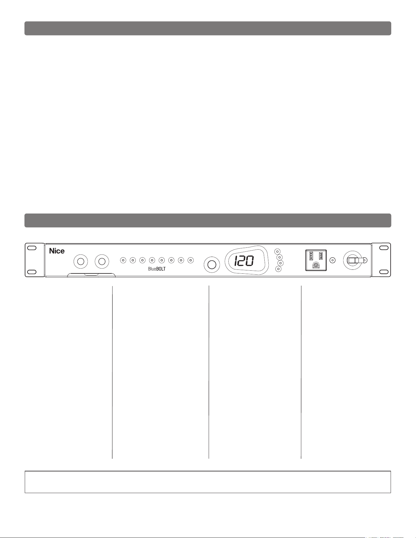
Identify Connected Equipment
Use this diagram to write in what pieces of equipment are plugged into each outlet for an easy reference. Please note that the outlets start at No. 8 on the
left. The outlet indicator lights on the front panel are numbered 1 through 8 left to right.
VOLTS
OUTLET STATUS
UNSAFE VO LTAGE
ALWAYS ON
20A
BREAKER
WIRING FAULT
TEMPERATURE
VOLTS/AMPS
BRIGHTNESS
1 2 3 4 5 6 7 8
REBOOT 1 REBOOT 2
M4320-PRO
ENABLED
8 7 6 5 4 3 2
2
1
1
Outlets
CATV/SAT
LAN TEL
FRONT PANEL OUTLET
Additional Notes:
__________________________________________
__________________________________________
__________________________________________
__________________________________________
__________________________________________
__________________________________________
__________________________________________
__________________________________________
__________________________________________
__________________________________________
__________________________________________
__________________________________________
MAC ADDRESS __ __-__ __-__ __-__ __ -__ __-__ __
CHALLENGE KEY __ __ __ __-__ __ __ __-__ __ __ __
Name / Location of Installation
___________________________________________
___________________________________________
___________________________________________
Phone Number(s)
___________________________________________
___________________________________________
9

Telnet/ Protocol Specication
Command Set/Status Messaging
The following commands are applicable when communicating with your M4320-PRO via direct connection.
OVERVIEW
The purpose of this document is to outline the command set used to
communicate with and control the M4320-PRO.The data communication
feature will most often be used to interface with automation systems.
It may also be used to control and congure the unit manually using a
standard terminal emulation program (i.e. Windows Hyper-Terminal)
1. MESSAGE CONSTRUCTS
All messages are in the form of ASCII character strings that start with a
symbol (!,?,$) to indicate the type of message and are terminated with a
carriage return <CR> ASCII character 0Dh (hex), 13d (decimal).
1.0 The M4320-PRO unit will discard the incoming message under the following
conditions:
1.0.1 Invalid start character or parameter
1.0.2 If a message overruns the receiver buffer (32 characters) it will
be truncated.
1.1 There are three data types transmitted between the M4320-PRO and the
controller hardware:
1.1.1 COMMAND: A message sent to the M4320-PRO unit from the
controller requesting a specic action by the M4320-PRO unit.
Command strings start with an exclamation point (!, 21h, 33d).
Some commands require a parameter to be included in the
message. The parameter must be separated from the command
with a space character (<SP>, 20h, 32d). In the command
descriptions, parameters will be described in bold italic font.
1.2.1 QUERY: A message sent to the M4320-PRO unit from the
controller requesting a status message to be returned.
Query strings start with a question mark (?, 3Fh, 63d).
1.2.2 RESPONSE: A message sent from the M4320-PRO unit to
the controller indicating the current status. Response
strings start with a dollar sign ($, 24h, 36d).
1.2.3 The command prompt (>) is displayed when ready for next
command/query.
POWER CYCLE COMMAND USING TELNET PROTOCOL WITH BlueBOLT-CV3
#CYCLE Turns an outlet off, then delays before turning it back on.
(NOTE - THIS COMMAND IS ONLY AVAILABLE WHEN USING THE TELNET PROTOCOL WITH THE
BlueBOLT-CV3 INTERFACE. IT IS NOT SUPPORTED OVER SERIAL (RS-232) CONNECTION).
Command: #CYCLE outlet:delay<CR>
outlet = {1..8}
delay = {1..65535} seconds
Example: #CYCLE 2:28 This turns outlet 2 off for 28 seconds,
then back on.
Action: Turns off outlet then waits for delay seconds and nally turns
outlet back on.
Response: There are no direct responses from this command, but the outlet
status change messages will be sent as the outlet changes state:
$OUTLETn = status
Where n = {1..8}
Status = {ON, OFF}
10

Telnet Command Set / Protocol Specications (continued)
3. CONTROLLER COMMANDS
The following are commands sent by the controlling equipment to the
M4320-PRO unit.
NOTE: Responses are only transmitted if unsolicited feedback (§3.9) is
enabled.
3.0 GREEN BUTTON
3.0.1 Command: !GREEN_BUTTON<CR>
3.0.2 Action: Power down or up, all outlets controlled by this trigger. Has the
same effect as if someone pressed both REBOOT Button #1 and
#2 at the same time for 2 seconds.
3.0.3 Response: If turning off outlets: $ENTERING GREEN MODE<CR>
If turning on outlets $LEAVING GREEN MODE<CR>
3.1 REBOOT 1
3.1.1 Command: !REBOOT_1<CR>
3.1.2 Action: Power cycle the outlets controlled by this trigger
Has the same effect as if someone pressed the
reboot button #1for 2 seconds.
Default is outlet 1
3.1.3 Response: $BUTTON_1 = TRIGGERED<CR>
3.2 REBOOT 2
3.2.1 Command: !REBOOT_2<CR>
3.2.2 Action: Power cycle the outlets controlled by this trigger
Has the same effect as if someone pressed the
reboot button #2
Default is outlet 2
3.2.3 Response: $ BUTTON_2 = TRIGGERED <CR>
3.3 ALL OFF
Turns off all outlets including those designated as always on. Turn off is immediate with no
delay.
3.3.1 Command: !ALL_OFF<CR>
3.3.2 Action: All outlet relays turn OFF. Terminates any running turn on or
turn off sequence. Overrides the DC trigger input.
3.3.3 Response: $PWR = OFF<CR>
3.4 ALL ON
Turns on all outlets. Turn on is immediate with no delay.
3.4.1 Command: !ALL_ON<CR>
3.4.2 Action: All outlet relays turn ON. Terminates any running turn on or
turn off sequence. Overrides the DC trigger input.
3.4.3 Response: If successful: $PWR = ON<CR>
If over-voltage fault: $PWR=OVERVOLTAGE<CR>
If under-voltage fault: $PWR =UNDERVOLTAGE<CR>
3.5 SWITCH OUTLET
Turns a specic outlet on or off. Switching is immediate with no delay.
3.5.1 Command: !SWITCH outlet state<CR>
outlet = {1..8}
state = {ON, OFF}
Example: !SWITCH 2 ON<CR> (turns on outlet 2)
3.5.2 Action: Immediately switches outlet to state.
3.5.3 Response: If outlet or state are invalid,
$INVALID_PARAMETER<CR>
If outlet and state are valid, and no fault exists, a
conrmation message is sent. Refer to §5.1.2.
If over-voltage fault: $PWR = OVERVOLTAGE<CR>
If under-voltage fault:
$PWR = UNDERVOLTAGE<CR>
If no fault $OUTLET1 = ON<CR>
3.6 SET TRIGGER
Assigns the trigger(s) for an outlet.
3.6.1 Command: !SET_TRIGGER outlet triggersource<CR>
outlet = { 1..8 }
triggersource = { NONE, BUTTON_1, BUTTON_2,
BUTTON_GREEN, TRIGIN} where:
NONE = Outlet is always ON
BUTTON_n = Trigger on front panel
button n where n is {1,2}.
BUTTON_GREEN = Both buttons 1 & 2 being
pressed.
TRIGIN = Trigger on DC input trigger.
Example: !SET_TRIGGER 3 TRIGIN<CR> (sets outlet 3
to be controlled by the DC trigger input).
3.6.2 Action: Sets the trigger for outlet to triggersource.
Trigger commands are additive,
Eg. !SET_TRIGGER 3 TRIGIN<CR>
!SET_TRIGGER 3 BUTTON_GREEN<CR>
Sets DC trigger and green button for outlet 3.
To clear triggers the NONE command must be used
.
3.6.3 Response: If outlet and triggersource are valid:
$TRIGGER FOR outlet = triggersource<CR>
If outlet or triggersource are invalid, $INVALID_
PARAMETER<CR>
11

Rs-232 and Telnet Command Set / Protocol Specications (continued)
3.11 RESET FACTORY SETTINGS
Resets all of the custom conguration settings (i.e. triggers, delays, feedback mode,
& linefeed mode) to their original factory settings listed below.
3.11.1 Command: !RESET_ALL<CR>
3.11.2 Action: Resets the conguration below:
TRIGGER FOR 1 = BUTTON_1, GREEN_BUTTON
TRIGGER FOR 2 = BUTTON_2, GREEN_BUTTON
TRIGGER FOR 3 = GREEN_BUTTON
TRIGGER FOR 4 = GREEN_BUTTON
TRIGGER FOR 5 = GREEN_BUTTON
TRIGGER FOR 6 = GREEN_BUTTON
TRIGGER FOR 7 = DC_TRIGGER, GREEN_BUTTON
TRIGGER FOR 8 = DC_TRIGGER, GREEN_BUTTON
DELAY FOR 1 = 1,16
DELAY FOR 2 = 2,15
DELAY FOR 3 = 3,14
DELAY FOR 4 = 4,13
DELAY FOR 5 = 5,12
DELAY FOR 6 = 6,11
DELAY FOR 7 = 7,6
DELAY FOR 8 = 12,1
REBOOT1 DELAY = 30
REBOOT2 DELAY = 30
FEEDBACK = ON
LINEFEED = ON
PROFILE = 1
3.11.3 Response: $FACTORY SETTINGS RESTORED<CR>
3.12 SET PROFILE
Sets all of the custom conguration settings (i.e. triggers, delays, feedback mode,
& linefeed mode) to the prole selected. The settings are listed below.
3.12.1 Command: !SET_PROFILE n<CR>
Where n is 1,2,3,4
3.12.2 Action: P1 conguration is the same as !RESET_ALL
3.12.3 Action: P2 conguration below:
TRIGGER FOR 1 = BUTTON_1, GREEN_BUTTON
TRIGGER FOR 2 = BUTTON_1, GREEN_BUTTON
TRIGGER FOR 3 = BUTTON_2, GREEN_BUTTON
TRIGGER FOR 4 = GREEN_BUTTON
TRIGGER FOR 5 = GREEN_BUTTON
TRIGGER FOR 6 = GREEN_BUTTON
TRIGGER FOR 7 = DC_TRIGGER, GREEN_BUTTON
TRIGGER FOR 8 = DC_TRIGGER, GREEN_BUTTON
DELAY FOR 1 = 1,16
DELAY FOR 2 = 16,15
DELAY FOR 3 = 17,14
DELAY FOR 4 = 18,13
DELAY FOR 5 = 19,12
DELAY FOR 6 = 20,11
DELAY FOR 7 = 21,6
DELAY FOR 8 = 26,1
REBOOT1 DELAY = 30
REBOOT2 DELAY = 30
FEEDBACK = ON
LINEFEED = ON
PROFILE = 2
3.7 SET REBOOT DELAY
Assign the delay between the last outlet turning off and the beginning of the turn on se-
quence in a reboot cycle.
3.7.1 Command: !SET_REBOOT_DELAY button_1 button_2<CR>
Example: !SET_REBOOT_DELAY 30 5<CR>
(sets the reboot delay for Button_1 to 30 seconds and the delay for
button_2 to 5 seconds.)
3.7.2 Response: If button_1 button_2 are valid:
$BUTTON_1 DELAY = button_1<CR>
$BUTTON_2 DELAY = button_2<CR>
If button_1or button_2 are not valid:
$INVALID_PARAMETER<CR>
Where button_1 = { 1-255 } (seconds)
button_2 = { 1-255 } (seconds)
3.8 SET DELAY
Assigns the turn on and turn off delays for an outlet OUTLET or DC trigger output.
3.8.1 Command: !SET_DELAY outlet ondelay offdelay<CR>
outlet = { 1..8 }
ondelay = { 0-255 } (seconds)
offdelay = { 0-255 } (seconds)
Example: !SET_DELAY 4 5 1<CR>
(sets outlet 4 turn-on delay to 5 sec. and turn-off delay to 1 sec.)
3.8.2 Action: Sets the turn on delay for outlet to ondelay
Sets the turn off delay for outlet to offdelay
3.8.3 Response: If outlet, ondelay and offdelay are valid:
$DELAY FOR outlet = ondelay offdelay<CR>
If outlet, ondelay or offdelay are invalid:
$INVALID_PARAMETER<CR>
3.9 SET FEEDBACK MODE
Sets the feedback to ON (unsolicited) or OFF (polled). When ON, a message will be sent to
the controller every time the status of an input (i.e. trigger), output (i.e. outlet) or power state
(i.e. overvoltage) changes. If feedback is OFF, the controller must poll for state changes.
3.9.1 Command: !SET_FEEDBACK mode<CR>
mode = { ON, OFF }
3.9.2 Action: Sets the feedback mode to mode.
3.9.3 Response: If mode = ON, $FEEDBACK = ON<CR>
If mode = OFF, $FEEDBACK = OFF<CR>
If mode is invalid, $INVALID_PARAMETER<CR>
3.10 SET LINEFEED MODE
Controls the linefeeds (ASCII: 10d, 0Ah) sent with each response. When ON, each response
will end with a linefeed. When OFF, all responses will not end with a linefeed.
3.10.1 Command: !SET_LINEFEED mode<CR>
mode = { ON, OFF }
3.10.2 Action: Sets the linfeed mode to mode.
3.10.3 Response: If mode = ON, $LINEFEED = ON<CR>
If mode = OFF, $LINEFEED = OFF<CR>
If mode is invalid, $INVALID_PARAMETER<CR>
12

3.12.4 Action: P3 conguration below:
TRIGGER FOR 1 = BUTTON_1, GREEN_BUTTON
TRIGGER FOR 2 = GREEN_BUTTON
TRIGGER FOR 3 = BUTTON_2, GREEN_BUTTON
TRIGGER FOR 4 = GREEN_BUTTON
TRIGGER FOR 5 = DC_TRIGGER , GREEN_BUTTON
TRIGGER FOR 6 = BUTTON_1, GREEN_BUTTON
TRIGGER FOR 7 = DC_TRIGGER, GREEN_BUTTON
TRIGGER FOR 8 = DC_TRIGGER, GREEN_BUTTON
DELAY FOR 1 = 1,90
DELAY FOR 2 = 10,80
DELAY FOR 3 = 20,70
DELAY FOR 4 = 30,60
DELAY FOR 5 = 40,50
DELAY FOR 6 = 50,40
DELAY FOR 7 = 60,20
DELAY FOR 8 = 80,1
REBOOT1 DELAY = 45
REBOOT2 DELAY = 45
FEEDBACK = ON
LINEFEED = ON
PROFILE = 3
3.12.5 Action: P4 conguration below:
TRIGGER FOR 1 = BUTTON_1
TRIGGER FOR 2 = BUTTON_2
TRIGGER FOR 3 = BUTTON_2, GREEN_BUTTON
TRIGGER FOR 4 = GREEN_BUTTON
TRIGGER FOR 5 = GREEN_BUTTON
TRIGGER FOR 6 = BUTTON_1, GREEN_BUTTON
TRIGGER FOR 7 = DC_TRIGGER
TRIGGER FOR 8 = DC_TRIGGER
DELAY FOR 1 = 1, O
DELAY FOR 2 = 16, O
DELAY FOR 3 = 31, 36
DELAY FOR 4 = 36, 31
DELAY FOR 5 = 41, 26
DELAY FOR 6 = 46, 21
DELAY FOR 7 = 51, 11
DELAY FOR 8 = 61, 1
REBOOT1 DELAY = 30
REBOOT2 DELAY = 30
FEEDBACK = ON
LINEFEED = ON
PROFILE = 4
3.12.3 Response: $PROFILE n SELECTED<CR>
4. QUERIES
4.0 IDENTIFY
Request that the unit identify itself.
4.0.1 Query: ?ID<CR>
4.0.2 Response: $PANAMAX<CR>
$M4320-PRO<CR>
$FIRMWARE: revision<CR>
4.1 FAULT STATUS
Request the on/off status of the outlets and output trigger.
4.1.1 Query: ?FAULTSTAT<CR>
4.1.2 Response: $PWR = status<CR>
$BREAKER = status<CR>
$WIRE FAULT = status<CR>
$TEMPERATURE = status<CR>
$AVM = status<CR>
status = { FAULT, OK }
4.2 TRIGGER STATUS
Request the on/off status of the input trigger.
4.2.1 Query: ?TRIGSTAT<CR>
4.2.2 Response: For trigger ON:
$TRIGIN = ON<CR>
For trigger OFF:
$TRIGIN = OFF<CR>
4.3 OUTLET STATUS
Request the on/off status of the outlets.
4.3.1 Query: ?OUTLETSTAT<CR>
4.3.2 Response: $OUTLET1 = status<CR>
$OUTLET2 = status<CR>
$OUTLET3 = status<CR>
$OUTLET4 = status<CR>
$OUTLET5 = status<CR>
$OUTLET6 = status<CR>
$OUTLET7 = status<CR>
$OUTLET8 = status<CR>
status = { ON, OFF }
4.4 POWER STATUS
Request the status of the input voltage.
4.4.1 Query: ?POWERSTAT<CR>
4.4.2 Response: if input voltage is
within limits: $PWR = NORMAL<CR>
during overvoltage: $PWR = OVERVOLTAGE<CR>
during undervoltage: $PWR = UNDERVOLTAGE<CR>
during recovery: $PWR = RECOVERY<CR>
RS-232 and Telnet Command Set / Protocol Specications (Continued)
PLEASE NOTE:
Zero in the First Position
before the comma (0,)
equates to ALWAYS OFF.
Zero in the Second Position
after the comma (,0)
equates to ALWAYS ON.
13

RS-232 and Telnet Command Set / Protocol Specications (Continued)
5. Responses and Warning Messages
If unsolicited feedback is enabled, the following warning messages will be transmitted
under the conditions outlined in their description.
5.1 OUTLET STATUS CHANGE
5.1.1 Condition: Outlet or trigger output changes (on/off) state.
5.1.2 Message: $OUTLETn = status<CR>
n = { 1..8 }
status = { ON, OFF }
5.2 TRIGGER STATUS CHANGE
5.2.1 Condition: When either front panel button or input trigger status changes, a
status message is sent to the controller.
5.2.2 Message: For BUTTON_1 press: $BUTTON_1 = TRIGGERED<CR>
For BUTTON_2 press: $BUTTON_2 = TRIGGERED<CR>
If input trigger is switched ON: $TRIGIN = ON<CR>
If trigger input is switched OFF: $TRIGIN = OFF<CR>
If Green mode is switched ON: $GREEN MODE = ON<CR>
If Green mode is switched OFF: $GREEN MODE = OFF<CR>
5.3 OVERVOLTAGE
5.3.1 Condition: Input voltage rises above the overvoltage threshold.
5.3.2 Message: $PWR = OVERVOLTAGE<CR>
5.4 UNDERVOLTAGE
5.4.1 Condition: Input voltage falls below the undervoltage threshold.
5.4.2 Message: $PWR = UNDERVOLTAGE<CR>
5.5 RECOVERY
5.5.1 Condition: Input voltage falls within safe operating range following an over-
voltage or under-voltage condition.
5.5.2 Message: $PWR = RECOVERY<CR>
5.6 NORMAL
5.6.1 Condition: Upon leaving the recovery mode following an over-voltage or
under-voltage condition.
5.6.2 Message: $PWR = NORMAL<CR>
5.7 FAULT STATUS
5.7.1 Condition: When the breaker changes status, a message will be sent
indicating the status of the indicator.
5.7.2 Message: $BREAKER = status<CR>
5.7.3 Condition: When a wire fault is detected a message will be sent to indicate
the status of the indicator.
5.7.4 Message: $WIRE FAULT = status<CR>
5.7.5 Condition: When the temperature exceeds the upper safe operating limit, a
message will be sent.
5.7.6 Message: $TEMPERATURE = status<CR>
status = { FAULT, OK }
4.5 VOLTAGE
Request line voltage.
4.5.1 Query: ?VOLTAGE<CR>
4.5.2 Response: $VOLTAGE = xxx<CR>
where xxx is the input line voltage expressed in decimal
format.
$VOLTAGE = 92<CR>
4.6 CURRENT
Request the input current draw.
4.6.1 Query: ?CURRENT<CR>
4.6.2 Response: $CURRENT = xxx<CR>
where xxx is the input current expressed in decimal format.
For example, a current of 3.3A would be expressed as:
$CURRENT = 33<CR>
4.7 HELP
Request a list of all commands and queries.
4.7.1 Query: ?HELP<CR>
4.7.2 Response: Transmit a listing of all commands and queries.
4.8 LIST CONFIGURATION
Request a list of all congurable parameters and current settings.
4.8.1 Query: ?LIST_CONFIG<CR>
4.8.2 Response: $TRIGGER FOR 1 = triggersource<CR>
$TRIGGER FOR 2 = triggersource<CR>
$TRIGGER FOR 3 = triggersource<CR>
$TRIGGER FOR 4 = triggersource<CR>
$TRIGGER FOR 5 = triggersource<CR>
$TRIGGER FOR 6 = triggersource<CR>
$TRIGGER FOR 7 = triggersource<CR>
$TRIGGER FOR 8 = triggersource<CR>
$DELAY FOR 1 = ondelay, offdelay<CR>
$DELAY FOR 2 = ondelay, offdelay<CR>
$DELAY FOR 3 = ondelay, offdelay<CR>
$DELAY FOR 4 = ondelay, offdelay<CR>
$DELAY FOR 5 = ondelay, offdelay<CR>
$DELAY FOR 6 = ondelay, offdelay<CR>
$DELAY FOR 7 = ondelay, offdelay<CR>
$DELAY FOR 8 = ondelay, offdelay<CR>
$FEEDBACK = fb<CR>
$LINEFEED = lf<CR>
$PROFILE = n
$REBOOT_DELAY1 = offdelay
$REBOOT_DELAY2 = offdelay
triggersource = { NONE, BUTTON_1, BUTTON_2, TRIGIN}
ondelay = { 0-255 } (seconds)
offdelay = { 0-255 } (seconds) 0 = Always on
fb = {ON, OFF}
lf = {ON, OFF}
n = {1,2,3,4}
14

M4320-PRO Specications
AC Power
Line Voltage........................................120V, 60Hz
Isolated Banks .............................................4
Voltage Regulation.........................................No
Total Outlets ........................................ 9 Outlets
High Current Outlets .................................. 2 Outlets
Total Current Capacity ....................M4320-PRO 20 A (2400W)
Voltage Protection Rating
(UL 1449 3rd Edition, 3,000A) ..............................330V
Protection Modes..................................L-N, L-G, N-G
Initial Clamping Level........................200V Peak, 141V RMS
Energy Dissipation ..................................2700 Joules
Peak Impulse Current..............................135,000 Amps
Catastrophic Surge Circuit ...................................Yes
Thermal Fusing ...........................................Yes
Auto-resetting Over-voltage shutoff .................134 VAC ± 2 VAC
Auto-resetting Under-voltage shutoff ................100 VAC ± 2 VAC
12v trigger input 5-24 volts DC , 820 ohms Jacks 3.5mm (1/8”) mono
mini-plug.
LAN Protection
Clamping Level .......................................62 ± 6V
Compatibility . . . . . . . . . . . . . . . . . . . . . . . . . . . . . . . 10/100/1000BASE-T
Jacks................................................ RJ-45
Wires Protected .......................................8-Wires
Telco Protection
Fuseless/Auto-resetting .....................................Yes
Clamping Level .........................................260V
Capacitance..................................... 30pf (approx.)
Suppression Modes .........................Metallic & Longitudinal
Connectors ........................................... RJ-11
Lines Protected ...............................2-Wire, Pins 4 & 5
Universal Coax Protection
Bidirectional .............................................Yes
Shielded ................................................Yes
Clamping Level ..........................................75V
Frequency Range................................. 0Hz - 2.2 GHz
Insertion Loss ....................................... < 0.5 dB
Connectors ..............................Female “F”, Gold Plated
Specications subject to change due to product upgrades and improvements.
15

FCC Notice
This equipment has been tested and found to comply with the limits for a Class B Digital Device, pursuant to Part 15 of the FCC Rules. These limits are designed to provide
reasonable protection against harmful interference in residential installation. This equipment generates, uses, and can radiate radio frequency energy and, if not installed
and used in accordance with the instructions, may cause harmful interference to radio communications. However, there is no guarantee that interference will not occur in a
particular installation. If this equipment does cause harmful interference to radio or television reception, which can be determined by turning the equipment off and on, the
user is encouraged to try to correct the interference by one or more of the following measures:
1) Reorient or relocate the receiving antenna.
2) Increase the separation between the equipment and receiver.
3) Connect the equipment into an outlet on a circuit different from that to which the receiver is connected.
4) Consult the dealer or an experienced radio/TV technician for help. Any special accessories needed for compliance must be specied in the instruction.
CAUTION: A shielded-type power cord is required in order to meet FCC emission limits and also to prevent interference to the nearby radio and television reception. It is
essential that only the supplied power cord be used.
CAUTION: Any changes or modications not expressly approved by the guarantee of this device could void the user’s authority to operate the equipment.
Contacting Customer Service
All equipment being returned for repair must have a Return Authorization (RA) number. To get an RA number, please call the Nice Service Department.
Before returning any equipment for repair, please be sure that it is adequately packed and cushioned against damage in shipment, and that it is insured. We suggest that
you save the original packaging and use it to ship the product for servicing. Also, please enclose a note giving your name, address, phone number and a description of the
problem. NOTE: Proof of Purchase is required for warranty consideration.
Nice North America LLC
5919 Sea Otter Place, Suite 100
Carlsbad, CA 92010
DIN-00002 Rev-F
Customer Service:
760-438-7000
Technical Support Hours:
M – F, 5am – 4pm PST
Niceforyou.com
©2024 Nice North America LLC. All rights reserved.