
Switched XPDU
15A Model
User & Installaon Manual
www.xpcc.com | © 2014 Xtreme Power Conversion Corporaon. All rights reserved. (Rev 10/02/14)

Xtreme Power Conversion Corporaon
Switched XPDU User’s Manual
Page 2
Power Distribuon Unit
Table of Contents
Introducon.................................................................................................4
PDU Package................................................................................................4
Funcon.......................................................................................................4
Interface..........................................................................................................................................4
Installaon...................................................................................................5
Rack Mount Instrucons..................................................................................................................5
Diagram...........................................................................................................................................6
Hardware.........................................................................................................................................6
Web Interface..............................................................................................7

Xtreme Power Conversion Corporaon
Switched XPDU User’s Manual
Page 3
Power Distribuon Unit
Introducon
The PDU is an Internet ready device designed and is equipped with an intelligent current- meter (True RMS) that
will indicate the total power consumpon of a power strip.
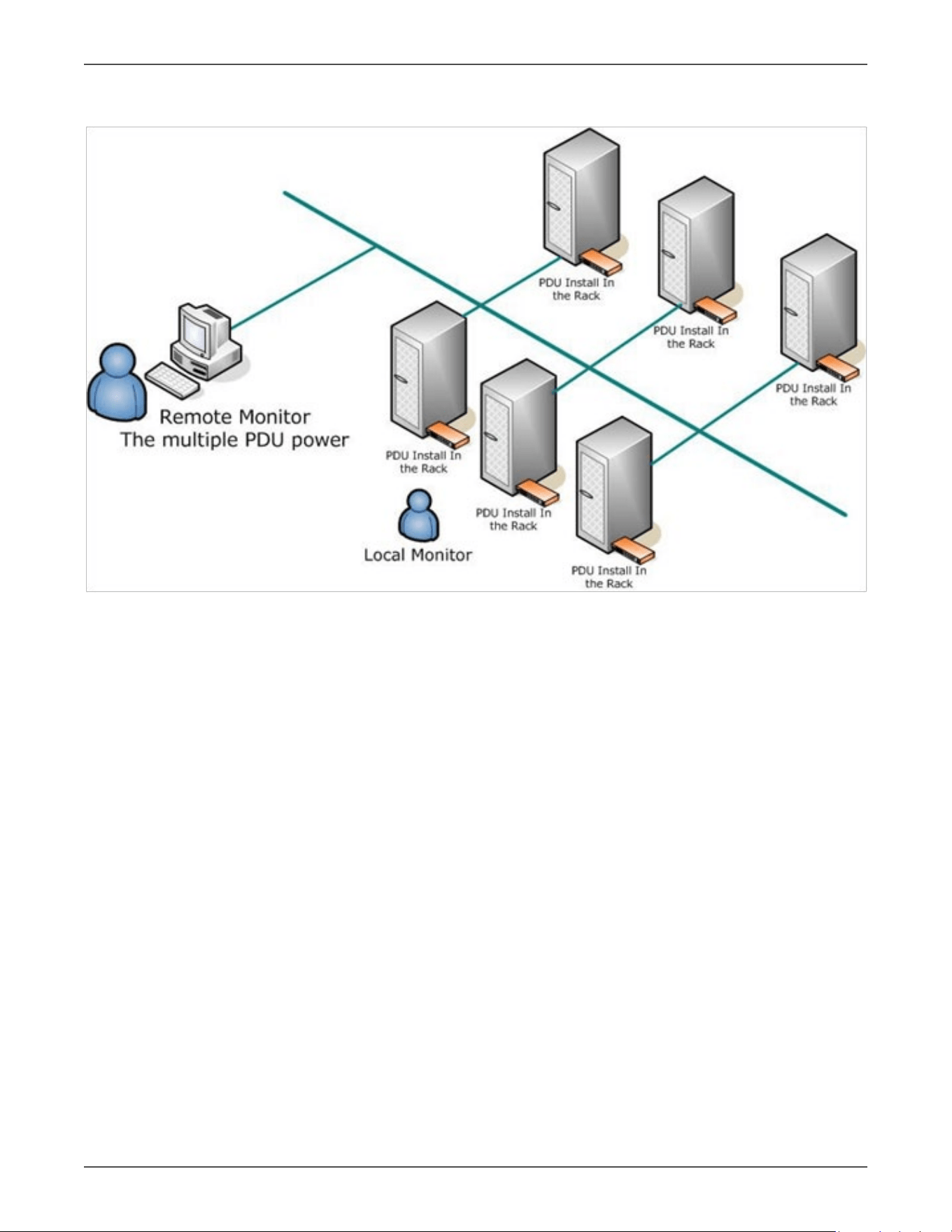
The PDU oers an easy set up and user-friendly communicaon soware. This soware provides the funcon that
assistant manager to remotely monitor the mulple PDU power consumpon to realize the total current power
consumpon and ulizaon for the enterprises.
Features:
• Built-in web server, manager can real me to monitoring the current consumpon of the power strip.
• Build-in true RMS current meter.
• Setup easily, meter can read the IP address directly.
• Homepage support SSL.
• Provide audible alarm when the power consumpon over the threshold of warning and overload.
• Send the email and traps when the power consumpon exceed the trigger value of warning or overload
to the PDU.
• Provide ulity, it can monitor a large mount of PDU at the same me.
• Support the SNMP and provide MIB for the PDU to be monitored by NMS.
• Provide per outlet power protecon by the circuit breaker.
• Real me to control outlets of PDU.
• Indicate outlets status with LED.
• Support power on sequence.
• Opon accessory can support temperature and humidity detecon.
PDU Package
The standard PDU package contains a Power Distribuon Unit with supporng hardware and soware. The com-
ponents of the package are:
• Power Distribuon Unit
• Rack mount Brackets. CD-ROM, it contains:
• User Manual
• PDU Soware
• MIB: Management Informaon Base for Network (PDUMIB.mib)
• Adobe Acrobat Reader
Funcon
Interface

Xtreme Power Conversion Corporaon
Switched XPDU User’s Manual
Page 4
Power Distribuon Unit
Funcons Descripon
Ethernet RJ45 port for network communicaon port.
Audible Alarm
Warning- 1 beep in 1 second.
Overload- 3 beeps in 1 second.
Note: The audible alarm will keep beeping unl the current gets back to normal
and the current is lower than the threshold to 0.5 amps.
Funcon Buon
Press and release to turn o the warning beeping. The overload beeping can
not be cancelled.
Press and hold the key aer 2 beeping; it can let the meter to show up the IP
address
Press and hold the key aer 4 beeping; it can change the way to get IP by DHCP
or xed IP.
Press and hold the key aer 6 beeping; it can reset PDU back to default seng.
Meter 3 digits to display current and IP Address.
ID The idencaon of power bank or PDU.
LED Indicator
SSL (yellow): Light on means web access is protected by SSL.
DHCP (Green): Light on means PDU gets IP address by DHCP.
PDU (Green): Indicate each output power status.
Status (Red): Indicate each circuit status. (by model)
ENV RJ11 for ENV probe aached.
Circuit Breaker Overload power protecon.
Installaon
This secon will provide a quick instrucon to install the PDU.
Rack Mount Instrucons
A. Elevated Operang Ambient - If installed in a closed or mul-unit rack assembly, the operang ambient tem-
perature of the rack environment may be greater than room ambient. Therefore, consideraon should be
given to installing the equipment in an environment compable with the maximum ambient temperature
specied by the manufacturer.
B. Reduced Air Flow - Installaon of the equipment in a rack should be such that the amount of air ow required
for safe operaon of the equipment is not compromised.
C. Mechanical Loading - Mounng of the equipment in the rack should be such that a hazardous condion is not
achieved due to uneven mechanical loading.
D. Circuit Overloading - Consideraon should be given to the connecon of the equipment to the supply circuit
and the eect that overloading of the circuits might have on over current protecon and supply wiring. Ap-
propriate consideraon of equipment nameplate rangs should be used when addressing this concern.
E. Reliable Earthing - Reliable earthing of rack-mounted equipment should be maintained. Parcular aenon
should be given to supply connecons other than direct connecons to the branch circuit (e.g. use of power
strips).”
Xtreme Power Conversion Corporaon
Switched XPDU User’s Manual
Page 5
Power Distribuon Unit
Diagram
Hardware
1. Install mounng brackets.
2. The PDU comes with brackets for mounng in a rack. To mount the PDU into a rack performs the following
procedure:
3. Aach the mounng brackets to the unit, using the four retaining screws provided for each of the brackets.
4. Choose a locaon for the brackets.
5. Align the mounng holes of brackets with the notched hole on the vercal rail and aach with the retain-
ing screws.
6. Connect input and output power.
7. Connect Ethernet cable to the PDU.
8. Switch on the PDU.
Note: The default seng for the way to get IP address is DHCP. If PDU can not get the IP from
DHCP server, the IP address will stay at 192.168.0.216
Note: TO SETUP THE NETWORK SYSTEM FOR PDU, STRONGLY RECOMMEND TO BUILD UP THE POWER MONITOR-
ING NETWORK SYSTEM ISOLATED WITH THE OTHERS, IN ORDER TO KEEP THE STABILITY OF GETTING POWER IN-
FORMATION AND SYSTEM OPERATION.
Xtreme Power Conversion Corporaon
Switched XPDU User’s Manual
Page 6
Power Distribuon Unit
Web Interface
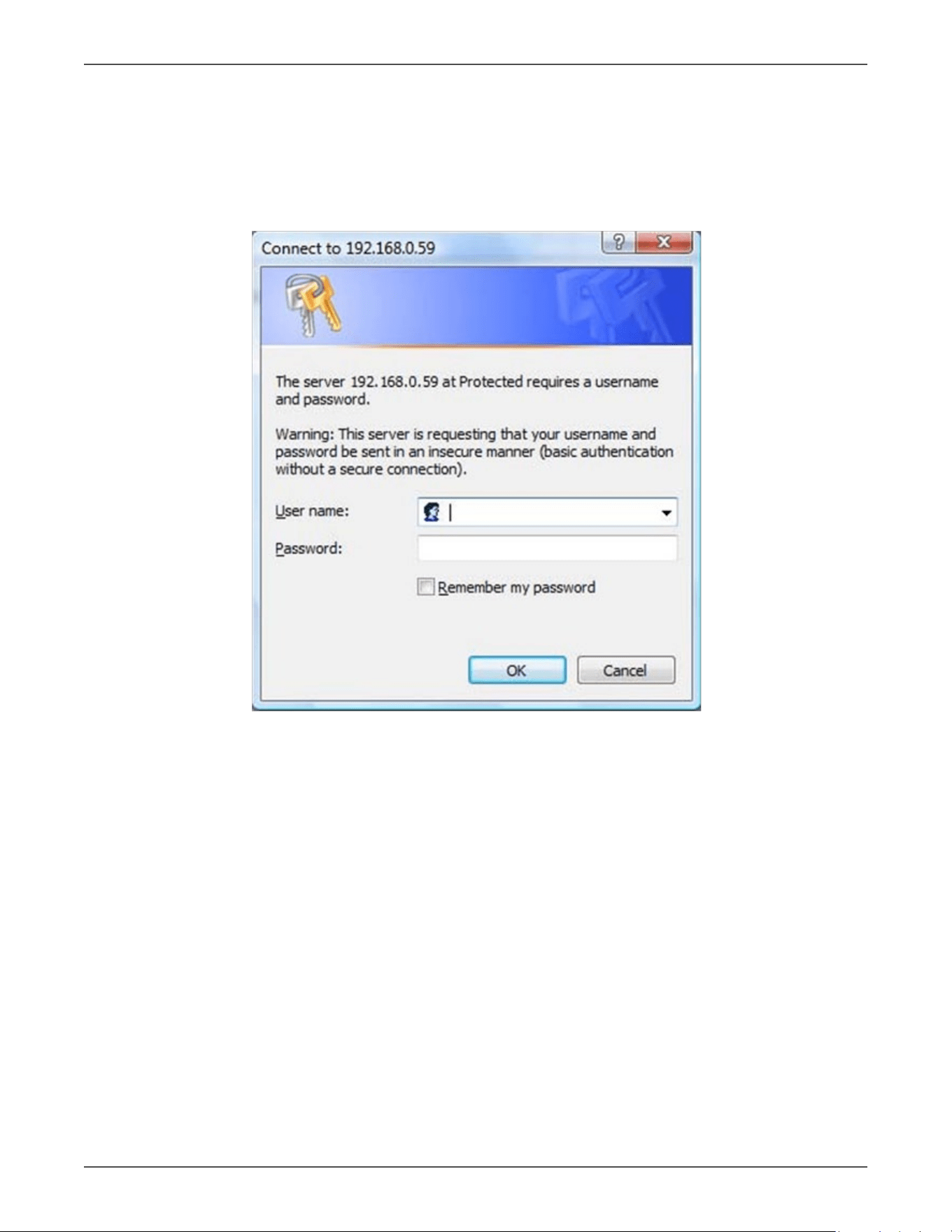
Login:
Input the PDU IP address in the web browser
Default ID is snmp
Password is 1234
Xtreme Power Conversion Corporaon
Switched XPDU User’s Manual
Page 7
Power Distribuon Unit
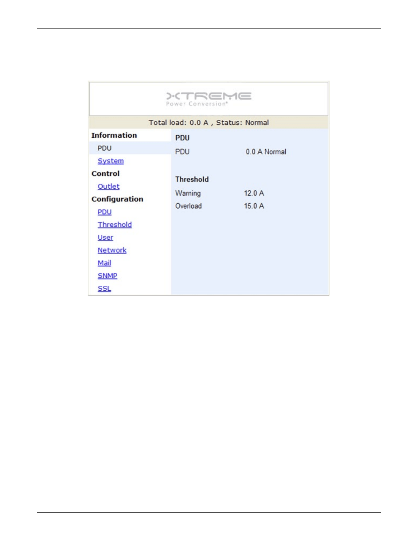
Informaon: PDU
Display total PDU and each outlet power consumpon.
When plug the opon device - ENV probe, it will display temperature and humidity informaon
Xtreme Power Conversion Corporaon
Switched XPDU User’s Manual
Page 8
Power Distribuon Unit
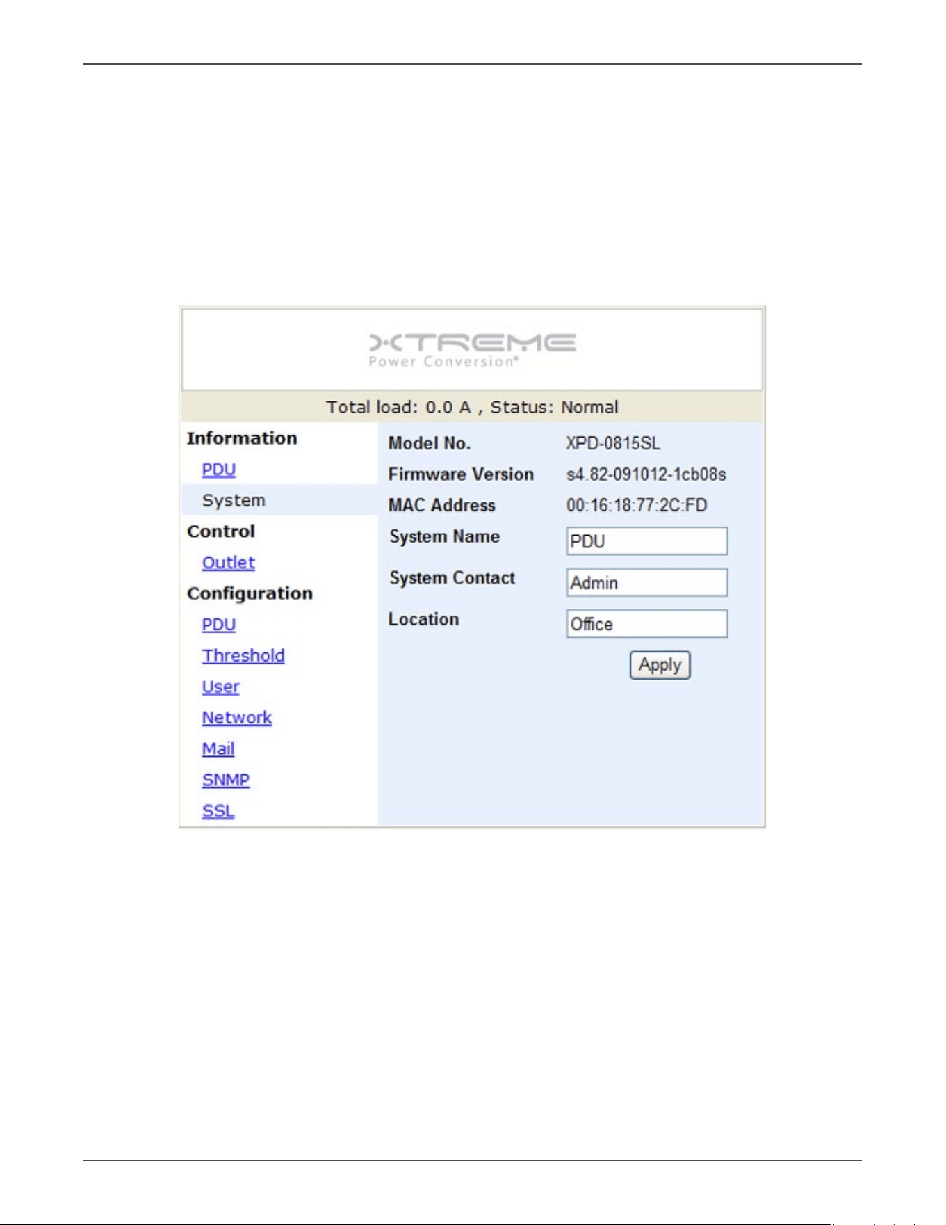
Informaon: System
Indicate PDU system informaon, including:
• Model No.
• Firmware
• Version
• MAC Address
• System Name
• System Contact
• Locaon
Xtreme Power Conversion Corporaon
Switched XPDU User’s Manual
Page 9
Power Distribuon Unit
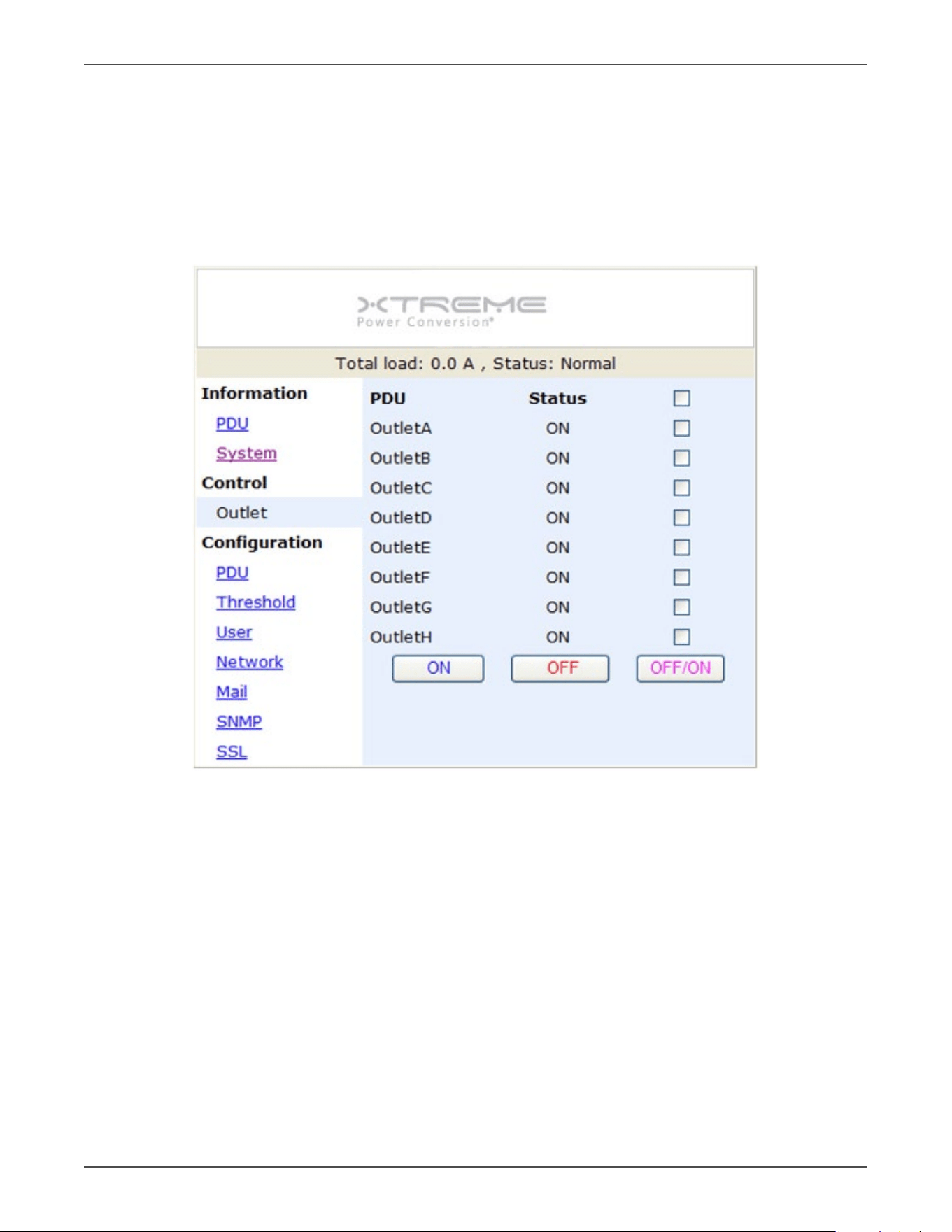
Control: Outlet
Indicate PDU outlet on/o status and control outlet.
Select the outlet by checking the box and then click ON or OFF buon to control output power for PDU
Monitored PDU series does not support this funcon.
ON: Press the icon to turn on the assigned outlets.
OFF: Press the icon to turn o the assigned outlets.
OFF/ON: Press the icon to reboot the assigned outlets.
Xtreme Power Conversion Corporaon
Switched XPDU User’s Manual
Page 10
Power Distribuon Unit
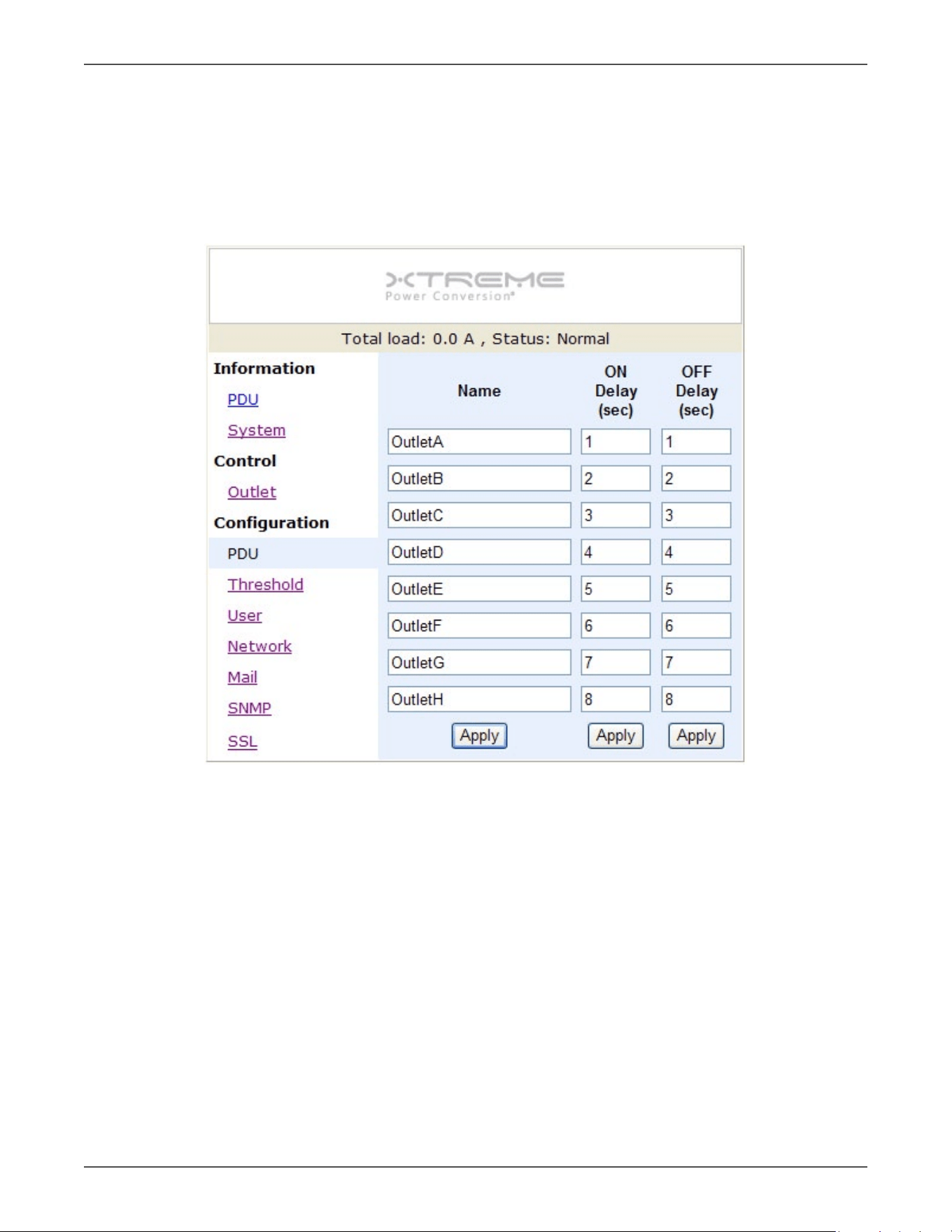
Conguraon: PDU
Set the outlet name and delay me.
Name: Rename the outlet.
ON: Set delay me for power on sequenal.
OFF: Set delay me for power o sequenal.
Note: The maximum delay me is 255 seconds.
Note: Aer PDU is plugged into main power, PDU system will start to sequenally turn on the output socket ac-
cording to the pre-set delay me in PDU web interface. The factory default seng for delay me is one second for
each outlet; therefore the 8 ports PDU will take 8 seconds, 24 ports PDU will take 24 seconds to complete start-up
procedure.
Before the sequence procedure is completed, if a PDU is unplugged from the power source, the outlets which
are not turned on will be regarded as remaining at the power-o status. Next me the PDU is plugged into main
power, these outlets will not be automacally turned on. These outlets can only be turned on by web interface.
Xtreme Power Conversion Corporaon
Switched XPDU User’s Manual
Page 11
Power Distribuon Unit
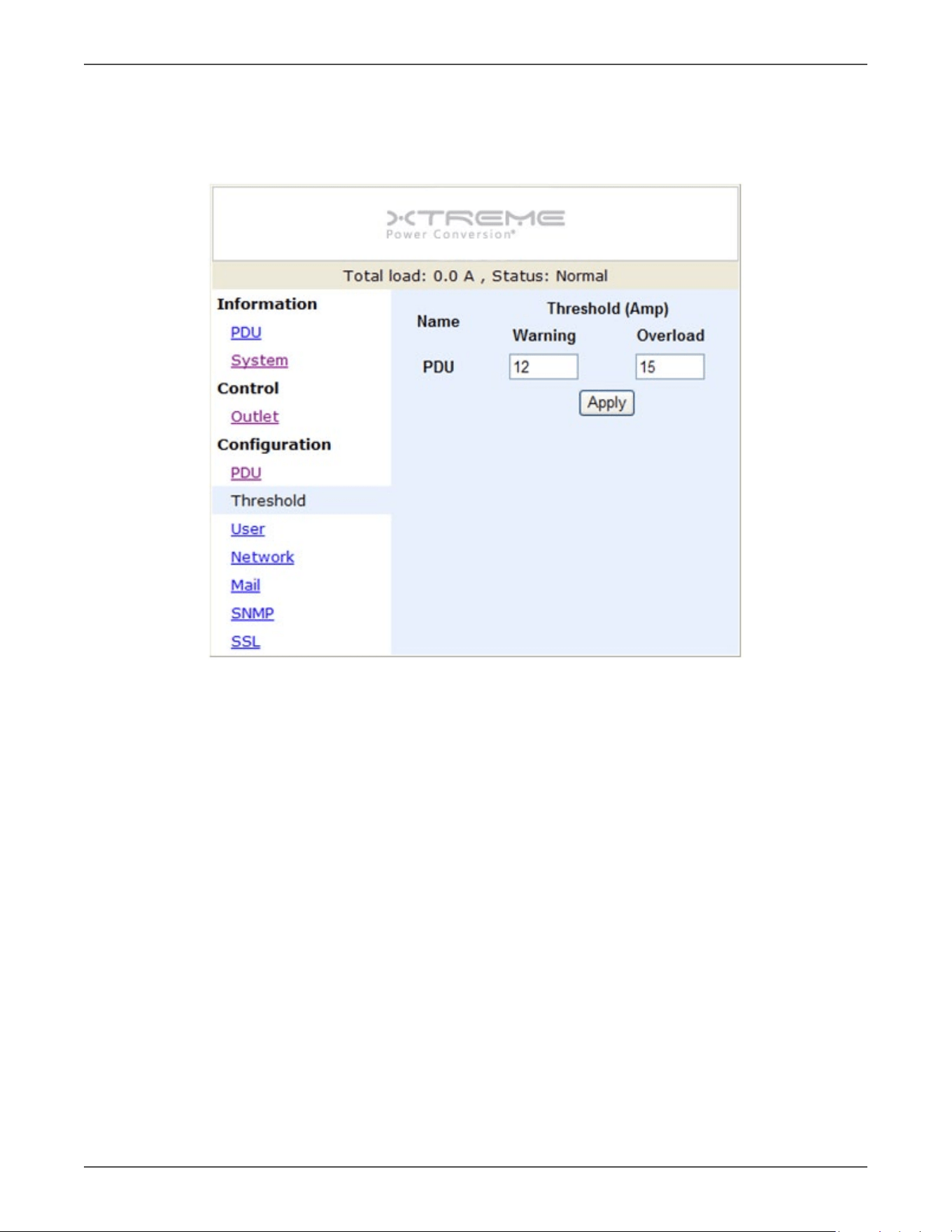
Conguraon: Threshold
Set the warning and overload threshold for each circuit.
Set lower and upper threshold for temperature and humidity.
Xtreme Power Conversion Corporaon
Switched XPDU User’s Manual
Page 12
Power Distribuon Unit
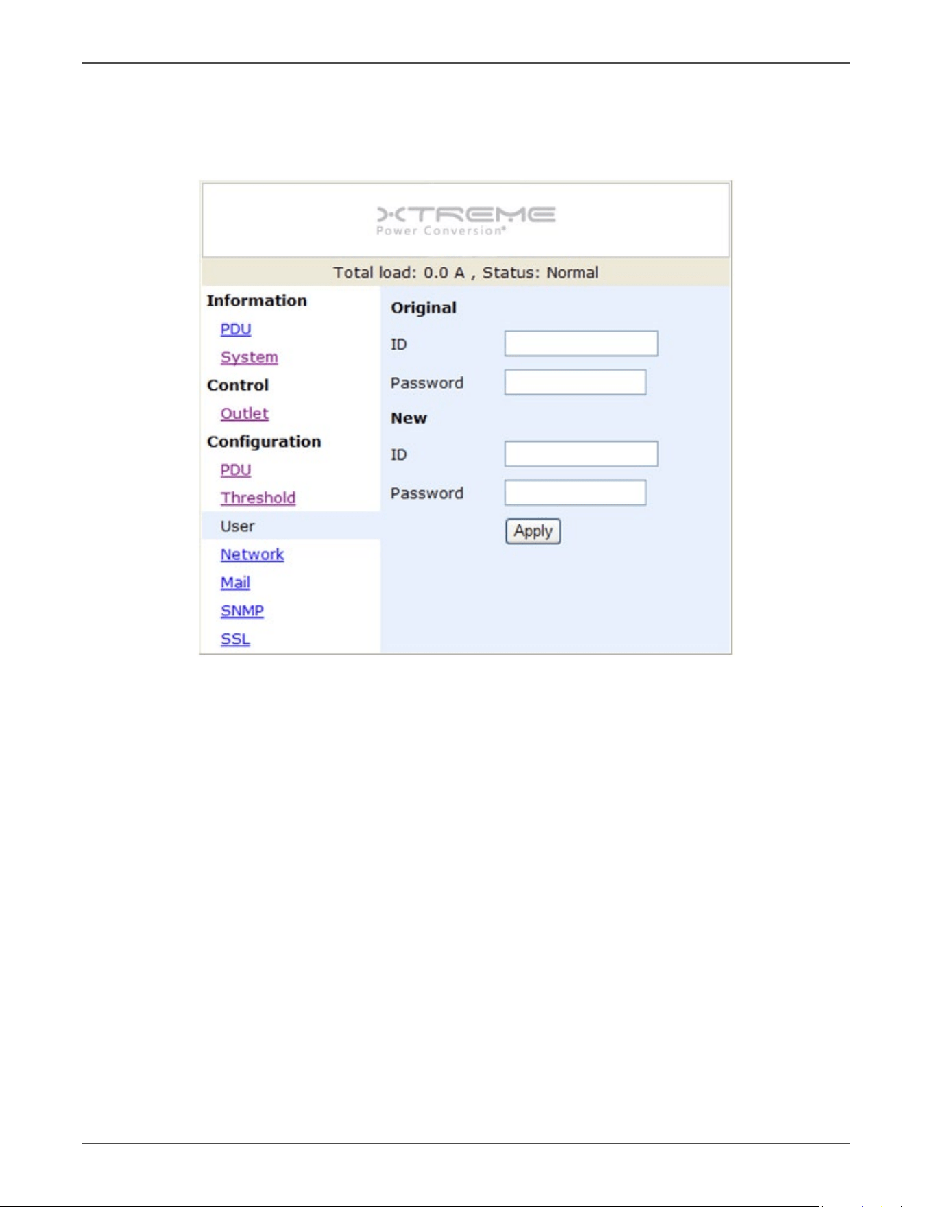
Conguraon: User
Change ID and password.
Default ID is snmp and password is 1234.
Xtreme Power Conversion Corporaon
Switched XPDU User’s Manual
Page 13
Power Distribuon Unit
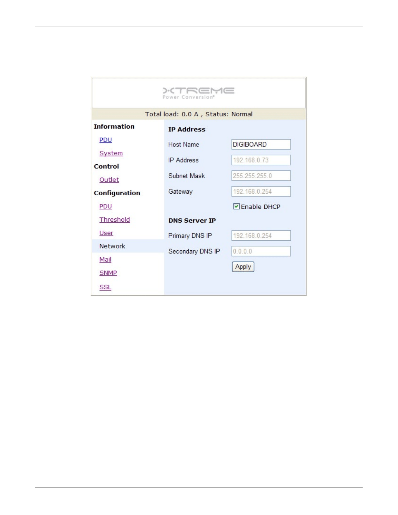
Conguraon: Network
PDU network informaon
Enable DHCP: Change the way to get IP address for PDU.
Xtreme Power Conversion Corporaon
Switched XPDU User’s Manual
Page 14
Power Distribuon Unit
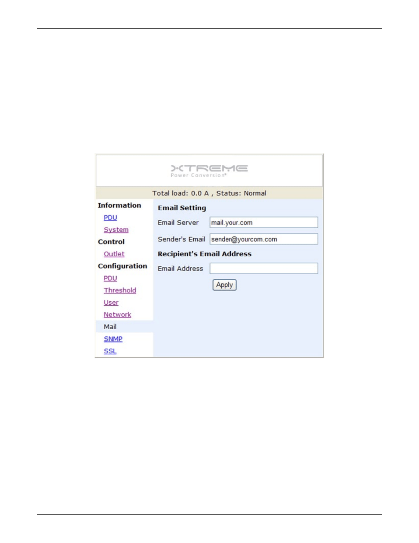
Conguraon: Mail
When event occurs, PDU can send out email message to pre-dened account.
Email Server: The Email Server only support to be input domain name, not IP address.
Sender’s Email: Input the sender email address.
Email Address: Input the recipient email address.
The message in the email:
Indicate OutletA~H-XXXXXXXX status in order
X=0 : means the power o. X=1 : means the power on.
Note: Make sure DNS server can resolve the Email Server’s domain name.
Xtreme Power Conversion Corporaon
Switched XPDU User’s Manual
Page 15
Power Distribuon Unit
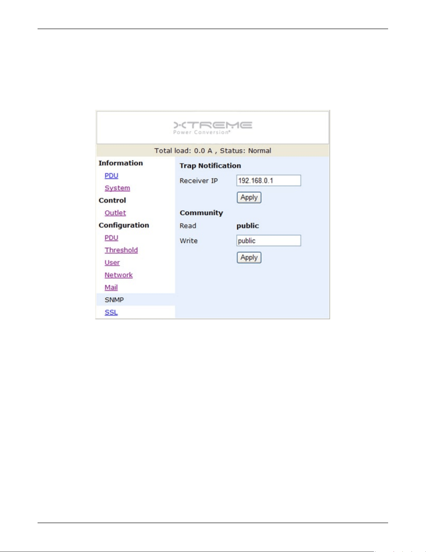
Conguraon: SNMP
When event occurs, PDU can send out trap message to pre-dened IP address.
Trap Nocaon: Set receiver IP for trap.
Community: Set SNMP community.
Read Community is public and xed.
Default Write Community is “public” and can be modied by user.
Xtreme Power Conversion Corporaon
Switched XPDU User’s Manual
Page 16
Power Distribuon Unit
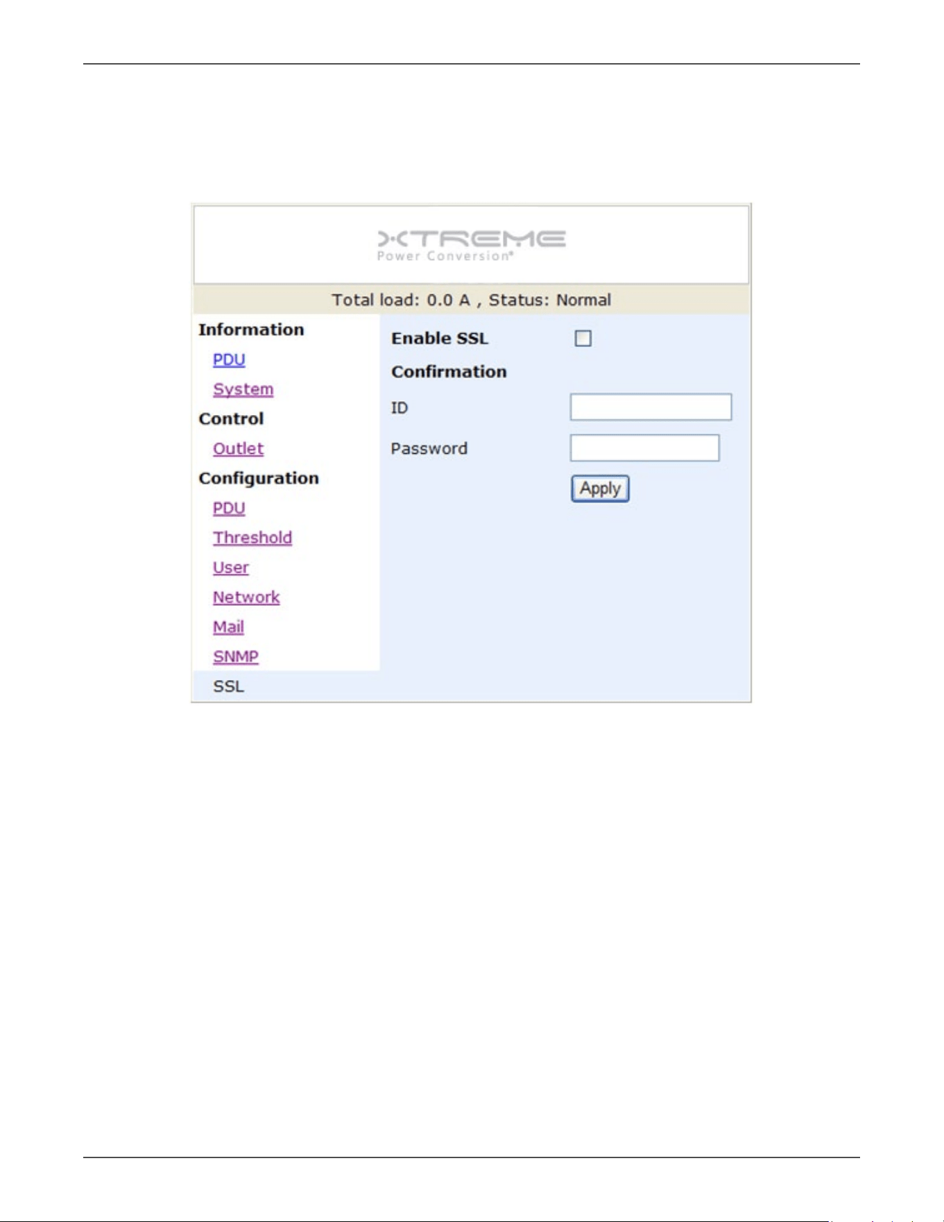
Conguraon: SSL
Enable SSL for web communicaon.
User must input the correct ID and password to enable SSL funcon. The ID and password must be the same with
the seng in “User”.