Read this manual carefully and never store it inside the safe!
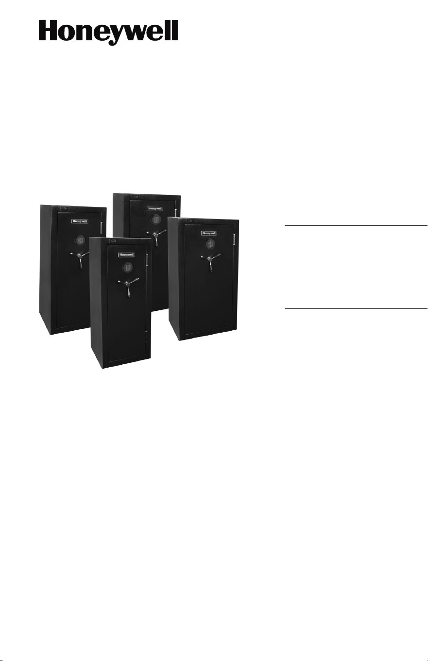
User Guide
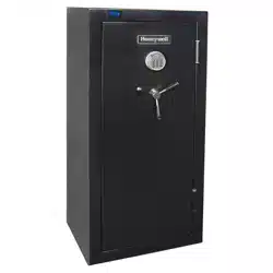
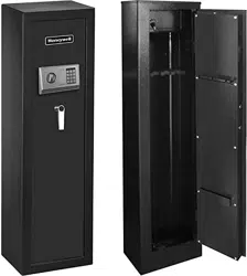
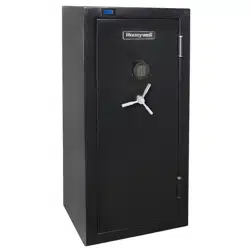
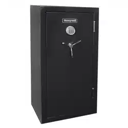
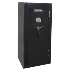
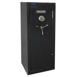
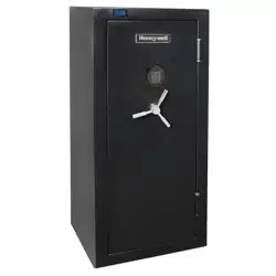
Executive / Long Gun Safe
with Temperature and Humidity Gauge
and Programmable Digital Lock
Package Includes;
Models 3014DG, 3018DG,
3024DG & 3032DG
ENGLISH
1 - Gun Safe with Digital Lock
1 - User Guide
2 - Override Access keys
1 - 9 volt battery
1 - Internal Storage Box
2 - Storage Box Access Keys
1 - Mounting Hardware Kit
Removable Gun Rack:
1 - Models 3014DG, 3018DG, 3024DG
2 - Model 3032DG
Removable Storage Shelf:
1 - Models 3014DG & 3018DG
3 - Models 3024DG
4 - Models 3032DG
Shelf Support Clips:
8 - Models 3014DG & 3018DG
16 - Model 3024DG
20 - Model 3032DG
DO NOT RETURN SAFE TO STORE
If you are missing parts or have difficulty operating your safe, please contact our
Consumer Assistance Department by telephone. Store will not accept returned
products without prior authorization. You must first contact our Consumer
Assistance Department (See page 13 for contact information).
Safe Serial #
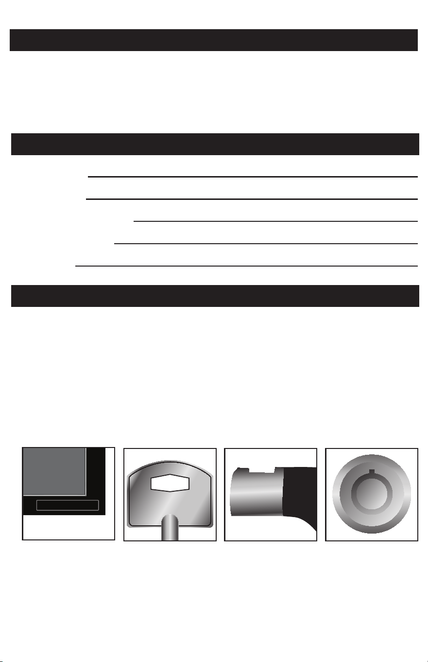
Located on the bottom right corner of the safe door frame (Figure 1.1).
Override Access Key #
Engraved on the Head of the key (Figure 1.2).
Storage Box Key #
Engraved on key barrel and the lock cylinder (Figures 1.3 & 1.4).
Safe Model #
Safe Serial #
Override Access Key #
Storage Box Key #
User Code
LOCATING SAFE IDENTIFICATION NUMBERS
SAFE IDENTIFICATION RECORD
Figure 1.1 Figure 1.2 Figure 1.3 Figure 1.4
LP0004 1375 0001 5101
020
9701
701

SAFE IDENTIFICATION RECORD ............................................................. INSIDE COVER
LOCATING SAFE IDENTIFICATION NUMBERS ........................... INSIDE COVER
INDEX ..................................................................................................................... PAGE 1
WELCOME ............................................................................................................ PAGE 2
PROPERER SAFE USE ....................................................................................... PAGE 2
CARE AND MAINTENANCE .............................................................................. PAGE 2
SAFETY PRECAUTIONS ..................................................................................... PAGE 3
MOVING YOUR SAFE ......................................................................................... PAGE 3
PLACEMENT OF SAFE ...................................................................................... PAGE 3
METAL SHIPPING LEGS ................................................................................... PAGE 4
INSTALL THE LOCK BATTERY ......................................................................... PAGE 5
LOW BATTERY WARNING ................................................................................. PAGE 5
REPLACING LOW OR DEAD BATTERY .......................................................... PAGE 5
OPEN SAFE USING PRESET FACTORY CODE ............................................ PAGE 6
INSTALL SPINDLES ON HANDLE .................................................................. PAGE 6
CLOSE & LOCK THE SAFE ................................................................................ PAGE 6
PROGRAM NEW USER CODE .......................................................................... PAGE 7
TEST NEW USER CODE ..................................................................................... PAGE 8
REPROGRAM USER CODE ............................................................................... PAGE 8
LOST OR FORGOTTEN USER CODE .............................................................. PAGE 8
SECURE LOCKOUT PERIOD ............................................................................ PAGE 9
OVERRIDE ACCESS KEY ................................................................................... PAGE 9
TEMPERATURE AND HUMIDITY GAUGE ....................................................... PAGE 10
REPLACING HUMIDITY GAUGE BATTERY ................................................... PAGE 10
GUN RACK AND SHELVES ................................................................................ PAGE 11
LOCKING STORAGE BOX .................................................................................. PAGE 11
ANCHORING YOUR SAFE ................................................................................. PAGE 12
CONTACTING CONSUMER ASSISTANCE ..................................................... PAGE 13
ORDER REPLACEMENT KEYS ........................................................................ PAGE 14
LIMITED WARRANTY ......................................................................................... PAGE 15
INDEX

PROPER SAFE USE
CARE AND MAINTENANCE
Your Honeywell Executive /Long Gun Safe will provide years of safe and secure
protection for your valuables, important documents and other personal items.
All Honeywell safes are designed and built using the highest manufacturing
standards to ensure maximum user satisfaction under a variety of conditions.
With proper care, your Honeywell safe will provide “Peace of Mind” for many
years to come.
Thank you and enjoy!
WELCOME
Honeywell Executive/Long Gun Safes are designed to protect firearms and
other valuables from theft and tampering as well as damage from the exposure
to fire.
Theft Protection
A Programmable Digital Lock, Steel Locking Door Bolts, Solid Steel Walls and
Bolt-Down Hardware to secure the safe to the floor are designed to prevent any
unauthorized access.
Fire Protection
Independent testing verified the interior temperature remains below 350º F
(177ºC) when the exterior temperature is up to 1400º F (760ºC) for 30 minutes.
Climate Monitoring
A Built-in Temperature and Humidity Gauge increases awareness when internal
conditions may cause damage to the metal and wood components in long guns.
When properly maintained, your safe will continue to operate for many years. In
order to ensure optimum performance of your safe, please follow these simple
precautions:
Clean Hands
Never attempt to operate the digital keypad if your hands have excessive dirt,
debris or liquids on them.
Clean Safe
To clean the surface of your safe, it is recommended that you use a mild cleaner
(e.g., window cleaner) to avoid scratching or discoloring the surface. Always wipe
dry and NEVER use abrasive cleansers on the safe or digital keypad.
Moisture
We recommend that you place delicate items such as pictures or intricate
jewelry into an air-tight container before storing them in your safe. Avoid placing
your safe in areas of high humidity.
2

SAFETY PRECAUTIONS
MOVING YOUR SAFE
PLACEMENT OF SAFE
The safe door is heavy. Do not open the door with the safe on an uneven or
unstable floor. Hanging on an open door may cause the safe to tip forward when
not secured to a wall or the floor, resulting in serious injury or death to yourself
or others. If you have small children in your home, please make sure you never
leave your safe unsecured. It is possible for small children to climb inside your
safe and become locked in. This could result in serious injury or death.
Before moving your safe, verify the load bearing weight of the floors and stairs,
and types of flooring the safe will be moved over (tile, wood, and other flooring
can be damaged by the weight of the safe). You should first measure and
confirm that your safe will make it through doorways, stairs or corners and will
fit all the way through to its final location.
Proper installation and anchoring are critical to the security of your safe. Install
near a load-bearing wall to support the weight of the safe. To help protect the
exterior finish of your safe, install inside in a dry location where there is climate
control (heat in the winter and cooling in the summer). This safe has been de-
signed to withstand a certain amount of heat during a fire. Generally speaking,
fire safes perform better in lower levels of a home (like the basement) where fire
temperatures are lower. Additionally, placement of your safe away from potential
hot spots (areas where flammable materials are stored) will improve your
chances that your safe and its contents will perform better in a home fire. No
safe is completely fireproof. If the fire reaches a high enough temperature for
long periods, fire damage will occur.
3
4
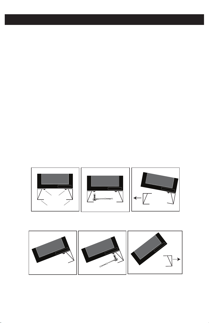
METAL SHIPPING LEGS
Your new safe is bolted to heavy duty metal shipping legs. These legs are de-
signed to protect the safe during shipment and transportation of the safe to the
final position for use. To avoid unnecessary damage to the safe exterior, the metal
legs should be only removed after the safe has been placed in the desired loca-
tion. See below for removal instructions.
Remove Metal Shipping Legs
1. Locate the bolts that secure the legs to the bottom of the safe (Figure 2.1)
2. Remove the 2 bolts on one side of the safe with a 17 mm socket wrench (Figure 2.2)
3. Carefully tilt the safe away from the unbolted side and pull the leg out from under
the safe (Figure 2.3).
4. Carefully tilt the safe back down until it resting on angle (Figure 2.4).
5. Remove the 2 bolts on the other side of the safe (Figure 2.5).
6. Carefully tilt the safe just enough to allow removal of the remaining leg (Figure 2.6).
7. Gently tilt the safe so it resting flat on the floor.
TIP: It is recommended that you store the metal shipping legs in the event the
safe must be transported to another location in the future.
Figure 2.1 Figure 2.2 Figure 2.3
LP0004 1375 0001 5101
Bolts
Shipping Legs
LP0004 1375 0001 5101
LP0004 1375 0001 5101
Figure 2.4 Figure 2.5 Figure 2.6
LP0004 1375 0001 5101
LP0004 1375 0001 5101
LP0004 1375 0001 5101
8
0
5
2
7
4
1
9
#
6
3
A EBCD
IJK LMNFGH
RST UVWOPQ
XYZ
5
INSTALL THE LOCK BATTERY
LOW BATTERY WARNING
REPLACING LOW OR DEAD LOCK BATTERY
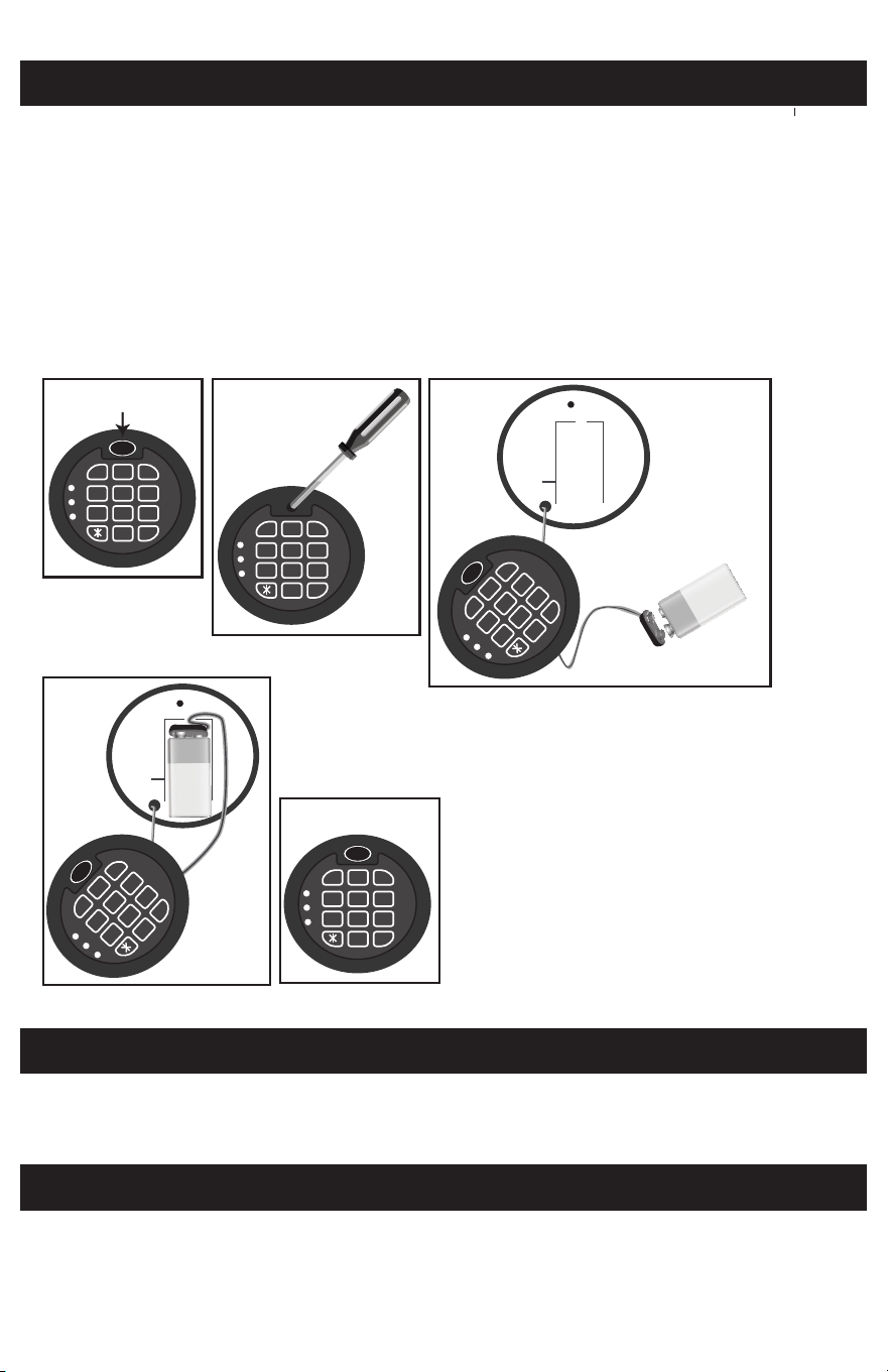
Your safe requires a 9-volt alkaline battery (included) to power the electronic
locking system. Remove the supplied battery from the bag that contained this
User’s Guide and follow the steps for proper installation:
1. Remove the gel label located at top of the keypad (Figure 3.1).
2. Remove the Phillips head screw located under the label (Figure 3.2).
3. Gently pull the keypad cover off and let it hang down (Figure 3.3).
4. Install the 9 volt battery onto the battery terminal wire (Figure 3.3).
5. Place the attached battery and wire into the lock base (Figure 3.4).
6. Replace the keypad cover and screw, and then replace the Gel cover (Figure 3.5).
If the green and yellow lights are on and the keypad beeps when opening the safe,
the battery is low and should be replaced.
Follow the same steps as above to replace the lock battery. The pass code will not
be erased if the batteries become weak or are removed. Dead or weak batteries
should always be removed promptly.
Figure 3.4
Figure 3.1
8
0
5
2
7
4
1
9
#
6
3
A EBCD
IJK LMNFGH
RST UVWOPQ
XYZ
Figure 3.2
8
0
5
2
7
4
1
9
#
6
3
A EBCD
IJK LMNFGH
RST UVWOPQ
XYZ
Figure 3.3
8
0
5
2
7
4
1
9
#
6
3
A EBCD
IJK LMNFGH
RST UVWOPQ
XYZ
Figure 3.5
8
0
5
2
7
4
1
9
#
6
3
A EBCD
IJK LMNFGH
RST UVWOPQ
XYZ
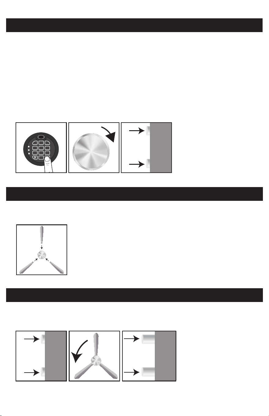
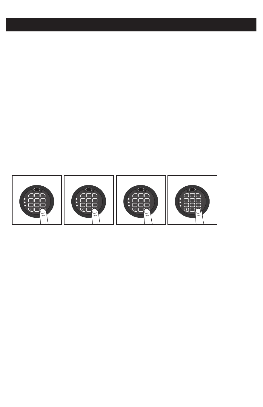
OPEN SAFE USING PRESET FACTORY CODE
IMPORTANT: The three (3) spindles that attach to the handle have been shipped
inside the safe and should be installed onto the handle after unlocking and opening
the new safe for the first time. The Handle can be operated without the spindles by
turning it like a door knob. Make sure the handle is turned all the way the left
(counterclockwise) before entering a code.
1. Enter the preset factory code “1-2-3- 4- 5-6”. You will hear two (2) beeps and the
green LED will flash (Figure 4.1).
2. Rotate the handle to the right (clockwise) to open the door (Figures 4.2 & 4.3).
NOTE: If the incorrect code is entered, the keypad will beep (5) times and the red
LED will light.
6
INSTALL SPINDLES ON HANDLE
CLOSE AND LOCK THE SAFE
Insert the three (3) spindles into the holes located on the side of the handle and
screw to the right (clockwise) by hand until they are snug in the handle (Figure 5.1).
1. Make sure that the locking door bolts are retracted in the open position (Figure 6 .1).
2. Push the door closed and rotate the handle to the left (counter clockwise) to
extend the locking bolts and lock the safe (Figures 6.2 & 6.3).
Figure 4.1
Figure 5.1
Figure 6.1
Figure 4.2
Figure 6.2
Figure 4.3
Figure 6.3
8
0
5
2
7
4
1
9
#
6
3
A EBCD
IJK LMNFGH
RST UVWOPQ
XYZ
1-2-3-4-5-6
7
PROGRAM NEW USER CODE
It is important to program a new user code as soon as possible. The factory preset
code should only be used as you familiarize yourself with your new safe. Begin by
selecting a new 6 digit User Code to replace the factory preset code and make sure to
write it the Safe Identification Record on the Inside Front Cover of this Manual.
IMPORTANT: Each step must be performed within 5 seconds or the process will
be cancelled and you must begin again. The door must be open with the locking
door bolts in the retracted (unlocked) position.
1. Enter the reset code “0-0-0-0-0-0” (Figure 7.1).
You will hear two (2) beeps and the green LED will flash.
2. Enter the factory code “1-2-3-4-5-6” (Figure 7.2).
You will hear two (2) beeps and the green LED will flash.
3. Enter your new 6 digit user code “X-X-X-X-X-X” (Figure 7.3).
You will hear two (2) beeps and the green LED will flash.
4. Enter your new 6 digit user code a second time “X-X-X-X-X-X” (Figure 7.4).
You will hear two (2) beeps and the green LED will flash.
Your New User Code is programmed and the preset factory code will not open the safe.
IMPORTANT: Do not close and lock the door until you have tested the new user code.
Figure 7.1 Figure 7.2 Figure 7.3 Figure 7.4
8
0
5
2
7
4
1
9
#
6
3
A EBCD
IJK LMNFGH
RST UVWOPQ
XYZ
8
0
5
2
7
4
1
9
#
6
3
A EBCD
IJK LMNFGH
RST UVWOPQ
XYZ
8
0
5
2
7
4
1
9
#
6
3
A EBCD
IJK LMNFGH
RST UVWOPQ
XYZ
8
0
5
2
7
4
1
9
#
6
3
A EBCD
IJK LMNFGH
RST UVWOPQ
XYZ
0-0-0-0-0-0 1-2-3-4-5-6 X-X-X-X-X-X X-X-X-X-X-X

8
TEST NEW USER CODE
REPROGRAM USER CODE
LOST OR FORGOTTEN USER CODES
The door should still be open to test your new user code.
1. Rotate the handle to the left (counterclockwise) to extend the locking door
bolts into the locked position. (Figure 8.1).
2. Enter your new 6 digit user code “X-X-X-X-X-X”. You will hear two (2) beeps
and the green LED will flash. (Figure 8.2)
3. Rotate the handle to the right (clockwise) and the locking door bolts should
recede into the unlocked position. (Figures 8.3 & 8.4))
At anytime you can change the programmed user code by following the previ-
ous procedure using the current user code in place of the factory preset code
for step 2.
If you have lost or forgotten the active user code(s), you must contact consumer
assistance to receive authorization and instructions for reprogramming code(s).
You may open the safe using the Emergency Override Key by following the
instructions on the next page.
Figure 8.1 Figure 8.2
Figure 8.3
Figure 8.4
8
0
5
2
7
4
1
9
#
6
3
A EBCD
IJK LMNFGH
RST UVWOPQ
XYZ
X-X-X-X-X-X
9
SECURE LOCKOUT PERIOD
OVERIDE ACCESS KEY
If an incorrect user code is entered three (3) consecutive times, the keypad will
revert to “lockout mode” and you will be unable to open the safe using the keypad
for five (5) minutes. If continued attempts are made to enter the safe using the
wrong entry code, additional five (5) minute lockout periods will occur.
HINT: If necessary, during the lockout period, entry can be made using the
emergency override access key.
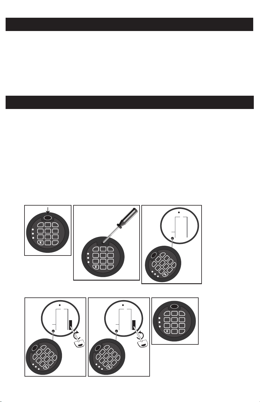
If for any reason your User Code does not open the safe or the battery is weak and will no
longer operate the key pad, entry to the safe can be made using the Emergency Override
Key. The following procedure is required to gain entry using the key.
1. Remove the gel label located at top of the keypad (Figure 9.1).
2. Remove the Phillips head screw located under the label (Figure 9.2).
3. Gently pull the keypad cover off and let it hang down (Figure 9.3).
4. Insert the long key into the key slot and rotate to the right (clockwise) to
unlock and open the safe (Figure 9.4),
5. To lock the safe turn the Key to the left (counterclockwise) (Figure 9.5).
6. Remove the key and store in a secure place
7. Replace the keypad cover and screw, and then replace the Gel cover (Figure 9.6).
Figure 9.1
Figure 9.2
Figure 9.3
Figure 9.4 Figure 9.5
Figure 9.6
8
0
5
2
7
4
1
9
#
6
3
A EBCD
IJK LMNFGH
RST UVWOPQ
XYZ
8
0
5
2
7
4
1
9
#
6
3
A EBCD
IJK LMNFGH
RST UVWOPQ
XYZ
8
0
5
2
7
4
1
9
#
6
3
A EBCD
IJK LMNFGH
RST UVWOPQ
XYZ
8
0
5
2
7
4
1
9
#
6
3
A EBCD
IJK LMNFGH
RST UVWOPQ
XYZ
8
0
5
2
7
4
1
9
#
6
3
A EBCD
IJK LMNFGH
RST UVWOPQ
XYZ
8
0
5
2
7
4
1
9
#
6
3
A EBCD
IJK LMNFGH
RST UVWOPQ
XYZ
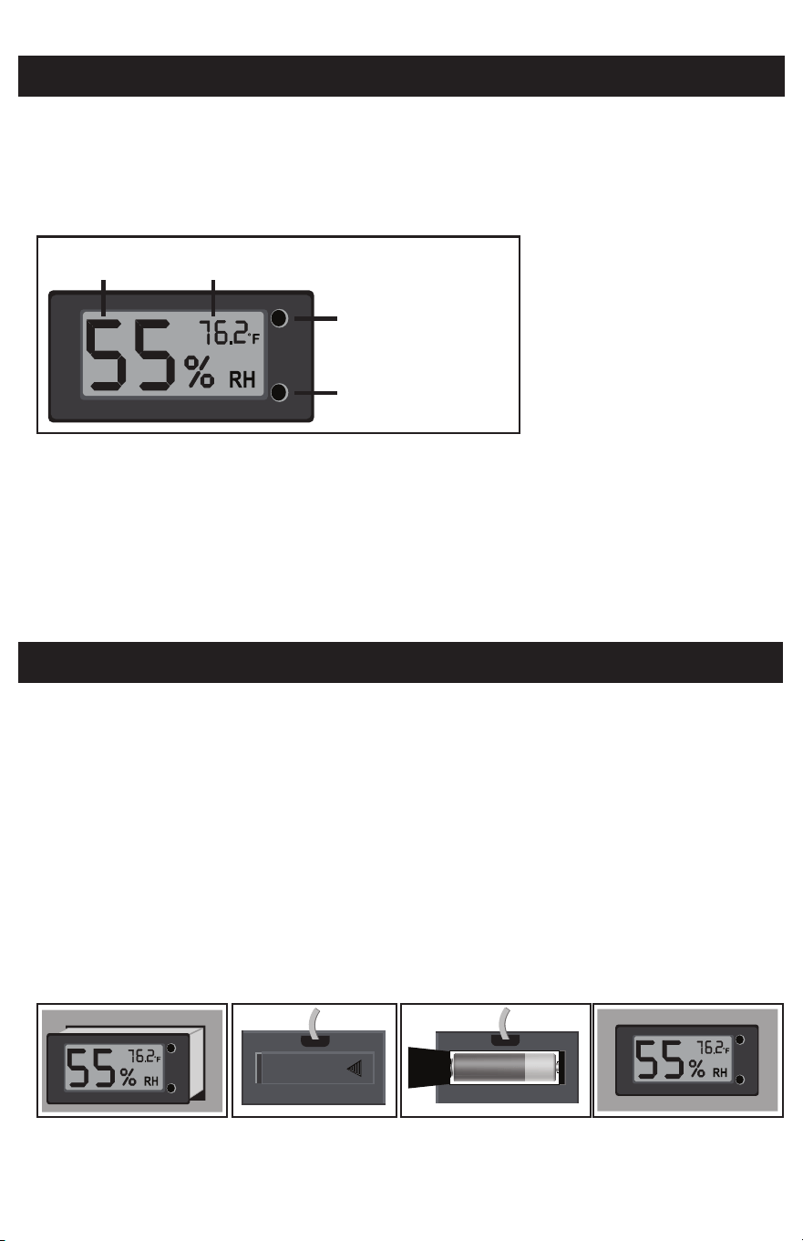
CLIMATE MONITORING
For your convenience and added protection of your safes contents, this
Honeywell safe is equipped with a digital thermometer and hygrometer that
continually monitors and displays the interior temperature and humidity on an
LCD display gauge located above the left side of the door.
Turn Backlight On/Off
The backlight makes it easier to read in low light environments. You can activate
the backlight by pressing the button located on the bottom right side of LCD
Display (Figure 10.1 - A).
Set Celsius or Fahrenheit
You can change the temperature display to show the temperature in either Cel-
sius or Fahrenheit by pressing the button located on the top at right side of the
LCD display (Figure 10.1 - B).
TEMPERATURE AND HUMIDITY GAUGE
10
REPLACING HUMIDITY GAUGE BATTERY
The LCD Humidity / Temperature gauge operates on a single AAA battery. If
the battery is low or dead, follow the steps below to access the gauge battery
compartment and replace the battery.
1. Remove the LCD display from the safe by lifting the edges and pulling
forward and out (Figure 11.1).
2. Carefully slide the battery compartment cover to the right and open up the
hinged cover (Figure 11.2).
3. Remove and replace the AAA battery and then close the cover and slide back
into the locked position (Figure 11.3).
4. Position the Display Gauge back over the mounting hole and carefully push
back into position (Figure 11.4).
Figure 10.1
Figure 11.1 Figure 11.2 Figure 11.3 Figure 11.4
Humidity
Gauge
Temperature
Gauge
Celsius/
Fahrenheit
Button
Back
Light
Button
A
B
For your convenience, this safe includes an interior shelf and gun rack that are
removable. Follow these steps to remove or adjust the interior shelves :
1. Remove the shelf from by lifting it off the support clips (tilting if necessary)
and removing it from the safe (Figure 12.1).
2. Remove the support clips (Figure 12.2).
3. To reposition the shelf, place the support clips into the selected slot, top first
and then the bottom of clip will lock in place when pushed back (Figure 12.3).
4. IMPORTANT: Make sure all clips are installed at the same height on the verti
cal standards so that the shelf is level.
5. Install the shelf into position by placing inside the safe (tilting if necessary)
and lowering into position on the support clips (Figure 12.4).
The safe storage of ammunition in now mandated by many states nationally and
many countries internationally. This safe includes a removable storage box that
can be stored inside the safe or it it can easily be transported using the
convenient carry handle.
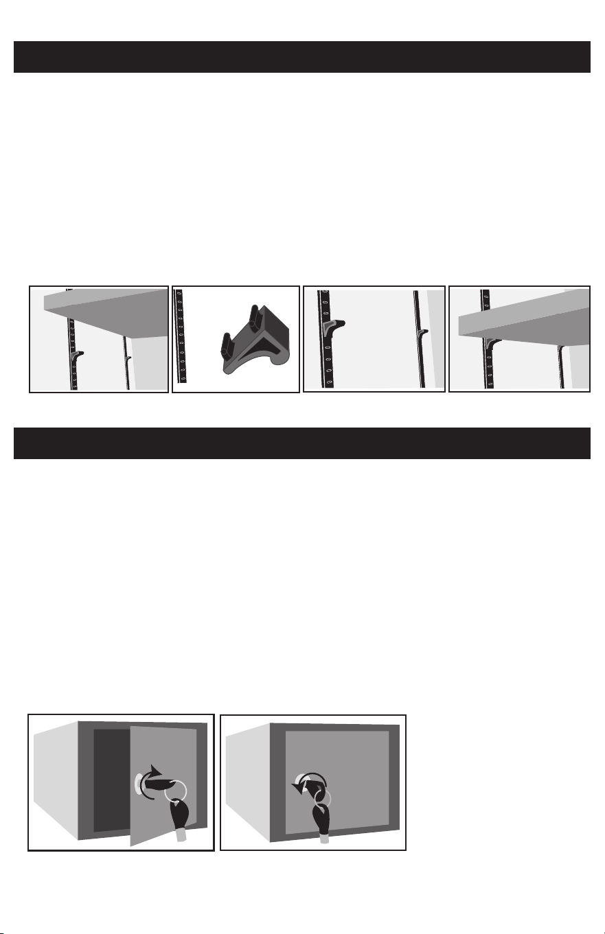
It is equipped with a security key lock for additional safety. The key number is
located on the key barrel and the lock cylinder. This number should be recorded
in the Safe Identification Record on Page 1 for future reference.
To Unlock & Open
Insert the key and turn fully to the right (clockwise) and pull the door open (Figure 13.1).
To Close & Lock
Push the door to the closed position and turn the key to the left (counterclockwise)
until it stops. Remove the key and store in a safe place away from the safe (Figure 13.2).
GUN RACK AND SHELVES
REMOVABLE STORAGE BOX
11
Figure 13.1
Figure 12.1
Figure 13.2
Figure 12.2 Figure 12.3 Figure 12.4
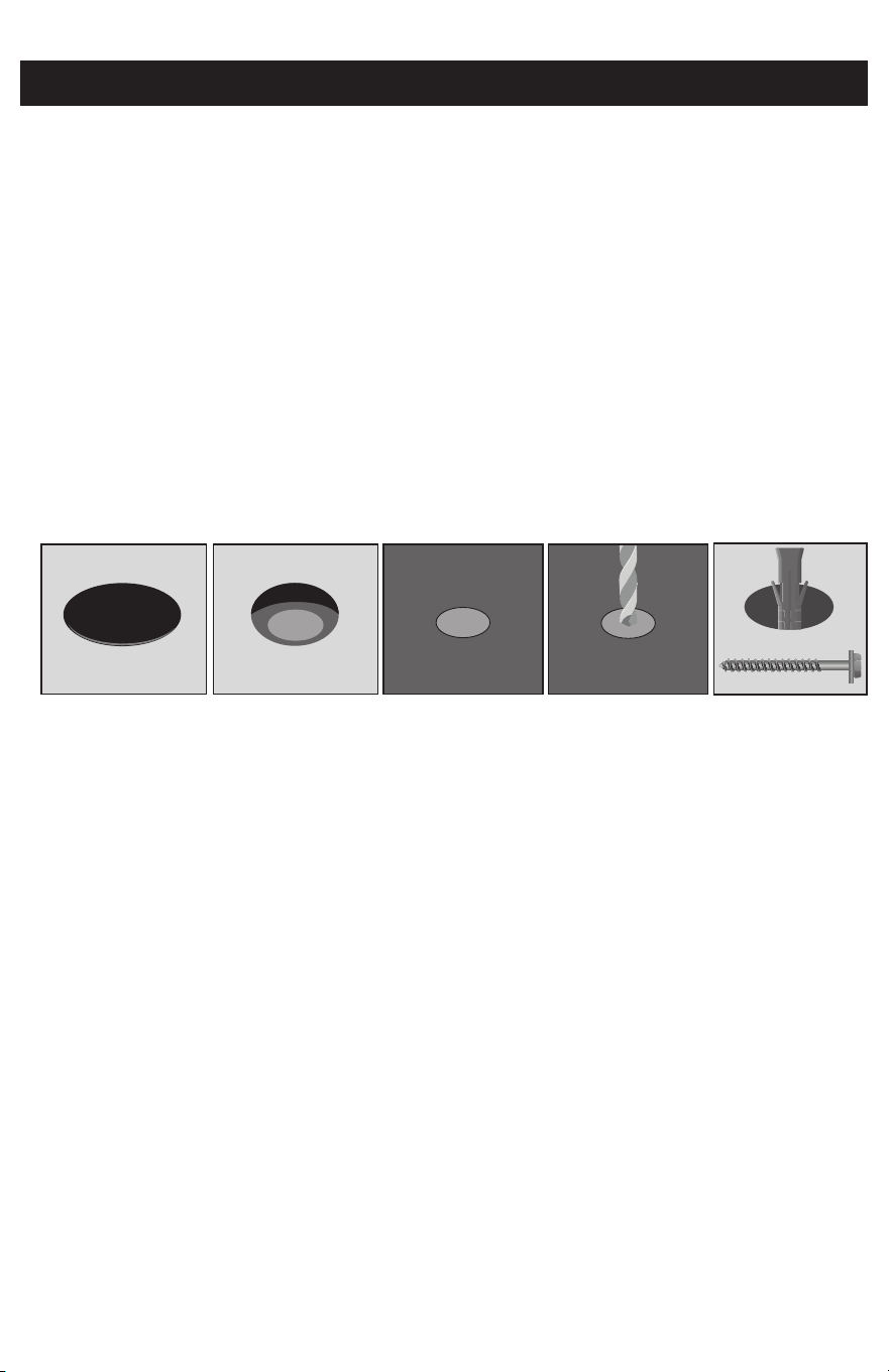
ANCHORING YOUR SAFE
You may bolt your safe to floor for added theft protection and resistance to
tipping. Your safe has a pre-drilled bolt-down hole in the floor panel and mount-
ing hardware is provided for securing to concrete surfaces. If bolting to wood or
metal additional hardware will be needed. Check with your local home center.
1. To secure the safe to a concrete floor:
2. Place your safe in the desired location for mounting.
3. Empty the safe and remove the plastic caps covering the predrilled holes on
the bottom of the safe (Figure 14.1).
4. Make a mark through the hole onto the floor surface creating a drilling guide
(Figure 14.2).
5. Move the safe aside to clear the marked spot for drilling (Figure 14.3).
6. Then drill a 5/8 in./16mm diameter hole with a depth of 2 1/8 in./54mm and
remove any excess dust (Figure 14.4).
7. Place the safe back into position lined up over the hole and secure in place
using the provided mounting bolt (Figure 14.5).
NOTE: Bolting and unbolting of the unit is at the consumer’s expense and dis-
cretion. LH Licensed Products is not responsible for any costs incurred. If you
have any questions about mounting the safe, please check with your local home
center/hardware retailer or independent contractor.
12
Figure 14.1 Figure 14.2 Figure 14.3 Figure 14.4 Figure 14.5

13
CONSUMER ASSISTANCE
EMAIL: LHLPCustomerSer[email protected]
WEBSITE: www.honeywellsafes.com
ADDRESS: Consumer Assistance Dept.
LH Licensed Products, Inc.
860 East Sandhill Avenue
Carson, CA 90746 USA
TELEPHONE: US/Canada 1-877-354-5457 (Toll Free)
Mexico 01-800-288-2872 After English voice recording stops you must
then enter 800-860-1677 to complete your call. (Toll Free)
Australia 0011-800-5325-7000 (Toll Free)
Germany/New Zealand 00-800-5325-7000 (Toll Free)
Other Countries XX*-310-323-5722 (Toll Charges Apply)
XX*- Dial U.S. Country Code first
CALL CENTER HOURS:
US/Canada 7am – 5pm (PST**) Mon – Fri (Subject to change)
CALL BACK HOURS:
Other Countries 7am – 8pm (PST**) Mon – Fri (Subject to change)
PST**- Local time in Los Angeles, CA, USA
INTERNATIONAL CALL BACK HOURS:
If you need to speak with a consumer assistant and cannot contact us
during the Call Center hours above, please send an email or leave a
telephone message, including your Name, Telephone Number and the best
time for us to contact you during the Call Back hours above and we will
make every effort to contact you and help answer any of your questions or
concerns.
* Insert correct Country Code
** Local Time based on Los Angeles California USA

14
M3014D G 3018DG 3024DG G3032DG www.honeywellsafes.com
The following information is required to order keys:
1. PROOF OF OWNERSHIP (1 of 2 Options Below)
A) SALES RECEIPT & IDENTIFICATION – INTERNATIONAL ORDERS ONLY!
•CopyofsalesreceiptshowingStore,Date&ProductDescription.
•CopyofyourpictureI.D.(Driverslicense,passport,regularI.D.).
B) PRODUCT OWNERSHIP VERIFICATION FORM
If sales receipt is not available, contact us by email or telephone to
request a “Product Ownership Verification Form”.
2. ORDER INFORMATION
CONTACT
•Name&ShippingAddress
•E-mailaddress(IfAvailable)
•TelephoneNumber
•BestTimetoContactYou
3. PLACING AN ORDER
•Tobegintheorderprocess,contactusbytelephone,email,ormail
4. METHOD OF PAYMENT
•Visa,MasterCard,CheckorMoneyOrder
NOTE: For pricing please contact Consumer Assistance. Contact information is
located on the back cover of this manual. Payment method and pricing subject
to change.
ORDERING ADDITIONAL SAFE / STORAGE BOX KEYS
PRODUCT
•SafeModel#
•SafeSerial#
•LockKey#
•QuantityofKeysOrdered

LIMITED WARRANTY
LH Licensed Products, Inc., (“LHLP, Inc.”) warrants that for a period of seven (7) years from the date
of purchase, this product will be free from structural or mechanical defects resulting from materials
or workmanship. LHLP, Inc., at its sole option and as the purchaser’s sole remedy under this
warranty, will repair or replace this product or any component of the product found to be defective
during the warranty period. Replacement or repair will be made with a new or remanufactured
product or component. If the product is no longer available, replacement may be made with a
similar product of equal or greater value.
THIS IS YOUR EXCLUSIVE WARRANTY.
Our goods come with guarantees that cannot be excluded under the Australian Consumer Law.
You are entitled to a replacement or refund for a major failure and for compensation for any other
reasonably foreseeable loss or damage. You are also entitled to have the goods repaired or replaced
if the goods fail to be of acceptable quality and the failure does not amount to a major failure.
This warranty is only valid for the original retail purchaser from the date of initial retail purchase and
is not transferable. You must keep the original sales receipt. Proof of purchase is required to obtain
warranty service.
LHLP, Inc. dealers, service centers, or retail stores selling this product do not have the right to alter,
modify or in any way change the terms and conditions of this warranty.
This warranty does not apply to the finish on the product. This warranty does not cover normal wear
and tear of parts or damage resulting from any of the following: negligent use or misuse of the
product, use contrary to the operating instructions, disassembly, repair or alteration by anyone other
than LHLP, Inc. or an authorized service center, improper installation, or exposure to extremes of
heat or humidity. Further, the warranty does not cover Acts of God, such as fire, flood, earthquakes,
hurricanes and tornadoes.
LHLP, Inc. shall not be liable for any incidental or consequential damages caused by the breach of
any express or implied warranty or otherwise relating to the sale of this product. LHLP, Inc. is also
not responsible for: costs associated with removing or installing the product; damage or loss of the
contents of the product; nor for the unauthorized removal of the contents; or damages incurred
during shipment.
THE ABOVE WARRANTY IS IN LIEU OF ALL OTHER WARRANTIES, EXPRESS OR IMPLIED,
INCLUDING ANY WARRANTIES OF MERCHANTABILITY OR FITNESS FOR A PARTICULAR
PURPOSE, AND LHLP, INC. DISCLAIMS ANY AND ALL OTHER COVENANTS AND WARRANTIES.
Except to the extent prohibited by applicable law, any implied warranty of merchantability or
fitness for a particular purpose is limited in duration to the duration of the above warranty period.
Some states, provinces or jurisdictions do not allow the exclusion or limitation of incidental
or consequential damages or limitations on how long an implied warranty lasts, so the above
limitations or exclusion may not apply to you. This warranty gives you specific legal rights, and you
may also have other rights that vary from state to state, or province to province, or jurisdiction to
jurisdiction.
15
Manufactured by:
LH Licensed Products, Inc.
860 East Sandhill Avenue
Carson, CA 90746
M3014D G 3018DG 3024DG G3032DG www.honeywellsafes.com
The Honeywell Trademark is used under license from Honeywell
International Inc. Honeywell International Inc. makes no
representations or warranties with respect to this product.