REV I DATE: 07/27/2023
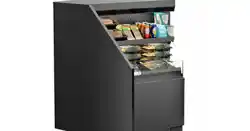
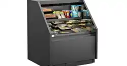
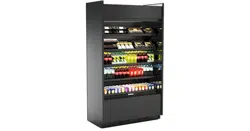
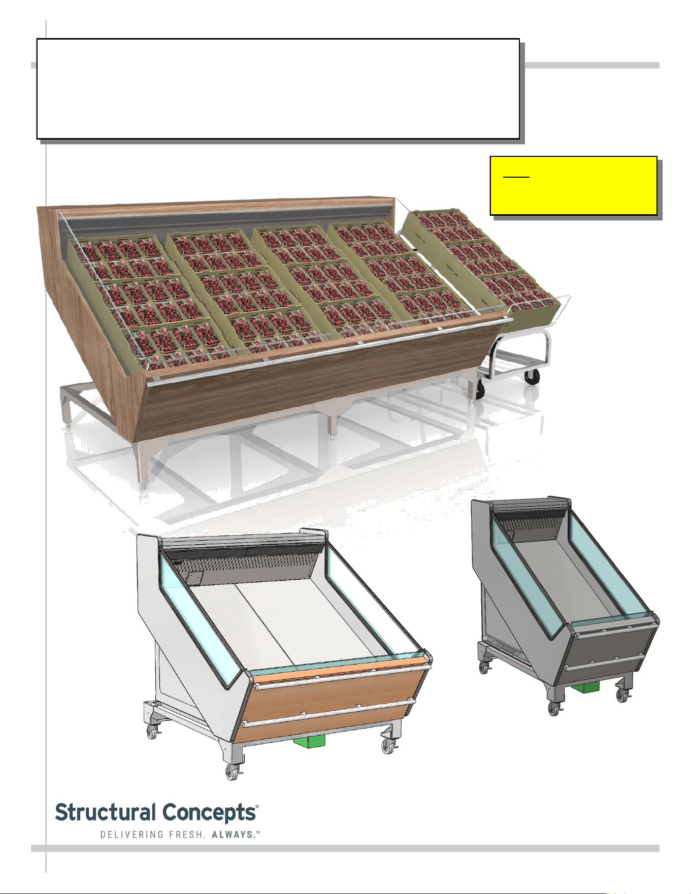
SELF-SERVICE REFRIGERATED CASES (BOTH SELF-CONTAINED & REMOTE)
>> DESIGNED FOR BERRY MERCHANDISING
USER MANUALS\20-45803_OASIS_USER MANUAL_FSIB(L)R_REF_MOBILE-STATIONARY_BERRY CASE
Model FSIB8R Shown Above
With Optional Product Crates
Model FSIB2R
Model FSIB4R
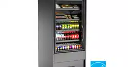
Separate Produce Unit Shown
Above-Right (On Casters) For
Illustrative Purposes Only
Note: See Page 8 Of This
Manual For Case-To-Case
Adjoinment Instructions.
SCC P/N
20-45803
Oasis
READ AND SAVE THESE INSTRUCTIONS
®
USER
MANUAL
Structural Concepts Corp. ∙ 888 E. Porter Rd ∙ Muskegon, MI 49441 Phone: 231.798.8888 Fax: 231.798.4960 ∙ www.structuralconcepts.com
2
TABLE OF CONTENTS
OVERVIEW / TYPE / COMPLIANCE / WARNINGS / PRECAUTIONS / WIRING / CORDS / PLUGS.
SHIPPING BRACKETS / CASE REMOVAL FROM SKID - REMOTE UNITS ..………………………....
SHIPPING BRACKETS / CASE REMOVAL FROM SKID - SELF-CONTAINED UNITS ……………...
POSITIONING & ALIGNING / ADJUSTING LEVELERS / LOCKING CASTERS IN PLACE …….…...
ADJOINING CASES - MODEL FSIB8R SHOWN FOR ILLUSTRATIVE PURPOSES ONLY ………...
MERCHANDISER START-UP / THERMOMETER / DISCHARGE AIR PROBES ………………….…..
HONEYCOMB AIR DIFFUSER / AIR RETURN DUCT / REFRIGERATED AIRFLOW PATH ………...
EVAPORATOR AREA: DECK PAN REMOVAL / REFRIG. COMPONENTS FOR FSIB8R …………..
EVAPORATOR AREA: DECK PAN REMOVAL / REFRIG. COMPONENTS FOR FSIB2R ……….….
ELECTRICAL LAYOUT: MODEL FSIB8R REMOTE & SELF-CONTAINED UNITS .…………………..
ELECTRICAL LAYOUT: MODEL FSIB4R SELF-CONTAINED UNITS ONLY ………………………….
ELECTRICAL LAYOUT: MODEL FSIB2R SELF-CONTAINED UNITS ONLY ………………………….
CONDENSER PACKAGE LAYOUT: MODEL FSIB8R SELF-CONTAINED UNITS ONLY …..............
CONDENSER PACKAGE LAYOUT: MODEL FSIB4R SELF-CONTAINED UNITS ONLY ……………
CONDENSER PACKAGE LAYOUT: MODEL FSIB2R SELF-CONTAINED UNITS ONLY …………...
GENERAL CLEANING SCHEDULE - TO BE PERFORMED BY STORE PERSONNEL (EXTERIOR)
GENERAL CLEANING SCHEDULE - TO BE PERFORMED BY STORE PERSONNEL (INTERIOR)
GENERAL CLEANING SCHEDULE - TO BE PERFORMED BY TRAINED SERVICE PROVIDERS
ONLY ………………………………………………………………………………………………………...
GENERAL CLEANING SCHEDULE - HONEYCOMB AIR DIFFUSERS - TO BE PERFORMED BY
TRAINED SERVICE TECHNICIANS ONLY .…..………………………………………………………..
TROUBLESHOOTING (TO BE PERFORMED BY TRAINED SERVICE PROVIDERS ONLY) …….…
TROUBLESHOOTING - CONDENSING SYSTEM ( BY TRAINED SERVICE PROVIDERS ONLY) ...
TROUBLESHOOTING - EVAPORATOR SYSTEM (BY TRAINED SERVICE PROVIDERS ONLY) ...
SERIAL LABEL INFORMATION & LOCATION ...………..………………….……………………………..
PROGRAMMABLE CONTROLLER INFORMATION….………………………….………………..….......
TECHNICAL SERVICE CONTACT INFORMATION / WARRANTY INFORMATION ………….…...…
3-4
5
6
7
8
9
10
11
12
13
14
15
16
17
18
19
20
21
22
23-25
26
27
28
29
30
This Manual Is Applicable To The Following Models*:
FSIB2R.6031B, FSIB4R, FSIB4R.6031A, FSIB8R, and FSIB8R.6031
Note: This manual may also be applicable to certain models not listed above.
3
OVERVIEW
• These Structural Concepts merchandisers are designed
to merchandise packaged products at 41 °F (5 °C) or
less product temperatures.
• Product must be pre-chilled at 41 °F (5 °C) or less
product temperatures prior to being placed in case.
• Cases should be installed and operated according to this
operating manual’s instructions to ensure proper
performance. Improper use will void warranty.
TYPE 1 vs. TYPE 2 CONDITIONS
This unit is designed for the display of products in ambient
store conditions where temperatures and humidity are
maintained within a specific range.
• Type 1 conditions: ambient conditions are to be 75 °F
(24 °C) max. temperature and 55% max. humidity.
• Type 2 conditions: ambient conditions are to be 80 °F
(27 °C) max. temperature and 60% max. humidity.
• If unsure if unit is Type 1 or 2, see tag next to serial label.
See SERIAL LABEL LOCATION & INFORMATION
LISTED / TECH INFO & SERVICE section in this manual
for sample serial labels).
COMPLIANCE
• Performance issues when in violation of applicable NEC,
federal, state and local electrical and plumbing codes are
not covered by warranty. See below guideline.
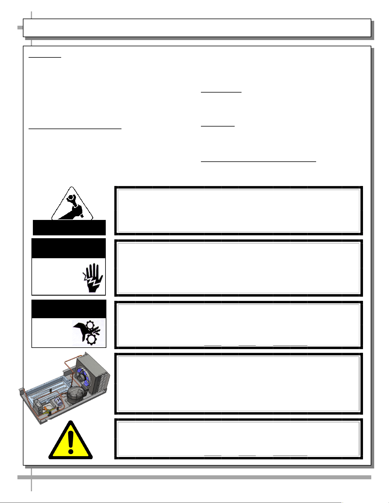
WARNINGS
• This page contains important warnings to prevent injury
or death.
• Please read carefully!
PRECAUTIONS and WIRING DIAGRAMS
• See next page for PRECAUTIONS and WIRING
DIAGRAM information.
WARNING
Hazardous moving parts. Do not operate unit with covers removed.
Fan blades may be exposed when deck panel is removed.
Disconnect power before removing deck panel.
WARNING
Risk of electric shock. Disconnect power before servicing unit.
CAUTION! More than one source of electrical supply is
employed with units that have separate circuits.
Disconnect ALL ELECTRICAL SOURCES before servicing.
WARNING
ELECTRICAL
HAZARD
WARNING
KEEP
HANDS
CLEAR
COMPLIANCE
This equipment MUST be installed in compliance with all applicable
NEC, federal, state and local electrical and plumbing codes.
OVERVIEW / TYPE / COMPLIANCE / WARNINGS / PRECAUTIONS / WIRING / PLUGS - PAGE 1 of 2
ATTENTION
CONTRACTORS
WARNING: This product can expose you to chemicals, including
Urethane (Ethyl Carbamate), which are known to the state of
California to cause cancer and birth defects or other reproductive
harm. For more information go to P65Warnings.ca.gov.
CAUTION! CHECK CONDENSATE PAN, ITS POSITION & PLUG!
Water on flooring can cause extensive damage!
• Before powering up case, check that condensate pan is positioned
directly under case’s condensate drain.
• Before powering up case, check that condensate pan’s electrical plug is SE-
CURELY connected to condensate system’s receptacle.
• If wicking material is used in condensate pan, check that it is secure.
4
OVERVIEW / TYPE / COMPLIANCE / WARNINGS / PRECAUTIONS / WIRING / PLUGS - PAGE 2 of 2
PRECAUTIONS
• Following are important precautions to prevent
damage to unit or merchandise.
• Please read carefully!
• See previous page for specifics on OVERVIEW,
TYPE, COMPLIANCE and WARNINGS.
WIRING DIAGRAM
• Each case has its own wiring diagram folded and in its
own packet.
• Wiring diagram placement may vary; it may be placed
near ballast box, field wiring box, raceway cover, or
other related location.
REFRIGERANT DISCLOSURE STATEMENT
• This equipment is prohibited from use in California
with any refrigerants on the “List of Prohibited
Substances” for that specific end-use, in accordance
with California Code of Regulations, title 17, section
95374.
• This disclosure statement has been reviewed and
approved by Structural Concepts and Structural
Concepts attests, under penalty of perjury, that these
statements are true and accurate.
WIRING DIAGRAM FORMAT & LOCATION
• Each case has its own wiring diagram folded and in its own packet.
• Wiring diagram placement may vary; it may be placed near ballast
box, field wiring box, raceway cover, or other related location.
CAUTION! GFCI BREAKER USE REQUIREMENT
If N.E.C. (National Electric Code) or your local code
requires GFCI (Ground Fault Circuit Interrupter) protection,
you MUST use a GFCI breaker in lieu of a GFCI receptacle.
CAUTION! DO NOT RELY ON THERMOMETERS OR
THERMOSTATS FOR PRODUCT (FOOD) TEMPERATURES.
• Thermometers & thermostats reflect air temperatures ONLY.
• For ACTUAL product (food) temperatures, use a calibrated food
probe thermometers ONLY.
• For accurate readings, DO NOT use infrared food thermometers.
CAUTION! ADVERSE CONDITIONS / SPACING ISSUES
• Performance issues caused by adverse conditions are NOT warranted.
• To prevent damage to end panels due to condensation, apply industrial grade
silicone sealant and tightly join to opposite end panels. When not adjoining
cases, keep end panels at least 6” away from walls and structures. Rear
panels must also be kept at least 6” from walls and structures.
• Case must not be exposed to direct sunlight or any heat source.
• To maintain proper case temperature, keep case at least 15-feet from exterior
doors, overhead HVAC vents or any air curtain disruption.
• Self-contained case clearance: 6” min. air intake / 6” min. air discharge.
CAUTION
5
SHIPPING BRACKETS / CASE REMOVAL FROM SKID - REMOTE UNITS
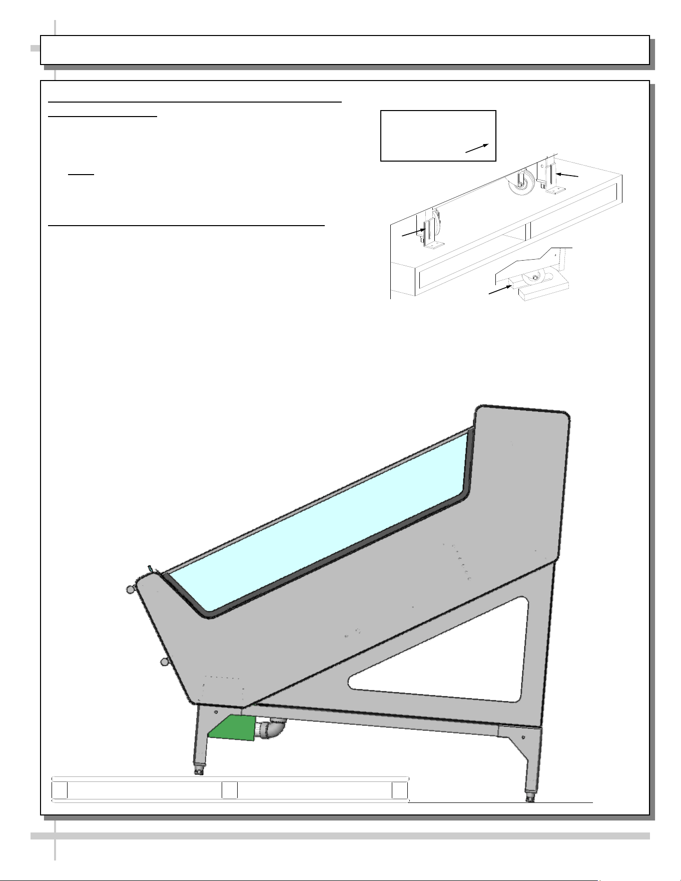
1. Removing Case Shipping Brackets That Are
Attached To Skid
• Remove screws holding case shipping brackets to
skid.
• Remove case shipping brackets from skid.
• Note: Shipping brackets will vary in size, shape,
material and location depending upon case type
and model. See illustration at right.
2. Remove Case From Skid - Remote Units
• To prevent damage, support case while sliding it
toward edge of skid.
• When case is at edge of skid, carefully lower to floor
so that two levelers (or one frame support rail) rests
on floor.
• Carefully slide skid out from under case.
• After case is off skid, place into position.
• See next page for instructions on self-contained unit
skid removal.
Various Types Of
Shipping Brackets
Shown With
6
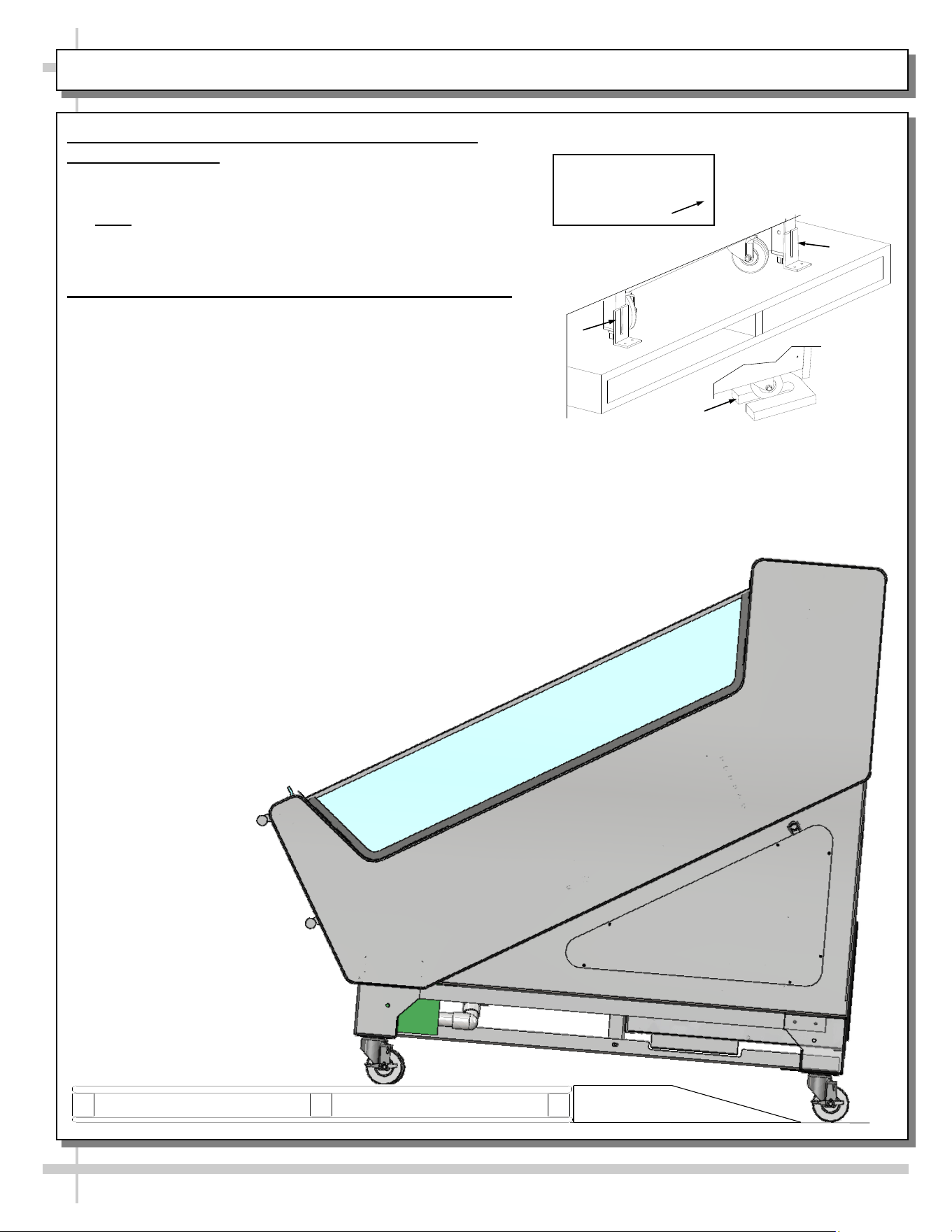
SHIPPING BRACKETS / CASE REMOVAL FROM SKID - SELF-CONTAINED UNITS
1. Removing Case Shipping Brackets That Are
Attached To Skid
• Remove screws holding case shipping brackets to skid.
• Remove case shipping brackets from skid.
• Note: Shipping brackets will vary in size, shape,
material and location depending upon case type and
model. See illustration at right.
2. Remove Case From Skid - Self-Contained Units
• To prevent damage, support case while sliding it
toward edge of skid.
• When case is at edge of skid, carefully slide down
ramp to floor so that two casters rest on floor.
• Carefully slide unit the rest of the way, down ramp and
onto the floor
• skid out from under case.
• After case is off skid, roll into position.
• Lock casters in place.
Various Types Of
Shipping Brackets
Shown With
7
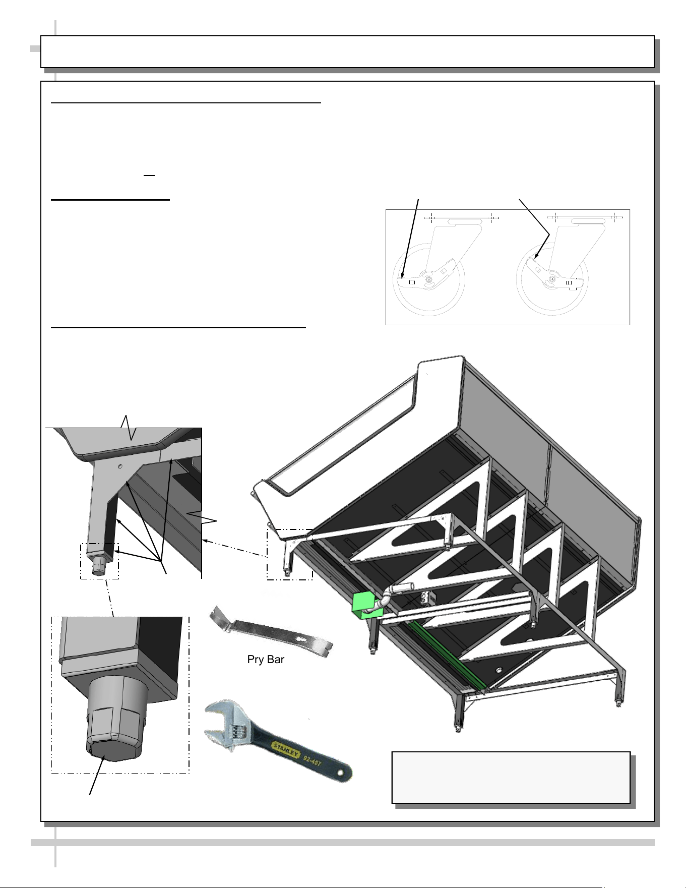
POSITIONING & ALIGNING / ADJUSTING LEVELERS / LOCKING CASTERS IN PLACE
• To unlock casters (from the locked position),
press down on the RAISED caster lever (as
shown in illustration below).
• Casters are now in unlocked position.
Pry Bar
Leveler
Base
Frame
Adjustable
Wrench
Illustration Shown Reflects Remote Unit Only.
It May Not Exactly Reflect Every Feature or
Option of Your Particular Case.
Casters
Locked
Casters
Unlocked
1. Position & Align Case Alongside Others
• Before adjusting levelers, make certain that the
case is in proper position and, if required, aligned
with adjoining case.
• This may require the repositioning of case you
are installing or the already positioned case.
2. Adjust Levelers
• After case is in position, adjust case so it is level
and plumb.
• Use adjustable wrench (and/or a pry bar) to
adjust leveler.
• Do not use pry bar on end panel. It may chip.
• Use pry bar ONLY on base frame to avoid
damaging case.
3. Caster Locking / Unlocking Operation
• To lock casters (from the unlocked position),
press down on each RAISED caster lever (as
shown top-right). Casters are now locked.
8
Note: Any Revisions Made To
This Sheet Must Also Be Made
To SCC P/N 21-12071.
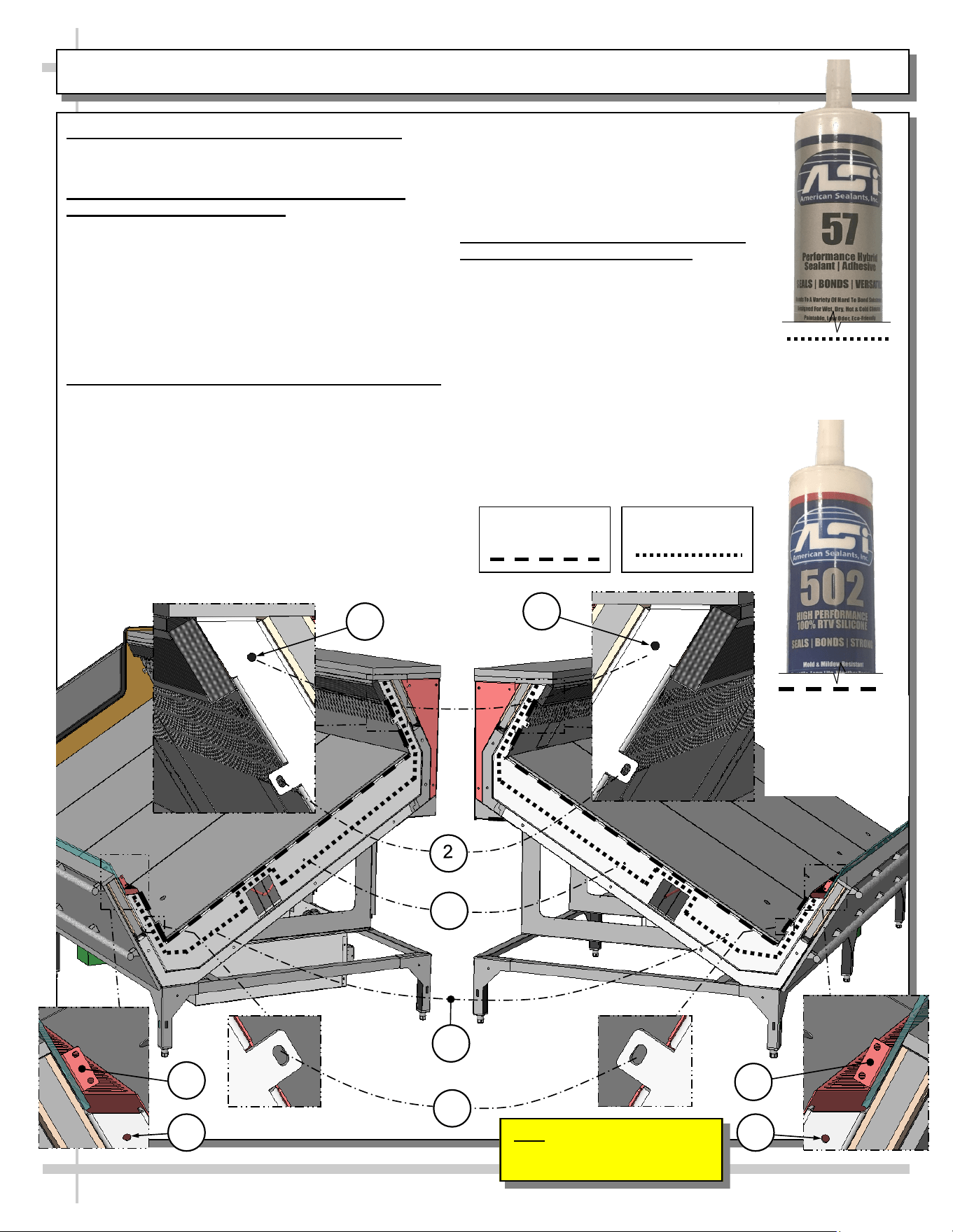
Adjoinment - Urethane/Silicone Application
>> Warranty is void if improper urethane/sealant is used.
>> Lay generous beads of urethane/sealant as specified.
A. Prior To Adjoinment - Apply Industrial Grade
Urethane at Center of Uprights
• Apply a generous bead (approximately ø3/8”) of
industrial grade urethane at center of uprights
(not-visible to the naked eye).
• Proper urethane application prevents refrigerated air
from escaping between cases (causing condensation
and reducing refrigeration efficiency) as well as
preventing insects from entering case.
• See illustration below.
B. Adjoining Cases - Using Nuts, Bolts and Washers
• Use appropriately sized nuts, bolts and washers for
each hole.
#1 - Holes are accessible by removing honeycomb air
diffuser.
#2 - Holes are accessible at tabs just below honeycomb
air diffuser.
#3 - Holes are accessible at underside of decking. Deck-
ing must be removed to attach bolts/nuts.
#4 - Holes are accessible at tabs just below air intake
grilles.
#5 - Holes are accessible by reaching into opening just
below air intake grilles.
#6 - Holes are accessible at tabs just above air
intake grilles.
• Tighten nuts securely (be careful to NOT
over-tighten)!
• See illustration below.
C. After Adjoinment - Apply Food Grade
Silicone Sealant To Inner Seams
• After all nuts, bolts and washers are
securely attached to case, apply a
generous bead of food grade silicone
sealant to inner seams.
• Decking must be removed to apply sealant
to certain inner seam areas.
• When properly applied, this food grade
silicone sealant will prevent water from
seeping between cases (into the case or
to the floor) as well as crumbs or other
residue from entering between case
seams.
ADJOINING CASES - MODEL FSIB8R SHOWN FOR ILLUSTRATIVE PURPOSES ONLY
Industrial Grade
Urethane Adhesive
(For Refrigeration
Bead Applications)
Silver, Black or Clear
Silicone Sealant
Conforming To NSF/
ANSI 51 Specs
(For Sanitation
Bead Applications)
1
Inner Silicone
Sanitation Bead
Refrigeration
Urethane Bead
1
3
3
4
5 5
6
6
START-UP / THERMOMETER / DISCHARGE AIR PROBES
9
1. Start-Up
• When case is properly field wired, it will start
operating.
• Supply power will start evaporator coil fans and
the compressor motor.
• From the front of the case, raise the deck pans
and check to see that the evaporator coil fans are
all functioning properly (see next page).
• When the case is in a start up mode (or has been
idle for a long period of time), the unit will require
approximately 30 minutes runtime in order to pull
down temperature.
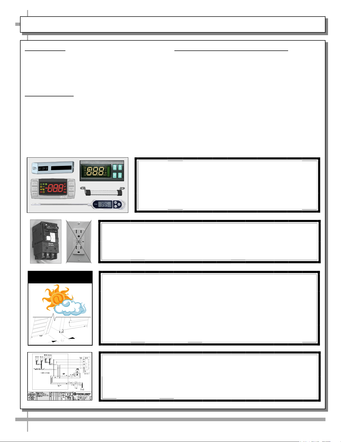
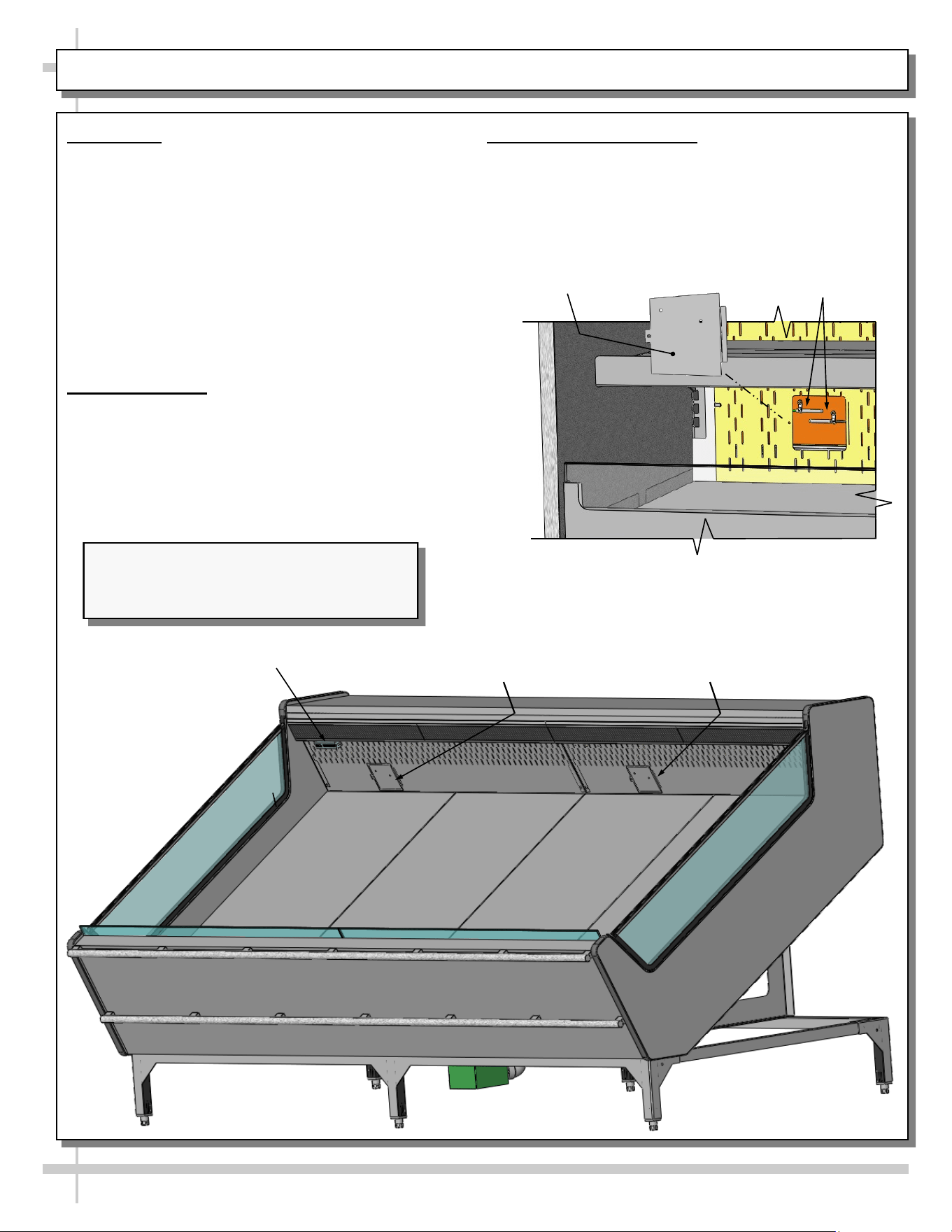
2. Thermometer
• Thermometer is located at rear plenum for
monitoring warmest air temperature.
• Probe must be used to determine actual product
temperature.
• See illustration below.
3. Discharge Air Probes
• Remove cover to access discharge air probes.
• General illustration of similar model shown below.
• Your model may differ in layout.
Thermometer
Discharge Air
Probe Location
(Behind Plate)
Discharge Air
Probes
Discharge Air
Probe Cover
Discharge Air
Probe Location
(Behind Plate)
--- Discharge Air Probes - Sample Layout ---
Illustration Shown Reflects Remote Unit Only.
It May Not Exactly Reflect Every Feature or
Option of Your Particular Case.
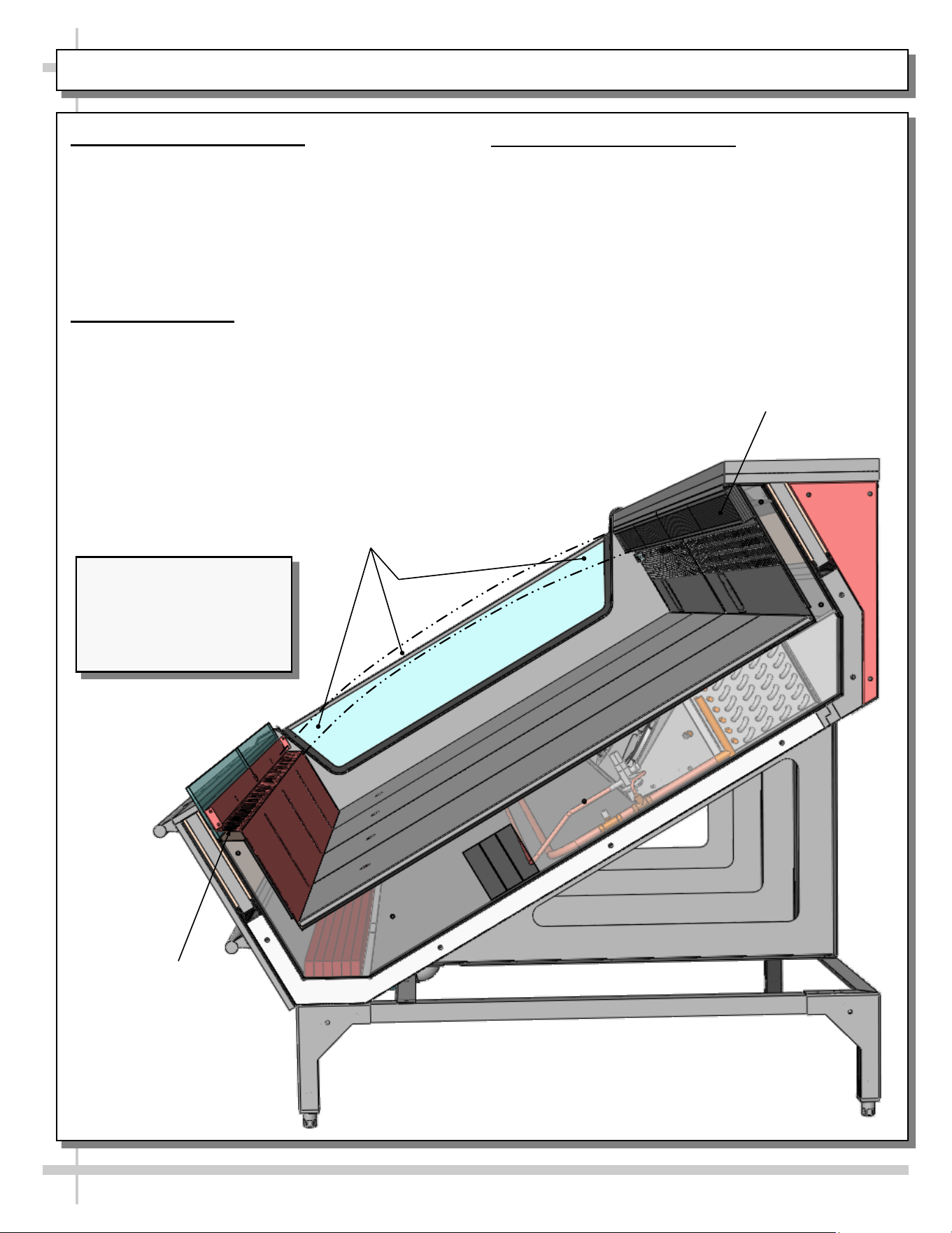
HONEYCOMB AIR DIFFUSER / AIR RETURN DUCT / REFRIGERATED AIRFLOW PATH
10
1. Honeycomb Air Diffuser
• Honeycomb air diffuser must remain
unobstructed at all times.
• Blockage of air discharge can result in poor
operating temperatures.
• See PREVENTIVE MAINTENANCE -
HONEYCOMB AIR DIFFUSERS section in this
manual for additional honeycomb information.
2. Air Return Duct
• Air return ducts must be open and free of
obstruction at all times.
• Blockage of air return duct can result in poor
operating temperatures.
3. Refrigerated Airflow Path
• Refrigerated airflow from honeycomb air diffuser
to air return duct passes over product.
• Caution! DO NOT STACK PRODUCT to height
that will impede this airflow path!
• Doing so will prevent case from keeping product
at proper temperature.
Honeycomb Air Diffusers.
Do Not Block These
Areas With Product
Refrigerated Airflow
Path. Do Not Block This
Area With Product.
Air Return Duct.
Do Not Block This
Area With Product
Illustration Shown Reflects
Remote Unit Only. It May
Not Exactly Reflect Every
Feature or Option of Your
Particular Case.
11
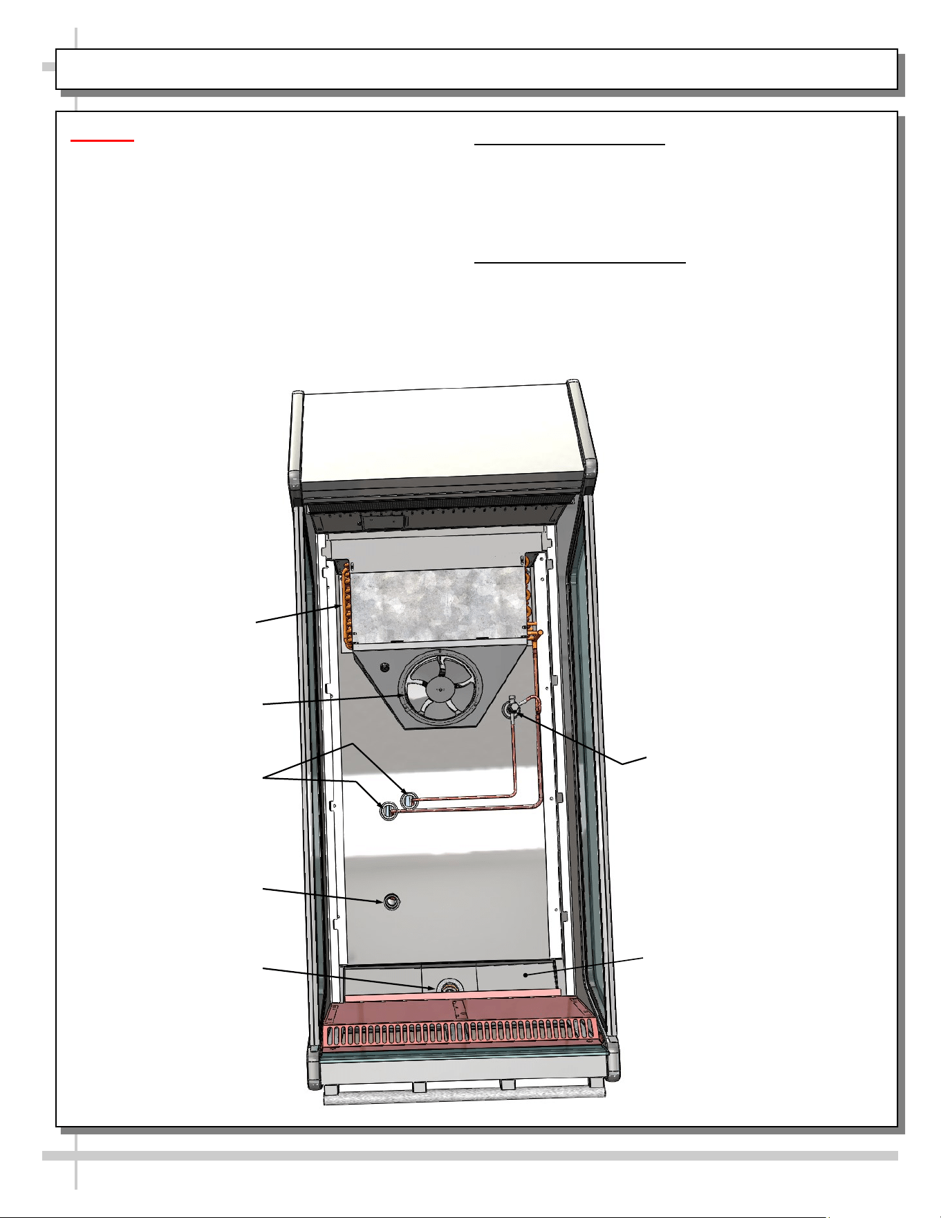
EVAPORATOR AREA: DECK PAN REMOVAL / REFRIGERANT COMPONENTS FOR FSIB8R ONLY
Caution! Hazardous moving parts.
• Authorized service personnel ONLY should
access this area.
• Do not operate unit with covers removed.
• Fan blades may be exposed when deck panel
is removed.
• Disconnect power before removing deck
panel.
1. Deck Pan Removal
• Illustration below shows merchandiser after deck
pans have been removed.
• Store in safe place out of foot traffic while
removed from case.
2. Components / Routes
• Illustration below shows components such as
refrigeration lines, TXV, drain, drain trough,
motors and fans, etc.
• Illustration below shows general layout.
Refrigeration Lines
(Routed To Remote
Refrigeration Supply)
Refrigeration Line
Pass-Throughs
Drain
TXV
Drain
Trough
Evaporator Fan
Shroud (With
Evaporator Coils
at Underside)
Evaporator
Motors/Fans
Wiring Route
Coil
12
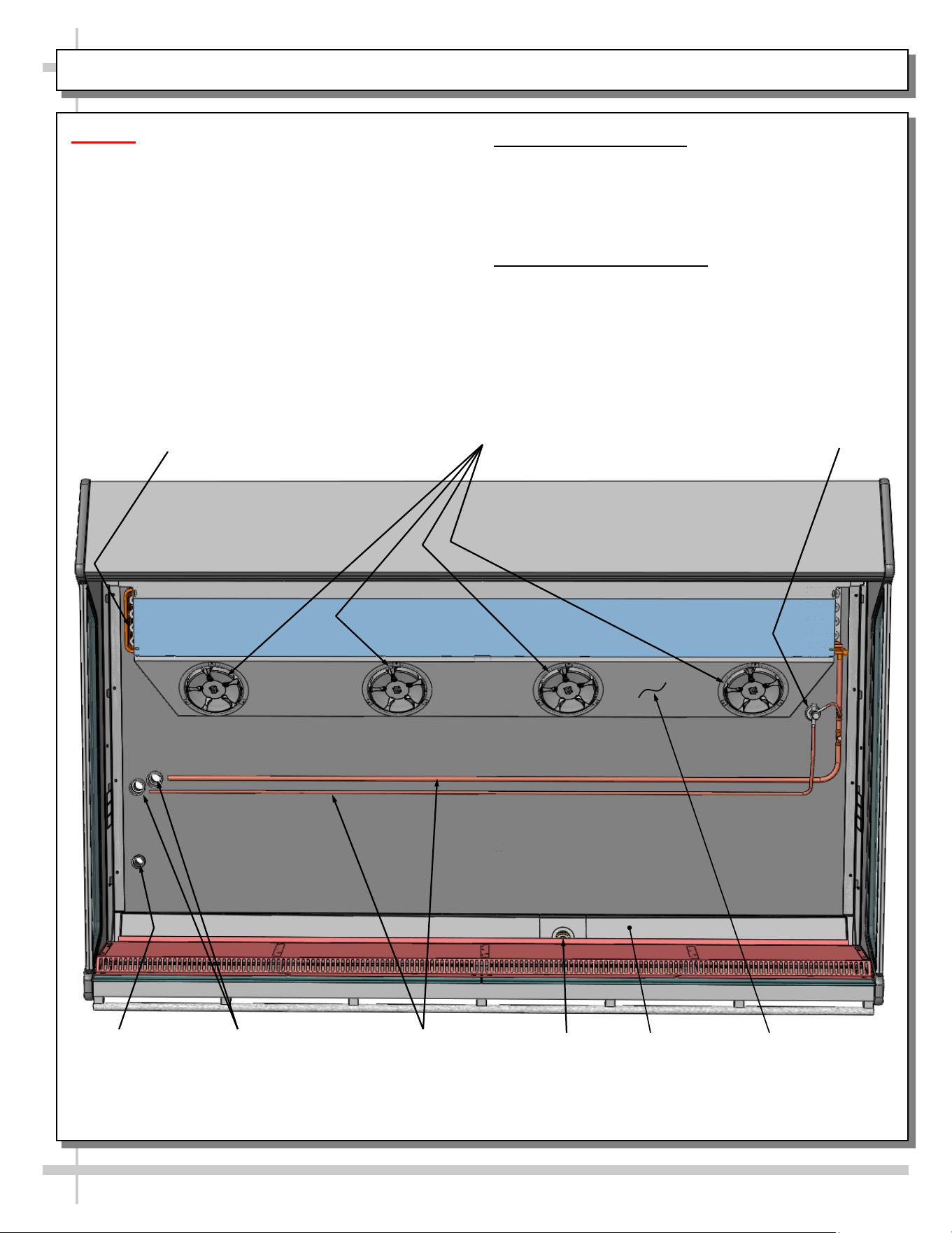
EVAPORATOR AREA: DECK PAN REMOVAL / REFRIG. COMPONENTS FOR FSIB2R ONLY
Caution! Hazardous moving parts.
• Authorized service personnel ONLY should
access this area.
• Do not operate unit with covers removed.
• Fan blades may be exposed when deck
panel is removed.
• Disconnect power before removing deck
panel.
1. Deck Pan Removal
• Illustration below shows merchandiser after deck
pan has been removed.
• Store in safe place out of foot traffic while
removed from case.
2. Components / Routes
• Illustration below shows components such as
refrigeration lines, TXV, drain, drain trough,
motors and fans, etc.
• Illustration below shows general layout.
Refrigeration Lines
(Routed To Remote
Refrigeration Supply)
Refrigeration Line
Pass-Throughs
Drain
TXV
Drain Trough
Evaporator
Motor/Fan
Wiring Route
Coil
13
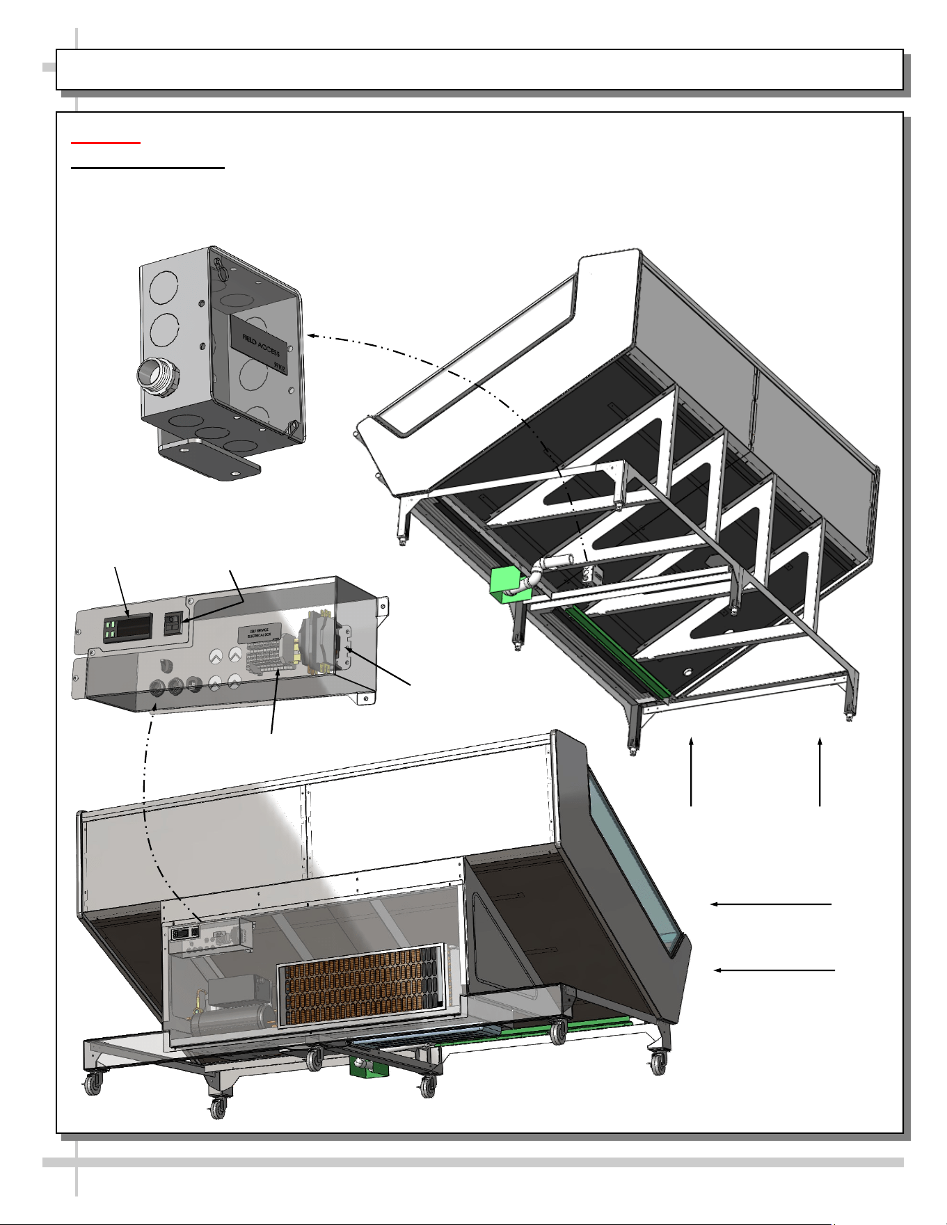
ELECTRICAL LAYOUT: MODEL FSIB8R REMOTE & SELF-CONTAINED UNITS
Caution! Authorized service personnel ONLY should access this area.
Field Access Box
• Illustration below shows field access box for both remote and self-contained units.
• Caution! Authorized service personnel ONLY should access this area.
Contactor
Terminal Block
Thermostat
Main Power
Switch
Rear View of
Self-Contained
Merchandiser
Underside View
of Remote
Merchandiser
14
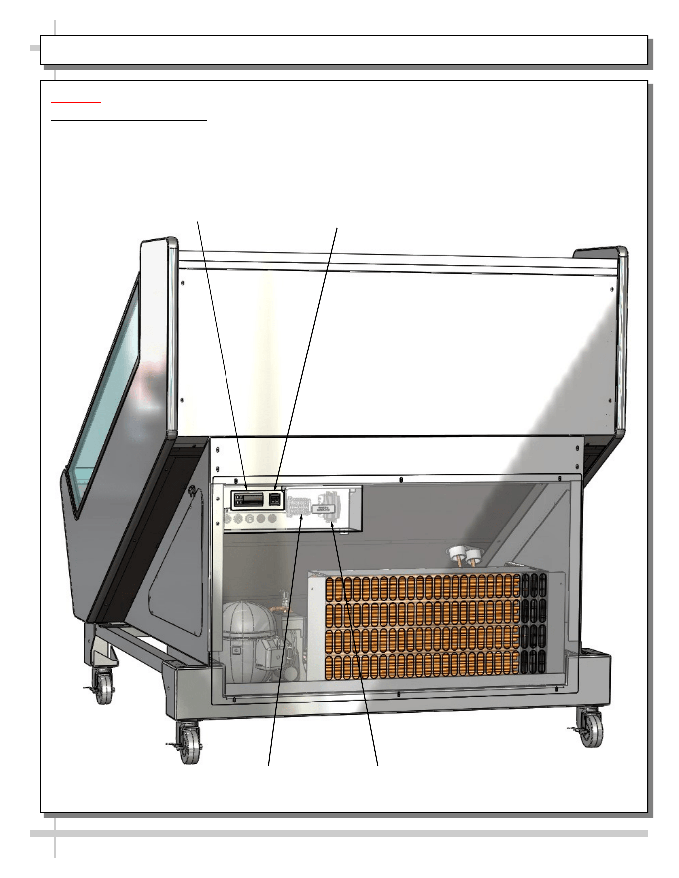
ELECTRICAL LAYOUT: MODEL FSIB4R SELF-CONTAINED UNITS ONLY
Caution! Authorized service personnel ONLY should access this area.
Self-Service Access Box
• Illustration below shows field access box for both remote and self-contained units.
• Caution! Authorized service personnel ONLY should access this area.
Contactor
Terminal Block
Thermostat
Main Power Switch
15
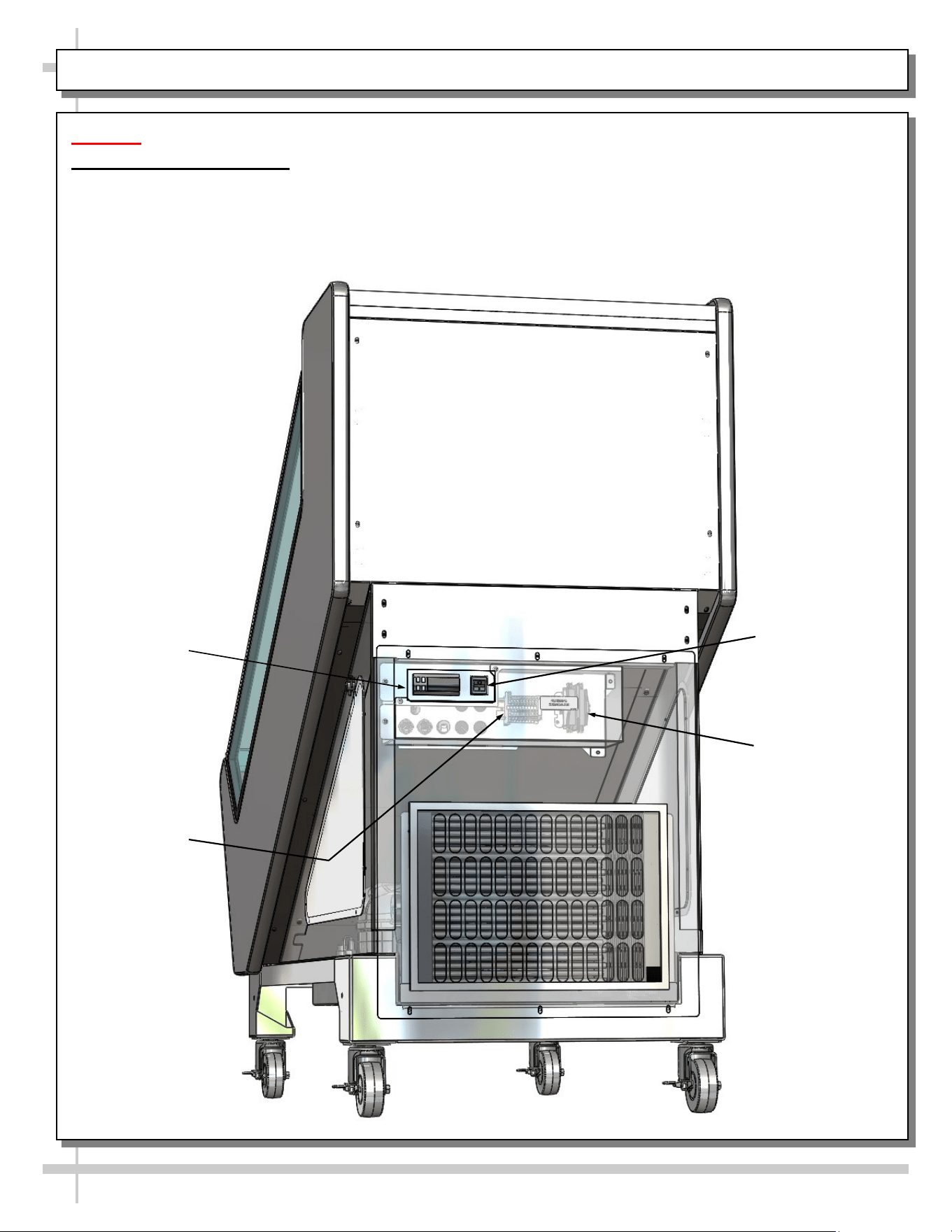
ELECTRICAL LAYOUT: MODEL FSIB2R SELF-CONTAINED UNITS ONLY
Caution! Authorized service personnel ONLY should access this area.
Self-Service Access Box
• Illustration below shows field access box for both remote and self-contained units.
• Caution! Authorized service personnel ONLY should access this area.
Contactor
Terminal Block
Thermostat
Main Power
Switch
16
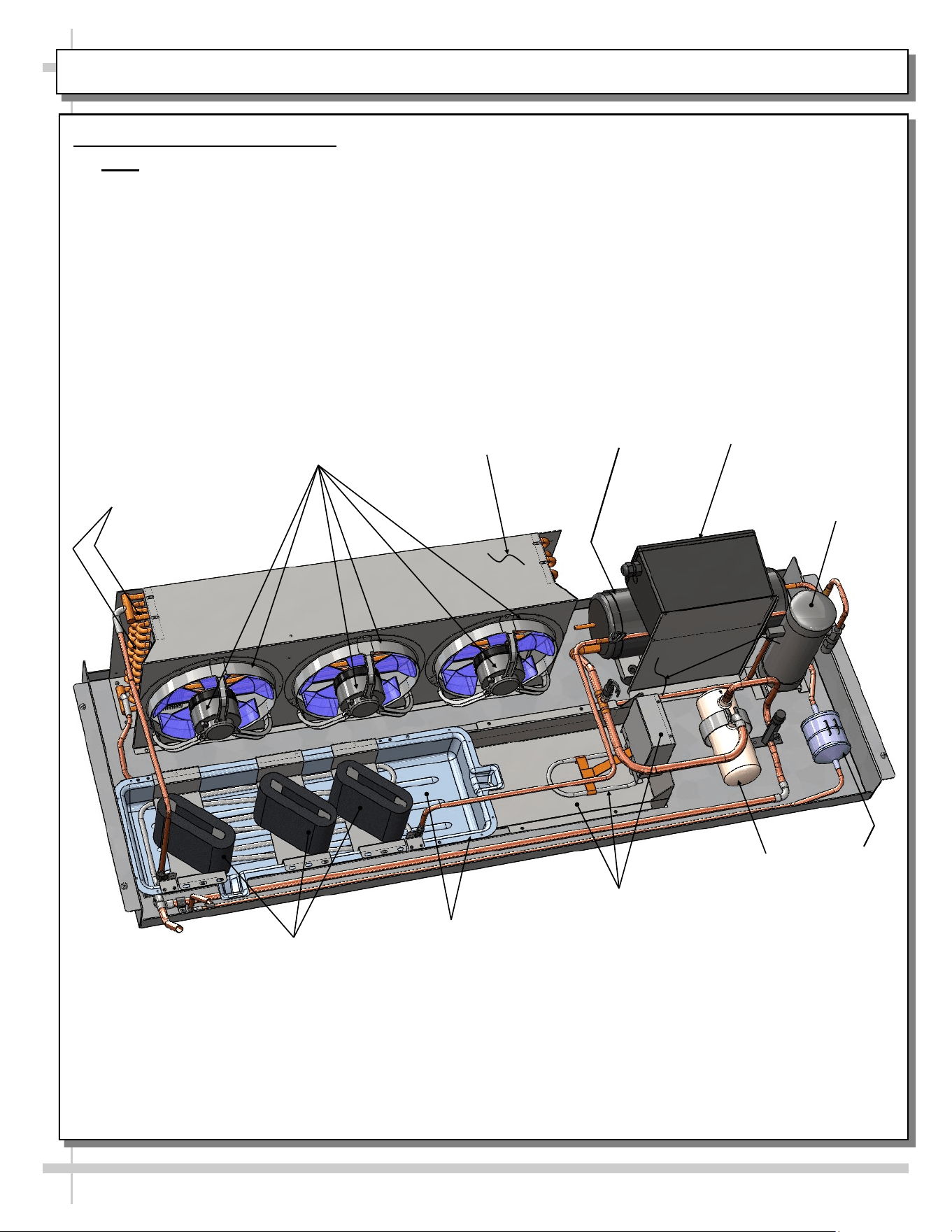
CONDENSER PACKAGE LAYOUT: MODEL FSIB8R SELF-CONTAINED UNITS ONLY
Refrigeration
U-Tubes
Filter Dryer
Condenser Coil
Housing
Condenser Coil Fan,
Fan Housing & Motor
Overflow Pan /
Electrical Coil Unit
Wicking Material
(Optional)
Refrigeration Package Layout
• Note: Due to design variables, refrigeration package component layout can vary in location.
• Illustration below may not reflect every feature or option of your particular case.
Hot Gas Loop
Condensate Pan
Compressor
Accumulator
Receiver
Compressor
Electrical Box
17
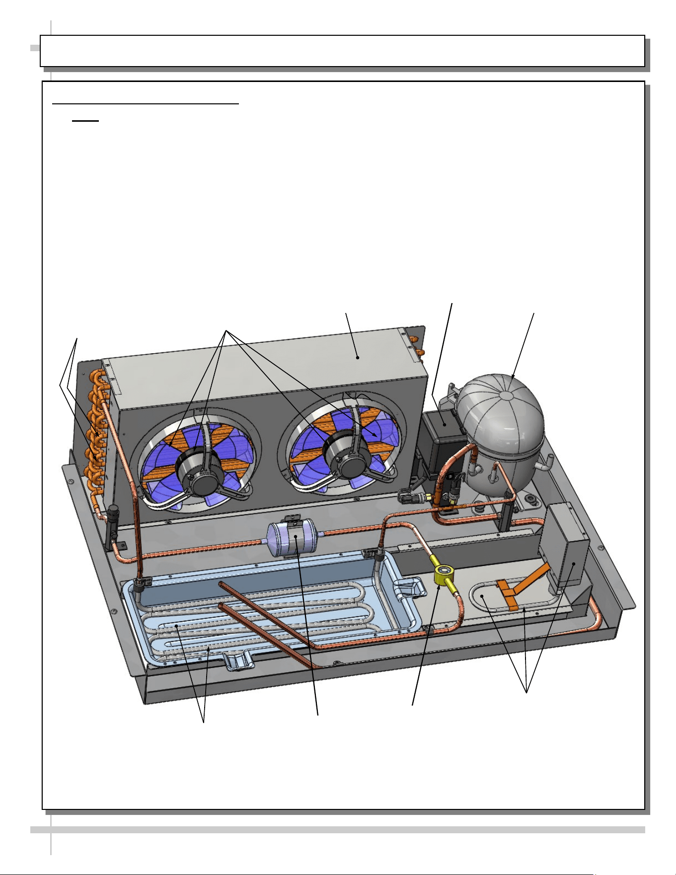
CONDENSER PACKAGE LAYOUT: MODEL FSIB4R SELF-CONTAINED UNITS ONLY
Filter Dryer
Condenser Coil
Housing
Condenser Coil Fan,
Fan Housing & Motor
Overflow Pan /
Electrical Coil Unit
Refrigeration Package Layout
• Note: Due to design variables, refrigeration package component layout can vary in location.
• Illustration below may not reflect every feature or option of your particular case.
Hot Gas Loop
Condensate Pan
Compressor
Sight Glass
Refrigeration
U-Tubes
Compressor
Electrical Box
18
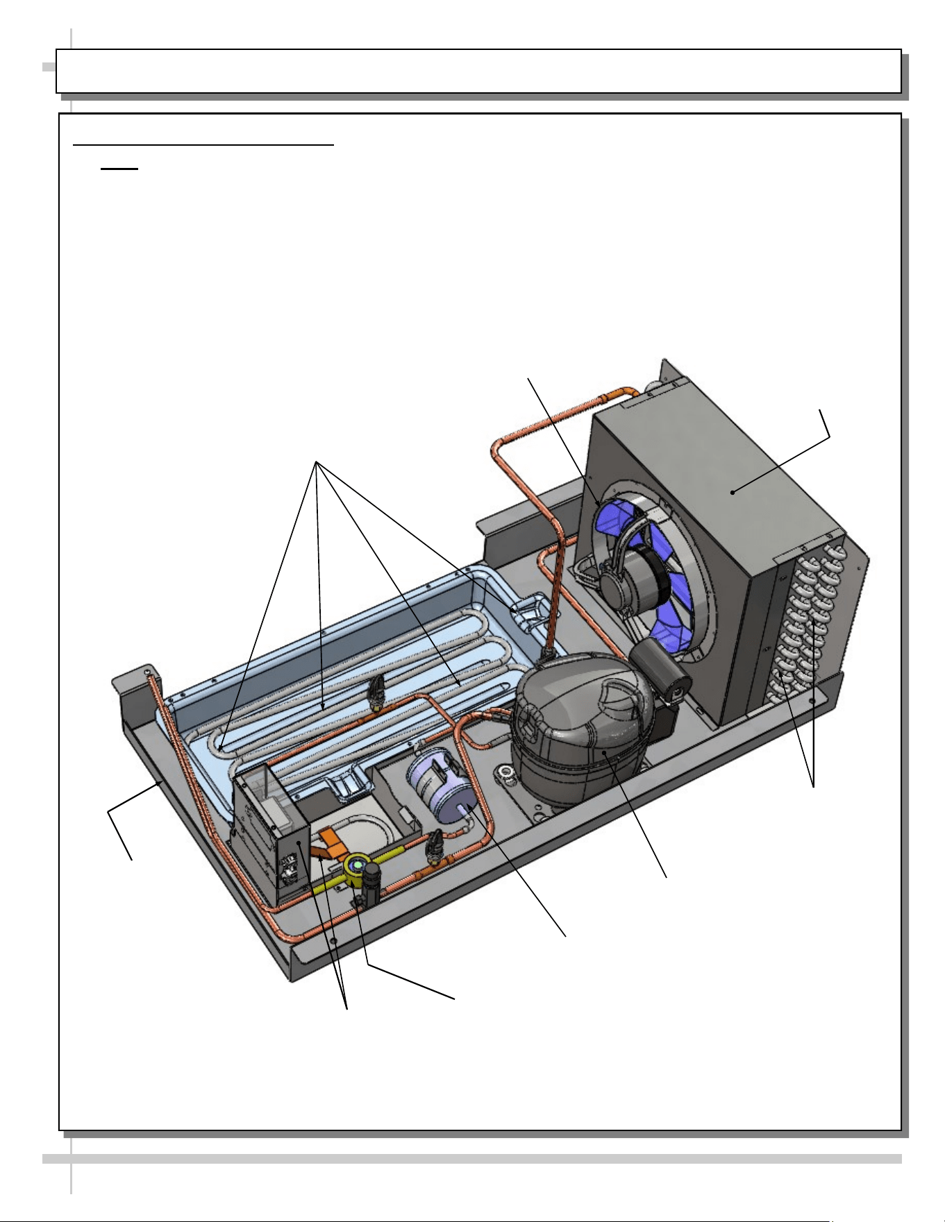
CONDENSER PACKAGE LAYOUT: MODEL FSIB2R SELF-CONTAINED UNITS ONLY
Refrigeration
U-Tubes
Filter Dryer
Condenser Coil
Housing
Condenser Coil Fan,
Fan Housing & Motor
Overflow Pan /
Electrical Coil Unit
Refrigeration Package Layout
• Note: Due to design variables, refrigeration package component layout can vary in location.
• Illustration below may not reflect every feature or option of your particular case.
Hot Gas Loop
Condensate Pan
Compressor
Sight Glass
Condensate Pan
19
GENERAL CLEANING SCHEDULE - TO BE PERFORMED BY STORE PERSONNEL (EXTERIOR)
FREQ. INSTRUCTIONS
Daily Acrylic: Acrylic sneeze guard must be cleaned with a mild soap and water solution and a soft
cloth. Caution! Never use ammonia-based cleaners on acrylic. Incorrect cleaning
agents or abrasive cleaning cloths cause surface to ‘cloud’ over time.
Daily Sides, Top, Rear Plenum, etc.: Clean with a warm soap and water solution and soft cloth.
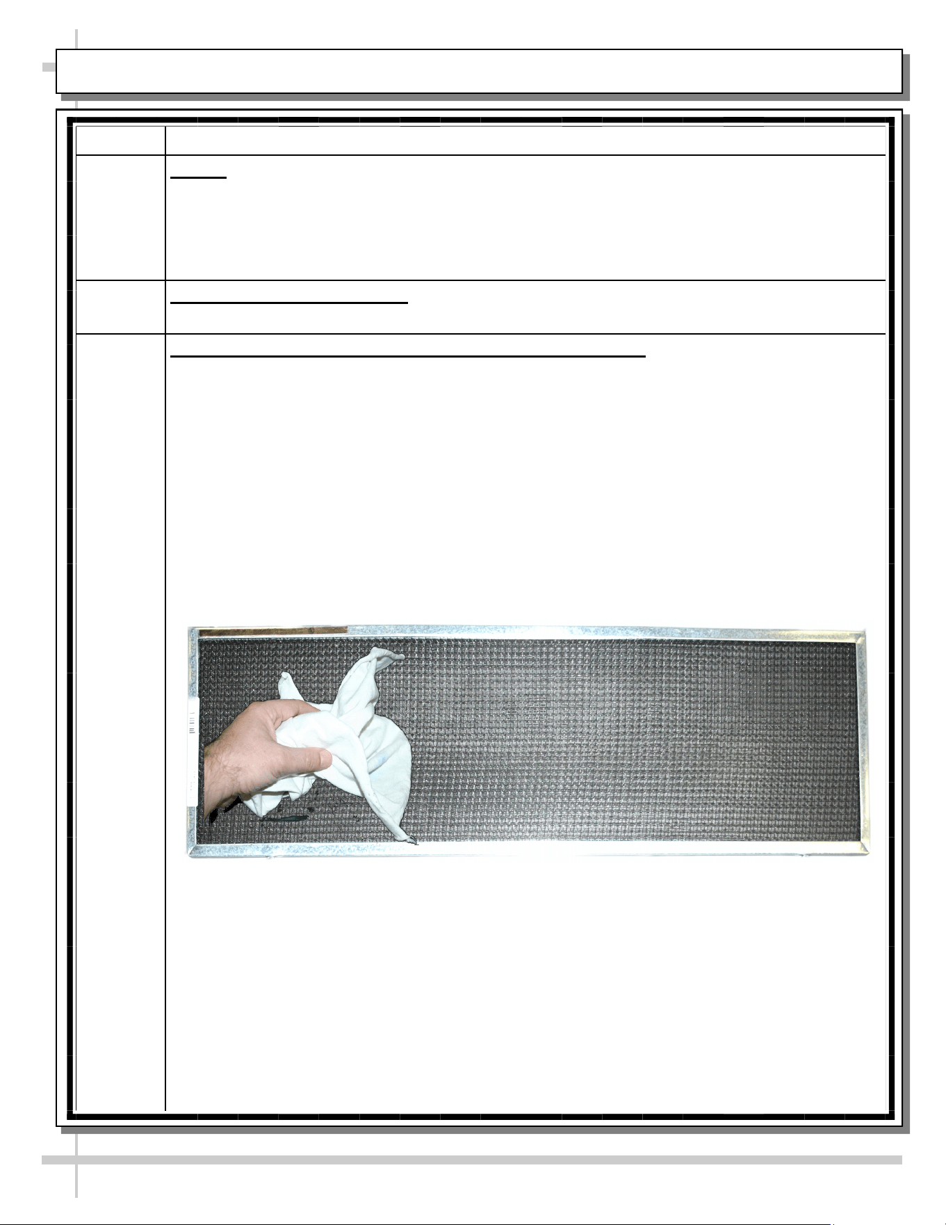
Weekly Magnetic Condenser Coil Filter (Self-Contained Units Only):
• This filter helps prevent dust particles from entering condenser coil.
• It is accessible at case rear.
• Clean magnetic condenser coil filter by following either of these steps:
1. As magnetic condenser coil filter is dishwasher safe, remove from case (no screw
removal required) and use a rag or soft-bristled brush to wipe off excess dust particles
from filter. Run in normal dishwasher cycle. Remove from dishwasher. Dry with soft
cloth or paper towel. Return to case.
2. If not using dishwasher, remove magnetic condenser coil filter from case. Use a rag or
soft-bristled brush to wipe off excess dust particles from filter. Submerse in warm,
soapy water. Use soft-bristled brush to remove dust, dirt, grease and grime that may
collect on filter. Rinse thoroughly.
3. Dry with soft cloth or paper towel (as shown below) or allow to air dry. Replace.
GENERAL CLEANING SCHEDULE - TO BE PERFORMED BY STORE PERSONNEL (INTERIOR)
20
FREQ. INSTRUCTIONS
Weekly Decks:
• Clean with a warm soap and water solution and soft cloth.
• If necessary, entirely remove from case, and submersed in warm, soapy water.
Use soft-bristled brush to remove food particles, dust, grease or grime. Rinse thoroughly.
Dry. Return to case.
GENERAL CLEANING SCHEDULE - TO BE PERFORMED BY TRAINED SERVICE PROVIDERS ONLY
21
FREQ. INSTRUCTIONS
Weekly Drains: Keep drains clean and free of debris which could clog the drain and rob the case of
needed refrigeration. After removing decks, vacuum tub under deck or flush with water if
necessary.
Monthly Evaporator Fan Shroud Area (Under Decking): Caution! Due to rotating fans in area,
turn off case and disconnect power (or remove plug from wall outlet) before beginning.
1) Turn off power.
2) Remove product from case.
3) Remove decking from case.
4) Wipe down fan shroud, evaporator fan blades, TXV, refrigeration lines, tub, drain trough
and drain with cloth dipped in warm soap and water solution.
5) Return decking to case.
6) Return product to case.
7) Restore power to case.
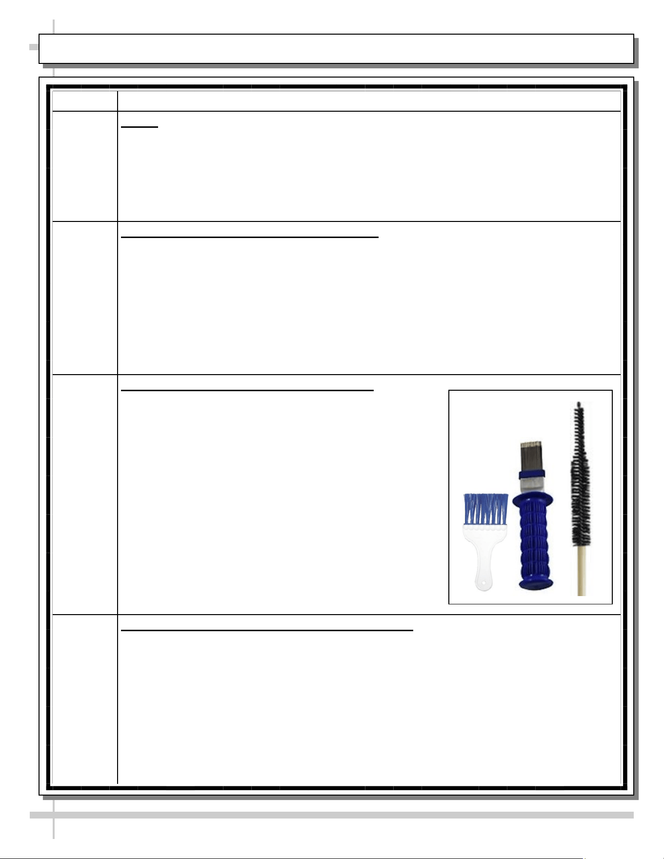
Quarterly Condensing Coil (Self-Contained Units Only):
• Remove magnetic condenser coil filter.
• Remove rear panel (by lifting it up and off).
• Condenser coil brush may be used to dislodge dust, dirt
and debris from condenser coil.
• Slide condensing package out from underside of case
(taking care to NOT slide out too far and damage hoses).
• Use air pressure or industrial strength vacuum; clean dust
and dirt that may collect on condenser coil.
DO NOT allow dust to become airborne. Use wet cloths
or paper towels to cover area where dust will fly when air
pressure is applied.
• Caution! Coil fins are sharp. Handle with care!
• Replace lower panel in reverse order it was removed.
• See sample condenser coil cleaning brushes at right.
Quarterly Honeycomb Air Diffuser (Service Technicians Only):
• See next page in this operating manual for cleaning specifics.
22
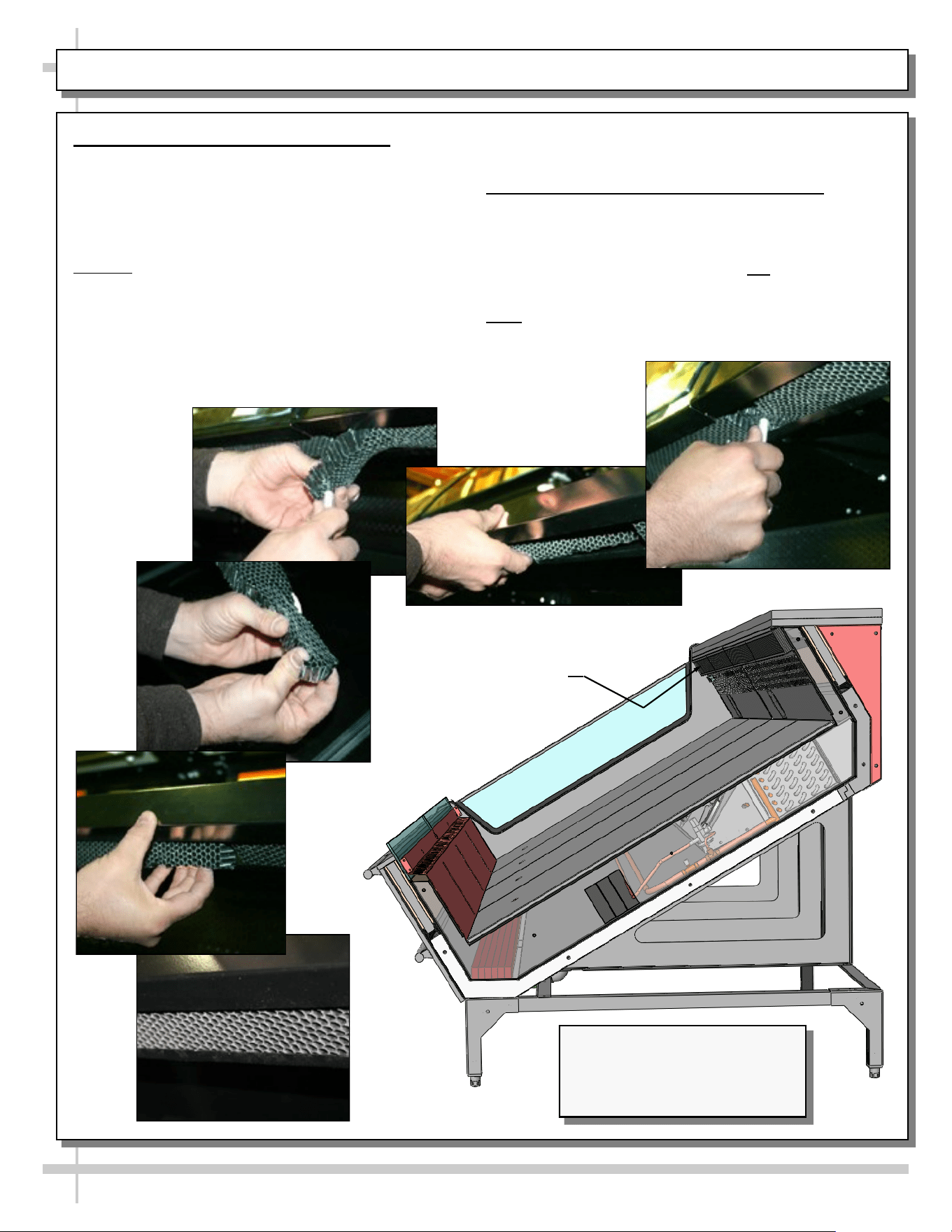
GENERAL CLEANING SCHEDULE - HONEYCOMB AIR DIFFUSERS (SERVICE TECHNICIANS ONLY)
1. Honeycomb Air Diffuser Removal
• Honeycomb air diffuser cleaning is to be
performed quarterly.
A. Wedge a non-metallic device of suitable strength
(such as a ballpoint pen) between the honeycomb
and the end panel.
Caution! Use care not to dislodge the heating wire
(that prevents condensation on the lamp assembly).
B. Apply pressure to collapse the honeycomb to
allow it to be pulled out of honeycomb retainer.
C. Carefully pry downward and away from the
honeycomb retainer. Clean honeycomb with warm
water and soap solution. Submerse if necessary.
C
D
F
Use brush to dislodge stubborn or sticky residue.
Dry by using vacuum’s blow mode (vs. suction mode).
2. Honeycomb Air Diffuser Installation
D. Squeeze honeycomb to allow it to fit into the
honeycomb retainer.
E. Carefully slide honeycomb into place.
F. Adjust honeycomb so that it fits flat against
retainer. It must not be wavy or out of position.
Note: For honeycomb air diffusers in other locations,
these same general instructions apply.
E
B
Honeycomb
Air Diffuser
A
Illustration Shown Reflects
Remote Unit Only. It May Not
Exactly Reflect Every Feature or
Option of Your Particular Case.
23
TROUBLESHOOTING - TO BE PERFORMED BY TRAINED SERVICE PROVIDERS ONLY
CONDITION TROUBLESHOOTING
Case Not
Lining Up
See POSITIONING & ALIGNING / ADJUSTING LEVELERS / LOCKING CASTERS IN
PLACE section in this manual for instructions on properly aligning case (alongside other
cases) and adjusting levelers.
Water Is On
The Floor
Caution! Water on flooring can cause much damage! Until cause is determined (and
repaired), follow these procedures:
• Use wet-dry vacuum (or mop & bucket) to remove standing water.
• Use ‘catch pans’ for water to drain into. Swap out regularly until case has drained.
• When power to case is restored, condensate pan should function properly and water
will no longer overflow onto flooring.
• Note: See Drain, Hose and Bracket Placement Illustrations sheet in this manual for
views of different condensate systems used in display cases.
Check that the drain trap is free of debris.
Check that the drain hose is correctly positioned over condensate pan (or floor drain, for
remote units).
Check store conditions.
• To prevent condensation in NSF/ANSI Type I environments, maximum conditions are
to be 55% relative humidity / 75° Fahrenheit.
• For NSF/ANSI Type II environments, maximum conditions are to be 55% relative
humidity / 80° Fahrenheit.
• If you are unsure if your unit is classified as NSF/ANSI Type I or Type II, see tag next
to serial label on your case.
Check condensate pan float for proper operation (electric condensate trays).
Check that condensate pan is properly plugged in or connected.
Caution! Wicking material (if any) on your particular hot gas loop condensate tray may
be dirty or worn and need replacement.
• Slide condensate package out from under unit.
• After refrigeration system has been carefully slid out, replace wicking material with
new. If wicking material is not available, contact Structural Concepts. See toll-free
number at last page of this operating manual.
• See CONDENSER PACKAGE LAYOUT (SELF-CONTAINED UNITS ONLY) section
in manual for wicking material illustration.
24
TROUBLESHOOTING - TO BE PERFORMED BY TRAINED SERVICE PROVIDERS ONLY, CONTINUED
CONDITION TROUBLESHOOTING
Fan Emits Loud
Noise
Check that the case is aligned, level and plumb.
Check evaporator fans for cleanliness.
Unplug/power off fan motors. Check motor shaft for bearing wear.
Check that fan motors are securely mounted in brackets.
Verify that fan blades are securely mounted to fan motor.
Check that nothing is preventing blade rotation.
Check that the fan shroud is properly secured.
Fans Are Not
Working
Check that the MAIN power switch is on (self-contained units).
Check that fans are plugged in at the fan shroud.
Check for foreign material obstructing fan performance.
Check that fan blades freely rotate within fan shrouds.
Check that power is going to fans.
Check that fan wiring is connected to terminal blocks
25
TROUBLESHOOTING - TO BE PERFORMED BY TRAINED SERVICE PROVIDERS ONLY, CONTINUED
CONDITION TROUBLESHOOTING
Digital Control Display Is
Blank
Check that the MAIN power switch is on (self-contained units only).
Check the circuit breaker box for tripped circuits.
System Is Not Operating Check that the utility power is on.
Check that the MAIN power switch is on (self-contained units only).
Check the circuit breaker box for tripped circuits.
Control Display Is
Flashing
See your case’s thermostat label (near temperature controller) for your
model’s required settings.
Case Is Not Holding
Temperature
If a large amount of warm product was added to the case, it will take time for
the temperature to adjust. Unit needs product to be pre-chilled.
Temperature changes during defrost mode but will return to normal. Fourth
LED will indicate defrost cycle in progress.
Check that case is not in sun or near a heat or air-conditioning vent.
If case is located near outside doors, temperature fluctuation can hinder unit’s
ability to maintain temperature. See OVERVIEW / TYPE / COMPLIANCE /
WARNINGS / PRECAUTIONS / WIRING / PLUGS - PAGE 2 of 2 in
manual for adverse conditions/spacing issue parameters.
Check that condenser coil has been cleaned.
Check that magnetic air filter (attached to rear grille) has been cleaned.
See GENERAL CLEANING SCHEDULE - TO BE PERFORMED BY STORE
PERSONNEL) section in operating manual for instructions.
Check return air grilles for obstructions.
Check sight glass for flashing and/or low charge.
Check set point temperature; it may be adjusted too high.
Condensing Unit Is Not
Operating
Check that the power is turned on.
Determine if temperature controller settings are properly set. See your case’s
serial label for your model’s specified settings. See SERIAL LABEL
LOCATION & INFORMATION LISTED / TECH INFO & SERVICE section in
manual for label location, etc.
26
TROUBLESHOOTING - CONDENSING SYSTEM ( BY TRAINED SERVICE PROVIDERS ONLY)
CONDITION TROUBLESHOOTING
Head Pressure Too High Check that the condensing coil is not dirty or covered.
Check that condensing fans are working.
Check that refrigerant is not overcharged.
Perform sub-cooling check and verify that no contaminates are in system.
Check that liquid line filter dryer is not plugged.
Check that close-offs are intact (around condensing coil) and that air is not
recirculate.
Check that store ambient temperature isn’t above maximum allowed. See
OVERVIEW / TYPE / COMPLIANCE / WARNINGS / PRECAUTIONS /
WIRING / PLUGS section in this manual.
Head Pressure Too Low Check if sight glass is flashing or showing low charge.
Check that suction pressure isn’t too low.
Check that compressor reed valves aren’t bad. Look for high suction/low
head pressure. Perform pump-down.
27
TROUBLESHOOTING - EVAPORATOR SYSTEM (BY TRAINED SERVICE PROVIDERS ONLY)
CONDITION TROUBLESHOOTING
Low Suction Pressure Check if sight glass is flashing or showing low charge.
Check that expansion valve (TXV) isn’t restricted. Check element charge.
Check that liquid line or filter isn’t restricted. Check that refrigeration lines
and/or hoses are not kinked on either high or low sides.
Check that evaporator fan motors are working.
Check that superheat is between 6 °F to 8 °F.
Check that there is no air recirculation around evaporator coil.
Check that evaporator coil is not iced up.
High Suction Pressure Check for refrigerant overcharge.
Check that compressor reed valves aren’t bad. Look for high suction/low
head pressure. Perform pump down.
Check that the “cooling load” isn’t high. Product must be pre-chilled before
placing in refrigerated section of case.
Check that case is at least 15-feet from exterior doors, overhead HVAC
vents or any air curtain disruption.
Check that unit is not exposed to direct sunlight via windows or any other
heat source (ovens, fryers, etc.).
Check that superheat adjustment isn’t low.
Check TXV bulb installation
a. Poor thermal contact.
b. Warm location.
28
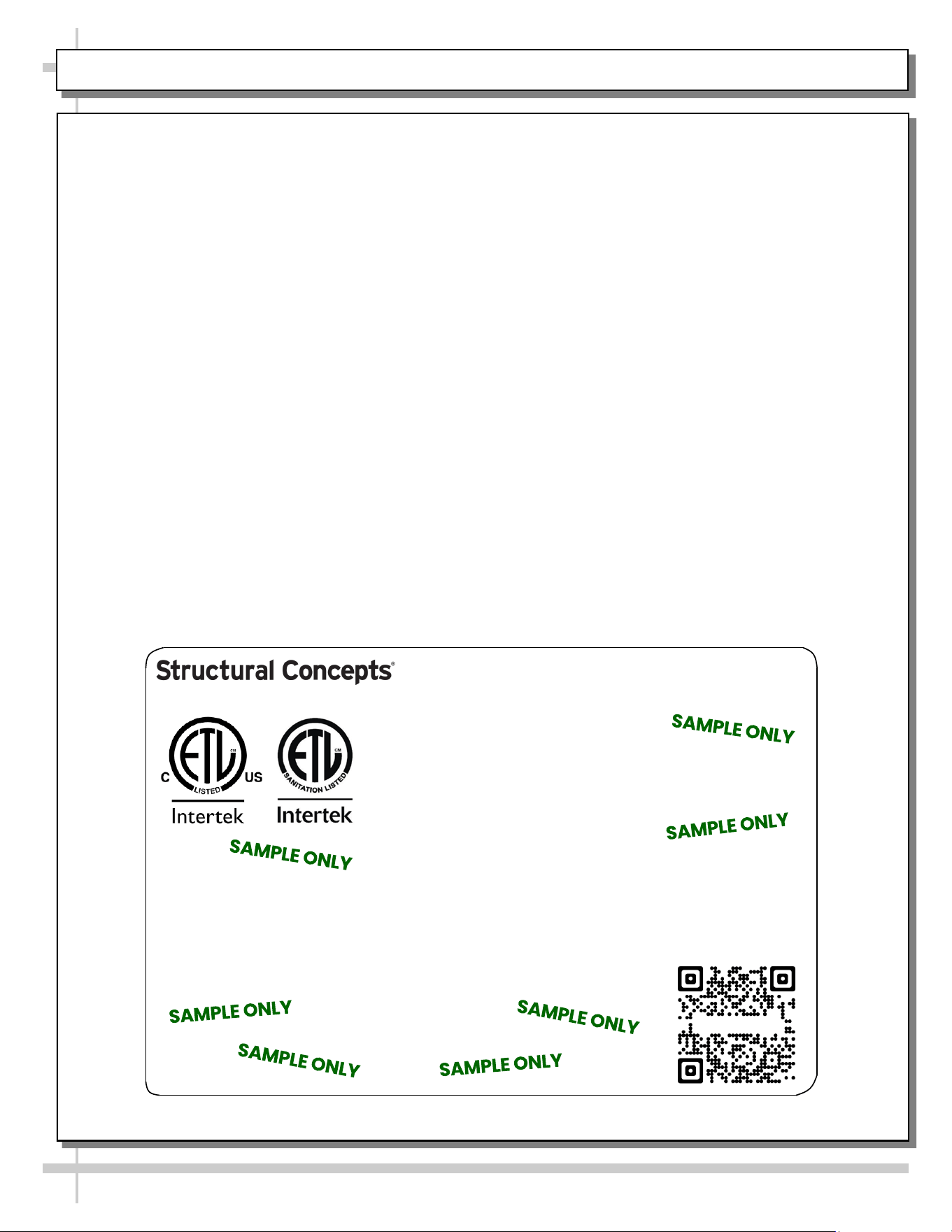
SERIAL LABEL LOCATION & INFO LISTED / TECH INFO & SERVICE / REFRIGERATED CASES ONLY
--- Sample Serial Label For Refrigerated Cases ---
MODEL NRS3648RXV-SAMPLE
SERIAL NO. 12345X30DZ098765
888 E. Porter Rd - Muskegon, MI 49441
3048256
Conforms to UL Std. 471
Conforms to NSF/ANSI Stds. 2 & 7
CERTIFIED TO CAN/CSA
STD C22.2 NO 120
ELECTRICAL RATING
REFRIGERANT
DESIGN PRESSURE
MINIMUM CIRCUIT AMPACITY
MAXIMUM OVERCURRENT
120/1/60 16 A
R513A AMOUNT 50 OZ
HIGH 186 LOW 88
20A
20A
Super Heat Temp 6-8 °F FOR PARTS AND SERVICE
Defrost 6 defrosts per day, 45 °F CALL 1-800-433-9490
Serial Label Location & Information Listed /
Technical Information & Service
• Serial labels are affixed at a wide range of places
(on the header, near thermostat, at case rear,
behind panels/toe-kicks, on electrical boxes, etc.).
• Serial labels contain electrical, temperature and
refrigeration information, as well as regulatory
standards to which the case conforms.
• Sample serial label is shown. A variety of models is
displayed on serial label for illustration purposes only.
Your case’s serial label will reflect only one model.
• For additional technical information and service, see
the TECHNICAL SERVICE page in this manual for
instructions on contacting Structural Concepts’
Technical Service Department.
Reveal
Harmony
Fusion
Impulse
Addenda
Blend
Grocerant
Oasis
Sample QR Code
SCAN FOR PRODUCT LITERATURE
SAMPLE ONLY
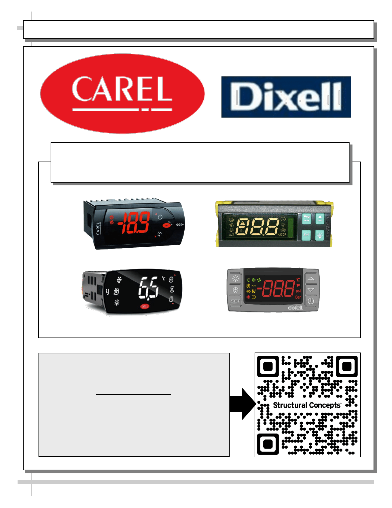
PROGRAMMABLE CONTROLLER (SELECT, CLICK ON OR SCAN QR CODE FOR INFORMATION)
29
Carel® iJF Platform
Carel® PJEZ Platform
Carel® ir33 Platform
Dixell® XM670K-XM679K Platform
To Access Information About The Programmable
Controller That Is Used On Your Case,
Follow These Instructions:
> If Viewing This Document on Smart Phone, Tablet
or Computer, Select/Click On The QR Code at Right.
> If Viewing This Document In Print (Hard Copy),
Scan The QR Code at Right With Your Smart Phone
or Tablet.
Determine Which Programmable Controller Is On Your Case (Controllers
That Are Commonly Used By Structural Concepts Are Shown Below).
Your Particular Programmable Controller May Differ.
STRUCTURAL CONCEPTS TECHNICAL SERVICE CONTACT INFORMATION & LIMITED WARRANTY
30
TECH SERVICE/WARRANTY CONTACT INFO:
1 (800) 433-9490 / EXTENSION 1
DAYS/HOURS AVAILABLE:
MONDAY - FRIDAY (CLOSED HOLIDAYS)
8:00 AM to 8:00 PM EST
YOU MUST HAVE THE FOLLOWING INFO AVAILABLE
BEFORE CONTACTING STRUCTURAL CONCEPTS:
SERIAL NO. / MODEL NO. / STORE NO. / STORE
ADDRESS / DETAILS (PHOTOS, LEAK LOCATIONS,
DAMAGE, STORE’S AMBIENT CONDITIONS, ETC.)
To Access The Limited Warranty To Your
Case, Follow These Instructions:
> If Viewing This Document on Smart Phone,
Tablet or Computer, Select/Click On The QR
Code at Right.
> If Viewing This Document In Print (Hard
Copy), Scan The QR Code at Right With Your
Smart Phone or Tablet.