REV D DATE: 08/15/2023
USER MANUALS\21-29855_OASIS_USER MANUAL_BD3632_BD4732_BD(L)32_REFRIG_SELF-SVC_BOX DOOR CASE
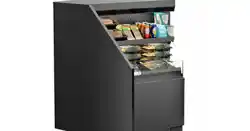
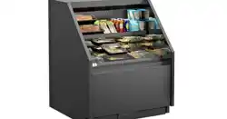
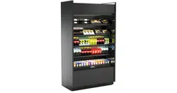
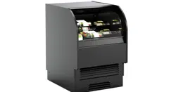
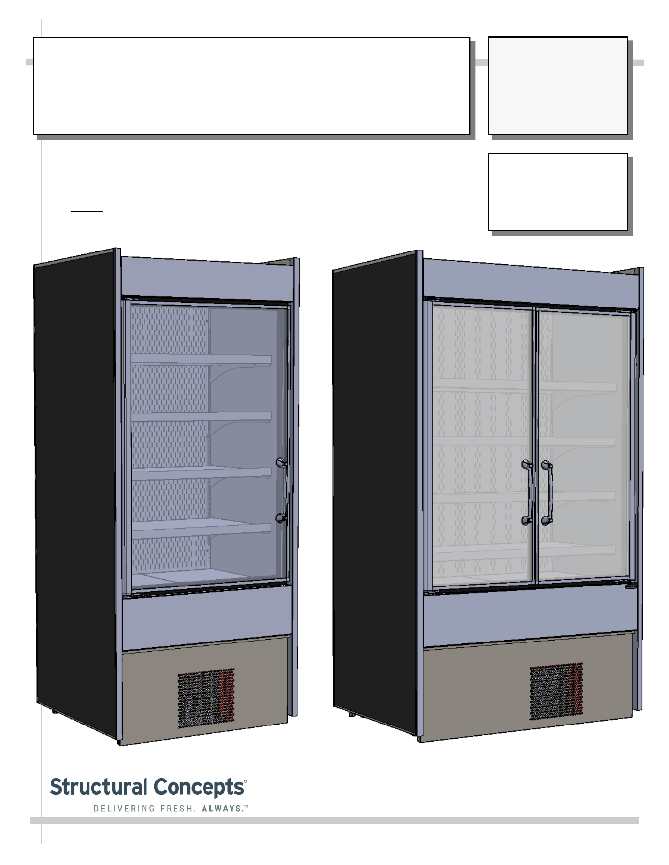
OASIS® REFRIGERATED MODEL BD3632 AND BD4732 BOX DOOR CASE
> SELF-CONTAINED REFRIGERATION SYSTEM
> FRONT DOOR NON-LOCKING (STANDARD)
> CASE ADJOINMENT POSSIBLE
> NOTE: THIS UNIT IS NOT INTENDED FOR USE IN LOBBIES OR
LOCATIONS OF EGRESS, SUCH AS HALLWAYS OR PUBLIC CORRIDORS.
Important!
This User Manual Must
Maintain Parity With Its
French Counterpart:
SCC P/N 21-30645.
Oasis
READ AND SAVE THESE INSTRUCTIONS
®
USER
MANUAL
--- Model BD4732 (Shown Above) With Two Doors ---
--- Model BD3632 (Shown Above) With One Door ---
Structural Concepts Corp. ∙ 888 E. Porter Rd ∙ Muskegon, MI 49441 Phone: 231.798.8888 Fax: 231.798.4960 ∙ www.structuralconcepts.com
SCC P/N
21-29855
2
TABLE OF CONTENTS
OVERVIEW: REF. TEMPS, NSF/ANSI TYPE, COMPLIANCE, REF. DISCL. STATEMENT ..………...
OVERVIEW, CONT’D: DANGER (RISK OF FIRE OR EXPLOSION), CAUTION (AREA, CASE
PLACEMENT GUIDELINES, CHILD-PROOFING CASE, REFRIGERANT RECOVERY, ETC.)..
OVERVIEW, CONT’D: CAUTION (SHELF LOADS LIMITS, LAMPS, GFCI, ETC.) ……………………….
OVERVIEW, CONT’D: ENGLISH TO FRENCH LANGUAGE TRANSLATION …………….……………...
INSTALLATION: CASE REMOVAL FROM SKID / POSITIONING / LEVELER ADJUSTMENT ...…...
GENERAL MERCHANDISER ILLUSTRATION - MODEL BD3632 …...……………………………….
FRONT/REAR PANEL REMOVAL / CONNECTIONS CHECK / TURNING ON POWER TO CASE …..
LED LIGHT FIXTURES .…………………………………………………………………………………..…....
LOAD LEVEL GUIDE / TEMPERATURE GUIDE (MODEL BD3632 SHOWN/APPLICABLE TO
BD4732) ………………………………………………………………………………………………….
CLEANING SCHEDULE (TO BE PERFORMED BY STORE PERSONNEL) …..……………...…….….
PREVENTIVE MAINTENANCE - TO BE PERFORMED BY TRAINED SERVICE PROVIDERS ....…..
TROUBLESHOOTING (TO BE PERFORMED BY TRAINED SERVICE PROVIDER ONLY) …………
TROUBLESHOOTING - R-290 CONDENSING SYSTEM (BY TRAINED SERVICE PROVIDERS) .....
TROUBLESHOOTING - R-290 EVAPORATOR SYSTEM (BY TRAINED SERVICE PROVIDERS) ....
SERIAL LABEL LOCATION & INFORMATION LISTED / TECH INFO & SERVICE ……….…….……
PROGRAMMABLE CONTROLLER INFORMATION………………………………………..………….…..
TECHNICAL SERVICE CONTACT INFORMATION / WARRANTY INFORMATION …...……………..
3
4
5
6
7
8-11
12
13
14
15
16-18
19-21
22
23
24
25
26
3
OVERVIEW
• These cases are designed to merchandise packaged
products at 41 °F (5 °C) or less product temperatures.
• Product must be pre-chilled to 41 °F (5 °C) or less
product temperatures prior to placing in merchandiser.
• Cases should be installed and operated according to
this operating manual’s instructions to ensure proper
performance. Improper use will void warranty.
NSF/ANSI TYPE II ENVIRONMENTAL CONDITIONS
• This unit is designed for the display of products in
ambient indoor store conditions where temperature and
humidity are maintained within a specific range.
• This NSF/ANSI Type II display refrigerator is intended to
be used where environmental conditions are controlled
and maintained so that ambient temperature does not
exceed 80 °F (27 °C) and 55% relative humidity.
• Due to atmospheric pressure considerations, it is not
recommended that these box door cases operate
beyond 6,562 FASL (feet above sea level) / 2,000 MASL
(meters above sea level). If your facility exceeds this
thresholds, please contact Structural Concepts Corp.
COMPLIANCE
• Performance issues when in violation of applicable NEC,
federal, state and local electrical and plumbing codes
are not covered by warranty. See below.
REFRIGERANT DISCLOSURE STATEMENT
• This equipment is prohibited from use in California with
any refrigerants on the “List of Prohibited Substances”
for that specific end-use, in accordance with California
Code of Regulations, title 17, section 95374.
• This disclosure statement has been reviewed and
approved by Structural Concepts and Structural
Concepts attests, under penalty of perjury, that these
statements are true and accurate.
>> See next page for continuation.
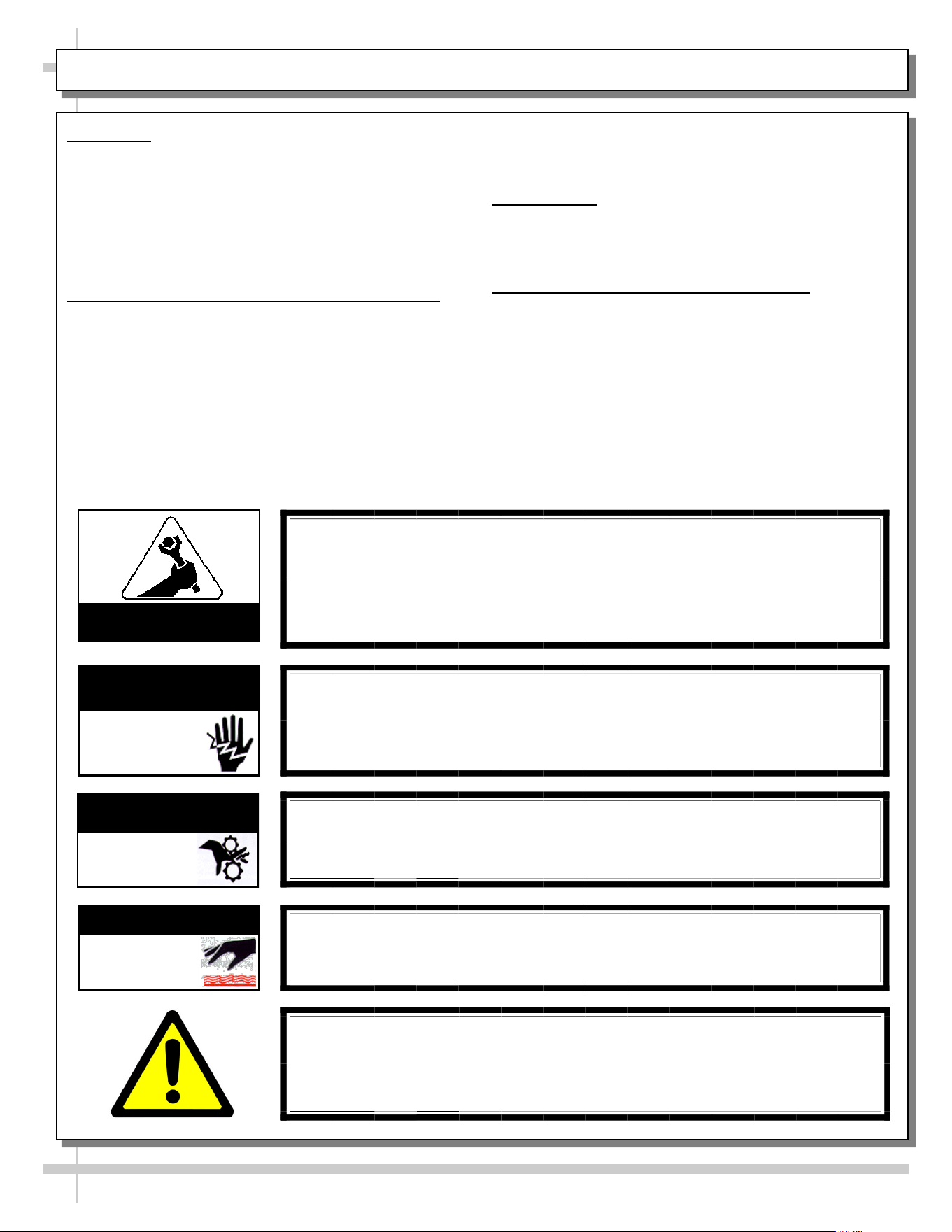
WARNING
Hazardous moving parts. Do not operate unit with covers removed.
Fan blades may be exposed when deck panel is removed.
Disconnect power before removing deck panel.
WARNING
Risk of electric shock. Disconnect power before servicing unit.
CAUTION! More than one source of electrical supply is
employed with units that have separate circuits.
Disconnect ALL ELECTRICAL SOURCES before servicing.
WARNING
Condensate Pan is Hot!
Disconnect and allow to cool before cleaning or removing from case.
WARNING
ELECTRICAL
HAZARD
WARNING
HOT
SURFACE
COMPLIANCE
• These cases MUST be installed in compliance with all applicable NEC,
federal, state and local electrical and plumbing codes.
• These cases must ALSO be installed in accordance with the Safety
Standard for Refrigeration Systems, ANSI/ASHRAE 15.
• ONLY factory authorized service personnel are to service these box cases.
OVERVIEW: REF. TEMPS, NSF/ANSI TYPE, COMPLIANCE, REF. DISCL. STATEMENT - PAGE 1 of 4
ATTENTION
CONTRACTORS
WARNING
This product can expose you to chemicals, including
Urethane (Ethyl Carbamate), which are known to the state of
California to cause cancer and birth defects or other reproductive harm.
For more information go to P65Warnings.ca.gov.
WARNING
KEEP HANDS
CLEAR
4
OVERVIEW, CONT’D
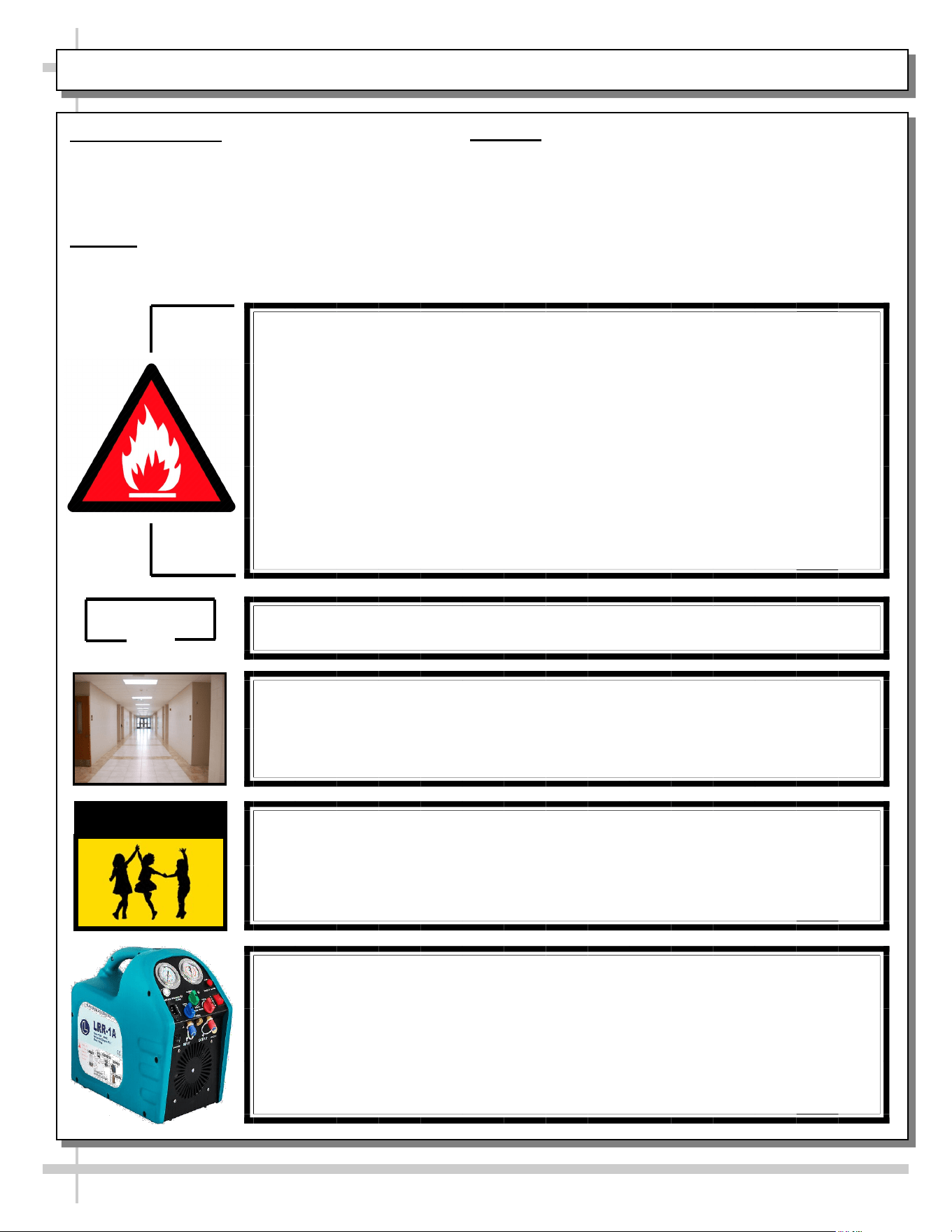
• This sheet details dangers due to flammable
refrigerant. It addresses operational area required,
case placement guidelines, child-proofing the unit
and refrigerant recycling and/or disposal, etc..
DANGER
• Please read section shown below for specifics on
risk of fire explosion, service guidelines, LFL, etc.
CAUTION
• This sheet also details the area required for operation,
areas to avoid placing case, guidelines for children (and
others with limited capabilities) while near box door cases.
• This sheet also provides information on refrigeration
recovery, recycling and disposal.
>> See next page for continuation.
OVERVIEW, CONT’D: DANGER (RISK OF FIRE OR EXPLOSION) / CAUTION (AREA, ETC.) - PAGE 2 of 4
CAUTION
This appliance is not intended for use by persons (including children) with
reduced physical, sensory or mental capabilities, or lack of experience and
knowledge, unless they have been given supervision or instruction concerning use
of the appliance by a person responsible for their safety.
Children should be supervised to ensure that they do not play with the appliance.
DANGER
• Refrigeration unit contains gas under high pressure. Do not tamper with or
puncture the system. Contact qualified service personnel before disposal.
• Risk of fire or explosion. Flammable refrigerant is used in this case.
• Consult repair manual/owner’s guide before servicing this product.
• Do not store explosive substances (such as aerosol cans with a flammable
propellant) in this appliance.
• Do not use an electrical appliance INSIDE the food storage compartments
unless its type is recommended by manufacturer.
• To minimize risk of ignition due to incorrect parts or improper service, this case
is ONLY to be serviced by factory authorized service personnel.
• Flammable refrigerant type specified on case nameplate is on serial label.
• Models BD3632 and BD4732 contain a charge of 150g of R290 refrigerant with a
lower flammability limit (LFL) of .038kg/m³.
CAUTION
≥7.1m²
CAUTION
Minimum room floor area required for operation of these box door cases is ≥7.1m².
CAUTION: REFRIGERANT RECOVERY/RECYCLING/DISPOSAL
• When recycling or discarding case, refrigerants MUST BE handled according to
local, state and federal codes, requirements and regulations.
• If disposing of a refrigerated case that uses ozone depleting chemicals in its
refrigeration system, make sure the refrigerant is removed by a qualified
service technician and properly disposed of.
• If you intentionally release refrigerant into the atmosphere, you may be subject
to fines or other penalties (under regulations mandated by environmental
regulators and/or legislative edict).
CAUTION
• These box door cases are NOT to be installed in lobbies or locations of egress,
such as hallways, public corridors.
• If case is placed in an enclosure or surrounding structure, keep all of the case’s
ventilation openings clear of obstructions.
5
OVERVIEW, CONT’D
CAUTION
• This sheet contains cautionary notes and information
on shelving load limits, lamp replacement, GFCI
(Ground Fault Circuit Interrupters) breaker use,
CAUTION! GFCI BREAKER USE REQUIREMENT
If N.E.C. (National Electric Code) or local code requires GFCI (Ground Fault
Circuit Interrupter), use a GFCI breaker in lieu of a GFCI receptacle.
CAUTION! LAMP REPLACEMENT GUIDELINES
LED lamps reflect specific size, shape and design.
Any replacements must meet factory specifications, resist breakage
and reflect similar appearance as lamps from factory.
CAUTION! POWER CORD AND PLUG MAINTENANCE
Risk of electric shock. If cord(s) and/or plug(s) becomes damaged,
replace only with cord(s) and/or plug(s) of same type.
CAUTION! CHECK CONDENSATE PAN, POSITION & CONNECTIONS!
Water on flooring can cause extensive damage!
• Before powering up case, check that condensate pan is positioned directly
under case’s condensate drain.
• Also, check that there are NO LOOSE CONNECTIONS, including overflow
condensate pan and its power cord plug (if part of the condensate package).
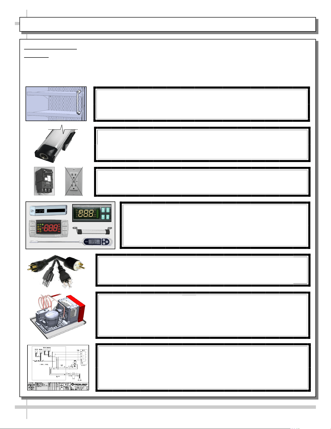
CAUTION! DO NOT RELY ON THERMOMETERS OR
THERMOSTATS FOR PRODUCT (FOOD) TEMPERATURES
• Thermometers & thermostats reflect air temperatures ONLY.
• For ACTUAL product (food) temperatures, use a calibrated food
probe thermometers ONLY.
• For accurate readings, DO NOT use infrared food thermometers.
WIRING DIAGRAM FORMAT & LOCATION
• Each case has its own wiring diagram folded and in its own packet.
• Wiring diagram placement may vary; it may be placed near ballast box, field
wiring box, raceway cover, or other related location.
• Adjoined cases MUST BE connected to each other so that vending controls
system can communicate with adjoined case.
CAUTION! SHELVING LOAD LIMITS / PRODUCT PLACEMENT / TEMP. GUIDE
25 kg per meter² maximum weight allowed per shelf.
See LOAD LEVEL GUIDE section in this User Manual for
product placement guidelines and expected temperature variations.
OVERVIEW, CONT’D: CAUTION (SHELF LOADS LIMITS, LAMPS, GFCI, CORDS, ETC.) - PAGE 3 OF 4
thermometers, thermostats, power cord/plug
maintenance, checking condensate pan, and wiring
diagram format & location.
• Wiring diagram format & location information is also
provided below.
• Please read carefully!
6
OVERVIEW, CONT’D
ENGLISH TO FRENCH LANGUAGE TRANSLATION
Structural Concepts markets its products in countries with both English and French as their official languages.
As with any translation, their can be issues to contend with. Here are a few:
• There can be abbreviations. When translating abbreviated words to a different language, readers of translated text
can be confused as to what meaning the abbreviated words were to convey. Abbreviations have been removed from
the English text so that the translation into French is more understandable.
• There can be language structure differences (which can vary widely between languages). For example, in the
English language, the adjective is placed before the noun; but in French, the adjective comes after the noun.
• There can be missing terms (which can be difficult to translate if there is no equivalent term in the target language).
• There can be compound words (usually a combination of two or three nouns and adjectives) that can be difficult to
maintain accuracy.
• There can be verbs made up of two words (usually a combination of a verb and a proposition). Examples are break
down, fill up, etc.). These can sometimes be translated inaccurately.
• There can word with several meanings (depending on how it is used in a sentence).
• There can be specialized knowledge which may be required to translate technical texts.
Structural Concepts utilizes the latest language translation software available on the market today to translate its
English written documents into French. It employs a well-maintained revision system to constantly update its
documentation (whether in English or French) whenever warranted.
If there be a sentence, phrase or term that can be more accurately translated, please contact Structural Concepts at the
following email address: TechService@StructuralConcepts.com.
OVERVIEW, CONT’D: ENGLISH TO FRENCH LANGUAGE TRANSLATION - PAGE 4 OF 4
7
Support case
while rolling
down ramp.
--- Rotated View of Model BD3632 ---
INSTALLATION: CASE REMOVAL FROM SKID / POSITIONING / LEVELER ADJUSTMENT
Shipping
Bracket
Front
Panel
Leveler
(Typical)
Adjustable
Wrench
Indexing Flat
Pry Bar
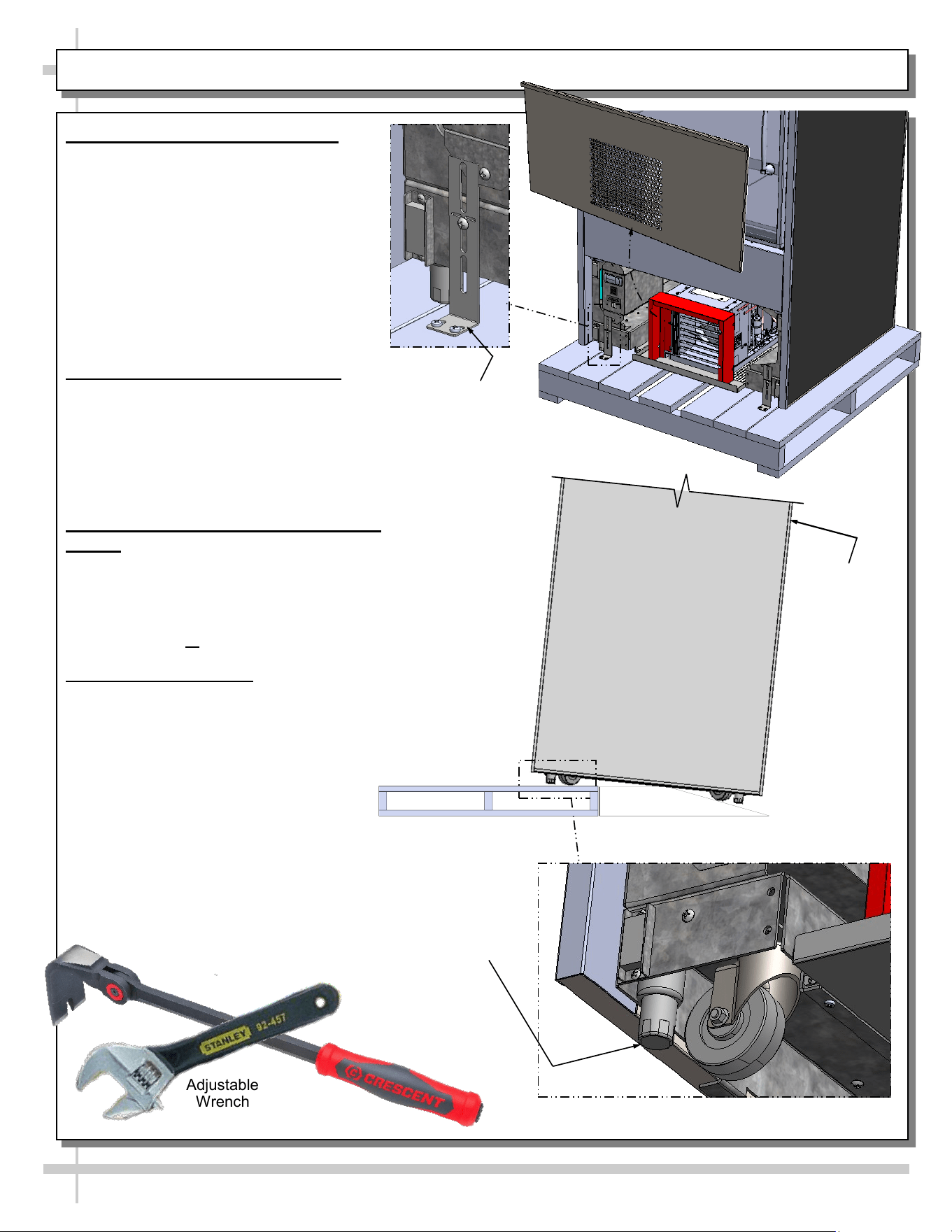
1. Disconnect Case From Skid
• Remove front and rear panels.
• Also, remove shipping brackets that
secure casters to skid
• Important! Case is shipped with levelers
in the DOWN position (for stability). To
prevent damage to the case, all levelers
must be raised ALL THE WAY UP before
moving unit off skid and into position.
• After levelers are raised, place ramp up
against skid (to allow case to smoothly
roll off from skid).
2. Roll Case Off Skid via Ramp
• Maintain support of case at all times or
center of gravity may cause case to fall.
• Roll unit to rear of skid.
• Check that ramp is secure and possibly even
attached to skid with screws.
• Carefully roll down ramp and off skid.
3. Position & Align Alongside Other
Cases
• Before adjusting levelers, make certain that the
case is in proper position and, if required,
aligned with adjoining case(s).
• This may require repositioning of the case you
are installing or the already positioned cases.
4. Adjusting Levelers
• Important! After case is in proper position,
levelers must then be LOWERED to floor.
• Adjust levelers so the case is level and plumb.
Depending upon case weight it may be
necessary to use an indexing flat pry
bar (or similar pry bar) to do so.
• Use adjustable wrench to adjust leveler.
• Do not use indexing flat pry bar on
end panel as it may chip.
• Use indexing flat pry bar ONLY on base frame to
avoid damaging case.
• See illustrations at right.
• After case if level and plumb, you may replace
front and rear panels.
Model BD3632 Is Shown. It May
Not Reflect Every Feature or
Option of Your Particular Case.
8
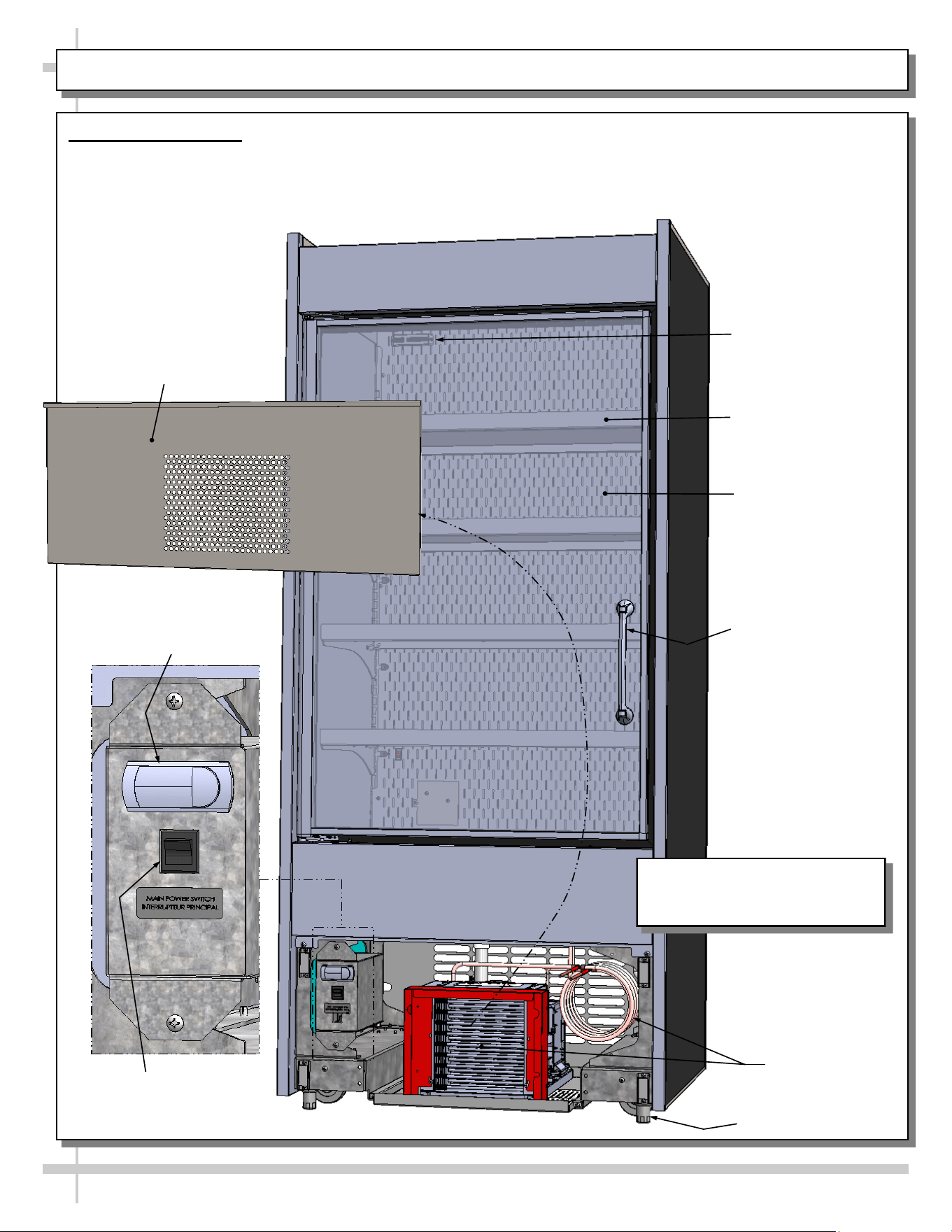
GENERAL MERCHANDISER ILLUSTRATION - MODEL BD3632 - PAGE 1 of 4
1. Front View of Case
• View is shown with front panel removed (for
electrical box & condenser package viewing).
• Vending controls system (monitor, payment
processor, locks, etc.) is at right side of case.
• Shelves/dividers have weight sensors for product
weighing and pricing.
Condenser
Package
Programmable
Controller
Main Power
Switch
Door Handle
Front Panel
Shown Removed
Shelf (Typ.)
Rear Plenum
Leveler (Typ.)
Thermometer
9
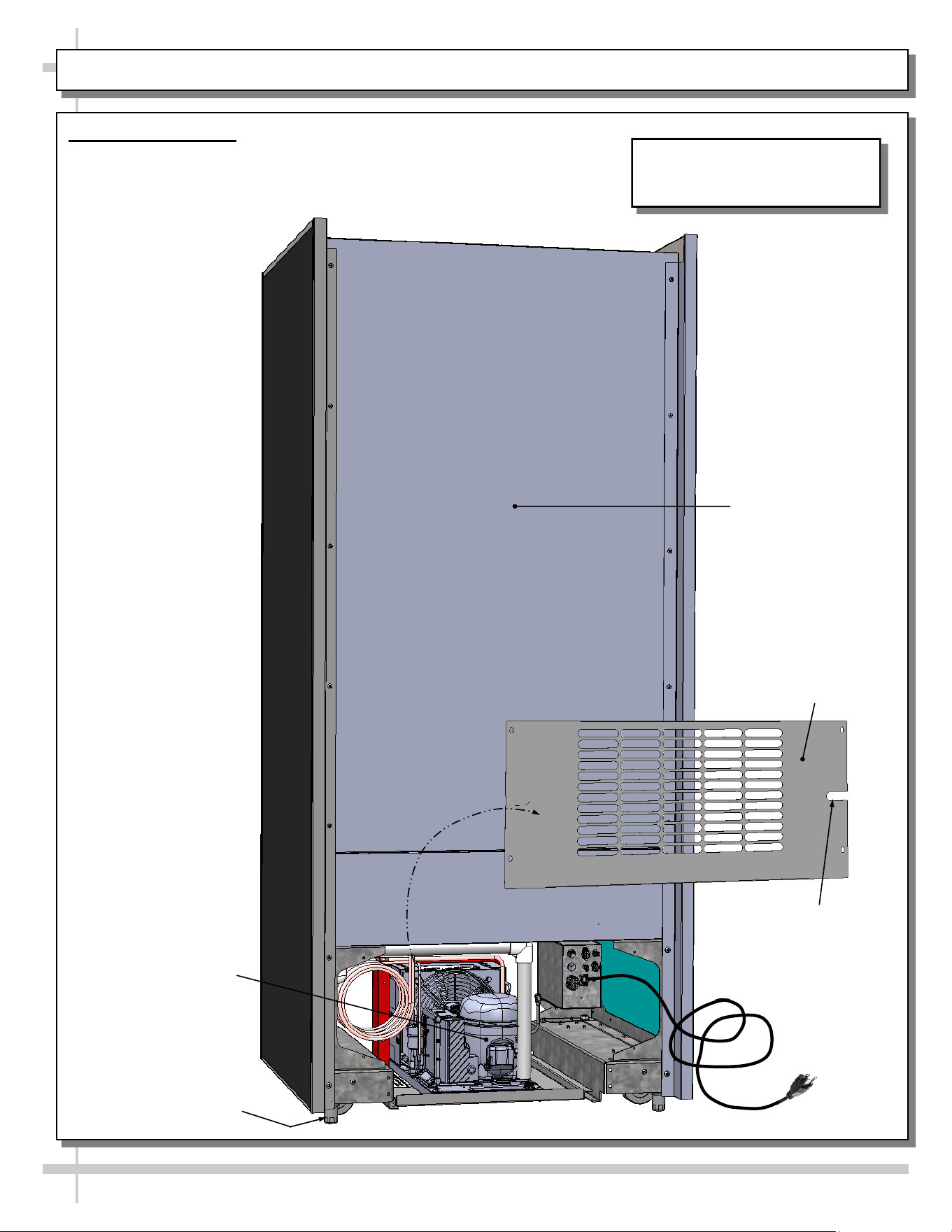
GENERAL MERCHANDISER ILLUSTRATION - MODEL BD3632 - PAGE 2 of 4
2. Rear View of Case
• Rear panel is shown removed to show access to condenser
package and electrical box.
• Vending Control System is at rear-left of case.
Power Cord
Rear Panel
Shown Removed
Power Cord Slot
Rear Panel
Condenser
Package
Leveler (Typ.)
Model BD3632 Is Shown. It May
Not Reflect Every Feature or
Option of Your Particular Case.

10
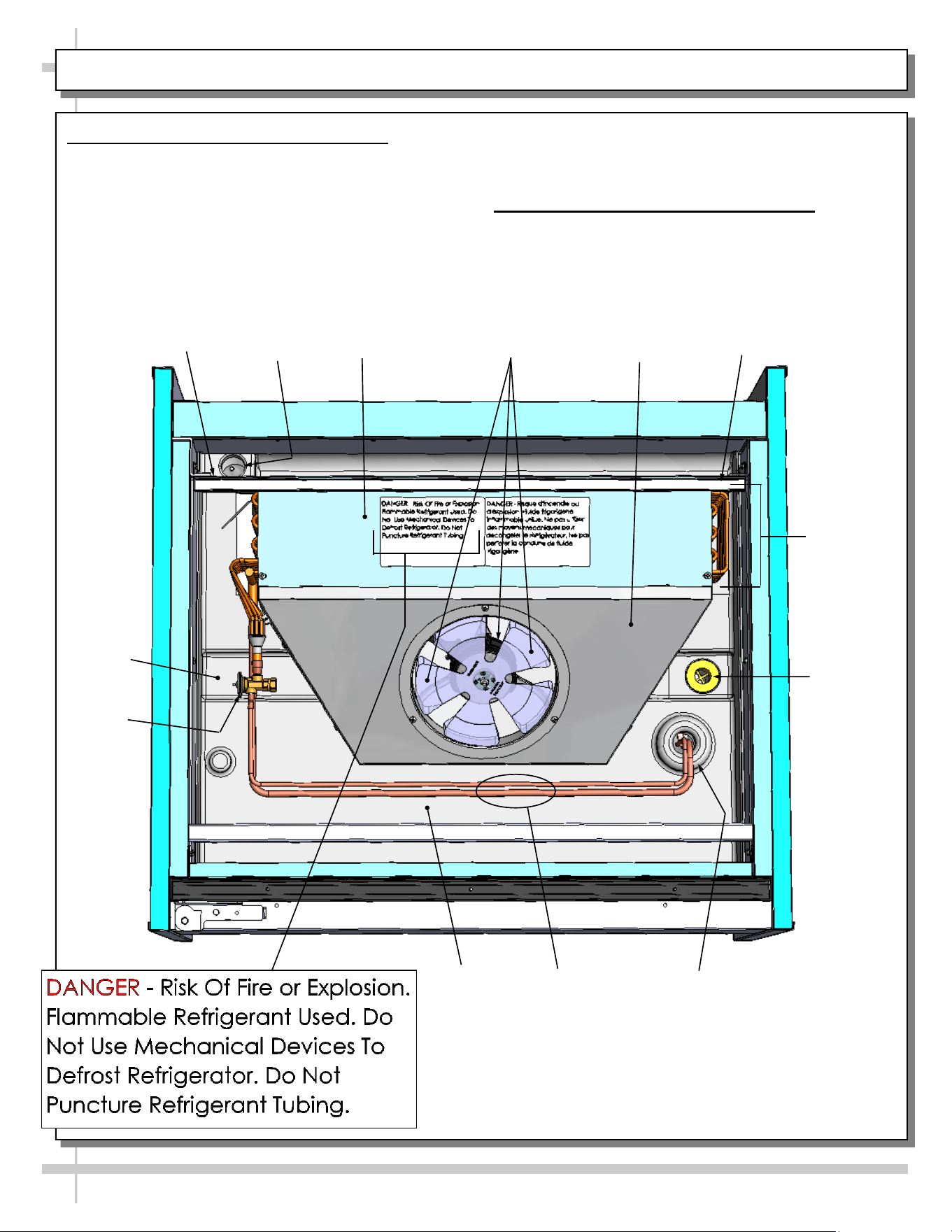
GENERAL MERCHANDISER ILLUSTRATION - MODEL BD3632 - PAGE 3 of 4
3. Self-Contained Hot Gas Loop Condensate Package (Shown Rotated 180°)
• Caution: Only trained service providers are to provide maintenance and service to unit.
• Warning! Disconnect power before providing maintenance and service to unit.
• Important: Carefully read all Warning/Caution/Danger labels on unit!
Compressor
Filter Dryer
Compressor
Inverter
Condenser
Fan & Housing
Courtesy Loop
Condenser Coil
Housing
Hot Gas Loop
Condensate
Pan
Refrigeration
Lines
Model BD3632 Is Shown. It May
Not Reflect Every Feature or
Option of Your Particular Case.
11
GENERAL MERCHANDISER ILLUSTRATION - MODEL BD3632 - PAGE 4 of 4
5. Evaporator Coil Fans / Air Discharge
When case is energized, refrigeration will be provided.
• Evaporator coil fan should turn on.
• From inside of the case, check for discharge air
from honeycomb discharge duct to confirm that
the fan is functioning properly.
Drain
Wire
Route
Trough
Refrigeration
Line Route
Refrigeration
Lines
TXV
Evaporator
Fan Shroud
• When the case is in a start-up mode or has been
idle for a long period of time, the unit will require
75-minutes of run time to pull-down temperature.
6. TXV (Thermostatic Expansion Valve)
• TXV (at customer front-left side of case).
• Decking must be removed for access.
• See illustration below for TXV location.
Close-Off
Coil
Cover
Tub
Close-Off
Evaporator
Coil
Evaporator Fan
& Blades
12
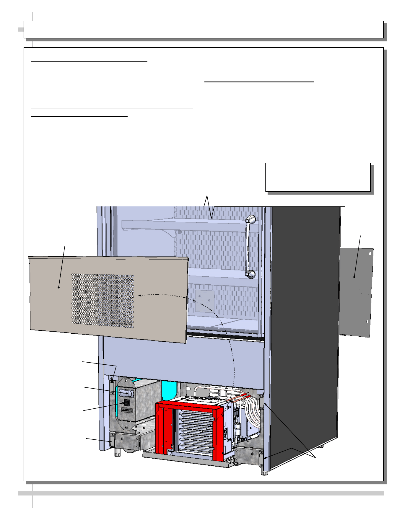
FRONT/REAR PANEL REMOVAL / CONNECTIONS CHECK / TURNING ON POWER TO CASE
1. Removable Front/Rear Panel
• Front and rear panel can be removed/replaced
by simply grasping top ‘lip’ and pulling
outward, freeing it from magnets.
• See illustration below.
2. Check Condenser Package Connections
Before Powering Up Case!
• Caution! Connections can come loose
during shipment; this can allow water to
overflow onto floor, causing damage!
• When case in is proper location, remove front
and rear panels to check for loose
connections, including overflow condensate
pan and its power cord plug (if part of the
condensate package).
• See TROUBLESHOOTING section in operating
manual for various troubleshooting issues.
3. Turning On Power To Case
• Plug in power cord.
• Turn on main power switch (at lower left).
• Return front and rear panels to case.
• Check that programmable controller is energized.
• Open door: check that LED light in upper plenum
is energized and that evaporator fans are rotating.
Magnet
Front Panel
Main Power
Switch
Magnet
Magnets
Programmable
Controller
Rear Panel
Model BD3632 Is Shown. It May
Not Reflect Every Feature or
Option of Your Particular Case.
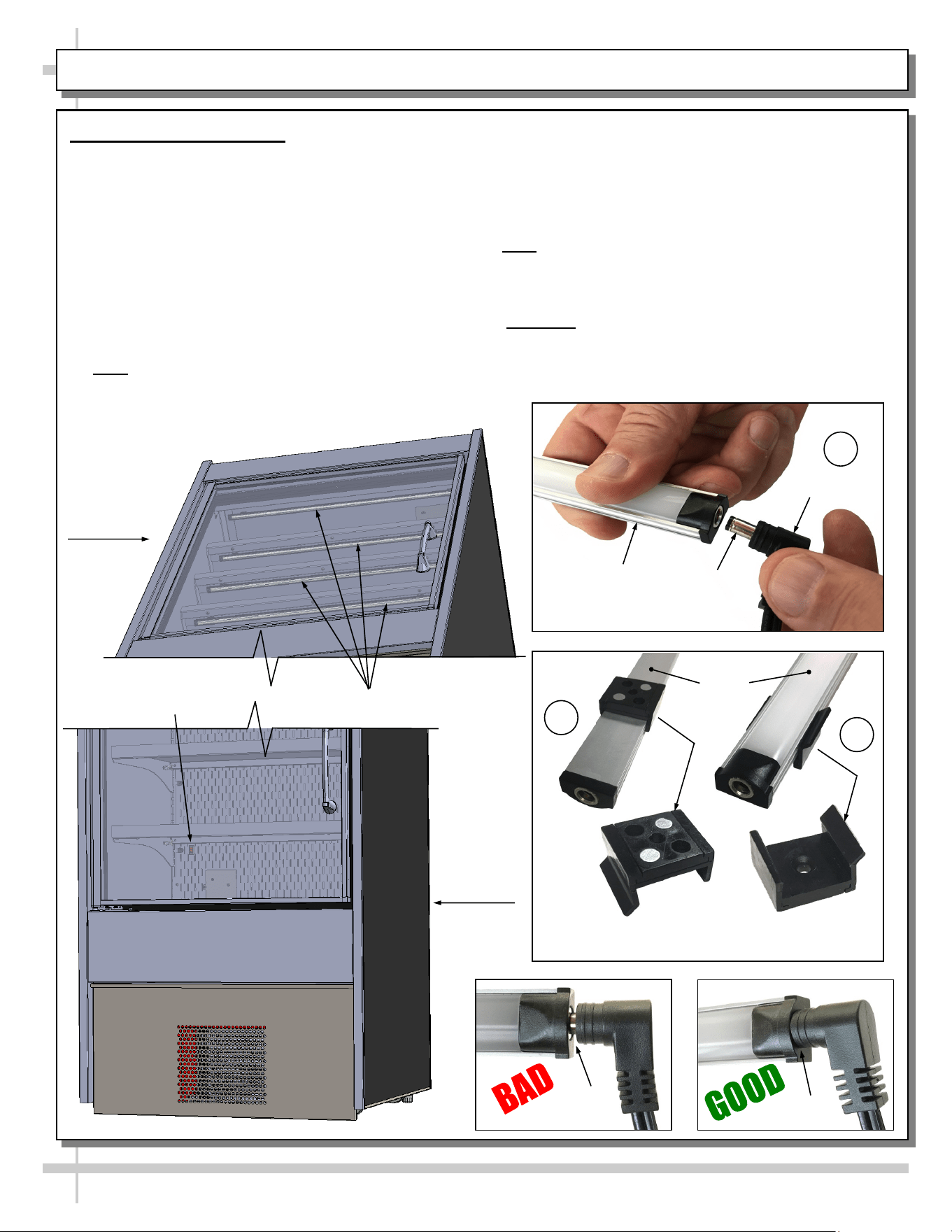
LED Style Light Fixtures
Removal of Faulty LED Lights:
• Contact Structural Concepts’ Technical Service
Department for replacement LED lights.
• Turn off LED light switch.
• To remove faulty LED light, follow these steps:
A. Disconnect plug from LED light.
B. Using both hands, grasp LED light assembly
(with its magnetic mounting clips). Pull
downward and off its shelf (or header).
C. Remove magnetic mounting clips from LED
light by pressing against flange part of clip with
thumb.
>> Note: Mounting clips MAY be riveted to header.
Simply remove LED light from mounting clips by
pressing against flange part of clips with thumb.
13
LED LIGHT FIXTURES
Replacement of LED lights:
• Attach magnetic mounting clips onto LED light.
• Adjust magnetic mounting clips so they are equally
spaced on LED light.
• Reattach LED light assembly to its shelf/header.
• Position properly in shelf/header.
>> Note: If mounting clips are riveted to shelf (or header),
attach by placing LED in base of clip and then snapping
into clip at FLANGE SIDE.
• Press plug’s barrel-shaped insert deep into LED light.
• Important: If plug is not inserted ALL THE WAY IN the
LED light’s orifice, the light may not energize. See
“BAD” vs. “GOOD” insertion illustrations below.
• Turn LED light switch back on.
Lower
Case Area
Magnetic Mounting
Clip View #2
LED
Lights
B
A
Plug
Barrel
Shaped
Insert
LED
Light
C
Magnetic Mounting
Clip View #1
No Gap
Gap
LED Light Switch
LED Lights (Typ.)
Upper
Case Area
14
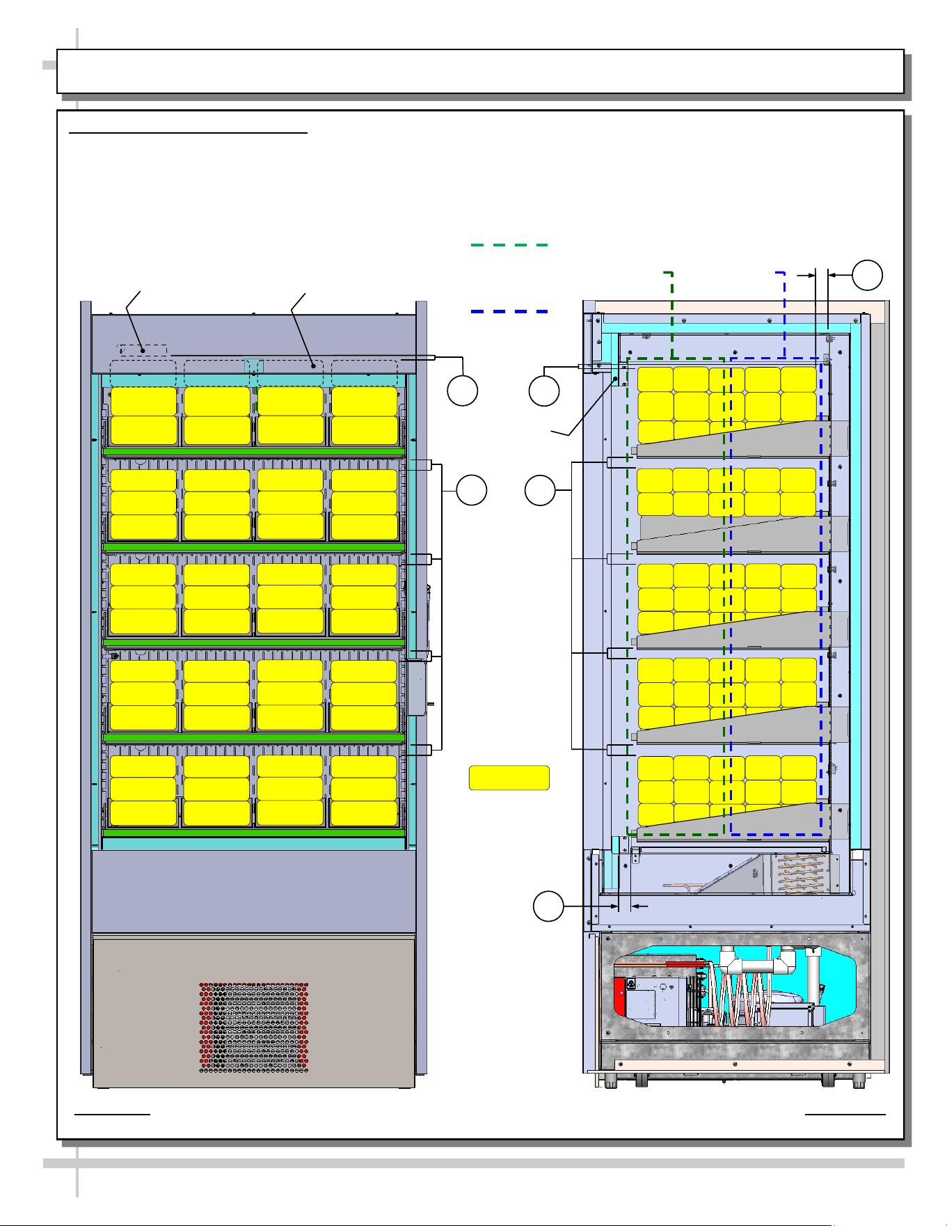
LOAD LEVEL GUIDE / TEMPERATURE GUIDE (MODEL BD3632 SHOWN/APPLICABLE TO BD4732)
LOAD LEVEL & TEMPERATURE GUIDE
>> FOLLOW THESE PRODUCT PLACEMENT GUIDELINES TO
MAINTAIN DESIRED PRODUCT TEMPERATURES.
>> NOTES CORRESPOND WITH ILLUSTRATIONS SHOWN.
>> CAUTION! DO SUBJECT SHELVES TO EXCESSIVE LOADS.
1. AT TOP SHELF, KEEP PRODUCT BELOW THERMOMETER
(THAT IS ATTACHED TO REAR PERFORATED PLENUM).
2. ALLOW AT LEAST 1” SPACE BETWEEN PRODUCT AND ITS
SHELF ABOVE.
3. AT CASE REAR, ALLOW AT LEAST 1” SPACE BETWEEN
PRODUCT AND REAR PERFORATED PLENUM.
4. DO NOT BLOCK 1 1/4” AIR RETURN OPENING WITH PRODUCT.
>> IF YOU ARE UNABLE TO MAINTAIN DESIRED PRODUCT
TEMPERATURES, SEE TROUBLESHOOTING SECTION IN MANUAL.
38 °F TO 41 °F
PRODUCT AT
CASE FRONT
28 °F To 35 °F
PRODUCT AT
CASE REAR
THERMOMETER
MODEL BD3632 SHOWN ABOVE (APPLIES TO BD4732). CASE IS PARTIALLY DISASSEMBLED,
CROSS-SECTIONED AND PACKAGED PRODUCT LADEN FOR ILLUSTRATIVE PURPOSES ONLY.
PRODUCT BEHIND HEADER
SHOWN WITH HIDDEN LINES (TYP.)
HEADER
PACKAGED
PRODUCT
ILLUSTRATION
PRODUCT
TEMPERATURE
RANGE SHOWN
AT RIGHT.
2
1
2
1
3
4
IMPORTANT!
25 kg per
meter²
maximum
weight
allowed per
shelf!
15
CLEANING SCHEDULE - PERFORMED BY STORE PERSONNEL
FREQ. INSTRUCTIONS
Daily Inner Metal Components (Shelves, Decks, Rear Perforated Plenum, Inner End Panels, Etc.):
• Wipe with cloth dipped in mild-soapy water. Dry with soft cloth.
Outer Metal Components (Door Frame, Door Handles, Lower Panels, End Panels, Etc.):
• Wipe with cloth dipped in mild-soapy water. Dry with soft cloth.
Daily Glass Surface (Door):
• Clean inside and out with household or commercial glass cleaner. Dry with soft cloth or paper towel.
16
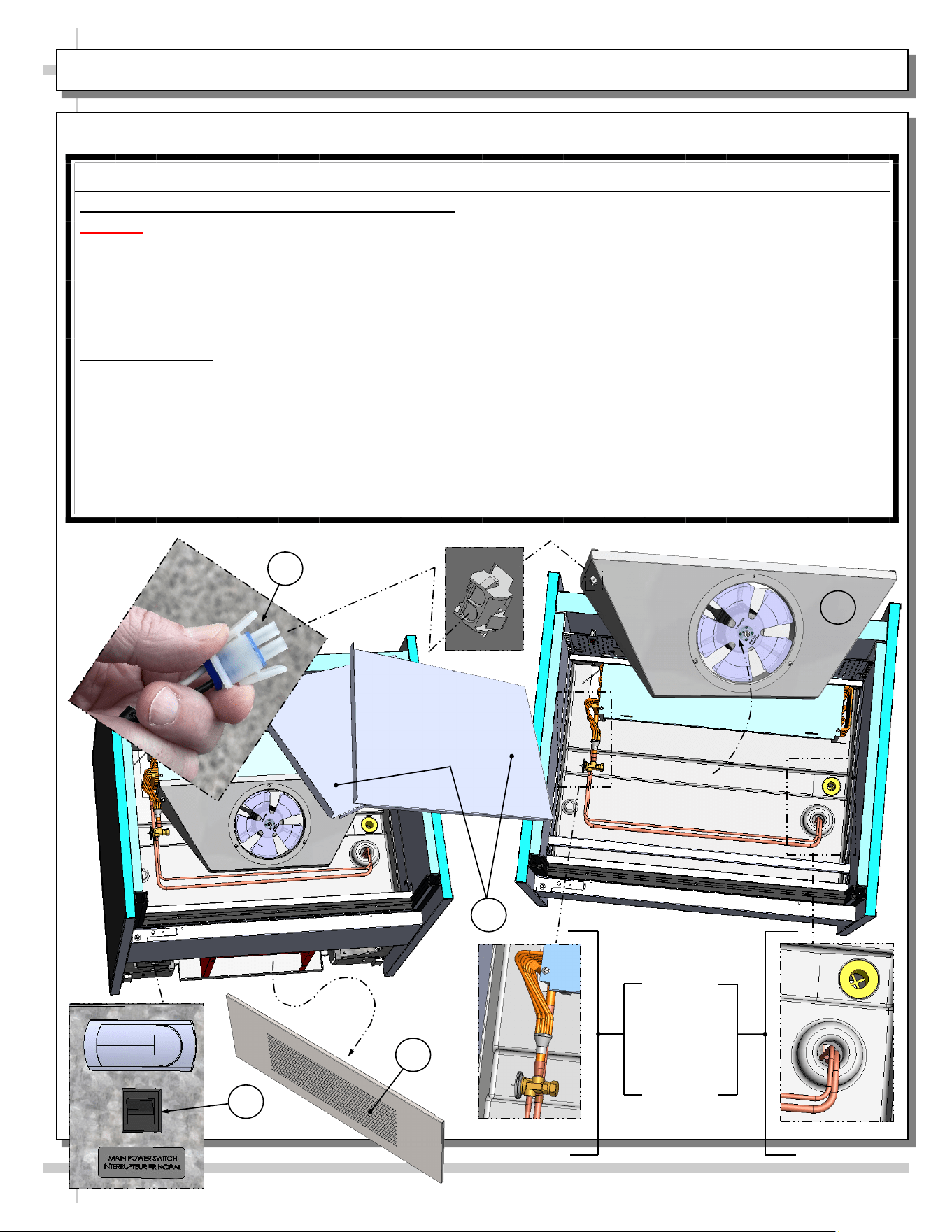
WARNING! TURN OFF CASE BEFORE PERFORMING PREVENTIVE MAINTENANCE!
QUARTERLY PREVENTIVE MAINTENANCE INSTRUCTIONS
Tub, Coil, Drain, Fan Blades, Motors, Brackets:
Caution! Do Not Clean or Perform Service On Unit While It Is Energized!
1. Remove front panel (to access controls). No screw removal is required. Place in safe place away from
foot traffic.
2. Turn off main power switch (located near programmable controller).
3. Remove deck pans. Place in safe place away from foot traffic.
4. Disconnect power cord that energized fan panel.
5. Grasp fan shroud assembly. Lift up and away from case. Place in safe place away from foot traffic.
Cleaning Process:
• Use vacuum to remove excessive residue AND to remove dust in coil.
• Use clean cloth and/or nylon brush with warm water and mild soap solution to clean tub, drain, trough,
TXV, lines, solenoid, coil & coil tubes. See enlarged view of components to be cleaned (lower-right).
• Remove debris that may clog drain.
• Wipe down fan blades, motors and brackets with moist cloth. Dry components with paper towel.
Returning Components / Restoring Power To Case:
• Replace/reconnect components in reverse order they were removed or disconnected.
• Turn main power switch back on. Check that fans are operational.
PREVENTIVE MAINTENANCE - TO BE PERFORMED BY TRAINED SERVICE PROVIDERS ONLY - 1 of 2
3
2
1
Enlarged
View Of
Components
To Be
Cleaned
4
5
17
WARNING! TURN OFF CASE BEFORE PERFORMING PREVENTIVE MAINTENANCE!
QUARTERLY PREVENTIVE MAINTENANCE INSTRUCTIONS, CONT’D
Under Case Cleaning:
Caution! You must turn main power switch off before cleaning!
• Remove front and rear panel (no screw removal required).
• Remove shipment screws from condenser package (if still intact).
• Carefully slide condenser package out from under case. Caution! Be careful not to kink or damage
courtesy loop!
• At case rear, vacuum (or broom) under case to remove all dust, debris and dirt that may collect.
Condensate Package:
Caution! You must turn main power switch off before cleaning!
• Remove front panel. Turn main power switch off and allow components to cool.
• Carefully and slowly slide condensate package out from under case.
• Use a soft-bristled scrub-brush and non-corrosive de-scaling solution (to remove calcium, lime and
rust) from condensate pan. Wipe down courtesy loop. Follow de-scaling solution’s instructions as to
proper dilution and safety precautions.
• After thoroughly cleaning pan with brush and solution, rinse thoroughly with clean water
(in spray bottle) and wipe dry with sponge or paper towel.
• Use moist cloth to wipe off dust & debris that collects on various parts (hot gas loop condensate pan,
compressor fan, blades and housing, fans, sight glass (if any), refrigeration lines, courtesy loop,
overflow pan (if any), etc.
• Slide condensate package back under case.
• Return front panel to case.
• See GENERAL MERCHANDISER ILLUSTRATION - MODEL BD3632 - PAGE 3 of 4 in this
operating manual for condensate package illustration.
PREVENTIVE MAINTENANCE - TO BE PERFORMED BY TRAINED SERVICE PROVIDERS ONLY - 2 of 2
18
CONDITION TROUBLESHOOTING
Case Not
Lining Up
See INSTALLATION section in this manual for instructions on properly aligning case
(alongside other cases) and adjusting levelers.
Water Is On
The Floor
Caution! Water on flooring can cause much damage! Until cause is determined (and
repaired), follow these procedures:
• Use wet-dry vacuum (or mop & bucket) to remove standing water.
• Use ‘catch pans’ for water to drain into. Swap out regularly until case has completely
drained.
Check that the drain trap is free from debris.
Check that the drain hose/pipe is correctly positioned over condensate pan (or floor drain,
for remote units).
Check store conditions. To prevent condensation in NSF/ANSIType II environments,
conditions are to be 55% maximum humidity / 80° Fahrenheit (27° Celsius) maximum
temperature.
Check that condensate pan components have no loose connections.
Check that overflow condensate pan (if any) has its power cord plug properly plugged into
electrical box.
Check that overflow condensate pan (if any) is not malfunctioning. Its electric rod heater
should be heating up when case is energized.
Caution! Disruption of power can cause water to overflow pan and seep onto flooring
causing damage! Check that power to case is constant. Until power is restored, follow
these procedures:
• Use wet-dry vacuum (or mop & bucket) to remove standing water.
• Use ‘catch pans’ for water to drainage. Swap out regularly until drainage of case is
complete (or until power is restored).
• When power to case is restored, condensate pan should function properly and water
will no longer overflow onto flooring.
TROUBLESHOOTING (TO BE PERFORMED BY TRAINED SERVICE PROVIDER ONLY) - PAGE 1 of 3
19
CONDITION TROUBLESHOOTING
Fan Emits Excessive
Noise
Check that the case is aligned, level and plumb.
Check evaporator fan for cleanliness.
Unplug/power off fan motor. Check motor shaft for bearing wear.
Check that fan motor is securely mounted in brackets.
Verify that fan blades are securely mounted to fan motor.
Check that nothing is preventing blade rotation.
Check that the fan shroud is properly secured.
Fan Is Not Working Check that the MAIN power switch is on.
Check that fan connector is securely plugged in at fan shroud.
Check that fan connector is securely plugged in near close-off.
Check for foreign material obstructing fan performance.
Check that fan blade freely rotates within fan shrouds
Check that power is going to fans
Check that fan wiring is connected on terminal blocks.
Programmable
Controller Display
Is Blank
Check that the MAIN power switch is on.
Check circuit breaker box for tripped circuits.
Programmable
Controller Display Is
Flashing
See your case’s serial label for your model’s specified settings. See SERIAL
LABEL LOCATION & INFORMATION LISTED / TECH INFO & SERVICE for
label location, etc.
System Not Operating Check that the utility power is on.
Check that the MAIN power switch is on.
Check the circuit breaker box for tripped circuits.
Case Lights Are Not
Working
Check that light switch is in the on position.
Check that ALL of the light cords and plugs are properly connected. See LED
LIGHT FIXTURES section in this manual for specifics.
Service Technicians Only: Check voltage at LED drivers. If voltage is entering
but not exiting, LED driver may be faulty.
TROUBLESHOOTING (TO BE PERFORMED BY TRAINED SERVICE PROVIDER ONLY) - PAGE 2 of 3
20
CONDITION TROUBLESHOOTING
Weight Sensors On
Shelf/Shelves Are
Malfunctioning
Contact Instant Retail Services.
Color-Coded Lights
On Shelf/Shelves
Are Malfunctioning
Contact Instant Retail Services.
Screen/Monitor Is
Malfunctioning
Contact Instant Retail Services.
Payment Processor
Is Malfunctioning
Contact Instant Retail Services.
Case Is Not Holding
Temperature
If a large amount of warm product was added to the case, it will take time for the
temperature to adjust. Please load case with pre-chilled product.
Temperature changes during defrost mode but will return to normal. Fourth LED
will indicate defrost cycle in progress.
Check that case is not directly in the sun.
Check that condenser coil has been cleaned.
Check air return opening for obstructions.
Check sight glass for flashing and/or low charge.
Check set point temperature; it may be adjusted too high.
Condensing Unit Is
Not Operating
Check that the power is turned on.
Check if programmable controller settings are properly set. See your case’s serial
label for your model’s specified settings. See SERIAL LABEL LOCATION &
INFORMATION LISTED / TECH INFO & SERVICE section in manual for label
location, etc.
TROUBLESHOOTING (TO BE PERFORMED BY TRAINED SERVICE PROVIDER ONLY) - PAGE 3 of 3
21
CONDITION TROUBLESHOOTING
Head Pressure Too
High
Check that the condensing coil is not dirty or covered.
Check that condensing fans are working.
Perform sub-cooling check and verify that no contaminates are in system.
Check that liquid line filter dryer is not plugged.
Check that close-offs are intact (around condensing coil) and that air is not recir-
culating.
Check that store ambient temperature isn’t above maximum allowed.
See OVERVIEW / TYPE / COMPLIANCE / WARNINGS / PRECAUTIONS /
WIRING / PLUGS section in this manual.
Head Pressure Too
Low
If sight glass is part of condensing unit, check if it is flashing or showing low charge.
TROUBLESHOOTING - R-290 CONDENSING SYSTEM (BY TRAINED SERVICE PROVIDERS ONLY)
22
CONDITION TROUBLESHOOTING
Low Suction
Pressure
Check if sight glass (if present) is flashing or showing low charge.
Check that expansion valve (TXV) isn’t restricted. Check element charge.
Check that liquid line or filter isn’t restricted. Check that refrigeration line / courtesy
loop is not kinked.
Check that evaporator fan motor is working.
Check that superheat is between 6 °F to 8 °F (-14 °C to -13 °C).
Check that there is no air recirculation around evaporator coil.
Check that evaporator coil is not iced up.
High Suction
Pressure
Check that the “cooling load” isn’t high. Product must be pre-chilled before placing
in refrigerated section of case.
Check that case is at least 15-feet from exterior doors, overhead HVAC vents or
any air curtain disruption.
Check that unit is not exposed to direct sunlight via windows or any other heat
source (ovens, fryers, etc.).
Check that superheat adjustment isn’t low.
Check TXV bulb installation
a. Poor thermal contact.
b. Warm location.
TROUBLESHOOTING - R-290 EVAPORATOR SYSTEM (BY TRAINED SERVICE PROVIDERS ONLY)
23
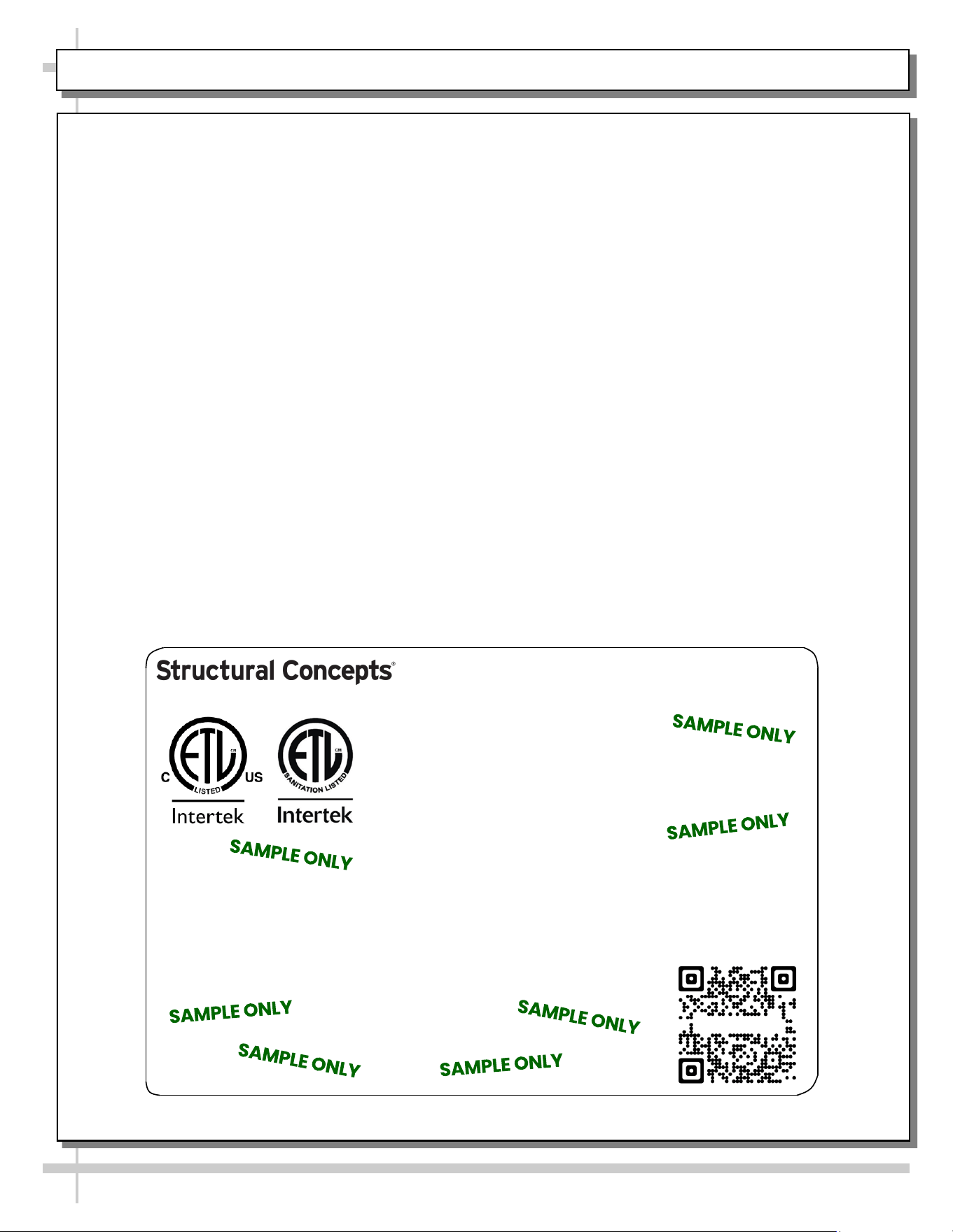
SERIAL LABEL LOCATION & INFO LISTED / TECH INFO & SERVICE / REFRIGERATED CASES ONLY
--- Sample Serial Label For Refrigerated Cases ---
MODEL NRS3648RXV-SAMPLE
SERIAL NO. 12345X30DZ098765
888 E. Porter Rd - Muskegon, MI 49441
3048256
Conforms to UL Std. 471
Conforms to NSF/ANSI Stds. 2 & 7
CERTIFIED TO CAN/CSA
STD C22.2 NO 120
ELECTRICAL RATING
REFRIGERANT
DESIGN PRESSURE
MINIMUM CIRCUIT AMPACITY
MAXIMUM OVERCURRENT
120/1/60 16 A
R513A AMOUNT 50 OZ
HIGH 186 LOW 88
20A
20A
Super Heat Temp 6-8 °F FOR PARTS AND SERVICE
Defrost 6 defrosts per day, 45 °F CALL 1-800-433-9490
Serial Label Location & Information Listed /
Technical Information & Service
• Serial labels are affixed at a wide range of places
(on the header, near thermostat, at case rear,
behind panels/toe-kicks, on electrical boxes, etc.).
• Serial labels contain electrical, temperature and
refrigeration information, as well as regulatory
standards to which the case conforms.
• Sample serial label is shown. A variety of models is
displayed on serial label for illustration purposes only.
Your case’s serial label will reflect only one model.
• For additional technical information and service, see
the TECHNICAL SERVICE page in this manual for
instructions on contacting Structural Concepts’
Technical Service Department.
Reveal
Harmony
Fusion
Impulse
Addenda
Blend
Grocerant
Oasis
Sample QR Code
SCAN FOR PRODUCT LITERATURE
SAMPLE ONLY
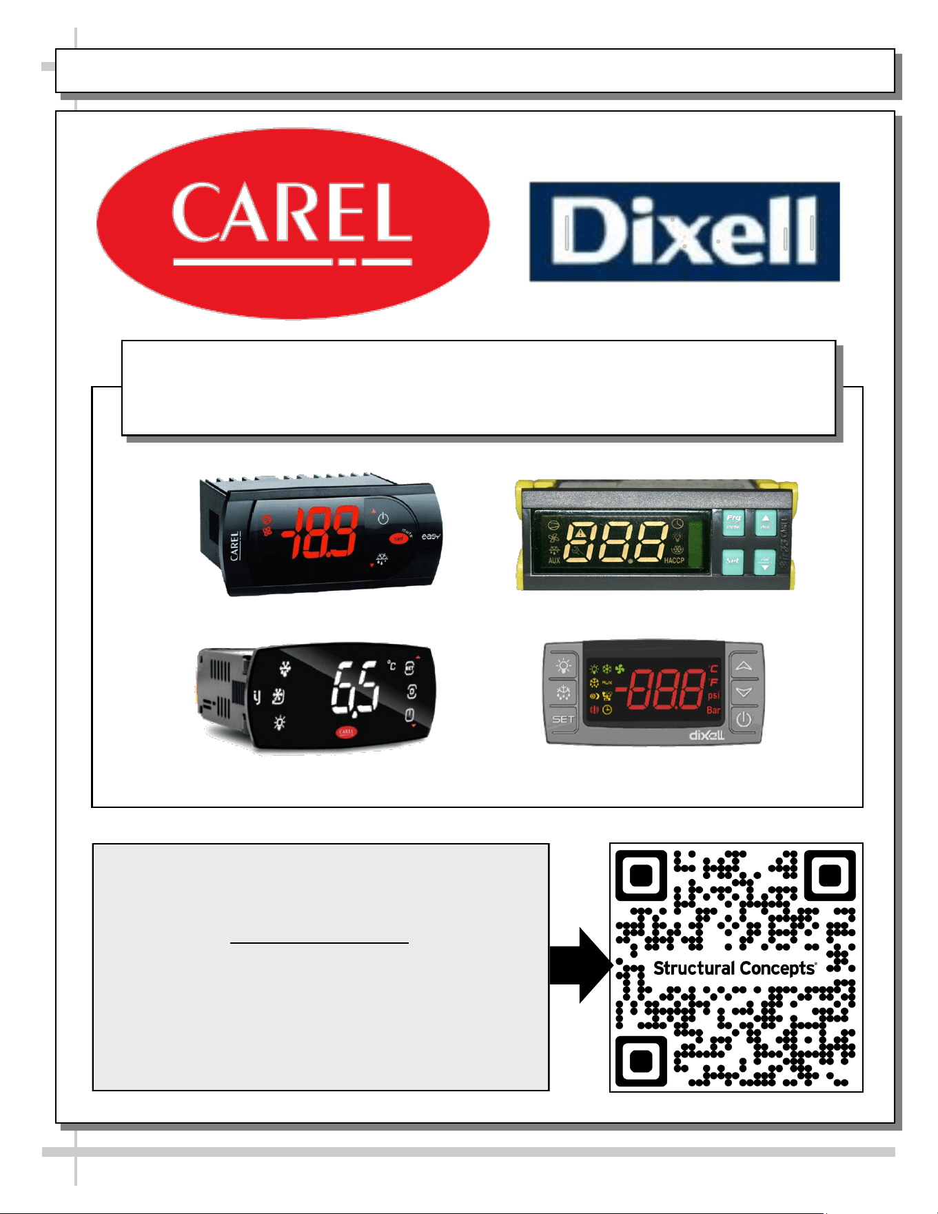
PROGRAMMABLE CONTROLLER (SELECT, CLICK ON OR SCAN QR CODE FOR INFORMATION)
24
Carel® iJF Platform
Carel® PJEZ Platform
Carel® ir33 Platform
Dixell® XM670K-XM679K Platform
To Access Information About The Programmable
Controller That Is Used On Your Case,
Follow These Instructions:
> If Viewing This Document on Smart Phone, Tablet
or Computer, Select/Click On The QR Code at Right.
> If Viewing This Document In Print (Hard Copy),
Scan The QR Code at Right With Your Smart Phone
or Tablet.
Determine Which Programmable Controller Is On Your Case (Controllers
That Are Commonly Used By Structural Concepts Are Shown Below).
Your Particular Programmable Controller May Differ From Units Shown.
STRUCTURAL CONCEPTS TECHNICAL SERVICE CONTACT INFORMATION & LIMITED WARRANTY
25
TECH SERVICE/WARRANTY CONTACT INFO:
1 (800) 433-9490 / EXTENSION 1
DAYS/HOURS AVAILABLE:
MONDAY - FRIDAY (CLOSED HOLIDAYS)
8:00 AM to 8:00 PM EST
YOU MUST HAVE THE FOLLOWING INFO AVAILABLE
BEFORE CONTACTING STRUCTURAL CONCEPTS:
SERIAL NO. / MODEL NO. / STORE NO. / STORE
ADDRESS / DETAILS (PHOTOS, LEAK LOCATIONS,
DAMAGE, STORE’S AMBIENT CONDITIONS, ETC.)
To Access The Limited Warranty To Your
Case, Follow These Instructions:
> If Viewing This Document on Smart Phone,
Tablet or Computer, Select/Click On The QR
Code at Right.
> If Viewing This Document In Print (Hard
Copy), Scan The QR Code at Right With Your
Smart Phone or Tablet.