de
en
User Manual
Bedienungsanleitung
Bridgeable 2-channel amplier with V-AMP Link
Brückbarer 2-Kanal Verstärker mit V-AMP Link
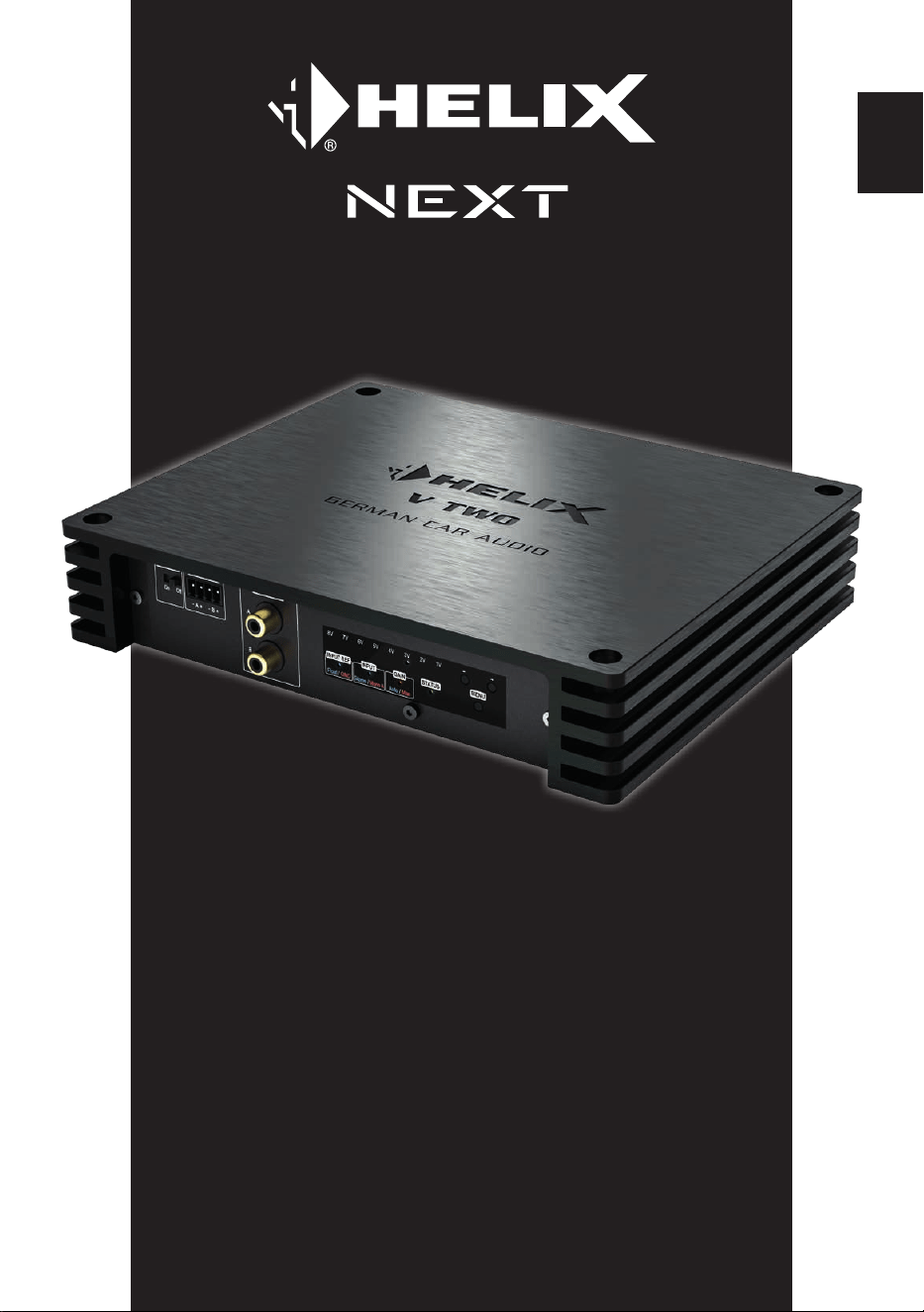
V TWO


3
Sehr geehrter Kunde,
Wir gratulieren Ihnen zum Kauf dieses hochwertigen
HELIX-Digitalverstärkers.
Audiotec Fischer setzt mit der HELIX V TWO neue
Maßstäbe im Bereich der Verstärkertechnik. Dabei
protieren Sie als Kunde direkt von unserer mehr
als 35-jährigen Erfahrung in der Forschung und
Entwicklung von Audiokomponenten.
Dieser Verstärker wurde von uns nach neuesten
technischen Erkenntnissen entwickelt und
zeichnet sich durch hervorragende Verarbeitung
und eine überzeugende Anwendung ausgereifter
Technologien aus.
Viel Freude an diesem Produkt wünscht Ihnen das
Team von
AUDIOTEC FISCHER
Allgemeines zum Einbau von HELIX-Kompo-
nenten
Um alle Möglichkeiten des Produktes optimal aus-
schöpfen zu können, lesen Sie bitte sorgfältig die
nachfolgenden Installationshinweise. Wir garan
-
tieren, dass jedes Gerät vor Versand auf seinen
einwandfreien Zustand überprüft wurde.
Vor Beginn der Installation unterbrechen Sie
den Minusanschluss der Autobatterie.
Wir empfehlen Ihnen, die Installation von einem
Einbauspezialisten vornehmen zu lassen, da der
Nachweis eines fachgerechten Einbaus und An
-
schlusses des Gerätes Voraussetzung für die
Garantieleistungen sind.
Installieren Sie Ihren Verstärker an einer trockenen
Stelle im Auto und vergewissern Sie sich, dass der
Verstärker am Montageort genügend Kühlung er
-
hält. Montieren Sie das Gerät nicht in zu kleine, ab-
geschlossene Gehäuse ohne Luftzirkulation oder
in der Nähe von wärmeabstrahlenden Teilen oder
elektronischen Steuerungen des Fahrzeuges. Im
Sinne der Unfallsicherheit muss der Verstärker
professionell befestigt werden. Dieses geschieht
über Schrauben, die in eine Montageäche ein
-
geschraubt werden, die wiederum genügend Halt
bieten muss.
Bevor Sie die Schrauben im Montagefeld befes
-
tigen, vergewissern Sie sich, dass keine elek-
trischen Kabel und Komponenten, hydraulische
Bremsleitungen, der Benzintank etc. dahinter ver
-
borgen sind. Diese könnten sonst beschädigt wer-
den. Achten Sie bitte darauf, dass sich solche Teile
auch in der doppelten Wandverkleidung verbergen
können.
Allgemeines zum Anschluss des V TWO Ver
-
stärkers
Der Verstärker darf nur in Kraftfahrzeuge einge-
baut werden, die den 12 V-Minuspol an Masse
haben. Bei anderen Systemen können der HELIX
Verstärker und die elektrische Anlage des Kfz be
-
schädigt werden. Die Plusleitung für die gesamte
Anlage sollte in einem Abstand von max. 30 cm
von der Batterie mit einer Hauptsicherung abge
-
sichert werden. Der Wert der Sicherung errechnet
sich aus der maximalen Stromaufnahme der Car-
Hi Anlage.
Verwenden Sie zum Anschluss des Verstärkers
an die Stromversorgung des Fahrzeugs aus
-
schließlich geeignete Kabel mit ausreichen-
dem Kabelquerschnitt. Die Sicherungen im
Verstärker dürfen nur mit den gleichen Werten
(3 x 30 A) ersetzt werden, um eine Beschädi
-
gung des Gerätes zu verhindern. Höhere Werte
können zu gefährlichen Folgeschäden führen!
Die Kabelverbindungen müssen so verlegt sein,
dass keine Klemm-, Quetsch- oder Bruchgefahr
besteht. Bei scharfen Kanten (Blechdurchführun
-
gen) müssen alle Kabel gegen Durchscheuern
gepolstert sein. Ferner darf das Versorgungskabel
niemals mit Zuleitungen zu Vorrichtungen des Kfz
(Lüftermotoren, Brandkontrollmodulen, Benzinlei
-
tungen etc.) verlegt werden.
Herzlichen Glückwunsch!
Allgemeine Hinweise
de
4
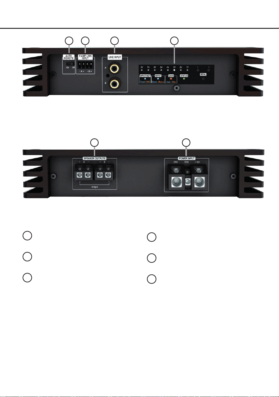
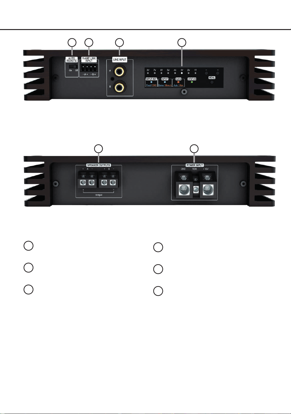
Anschluss- und Bedienelemente
1
3
2
1
Auto Remote-Schalter
Seite 6, Punkt 1
2
V-AMP Link-Eingang
Seite 6, Punkt 3
.
3
Lowlevel-Vorverstärkereingänge
Seite 6, Punkt 2
4
Amplier Control Panel
Seite 5, Abbildung 1
5
Lautsprecherausgänge
Seite 9, Punkt 8
6
Anschluss Stromversorgung & Remote
Seite 6, Punkt 4
4
5 6
5
de
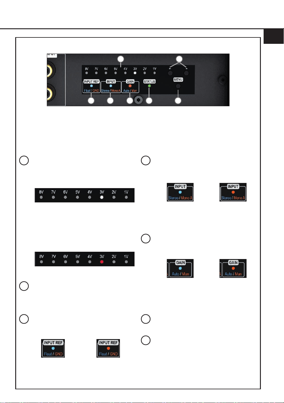
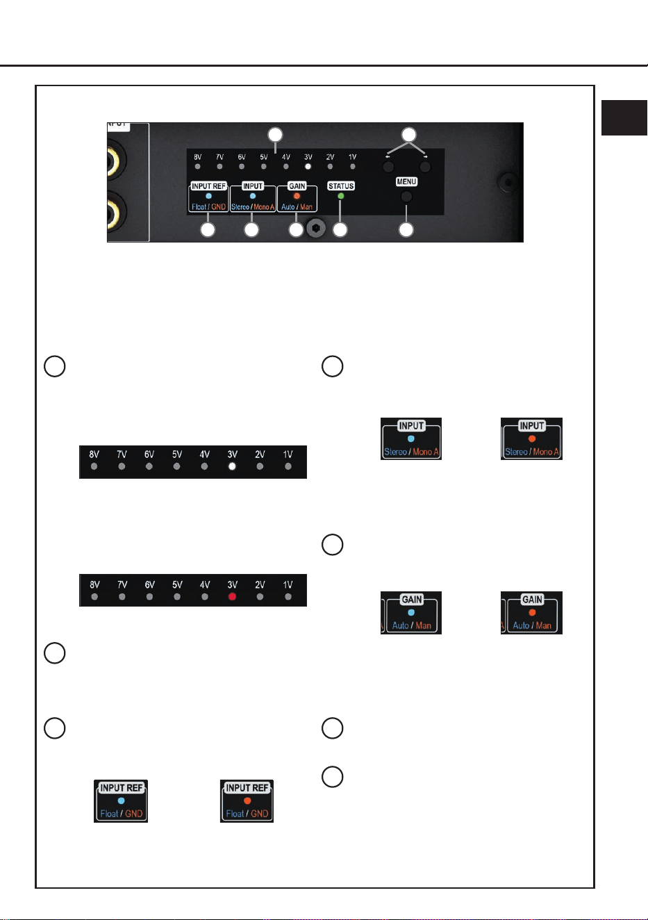
Abb. 1: Amplier Control Panel (ACP)
a
b
c d e g
f
a
Gain- & Clipping-Anzeige
Die LED-Anzeige zeigt den aktuellen Gain-
Wert (im nachfolgenden Bild: 3 Volt) und
dient als Orientierung bei der Einstellung.
Leuchten zwei LEDs gleichzeitig ist ein
Zwischenwert eingestellt, bspw. 3 V und 4 V
entsprechen einem Wert von 3,5 V.
Leuchten eine oder zwei LEDs rot ist der
Signaleingang übersteuert und das Gain
sollte reduziert werden.
Weitere Informationen auf Seite 7, Punkt 7.
b
Pfeiltasten
Die Pfeiltasten dienen zum Umschalten
zwischen den Eigenschaften der
ausgewählten Funktion.
c
Masseanbindung LED (Input Ref)
Diese LED zeigt die gewählte Einstellung
der Masseanbindung der Signalmasse an.
Blau:
Potenzialfreie
Masse
Orange:
Bordnetzmasse
Mehr Informationen: Seite 9, Punkt 9
d
Eingangsmodus LED (Input)
Die LED zeigt den aktuell eingestellten
Eingangsmodus des Verstärkers an.
Blau:
Stereo
Orange:
Mono A
Mehr Informationen: Seite 7, Punkt 6
e
Gain-Modus LED
Zeigt die aktuell ausgewählte Methode zur
Gain-Einstellung an.
Blau:
Auto Gain Ranging
Konguration
Orange:
Manuelle Gain
Konguration
Mehr Informationen: Seite 7, Punkt 7
f
Status LED
Weitere Informationen: Seite 10, Punkt 1
g
Menü-Taste
Die Taste dient zum Aktivieren des Amplier
Control Panels sowie zum Auswählen und
Bestätigen einer Funktion.
Allgemeines zur Funktionsweise:
Ein Druck auf die „Menü“-Taste aktiviert das Amplier Control Panel, weitere Tastendrücke schalten
zwischen den Funktionen. Erfolgt 30 Sekunden lang keine Eingabe, wird die aktuelle Einstellung ge
-
speichert und das Menü verlassen. Das Control Panel wechselt anschließend in den Standby-Modus
(Status-LED aktiv, Gain-Anzeige abgedimmt).

6
Hardware-Konguration
Kongurieren Sie den HELIX V TWO Verstär-
ker in der nachfolgenden Reihenfolge
Achtung: Für die Durchführung der nachfol-
genden Schritte werden Spezialwerkzeuge und
Fachwissen benötigt. Um Anschlussfehler und
Beschädigungen zu vermeiden, fragen Sie im
Zweifelsfall Ihren Einbauspezialisten und beach-
ten Sie zwingend die allgemeinen Anschluss- und
Einbauhinweise (siehe Seite 3).
1. Konguration der Einschaltautomatik
( Auto-Remote)
Diese Einstellung ist nur erforderlich, wenn Sie
einen Verstärker der HELIX V-Serie (V EIGHT
DSP ULTIMATE, V EIGHTEEN DSP etc. am
V-AMP Link Eingang anschließen. Mit dem
„Auto Remote“-Schalter (Seite 4, Punkt 1)
kann die automatische Einschaltung des Ver-
stärkers über den V-AMP Link-Eingang (Sei-
te 4, Punkt 2) ein- oder ausgeschaltet werden.
On (Werkseinstellung): Der Verstärker schal-
tet sich automatisch ein, sobald ein Audio si-
gnal am V-AMP Link-Eingang anliegt.
O: Die automatische Einschaltung über den
V-AMP Link-Eingang ist deaktiviert und erfolgt
ausschließlich über den Remote-Eingang.
Dies sollte vorgenommen werden, wenn es
beispielsweise zu Störgeräuschen beim Ein-
und Ausschalten des Verstärkers kommt.
In diesem Fall muss der Remote-Eingang
( Seite 4, Punkt 6) belegt werden.
2. Anschluss der Vorverstärkereingänge
Die zwei Vorverstärkereingänge (LINE
INPUT) können mit entsprechenden Kabeln
an die RCA / Cinch-Ausgänge der Signalquel-
le (DSP der DSP-Verstärker) angeschlossen
werden. Die Eingangsempndlichkeit kann
mit Hilfe des Amplier Control Panel optimal
an die Ausgangsspannung der Signalquelle
angepasst werden (Seite 7, Punkt 7).
Im Eingangsmodus „Mono A“ (Seite 7,
Punkt 6) muss dabei nur der Kanal A belegt
werden. In diesem wird das Eingangssignal
von Kanal A an beiden Lautsprecherausgän-
gen ausgegeben. Im „Stereo“-Modus wird
jeder der Lautsprecherausgänge mit dem
dazugehörigem Eingangssignal versorgt. Der
aktuell aktivierte Modus wird durch Eingangs-
modus LED am Amplier Control Panel ange-
zeigt (Seite 5, Abb. 1).
Die Einschaltautomatik (Auto Remote) des
Verstärkers funktioniert bei den Vorverstär-
kereingängen nicht, so dass der Remote-Ein-
gang (REM) zwingend belegt werden muss.
Achtung: Der V-AMP Link-Eingang und
der Vorverstärkersignaleingang dürfen nicht
gleichzeitig genutzt werden, da dies zu Schä-
den am Soundsystem führen kann.
3. Anschluss des V-AMP Link-Eingangs
Der V-AMP Link-Eingang ist speziell für den
Anschluss eines Verstärkers der HELIX V-
Serie – beispielsweise des V EIGHT DSP
ULTIMATE – optimiert.
Die zwei Signaleingänge können mit ent-
sprechenden Kabeln (Lautsprecherkabel mit
max. 1 mm² Querschnitt) direkt mit den Laut-
sprecherausgängen des HELIX Verstärkers
verbunden werden.
Die Eingangsempndlichkeit kann mit Hilfe
des Amplier Control Panel optimal an die
Ausgangsspannung der Signalquelle ange-
passt werden (Seite 7, Punkt 7).
Dabei müssen nicht zwingend beide Eingän-
ge belegt werden. Wird nur ein Kanal belegt,
ist Kanal A zu belgen und der Eingangsmodus
auf „Mono A“ zu stellen (Seite 7, Punkt 6). In
diesem wird das Eingangssignal von Kanal A
an beiden Lautsprecherausgängen ausgege-
ben. Im „Stereo“-Modus wird jeder der Laut-
sprecherausgänge mit dem dazugehörigem
Eingangssignal versorgt. Der aktuell aktivierte
Modus wird durch Eingangsmodus LED am
Amplier Control Panel angezeigt (Seite 5,
Abb. 1).
Achtung: Der V-AMP Link-Eingang und
der Vorverstärkersignaleingang dürfen nicht
gleichzeitig genutzt werden, da dies zu Schä-
den am Soundsystem führen kann.
4. Anschluss der Stromversorgung & Remote
Vor dem Anschluss des +12 V
Versorgungskabels an das Bordnetz muss
die Autobatterie abgeklemmt werden.
Achten Sie unbedingt auf eine korrekte Pola-
rität.
+12 V: Anschluss für die Plusleitung.
Das +12 V Stromkabel ist am Pluspol der Bat-

7
de
terie anzuschließen. Die Plusleitung sollte in
einem Abstand von max. 30 cm von der Batte-
rie mit einer Hauptsicherung abgesichert wer-
den. Der Wert der Sicherung errechnet sich
aus der maximalen Stromaufnahme der ge-
samten Car-Hi Anlage (V TWO = max. 86 A).
Verwenden Sie bei kurzen Leitungen (< 1 m)
einen Querschnitt von mindestens 10 mm².
Bei längeren Leitungen empfehlen wir einen
Querschnitt von 16 mm² bis 25 mm².
GND: Anschluss für die Masseleitung. Das
Massekabel muss an einer nicht isolierten
Stelle mit dem Kfz-Chassis oder direkt mit
dem Minuspol der Autobatterie verbunden
werden. Der Kabelquerschnitt sollte den glei-
chen Durchmesser wie die Plusleitung haben.
Ein nicht ausreichender Massekontakt führt
zu unerwünschten Störgeräuschen und Fehl-
funktionen.
REM:
Der Remote-Eingang dient zum Ein-
schalten der
V TWO
, wenn die Vorverstär-
ker-Eingänge (LINE INPUT) genutzt werden
oder der Verstärker bewusst nur über ein
Remote-Signal ein- und ausgeschaltet wer
-
den soll.
Dazu muss der Remote-Eingang
des Verstärkers mit dem Remote-Ausgang
der unmittelbar vorgeschalteten Komponente
(DSP oder DSP-Verstärker), welche das Ein-
gangssignal für die V TWO liefert, verbunden
werden. Es wird dringend davon abgeraten,
den Remote-Eingang des Verstärkers über
das Zündungsplus des Fahrzeugs zu steuern,
um Störgeräusche beim Ein- und Ausschalten
zu vermeiden.
Hinweis: Dieser Eingang muss nicht belegt
werden, wenn der V-AMP Link-Eingang be-
nutzt wird. Wie Sie die automatische Einschal-
tung deaktivieren können, ist auf Seite 6 unter
Punkt 1 „Konguration der Einschaltautoma-
tik“ nachzulesen.
5. Einschalten des Verstärkers
Nachdem Sie die Schritte 1 bis 5 druchgeführt
haben, schalten den Verstärker durch ein-
schalten ihres Soundsystems ein.
6. Konguration des Eingangsmodus
(Mono / Stereo)
Der Verstärker kann sowohl als 1-Kanal (Mo-
no-Modus ) als auch 2-Kanal (Stereo-Modus)
Verstärker betrieben werden.
Der derzeitig aktive Modus wird über die
Eingangsmodus-LED (Seite 5, Punkt d) ange-
zeigt. Werkseitig ist der Stereo-Modus aktiviert.
Stereo (blau): Im Stereo-Modus wird jeder der
Lautsprecherausgänge mit dem dazugehö-
rigem Eingangssignal versorgt.
Mono A (orange): Im Mono-Modus wird das
Eingangssignal von Kanal A an beiden Laut-
sprecherausgängen ausgegeben.
Um zwischen den beiden Modi umzuschalten,
gehen Sie wie folgt vor:
1. Drücken Sie die „Menü“-Taste (Seite 5,
Punkt g), um das Amplier Control Panel
zu aktivieren.
2. Drücken Sie die „Menü“-Taste mehrfach,
bis die Eingangsmodus-LED (Seite 5,
Punkt d) langsam blinkt (Die LED blinkt in
der Farbe des zuletzt kongurierten Mo-
dus; blau oder orange).
3. Mit den Pfeiltasten (Seite 5, Punkt b) wech-
seln Sie nun zwischen den beiden Modi.
Blau: Stereo
Orange: Mono A
4. Drücken Sie erneut die „Menü“-Taste, um
den Vorgang zu beenden.
Hinweis: Wird innerhalb von 30 Sekunden
keine weitere Eingabe vorgenommen, ver-
lässt der Verstärker automatisch das Menü
und speichert den zu diesem Zeitpunkt ak-
tiven Modus.
7. Einstellen der Eingangsempndlichkeit
ACHTUNG: Es ist zwingend notwendig, die
Eingangsempndlichkeit der V TWO an die
Signalquelle anzupassen, um eine bestmög-
liche Signalqualität zu garantieren und Schä-
den am Verstärker zu vermeiden.
Bei der V TWO stehen Ihnen dafür zwei Mög-
lichkeiten über das innovative Amplier Con-
trol Panel (ACP) zur Verfügung:
I: Auto Gain Ranging (AGR) – automatische
Einstellung (empfohlen)
II: Manuelle Gain-Einstellung
Wichtig: Verwenden Sie die manuelle Ein-
stellung nur, wenn Ihnen die maximale Aus-
gangsspannung der Signalquelle bekannt

8
Hardware-Konguration
ist. In allen anderen Fällen empfehlen wir die
automatische Auto Gain Ranging-Funktion,
da sie eine schnelle, präzise und fehlerfreie
Einstellung ermöglicht.
Der Gain-Regelbereiche sind:
Cinch: 0,5 - 8 Volt
V-AMP Link: 1,5 - 21 Volt
Die LEDs der Gain- & Clipping-Anzeige (Sei-
te 5, Punkt a) dienen dabei als Kontrollinstru-
ment.
I: Automatische Gain-Einstellung mit Auto
Gain Ranging (AGR)
ACHTUNG: Wir empfehlen während die-
ser Prozedur keine Lautsprecher an die
Ausgänge anzuschließen. Falls dennoch
Lautsprecher angeschlossen sind, werden
die Lautsprecherausgänge zum Schutz au-
tomatisch deaktiviert.
1. Drücken Sie die „Menü“-Taste (Seite 5,
Punkt g), um das Amplier Control Panel
zu aktivieren.
2. Drücken Sie die „Menü“-Taste erneut, bis
die Gain-Modus LED (Seite 5, Punkt e)
langsam orange blinkt.
3. Starten Sie durch einen langen Druck auf
die „Menü“-Taste die Auto Gain Ranging-
Funktion.
4. Drehen Sie die Lautstärke Ihres Radios
auf 90 % der Gesamtlautstärke und spie-
len Sie ein geeignetes Testsignal, idea-
lerweise unser speziell dafür entwickltes
„IGS - Input Gain Setup“ Signal, welches
Sie unter den „Audio Test Tracks“ des
DSP PC-Tools nden oder auch auf
www.audiotec-scher.de downloaden
können.
Währenddessen zeigt das Lauicht der
Gain- & Clipping-Anzeige den Status des
Eingangssignals an:
Grünes Lauicht: Gültiges Signal erkannt
Rotes Lauicht: Kein gültiges Signal er-
kannt. Überprüfen Sie in diesem Fall Ihre
Signalquelle und den Pegel.
5. Starten Sie die Einmessung durch einen
kurzen Druck auf die „Menü“-Taste.
Der Fortschritt wird durch das Auüllen
der LEDs an der Gain- & Clipping-Anzei-
ge visualisiert.
Möchten Sie die Einmessung abbre-
chen, können Sie dies jederzeit während
des Vorgangs durch langen Druck auf
die „Menü“-Taste tun. Der zuletzt einge-
stellte Gain-Wert wird in diesem Fall au-
tomatisch wiederhergestellt.
Bei erfolgreicher Einmessung: Die LEDs
pulsieren grün.
Bei fehlgeschlagener Einmessung: Die
LEDs pulsieren rot. Mögliche Ursachen:
Eingangssignal kleiner 0,5 V oder Än-
derung der Lautstärke während der Ein-
messung.
6. Beenden Sie die Signalwiedergabe
und reduzieren Sie den Pegel nach Ab-
schluss der Einmessung – unabhängig
vom Ergebnis.
7. Drücken Sie erneut die „Menü“-Taste,
um den Vorgang zu beenden.
Achtung: Hierdurch wird die Stumm-
schaltung der Lautsprecher aufgehoben.
Bei erfolgreicher Einmessung wird der er-
mittelte Gain-Wert gespeichert und durch
ein weißes leuchten angezeigt.
Bei Misserfolg wird automatisch der zuletzt
gültige Gain-Wert wiederhergestellt.
II: Manuelle Gain-Einstellung
ACHTUNG: Schließen Sie während dieser
Prozedur keine Lautsprecher an die Laut-
sprecherausgänge des Verstärkers an.
1. Drücken Sie die „Menü“-Taste (Seite 5,
Punkt g), um das Amplier Control Panel
zu aktivieren.
2. Drücken Sie die „Menü“-Taste erneut, bis
die Gain-Modus LED (Seite 5, Punkt e)
langsam orange blinkt.
3. Drehen Sie die Lautstärke Ihres Radios
auf 90 % der Gesamtlautstärke und spie-
len Sie ein geeignetes Testsignal, idea-
lerweise unser speziell dafür entwickltes
„IGS - Input Gain Setup“ Signal, welches
Sie unter den „Audio Test Tracks“ des
DSP PC-Tools nden oder auch auf
www.audiotec-scher.de downloaden
können.

9
de
4. Im Regelfall leuchten ein oder zwei LEDs
der
Gain- & Clipping-Anzeige
(Seite 5,
Punkt a) weiß.
Sollten eine oder mehrere LEDs be-
reits rot leuchten, ist der Signaleingang
übersteuert. In diesem Fall sollte die
Eingangsempndlichkeit durch Drücken
der linken Pfeiltaste reduziert werden.
Um den Gain-Wert optimal einzustellen,
erhöhen Sie die Eingangsempndlichkeit
schrittweise mit der rechten Pfeiltaste,
bis eine oder zwei LEDs rot aueuchten.
Dieser kurzzeitig übersteuerte Zustand
dient als Referenz für den optimalen Pe-
gel.
5. Drücken Sie anschließend die linke Pfeil-
taste einmal, bis die betroene(n) LED(s)
wieder weiß leuchtet/leuchten.
6. Drücken Sie die „Menü“-Taste, um den
eingestellten Gain-Wert zu bestätigen
und den Vorgang zu beenden. Die LED
des Gain-Modus (Seite 5, Punkt e)
leuchtet nun dauerhaft orange und die
LED der Gain- & Clipping-Anzeige zeigt
den eingestellten Wert in weiß an.
Hinweis: Wird innerhalb von 30 Sekun-
den keine Eingabe vorgenommen, verlässt
der Verstärker automatisch das Menü und
speichert die zu diesem Zeitpunkt gewählte
Gain-Einstellung.
8. Anschluss der Lautsprecherausgänge
Die Lautsprecherausgänge können direkt mit
den Lautsprecherleitungen verbunden wer-
den. Verbinden Sie niemals die Lautsprecher-
leitungen mit der Kfz-Masse (Fahrzeugkaros-
serie). Dieses kann Ihren Verstärker und Ihre
Lautsprecher zerstören.
Achten Sie darauf, dass alle Lautsprecher-
systeme phasenrichtig angeschlossen sind,
d.h. Plus zu Plus und Minus zu Minus. Ver-
tauschen von Plus und Minus hat einen To-
talverlust der Basswiedergabe zur Folge. Der
Pluspol ist bei den meisten Lautsprechern ge-
kennzeichnet.
Die Impedanz pro Kanal darf im Stereo-Mo-
dus 2 Ohm und im Mono-Modus 2 x 2 Ohm /
gebrückt 1 x 4 Ohm nicht unterschreiten, da
sonst die Schutzschaltung des Verstärkers
aktiviert wird.
Beispiele für den Lautsprecheranschluss n-
den Sie auf Seite 11 f.
9. Optional: Konguration der Masseanbin-
dung
In bestimmten Fällen kann es notwendig sein,
die Signalmasse der Signaleingänge anzu-
passen. Dies geschieht über das Amplier
Control Panel (Seite 5, Abb. 1).
Float (blau): Die Signalmasse ist durch einen
Dierenzverstärker von der Bordnetzmasse
getrennt.
Dies ist in den meisten Fahrzeugen die opti-
male Einstellung, um Störgeräusche, wie z. B.
von der Lichtmaschine, zu vermeiden.
GND (orange): Die Signalmasse des Ein-
gangs wird direkt mit der Bordnetzmasse
verbunden. Diese Einstellung sollte gewählt
werden, wenn bei der Einstellung „Float“ Stör-
geräusche auftreten.
Um zwischen den beiden Modi umzuschalten,
gehen Sie wie folgt vor:
1. Drücken Sie die „Menü“-Taste (Seite 5,
Punkt g), um das Amplier Control Panel
zu aktivieren.
2. Drücken Sie die „Menü“-Taste erneut
mehrfach, bis die LED der Masseanbin-
dungsfunktion „Input Ref“ (Seite 5, Punkt c)
langsam blinkt (Die LED blinkt in der Farbe
der zuletzt gewählten Einstellung: blau für
Float, orange für GND).
3. Verwenden Sie die Pfeiltasten (Seite 5,
Punkt b), um zwischen den beiden Modi zu
wechseln:
Blau: Float
Orange: GND
4. Bestätigen Sie die Auswahl durch einen
weiteren Druck auf die „Menü“-Taste.
Die LED der Masseanbindungsfunktion
zeigt nun die gewählte Konguration an:
blau (Float) oder orange (GND).
Hinweis: Wird innerhalb von 30 Sekun-
den keine Eingabe vorgenommen, verlässt
der Verstärker automatisch das Menü und
speichert die zu diesem Zeitpunkt gewählte
Einstellung.

10
1. Status LED
Die Status LED (Seite 5, Punkt f) zeigt den
Betriebszustand des Verstärkers an.
Grün blinkend: Startvorgang des Verstärkers.
Grün: Verstärker eingeschaltet und betriebsbe-
reit.
Orange schnell blinkend: Sicherung im Inne-
ren des Geräts zerstört. Prüfen Sie die Siche-
rungen im Gerät und tauschen diese gegebe-
nenfalls aus. Die Sicherungen im Verstärker
dürfen nur mit den gleichen Werten (3 x 30 A)
ersetzt werden, um eine Beschädigung des
Gerätes zu verhindern. Höhere Werte können
zu gefährlichen Folgeschäden führen.
Orange: Protection Mode aktiv. Dieser kann
durch folgende Ursachen ausgelöst werden:
1. Unterspannung: Die Eingangsspannung
des Verstärkers liegt dauerhaft unter
10,5 Volt. Kurzfristige Einbrüche bis auf 6
Volt sind zulässig und aktivieren nicht den
Unterspannungsschutz.
2. Überspannung: Die Eingangsspannung
des Verstärkers überschreitet 18 Volt.
3. Lautsprecherimpedanz zu niedrig: Siehe-
Seite 9, Punkt 8. Sollte sich der Verstär-
ker nach Beseitigung der Fehlerquelle
nicht wieder einschalten lassen, liegt ein
Defekt vor und muss zur Reparatur einge-
schickt werden. Wenden Sie sich hierzu
an einen autorisierten HELIX Händler vor
Ort.
Rot: Protection Mode aktiv. Protection Mode
aktiv. Die Temperatur des Verstärkers liegt
über 85°C. Die interne Temperaturüberwa-
chung schaltet das Gerät ab, bis ein sicherer
Betrieb wieder gewährleistet werden kann.
Weitere Funktionen
11
de
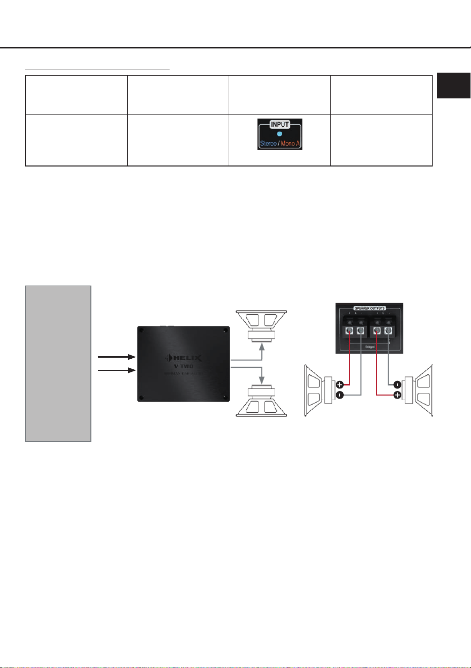
Kongurationshinweise Eingangsmodus Stereo:
Modus
Verstärker-
Eingang
Eingangsmodus
(Input)
Min. Impedanz
pro Lautsprecher
Stereo
(2-Kanal)
Line Input A & B
oder
V-AMP LINK A & B
LED: Blau
2 Ω
Wichtig: Die Übernahmefrequenzen für den Hoch- bzw. Tiefpass müssen im vorgeschalteten DSP /
DSP-Verstärker eingestellt werden.
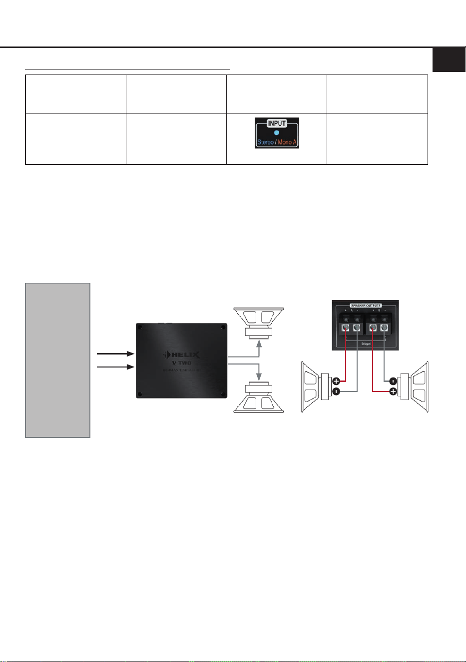
Kongurationsbeispiele Stereo Mode
Beispiel 1: 2-Kanal Tiefton-Anwendung
Zwei Tiefmitteltonlautsprecher oder zwei Subwoofer mit einer Schwingspule
Subwoofer LSubwoofer R
A
Tiefmitteltöner
oder
Subwoofer R
Tiefmitteltöner
oder
Subwoofer L
B
A
B
! Min. Impedanz pro Lautsprecher 2 Ω !
DSP / DSP-
Verstärker via
Cinch
oder
HELIX V-Serien
Verstärker via
V-AMP Link
12
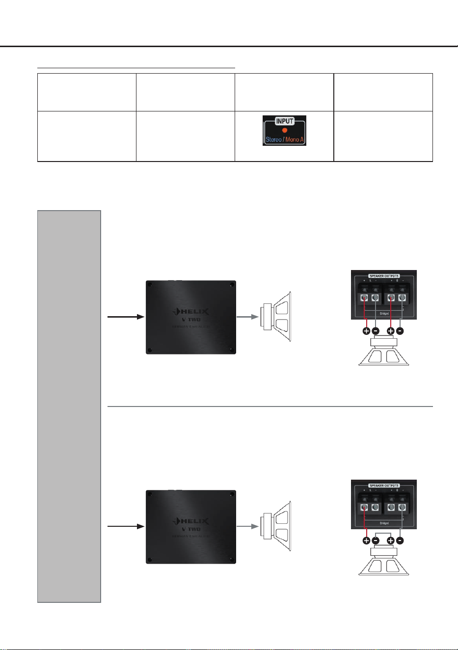
Kongurationsbeispiele Mono Mode
DSP / DSP-
Verstärker via
Cinch
oder
HELIX V-Serien
Verstärker via
V-AMP Link
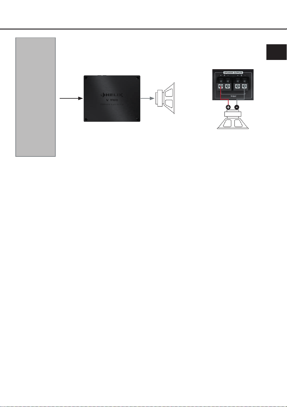
Beispiel 3: 1-Kanal Subwoofer-Anwendung
Beispiel 2: 1-Kanal Subwoofer-Anwendung
Subwoofer mit Doppelschwingspule
SW = Schwingspule
! Min. Impedanz 2 x 2 Ω !
SW 2 SW 1
Subwoofer
A
A
Kongurationshinweise Eingangsmodus Mono:
Modus
Verstärker-
Eingang
Eingangsmodus
(Input)
Min. Impedanz
pro Lautsprecher
Mono A
(1-Kanal)
Line Input A
oder
V-AMP LINK A
LED: Orange
Gebrückt: 4 Ω
Stereo: 2 Ω
Wichtig: Die Übernahmefrequenzen für den Hoch- bzw. Tiefpass müssen im vorgeschalteten DSP /
DSP-Verstärker eingestellt werden.
Subwoofer mit Doppelschwingspule in Reihenschaltung
SW = Schwingspule
! Min. Impedanz 2 x 2 Ω !
Daraus ergibt sich eine min.
Gesamtimpedanz von 4 Ω
SW 2 SW 1
Subwoofer
A
A
13
de
Technische Daten
Leistung RMS (≤ 1% THD+N)
- @ 4 Ohm .................................................................... 2 x 200 Watt
- @ 2 Ohm .................................................................... 2 x 400 Watt
- gebrückt @ 4 Ohm .....................................................1 x 800 Watt
Max. Leistung pro Kanal* ............................................. Bis zu 500 Watt RMS @ 2 Ohm
Bis zu 1000 Watt RMS @ 4 Ohm gebrückt
Verstärkertechnologie ...................................................Class D
Eingänge ...................................................................... 2 x Cinch
2 x V-AMP Link
1 x Remote In
Eingangsempndlichkeit ............................................... Cinch: 0,5 - 8 Volt
V-AMP Link: 1,5 - 21 Volt
Eingangsimpedanz ....................................................... Cinch: 3 kOhm
V-AMP Link: 13 Ohm
Ausgänge ..................................................................... 2 x Lautsprecherausgang
Frequenzbereich...........................................................10 Hz - 22.000 Hz
Signal- / Rauschabstand (A-bewertet)..........................109 dB
Klirrfaktor (THD @ 1 kHz, 1 W an 4 Ohm) ...................< 0,003 %
Klirrfaktor (THD+N @ 1 kHz, 1 W an 4 Ohm) ...............< 0,004 %
Dämpfungsfaktor ..........................................................350
Betriebsspannung.........................................................10,5 - 18 Volt (max. 5 Sek. bis hinab zu 6 Volt)
Leerlaufstromaufnahme................................................1.400 mA
Sicherung .....................................................................3 x 30 A LP-Mini-Stecksicherung
Leistungsaufnahme ......................................................DC 12 V 86 A max.
Umgebungstemperaturbereich für den Betrieb ............-40 °C bis +70 °C
Zusätzliche Features .................................................... Auto-Gain-Ranging, Mono / Stereo Modus,
Start-Stopfähigkeit, V-AMP Link, geregeltes
Netzteil
Abmessungen (H x B x T) ............................................44 x 220 x 180 mm
* In typischen Anwenudungen als Subwoofer-Verstärker
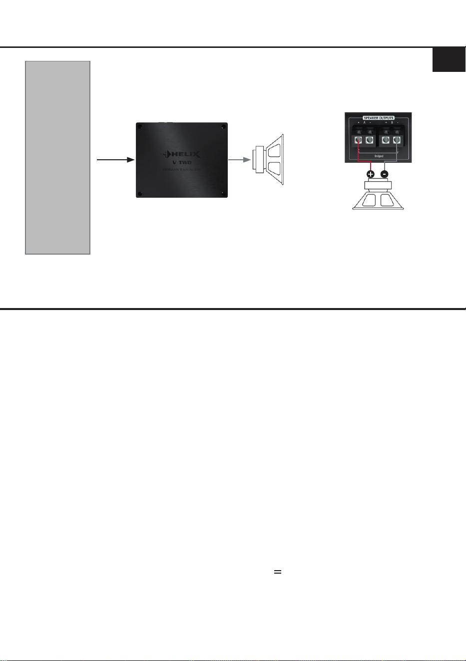
DSP / DSP-
Verstärker via
Cinch
oder
HELIX V-Serien
Verstärker via
V-AMP Link
Beispiel 4: 1-Kanal Subwoofer-Anwendung
Subwoofer mit einer Schwingspule
Subwoofer
A
A
! Min. Gesamtimpedanz 4 Ω !
14
Die Garantieleistung entspricht der gesetzlichen Regelung. Von der Garantieleistung ausgeschlossen
sind Defekte und Schäden, die durch Überlastung oder unsachgemäße Behandlung entstanden sind.
Eine Rücksendung kann nur nach vorheriger Absprache in der Originalverpackung, einer detaillierten
Fehlerbeschreibung und einem gültigen Kaufbeleg erfolgen. Technische Änderungen, Druckfehler und
Irrtümer vorbehalten!
Für Schäden am Fahrzeug oder Gerätedefekte, hervorgerufen durch Bedienungsfehler des Gerätes,
können wir keine Haftung übernehmen.
Garantiehinweis
Dieses Produkt ist mit einer CE-Kennzeichnung versehen. Damit ist das Gerät für den Be-
trieb in Fahrzeugen innerhalb der Europäischen Union (EU) zertiziert.
Dieses Symbol bedeutet, dass das Produkt nicht über den Hausmüll entsorgt werden darf,
sondern bei einer entsprechenden Sammelstelle zum Recycling abgegeben werden muss.
Befolgen Sie die örtlichen Vorschriften und entsorgen Sie das Produkt niemals mit dem nor-
malen Hausmüll. Die ordnungsgemäße Entsorgung von Altgeräten trägt zur Vermeidung
von Umwelt- und Gesundheitschäden bei.
Dieses Produkt ist mit einer UKCA-Kennzeichnung versehen. Damit ist das Gerät für den
Betrieb in Fahrzeugen innerhalb des Vereinigten Königreichs zertiziert.
Dieses Produkt ist mit einer EAC-Kennzeichnung versehen. Damit ist das Gerät für den
Betrieb in Fahrzeugen innerhalb der Eurasian Customs Union zertiziert.
Hinweise zur Entsorgung
Regulatorische Hinweise

15
General installation instructions for HELIX
components
To prevent damage to the unit and possible injury,
read this manual carefully and follow all installa-
tion instructions. This product has been checked
for proper function prior to shipping and is guaran-
teed against manufacturing defects.
Before starting your installation, disconnect
the battery’s negative terminal to prevent
damage to the unit, re and / or risk of injury.
For a proper performance and to ensure full war-
ranty coverage, we strongly recommend to get this
product installed by an authorized HELIX dealer.
Install your HELIX V TWO in a dry location with
sucient air circulation for proper cooling of the
equipment. The amplier should be secured to
a solid mounting surface using proper mounting
hardware. Before mounting, carefully examine the
area around and behind the proposed installation
location to insure that there are no electrical ca-
bles or components, hydraulic brake lines or any
part of the fuel tank located behind the mounting
surface. Failure to do so may result in unpredict-
able damage to these components and possible
costly repairs to the vehicle.
General instruction for connecting the HELIX
V TWO amplier
The HELIX V TWO amplier may only be installed
in vehicles which have a 12 Volts negative termi-
nal connected to the chassis ground. Any other
system could cause damage to the amplier and
the electrical system of the vehicle.
The positive cable from the battery for the com-
plete system should be provided with a main fuse
at a distance of max. 30 cm from the battery. The
value of the fuse is calculated from the maximum
total current input of the car audio system.
Use only suitable cables with sucient cable
cross section for the connection of the HELIX
V TWO. The fuses may only be replaced by
identically rated fuses (3 x 30 A) to avoid dam-
age of the amplier.
Prior to installation, plan the wire routing to
avoid any possible damage to the wire harness.
All cabling should be protected against possible
crushing or pinching hazards. Also avoid routing
cables close to potential noise sources such as
electric motors, high power accessories and other
vehicle harnesses.
Congratulations!
General instructions
Dear Customer,
Congratulations on your purchase of this innova-
tive and high-qual ity HELIX product.
Thanks to more than 35 years of experience in
research and development of audio products this
amplier sets new standards in the range of am-
pliers.
We wish you many hours of enjoyment with your
new HELIX V TWO.
Yours,
AUDIOTEC FISCHER
en
16
Connectors and control units
1
3
2
1
Auto remote switch
Page 18, point 1
2
V-AMP Link input
Page 18, point 3
.
3
Lowlevel line inputs
Page 18, point 2
4
Amplier Control Panel
Page 17, gure 1
5
Speaker outputs
Page 21, point 8
6
Power & Remote connector
Page 18, point 4
4
5 6
17
en
Fig. 1: Amplier Control Panel (ACP)
a
b
c d e g
f
a
Gain & Clipping indicator
The LED display shows the current gain
value (in the image below: 3 Volts) and
serves as a visual reference during
adjustment.
Two lit LEDs indicate an intermediate
value (e.g. 3 V and 4 V = 3.5 V).
If one or two LEDs light up red, the input
signal is overdriven and the gain should be
reduced.
For more information, see page 19, point 7.
b
Arrow buttons
The arrow buttons are used to toggle
between the properties of the selected
function.
c
Input reference LED
This LED shows the congured input ground
reference of the signal ground.
More information: page 21, point 9
Blue:
Floating ground
Orange:
Vehicle ground
d
Input mode LED
The LED indicates the currently selected
input mode of the amplier.
More information: page 19, point 6
e
Gain setting mode LED
Indicates the currently selected method for
gain adjustment.
More information: page 19, point 7
f
Status LED
More information: page 22, point 1
g
Menu pushbutton
This pushbutton is used to activate the
Amplier Control Panel, as well as to select
and conrm a function.
Blue:
Stereo
Orange:
Mono A
Blau:
Auto Gain Ranging
conguration
Orange:
Manual gain
conguration
General functionality:
Pressing the “Menu” button activates the Amplier Control Panel; additional presses cycle through the
available functions. If no input is made for 30 seconds, the current setting is saved and the menu is
exited. The control panel then switches to standby mode (status LED remains active, gain display is
dimmed).

18
Hardware conguration
Congure the HELIX V TWO as follows
Caution: Carrying out the following steps will re-
quire special tools and technical knowledge. In or-
der to avoid connection mistakes and / or damage,
ask your dealer for assistance if you have any
questions and follow all instructions in this manual
(see page 15). It is recommended that this unit will
be installed by an authorized HELIX dealer.
1. Conguration of the automtic turn-on
(Auto Remote)
This setting is only required when connecting
a HELIX V series amplier (e.g., V EIGHT
DSP ULTIMATE, V EIGHTEEN DSP etc.) to
the V TWO´s V-AMP Link input.
The automatic turn-on feature via the V-AMP
Link input can be enabled or disabled using
the “Auto Remote” switch (page 16, point 1).
The feature should be deactivated if there are
e.g. noises while switching on / o the ampli-
er.
On (by default): The amplier turns on auto-
matically as soon as an audio signal is detect-
ed at the V-AMP Link input.
O: Automatic turn-on via the V-AMP Link in-
put is disabled. In this case, the amplier must
be switched on via the remote input (Page 16,
point 6).
2. Connecting the line inputs
These two lowlevel line inputs can be con-
nected to signal sources such as DSPs or
DSP ampliers using appropriate cables. It is
possible to optimally adapt the input sensitivity
to the signal source using the amplier control
panel (page 19, point 7).
It is not mandatory to use both line input
channels. In “Mono A” input mode (page 19,
point 6) only input channel A needs to be con-
nected. In this case the input signal of channel
A is supplied to both output channels. In “Ste-
reo” mode, each speaker output is supplied
with its respective input signal. The currently
active mode is indicated by the Input Mode
LED on the Amplier Control Panel (page 17,
g. 1).
The automatic turn-on circuit does not work
when using the line inputs. In this case the
remote input (REM) has to be connected to
activate the HELIX TWO.
Important: The V-AMP Link input and the
lowlevel line input must not be used at the
same time, as this may cause damage to the
sound system.
3. Connecting the V-AMP Link input
The V-AMP Link input is specially optimized
for connecting a HELIX V Series amplier,
such as the V EIGHT DSP ULTIMATE.
The two signal inputs can be connected di-
rectly to the speaker outputs of the HELIX am-
plier using appropriate cables (loudspeaker
cables with 1 mm² / AWG 18 max.).
The input sensitivity can be optimally adjust-
ed to the output voltage of the signal source
using the Amplier Control Panel (page 19,
point 7).
It is not mandatory to use both input channels.
In “Mono A” (page 19, point 6) input mode
only input channel A needs to be connected.
In this case the input signal of channel A is
supplied to both output channels. In “Stereo”
mode, each speaker output is supplied with its
respective input signal. The currently active
mode is indicated by the Input Mode LED on
the Amplier Control Panel (page 17, g. 1).
Important: The V-AMP Link input and the
lowlevel line input must not be used at the
same time, as this may cause damage to the
sound system.
4. Connection to power supply & remote
Make sure to disconnect the battery before
installing the V TWO.
Ensure correct polarity.
+12 V: Connector for the positive cable.
Connect the +12 V power cable to the posi-
tive terminal of the battery. The positive wire
from the battery to the ampliers power termi-
nal needs to have an inline fuse at a distance
of no more than 12 inches (30 cm) from the
battery. The value of the fuse is calculated
from the maximum total current input of the
whole car audio system (V TWO = max. 86 A).
If your power wires are short (less than 1 m /
40”) then a wire gauge of 10 mm² / AWG 8
will be sucient. In all other cases we strong-
ly recommend gauges of 16 - 25 mm² / AWG
6 – 4!

19
en
GND: Connector for the ground cable. The
ground wire should be connected to a com-
mon ground reference point (this is located
where the negative terminal of the battery is
grounded to the metal body of the vehicle) or
to a prepared metal location on the vehicle
chassis, i.e., an area cleaned of all paint resi-
dues. The cable should have the same gauge
as the +12 V wire. Inadequate grounding
causes audible interference and malfunctions.
REM: The remote input is used to power on
the V TWO when the line inputs are used,
or when the amplier should be deliberately
switched on and o via a remote signal. In
these cases, this input must be connected.
The remote wire should be connected to the
remote output of the
preconnected device
(DSP or DSP amplier) that supplies the input
signal to the V TWO
.
We do not recommend controlling the remote
input via the ignition switch to avoid pop noise
during turn on / o.
Note: This input does not need to be connect-
ed if the V-AMP Link input is used. To deacti-
vate the “automatic turn-on” function read the
description on page 18, point 1 “Conguration
of the automatic turn-on (Auto Remote)”.
5. Powering on the amplier
After completing steps 1 to 5, switch on the
amplier by powering on your audio system.
6. Adjusting the input mode (Mono / Stereo)
The amplier can be operated either as a
1-channel (mono) or 2-channel (stereo) am-
plier.
The currently active mode is indicated by the
input mode LED (page 17, point d).
The default factory setting is “Stereo” mode.
Stereo (blue): In stereo mode, each speaker
output is supplied with its corresponding input
signal.
Mono A (orange): In mono mode the input sig-
nal from channel A is routed to both speaker
outputs
To switch between the two modes, proceed as
follows:
1. Press the “Menu” button (page 17, point g)
to activate the Amplier Control Panel.
2. Press the “Menu” button repeatedly un-
til the input mode LED (page 17, item d)
ashes slowly (the LED ashes in the color
of the last selected mode: blue or orange).
3. Use the arrow buttons (page 17, point b) to
toggle between the two modes:
Blue: Stereo
Orange: Mono A
4. Press the “Menu” button again to complete
the process.
Note: If no input is made within 30 seconds,
the amplier automatically exits the menu and
saves the currently active mode.
7. Adjustment of the input sensitivity
ATTENTION: It is mandatory to properly
adapt the input sensitivity of the V TWO to the
signal source to achieve the best possible sig-
nal quality and avoid damage to the amplier.
The V TWO oers two options for gain ad-
justment via the innovative Amplier Control
Panel (ACP):
I: Auto Gain Ranging (AGR) – automatic ad-
justment (recommended)
II: Manual gain adjustment
Important: Use manual gain adjustment only
if you know the maximum output voltage of the
connected signal source.
In all other cases, we recommend using the
Auto Gain Ranging function, which ensures
quick, precise, and reliable setup.
The gain control ranges are:
RCA / Cinch: 0.5 - 8 Volts
V-AMP Link: 1.5 - 21 Volts
The Gain & Clipping indicator (page 17,
point a) provides visual feedback throughout
the process.
I: Automatic gain adjustment using Auto
Gain Ranging (AGR)
ATTENTION: We do not recommend con-
necting any speakers to the outputs during
this procedure. If speakers are connected,
the outputs will be automatically deactivat-
ed to protect the speakers.

20
Hardware conguration
1. Press the “Menu” button (page 17,
point g) to activate the Amplier Control
Panel.
2. Press the “Menu” button repeatedly un-
til the gain setting mode LED (page 17,
point e) ashes slowly in orange.
3. Start the Auto Gain Ranging function by
briey pressing and holding the ‘Menu’
button. To prevent speaker damage, the
amplier automatically mutes its outputs
during the adjustment process.
4. Adjust the volume of your radio to ap-
prox. 90 % of the maximum volume and
play back a suitable test signal – ideally
our proprietary “IGS – Input Gain Setup”
signal, which can be found under “Audio
Test Tracks” in the DSP PC-Tool or down-
loaded from www.audiotec-scher.com.
The running light of the Gain & Clipping
indicator indicates signal detection sta-
tus:
Green running light: Valid signal detected
Red running light: No valid signal de-
tected – in this case, check your signal
source and output level.
5. Start the measurement by pressing the
“Menu” button briey.
Progress is indicated by the lling of the
Gain & Clipping indicator LEDs.
You may cancel the process at any time
by pressing and holding the “Menu” but-
ton. In this case the previously stored
gain value will be restored.
Successful calibration: LEDs pulse
green.
Failed calibration: LEDs pulse red. Pos-
sible reasons: signal level below 0.5 V or
volume changes during calibration.
6. After the measurement (regardless of the
outcome), stop playback and reduce the
volume level.
7. Press the “Menu” button again to com-
plete the process.
Caution: This will deactivate the speaker
mute function.
If the measurement is successful, the deter-
mined gain value is saved and indicated by
white illumination; otherwise, the previous
setting is automatically restored.
II: Manual gain adjustment
ATTENTION: Don‘t connect any loud-
speakers to the outputs of the amplier
during this setup.
1. Press the “Menu” button (page 17,
point g) to activate the Amplier Control
Panel.
2. Press the “Menu” button repeatedly un-
til the gain setting mode LED (page 17,
item e) ashes slowly in orange.
3. Adjust the volume of your radio to ap-
prox. 90 % of the maximum volume and
play back a suitable test signal – ideally
our proprietary “IGS – Input Gain Setup”
signal, which can be found under “Audio
Test Tracks” in the DSP PC-Tool or down-
loaded from www.audiotec-scher.com.
4. Normally, one or two LEDs of the Gain &
Clipping indicator (page 17, point a) light
up white. If one or more LEDs are al-
ready red, the input signal is overdriven.
In this case, the input sensitivity should
be reduced by pressing the left arrow
button.
To optimally set the gain level, gradually
increase the input sensitivity using the
right arrow button until one or two LEDs
light up red. This briey overdriven state
serves as a reference point for the opti-
mal input level.
5. Then press the left arrow button once to
reduce the gain, so that the correspond-
ing LED(s) turn white again.
6. Press the “Menu” button to conrm the
selected gain value and complete the
process.
The gain setting mode LED (page 17,
point e) will now light up solid orange and
the Gain & Clipping indicator will indicate
the stored value in white.
Note: If no input is made within 30 sec-
onds, the amplier automatically exits the
menu and saves the currently selected gain
setting.

21
en
8. Connecting the loudspeaker outputs
The loudspeaker outputs can be connected
directly to the wires of the loudspeakers.
Never connect any of the loudspeaker cables
with the chassis ground as this will damage
your amplier and your speakers. Ensure that
the loudspeakers are correctly connected (in
phase), i.e. plus to plus and minus to minus.
Exchanging plus and minus causes a total
loss of bass reproduction. The plus pole is in-
dicated on most speakers.
The impedance per channel must not be
lower than 2 Ohms in “Stereo” mode and
2 x 2 Ohms / bridged 1 x 4 Ohms in “Mono A”
mode, otherwise the amplier protection will
be activated.
Examples of speaker congurations can be
found on page 23 f.
9. Optional: Conguration of the input refer-
ence (Input Ref)
In some cases, it may be necessary to adjust
the signal ground of the signal inputs.
This can be done using the Amplier Control
Panel (page 17, g.1)
Float (blue): The signal ground is separated
from the vehicle’s ground by a dierential am-
plier. This is usually the best setting in most
vehicles to prevent interference noise, e.g.
from the alternator.
GND (orange): The signal ground is tied to-
gether with the vehicle’s ground. This setting
should be selected if noise occurs in “Float”
mode.
To switch between the two modes, proceed as
follows:
1. Press the “Menu” button (page 17, point g)
to activate the Amplier Control Panel.
2. Press the “Menu” button repeatedly until
the input reference LED (page 17, point c)
ashes slowly. (The LED ashes in the col-
or of the last selected mode: blue for Float,
orange for GND).
3. Use the arrow buttons (page 17, point b) to
toggle between the two modes:
Blue: Float
Orange: GND
4. Conrm the selection by pressing the
“Menu” button once more.
The Input Ref LED will now indicate the se-
lected conguration: blue for Float, orange
for GND.
Note: If no input is made within 30 sec-
onds, the amplier automatically exits the
menu and saves the currently selected gain
setting.

22
Additional functions
1. Status LED
The Status LED (page 17, point f) indicates
the operating mode of the amplier.
Green ashing: Amplier startup in progress.
Green: Amplier is ready for operation.
Orange fast ashing: The internal fuses are
blown. Check the fuses inside the device and
replace them if necessary. The fuses should
only be replaced with ones of the same rating
(3 x 30 A) to prevent damage to the device.
Using higher-rated fuses can lead to danger-
ous consequences.
Orange: Protection mode is active. This may
have dierent root causes:
1. Undervoltage: The input voltage of the
amplier is continuously below 10.5 Volts.
Short-term drops down to 6 Volts are per-
missible and do not activate the under-
voltage protection.
2. Overvoltage: The input voltage of the am-
plier exceeds 18 Volts.
3. Speaker impedance too low: see page 21,
point 8. If the amplier does not turn on, it
is defective and needs to be sent to your
local authorized HELIX dealer for repair
service.
Red: Protection mode is active. The tem-
perature of the amplier exceeds 85°C. The
internal temperature protection shuts down
the device until it reaches a safe temperature
level again.
23
en
Conguration notes stereo mode:
Mode Amplier input
Input mode
(Input)
Min. impedance
per speaker
Stereo
(2-channel)
Line Input A & B
or
V-AMP LINK A & B
LED: Blue
2 Ω
Attention: The crossover frequencies for the high- and lowpass must be set in the preconnected DSP /
DSP amplier.
Conguration examples stereo mode
Example 1: 2-channel woofer application
Two woofers or two subwoofers with single voice coil
Subwoofer LSubwoofer R
A
Woofer
or
subwoofer R
Woofer
or
subwoofer L
B
A
B
! Min. Impedance per speaker 2 Ω !
DSP / DSP
amplier via
RCA / Cinch
or
HELIX V series
amplier via
V-AMP Link

24
Conguration examples mono mode
DSP / DSP
amplier via
RCA / Cinch
or
HELIX V series
amplier via
V-AMP Link
Example 3: 1-channel subwoofer application
Example 2: 1-channel subwoofer application
Subwoofer with dual voice coil
VC = voice coil
! Min. impedance 2 x 2 Ω !
VC 2 VC 1
Subwoofer
A
A
Conguration notes momo mode:
Mode Amplier input
Input mode
(Input)
Min. impedance
per speaker
Mono A
(1-channel)
Line Input A
or
V-AMP LINK A
LED: Orange
Bridged: 4 Ω
Stereo: 2 Ω
Attention: The crossover frequencies for the high- and lowpass must be set in the preconnected DSP /
DSP amplier.
Subwoofer with dual voice coil in series connection
VC = voice coil
! Min. impedance 2 x 2 Ω !
This results in a min. total
impedance of 4 Ω
VC 2 VC 1
Subwoofer
A
A
25
en
DSP / DSP
amplier via
RCA / Cinch
or
HELIX V series
amplier via
V-AMP Link
Example 4: 1-channel subwoofer application
Subwoofer with single voice coil
Subwoofer
A
A
! Min. total impedance 4 Ω !

26
Technical data
Output power RMS (≤ 1% THD+N)
- @ 4 Ohms ..................................................................2 x 200 Watts
- @ 2 Ohms ..................................................................2 x 400 Watts
- bridged @ 4 Ohms .....................................................1 x 800 Watts
Max. output power per channel* ................................... Up to 500 Watts RMS @ 2 Ohms
Up to 1000 Watts RMS @ 4 Ohms bridged
Amplier technology .....................................................Class D
Inputs ............................................................................ 2 x RCA / Cinch
2 x V-AMP Link
1 x Remote In
Input sensitivity ............................................................. RCA / Cinch: 0.5 - 8 Volts
V-AMP Link: 1.5 - 21 Volts
Input impedance ........................................................... RCA / Cinch: 3 kOhms
V-AMP Link: 13 Ohms
Outputs ......................................................................... 2 x Speaker output
Frequency response .....................................................10 Hz - 22,000 Hz
Signal-to-noise ratio (A-weighted) ................................109 dB
Distortion (THD @ 1 kHz, 1 W into 4 Ohms) ................ < 0.003 %
Distortion (THD+N @ 1 kHz, 1 W into 4 Ohms) ...........< 0.004 %
Damping factor .............................................................350
Operating voltage .........................................................10.5 - 18 Volts (max. 5 sec. down to 6 Volts)
Idle current....................................................................1,400 mA
Fuse..............................................................................3 x 30 A LP-Mini-fuse (APS)
Power rating .................................................................DC 12 V 86 A max.
Ambient operating temperature range ..........................-40 °C to +70 °C
Additional features ........................................................ Auto-Gain-Ranging, Mono / Stereo Mode, Start-
Stop capability, V-AMP Link, regulated power
supply
Dimensions (H x W x D) ...............................................44 x 220 x 180 mm / 1.73 x 8.66 x 7.09”
* In typical applications as subwoofer amplier
27
en
The warranty service is based on the statutory regulations. Defects and damage caused by overload
or improper handling are excluded from the warranty service. Any return can only take place following
prior consultation, in the original packaging together with a detailed description of the error and a valid
proof of purchase.
Technical modications, misprints and errors excepted! For damages on the vehicle and the device,
caused by handling errors of the device, we can’t assume liability.
Warranty disclaimer
This product has been issued a CE marking. This means that the device is certied for use
in vehicles within the European Union (EU).
This symbol means the product must not be discarded as household waste, and should
be delivered to an appropriate collection facility for recycling. Follow local rules and never
dispose of the product with normal household waste. Correct disposal of old products helps
prevent negative consequences for the environment and human health.
This product has been issued an UKCA marking. This means that the device is certied for
use in vehicles within the United Kingdom.
This product has been issued an EAC marking. This means that the device is certied for
use in vehicles within the Eurasian Customs Union.
Correct disposal of this product
Regular notes

Audiotec Fischer GmbH
Hünegräben 26 - 28 · 57392 Schmallenberg · Germany
Tel.: +49 2972 9788 0 · Fax: +49 2972 9788 88
E-mail: helix@audiotec-scher.com · Internet: www.audiotec-scher.com
Made in China