EN
EP.V.35874.00 | 12.2023
EP.V.35857.00 | 12.2023
USER MANUAL
Safety storage cabinets for storage
and charging of lithium ion batteries
2
EN
IO90.195.120.PC.WDC IO90.195.120.PS.WDC
IO90.195.060.CC.WDC IO90.195.120.CS.WDC IO90.195.060.CS.WDC
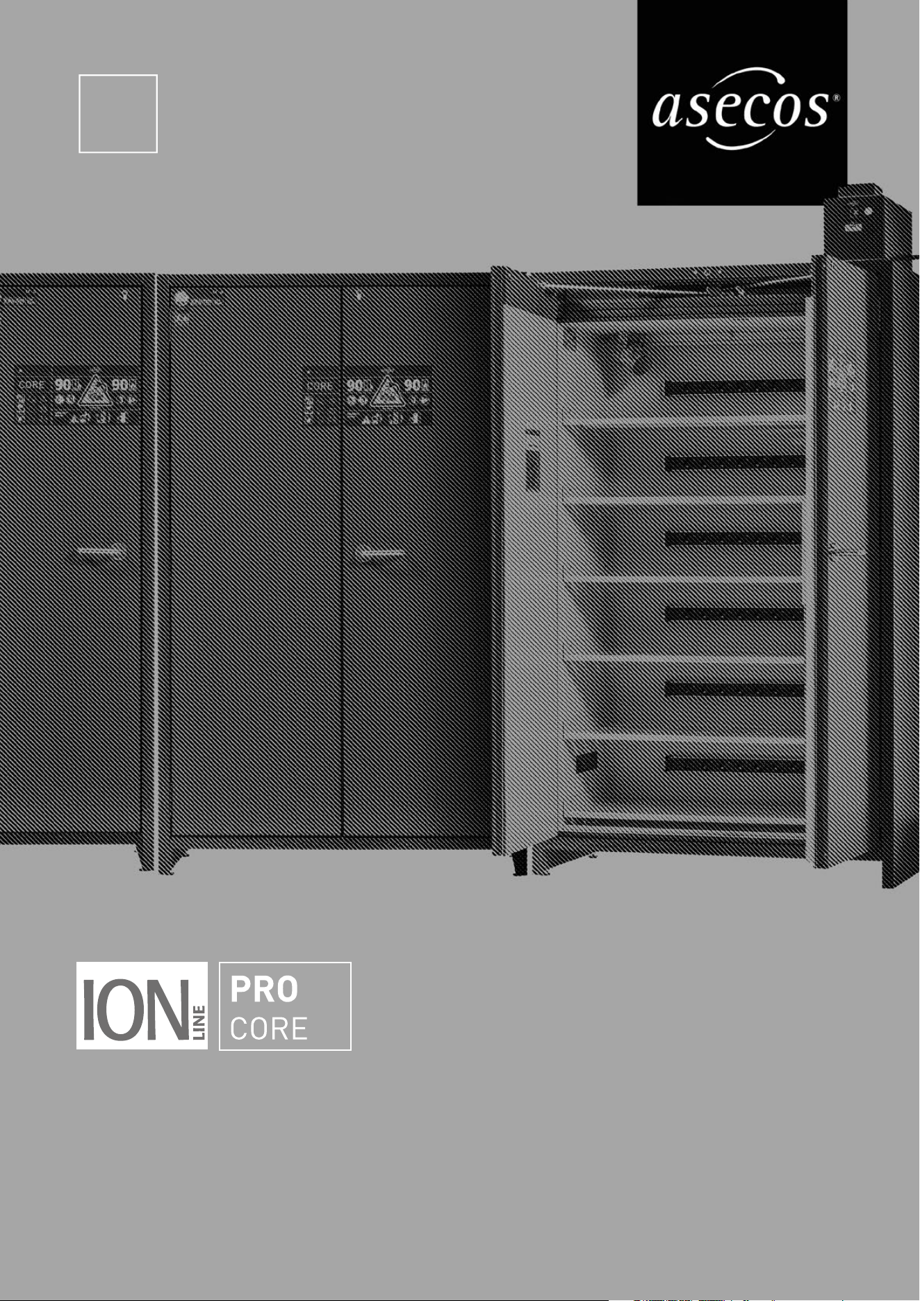
ION-PRO-90 ION-CORE-90
Contact
Company
Street
Name of contact person
email
Serial numbers of safety storage cabinets
Phone No.
Postal code Town
YOUR PERSONAL DOCUMENTATION TO THE asecos
SAFETY CABINET
Dear Customer,
you have made a decisive investment in safety for your company by purchasing this asecos safety
storage cabinet. You now own an innovative product made of top-quality materials guaranteeing
the highest quality standards.
asecos safety storage cabinets have complete authorisation documents. We archive the authori-
sation documents for every individual cabinet, keeping them ready for you should you ever need
them (e.g. for a works inspection or similar). Simply request them using this form.
Tear of or copy that page and return to us by fax with your address and serial number of the
cabinet on it.
Yours sincerely
asecos GmbH
asecos GmbH
Customer service
Weiherfeldsiedlung 16–18
D-63584 Gründau
Fax: +49 60 51 - 92 20-10
email: service asecos.com

4
EN
1. NOTES • GUIDELINES • GUARANTEE ...........................................5
1.1. General safety notes ............................................... 5
1.2. Guarantee ........................................................ 5
1.3. Cabinet Details .................................................... 5
2. TRANSPORT ...............................................................6
2.1. Tilting the cabinet ................................................. 6
2.2. Dismantling of the transport packaging ................................. 6
2.3. In-plant transport .................................................. 7
2.4. Titling onto the side wall ............................................ 7
3. INSTALLATION .............................................................7
3.1. Alignment Of The Cabinets .......................................... 7
4. COMMISSIONING ...........................................................8
4.1. ION-PRO-90: Connection to the power supply .......................... 8
4.2. ION-PRO-90: Self-test .............................................. 9
4.3. ION-PRO-90: Installation of the extraction unit .......................... 9
4.4. ION-PRO-90: Potential-free alarm contact .............................. 9
4.5. ION-CORE-90: Potential-free alarm contact ............................ 10
5. CLOSING .................................................................10
5.1. In general ....................................................... 10
5.2. Locker System ................................................... 10
6. INTERIOR FITTINGS ........................................................10
6.1. Bottom collecting sump ............................................ 10
6.2. Shelves (height-adjustable) ..........................................11
6.3. Total power rating of the power socket strips ............................11
7. STORAGE. . . . . . . . . . . . . . . . . . . . . . . . . . . . . . . . . . . . . . . . . . . . . . . . . . . . . . . . . . . . . . . . .12
7.1. General information on batteries .................................... 12
7.2. Notes on storage and charging ...................................... 12
8. VENTILATION • PRESSURE RELIEF ............................................12
8.1. Extraction unit (IO90.195.120.PC .WDC) ............................... 12
8.2. ION-PRO-90: Smoke detector ....................................... 12
8.3. ION-CORE-90: Smoke detector ...................................... 13
8.4. Pressure relief ................................................... 13
9. ERROR • FALSE ALARMS ....................................................13
9.1. Error during self-test .............................................. 13
9.2. False alarm of the smoke detector ................................... 13
10. ALARM OVERVIEW .........................................................14
10.1. ION-PRO-90: Error and alarm overview ............................... 14
10.2. ION-CORE-90: Error and alarm overview .............................. 14
11. ION-PRO-90: WARNING/FIRE SUPPRESSION SYSTEM ............................14
11.1. Warning message ................................................. 15
11.2. Alarm stage 1 .................................................... 15
11.3. Alarm stage 2 .................................................... 16
12. BATTERY FIRE • EVENT OF FIRE • DISPOSAL ....................................16
12.1. Fire inside the cabinet (battery fire) .................................. 16
12.2. Opening the cabinet after the fire .................................... 17
12.3. Disposal ........................................................ 17
13. SAFET Y CHECKS ...........................................................17
13.1. All Models ....................................................... 17
13.2. ION-PRO-90 ..................................................... 17
13.3. ION-CORE-90 .................................................... 17
13.4. ION-CORE-90: Smoke detector maintenance ........................... 18
13.5. Cleaning ........................................................ 18
13.6. Contact ......................................................... 18
14. TECHNICAL DATA ..........................................................20
15. TECHNICAL DRAWING ......................................................20
15.1. ION-PRO-90 ..................................................... 20
15.2. ION-CORE-90 .................................................... 21
5
EN
1. NOTES • GUIDELINES • GUARANTEE
1.1. GENERAL SAFETY NOTES
• When handling lithium-ion batteries, observe the applicable regulations and the information in these operating
instructions
• Work on the electrical system is to be carried out only with the power turned o and only byqualified electri-
cians – refer here to the regulations of the local electricity supply company.
• General damage to electronic components is to be repaired without delay by an asecos employee.
• Use only intact and undamaged mains cables for the battery charger
• Electrical protection in accordance with local standards must be provided by the customer (cabinets do not
have their own RCD circuit breaker or circuit breaker)
• The on-site installation conditions are to be observed.
• The instructions of the supervisory engineering department must be followed.
• Observe accident prevention regulations and workplace ordinance
• Ensure that the necessary safety checks are only carried out by authorised sta using original
spare parts
• Only use the cabinet after having been properly instructed; access is to be forbidden to unauthorised persons.
• The doors are permanently self-closing and must not be pushed shut manually
• The pivoting area of the doors is to be kept free at all times; doors are to be kept closed
• By assigning trained/authorised technical personnel you can prevent the malfunctions, damage and corrosion
damage that result from inappropriate transport.
• Observe the upper limits for stored quantities, loading etc.
• The following substances may not be stored in the cabinets with a fire suppression system: acids, alkalis,
magnesium, other metals (in powder form)
• Observe the notes on maximum size and general storage of the batteries in these instructions
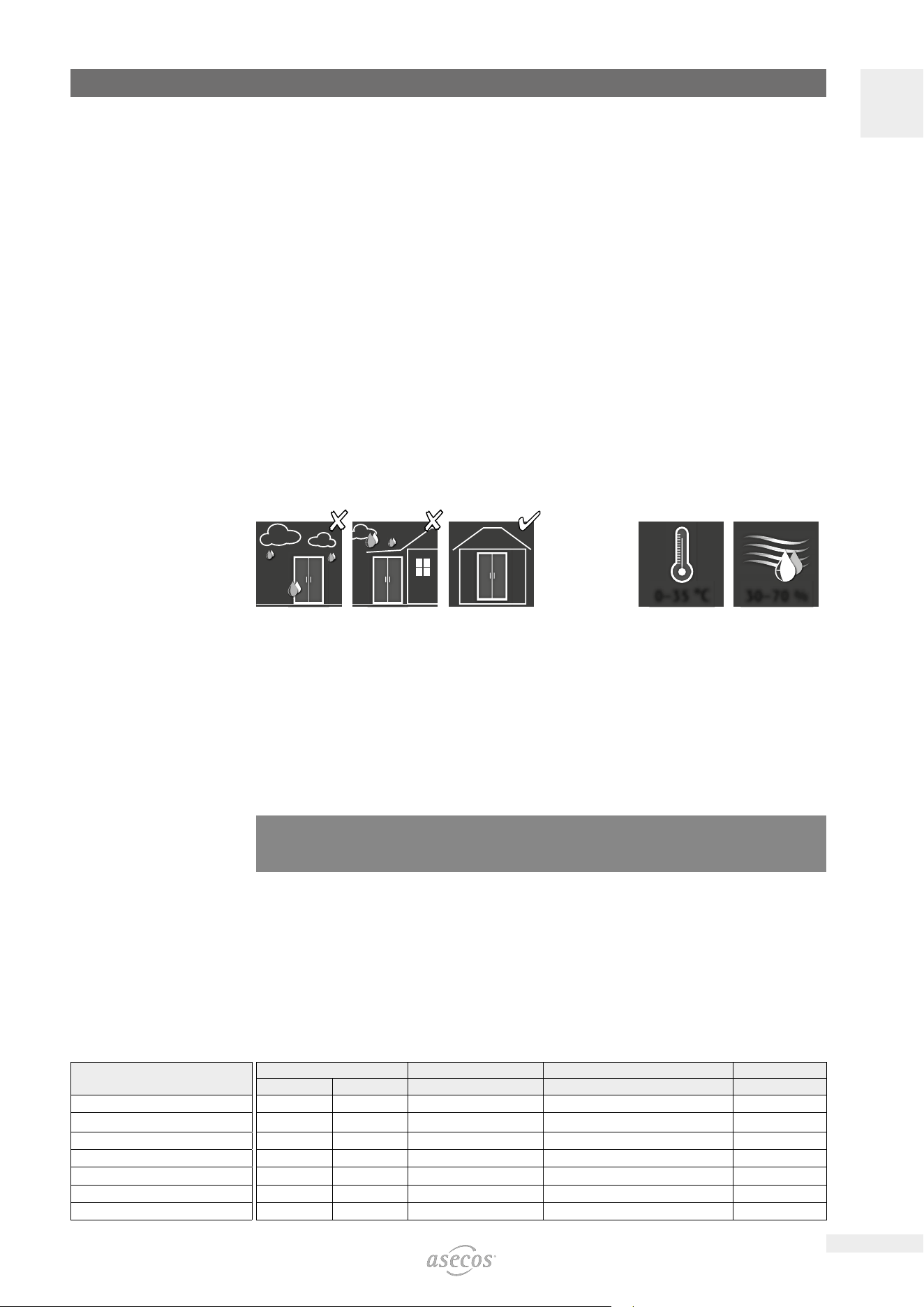
Set-up requirements
0–35 °C 30–70 %
1.2. GUARANTEE
The guarantee for this product is agreed between you (the customer) and your dealer (the seller). As the
manufacturer, asecos guarantees the products listed in the operating instructions for a period of 24 months
from the date of delivery. All model safety equipment are subject to a compulsory annual inspection by spe-
cialised sta authorised by the manufacturer. Otherwise the customer’s guarantee claim against the manufac-
turer expires. Please note that the warranty is also void if holes are drilled or modifications are made without
consulting the manufacturer asecos.
1.3. CABINET DETAILS
Cabinet data: logbook (included with the cabinet)
Technical drawing: see appenidix
Technical data: table in appendix
ION-CORE-90
Safety storage cabinets for lithium-ion batteries
Comprehensive fire protection with the proven evacuation and alarm forwarding concept. During active stor-
age, lithium-ion batteries or battery packs are charged or partially discharged (60-70%) in the cabinet using a
charger.
ION-PRO-90
Safety storage cabinets for lithium-ion batteries
Extended protection for professional handling of lithium-ion batteries including 3-stage alarm and active fire
suppression system. During active storage, lithium-ion batteries or battery packs are charged or partially dis-
charged (60-70%) in the cabinet using a charger.
Model
Lithium ion batteries
Storing Charging Integrated ventilation Fire supression unit Alarm system
ION-CORE-90
IO90.195.060.CC.WDC
4 4 4
IO90.195.120.CS.WDC
4 4
IO90.195.060.CS.WDC
4 4
ION-PRO-90
IO90.195.120.PC.WDC
4 4 4 4 4
IO90.195.120.PS.WDC
4 4 4
6
EN
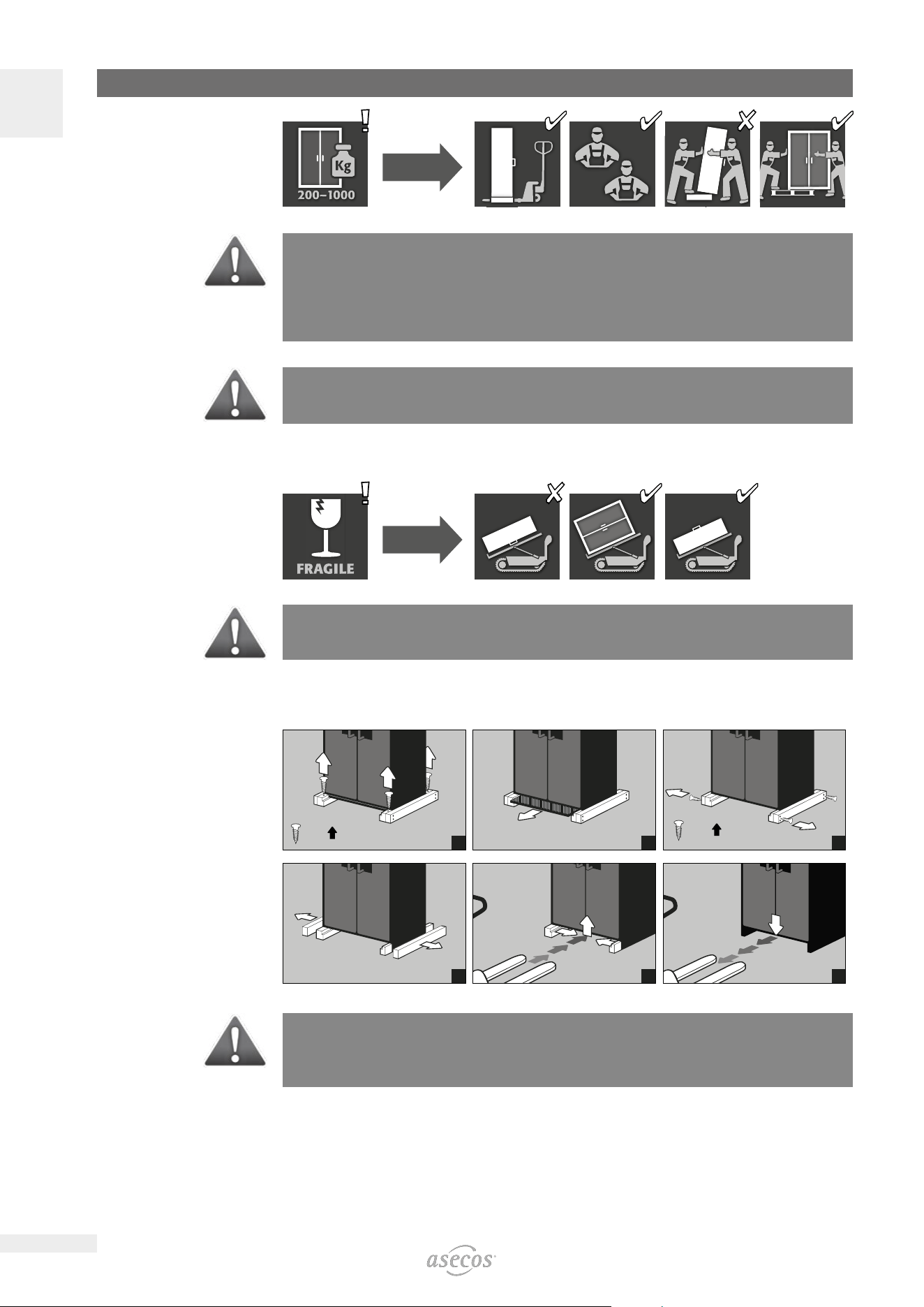
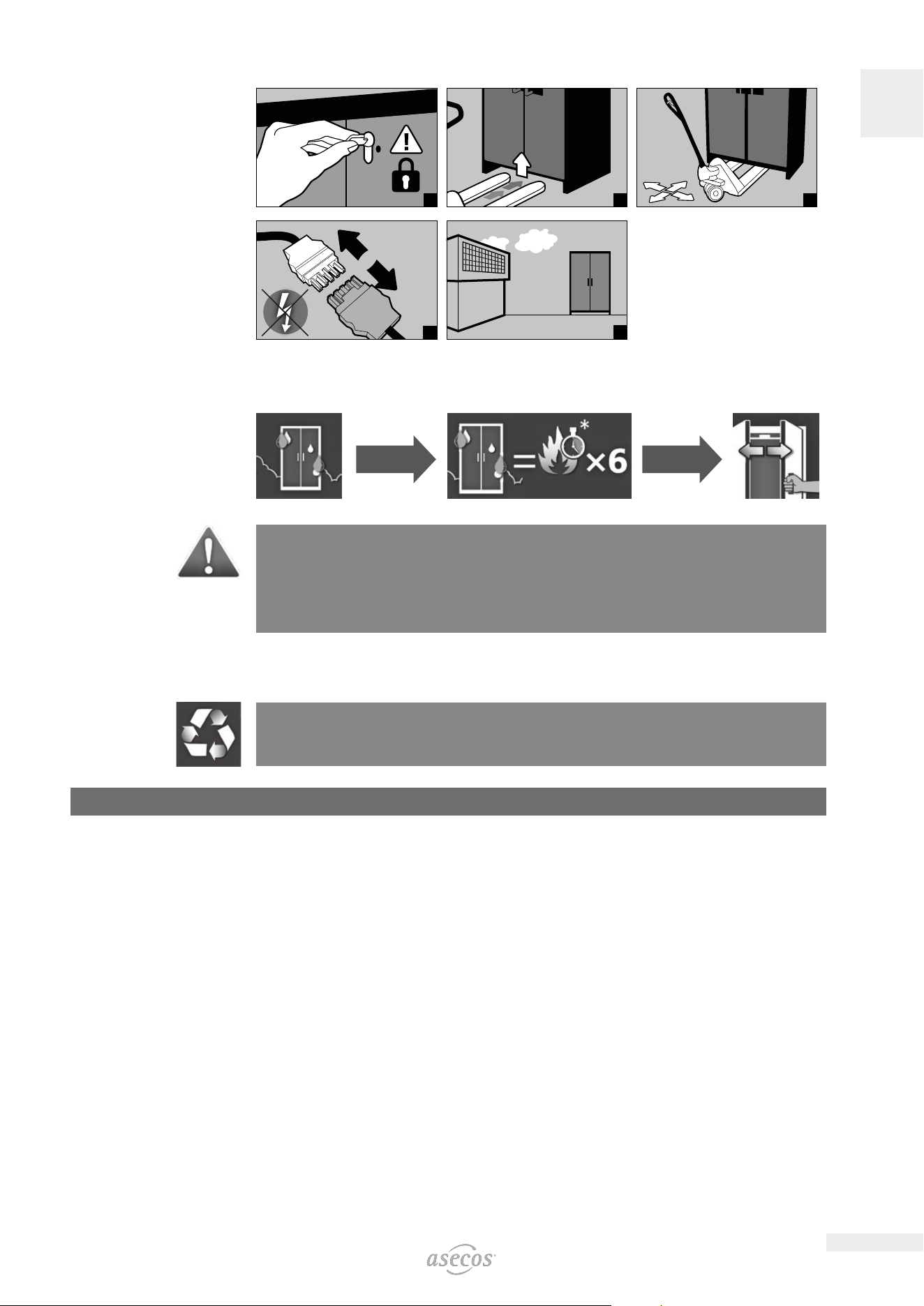
2. TRANSPORT
CAUTION:
Transport the cabinet in an upright position on a pallet truck, tied and secured against slipping, until the
final place of installation is reached.The transport locks in the door joints may only be removed directly
at the place of installation! Inappropriate transport can lead to concealed damage to the fire protection
insulation!We can only guarantee the necessary quality if the cabinet is transported to the place of its use
by our specially trained sta.
ATTENTION with cabinets including extraction unit:
The doors must be locked prior to transport! The extraction unit is inside the cabinet and is only mounted
after the in-plant transport to the place of use.
2.1. TILTING THE CABINET
CAUTION:
Tilting the cabinet may only be done without jolts!
2.2. DISMANTLING OF THE TRANSPORT PACKAGING
1
= 4×
2
= 8×
3
4
5
6
CAUTION:
Cabinets with a width of 600 mm: The clear entry width of the base is 520 mm.
Please note this when choosing your pallet truck!Devices with widths greater than the entry widths must
not be used.
7
EN
2.3. IN-PLANT TRANSPORT
• In-plant transport is also possible without transport locks (inserted as standard in the door joints)
ATTENTION with cabinets including extraction unit:
The doors must be locked prior to transport! The extraction unit is inside the cabinet and is only mounted
after the in-plant transport to the place of use.
1 2
= 4×
3
2.4. TITLING ONTO THE SIDE WALL
• Titling onto the side wall is only possible with the optionally available tilting bracket (order no. 29556).
1 2 3
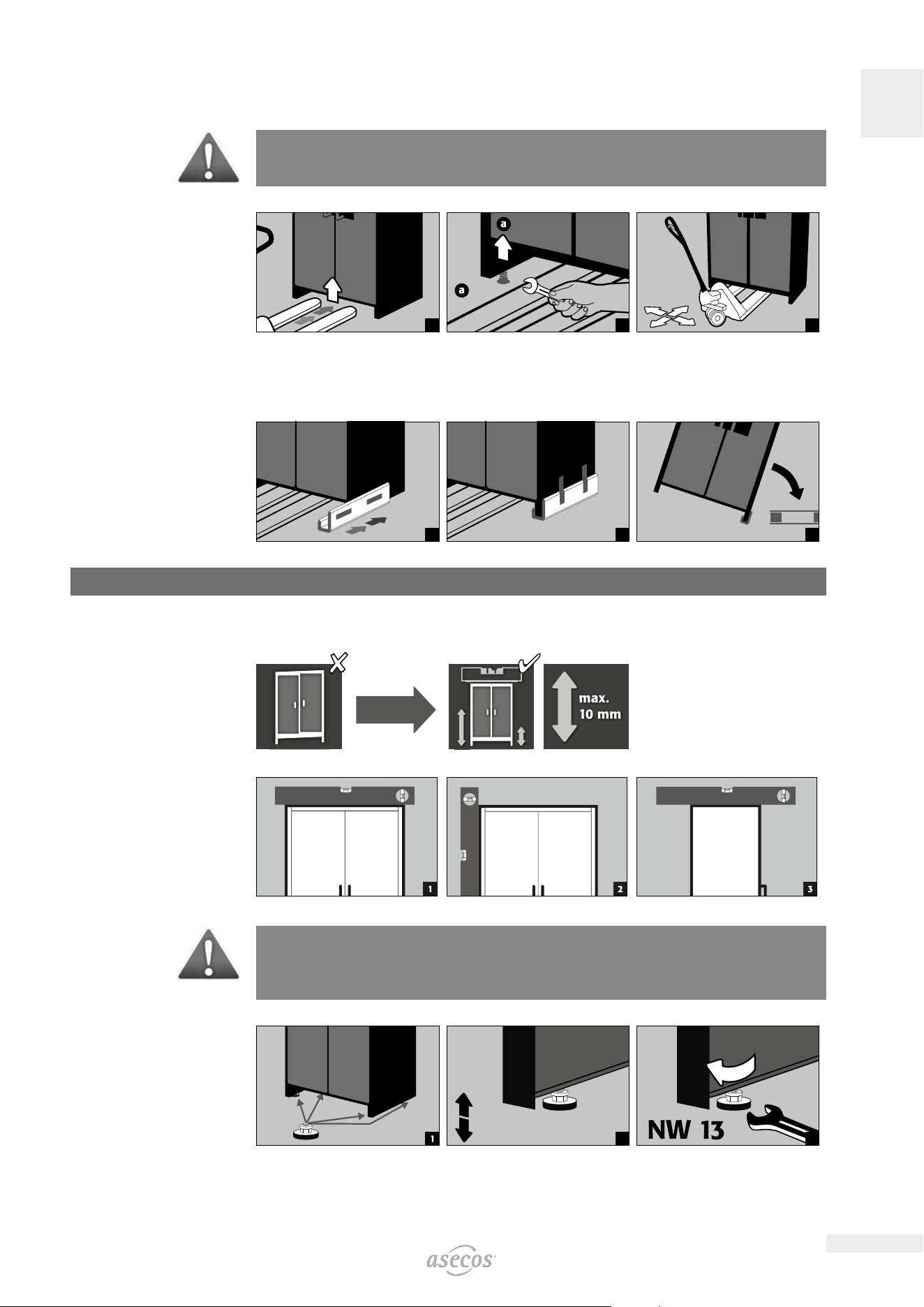
3. INSTALLATION
3.1. ALIGNMENT OF THE CABINETS
CAUTION:
Door elements must not scrape against the fire prevention seals in the fold of the door when opening and
closing! Doors with an automatic closing mechanism must close automatically from every position and the
lock must be able to lock!
4×
2
max. 2× (!)
3
8
EN
4. COMMISSIONING
• Before putting into operation for the first time, the user must carry out an examination of the safety storage
cabinet for possible damage, such as defective or loose sealing elements, correct alignment and perfect func-
tioning of the door elements.
Use the cabinet and accessories only if they are in an orderly condition.
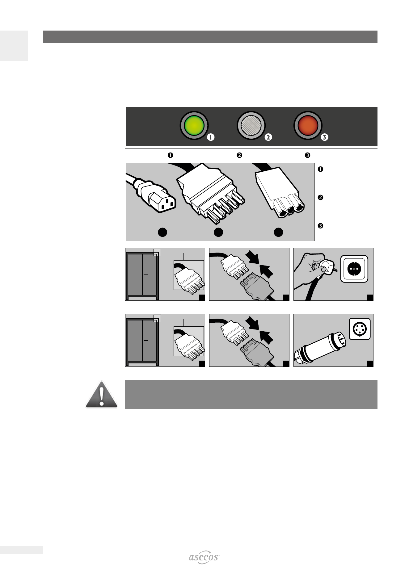
4.1. ION-PRO-90: CONNECTION TO THE POWER SUPPLY
Connections on the headpiece:
LED: Operating (green) RESET BUTTON LED: Error (red)
1 2 3
Mains connection for
extraction unit
(IO90.195.120.PC.WDC)
Mains plug connector
Potential-free switch
contact
Connection to the power
supply
1
2
230 V
3
Connection to the power
supply with 400 V (optional
with item 38038)
1
2
400 V
3
NOTE:
Retrofitting is easy due to the plug-in connection, so that no intervention in the electrical components is
necessary. The power supply must be fused on site with a maximum of 16A
9
EN
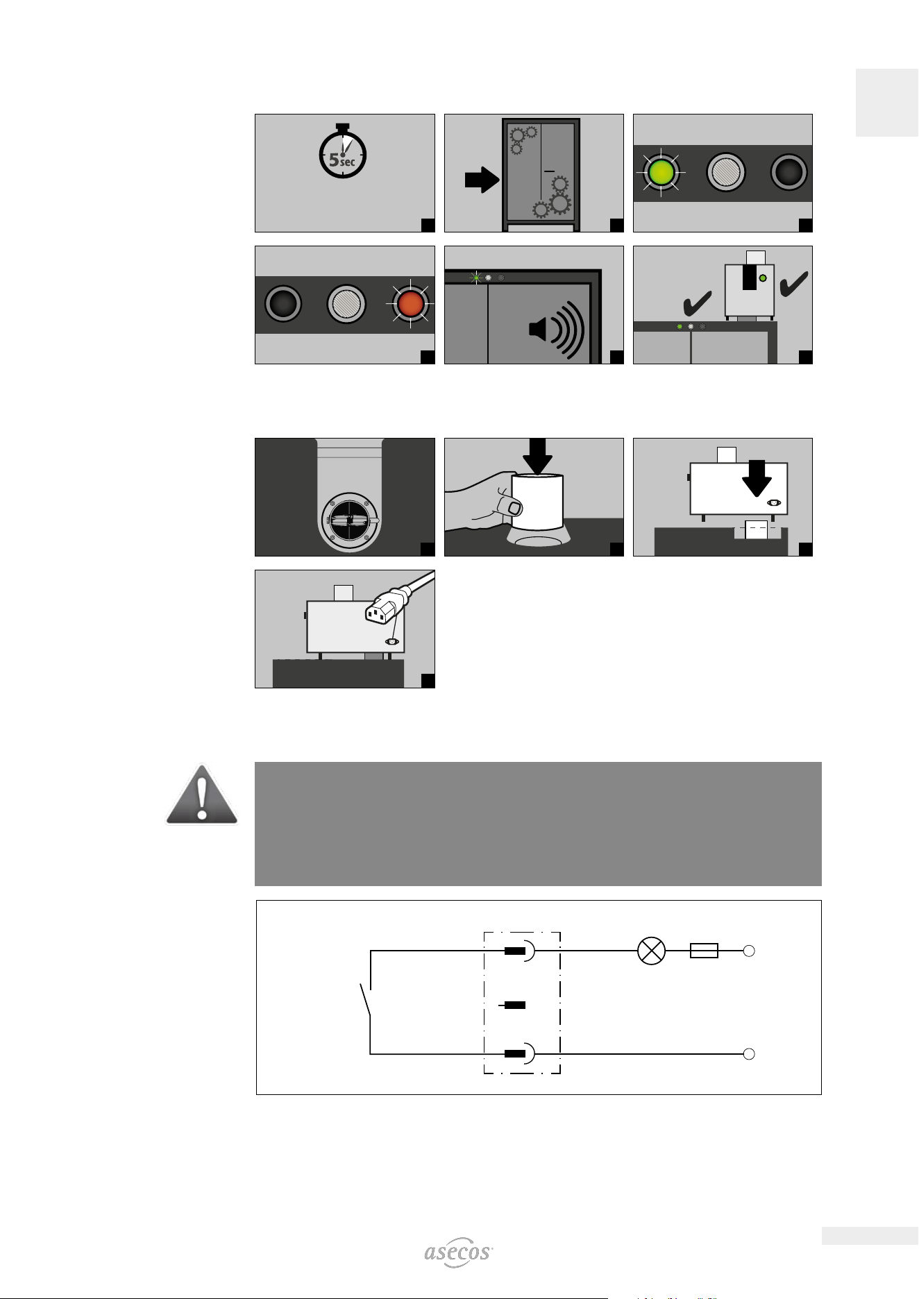
4.2. ION-PRO-90: SELF-TEST
Starts 5 seconds after
connection to the
mains supply
1
2
3
4
5
6b
4.3. ION-PRO-90: INSTALLATION OF THE EXTRACTION UNIT
1
2
3
4
4.4. ION-PRO-90: POTENTIAL-FREE ALARM CONTACT
NOTE:
The potential-free alarm contact is used to connect a signal to a control centre/control room. Direct
integration into a fire alarm control panel (FACP) is not recommended or may only be carried out in consul-
tation with the person responsible for the system.
However, it is always recommended to connect the signal to a manned control centre/control
room!
The potential-free switching contact must always be connected by the customer (not a service).
(AC) / (DC)
(AC) / (DC)
Connector
Internal
alarm contact
Connection instructions
• Use only the supplied mating part (colour-coded black) to the plug for the connection
• The connection must be done by a qualified electrician
• The contact is designed for a max. DC voltage of 30 V or a max. AC voltage of 230 V
• The maximum current load is 10 A
• The switch contact is normally closed!
• The switch contact opens as soon as mains voltage is present and no error is pending (device is „ready to
operate“)
10
EN
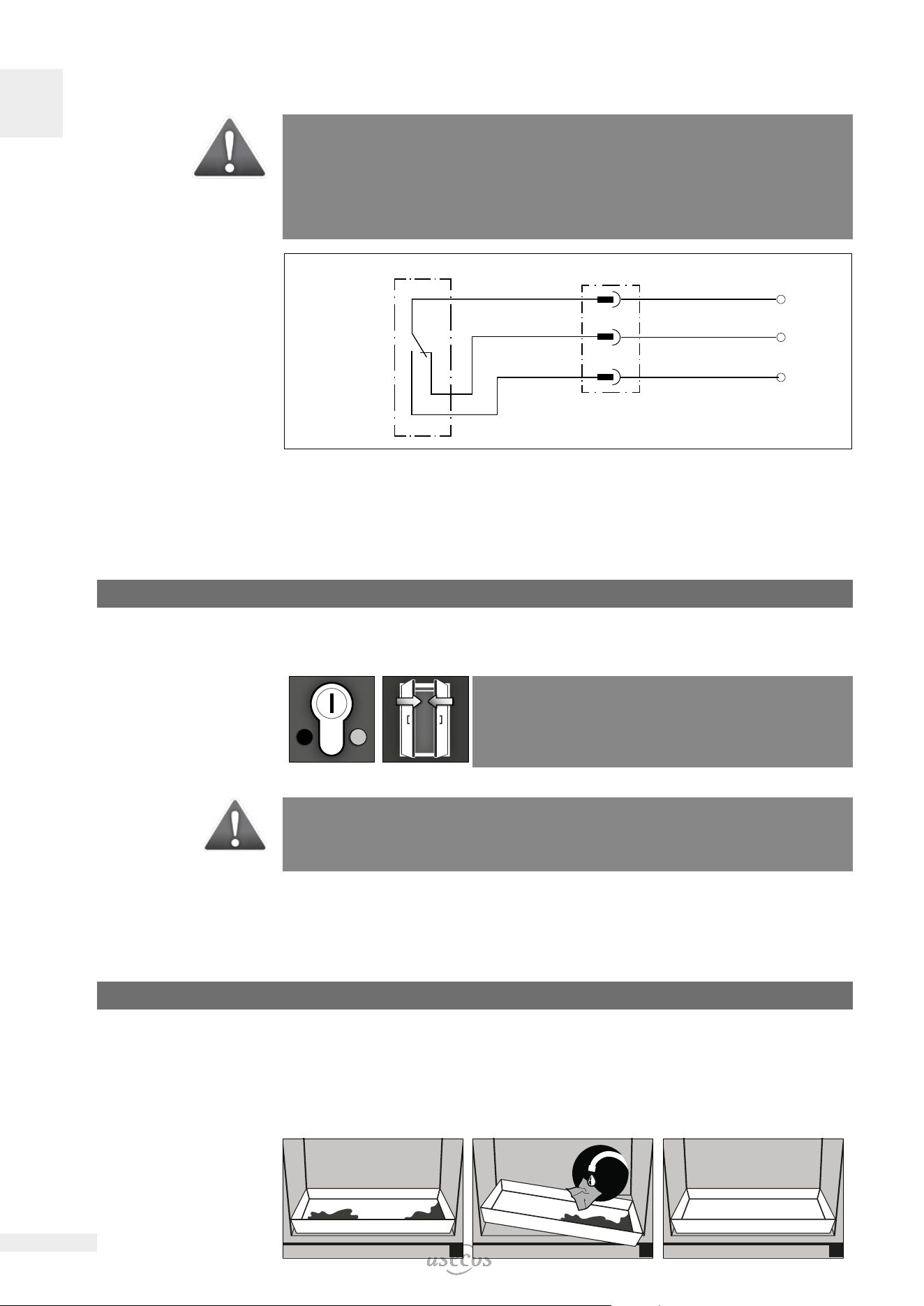
4.5. ION-CORE-90: POTENTIAL-FREE ALARM CONTACT
NOTE:
The potential-free alarm contact is used to connect a signal to a control centre/control room. Direct
integration into a fire alarm control panel (FACP) is not recommended or may only be carried out in consul-
tation with the person responsible for the system.
However, it is always recommended to connect the signal to a manned control centre/control
room!
The potential-free switching contact must always be connected by the customer (not a service).
11
1
(AC) / (DC)
(AC) / (DC)
(AC) / (DC)
2
L
1214
Connector
Internal
alarm contact
Connection instructions
• Use only the supplied mating part (colour-coded brown) to the plug for the connection.
• The connection must be done by a qualified electrician.
• The internal switch contact is designed for a max. DC voltage of 24 V or a max. AC voltage of 230 V.
• The maximum current load is 5 A at 230 V AC and 10 A at 24 V DC.
• The internal switch contact is a changeover contact; in case of alarm, therefore, the switching state may be
queried as „opened“ or „closed“.
5. CLOSING
5.1. IN GENERAL
The doors are permanently self-closing and self-locking. They
must not be closed manually. The cabinets have a profile cylinder
lock with locking status indicator and can be integrated into a locking
system. A profile half cylinder (30/10) with adjustable cam must be
used.
ATTENTION:
The owner/user must ensure that all doors are kept closed whenever the contents of the cabinet are
not being accessed. In general, it must be noted that the cabinets do not possess an emergency unlocking
facility. This means that persons trapped inside the cabinet cannot free themselves!
5.2. LOCKER SYSTEM
• Lockers can be closed manually and each has a cylinder lock with its own key pair
• An additional master key opens all 7 lockers
• Lockers and keys can be individually numbered using the key ring set and sticker sheet provided
6. INTERIOR FITTINGS
6.1. BOTTOM COLLECTING SUMP
Leaks:
• Liquid in the sump is to be collected using suitable means.
• The choice of means is your own responsibility.
1
2 3
11
EN
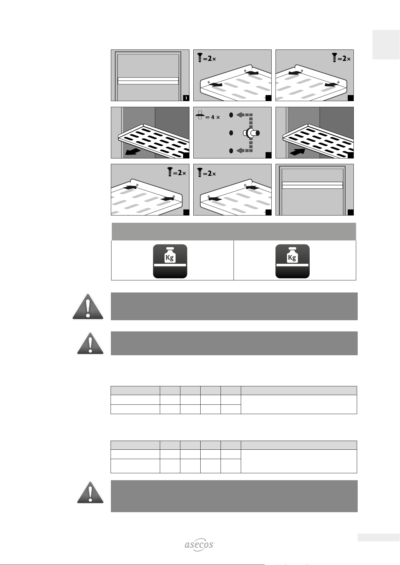
6.2. SHELVES (HEIGHT-ADJUSTABLE)
2
3
4
5 6
7
8
9
LOAD CAPACITY (KG/
DRUM PLATFORM)
IO90.195.120.PC.WDC
IO90.195.120.PS.WDC
IO90.195.120.CS.WDC
IO90.195.060.CC.WDC
IO90.195.060.CS.WDC
max. 75 kg max. 25 kg
CAUTION:
Please note that dynamic forces act when loading the cabinets. Always place batteries carefully in the
cabinet!
CAUTION:
The position of the shelves / 2nd level drawer and socket strips cannot be changed.
6.3. TOTAL POWER RATING OF THE POWER SOCKET STRIPS
Standard: single-phase, 230 V
Version EU CH UK FR other regions:
fusing 16 A 10 A 13 A 16 A Please get in touch with your asecos contact person. The
maximum power and protection may dier here.
max. total power 3,68 kW 2,3 kW 2,99 kW 3,68 kW
Optional: 3-phase, 400 V (accessories article 38038)
Note on model with a width of 600 mm IO90.195.060.CC.WDC: Only 2 of the 3 connected phases are
required by the cabinet electronics. The third phase remains unused.
Version EU CH UK FR other regions:
fusing 3 x 16 A 3 x 10 A 3 x 13 A 3 x 16 A Please get in touch with your asecos contact person. The
maximum power and protection may dier here.
max. total power 11,04
kW
6,9 kW 8,97 kW 11,04
kW
ATTENTION:
The load on the system is to be distributed as evenly as possible over the power socket strips! The
individual power strip must not be loaded with more than the specified power max. (see table)!
The necessary fuse protection is to be provided by the customer!
12
EN
7. STORAGE
7.1. GENERAL INFORMATION ON BATTERIES
ATTENTION:
Never store obviously damaged lithium-ion batteries inside buildings.
Dispose of them without delay in disposal containers that are provided outside the building and approved
for transport.
CAUTION
Only batteries with a maximum output of 2 kW and a maximum weight of 15 kg may be stored in the
cabinets.
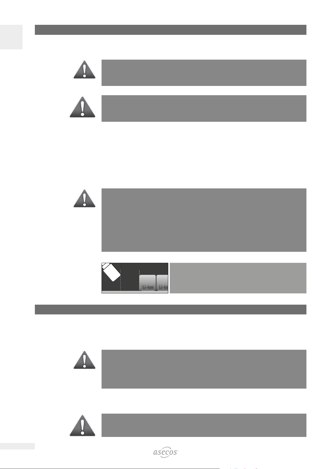
7.2. NOTES ON STORAGE AND CHARGING
Storage
• It is recommended to store new and used lithium-ion batteries separately (each on a dierent storage level)
in the safety storage cabinet.
Occupation of the storage levels (IO90.195.XXX.XX.WDC)
Grid shelves may be covered only up to 60% by battery chargers and batteries in order to ensure trouble-free
operation of the fire suppression system and sucient air circulation.
CAUTION:
Full-surface occupancy of the storage levels is not permitted.
ION-PRO-90:
The following substances must not be stored in the cabinets with fire suppression system:
Acids, bases, magnesium, other metals (in powder form).
Heat is generated during the charging of a lithium-ion battery!
Please note: The technical ventilation (to avoid heat accumulation in the interior) needs to be kept in
operation permanently.
Li-Ion Li-Io
n
150 mm
CAUTION:
A distance of min. 150 mm must be maintained in the area in
front of the fire suppression unit.
8. VENTILATION • PRESSURE RELIEF
8.1. EXTRACTION UNIT (IO90.195.120.PC.WDC)
• See point 4.4 for the installation.
The green indicator lamp signals that the fan is switched on.
ATTENTION:
Heat is generated during the charging of a lithium-ion battery!
Please note:
The technical ventilation (for the avoidance of heat accumulation in the interior) must run continuously
Repairs to the extraction unit are only to be carried out by specialists specifically trained for this. Given
damage the appliance is to be repaired or replaced by the manufacturer.
8.2. ION-PRO-90: SMOKE DETECTOR
ATTENION:
The complete warning/fire suppression system is active only with mains operation. The integrated smoke
detector is part of the entire fire suppression system (direct power supply).
13
EN
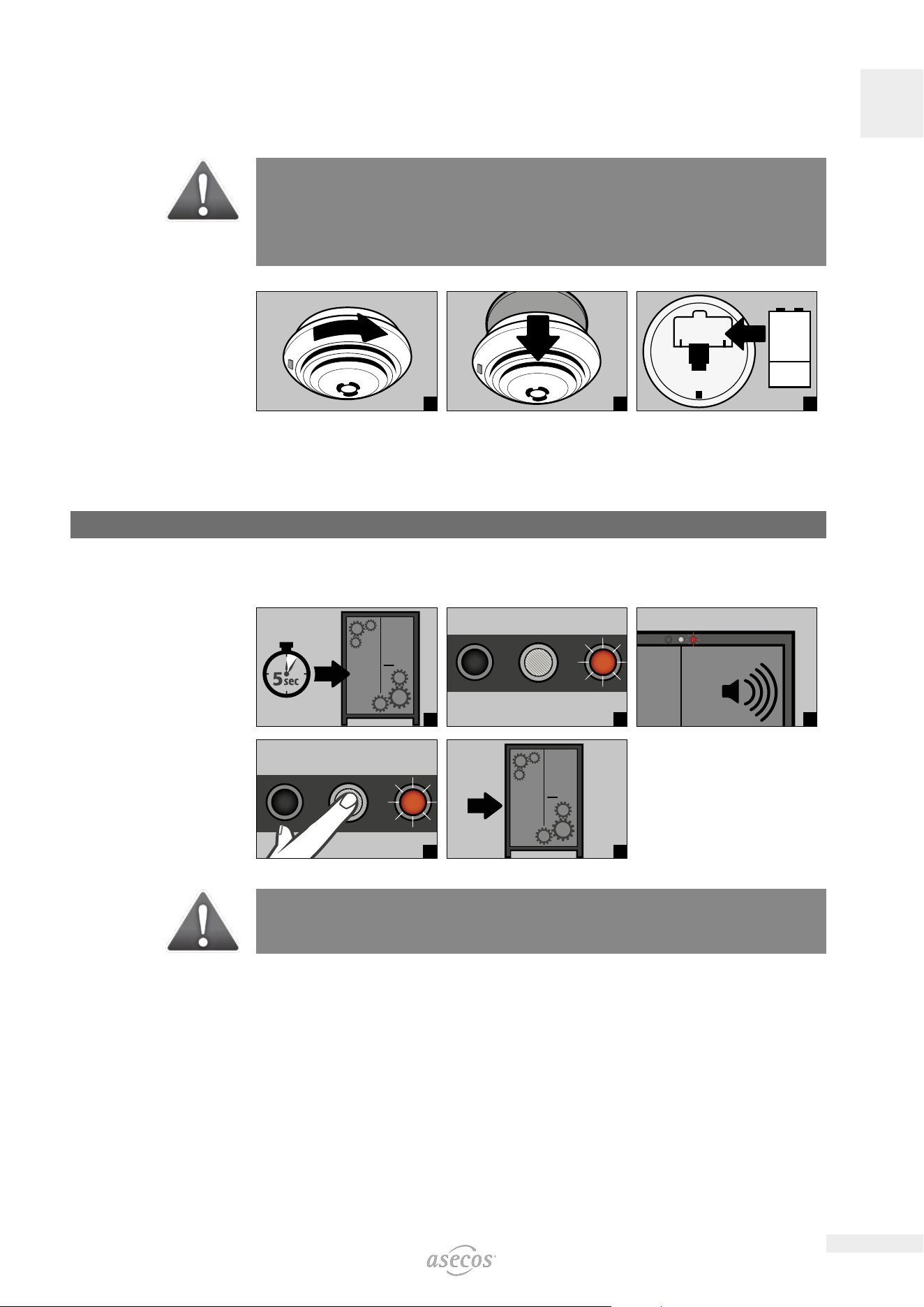
8.3. ION-CORE-90: SMOKE DETECTOR
These models have a battery-operated smoke detector.
Battery change
CAUTION:
The use of rechargeable batteries is not permitted!
The life of the battery is highly dependent on local conditions such as temperature, temperature fluctua-
tions, humidity and the number of test alarms/alarms, among other things. In the case of lithium, this is up
to 5 years. The smoke detector announces a necessary battery change approx. 30 days in advance (see
10.2).
1
2
9V
3
8.4. PRESSURE RELIEF
All ION-LINE models have a pressure relief flap built into the head section, which opens briefly in the event of
a pressure increase and thus releases the pressure from the cabinet.
9. ERROR • FALSE ALARMS
9.1. ERROR DURING SELF-TEST
1
2
5
3
5
sec
4
5
ATTENTION:
After pressing the reset button, the self-test begins again. If the error persists, please contact the asecos
Service department.
9.2. FALSE ALARM OF THE SMOKE DETECTOR
• By interrupting the power supply for a few seconds, the smoke detector is reset and the system returns to
normal operation.
14
EN
10. ALARM OVERVIEW
10.1. ION-PRO-90: ERROR AND ALARM OVERVIEW
EVENT LED GREEN LED RED ACOUSTIC ALARM ACTIONS
Error during self-test o turned on 5 signal tones 1.) Restart with RESET
button if error persists: 2.)
Contact Service
Service interval reached flashing o o Contact Service
Power failure o Flashes every 20 seconds 3 short signal tones every
60 seconds
Check power supply
Warning message:
Temperature in the
cabinet >50 °C
o turned on Tone interval
(every 2 seconds for 250
ms)
see 11.1
Alarm stage 1:
Smoke detector detects
smoke in the cabinet
o turned on medium tone interval
(every 0.5 seconds for
250 ms)
see 11.2
Alarm stage 2:
Smoke detector detects
smoke in the cabinet,
Temperature in the
cabinet >70 °C
o flashing fast tone interval
(every 0.25 seconds for
125 ms)
see 11.3
10.2. ION-CORE-90: ERROR AND ALARM OVERVIEW
EVENT
LED RED ON SMOKE
DETECTOR ACOUSTIC ALARM ACTIONS
Smoke detector detects
smoke in the cabinet
flashing pulsating alarm tone see 12.1
Triggered by connected
detectors
o pulsating alarm tone The triggering detector can be
identified by parallel to the alarm
tone flashing LED
Battery replacement due flashing short beep every 45 seconds see 8.3
Operational readiness flashes every 45 seconds o
Malfunction flashes alternately with the
beep
short beep every 45 seconds change smoke detector
11. ION-PRO-90: WARNING/FIRE SUPPRESSION SYSTEM
• The warning/fire suppression system oers the option of connection to a constantly manned building man-
agement system or fire alarm centre.
• Make use of this option so that trained rescue personnel can be quickly alerted and be on-site in a very short
time and, following an initial assessment of the situation, immediately initiate further measures (for example,
transporting the cabinet out of the building).
• In this way consequential damage to the building and personal injuries can be avoided.
• The extinguishing agent, based on potassium carbonate, is harmless in the necessary extinguishing agent
concentration and has no harmful eects on the human organism.
• In case of triggering, the aerosol is ejected at a high temperature and temperatures of over 300 °C are briefly
generated in front of and on the housing of the fire suppression cartridge (according to the manufacturer‘s
data, a minimum distance to combustible materials need not be maintained; however, a distance of at least
150 mm to the fire suppression cartridge should generally be maintained).
• After triggering of the fire suppression cartridge, ventilate the room and the cabinet well, observing the instruc-
tions in point 12.
ATTENION:
The complete warning/fire suppression system is active only with mains operation. The integrated smoke
detector is part of the entire fire suppression system (direct power supply).
15
EN
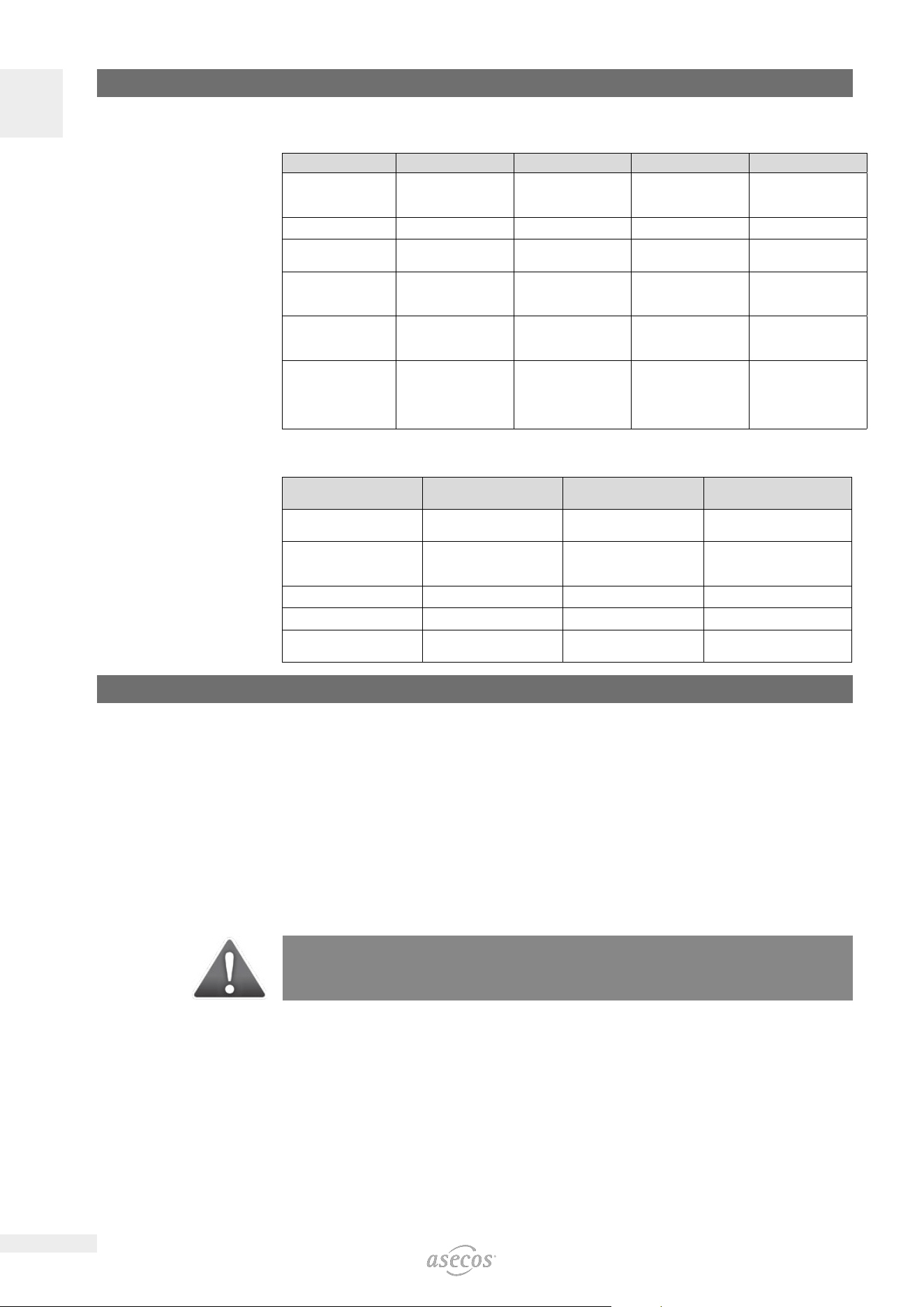
11.1. WARNING MESSAGE
>50 °C
1
2
3
if connected
4 5
• Actions
Immediate visual inspection of the system by the company’s own qualified personnel.
Initiation of necessary actions.
If the interior temperature falls below 50 °C, the system returns to normal operation and the visual and acous-
tic signals are switched o.
11.2. ALARM STAGE 1
!
1
2
3
if connected
4
5
IO90.195.120.PC.WDC
6
• Actions
Immediate visual inspection of the system by technical personnel (e.g. fire brigade).
Subsequently, initiation of necessary actions.
If the smoke detector does not detect any further smoke development in the cabinet, the system can be reset
to normal operation by briefly disconnecting the mains voltage.
16
EN
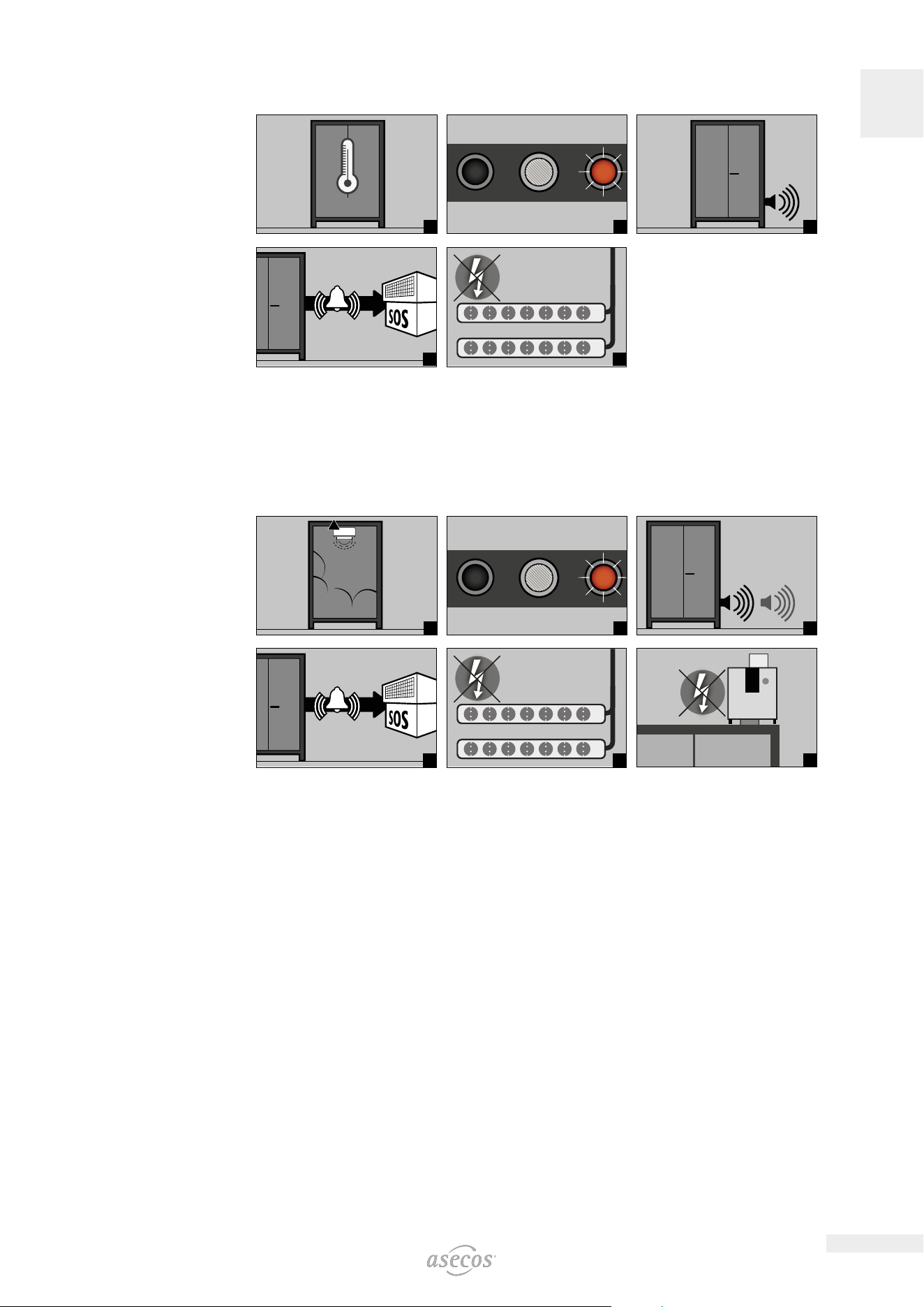
11. 3. ALARM STAGE 2
>70 °C
1
2
3
if connected
4
5
6
IO90.195.120.PC.WDC
7
• Actions
Immediate visual inspection of the system by technical personnel (e.g. fire brigade).
Subsequently, initiation of necessary actions.
See 12.1 for the transport of the cabinets out of the building.
NOTE:
After the fire suppression device has been triggered, the safety cabinet must be subjected to a thorough
inspection so that both fire protection and CE conformity are maintained. For this purpose, the cabinet
must be handed over to the main factory of asecos GmbH in Gründau, where the specialist department -
depending on the degree of damage - will make an assessment of the economic eciency and technical
possibilities of a repair. The customer then receives an oer of either a repair or a replacement, which can
be handed over to the responsible property insurer.
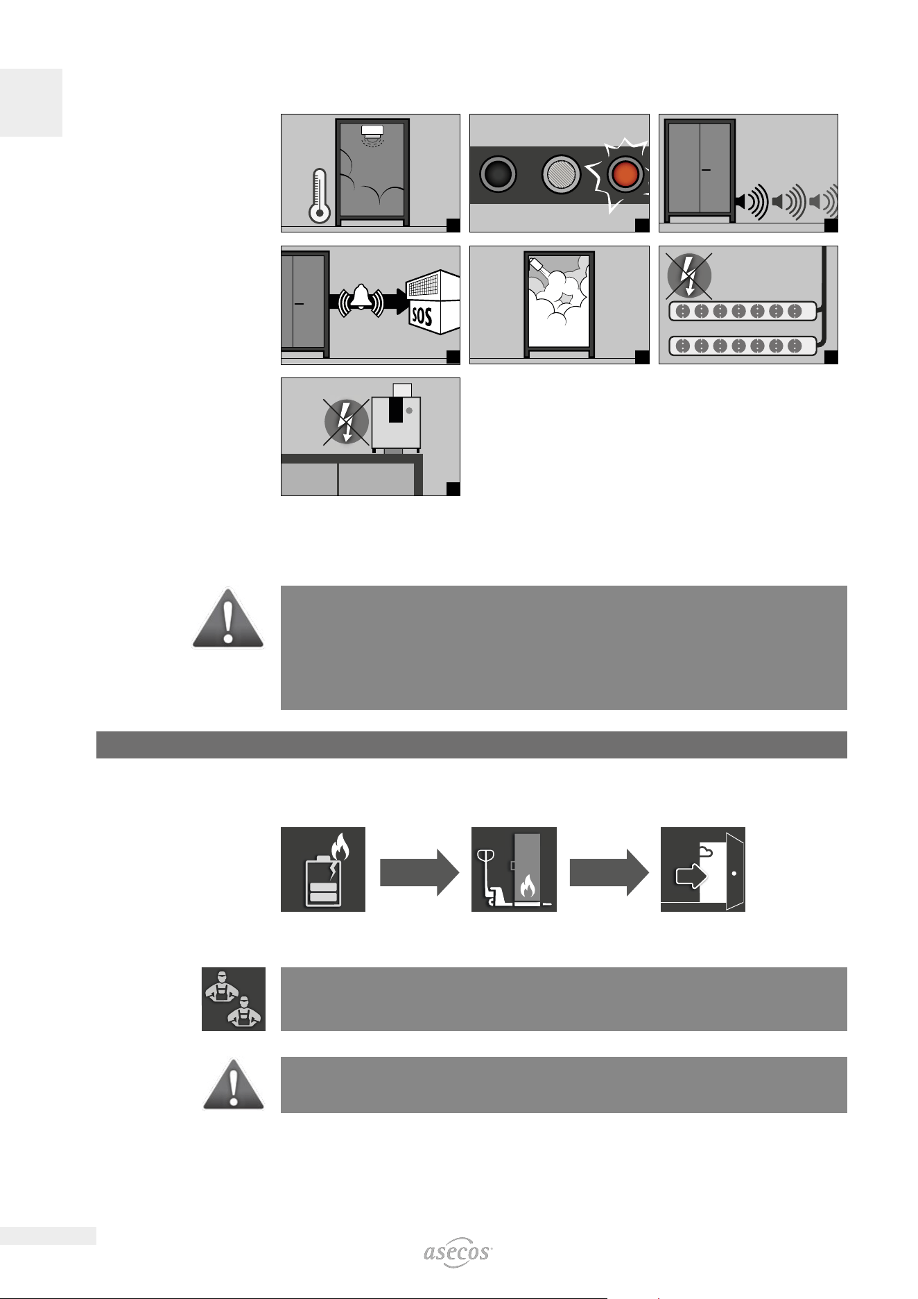
12. BATTERY FIRE • EVENT OF FIRE • DISPOSAL
12.1. FIRE INSIDE THE CABINET (BATTERY FIRE)
• For fast transport the cabinets are equipped with a transport base.
The cabinets are automatically disconnected from the mains supply in the case of transport.
NOTE for 2-door tall cabinets
Evacuation by at least 2 persons is recommended. Only qualified personnel (e.g. fire department) may carry
out transportation in the event of a fire.
CAUTION:
The doors must be locked before transport! Depending on the door heights, it may be necessary to remove
the ventilation attachment beforehand. Transport may only be carried out by qualified personnel!
17
EN
1
2
3
4
5
12.2. OPENING THE CABINET AFTER THE FIRE
CAUTION:
Do not open the cabinet until it has cooled down. This is 6 times the fire duration!
The cabinet may only be opened by authorised personnel (e.g. fire brigade)!
Depending on the duration of the fire, an ignitable vapour-air mixture may have formed, therefore remove
all ignition sources within a 10-metre radius around the cabinets before opening.
Use only non-sparking tools! Open the cabinets with extreme caution!
12.3. DISPOSAL
The models can be disposed of once they have been dismantled and the materials sorted.
13. SAFETY CHECKS
13.1. ALL MODELS
As safety equipment the cabinets have to be checked for safety at least once per year. The next checking date
can be taken from the service sticker on the outside of the door. This annual check can be carried out with the
necessary care, and for securing your warranty claims in the case of fire, only by an authorised asecos employ-
ee (refer also to our service brochure regarding this).
13.2. ION-PRO-90
A necessary service is automatically indicated by the cabinet by a flashing green LED.
Within the context of the annual check, the fire suppression system, smoke detector and sensors will be
checked in addition to the check of all safety-related parts.
13.3. ION-CORE-90
A necessary service is indicated by service sticker on the door of the cabinet.
Within the context of the annual check, all safety-related parts, the smoke detector and the alarm signalling will
be checked.
18
EN
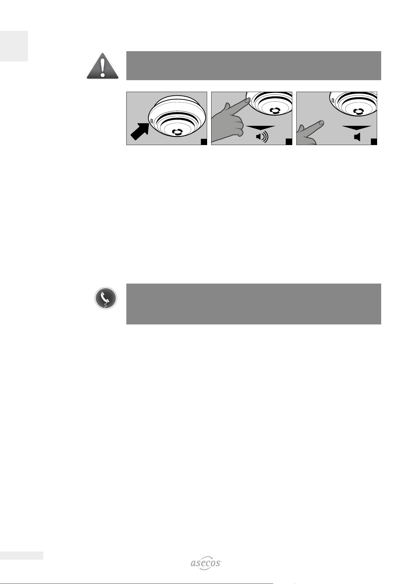
13.4. ION-CORE-90: SMOKE DETECTOR MAINTENANCE
ATTENTION
In accordance with DIN 14676 the proper function of the smoke detector must be checked at least once
per year.
1
> 20 sec
2
< 5 sec
3
• The smoke detector is completely tested with the LED test button (fig. 1): battery function test, electronic
smoke chamber test and a test of the evaluation electronics.
• After releasing, the test alarm resets itself
• Following a successful test, the alarm is silenced and the LED flashes every 45 seconds - the smoke detector
is ready to operate
• If the test failed, see error and alarm overview for error analysis
Self-test
• The smoke detector carries out an automatic self-test, in which the evaluation electronics as well as the volt-
age and the internal resistance of the battery are checked about every 45 seconds.
• This check is signalled by a short flashing signal of the red LED.
13.5. CLEANING
The cabinets can be cleaned with a mild household cleaner and a soft cloth.
In case of damage please contact your dealer in order to have the cabinet repaired using original spare parts.
13.6. CONTACT
CONTACT:
In the case of defects or complaints about our products (within and also after the warranty period), and for
requesting safety checks or taking out a service contract, please contact our service hotline on:
Tel: +44 1785 22 70-90 | info@asecos.co.uk (for great Britain and Ireland)
Tel: +49 1805 92 20 92 | service@asecos.com (international)

19
EN
20
EN
14. TECHNICAL DATA
ION-PRO-90 IO90.195.120.PC.WDC IO90.195.120.PS.WDC
Type 90 90
External dimensions W x D x H 1193 x 615 x 2224 mm 1193 x 615 x 1953 mm
Internal dimensions W x D x H 1050 x 522 x 1647 mm 1050 x 522 x 1647 mm
Weight without interior equipment kg 424 424
Distributed load kg/m² 531.00 531.00
Extraction air DN 75 75
Entry width transport base mm 1120 1120
Entry height transport base mm 90 90
Max. shelf load (evenly distributed) kg 75 75
Power consumption of control electronics
Power consumption in operation W 47,5 1,5
Nominal voltage V 230/400 230
Frequency Hz 50/60 50/60
Total power rating of the power socket strips
EU CH UK FR/BE
Fuse (1-phase) A 16 10 13 16
Power max. (1-phase) kW 3,68 2,3 2,99 3,68
Fuse (3-phase) A 3 x 16 3 x 10 3 x 13 3 x 16
Power max. (3-phase) kW 11,04 6,9 8,97 11,04
ION-CORE-90 IO90.195.060.CC.WDC IO90.195.060.CS.WDC IO90.195.120.CS.WDC
Type 90 90 90
External dimensions W x D x H 599 x 615 x 1953 mm 599 x 615 x 1953 mm 1193 x 615 x 1953 mm
Internal dimensions W x D x H 450 x 522 x 1647 mm 450 x 522 x 1647 mm 1050 x 522 x 1647 mm
Weight without interior equipment kg 265 265 424
Distributed load kg/m² 894.00 894.00 531.00
Extraction air DN 75 75 75
Entry width transport base mm 526 526 1120
Entry height transport base mm 90 90 90
Max. shelf load (evenly distributed) kg 25 75
Power consumption of control electronics
Power consumption in operation W
Nominal voltage V 230/400
Frequency Hz
Total power rating of the power socket strips
EU CH UK FR/BE
Fuse (1-phase) A 16 10 13 16
Power max. (1-phase) kW 3,68 2,3 2,99 3,68
Fuse (3-phase) A 3 x 16
(1)
3 x 10
(1)
3 x 13
(1)
3 x 16
(1)
Power max. (3-phase) kW 7,36 4,6 5,98 7,36
(1) With this model only 2 of the 3 phases are used.
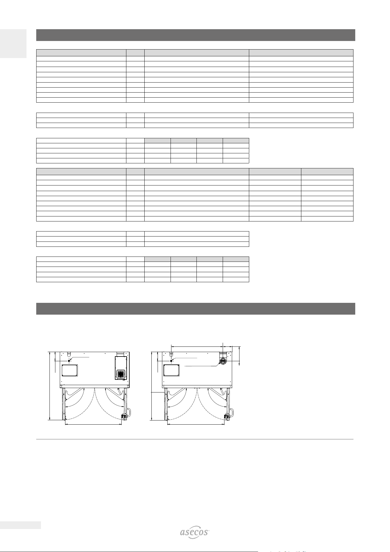
15. TECHNICAL DRAWING
15.1. ION-PRO-90
1167
966
89°
89°
156
Fresh air
884
1167
156
156
(155)
966
89°
89°
Fresh air
Exhaust air DN 75
IO90.195.120.PC.WDC IO90.195.120.PS.WDC
21
EN
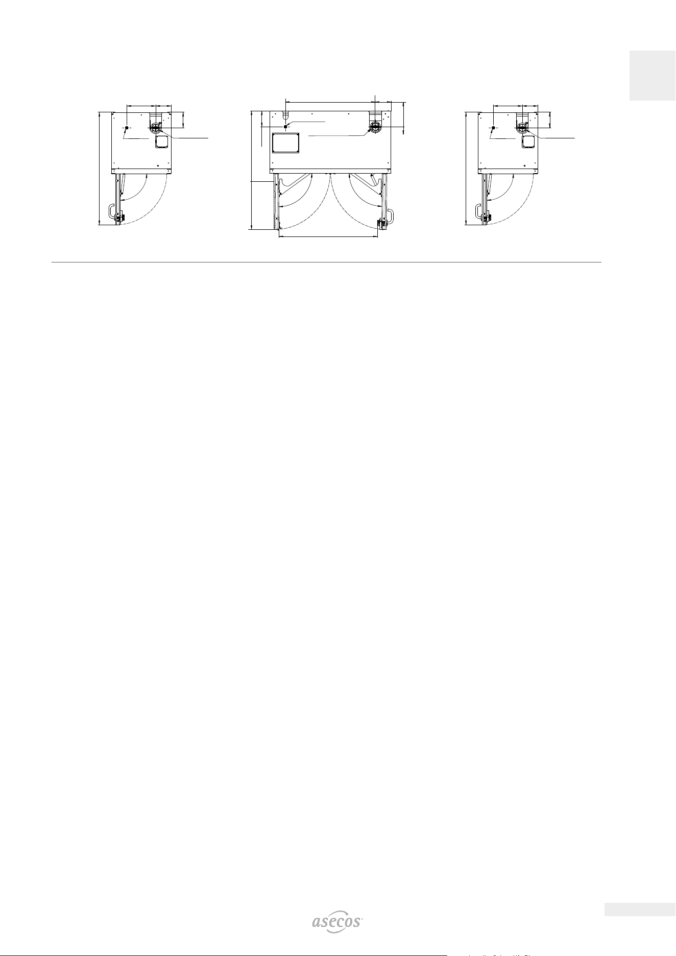
15.2. ION-CORE-90
290
1129
156
(155)
90°
Fresh air
Exhaust air DN
75
884
1167
156
156
(155)
966
89°
89°
Fresh air
Exhaust air DN 75
290
1129
156
(155)
90°
Fresh air
Exhaust air DN
75
IO90.195.060.CC.WDC IO90.195.120.CS.WDC IO90.195.060.CS.WDC

asecos GmbH
Sicherheit und Umweltschutz
Weiherfeldsiedlung 16–18
DE-63584 Gründau
+49 6051 92200
+49 6051 922010
asecos Ltd.
Safety and Environmental Protection
Profile House
Stores Road
Derby, Derbyshire
DE21 4BD
+44 1332 415933
asecos S.L.
Seguridad y Protección del
Medio Ambiente
C/ Calderí, s/n – Ed. CIM Vallés, planta 7,
oficinas 75-77
ES-08130 – Santa Perpètua de Mogoda
Barcelona
+34 935 745911
+34 935 745912
Asecos BV
Veiligheid en milieubescherming
Christiaan Huijgensweg 4
NL-2408 AJ Alphen a/d Rijn
+31 172 506476
+31 172 506541
asecos
Safety and Environmental Protection Inc.
c/o Schumann Burghart LLP
1500 Broadway, Suite 1902
NYC 10036, New York, USA
+1 727 251 9491
+49 6051 922010
asecos Schweiz AG
Sicherheit und Umweltschutz
Gewerbe Brunnmatt 5
CH-6264 Pfanau
+41 62 754 04 57
+41 62 754 04 58
asecos SARL
Sécurité et protection de l’environnement
7 rue du Pré Chaudron
FR-57070 Metz
+33 3 87 78 62 80
asecos AB
Säkerhet och miljöskydd
Skyttelgatan 23
753 42 Uppsala
+46 18 34 95 55

