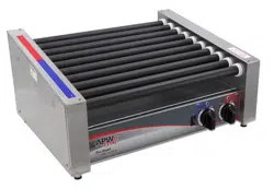
1
INSTALLATION AND OPERATING INSTRUCTIONS
HOTROD
®
ROLLER GRILLS
SLANTED HOTROD
®
ROLLER GRILLS
FULL MENU HOTROD
®
ROLLER GRILLS
Models: HR & HRS -31, -50, -45, -75 & -85 (BC, BD, BW, S, SBC, SBD,
SBW)
INTENDED FOR OTHER THAN HOUSEHOLD USE
WARNING: FOR YOUR SAFETY: Do not store or use gasoline or other ammable
vapors and liquids in the vicinity of this or any other appliance.
WARNING: Improper installation, operation, service or maintenance can cause
property damage, injury or death. Read and understand these instructions
thoroughly before positioning, installing, maintaining or servicing this equipment.
APW Wyott
®
cooking equipment has been engineered to provide you with year-round dependable
service when used according to the instructions in this manual and standard commercial
kitchen practices.
APW Wyott Food Service Equipment Company
265 Hobson St., Smithville, TN 37166
972.908.6100 Phone +1.800.527.2100
214.565.0976 Fax www.apwwyott.com
P/N 8893920 REV C 01/21
WARNING: California Residents Only. This product can expose you to chemicals including
chromium which is known to the State of California to cause cancer and birth defects or
other reproductive harm. For more information go to www.P65Warnings.ca.gov.
DESIGNED SMART. BUILT SOLID.
®

2
TABLE OF CONTENTS
Description Page
Safety Precautions .....................2
Specications .........................4
General Installation Instructions ...........5
Installation ............................6
Operation .............................6
Cleaning .............................6
Service ...............................7
Parts Lists & Exploded Views .............8
HR-31 & 50 BW (Exp View) .............8
HR-31 & 50 BC (Exp View) .............8
HR-31 & 50 (Exp View) ................9
Description ........................Page
HR-31 (Parts List) ....................10
HR-50 (Parts List) ....................11
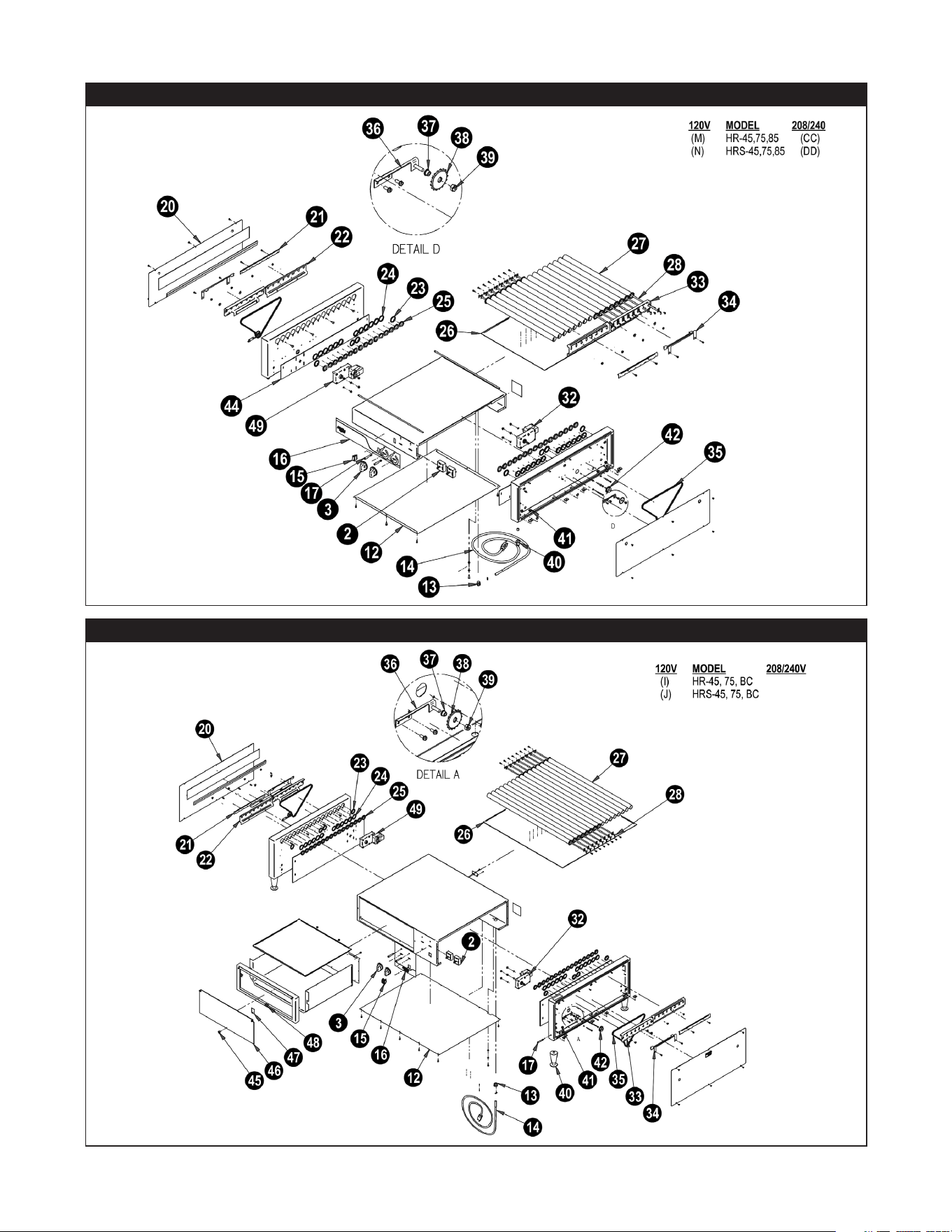
HR-45, 75 & 85 (Exp View) .............12
HR-45, 75 & 85 BC (Exp View) ..........12
HR-45, 75 & 85 BW (Exp View) .........13
HR-45 (Parts List) ....................14
HR-75 (Parts List) ....................15
HR-85 (Parts List) ....................16
Wiring Diagrams ......................17
Notes ...............................18
Warranty ............................19
APW Wyott takes pride in the design and quality of our products. When used as intended and with
proper care and maintenance, you will experience years of reliable operation from this equipment. To
ensure best results, it is important that you read and follow the instructions in this manual carefully.
Installation and start-up should be performed by a qualied installer who thoroughly read, understands
and follows these instructions.
If you have questions concerning the installation, operation, maintenance or service of this product,
contact APW Wyott Foodservice Equipment Company’s “ Technical Service Department”.
SAFETY PRECAUTIONS
Before installing and operating this equipment be sure everyone involved in its operation are fully
trained and are aware of all precautions. Accidents and problems can result by a failure to follow
fundamental rules and precautions.
The following words and symbols, found in this manual, alert you to hazards to the operator, service
personnel or the equipment. The words are dened as follows:
DANGER: This symbol warns of imminent hazard which will result in serious injury
or death.
WARNING: This symbol refers to a potential hazard or unsafe practice, which could
result in serious injury or death.
CAUTION: This symbol refers to a potential hazard or unsafe practice, which may
result in minor or moderate injury or product or property damage.
NOTICE: This symbol refers to information that needs special attention or must be
fully understood even though not dangerous.
CAUTION: These models are designed, built, and sold for commercial use. If these
models are positioned so the general public can use the equipment make sure that
cautions, warnings, and operating instructions are clearly posted near each unit so
that anyone using the equipment will use it correctly and not injure themselves or
harm the equipment.
WARNING: SHOCK HAZARD - Do not open any panels that require the use of tools.
3
WARNING: Improper installation, adjustment, alteration, service or maintenance
can cause property damage, injury or death. Read the Installation, Operating and
Maintenance Instructions thoroughly before installing or servicing this equipment.
NOTICE: The unit when installed, must be electrically grounded and comply with
local codes, or in the absence of local codes, with the national electrical code ANSI/
NFPA70- latest edition. Canadian installation must comply with CSA-STANDARD
C.22.2 Number 0 M1982 General Requirements-Canadian Electrical Code Part II,
109-M1981- Commercial Cooking Appliances.
NOTICE: Local codes regarding installation vary greatly from one area to another.
The National Fire Protection Association, Inc. states in its NFPA96 latest edition that
local codes are “Authority Having Jurisdiction” when it comes to requirement for
installation of equipment. Therefore, installation should comply with all local codes.
WARNING: Check the data plate on this unit before installation. Connect the unit
only to the voltage and frequency listed on the data plate. Connect only to 1 or 3
phase as listed on the data plate.
WARNING: Disconnect device from electrical power supply and place a Tag Out-
Lockout on the power plug, indicating that you are working on the circuit.
CAUTION: Maintenance & repair should be handled by a factory authorized agent.
Before doing any maintenance or repair, contact APW Wyott.
NOTICE: Install according to the spacing requirements listed in the installation
section of this manual. We strongly recommend having a competent professional
install this equipment. A licensed electrician should make the electrical connections
and connect power to the unit. Local codes should always be used when
connecting these units to electrical power. In the absence of local codes, use the
latest version of the National Electrical Code.
Location of Data Plate
The data plate for the HotRod
®
Roller Grill is located on the back of the unit.
Immediately Inspect for Shipping Damage
All containers should be examined for damage before and during unloading. The freight carrier has
assumed responsibility for its safe transit and delivery. If equipment is received damaged, either
apparent or concealed, a claim must be made with the delivering carrier.
A. Apparent damage or loss must be noted on the freight bill at the time of delivery. It must then be
signed by the carrier representative (Driver). If this is not done, the carrier may refuse the claim. The
carrier can supply the necessary forms.
B. Concealed damage or loss if not apparent until after equipment is uncrated, a request for
inspection must be made to the carrier within 15 days. The carrier should arrange an inspection.
Be certain to hold all contents and packaging material.
Installation and start-up should be performed by a qualied installer who thoroughly read, understands
and follows these instructions.

4
SPECIFICATIONS
Model Width Depth Height Voltage AMPS
HR-31 23.75” 18.625” 9.125” 120 8.3
HR-31BC 23.75” 18.625” 13.1875” 120 8.3
HR-31BD 23.75” 18.625” 13.1875” 120 8.3
HR-31BW 23.75” 18.625” 13.1875” 120 8.3
HRS-31 23.75” 18.625” 9.125” 120 8.3
HRS-31BC 23.75” 18.625” 13.1875” 120 8.3
HRS-31BD 23.75” 18.625” 13.1875” 120 8.3
HRS-31BW 23.75” 18.625” 13.1875” 120 8.3
HR-31S 23.75” 18.375” 11.75” 120 8.3
HR-31SBC 23.75” 18.375” 16.125” 120 8.3
HR-31SBD 23.75” 18.375” 16.125” 120 8.3
HR-31SBW 23.75” 18.375” 16.125” 120 8.3
HRS-31S 23.75” 18.375” 11.75” 120 8.3
HRS-31SBC 23.75” 18.375” 16.125” 120 8.3
HRS-31SBD 23.75” 18.375” 16.125” 120 8.3
HRS-31SBW 23.75” 18.375” 16.125” 120 8.3
HR-31 23.75 18.625 9.125 208/240 4.8/4.2
HR-50 34.75” 18.625” 9.125” 120 11
HR-50BC 34.75” 18.625” 13.1875” 120 11
HR-50BD 34.75” 18.625” 13.1875” 120 11
HR-50BW 34.75” 18.625” 13.1875” 120 11
HRS-50 34.75” 18.625” 9.125” 120 11
HRS-50BC 34.75” 18.625” 13.1875” 120 11
HRS-50BD 34.75” 18.625” 13.1875” 120 11
HRS-50BW 34.75” 18.625” 13.1875” 120 11
HR-50S 34.75” 18.375” 11.75” 120 11
HR-50SBC 34.75” 18.375” 16.125” 120 11
HR-50SBD 34.75” 18.375” 16.125” 120 11
HR-50SBW 34.75” 18.375” 16.125” 120 11
HRS-50S 34.75” 18.375” 11.75” 120 11
HRS-50SBC 34.75” 18.375” 16.125” 120 11
HRS-50SBD 34.75” 18.375” 16.125” 120 11
HRS-50SBW 34.75” 18.375” 16.125” 120 11
HR-45 23.75” 29.56” 10.875” 120 12.2
HR-45BC 23.75” 29.56” 13.75” 120 12.2
HR-45BW 23.75” 29.56” 13.75” 120 12.2
HRS-45BC 23.75” 29.56” 13.75” 120 12.2
HRS-45BW 23.75” 29.56” 13.75” 120 12.2
HR-75 34.75” 29.56” 10.875” 120 16.6
HR-75BC 34.75” 29.56” 16.75” 120 16.6
HR-75BW 34.75” 29.56” 16.75” 120 16.6
HRS-75BC 34.75” 29.56” 16.75” 120 16.6
HRS-75BW 34.75” 29.56” 16.75” 120 16.6
HR-85BW 34.75” 29.56” 16.75” 120 18.7
HRS-85BW 34.75” 29.56” 16.75” 120 18.7
5
GENERAL INSTALLATION INSTRUCTIONS
This unit has been inspected and tested at the factory prior to shipment.
Unpack the unit and remove all packing materials. Place on a at horizontal surface at the desired
location.
WARNING: Check the data plate on this unit before installation. Connect the unit
only to the voltage and frequency listed on the data plate. Connect only to 1 or 3
phase as listed on the data plate.
WARNING: IMPROPER GROUNDING COULD RESULT IN ELECTRICAL SHOCK!
This appliance is equipped with a three prong (grounded) plug for your protection
against electrical shock hazard and should be plugged directly into a properly
grounded three prong receptacle. Do not cut or remove the grounding prong from
this plug.
CAUTION: Do not use ordinary steel wool as any particles left on the surface will
rust.
NEVER USE a wire brush, steel or abrasive scouring pads (except stainless), scraper, le or other steel
tools. Surfaces which are marred collect dirt more rapidly and become more dicult to clean. Marring
also increases the possibility of corrosive attack.
NEVER use any corrosive cleaner. Use only cleaners approved for stainless steel.
NEVER use cleaning solvents with a hydrocarbon base.
General Installation:
1. Always clean equipment thoroughly before rst use. (See general cleaning instructions)
2. Check ratings label for your model designation and electrical ratings.
3. For best results, use stainless steel countertops.
4. Attach legs to unit.
General Operation Instructions:
1. Trained personnel should operate all food service equipment.
2. Do not allow your customers to come into contact with any surface labeled “CAUTION HOT”.
3. Where applicable, never pour cold water into dry heated units.
4. Where applicable, do not cook, warm or hold food directly in liner/well pans. Always use steam
table pans/inserts, etc.
5. NEVER hold food below 140° F.
General Cleaning Instructions:
1. Never clean any electrical unit by immersing it in water. Turn the unit o and allow it to cool before
surface cleaning.
2. Always clean equipment thoroughly before rst use. Clean unit daily. Except where noted on
charts: use warm, soapy water. Mild cleansers and plastic scouring pads may be used to remove
baked-on food and water scale on metal unit. NOTE: do not clean roller tubes with abrasive
cleaners or scouring pads. Follow instructions on page 6.
3. Unplug electrical unit before cleaning or servicing. All service should be performed by an
APW Wyott authorized service agency.

6
General Troubleshooting:
Always ask and check:
1. Is the unit connected to a live power source?
2. Check the circuit breaker.
3. Is power switch on and pilot light glowing?
4. Check the rating label. Are you operating unit on the proper voltage?
If the above checks out and you still have problems, call an APW Wyott authorized service agency.
INSTALLATION
Place the HOTROD
®
directly on a countertop or on a matching APW Wyott Bun Warmer or Bun
Cabinet (available separately). Place the unit close to an AC outlet, of the correct voltage, to avoid
undue strain on the power cord.
CAUTION: To avoid equipment damage, make certain that the nameplate voltage is
the same as the outlet voltage.
If the plug is to be removed and replaced with a plug more suitable for your area, the color code for
the power cable is:
Neutral (N) = White or Blue Live (l) = Black or Brown Safety Earth (E) = Green or Yellow/Green
After a suitable location has been chosen, wipe the rollers and the drip pan with a damp cloth. The
unit is ready for use.
OPERATION
WARNING: This unit is not intended to hold potentially hazardous foods such as
un-cooked or un-preserved meats and sausages.
There are three simple controls on the front of this unit: a switch, which controls the tube rotation, and
two adjustable heat controls, which activates the two banks of heating elements in the roller tubes.
Both heat controls have a light above them indicating either “Front’ or “Back”. The front heat control
activates the rst 5 or 6 (depending on if your unit has 10 or 11 tubes). The back Control activates the
remaining 5 tubes. Each bank of tubes can be heated independently of the others and at separate
temperature settings. Variations in voltage and ventilation make experimenting the best guide to
power level adjustment.
When a preferred adjustment is found, and it is desired to return consistently to the same spot on the
controls, the controls can be ne-tuned by aligning with a mark on the knob. This adjustment does not
require a service visit.
CLEANING
Daily Cleaning Instructions:
1. Heat the unit.
2. Using a moist cloth lled with crushed or aked ice, wipe each tube. Wipe the tubes from each
end to the center. This will keep as much of the loosened particles out of the bearings as possible.
Extend the cloth as far as possible between the rollers.
3. With the heated rollers wiped with an ice lled cloth to loosen the particles, now, wipe clean with
another cloth. Continue to wipe from the end of the rollers to the center. This will reduce the grease
and partials getting into the bearings and drive mechanism. This will extend the life of the unit and
extend the period between routine maintenance of the drive mechanism.
CAUTION: NEVER use abrasive powders or pads; these cleaners may damage the
roller nish. Also, the particles may get into the drive mechanism shortening the unit life.

7
4. Remove the drip pan and wash it in hot, soapy water, then rinse.
5. If stains are still present, add a light detergent to the cloth and repeat.
6. Replace the pan and turn the unit o if the grill will not be immediately used.
Alternate Cleaning Method using optional 3M sponge (#21807305) and cleaning handle (#21807300):
1. Turn heat down to lower setting (i.e. “hold” temperature) and allow grill to cool.
2. If the grill has considerable grease build-up, wipe the excess grease from the rollers with a lint free
towel or paper towel before using the soap and sponge.
3. Place sponge onto cleaning handle.
4. Immerse sponge in warm, soapy water.
5. Scrub rollers starting from the outside of the roller working your way to the center. Rinse sponge
and re-wet with the soapy solution as needed.
6. Ensure that entire roller surface is cleaned.
7. Dry with a lint free towel or paper towel.
NOTE: Cleanup will be faster if the product is specically made for cooking on roller
grills. Several meat packers now oer this product. For high-volume applications
or for products that have a high sugar or fat content, the HOTROD
®
Roller Grill may
require more frequent cleaning. For longer life of your HOTROD
®
Roller Grill, follow
instructions for periodic cleaning throughout the day.
Periodic Cleaning Throughout The Day:
1. For high-volume applications or for product that has a high fat content clean the rollers every 3-4
hours.
2. Clean by removing the product from the rollers and wiping with a damp cloth from outside end of
the rollers to the center. Replace the product and continue cooking. There should be no need to
turn o the heat when wiping down the rollers. But care should be taken not to bring hands into
direct contact with the rollers as a burn could result.
NOTE: This appliance shall not be cleaned with a water jet.
SERVICE
Service work should be performed only by a qualied technician who is experienced in and
knowledgeable with the operation of commercial gas, electric, steam cooking equipment. Contact the
Authorized Service Agency for reliable service, dependable advice or other assistance and for genuine
factory parts.
IF THE SUPPLY CORD IS DAMAGED, IT MUST BE REPLACED BY THE MANUFACTURER OR ITS
SERVICE AGENT OR A SIMILARLY QUALIFIED PERSON IN ORDER TO AVOID A HAZARD.
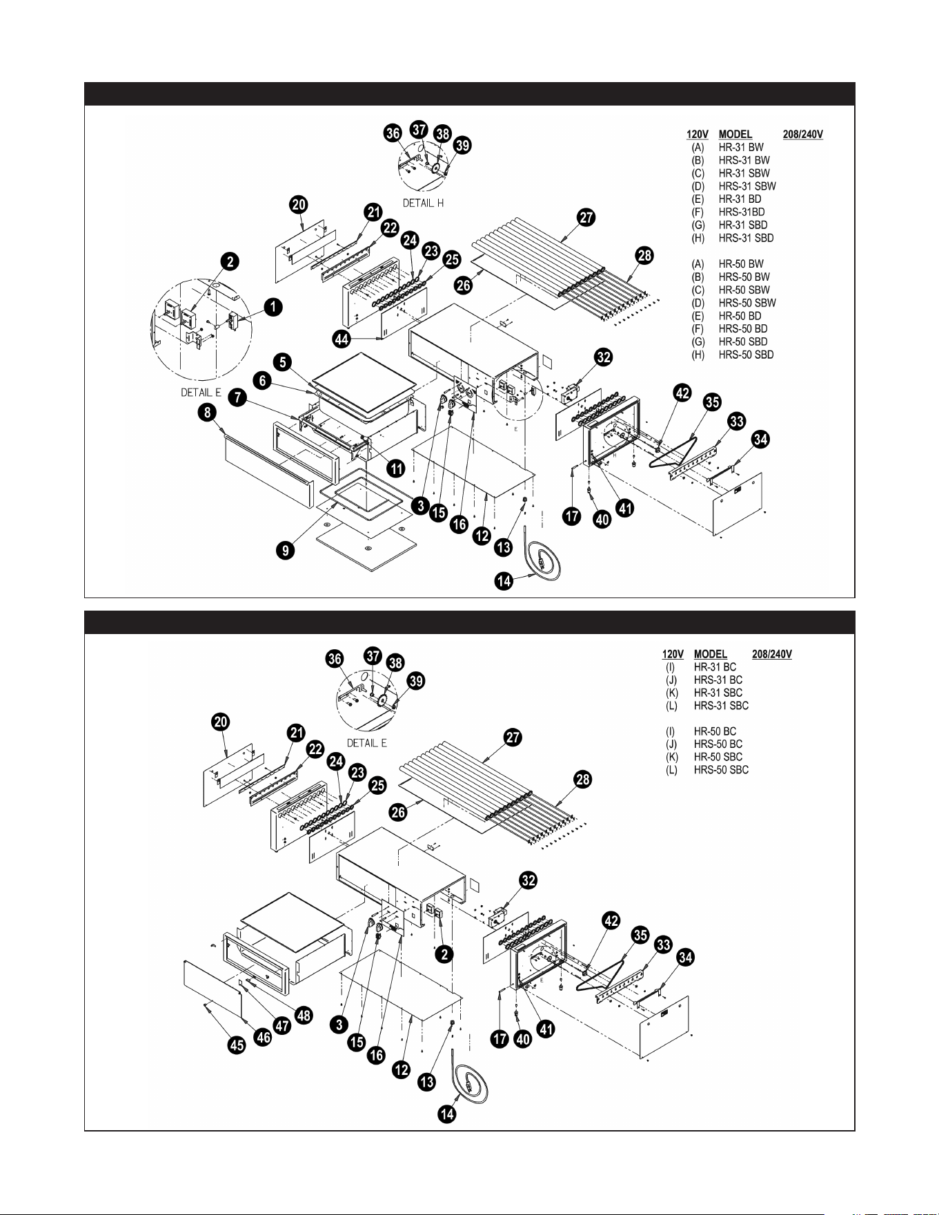
8
EXPLODED VIEW – HR-31 & 50 BW
EXPLODED VIEW – HR-31 & 50 BC
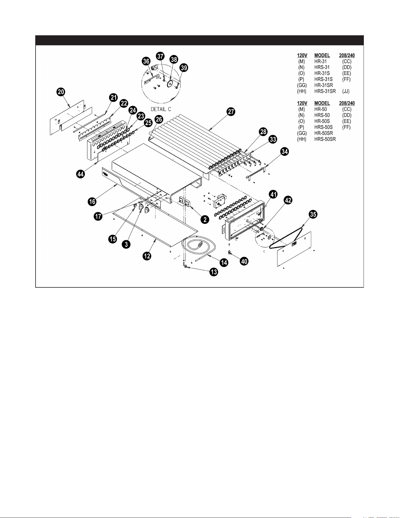
9
EXPLODED VIEW – HR-31 & 50

10
P/N Description
Qty Used On
1 1481510 Thermostat
1 A B C D
2 1327900 Innite Switch
2 A B C D E F G H I J K L M N O P GG HH
2 1328200 Innite Switch
2 CC DD EE FF JJ
3 8705610 Knob
2 A B C D E F G H I J K L M N O P CC DD EE FF GG HH JJ
5 21794621 Pan, Cover
1 A B C D E F G H
6 2421600 Pan, 2/3 6” Deep
1 A B C D E F G H
7 21794619 Weldm’t, Drawer Frame
1 A B C D E F G H
8 21834618 Drawer, Front HR-31
1 A B C D E F G H
9 1431101 Heater, Rope 200W 120V
1 A B C D
9 1431113 Heater, Rope 200W 208V
1
11 8641500 Bearings, Stainless Roller Slides
4 A B C D E F G H
12 21807405 Bottom, HR-31
1 A B C D E F G H I J K L
12 21771411 Bottom, HR-31
1 M N O P CC DD EE FF GG HH JJ
13 8967400 Strain Relief Right Angle
1 A B C D E F G H I J K L
13 8968900 Strain Relief Right Angle
1 M N O P CC DD EE FF GG HH JJ
14 1542002 Cordset, 5-15P 14/3 90C SJO
1 M N O P
14 1532500 Cordset, SJTO 16-3
1 A B C D E F G H I J K L
14 1542005 Cordset, 14/3 500C W/NEMA 6-15P
1 CC DD EE FF JJ
14 782068 Cordset, 12/3 SJTOW NEMA 5-20P
1
15 1331800 Switch Rocker
1 M N O P CC DD EE FF
15 47591400 Switch Rocker
1 A B C D E F G H I J K L GG HH JJ
16 21808154 Decal, HR-31 & 45BW
1 A B C D
16 21807654 Decal, HR-31BD & BC
1 E F G H I J K L
16 8815600 Decal, HR-31Front Panel
1 M N O P CC DD EE FF GG HH JJ
17 1513903 Light, Indicator, 250V
1 A B C D E F G H I J K L
18 21797415 Panel, End L.H. Slant
1 C D G H K L
18 21749520 Panel, Left Slant HR
1 O P EE FF JJ
19 21797414 Panel, End R.H. Slant
1 C D G H K L
19 21749510 Panel, Right Slant HR
1 O P EE FF JJ
20 21833914 Panel, End
2 A B E F I J
20 21747001 Panel, End
2 M N CC DD GG HH
21 21794611 Heater Retainer, Front
1 A B E F I J CC DD GG HH
21 21748100 Heater Retainer, Front
1 M N O P GG HH JJ
21 21795111 Heater Retainer, Front Slant
1 C D G H K L EE FF
22 21794609 Element Support
1 A B E F
22 21748000 Support, Element
1 M N CC DD GG HH
22 21794609 Support, Element
1 A B E F I J
22 21795109 Support, Element Slant
1 C D G H K L
22 21771025 Support, Element Slant
1 O P EE FF JJ
23 21793400 Bearing, Hot Rod
4 A B C D E F G H I J K L M N O P CC DD EE FF GG HH JJ
24 21748900 Bearing, Hot Rod
V. A B C D E F G H I J K L M N O P CC DD EE FF GG HH JJ
25 422300 Seal, Grease
V. A B C D E F G H I J K L M N O P CC DD EE FF GG HH JJ
26 21771412 Pan, Drip HR-31
1 A B C D E F G H I J K L M N O P CC DD EE FF GG HH JJ
27 21771429 Roller Tube-31 Plated
V. A C E G I K M O CC EE HH JJ
27 21771418 Roller Tube-31 Xylan Coating
V. B D F H J L N P DD FF GG
28 1431532 Element, HR-31 120V
V. A B C D E F G H I J K L M N O P GG HH JJ
28 1431533 Element, HR-31 220V, 115W
V. CC DD EE FF
32 1212000 Motor, Gear 110V, 60HZ
1 A B C D E F G H I J K L M N O P GG HH JJ
32 1211700 Motor, Gear 240V 50-60HZ
1 CC DD EE FF
33 21748303 Chain Guide Bracket
1 A B E F I J M N CC DD GG HH
33 21771016 Chain Guide Bracket
1 C D G H K L O P EE FF JJ
34 21748312 Bracket, Gage
1 A B E F I J M N GG HH
34 21771017 Bracket, Gage
1 C D G H K L O P JJ
35 21748505 Chain
1 A B E F I J M N CC DD GG HH
35 21748511 Chain Drive HR Slant, Wide Spacing
1 C D G H K L O P EE FF JJ
36 21792309 Tensioner
1 A B C D E F G H I J K L M N O P CC DD EE FF GG HH JJ
37 21792308 Bushing
1 A B C D E F G H I J K L M N O P CC DD EE FF GG HH JJ
38 21748501 Sprocket
1 A B C D E F G H I J K L M N O P CC DD EE FF GG HH JJ
39 8414700 Nut #10-32
1 A B C D E F G H I J K L M N O P CC DD EE FF GG HH JJ
40 8662100 Leg, 1” Chrome
4 A B C D E F G H I J K L M N O P GG HH JJ
41 8966400 Bushing, Snap HEYCO #2820
V. A B C D E F G H I J K L M N O P CC DD EE FF GG HH JJ
42 21748510 Sprocket, 17 Tooth w/Hub
1 A B C D E F G H I J K L M N O P CC DD EE FF GG HH JJ
43 21750710 Insulation, Left side CHAIO TAI HR
1 M N O P CC DD EE FF GG HH JJ
44 21838116 Insulation, HR
2 A B C D E F G H I J K L
44 21750700 Insulation, HR Motor Side
1 M N O P CC DD EE FF GG HH JJ
45 8702000 Knob, 8-32Thread
1 I J K L
46 21794643 Door, BC-31
1 I J K L
47 21749953 Plate, Strike
1 I J K L
48 8705000 Magnet
1 I J K L
HR-31 PARTS LIST

11
P/N Description Qty Used On
1 1481510 Thermostat 1
A B C D
2 1327900 Innite Switch 2
A B C D E F G H I J K L M N O P GG HH JJ
2 1328200 Innite Switch 2
CC DD EE FF
3 8705610 Knob 2
A B C D E F G H I J K L M N O P CC DD EE FF GG HH JJ
5 21794621 Pan, Cover 1
A B C D E F G H
6 2421600 Pan, 2/3 6” Deep 1
A B C D E F G H
7 21794619 Weldm’t, Drawer Frame 1
8 21834618 Drawer, Front HR-50 1
A B C D E F G H
9 1431101 Heater, Rope 200W 120V 1
A B C D
9 1431113 Heater, Rope 200W 208V 1
11 8641500 Bearings, Stainless Roller Slides 4
A B C D E F G H
12 21807405 Bottom, HR-50 1
A B C D E F G H I J K L
12 21771411 Bottom, HR-50 1
M N O P CC DD EE FF GG HH JJ
13 8967400 Strain Relief Right Angle 1
A B C D E F G H I J K L
13 8968900 Strain Relief Right Angle 1
M N O P CC DD EE FF GG HH JJ
14 1542002 Cordset,5-15P14/390CSJO 1
M N O P GG HH
14 1532500 Cordset, SJTO 16-3 1
A B C D E F G H I J K L
14 1542005 Cordset,14/3500CW/NEMA6-15P 1
CC DD EE FF JJ
14 782068 Cordset, 12/3 SJTOW NEMA 5-20P 1
15 1331800 Switch Rocker 1
M N O P CC DD EE FF
15 47591400 Switch Rocker 1
A B C D E F G H I J K L GG HH JJ
16 21808154 Decal, HR-31 & 45BW 1
A B C D
16 21807655 Decal, HR-50BD & BC 1
E F G H I J K L
16 8816550 Decal, HR-50 Front Panel 1
M N O P CC DD EE FF GG HH JJ
17 1513903 Light, Indicator, 250V 1
A B C D E F G H I J K L
18 21797415 Panel, End L.H. Slant 1
C D G H K L
18 21749520 Panel, Left Slant HR 1
O P EE FF JJ
19 21797414 Panel, End R.H. Slant 1
C D G H K L
19 21749510 Panel, Right Slant HR 1
O P EE FF JJ
20 21833914 Panel, End 2
A B E F I J
20 21747001 Panel, End 2
M N CC DD GG HH
21 21794611 Heater Retainer, Front 1
A B E F I J CC DD GG HH
21 21748100 Heater Retainer, Front 1
M N O P GG HH JJ
21 21795111 Heater Retainer, Front Slant 1
C D G H K L EE FF
22 21794609 Element Support 1
A B E F
22 21748000 Support, Element 1
M N CC DD GG HH
22 21794609 Support, Element 1
A B E F I J
22 21795109 Support, Element Slant 1
C D G H K L
22 21771025 Support, Element Slant 1
O P EE FF JJ
23 21793400 Bearing, Hot Rod 4
A B C D E F G H I J K L M N O P CC DD EE FF GG HH JJ
24 21748900 Bearing, Hot Rod V.
A B C D E F G H I J K L M N O P CC DD EE FF GG HH JJ
25 422300 Seal, Grease V.
A B C D E F G H I J K L M N O P CC DD EE FF GG HH JJ
26 21748450 Pan, Drip HR-50 1
A B C D E F G H I J K L M N O P CC DD EE FF GG HH JJ
27 21752380 Roller Tube-50 Plated V.
A C E G I K M O CC EE HH JJ
27 21752370 Roller Tube-50 Xylan Coating V.
B D F H J L N P DD FF GG
28 1431532 Element, HR-50 120V V.
A B C D E F G H I J K L M N O P GG HH JJ
28 1431450 Element, HR-50 220V, 115W V.
CC DD EE FF
32 1212000 Motor, Gear 110V, 60HZ 1
A B C D E F G H I J K L M N O P GG HH JJ
32 1211700 Motor, Gear 240V 50-60HZ 1
CC DD EE FF
33 21748303 Chain Guide Bracket 1
A B E F I J M N CC DD GG HH
33 21771016 Chain Guide Bracket 1
C D G H K L O P EE FF JJ
34 21748312 Bracket, Gage 1
A B E F I J M N GG HH
34 21771017 Bracket, Gage 1
C D G H K L O P JJ
35 21748505 Chain 1
A B E F I J M N CC DD GG HH
35 21748511 Chain Drive HR Slant, Wide Spacing 1
C D G H K L O P EE FF JJ
36 21792309 Tensioner 1
A B C D E F G H I J K L M N O P CC DD EE FF GG HH JJ
37 21792308 Bushing 1
A B C D E F G H I J K L M N O P CC DD EE FF GG HH JJ
38 21748501 Sprocket 1
A B C D E F G H I J K L M N O P CC DD EE FF GG HH JJ
39 8414700 Nut #10-32 1
A B C D E F G H I J K L M N O P CC DD EE FF GG HH JJ
40 8662100 Leg, 1”Chrome 4
A B C D E F G H I J K L M N O P GG HH JJ
41 8966400 Bushing, Snap HEYCO #2820 V.
A B C D E F G H I J K L M N O P CC DD EE FF GG HH JJ
42 21748510 Sprocket, 17 Tooth w/Hub 1
A B C D E F G H I J K L M N O P CC DD EE FF GG HH JJ
43 21750710 Insulation, Leftside CHAIO TAI HR 1
M N O P CC DD EE FF GG HH JJ
44 21838116 Insulation, HR 2
A B C D E F G H I J K L
44 21750700 Insulation, HR Motor Side 1
M N O P CC DD EE FF GG HH JJ
45 8702000 Knob, 8-32 Thread 1
I J K L
46 21794643 Door, BC-50 1
I J K L
47 21749953 Plate, Strike 1
I J K L
48 8705000 Magnet 1
I J K L
HR-50 PARTS LIST
12
EXPLODED VIEW – HR-45, 75 & 85
EXPLODED VIEW – HR-45 & 75 & 85 BC
13
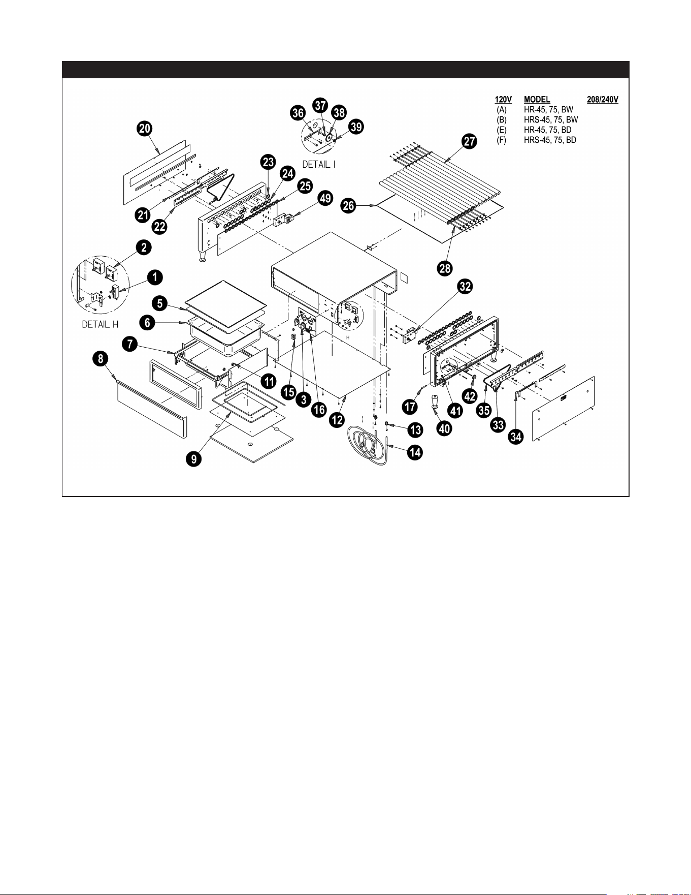
EXPLODED VIEW – HR-45, 75 & 85 BW

14
Item P/N Description Qty Used On
1 1481510 Thermostat 1 A B
2 1327900 Innite Switch 2 A B I J M N
2 1328200 Innite Switch 2
3 8705610 Knob 2 A B I J M N
5 21794821 Pan, Cover HR-45BWE 1 A B
6 2420200 Pan,12x20x6 Deep 1 A B
7 21794619 Weldm’t, Drawer Frame 1
8 21794818 Drawer, Front HR-45 1 A B
9 1431102 Heater, Rope, 84” 300W 120V 1 A B
9 1431113 Heater, Rope 200W 208V 1
11 8641500 Bearings, Stainless Roller Slides 4 A B
12 21807805 Bottom, HR-45 1 A B I J
12 21771421 Bottom, HR-45 1 M N
13 8967501 Strain Relief 12/3 1 A B
13 8968900 Strain Relief Right Angle 1 I J M N
14 1542002 Cordset,5-15P14/390CSJO 1 I J M N
14 1532500 Cordset, SJTO 16-3 1
14 1542005 Cordset,14/3500CW/NEMA6-15P 1
14 782068 Cordset, 12/3 SJTOW NEMA 5-20P 1 A B
15 1331800 Switch Rocker 1 M N
15 47591400 Switch Rocker 1 A B I J
16 21808154 Decal, HR-45BW 1 A B
16 21807654 Decal, HR-31BD & BC 1 I J
16 8815600 Decal, HR-31 Front Panel 1 M N
17 1513903 Light, Indicator, 250V 1 A B I J
20 21807814 Panel, End 2 A B I J
20 21752465 Panel, End 2 M N
21 21792239 Heater Retainer, Front 1 A B I J M N
21 21748100 Heater Retainer, Front 1
22 21792234 Element Support 1 A B I J M N
22 21807888 Support, Element Rope Heater 1
22 21794609 Support, Element 1
23 21793400 Bearing, Hot Rod 4 A B I J M N
24 21748900 Bearing, Hot Rod V. A B I J M N
25 422300 Seal, Grease V. A B I J M N
26 21771420 Pan, Drip HRS-45 1 A B I J M N
27 21771429 RollerTube-31Plated V. A I M
27 21771418 Roller Tube-31 Xylan Coating V. B J N
28 1431532 Element, HR-31120V V. A B I J M N
32 1212000 Motor, Gear 110V, 60HZ 1 A B I J M N
32 1211700 Motor, Gear 240V 50-60HZ 1
33 21792336 Chain Guide Bracket 1 A B I J M N
33 21771016 Chain Guide Bracket 1
34 21748312 Bracket, Gage 1 A B I J M N
34 21771017 Bracket, Gage 1
35 21792251 Chain 1 A B I J M N
36 21792309 Tensioner 1 A B I J M N
37 21792308 Bushing 1 A B I J M N
38 21748501 Sprocket 1 A B I J M N
39 8414700 Nut #10-32 1 A B I J M N
40 8662100 Leg, 1”Chrome 4 A B I J M N
41 8966400 Bushing, Snap HEYCO#2820 V. A B I J M N
42 21748510 Sprocket, 17 Tooth w/Hub 1 A B I J M N
43 21750710 Insulation, HR-45-75-85 1 M N
44 21807816 Insulation, HR RightSide 1 A B I J
44 21807817 Insulation, HR LeftSide 1 A B I J
45 8702000 Knob, 8-32Thread 1 I J
46 21794643 Door, BC-31 1 I J
47 21749953 Plate, Strike 1 I J
48 8705000 Magnet 1 I J
49 1212300 Motor, Gear 110V, 60HZ 1 A B I J M N
HR-45 PARTS LIST

15
HR-75 PARTS LIST
Item P/N Description Qty Used On
1 1481510 Thermostat 1 A B
2 1327900 Innite Switch 2 A B I J M N
2 1328200 Innite Switch 2 CC DD
3 8705610 Knob 2 A B I J M N CC DD
5 21792221 Pan, Cover HR-45 BWE 1 A B
6 2421401 Pan, Modied 1 A B
7 21794619 Weldm’t, Drawer Frame 1
8 21833918 Drawer, Front 1 A B
9 1431105 Heater, Rope, 108” 400W 120V 1 A B
9 1431113 Heater, Rope 200W 208V 1
11 8641500 Bearings, Stainless Roller Slides 4 A B
12 21792205 Bottom Cover 1 A B I J
12 21771461 Bottom Cover 1 M N CC DD
13 8968900 Strain Relief 90 deg 1 CC DD
13 8967500 Strain Relief 14/3 1 A B
13 8967501 Strain Relief 12/3 1 I J
13 8967400 Strain Relief 1 M N
14 1542002 Cordset, 5-15P14/390CSJO 1
14 1532500 Cordset, SJTO 16-3 1 M N
14 1542005 Cordset, 14/3 500C W/NEMA 6-15P 1 CC DD
14 1537000 Cordset, 14-3NEMA5-15P 1 A B
14 782068 Cordset, 12/3 SJTO W/NEMA 5-20P 1 I J
15 1331800 Switch Rocker 1 M N CC DD
15 47591400 Switch Rocker 1 A B I J
16 21808155 Decal, HR-50BW 1 A B
16 21807655 Decal, HR-50BC 1 I J
16 8816550 Decal, HR-50 Front Panel 1 M CC DD
17 1513903 Light, Indicator, 250V 1 A B I J M CC DD
20 21807814 Panel, End 2 A B I J
20 21752465 Panel, End 2 M CC DD
21 21792239 Heater Retainer, Front 1 A B I J M CC DD
21 21748100 Heater Retainer, Front 1
22 21792234 Element Support 1 A B I J M CC DD
22 21807888 Support, Element Rope Heater 1
22 21794609 Support, Element 1
23 21793400 Bearing, Hot Rod 4 A B I J M CC DD
24 21748900 Bearing, Hot Rod V. A B I J M CC DD
25 422300 Seal, Grease V. A B I J M CC DD
26 21752488 Pan, Drip 1 A B I J M CC DD
27 21752380 Roller Tube-31 Plated V. A I M CC
27 21752370 Roller Tube-31 Xylan Coating V. B J DD
28 1431550 Element, HR-50 120V V. A B I J M
32 1212000 Motor, Gear 110V, 60HZ 1 A B I J M
32 1211700 Motor, Gear 240V 50-60HZ 1 CC DD
33 21792336 Chain Guide Bracket 1 A B I J M CC DD
33 21771016 Chain Guide Bracket 1
34 21748312 Bracket, Gage 1 A B I J M
34 21771017 Bracket, Gage 1
35 21792251 Chain Drive 33-3/4” J36P 1 A B I J M CC DD
36 21792309 Tensioner 1 A B I J M CC DD
37 21792308 Bushing 1 A B I J M CC DD
38 21748501 Sprocket 1 A B I J M CC DD
39 8414700 Nut #10-32 1 A B I J M CC DD
40 8632000 Leg, 4” ADJ, 2000lbCap 4 A B I J M
40 8662100 Leg, 1” Chrome 4 M CC DD
41 8966400 Bushing, Snap HEYCO #2820 V. A B I J M CC DD
42 21748510 Sprocket, 17 Tooth w/Hub 1 A B I J M CC DD
43 21750715 Insulation, HR-45-75-85 1 M CC DD
44 21807816 Insulation, HR RightSide 1 A B I J
44 21807817 Insulation, HR LeftSide 1 A B I J
45 8702000 Knob, 8-32 Thread 1 I J
46 21795618 Bun Cabinet Door 1 I J
47 21749953 Plate, Strike 1 I J
48 8705000 Magnet 1 I J
49 1211800 Motor, Gear 240V 50-60HZ 1 CC DD
49 1212300 Motor, Gear 110V, 60HZ 1 A B I J M

16
HR-85 PARTS LIST
Item P/N Description Qty Used On
1 1481510 Thermostat 1
2 1327900 Innite Switch 2
2 1328200 Innite Switch 2 CC DD
3 8705610 Knob 2 CC DD
5 21792221 Pan, Cover HR-45 BWE 1
6 2421401 Pan, Modied 1
7 21794619 Weldm’t, Drawer Frame 1
8 21833918 Drawer, Front 1
9 1431105 Heater, Rope, 108” 400W 120V 1
9 1431113 Heater, Rope 200W 208V 1
11 8641500 Bearings, Stainless Roller Slides 4
12 21792205 Bottom Cover 1
12 21771461 Bottom Cover 1 CC DD
13 8968900 Strain Relief 90 deg 1 CC DD
13 8967500 Strain Relief 14/3 1
13 8967501 Strain Relief 12/3 1
13 8967400 Strain Relief 1
14 1542002 Cordset, 5-15P14/390CSJO 1
14 1532500 Cordset, SJTO 16-3 1
14 1542005 Cordset, 14/3 500C W/NEMA 6-15P 1 CC DD
14 1537000 Cordset, 14-3 NEMA5-15P 1
14 782068 Cordset, 12/3 SJTOWNEMA5-20P 1
15 1331800 Switch Rocker 1 CC DD
15 47591400 Switch Rocker 1
16 21808155 Decal, HR-50BW 1
16 21807655 Decal, HR-50BC 1
16 8816550 Decal, HR-50 Front Panel 1 CC DD
17 1513903 Light, Indicator, 250V 1 CC DD
20 21807814 Panel, End 2
20 21752465 Panel, End 2 CC DD
21 21778135 Heater Retainer, Front 1 CC DD
21 21748100 Heater Retainer, Front 1
22 21778134 Element Support 1 CC DD
22 21807888 Support, Element Rope Heater 1
22 21794609 Support, Element 1
23 21793400 Bearing, Hot Rod 4 CC DD
24 21748900 Bearing, Hot Rod V. CC DD
25 422300 Seal, Grease V. CC DD
26 21752488 Pan, Drip 1 CC DD
27 21752380 Roller Tube-31 Plated V. CC
27 21752370 Roller Tube-31 Xylan Coating V. DD
28 1431550 Element, HR-50 120V V.
32 1212000 Motor, Gear 110V, 60HZ 1
32 1211700 Motor, Gear 240V 50-60HZ 1 CC DD
33 21832492 Chain Guide Bracket, HR-85 1 CC DD
33 21771016 Chain Guide Bracket 1
34 21748312 Bracket, Gage 1
34 21771017 Bracket, Gage 1
35 21748507 Chain Drive 34-1/2” J38P 1 CC DD
36 21792309 Tensioner 1 CC DD
37 21792308 Bushing 1 CC DD
38 21748501 Sprocket 1 CC DD
39 8414700 Nut #10-32 1 CC DD
40 8632000 Leg, 4” ADJ, 2000lb Cap 4
40 8662100 Leg, 1” Chrome 4 CC DD
41 8966400 Bushing, Snap HEYCO #2820 V. CC DD
42 21748510 Sprocket, 17 Tooth w/Hub 1 CC DD
43 21750715 Insulation, HR-45-75-85 1 CC DD
44 21807816 Insulation, HR RightSide 1
44 21807817 Insulation, HR LeftSide 1
45 8702000 Knob, 8-32 Thread 1
46 21795618 Bun Cabinet Door 1
47 21749953 Plate, Strike 1
48 8705000 Magnet 1
49 1211800 Motor, Gear 240V 50-60HZ 1 CC DD
49 1212300 Motor, Gear 110V, 60HZ 1
17
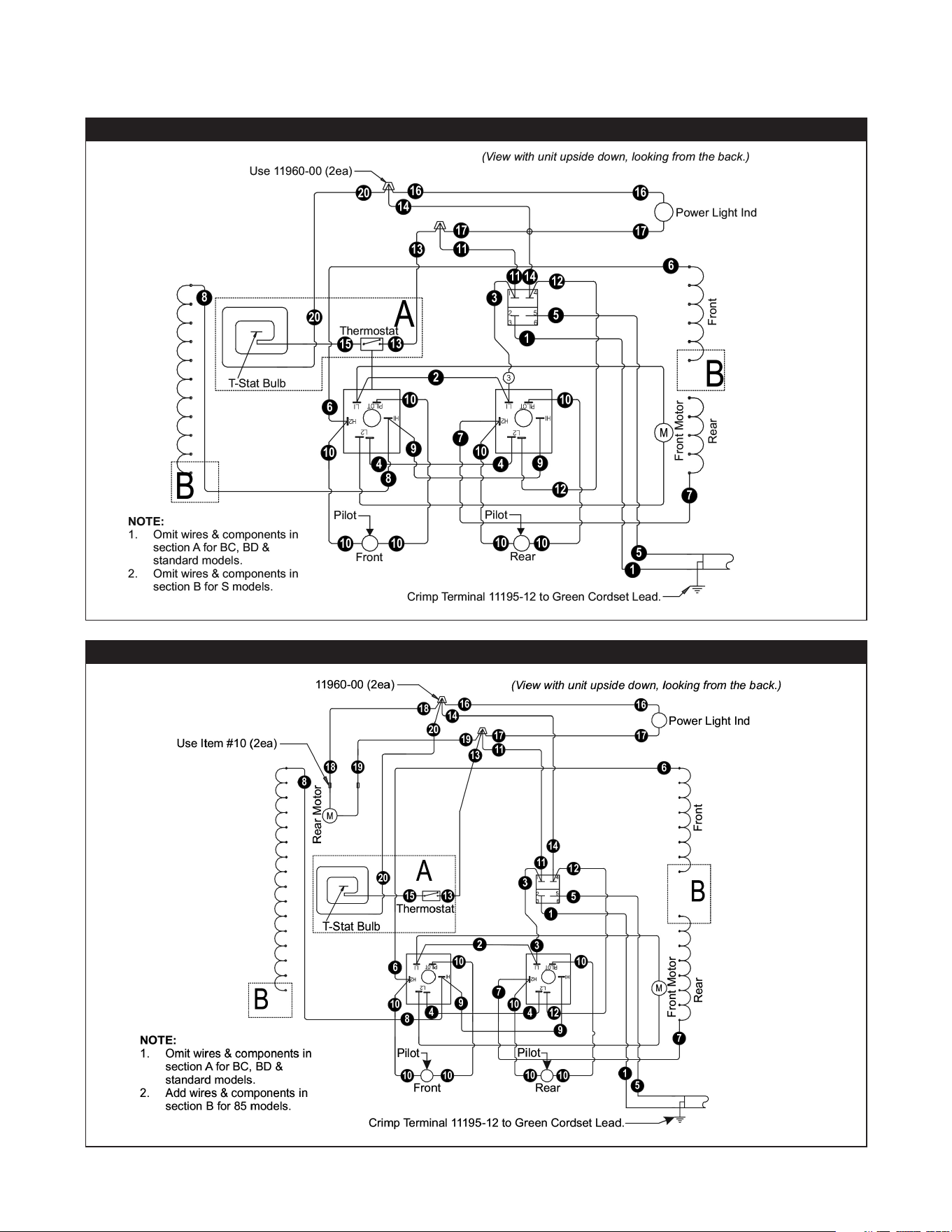
WIRING DIAGRAM – HR-31 & 50 (ALL)
WIRING DIAGRAM – HR-45, 75 & 85 (ALL)
WIRING DIAGRAMS

18
IMPORTANT FOR FUTURE REFERENCE
Please complete this information and retain this manual for the life of the equipment.
For Warranty Service and/or Parts, this information is required.
Model Number Serial Number Date Purchased
Notes

19
LIMITED EQUIPMENT WARRANTY
APW warrants to the original purchaser of new APW's products to be
free from defects in material or workmanship, under normal and proper
use and maintenance service as specified by APW and upon proper
installation and start-up in accordance with the instructions
supplied with each APW unit. APWs’ obligation under this warranty is
limited to a period of one [1] year from the date of original installation, or
eighteen [18] months from original invoice date, whichever occurs first.
Defects that occur as a result of normal use, within the time period and
limitations defined in this warranty, will at APWs’ discretion have the parts
replaced or repaired by APW or a APWs-authorized service agency.
THIS WARRANTY IS SUBJECT TO ALL LISTED CONDITIONS
Repairs performed under this warranty are to be performed by an
APW authorized service agency. APW will not be responsible for
charges incurred or service performed by non-authorized repair
agencies. In all cases, the nearest APW-authorized service agency must be
used. APW will be responsible for normal labor charges incurred in
the repair or replacement of a warrantied product within 50 miles
(80.5 km) of an authorized service agency. Time and expense charges
for anything beyond that distance will be the responsibility of the owner.
All labor will need to be performed during regular service hours. Any
overtime premium will be charged to the owner. For all shipments
outside the U.S.A. and Canada, please see the International Warranty
for specific details. It is t
he responsibility of the owner to inspect
and report any shipping damage claims, hidden or otherwise, promptly
following delivery. No mileage or travel charges will be honored on any
equipment that is deemed portable. In general, equipment with a cord
and plug weighing less than 50 lb. (22.7 kg) is considered portable and
should be taken or shipped to the closest authorized service agency,
transportation prepaid.
CONTACT
Should you require any assistance regarding the operation or maintenance
of any APW Manufacturing; phone or email our service department. In all
correspondence provide the model number and serial number of the unit
needing service; include the voltage or gas type.
Normal Business Hours: 8:00 a.m. to 4:30 p.m. Central
Telephone: 800-264-7827 Tech Service Option 2
Email: [email protected]
www.apwwyott.com
WARRANTY EXCLUSIONS
THE FOLLOWING WILL NOT BE COVERED UNDER WARRANTY.
APWs’ sole obligation under this warranty is limited to either repair
or replacement parts, subject to the additional limitations
detailed below. This warranty neither assumes nor authorizes any
person to assume obligations other than those expressly
covered by this warranty.
• Any product which has not been used, maintained, or installed in
accordance with the directions published in the appropriate
installation sheet and/or owner’s manual, including incorrect gas or
electrical connection. APW is not liable for any unit which has been
mishandled, abused, misapplied, subjected to harsh chemicals,
modified by unauthorized personnel, damaged by flood, fire, or other
acts of nature [or God], or which have an altered or missing serial
number.
• Installation, labor, and job checkouts, ca
libration of heat controls,
air and gas burner/bypass/pilot adjustments, gas or electrical system
checks, voltage and phase conversions, cleaning of equipment, or
seasoning of griddle surface.
• Replacement of fuses or resetting of circuit breakers, safety
controls, or reset buttons.
• Replacement of broken or damaged glass components, quartz
heating elements, and light bulbs.
• Labor charges for all removable and consumable parts in gas
charbroilers and hotplates, including but not limited to burners,
grates, and radiants.
• Any labor charges incurred by delays, waiting time, or operating
restrictions that hinder a service technician’s ability to perform
service.
• Replacement of parts that fail or are damaged due to normal wear
or labor for replacement of parts that can be replaced during a daily
cleaning routine, such as but not limited to silicone belts, PTFE non-
stick sheets, control labels, knobs, bulbs, fuses, quartz heating
elements, baskets, racks, and grease drawers.
• Any economic loss of business or profits.
• Non-OEM parts. Use of non-OEM parts without APWs’ approval
will void the warranty.
• Units exceeding one [1] year from original installation date, or more
than eighteen [18] months from original invoice date, whichever
comes first.
ADDITIONAL WARRANTIES
• Specific/chain-specific equipment may have additional and/or
extended warranties.
The foregoing warranty is in lieu of any and all other warran�es
expressed or implied and cons�tutes the en�re warranty.