Owner’s Manual Save this manual for future reference.
Williams Furnace Co. 250 West Laurel Street Colton, California 92324 U.S.A.
Do not store or use gasoline or other flammable
vapors and liquids in the vicinity of this or any other
appliance.
WHAT TO DO IF YOU SMELL GAS:
• Open all windows.
• Do not try to light any appliance.
• Do not touch any electrical switch; do not
use any phone or cell phone in your building.
• Extinguish any open flame.
• Immediately call your gas supplier from a
neighbor’s phone. Follow the gas supplier’s
instructions.
• If you cannot reach the gas supplier, call the fire
department.
Installation and service must be performed by a
qualified installer, service agency or the gas
supplier.
WARNING: Improper installation, adjustment, alteration,
service or maintenance can cause injury or property
damage. Refer to this manual. For assistance or for
additional information consult a qualified installer,
service agency or the gas supplier.
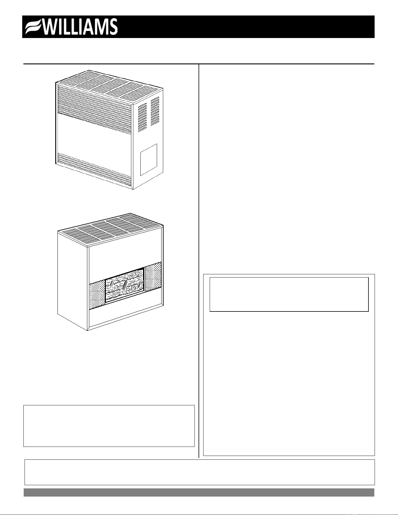
Vented Room Heaters
Model Numbers:
2001622A; 2011622A; 2031622A; 2051622A; 3501522A; 3511522A;
3531522A; 3551522A; 3501922A; 3511922A; 3531922A; 3551922A;
3502522A; 3511522A; 3532522A; 3552522A; 3502922A; 3512922A;
3532922A; 3552922A; 5001522A; 5011522A; 5031522A; 5051522A;
5001922A; 5011922A; 5031922A; 5051922A; 5002522A; 5012522A;
5032522A; 5052522A; 5002922A; 5012922A; 5032922A; 5052922A;
6501522A; 6511522A; 6531522A; 6551522A; 6501922A; 6511922A;
6531922A; 6551922A; 6502522A; 6512522A; 6532522A; 6552522A;
6502922A; 6512922A; 6532922A; 6552922A
FOR USE WITH NATURAL GAS ONLY
Model Numbers:
2001621A; 2011621A; 2031621A; 2051621A; 3501521A; 3511521A;
3531521A; 3551521A; 3501921A; 3511921A; 3531921A; 3551921A;
3502521A; 3512521A; 3532521A; 3552521A; 3502921A; 3512921A;
3532921A; 3552921A; 5001521A; 5011521A; 5031521A; 5051521A;
5001921A; 5011921A; 5031921A; 5051921A; 5002521A; 5012521A;
5032521A; 5052521A; 5002921A; 5011921A; 5032921A; 5052921A;
6501521A; 6511521A; 6531521A; 6551521A; 6501921A; 6511921A;
6531921A; 6551921A; 6502521A; 6512521A; 6532521A; 6552521A;
6502921A; 6512921A; 6532921A; 6552921A
FOR USE WITH LIQUEFIED PETROLEUM (L.P.) GAS ONLY
READ THIS OWNER’S MANUAL CAREFULLY BEFORE YOU INSTALL
YOUR NEW WILLIAMS HEATER.
WARNING: If the information in these instructions
is not followed exactly, a fire or explosion may
result causing property damage, personal injury or
loss of life.
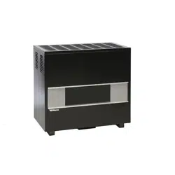
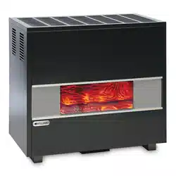
ENCLOSED MODEL
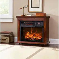
FIREPLACE MODEL
WARNING:
Installation and repair must be done by a qualified service person. The appliance should be inspected
before use and at least annually by a professional service person.

Warranty
2
Warranty & Installation Record – 2
The manufacturer, Williams Furnace Co., warrants this wall furnace or heater to the original purchaser under the following conditions:
LIMITED ONE-YEAR WARRANTY
1. Any part thereof which proves to be defective in material or workmanship within one year from date of original purchase for use will be replaced at the Manufacturer’s
option, FOB to its factory.
2. No liability is assumed by the Manufacturer for removal or installation labor costs, nor for freight or delivery charges.
LIMITED EXTENDED WARRANTY
1. In addition to the above limited one-year warranty on the complete unit, any combustion chamber which burns out or rusts under normal installation, use and service
conditions during a period of nine years following expiration of the one-year warranty period will be exchanged for a like or functionally similar part.
2. No liability is assumed by the Manufacturer for removal or installation labor costs, nor for freight or delivery charges.
LIMITATIONS
1. THIS LIMITED WARRANTY IS THE ONLY WARRANTY MADE BY THE MANUFACTURER, IMPLIED WARRANTIES OF MERCHANTABILITY OR FITNESS FOR ANY
PARTICULAR PURPOSE ARE LIMITED TO THE SAME ONE YEAR TERM AS THE EXPRESS WARRANTY. UNDER NO CIRCUMSTANCES SHALL THE
MANUFACTURER BE LIABLE FOR INCIDENTAL, CONSEQUENTIAL, SPECIAL OR CONTINGENT DAMAGES OR EXPENSES ARISING DIRECTLY OR INDIRECTLY
FROM ANY DEFECT IN THE PRODUCT OR ANY COMPONENT OR FROM THE USE THEREOF. THE REMEDIES SET FORTH HEREIN ARE THE EXCLUSIVE
REMEDIES AVAILABLE TO THE USER AND ARE IN LIEU OF ALL OTHER REMEDIES.
Some states do not allow limitation on how long an implied warranty lasts, and some states do not allow the exclusion or limitation of incidental or consequential
damages, so the above limitations or exclusions may not apply to you.
2. This warranty does not include any charge for labor or installation.
3. This warranty does not extend to painted surfaces or to damage or defects resulting from accident, alteration, misuses or abuse or improper installation.
4. This warranty does not cover claims which do not involve defective workmanship or materials.
DUTIES OF THE CONSUMER
1. The heating equipment must be installed by a qualified installer and operated in accordance with the installation and homeowner’s instructions furnished with the
equipment.
2. Any travel, diagnostic costs, service labor, and labor to repair the defective unit will be the responsibility of the owner.
3. A bill of sale, cancelled check, payment record or permit should be kept to verify purchase date to establish the warranty period.
4. Have the installer enter the requested information in the space below.
GENERAL
1. The manufacturer neither assumes nor authorizes any person to assume for it any other obligation or liability in connection with said equipment.
2. Service under this warranty should be obtained by contacting your dealer. Provide the dealer with the model number, serial number, and purchase date verification.
3. If, within a reasonable time after contacting your dealer, satisfactory service has not been received, contact: Customer Service Department, 250 West Laurel Street,
Colton, CA 92324 for assistance.
4. THIS WARRANTY GIVES YOU SPECIFIC LEGAL RIGHTS AND YOU MAY ALSO HAVE OTHER RIGHTS WHICH VARY FROM STATE TO STATE.
Installation Record
Model No. ______________________________________________________________ Serial No. ___________________________
Original Purchaser ____________________________________________________________________________________________
Address ____________________________________________________________________________________________________
City and State ___________________________________________________________ Zip ________________________________
Dealer _____________________________________________________________________________________________________
Address ____________________________________________________________________________________________________
City and State ___________________________________________________________ Zip ________________________________
Installation Date _______________ Name ________________________________ Signature_________________________________
(Dealer or authorized representative who certifies that this appliance is installed in accordance with Manufacturer’s instructions and local codes.)

Contents
Your Williams Warranty ................................................................. 2
Installation Record ......................................................................... 2
Table of Contents .......................................................................... 3
Safety Rules .................................................................................. 4
Introduction .................................................................................... 5
Basic Description ........................................................................... 5
Basic Tools Needed ...................................................................... 5
Basic Materials Needed................................................................. 5
Optional Accessories ..................................................................... 5
Unpack Your Heater ...................................................................... 5
Installing Your Heater .............................................................. 6-15
Locating the Heater.......................................................... 6-8
Combustion & Ventilation Air ......................................... 8-11
Thermostat Installation ................................................. 11-12
Vent Installation ........................................................... 13-15
Operating Your Heater .......................................................... 16-18
Start Up Procedure ...................................................... 16-17
Gas Conversion Kits ........................................................... 17
Operating Instructions ........................................................ 18
How To Care For Your Heater ............................................... 19-20
Repair Parts & Parts Lists ..................................................... 21-26
Blower Accessory 2102 ......................................................... 27-28
Troubleshooting Chart ........................................................... 29-31
SERVICE HINTS .......................................................... Back Cover
How To Order Repair Parts .......................................... Back Cover
Quick Reference: Here’s how to…
Unpack the heater......................................................................... 5
Learn how to unpack the new Williams Heater and verify that all
its parts are in working order.
Install the heater ...................................................................... 6-15
Thermostat and Vent Installation is all explained starting on page
8 thru 11.
Operate the heater ................................................................. 16-18
Igniting the heater for the first time.
Caring for Your Heater ........................................................... 19-20
Learn how to keep your new Williams Heater operating.

Safety Rules
4
WARNING: Read these rules and the instructions
carefully. Failure to follow these rules and
instructions could cause a malfunction of the
heater. This could result in death, serious bodily
injury and/or property damage.
INSTALLATION MUST CONFORM TO LOCAL CODES. IN THE
ABSENCE OF LOCAL CODES, INSTALLATION MUST
CONFORM TO THE NATIONAL FUEL GAS CODE, ANSI Z223.1.
THE APPLIANCE, WHEN INSTALLED MUST BE
ELECTRICALLY CONNECTED AND GROUNDED IN
ACCORDANCE WITH LOCAL CODES OR, IN THE ABSENCE
OF LOCAL CODES, WITH THE CURRENT NATIONAL
ELECTRICAL CODE ANSI/NFPA NO. 70.
In Canada:
1. Installation must conform to local codes or, in
the absence of local codes, the current
CAN/CGA B149 installation code.
2. The appliance, when installed, must be
electrically connected and grounded in
accordance with local codes or, in the absence
of local codes, with the current CSA C22.1
Canadian Electrical code.
3. Field conversions for high altitude are not
permitted in Canada.
4. Reference is made in this manual regarding gas
type as L.P.G. Be advised that L.P.G. is not
available in Canada, refer to propane/L.P. Gas.
1. Use only manufacturer's replacement parts. Use of any
other parts could cause injury or death.
2. DO NOT install the heater in an alcove.
3. DO NOT install this heater where it could be isolated by
closing doors to the heated space.
4. DO NOT install this heater in a travel trailer or
recreational vehicle.
5. MAINTAIN all clearances specified in section "Locating
Wall heater and Thermostat" and "Vent Installation."
6. BE SURE this heater is for the type of gas to be used.
Check the rating plate by the gas valve in the lower
cabinet. Do not change it to use other gases without the
proper manufacturer’s Gas Conversion Kit.
7. For natural gas, the minimum inlet gas supply pressure
for the purpose of input adjustment is 5" water column.
The maximum inlet gas supply pressure is 7" water
column.
For L.P. Gas, the minimum inlet gas supply pressure for
the purpose of input adjustment is 11" water column. The
maximum inlet gas supply pressure is 13" water column.
8. Any safety screen, guard or parts removed for servicing
this appliance must be replaced prior to operating the
appliance to avoid property damage, bodily injury or
death.
9. Install the heater vent directly to the outdoors, so that
harmful gases will not collect inside the building. Follow
the venting instructions for your type of installation
exactly. Use only the type and size of vent pipe and
fittings specified.
10. BE SURE to provide for adequate combustion and
ventilation air. The flow of this air to the heater must not
be blocked.
11. NEVER vent flue gases into another room, a fireplace or
any space inside a building. This could cause property
damage, bodily injury or death.
12. Never test for gas teaks with an open flame. Use a soap
solution to check all gas connections. This will avoid the
possibility of fire or explosion.
13. ALLOW the heater to cool before servicing. Always shut
off electricity and gas to the heater when working on it.
This will prevent any electrical shocks or burns.
14. DUE TO HIGH TEMPERATURES, locate the heater out
of traffic and away from furniture and draperies.
15. ALERT children and adults to the hazards of high surface
temperatures and warn them to keep away to avoid
burns or clothing ignition.
16. CAREFULLY supervise young children when they are in
the same room with the heater.
17. DO NOT place clothing or other flammable material on or
near heater.
18. INSTALLATION and REPAIR must be done by a
qualified service person. The appliance should be
inspected before use and at least annually by a
professional service person. More frequent cleaning may
be required due to excessive lint from carpeting, bedding
material, etc. It is important that control compartments,
burners and circulating air passages be kept clean.
Failure to keep burner-control compartment and other
parts of heater clean can cause dangerous conditions to
develop which can cause injury and even death.
19. BEFORE INSTALLING the optional blower: To avoid
electrical shock, turn off electrical circuits that pass
through the wall where you are going to install the
heater.
20. BE AWARE of good safety practices by wearing personal
protective equipment such as gloves and safety glasses
to avoid being injured by sharp metal edges in or around
heater and while cutting or drilling holes in wood and/or
sheet metal.
21. CAUTION: Label all wires prior to disconnection when
servicing controls. Wiring errors can cause improper and
dangerous operation. Verify proper operation after
servicing.
22. DO NOT store or use gasoline or other flammable liquids
or vapors near the heater.
WARNING: Do not use this heater if any part
has been under water. Immediately call a
certified service technician to inspect the heater
and to replace any part of the control system and
any gas control which has been under water.

Introduction
Introduction – 5
Please read our instructions before you install and use your heater. This will help you obtain the full value from this heater. If the
answer to the problem is found within this instruction manual, it could help you avoid needless service costs.
Basic Description
Always consult your local heating or plumbing inspector,
building department or gas company regarding regulations,
codes or ordinances which apply to the installation of a vented
room heater.
No electrical power is required unless furnace is equipped with
an optional blower accessory.
The efficiency rating of this appliance is a product thermal
efficiency rating determined under continuous operating
conditions and was determined independently of any
installation system.
Warmed air is discharged into the room in which the heater is
located. The heater contains a single multi-slot gas burner.
Combustion air is drawn in from the room where the heater is
located and is vented out of the heater vertically through vent
piping to a roof vent top. (Vent equipment is not supplied with
the heater).
The combustion chamber is built of heavy-gauge steel. The
heater cabinet is also constructed of heavy-gauge steel and has a
powder-coat paint finish.
The heater controls are located behind an access door on the side
of the heater. All models are equipped with CSA/AGA listed gas
valves and pilots.
The appliance is equipped with a vent safety shutoff system,
designed to protect against improper venting. Operation of this
room heater when not connected to a properly installed and
maintained venting system or tampering with the vent safety
shutoff system can result in carbon monoxide (CO) poisoning and
possible death.
This heater is design certified in accordance with American
National Standard & CSA Standard Z21.86 and CSA 2.32 as a
vented room heater and must be installed according to these
instructions.
Basic Tools Needed
Hand drill or properly grounded electric drill
1/8 inch and 3/16 inch drill bit (metal)
6 foot folding ruler or tape measure
Screwdriver (Phillips Head)
Pliers (Wire Cutting)
Hammer
Stud locator or small finishing nails
8 inch adjustable wrench
Keyhole saw or saber saw
2-10 inch or 12 inch pipe wrenches
Gloves and safety glasses
Basic Materials Needed
Pipe joint compound resistant to L.P. gases.
Electrical wiring supplied as needed for optional blower.
Pipe and fittings to make connections to the heater.
Helpful Installation Information
The following booklets will help you in making the installation:
ANSI/NFPA 70-1990 or current edition "National Electrical Code". In Canada: CSA C22.1 Canadian Electrical Code.
American National Standard NFPA54/ANSI Z223.1 1988 or current edition "National Fuel Gas Code".
Obtained from: American National Standards Institute, Inc., 1430 Broadway, New York, N Y 10018.
In Canada: CAN/CGA B149.
Optional Accessories
Blower
To increase circulation of warmed air within the heated space, you
may use Blower Accessory Kit 2102, on all models except
2001622A and 2001621A.
Floor Board Model 4163 or 4167
Available in black to match the heater.
Vent Collar Model 9102, 9104 or 9106
Available in black to match the heater.
Unpack Your Heater
Examine all packing material carefully. Look for loose parts
before discarding. Store all parts where they cannot be lost or
damaged before you need them.
NOTE: Check the burner rating plate, located in the burner
compartment, to make sure your heater is equipped to operate on
the type of gas available (either natural or L.P. Gas). DO NOT
convert unit from natural gas to L.P. Gas or from L.P. Gas to
natural gas without the proper manufacturer’s gas conversion kit.
Installing Your Heater
6
The following steps are needed for proper installation and safe
operation of your heater. If you have any doubts as to any
requirements, check with local authorities for local and state
codes affecting the installation.
Obtain professional help where needed.
DO NOT install this heater in a travel trailer, recreational vehicle,
or mobile home.
IMPORTANT
For satisfactory and trouble-free operation, be sure to:
1. Locate the heater properly within the space to be heated.
2. Provide for adequate combustion air, adequate air circulation
around the cabinet inside the open room and a proper vent
system.
3. Maintain all minimum clearances which apply to your heater.
Locating the Heater
WARNING: Gas burning appliances require air for
combustion and proper venting. Minimum fresh air
opening of 1 square inch per 1,000 Btu/hr. input
rating must be provided for ventilation.
EXAMPLE: A 30,000 Btu/hr. input unit requires the equivalent of a
30 inch wide window be open 1 inch for safe operation.
WARNING: Danger of property damage, bodily
injury or death. Even when a house meets
requirements for unconfined space with adequate
air infiltration, it is recommended that a fresh air
intake be installed to lessen the possible dangers
from any future changes on the home.
Consider the following points before attempting to install the
heater:
1. In choosing the location for the heater, the following factors
should be considered:
a. Convenience to the gas supply.
b. Arrangement of the rooms or area to be heated.
c. Probable location of the furniture.
d. General appearance.
e. Safe clearance from anything that could catch fire.
f. Ability to properly vent the heater.
2. Locate the heater centrally in the area which it is to heat. The
ideal location is at the source of cold air, which is an outside
wall. If the heater is on an outside wall, the cold air will be
warmed before it moves through the room.
3. Place the heater where the air will circulate freely throughout
the area to be heated. If one heater is intended to heat the
entire house, it is advisable to consider the installation of
grilles immediately below the ceilings to permit circulation of
hot air from room to room. Return air grilles are also
desirable.
4. Be certain the heater is placed where the air is free to
circulate around it. Never install the heater in a wall recess.
The minimum clearance required to any wall or object can be
found on the rating plate located inside the heater control
door on the base plate. We recommend a 24-inch min.
clearance from the burner access door for the ease of lighting
and for observation of pilot and burner flames.
5. The heater must be installed so that the draft hood is in the
same pressure zone as the combustion air.
6. The heater may be placed directly on wood floors. Heavy
pile or shag rugs may restrict normal air flow. Some floor
coverings discolor easily from even low heat. To assure safe
operation, a metal or wood panel, extending the full depth
and width of the appliance must be placed under the heater.
Optional floor boards are available from Williams.
7. Do not place the heater where curtains, draperies, or any
other material may come into contact with any part of the
heater.
GAS CONTROLS
1. All models are regulated on natural or L . P. Gases. The
regulator is built into the gas control valve.
2. All models are equipped with a 100% pilot safety shutoff and
vent safety shutoff system.
3. CAUTION: Do not connect 115V electrical service line to gas
control valve or wall thermostat.
GAS SUPPLY
For natural gas, the minimum inlet gas supply pressure for the
purpose of input adjustment is 5" water column. The Maximum
inlet gas supply pressure is 7" water column.
For L.P. Gas, the minimum inlet gas supply pressure for the
purpose of input adjustment is 11" water column. The maximum
inlet gas supply pressure is 13" water column.
The gas pressure and input to the burners must not exceed the
rated input and pressure shown on the rating plate. On Natural
Gas, the manifold pressure should be 4 inches water column. The
manifold pressure should be 10 inches water column for L.P. Gas.
Orifice changes may be required to suit the gas supplied.
For heaters located at elevations between sea level and 2,000
feet, the measured input must not be greater than the input shown
on the rating plate of the heater. For elevations above 2,000 feet,
the measured input must not exceed the input of the rating plate
reduced by 4 percent for each 1,000 feet that the heater is above
sea level.
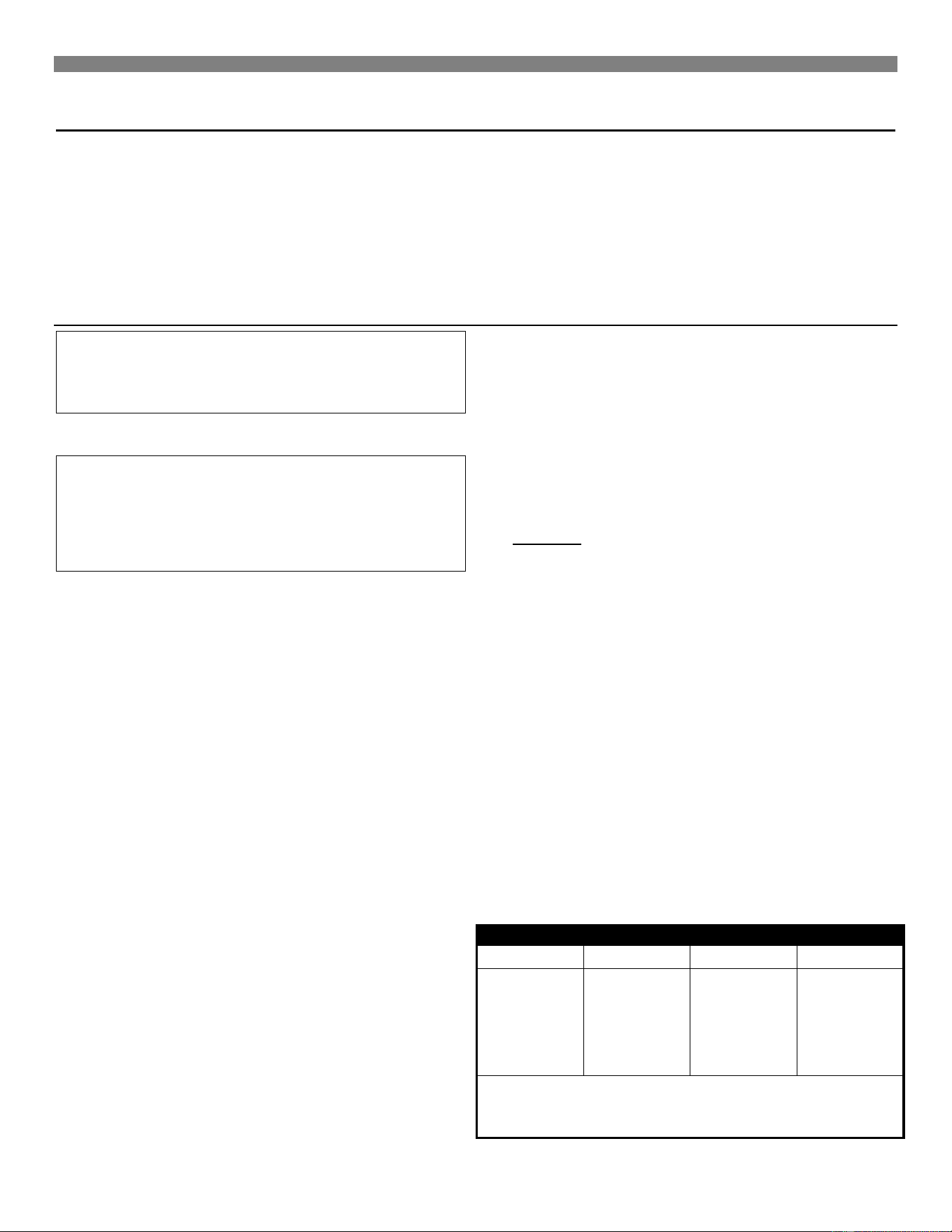
MINIMUM REQUIRED CLEARANCES
MODEL
"A" SIDE
"B" CEILING
"C" REAR
200 SERIES
350 SERIES
500 SERIES
650 SERIES
2"
6"
6"
6"
36"
57"
57"
57"
3"
6"
6"
6"
24” min. Clearance is recommended on side with burner access
door for ease of lighting and for observation of pilot and burner
flames.
Installing Your Heater
Note: Minimum fresh air opening is 1 square inch per 1,000
Btu/hr.
GAS PIPING
State and local authorities have established codes regulating the
installation of gas burning equipment. Consult your gas supplier or
gas company for complete information. In the absence of local
codes, all aspects of the installation must comply with the National
Fuel Gas Code ANSI Z223.1. In Canada: Follow the CAN/CGA-
B149.1(2) Canadian Standard.
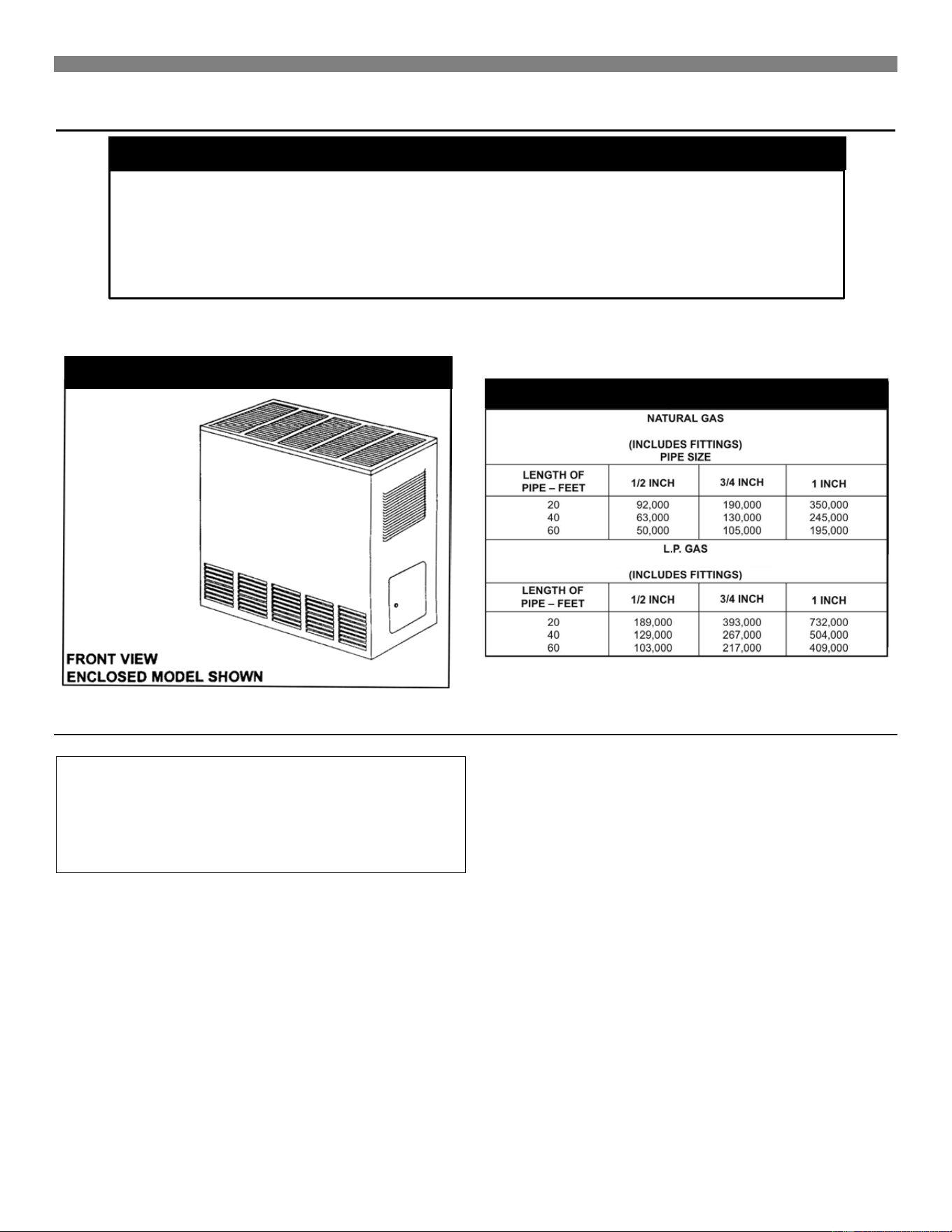
1. Use ½-inch pipe or semi-rigid tubing for natural and Liquefied
Petroleum Gases. DO NOT USE FLEXIBLE HOSE.
Appliance connectors of corrugated metal tubing and fittings
that are listed by a nationally recognized testing agency may
be used if accepted by the local code authorities. FOLLOW
THE MANUFACTURER’S INSTALLATION INSTRUCTIONS.
This type of connection may only be installed in the room
where the heater is located.
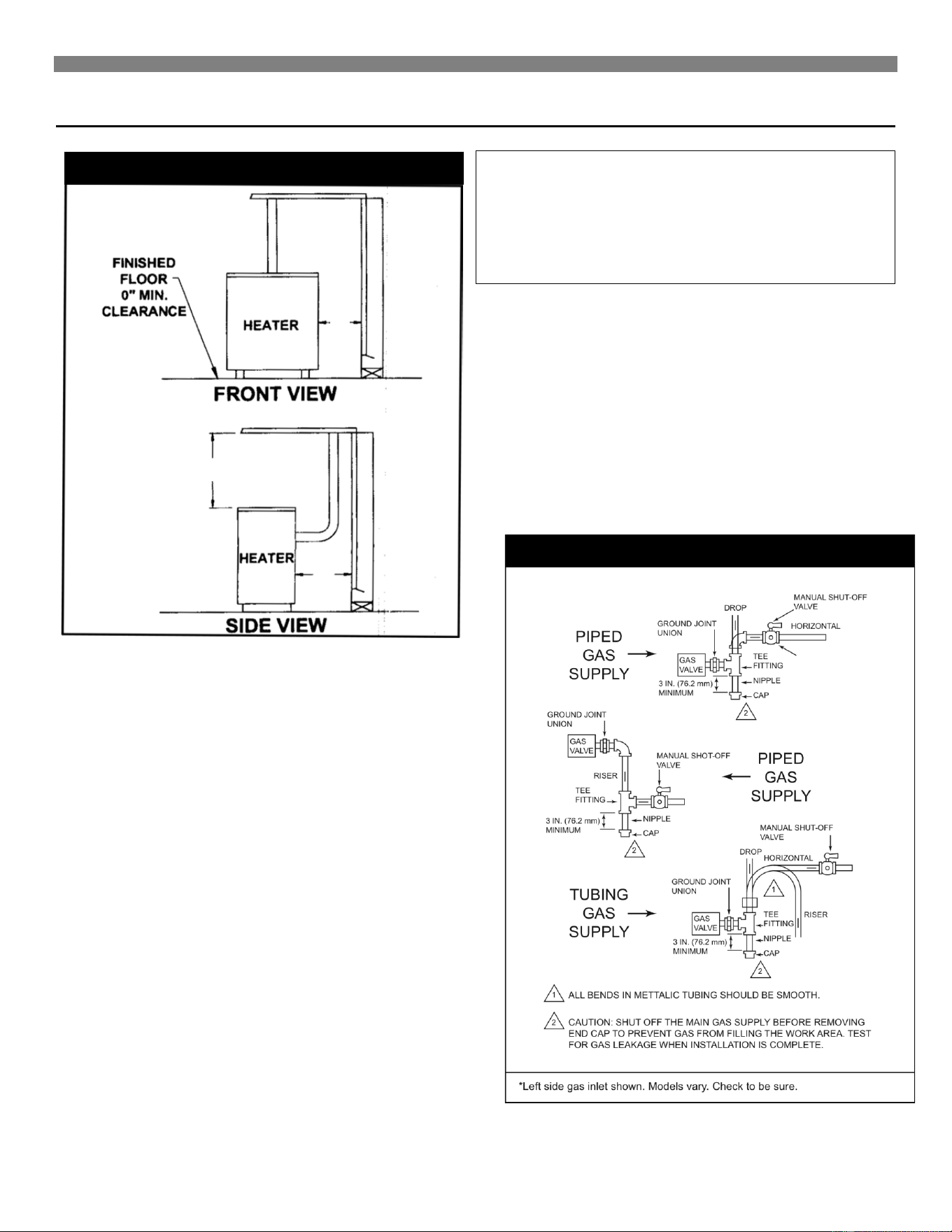
2. A manual shutoff valve and union must be installed in the gas
supply line just ahead of the connection to the heater. The
manual valve must include a 1/8-inch NPT plugged tapping
accessible for connection of a test gauge.
3. Unions in the gas supply lines should be of the ground joint
type. Compounds used on threaded pipe joints must be
resistant to the action of liquefied petroleum gases.
WARNING: When connecting field piping, use a
second wrench to keep the heater valve from
turning. Support field piping properly, stress and
over tightening could damage the gas valve and
result in dangerous gas leaks which can cause
dangerous conditions including property damage,
bodily injury, and even death.
4. A drip leg (Figure 2) should be installed to constitute a trap to
catch any condensate that may be in the gas. The drip leg
should be readily accessible for cleaning.
5. The heater must be disconnected from the gas supply system
and from the heaters individual shutoff valve when the system
is tested at a pressure in excess of 1/2 PSI.
6. Check all factory and field pipe joints for gas leaks before and
after lighting the heater. Use a soap solution. Never use a
match or open flame. Correct any leak (s), no matter how
small.
7. Piping supply shall be supported to prevent sagging damage
to the controls and hazardous gas leaks. To prevent freezing
where the supply pipe is exposed to cold air, wrap the pipe or
run it underground.
FIGURE 1 Minimum Required Clearances
FIGURE 2 Left Side Gas Inlet
A
B
C
OPEN IN FRONT TO
PROVIDE SERVICE,
ACCESS AND
CLEARANCE TO
COMBUSTIBLES.
OPEN IN FRONT TO
PROVIDE SERVICE,
ACCESS AND
CLEARANCE TO
COMBUSTIBLES.
1/8 IN NPT PLUGGED
HOLE FOR TEST
GUAGE
Installing Your Heater
8
IMPORTANT: All piping must comply with local codes and ordinances or with the National Fuel Gas Code (ANSI Z223.1 NFPA No. 54),
whichever applies. (In Canada: CAN/CGA B149).
Combustion & Ventilation Air
WARNING: Danger of property damage, bodily
injury or loss of life. The furnace and any other fuel-
burning appliances must be provided with enough
fresh air for proper combustion and ventilation of
flue gases. Most homes will require that outside air
be supplied into the heated area.
The high cost of energy for home heating has brought about new
materials and methods used to construct or remodel most current
homes. The improved construction and additional insulation has
reduced the heat loss and made these homes much tighter
around windows and doors so that infiltrated air is minimal. This
creates a problem to supply combustion and ventilation air for
gas-fired or other fuel burning appliances. Any use of appliances
that pull air out of the house (clothes dryers, exhaust fans,
fireplaces, etc.) increases this problem and appliances could be
starving for air.
In addition, these energy measures mean that your home will
retain more water vapor or a higher relative humidity.
High humidity, especially during cold weather, may be damaging
to buildings because condensation forms on windows and inside
walls.
The combination of a tight energy efficient home with the use of
exhaust fans, fireplaces, clothes dryers, and gas appliances result
in more and more air being drawn from the house until fresh air
may be sucked back into the house down a furnace flue or
fireplace chimney. Carbon monoxide can be the result. Carbon
monoxide (CO) is a colorless, odorless gas produced when fuel is
not burned completely or when the flame does not receive
sufficient oxygen. Automobiles, charcoal, wood fires and
improperly vented or air-starved coal, oil and gas furnaces or
other appliances can produce carbon monoxide.
Be aware of these air-starvation signals:
1. Headaches, nausea, dizziness.
2. Excessive humidity shown by heavily frosted windows or a
moist "clammy" sensation.
3. Fireplace smoke fills the room or will not draw.
4. Furnace flue backs up.
FIGURE 3 Proper Piping Practice
FIGURE 4 Enclosed Model
FIGURE 5 Gas Pipe Sizes
PIPE CAPACITY - Btu/hr.
PIPE CAPACITY - Btu/hr.

Installing Your Heater
AIR REQUIREMENTS
The requirements for providing air for combustion and ventilation
are listed in the National Fuel Gas Code NFPA 54/ANSI Z223.1 (in
Canada: CAN/CGA B149). Most homes will require that outside
air be supplied to the heated area by means of ventilation grilles
or ducts connecting directly to the outside or spaces open to the
outdoors such as attic or crawl space. The only exception is when
the furnace area meets the requirements and definitions for an
unconfined space with adequate air infiltration.
WARNING: Danger of property damage, bodily
injury or loss of life. The furnace and any other fuel-
burning appliances must be provided with enough
fresh air for proper combustion and ventilation of
flue gases. Most homes will require that outside air
be supplied into the heated area.
All air openings and connecting ducts must comply with the
following:
If the furnace is installed in an area with another gas appliance(s),
the total input rating of all appliances must be considered when
determining the free area requirements for combustion and
ventilation air openings.
Ducts must have the same cross-sectional area as the free area
of the openings to which they connect. The minimum dimension
of rectangular air ducts must not be less than 3-inches in length or
height.
LOUVERS / GRILLES AND SCREENS COVERING
FREE AREA OPENINGS
If a screen is used to cover the opening(s), it must not be smaller
than 1/4-inch mesh. Use the free area of a louver or grille to
determine the size opening required to provide the free area
specified. If the free area is not known, assume a 20% free area
for wood and a 60% free area for metal louvers or grilles.
EXAMPLE 1
FURNACE LOCATED IN UNCONFINED SPACE.
*
*
An unconfined space must have a volume of a minimum 50 cubic
feet per 1000 Btu/hr. of total of all appliances in area. Adjoining
rooms may be included only if there are no doors between the
rooms, or if special provisions are made such as ventilation grilles
installed between connecting rooms.
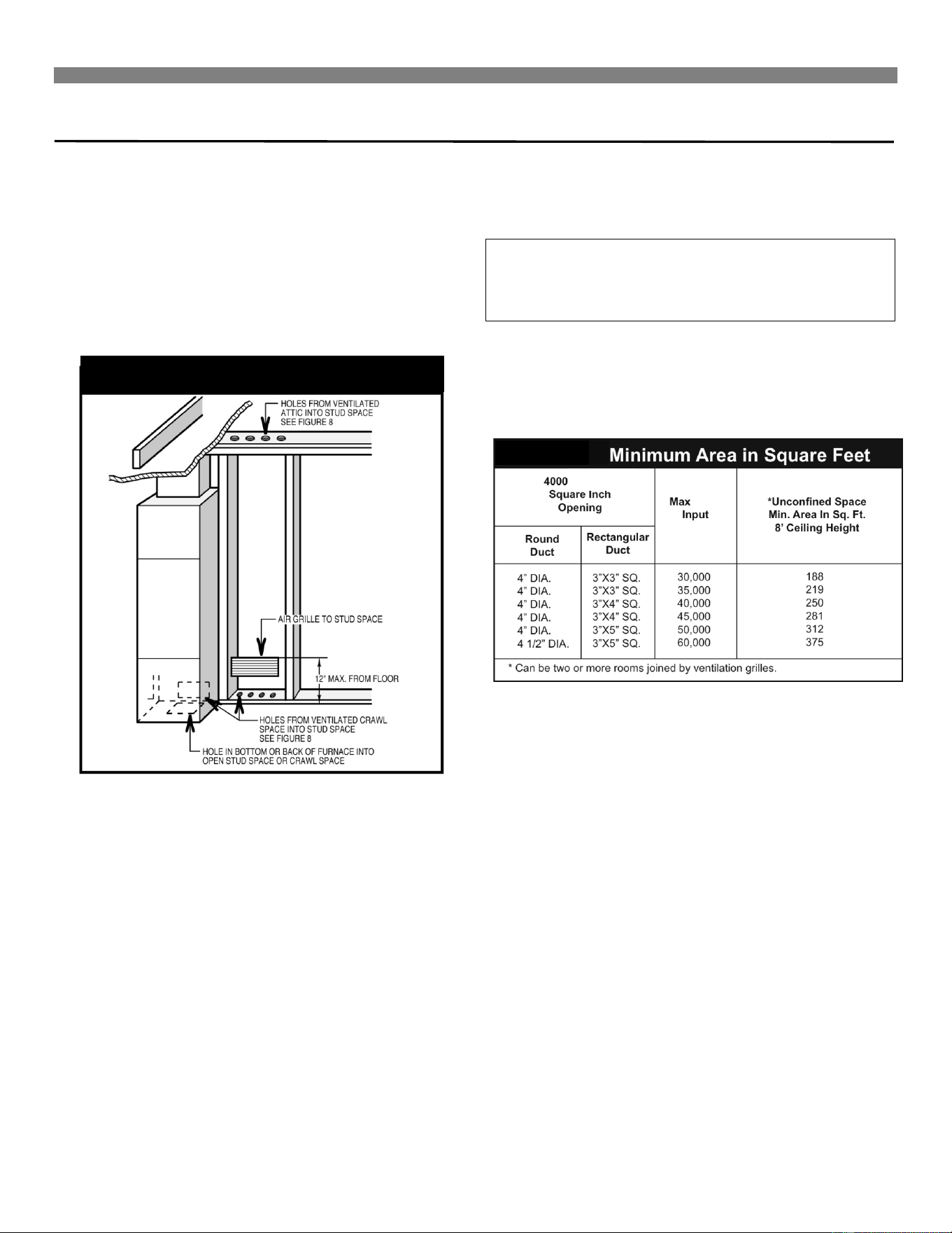
Page 10, figure 8 shows the minimum area in square feet' based
on 8 foot ceiling heights, required for different Btu/hr. input ratings.
A. If your furnace is in an open area (unconfined space*) the
air that leaks through the cracks around doors and windows
may be enough for combustion and ventilation air. The doors
should not fit tight. The cracks around windows should not
be caulked or weather stripped.
To determine if infiltration air is adequate, perform following
checks:
1. Close all doors and windows. If you have a fireplace,
start a fire and wait until flames are burning vigorously.
2. Turn on all exhausting devices, such as:
kitchen and bathroom exhaust fans
dryers (gas and electric)
3. Turn on all vented gas appliances, such as:
heating equipment (includes any room heaters)
water heater
4. Wait ten (10) minutes for drafts to stabilize.
5. Check for draft hood spillage at each appliance. (Hold a
lighted match 2 inches from draft opening. See Fig. 6.)
B. No Spillage
If the match flame pulls toward draft hood - this indicates
sufficient infiltration air:
1. Return exhausting devices and appliances to the
condition you found them.
C. Draft Hood Spills
If there is spillage at a draft hood (match goes out or flame
wavers away from draft hood):
1. Check for plugged flue connectors and chimneys. Check
and repair, stoppage and test again.
2. If you have a fireplace, open a window or door near the
fireplace and then check for spillage.
a) If spillage stops, do not use the fireplace without a
nearby window or door open until you can supply
fresh air by a permanent duct.
3. If you have kitchen and bathroom exhaust fans, turn
them off and check for spillage.
a) If spillage stops, do not use exhaust fans until you
can supply fresh air by a permanent duct.
WARNING: Danger of property damage, bodily
injury or loss of life. Draft hood spillage, with
unobstructed vents, indicates that additional air
must be brought into the structure from outside.
Keep a window open (minimum 2 inches) near the
appliance until a permanent air duct is installed.
FIGURE 6 Draft Hood Spillage
Installing Your Heater
10
4. Spillage means air starvation and a fresh air duct or air
intakes must be installed to provide air directly to the
furnace or other gas appliance.
D. If spillage exists or when the furnace is in a building of tight
construction where the windows and doors are weather-
stripped, air for combustion and ventilation must be obtained
from outdoors or space open to the outdoors.
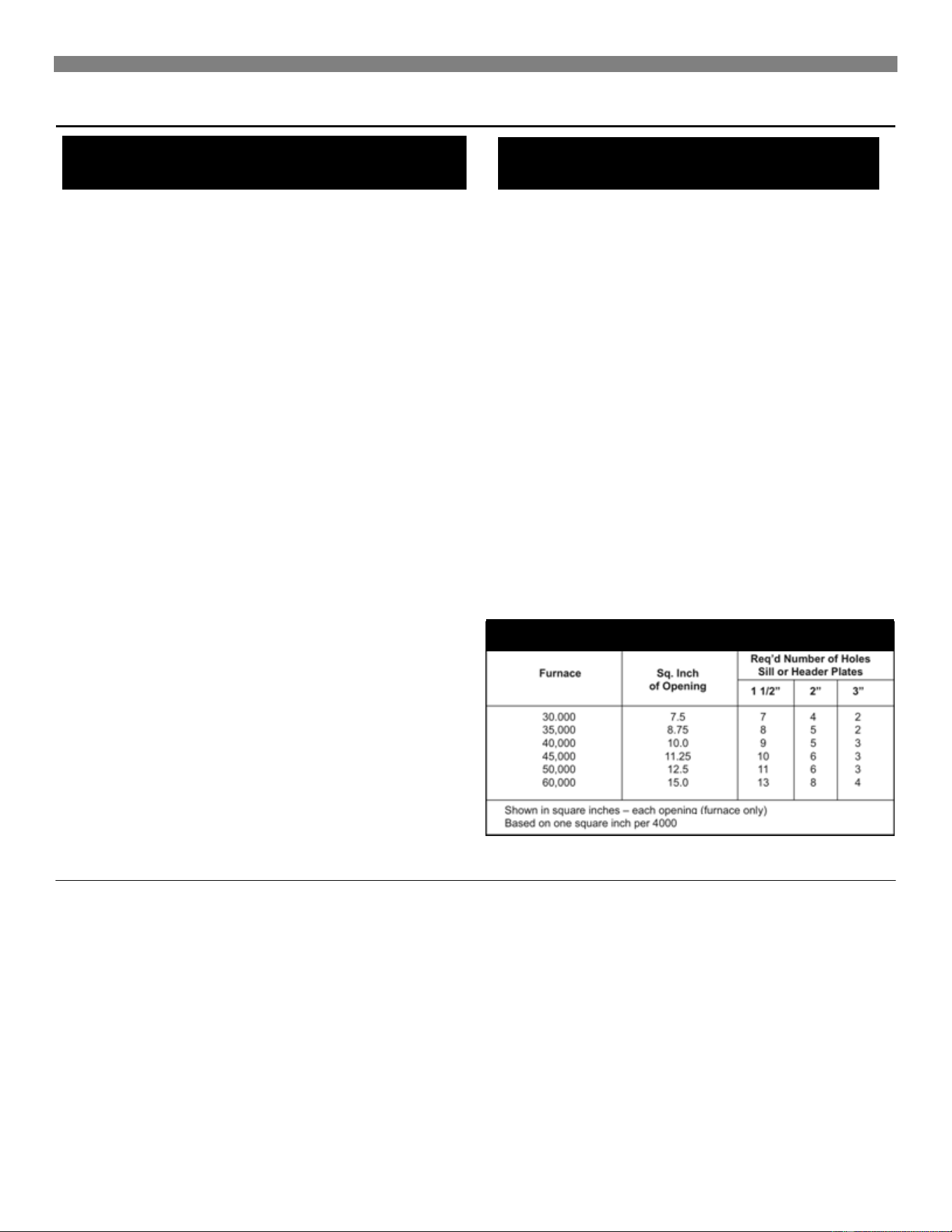
Provide an opening(s) having a total free area of 1-square inch
per 4000 Btu/hr. for the total of all appliances. The required area
is shown on page 11, Fig. 11.
Fig. 7 shows a typical duct going into ventilated crawl space
or attic.
1. Duct must terminate at a point not more than 1 foot
above the floor.
2. Duct size must be at least 1 inch of free area for each
4000 Btu/hr. of input of all appliances in area.
EXAMPLE 2.
FURNACE LOCATED IN CONFINED SPACE.
If furnace is installed in a confined space, it must be provided with
free air for proper combustion and ventilation of flue gases by one
of the following methods.
A. All Air From Inside Building:
If the confined space adjoins an unconfined, provide two
permanent openings, one within 12 inches of the top and one
within 12 inches of the bottom of the room connecting directly to
unconfined space. Each opening must have a free area of at least
100 square inches or 1 square inch per 1000 Btu/hr. combined
input of appliances in one room if combined input exceeds
100,000 Btu/hr.
WARNING: Danger of property damage, bodily
injury or loss of life. The adjoining unconfined
space must have adequate air infiltration as defined
in example 1.
FOR EXAMPLE: Your furnace is rated at 50,000 Btu/hr. The water
heater is rated at 30,000 Btu/hr. The total is 80,000 Btu/hr. Yo u
need two grilles, each with 100 square inches of free opening.
Metal grilles have about 60% free area, so you need two metal
grilles each with 160 square inches of louvered area.
Refer to figure as shown on Page 11, Fig. 9, which shows grille
installation. Using the previous example, the two connecting
rooms plus the closet must equal at least 500 sq. feet to handle
the combined input 50,000 plus 30,000.
B. All Air From Outdoors:
If confined space doesn't adjoin an unconfined space then air
must be provided from outdoors or spaces open to outdoors such
as attic or crawl space.
Provide two permanent openings, one within 12 inches of top, one
within 12 inches of bottom of room connecting directly, or by using
ducts, with the outdoors or areas open to outdoors.
If opening connects directly to, or within vertical ducts, the free
area of each opening must be at least 1 square inch per 4000
Btu/hr. combined input of appliances in area.
If horizontal ducts are used, the free area of each opening must
be at least 1 square inch per 2000 Btu/hr. combined input of
appliances in area.
FIGURE 7 Fresh Air duct
Btu/hr. Per
Btu/hr.
FIGURE 8
Installing Your Heater
FOR EXAMPLE: Your furnace is rated at 50000 Btu/hr. The water
heater is rated at 30,000 Btu/hr. The total is 80,000 Btu/hr. You
need two grilles, each with 20-square inches of free opening,
unless connected by horizontal ducts which would require each
grille or opening to have a free area of 40 square inches.
Openings for inlet or outlet air should not be made into attic area if
attic is equipped with a thermostat controlled power vent.
Thermostat Installation
Williams’ heaters are operated by a millivolt type thermostat.
Current to the thermostat is supplied by the pilot generator. Do not
connect to electricity. Anticipator settings are not required.
1. If an old thermostat is being replaced and is in a satisfactory
location and the wiring appears to be in good condition, use
existing wiring. If in doubt, use new wire.
2. If a new location is chosen or if this is a new installation,
thermostat cable must first be run to the location selected. All
wiring must agree with local codes and ordinances. These
instructions cover bringing the wire down from the attic but it
can be run from a basement or crawl space using similar
methods.
3. Before drilling a hole in the wall at the selected location, drive
a small finishing nail through the ceiling in the corner of the
wall and ceiling above the thermostat location. Pull the nail out
and push a small stiff wire through the hole so it can be found
in the attic. Drill a ½-inch hole through the ceiling wall plate.
4. Probe for obstructions in the partition. Then drill a ½-inch hole
through the wall at the selected location for thermostat.
5. From the attic, feed the thermostat cable or a stiff wire through
the wall until even with the thermostat location.
6. Snag the thermostat cable through the hole and pull the cable
through the hole in the wall so that 6 inches of the cable
protrudes.
7. Route the cable to the wall heater.
8. Never use nails or staples across the thermostat wires.
FIGURE 9 Grilles Connecting Rooms to
Make Unconfined space
FIGURE 10 Air from Outdoors or Crawl
Space
FIGURE 11 Free Area
Btu/hr.
Btu/hr./Input
Installing Your Heater
12
CAUTION: Label all wires prior to disconnection
when servicing controls. Wiring errors can cause
improper and dangerous operation. Verify proper
operation after servicing.
Refer to installation instructions packed in the thermostat carton if
you have any doubt about the above procedures.
Wall-Mounted Thermostat Installation
1. To remove the thermostat cover, squeeze both sides and lift.
2. Connect the thermostat wires to the terminal screws on the
thermostat base. Make sure the wiring does not interfere with
thermostat operation.
3. Push any excess wire back through the hole in the wall and
plug the hole with insulation to prevent drafts from affecting
thermostat operation.
4. Being sure to level the thermostat for best appearance, fasten
the thermostat base to the wall through the mounting holes
with screws provided.
5. Replace the thermostat cover.
6. Do not run wire in any location where it might be damaged.
Avoid splicing thermostat wires unless the spliced wires are
properly cleaned, soldered and taped.
7. Use #18 gauge wire as supplied for a maximum length of 20
feet. If longer length is needed, use #16 gauge wire for a
maximum length of 25 feet.
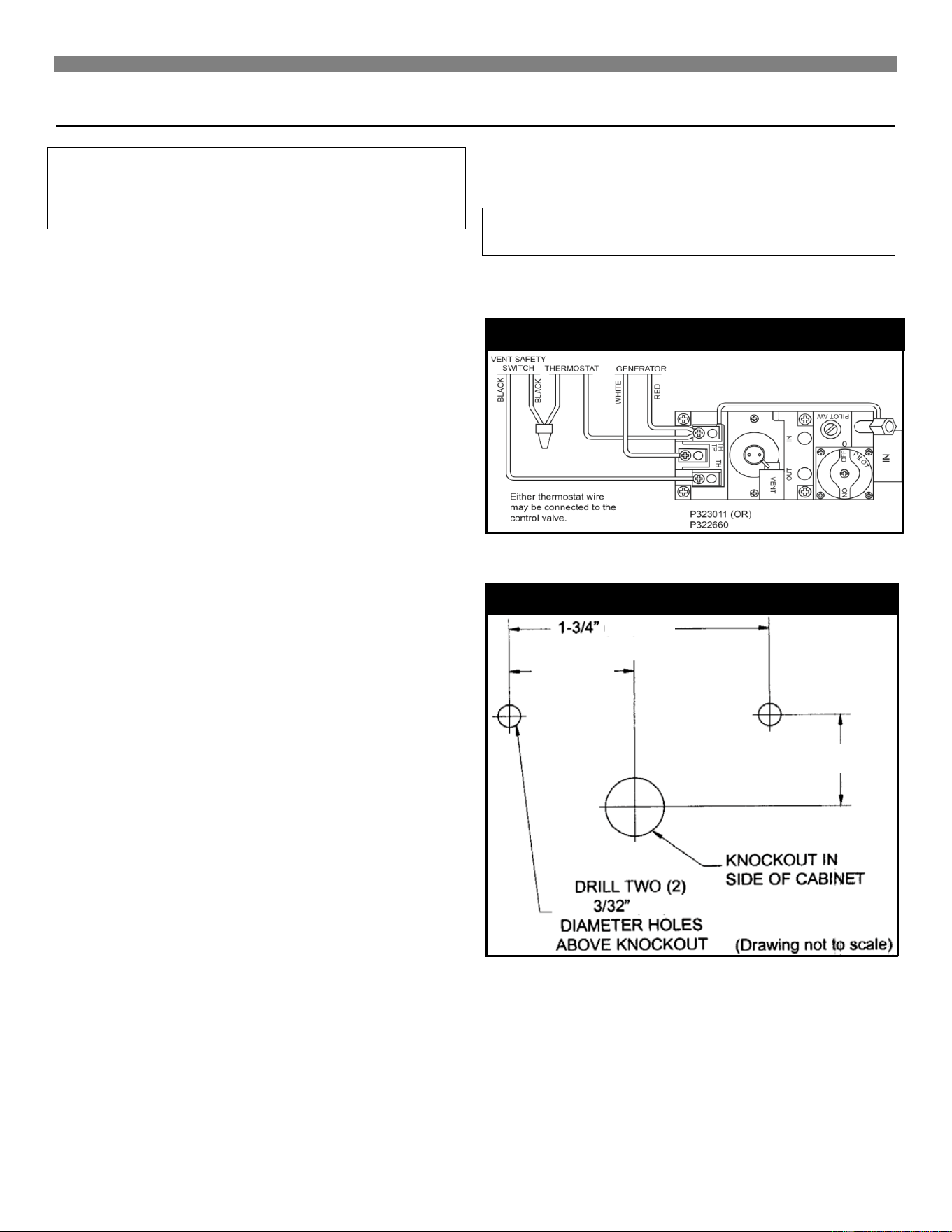
8. Connect the thermostat wires to the control valve as shown in
Figure 12.
Cabinet-Mounted Thermostat Installation
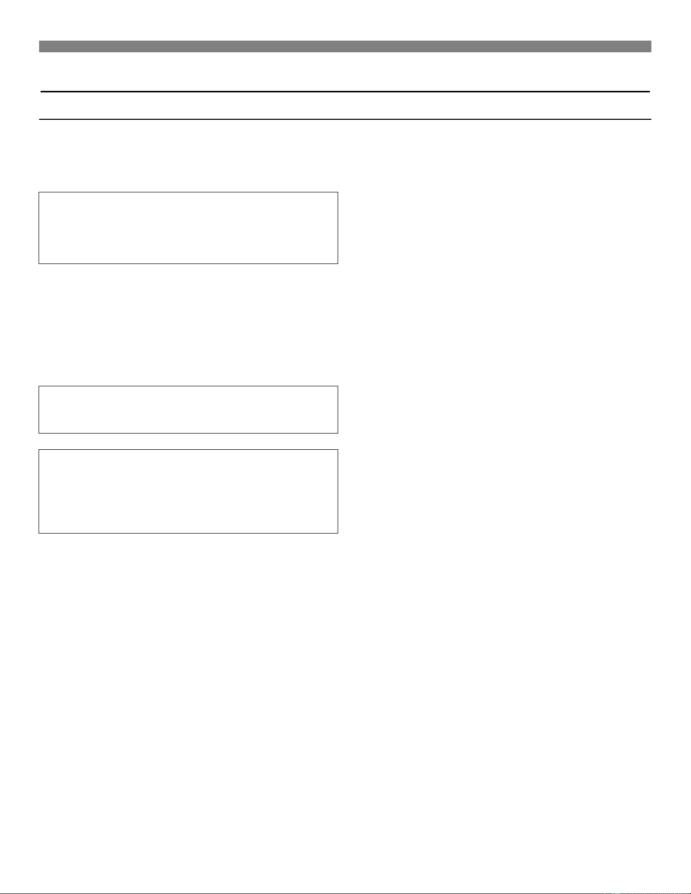
1. Locate the knockout on the right side of the heater to mount
the thermostat. Remove the knockout by taping lightly with a
screwdriver. It will also be necessary to cut the inside panel
insulation about a ½-inch in diameter for clearance to the
knockout.
2. Cut the thermostat wire to the desired length.
3. Connect the thermostat wires to the terminal screws on the
back of the thermostat base.
4. Feed the thermostat wires through the knockout and route
through the metal clip to the gas valve. Models, 2001621 and
2001622 do not have a metal clip.
5. Mount the thermostat to the side of the cabinet with screws
provided.
6. Replace the thermostat cover.
7. Connect the thermostat wires to the control valve as shown in
Figure 5.
IMPORTANT: KEEP THE THERMOSTAT WIRE
AWAY FROM THE COMBUSTION CHAMBER.
FIGURE 12 Thermostat Wiring
FIGURE 13 Cabinet-Mount Clearance
(1.7 mm)
7/8”
(0.87 mm)
19/32”
(0.59 mm)
(0.09 mm)
Installing Your Heater
Vent Installation
This heater must be properly connected to a venting system. This
heater is equipped with a vent safety shutoff system to protect
against improper venting of combustion products. Tampering with
or removal of this control will void the limited warranty and can
result in carbon monoxide (CO) poisoning and possible death.
WARNING: Operation of this heater, when not
connected to a properly installed and maintained
venting system or tampering with the vent safety
shutoff system, can result in carbon monoxide (CO)
poisoning and possible death.
This appliance needs fresh air for safe operation and must be
installed so there are provisions for adequate combustion and
ventilation air. This room heater is equipped with a vent safety
switch. The vent safety switch will cause gas flow to the main
burner to shutoff due to improper venting or a blocked flue. If the
vent safety switch continues to shut off the gas flow, a qualified
service person must be contacted to inspect for improper venting,
blockage in the vent pipe or the vent safety switch for being
defective.
WARNING: Do not bypass the vent safety shutoff
switch. To do so could expose the consumer to
property damage, personal injury or possible death.
WARNING: Danger of illness, bodily injury or death.
This heater and any other fuel burning appliance
must be provided with enough fresh air for proper
combustion and ventilation of flue gases. Most
homes will require that outside air be supplied into
the heater area.
1. An effective flue is necessary to carry off water vapor, carbon
monoxide (CO), carbon dioxide (CO2), and other products of
combustion. For proper venting, follow the following basic
rules for gravity venting, which are:
a. Keep the flue gases hot.
b. Follow the vent manufacturer's installation instructions.
c. Select the proper vent size.
d. Provide constant fresh air replacement.
2. For new installation, it is recommended that a Type “B” vent in
accordance with its’ listing be used. A Type “B” vent is one
made of non-combustible, corrosion resistant material of
sufficient thickness, cross sectional area and heat insulating
quality to avoid excess temperatures on adjacent combustible
material and certified by a nationally recognized testing
agency. Existing brick flues should be lined to provide an
effective vent. Brick chimneys, even in good repair, may be too
large and will not provide sufficient draft to effectively vent a
heater.
3. Use vent pipe of the same size as the outlet on back of heater.
In no case should a different size vent be used. Single wall
vent pipe may be attached directly to the draft hood of the
room heater when a clearance of 2-1/2 inches (64mm) is
maintained between the single wall vent pipe and the
combustible wall of the room in which the room heater is
located. Use double wall vent pipe for clearances less than 2-
1/2 inches (64mm) to combustibles.
4. Avoid a horizontal run to the vent pipe whenever possible.
When a horizontal run is necessary, the pipe must pitch
upward at least 1/4 inch per foot. It must be supported
securely and joints fastened by sheet metal screws or rivets.
Under no circumstances should the vent run downhill.
5. Never put a damper or barometric draft control in a gas vent
pipe.
6. Never end a vent in an open attic or run a vent through a wall
to the outside without extending it upward above the roof.
7. Always terminate the vent with an approved vent cap.
8. ALWAYS SECURE THE VENT PIPE TO THE OUTLET ON
THE BACK OF THE HEATER WITH A SHEET METAL
SCREW.
9. The flue pipe should extend through the wall of a chimney to
be flush with the inner wall.
10. The flue pipe must be adequately supported by metal strips.
11. For the flue pipe running through walls and roofs, use B type
(1 inch (25mm) clearance to combustibles) vent pipe.
12. Vents should extend at least 2 feet (.6m) above the roof and
above any object or nearby building within 10 feet (3m).
13. Open tees should not be used in the flue pipe.
14. The heater must not be connected to a chimney flue that is
servicing a separate solid-fuel burning appliance.
15. For proper venting, do not attach a 90 degree elbow directly to
the draft diverter. It is recommended to attach 2 feet (.6m) of
straight vent pipe before an elbow is used. Use 45 degree
elbows if possible. Run flue pipe as direct as possible with not
more than two elbows.
16. The use of more than one appliance per vent system may
cause the vent safety shutoff device to shut off the heater due
to the cooling of vent temperatures through the draft diverter
of the second appliance.
17. The vent safety shutoff may shut down the heater if a too large
or an unlined, masonry chimney is used. The vent may not
warm quickly enough to get adequate vent action in a chimney
before the shutoff device will shut down the heater. If this is
the case, it is recommended lining the chimney with proper
size type “B” vent pipe or type “B” chimney liner.
18. Single-wall metal pipe should not be used outdoors in cold
climates or venting gas equipment. If the vent is installed
directly outside, the cold pipe may delay the venting and
cause the heater to shut-off by the vent safety switch. To
prevent this problem, as well as condensation of flue products,
an insulated enclosure is recommended. Use type B, vent
pipe and maintain at least a one inch clearance to
combustibles. Use a metal thimble to protect vent pipe as it
passes through combustibles.
Installing Your Heater
14
IMPORTANT: Inspect venting system prior to each heating
season.
Typical Methods of Safely Venting Your Heater
1. Any horizontal run of vent pipe must slope upward a minimum
of 1/4” per foot. Secure all joints of the vent with sheet metal
screws.
2. Where the vent passes through the ceiling or wall, a thimble is
required to keep the ceiling from catching fire. Use only a
thimble designed for use with Type “B” gas vent, certified by a
nationally recognized testing agency.
3. The vertical (straight up and down) part of the vent must end 2
feet above any part of the roof within 10 feet of the vent. This
is to make sure the “draw” of the vent is not obstructed in any
way.
4. A vent cap, approved by a nationally recognized testing
agency, must be installed on top of the vent to keep out rain
and snow and to prevent obstructions of the vent. The vent
cap will also prevent excessive downdraft that can cause
carbon monoxide to enter into the home. Do not use a
homemade vent cap. They are dangerous and can restrict the
draft of the vent.
5. Safe clearances are shown below. To prevent a fire, make
sure the heater is installed no closer than the distances shown
in the figures that apply to your type of venting.
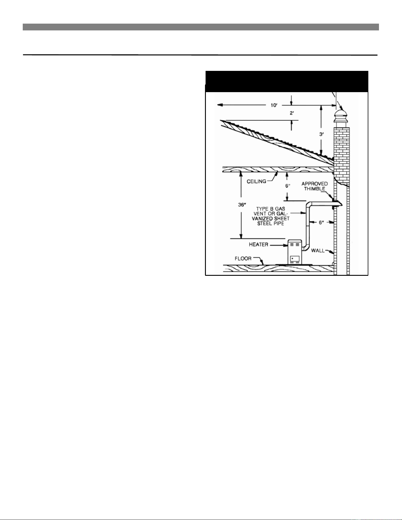
6. If you are venting into a masonry chimney, it must be lined, in
good repair and must not serve a wood or coal burning
appliance. The flue must be at least as large in diameter as
the vent connector. The top of the chimney must be two (2)
feet higher above any part of the roof within ten (10) feet
horizontally of the chimney and must be three (3) feet higher
than the point where it passes through the roof line. If installed
in front of a fireplace, the pipe must pass through a sheet
metal cover on the fireplace that fits tightly.
FIGURE 14 Venting Into A Masonry
Chimney
Installing Your Heater
FIGURE 15 Straight Up Venting With Type
“B” Gas Vent
FIGURE 16 Venting Into An Outside Type
“B” Gas Vent
3 in.
(7 cm)
See Figure
1 “C”
Operating Your Heater
16
Start-Up Procedure
Start the heater using the procedures in the section “Operating
Your Heater”.
WARNING: Danger of bodily injury or death. L.P.
Gas is heavier than air and it will settle in any low
area, including open depressions and it will remain
there unless the area is ventilated.
Never attempt to start-up the unit before thoroughly
ventilating the area.
Check the heater operation as outlined in the following
instructions. If any sparking, odors or unusual noises are
encountered, shut off the electric power immediately. Recheck for
wiring errors or obstructions in or near the fan motor.
CHECK GAS INPUT AND PRESSURES
For heaters located at elevations between sea level and 2,000
feet, the measured input must not be greater than the input shown
on the rating plate of the heater. For elevations above 2,000 feet,
the measured input must not exceed the input on the rating plate
reduced by 4 percent for each 1,000 feet that the heater is above
sea level.
Gas supply pressure and manifold pressure with the burners
operating is specified on the rating plate.
Rated input will be obtained on a heating value of 2,500 Btu/hr. for
propane at 10-inches manifold pressure with factory-sized
orifices. If L.P. Gas having a different heating value is supplied,
orifices must be changed by a qualified service technician before
the heater is operated.
CHECK THERMOSTAT
Check the thermostat operation. When set above room
temperature shown on the thermostat, the main burner should
light. Make certain the thermostat turns off the heater when the
room temperature reaches the selected setting and starts the
heater when the room temperature falls a few degrees.
CHECK THE MANIFOLD GAS PRESSURE
A tapped opening is provided in the gas valve to facilitate
measuring the manifold gas pressure. A "U Tube" manometer
having a scale range from 0 to 12-inches of water should be used
for this measurement. The manifold pressure must be measured
with the burner and pilot operating. Any major changes in flow
must be made by changing the size of the burner orifice.
Check with your local gas supplier for proper orifice sizing.
CHECK THE GAS INPUT (NATURAL GAS ONLY)
WARNING: Natural gas heating value (Btu per
cubic foot) can vary significantly. Therefore, it is
the installer's responsibility to see that Btu/hr. input
to the heater is adjusted properly. Failure to do so
could cause combustion chamber failure,
asphyxiation, fire or explosion resulting in damage,
bodily injury or death. Refer to the National Fuel
Gas Code (NFPA 54) to be sure the heater is
burning fuel at the proper rate.
Under firing could cause inadequate heat, excessive
condensation or ignition problems. Over firing could cause
sooting, flame impingement or overheating of the combustion
chamber.
Before starting natural gas input check, obtain heating value of
the gas (Btu per cubic foot) at standard conditions from your local
supplier.
To measure the input, using the gas meter, proceed as follows:
1. Turn off gas supply to all other appliances except the heater.
2. With the heater operating, time the smallest dial on the meter
for one complete revolution. If this is a 2-cubic-foot dial, divide
the seconds by 2. If this is a 1-cubic-foot dial, use the time in
seconds as is (3,600 = Sec/hr.). This gives the seconds per
cubic foot of gas being delivered to the heater.
3. Assuming natural gas with a heating value of 1,000 Btu per
cubic foot and 34-seconds per cubic foot used as determined
by step (2), then:
Input = 1,000 x 3,600 / 34 = 106,000 Btu/hr.
This measured input must not be greater than the input
indicated on the nameplate of the heater.
4. Relight all other appliances turned off in Step 1 above. Be
sure all pilots are operating.
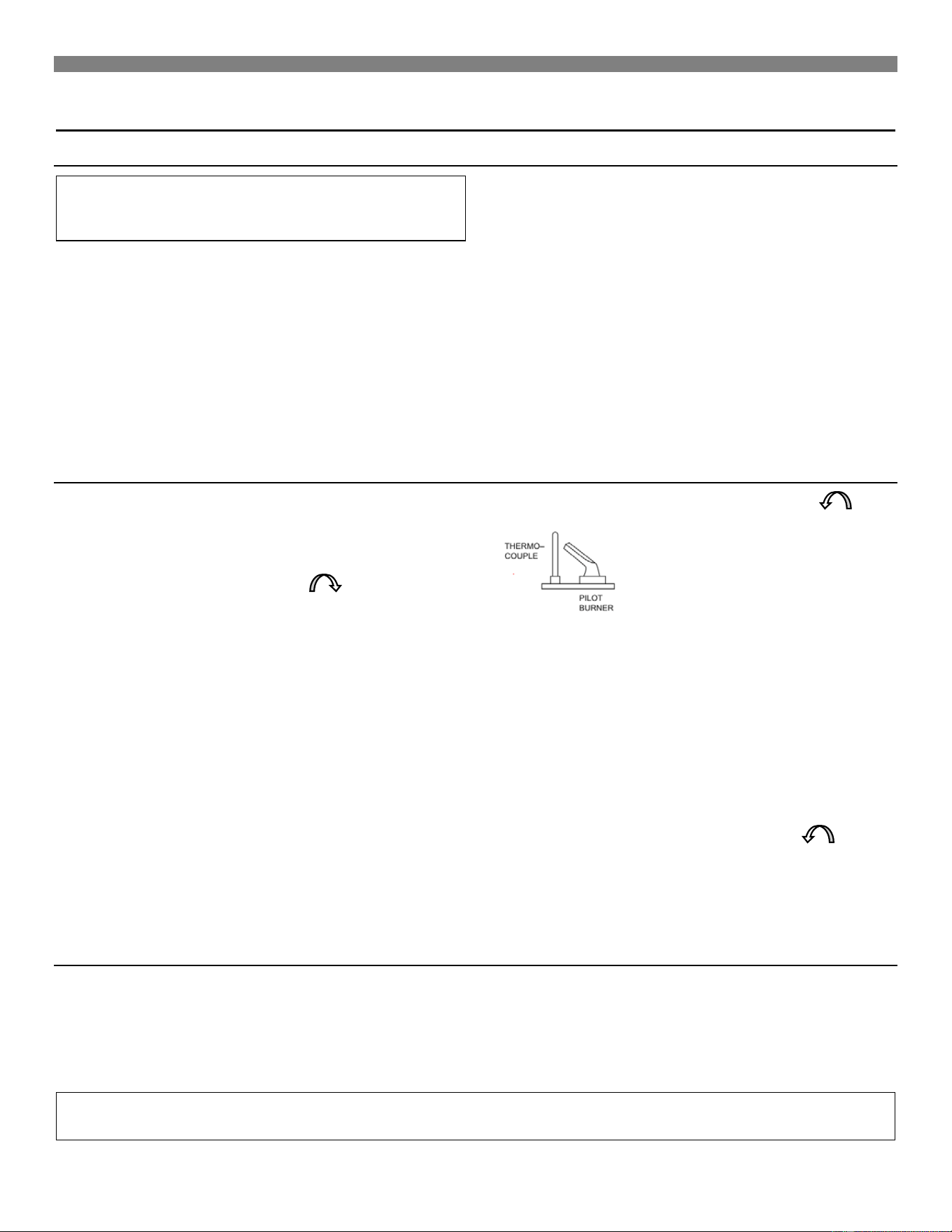
CHECK PILOT BURNER
The pilot flame must envelop 1/2- to 5/8-inches of the generator.
Pilot flame is preset at the factory, so ordinarily does not require
field adjustment. (Figure 17). On new installations, the gas lines
will be filled with air and may take several minutes to establish a
pilot flame.
Type of Gas
Manifold Pressure, In. W.C.
Natural
4.0″
L . P.
10.0″
FIGURE 17 Pilot Burner
Operating Your Heater
Burner Flame Characteristics
Start the heater and let it operate for at least 10 minutes. Open
the access door to view the burner flame. Limit your movements
near the heater a few more minutes before making your final
observation. The flame may look yellow due to dust particles in
the room air. The flame should change to a nice blue color with
firm inner and secondary cones. An occasional flash of orange
might be seen as dust particles burn in the flame. This is normal.
No burner adjustment is provided, or is necessary. (Figure 18).
Normal Appearance
Natural Gas:
1. Inner cone- blue color - 3/8 to 5/8-inch above ports.
2. Secondary inner cone - light blue - 1 to 2-inches above ports.
3. Total flame - from blue to nearly invisible - approximately 6-
inches above ports.
L.P Gas:
1. Inner cone - blue color - 1/2 to 3/4-inch above ports.
2. Secondary inner cone - light blue - 1 to 2-inches above ports.
3. Total flame - from blue to nearly invisible - approximately 6-
inches above ports.
Abnormal Appearance
Lazy Flame:
Long soft yellow cones moving around in the combustion chamber
lifting from ports (insufficient air).
Extremely Fast Flame:
Will not hold to ports - entire cone sections blow off from noisy
ports (too much pressure).
WARNING: If the flame appears abnormal, contact
the gas company or a qualified service technician
immediately.
WARNING: Natural gas heating value (Btu per cubic
foot) can vary significantly; therefore, it is the installer’s
responsibility to see that the Btu input to the heater is
adjusted properly. Failure to do so could cause
combustion chamber failure, asphyxiation, fire or
explosion, resulting in property damage, bodily injury or
death. Refer to the National Fuel Code (NFPA-54) to be
sure the heater is burning fuel at the proper rate.
Gas Conversion Kits
Gas Conversion Kits
Natural Gas to L.P. Gas
Model
Description
8945
200 Series
8946
350 Series
8947
500 Series
8948
650 Series
Gas Conversion kits
L.P. Gas to Natural Gas
Model
Description
8949
200 Series
8950
350 Series
8951
500 Series
8952
650 Series
FIGURE 18 Burner Flame Characteristics
Operating Your Heater
18
FOR YOUR SAFETY, READ BEFORE LIGHTING
WARNING: If you do not follow these instructions
exactly, a fire or explosion may result causing
property damage, personal injury or loss of life.
A. This appliance has a pilot which must be lighted by hand.
When lighting the pilot, follow these Instructions exactly.
B. BEFORE LIGHTING smell around the appliance area for
gas. Be sure to smell next to the floor because some gas is
heavier than air and will settle on the floor.
WHAT TO DO IF YOU SMELL GAS
• Do not try to light any appliance or strike a match.
• Do not touch any electric switch; do not use any phone or cell
phone in your building.
• Immediately call your gas supplier from a neighbor's phone.
Follow the gas supplier's instructions.
• If you cannot reach your gas supplier, call the fire department.
C. Use only your hand to push in or turn the gas control knob.
Never use tools. If the knob will not push in or turn by hand,
don't try to repair it, call a qualified service technician. Force
or attempted repair may result in a fire or explosion.
D. Do not use this appliance if any part has been under water.
Immediately call a qualified service technician to inspect the
appliance and to replace any part of the control system and
any gas control which has been under water.
NOTE: FOR ADDITIONAL INFORMATION REFER TO THE
INSTALLATION AND OPERATION INSTRUCTION MANUAL
SUPPLIED WITH THIS APPLIANCE OR CONTACT THE
MANUFACTURER IDENTIFYING THE PRODUCT BY ITS MODEL
NUMBER LOCATED ON THE RATING PLATE, FOUND NEAR THE
GAS VALVE.
OPERATING INSTRUCTIONS
1. STOP! Read the safety information above.
2. Set the thermostat to the lowest setting.
3. If applicable, turn off all electric power to the appliance.
4. Remove the control access panel.
5. Turn the gas control knob clockwise to "OFF".
NOTE: Knob cannot be turned from “PILOT” to “OFF” unless
knob is pushed in slightly. Do not use force.
6. Wait five (5) minutes to clear out any gas, then smell for
gas, including near the floor. If you then smell gas, stop!
Follow "B" In the safety information above. If you don't
smell gas, go to the next step.
7. Loosen wing nut and open the pilot observation door (If
equipped).
8. To f ind the pilot, follow the metal tube from the gas control
valve. The pilot is mounted on the side of the burner.
9. Turn knob on the gas control counterclockwise to
"PILOT."
10. Push in the control knob all the way and hold in.
Immediately light the pilot. Continue to hold the control
knob in for about one (1) minute after the pilot is lit.
Release the knob and it will pop back up. The pilot should
remain lit. If it goes out, repeat Steps 5 through 10.
• If the button does not pop up when released, stop and
immediately call your service technician or gas supplier.
• If the pilot will not stay lit after several tries, turn the gas
control knob to "OFF" and call your service technician or gas
supplier.
11. Close the pilot observation door and tighten the wing nut (if
equipped).
12. Turn the gas control knob counterclockwise to "ON".
13. Replace the control access panel.
14. Turn on all electric power to the appliance.
15. Set the thermostat to the desired setting.
TO TURN OFF GAS TO APPLIANCE
1. Set the thermostat to the lowest setting.
2. Turn off all electric power to the appliance if service is to be performed.
3. Remove the control access panel.
4. Push in the gas control knob slightly and turn it clockwise to "OFF". Do not Force.
5. Replace the control access panel.
IMPORTANT: KEEP BURNER AND CONTROL COMPARTMENT CLEAN.
WARNING: DUE TO HIGH SURFACE TEMPERATURES - KEEP CHILDREN, CLOTHING, FURNITURE
OR ANY COMBUSTIBLE MATERIAL AWAY FROM THE HEATER.
Caring for Your Heater
Care – 19
How To Care For Your Heater
WARNING: Danger of bodily injury or death. Turn
off electric power supply at the disconnect switch,
fuse box or service panel before removing any
doors or access or service panels from the unit.
CABINET FINISH
Clean the cabinet with a damp rag. Never use abrasive cleaners.
Cabinets are finished in heat resistant powder coated finish - DO
NOT refinish with wall paint.
REMOVABLE CABINET TOP (350, 500, & 650 MODEL SERIES)
For ease of cleaning, access or replacement of internal parts, the
top of this heater can be removed by following these steps:
1. Remove the three (3) brackets on the rear of the heater
securing the cabinet top to the back plate.
2. Pull the cabinet top forward and lift up. Reinstall the cabinet
top by reversing the procedures noted above. (Figure 19).
Note: Take special care to engage the six (6) clips located on the
bottom of the cabinet top into the top flange of the heater sides.
HEATER AREA
Keep the area near the heater clear and free from combustible
materials, gasoline and other flammable liquids and vapors.
COMBUSTION AND VENTILATION AIR
The combustion and ventilation air supply must not be blocked.
Do not put anything in or on the heater cabinet.
For better circulation and more effective heating, do not place
obstructions, furniture or other items closer than four feet to the
front of the cabinet or two feet from each side of the cabinet.
ANNUAL UPKEEP NEEDED
It is recommended that a qualified service technician perform
these checks at the beginning of each heating season.
CLEANING BLOWER (IF EQUIPPED)
Shut off electricity. Clean any lint or dirt from fan blades, fan motor
and exposed air passages. Annually put two drops of SAE 20 oil
in each of the two cups or oil tubes.
PILOT BURNER
Light the pilot using the instructions in OPERATING YOUR
HEATER. Leave the thermostat at the lowest setting.
The pilot flame should surround 1/2 to 5/8 inches of the generator
tip. If the flame needs adjusting, do it as follows:
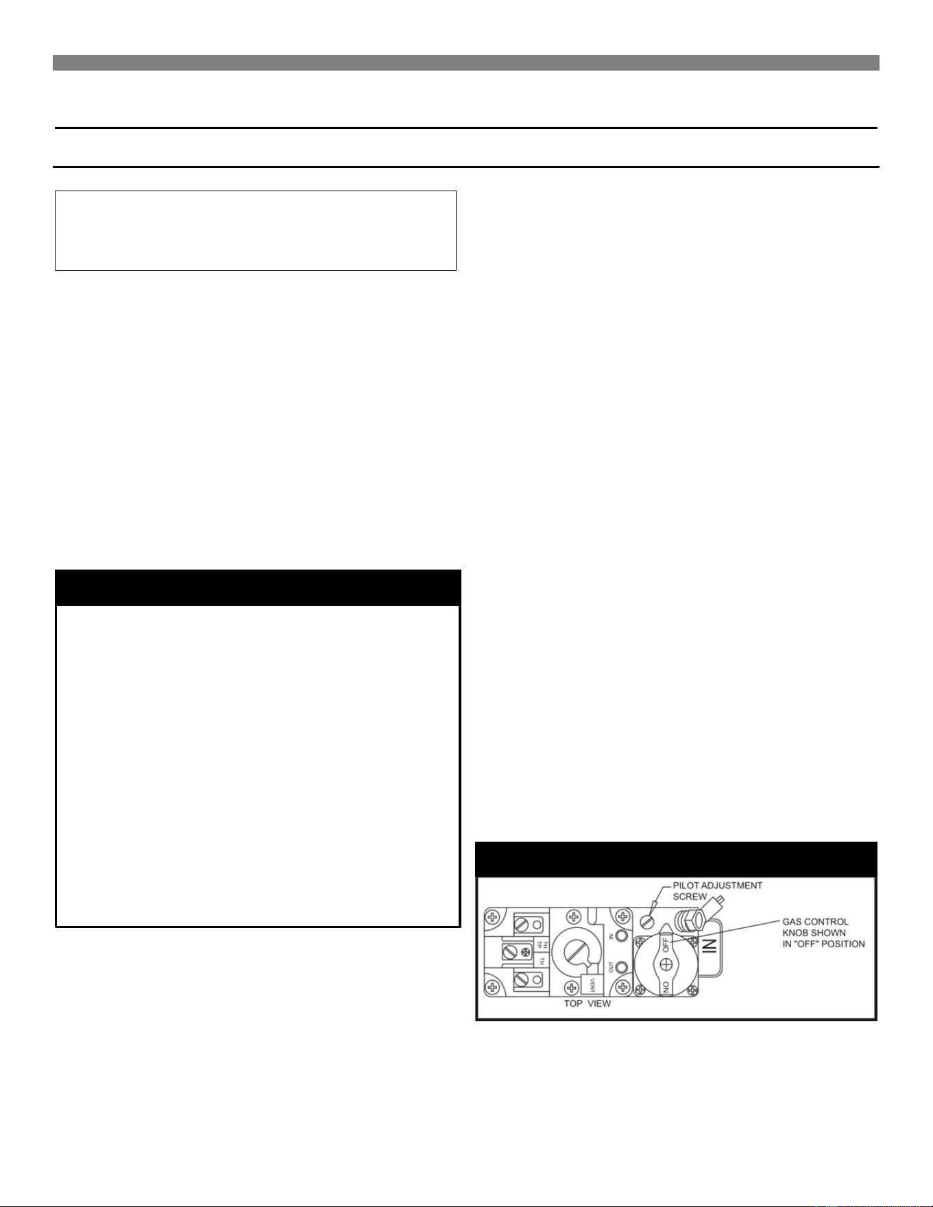
ADJUST PILOT BURNER
1. Insert a small screwdriver, adjust the flame as needed. Turn
the screw counterclockwise to increase the flame, clockwise to
decrease.
2. Turn the thermostat to the highest setting. The main burners
should light quickly and smoothly. Turn the thermostat to its
lowest setting. Main burners should go out. The pilot should
remain lit.
3. Refer to Figure 20.
VENTING SYSTEM
Make sure that no parts of the vent air system are blocked, rusted
or damaged. Clean or replace before using the heater.
BURNER CLEANING
Check the burner. If cleaning is required, contact a qualified
service technician to clean and service burner.
FIGURE 19 Removable Cabinet Top
FIGURE 20 Pilot Adjustment Screw
Caring for Your Heater
20
CLEANING BURNER COMPARTMENT
Because cold air is attracted to the flame during heater operation,
a build up of lint from carpeting, bedding, dust, etc. in the burner
area will occur. It is necessary to clean this area regularly. Use a
vacuum cleaner with a narrow attachment to reach small areas.
Be careful in and around the pilot. A change in its adjustment
could be made if moved during cleaning.
DANGER: A build up of any dust, lint or foreign
material in the primary air opening of the burner
can interfere with the proper air gas mixture and
can result in a yellow flame which can produce
carbon monoxide and soot. This condition if
allowed to develop, can lead to bodily injury
including death. It is imperative that the burner be
kept clean.
TO REMOVE LOGS FROM COMBUSTION CHAMBER
Always remove the logs from the combustion chamber when
cleaning the burner or combustion chamber.
1. As parts are removed, place them in a safe place until ready
for reassembly.
2. Remove the chrome hearth assembly. Compression clips hold
hearth assembly in place. Grasp the assembly frame and pull
forward.
3. Remove the screws in the glass window frame.
IMPORTANT: The logs are made of special
lightweight materials that can be easily damaged by
rough handling.
4. Lift the front log up and out of the front log support brackets
carefully. Take care when pulling it out through the window
opening. Do not scrape it against the metal edges of the
opening.
5. Remove the screws and plates holding the top right and the
top left sides of the rear log set against the top rear support
brackets.
6. Lift the rear log set up and out of the bottom support brackets.
Tilt the top towards the back and slowly allow the bottom to
pass through the opening first. Take care not to scrape it
against the metal edges of the opening.
7. Reverse the above procedure to reassemble after cleaning.
GLASS CLEANING
Use mild soap and water only. Never clean when the glass is hot.
If the glass is broken it must be replaced with the manufacturer’s
authorized part only. Failure to do so could cause property
damage, bodily injury or death.
NOTE: A properly adjusted burner with nearly all
gases will produce a flame which has a clear blue
cone having a bluish-red or bluish-violet outer
mantle.
FIGURE 21 Log Mounting
Replacement Parts
Accessories– 21
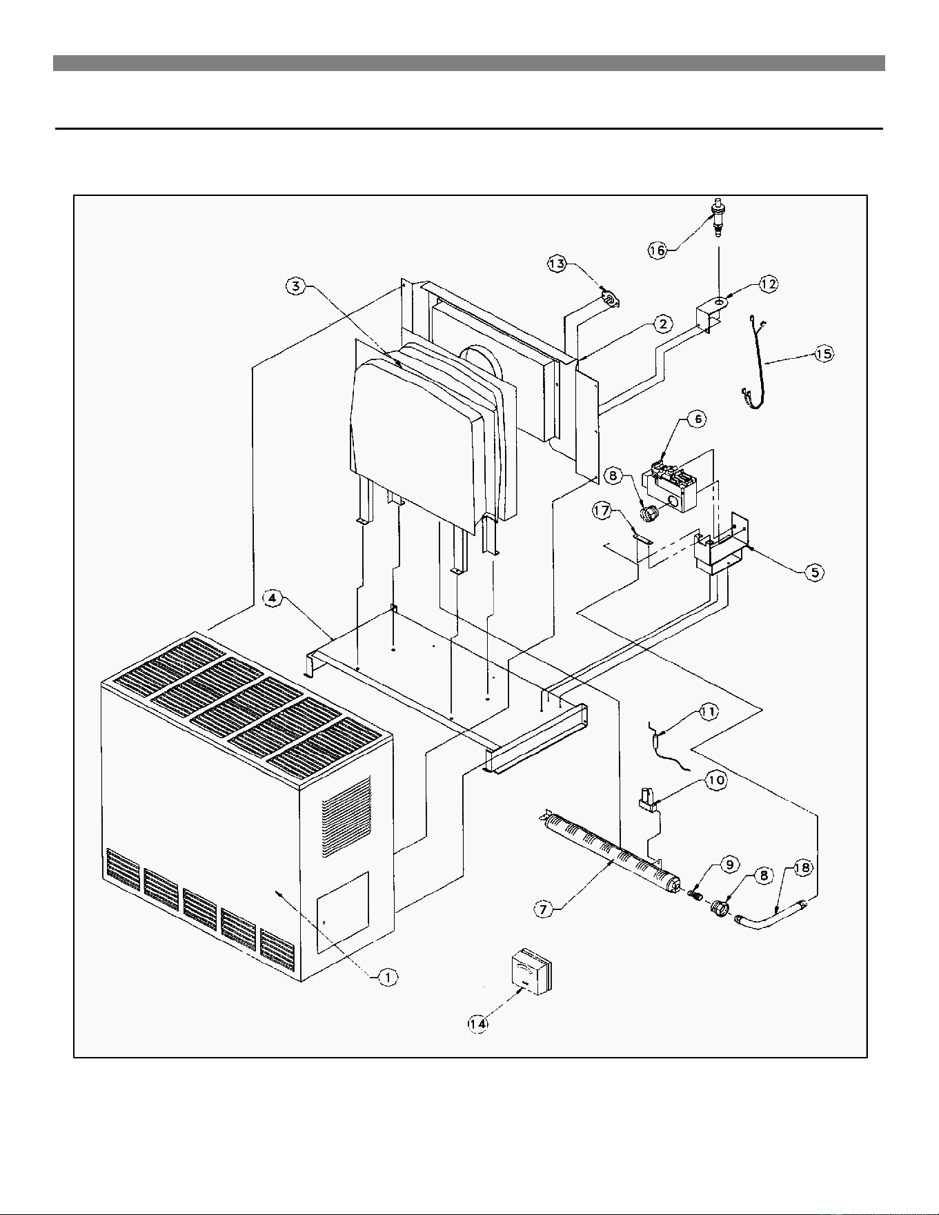
FOR MODELS: 2001621A; 2011621A; 2031621A; 2051621A; 2001622A; 2011622A; 2031622A; 2051622A
FOR PART LIST SEE PAGE 22.
Replacements Parts
22
REPLACEMENT PARTS LIST FOR MODELS 2001621A; 2011621A; 2031621A; 2051621A; 2001622A; 2011622A; 2031622A;
2051622A
Ref.
Number
Description
PART NO. FOR MODEL
2001621A; 2011621A;
2031621A; 2051621A
2001622A; 2011622A;
2031622A; 2051622A
1
Wrapper Assembly
K000275
K000275
2
Draft Diverter Assembly
K000274
K000274
3
Combustion Chamber
8957
8957
4
Base Plate
K000265
K000265
5
Valve Bracket
K000850
K000850
6
Control Valve
P322660
P323011
7
Burner
K000851
K000851
8
Orifice Fitting
P500086
P500086
9
Burner Orifice
P501800
P501781
10
Pilot
P323073
P323074
11
Thermocouple
P043800
P043800
12
Igniter Bracket
7A189
7A189
13
Vent Safety Switch
P323663
P323663
14
Thermostat
P322016
P322016
15
Wire Assembly
P500409
P500409
16
Manual Spark Igniter
P285500
P285500
17 Manifold Plate K000852 K000852
18
Manifold Assembly
P323681
P323681
For part illustration, see page 21.
Note: Screws and bolts are standard hardware items, available locally.
Replacement Parts
Accessories– 23
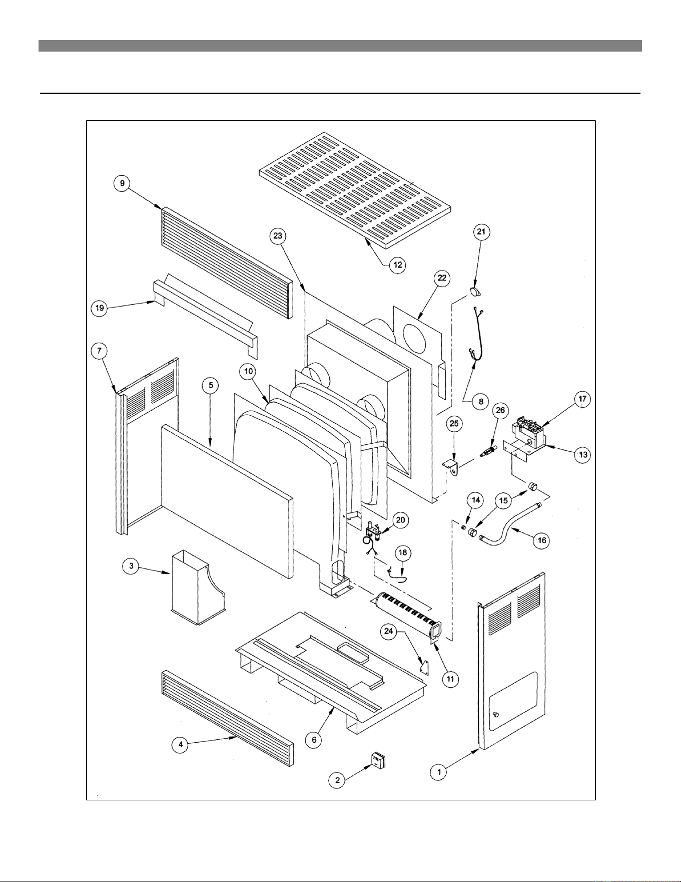
ENCLOSED FRONT
FOR PART LIST SEE PAGE 24.
Replacements Parts
24
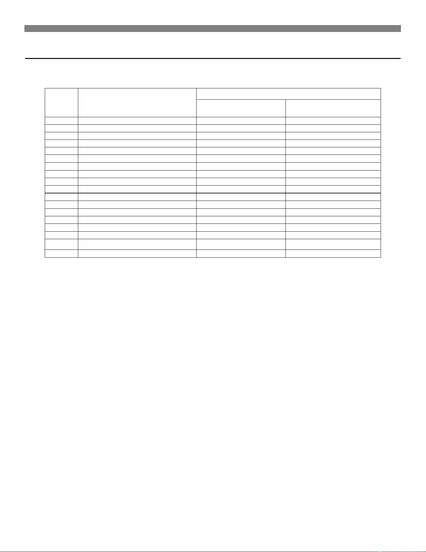
REPLACEMENT PARTS LIST FOR ENCLOSED FRONT
For part illustration, see page 23.
Note: Screws and bolts are standard hardware items, available locally.
Ref.
Number
Description
PART NO. FOR MODEL
3501522A
3511522A
3531522A
3551522A
3501922A
3511922A
3531922A
3551922A
3501521A
3511521A
3531521A
3551521A
3501921A
3511921A
3531921A
3551921A
5001522A
5011522A
5031522A
5051522A
5001922A
5011922A
5031922A
5051922A
5001521A
5011521A
5031521A
5051521A
5001921A
5011921A
5031921A
5051921A
6501522A
6511522A
6531522A
6551522A
6501922A
6511922A
6531922A
6551922A
6501521A
6511521A
6531521A
6551521A
6501921A
6511921A
6531921A
6551921A
1
Panel Side Right
K000204
K000204
K000205
K000205
K000206
K000206
2
Thermostat
P322016
P322016
P322016
P322016
P322016
P322016
3
Inlet Duct
K7000-6022
K7000-6022
K7000-6022
K7000-6022
K7000-6022
K7000-6022
4
Bottom Louver Assembly
K000182-1
K000182-1
K000182-2
K000182-2
K000182-3
K000182-3
5
Center Panel
K000220
K000220
K000221
K000221
K000222
K000222
6
Cabinet Bottom
K5000-6003
K5000-6003
K5000-6004
K5000-6004
K5000-6019
K5000-6019
7
Panel Side Left
K000207
K000207
K000208
K000208
K000209
K000209
8
Wire Assembly
P500409
P500409
P500416
P500416
P500416
P500416
9
Top Louver Assembly
K000181
K000181
K000212-1
K000212-1
K000212-2
K000212-2
10
Combustion Chamber
8958
8958
8960
8960
8962
8962
11
Burner
P501620
P501620
P501621
P501621
P501622
P501622
12
Cabinet Top
K000223
K000223
K000224
K000224
K000225
K000225
13
Control Bracket
K000147
K000147
K000147
K000147
K000147
K000147
14
Orifice
P500336
P500351
P500330
P500345
P500327
P500432
15
Orifice Fitting
P500086
P500086
P500086
P500086
P500086
P500086
16
Manifold Assembly
P323678
P323678
P323679
P323679
P323680
P323680
17
Gas Control Valve
P323011
P322660
P323011
P322660
P323011
P322660
18
Thermocouple
P043801
P043801
P043801
P043801
P043801
P043801
19
Shield Cover
-
-
K7011-6030
K0711-6030
-
-
20
Pilot
P323074
P323073
P323074
P323073
P323074
P323073
21
Vent Safety Switch
P323663
P323663
P323664
P323664
P323664
P323664
22
Heat Shield (Rear)
K7003-6370
K7003-6370
K7003-6371
K7003-6371
K7003-6372
K7003-6372
23
Back Plate
K000309
K000309
K000310
K000310
K000526
K000526
24
Rear Corner Brace
K7003-6097
K7003-6097
K7003-6097
K7003-6097
K7003-6097
K7003-6097
25
Bracket
7A189
7A189
7A189
7A189
7A189
7A189
26
Manual Spark Igniter
P285500
P285500
P285500
P285500
P285500
P285500
Replacement Parts
Accessories– 25
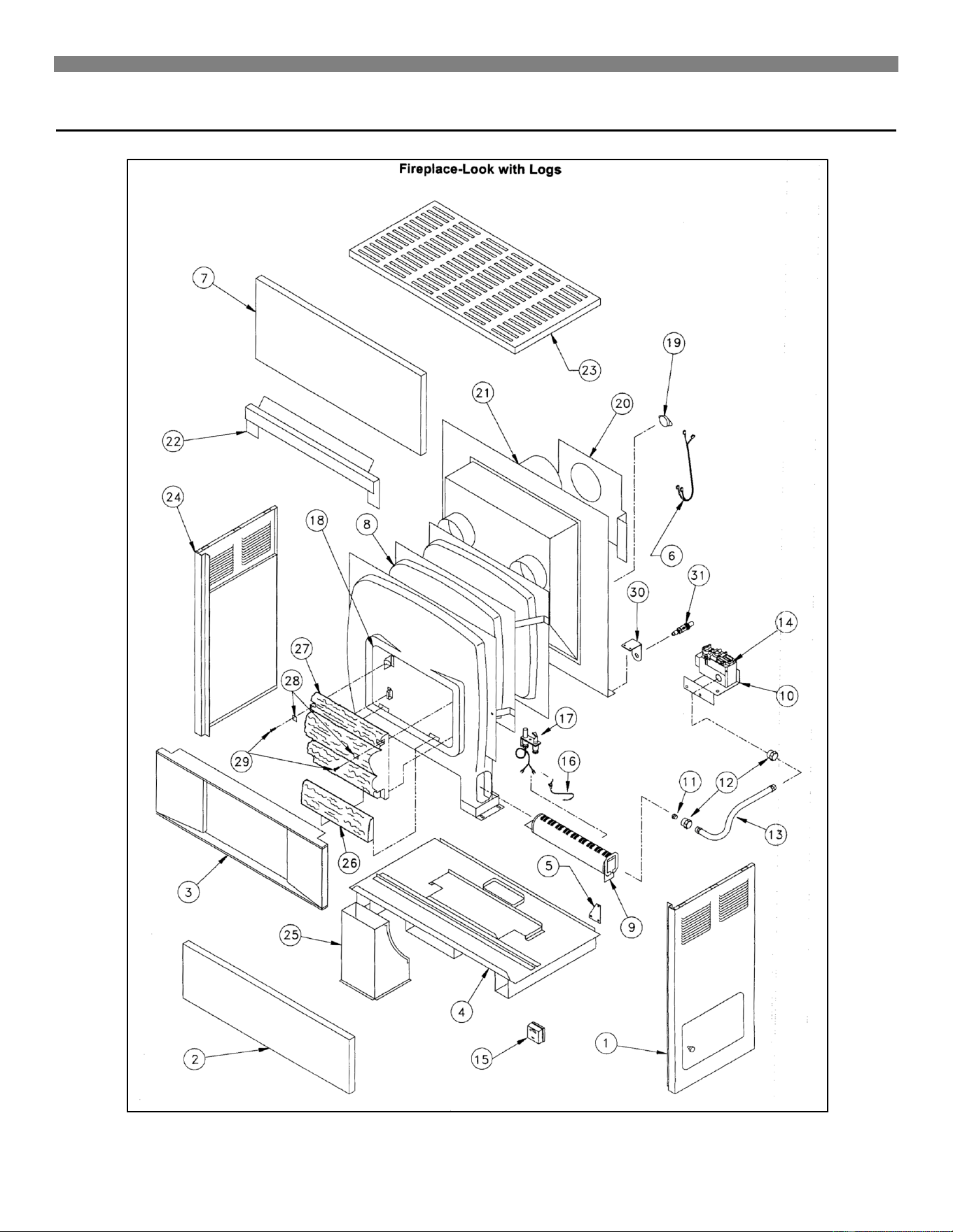
FIREPLACE-LOOK WITH LOGS
FOR PART LIST SEE PAGE 26.
Replacements Parts
26
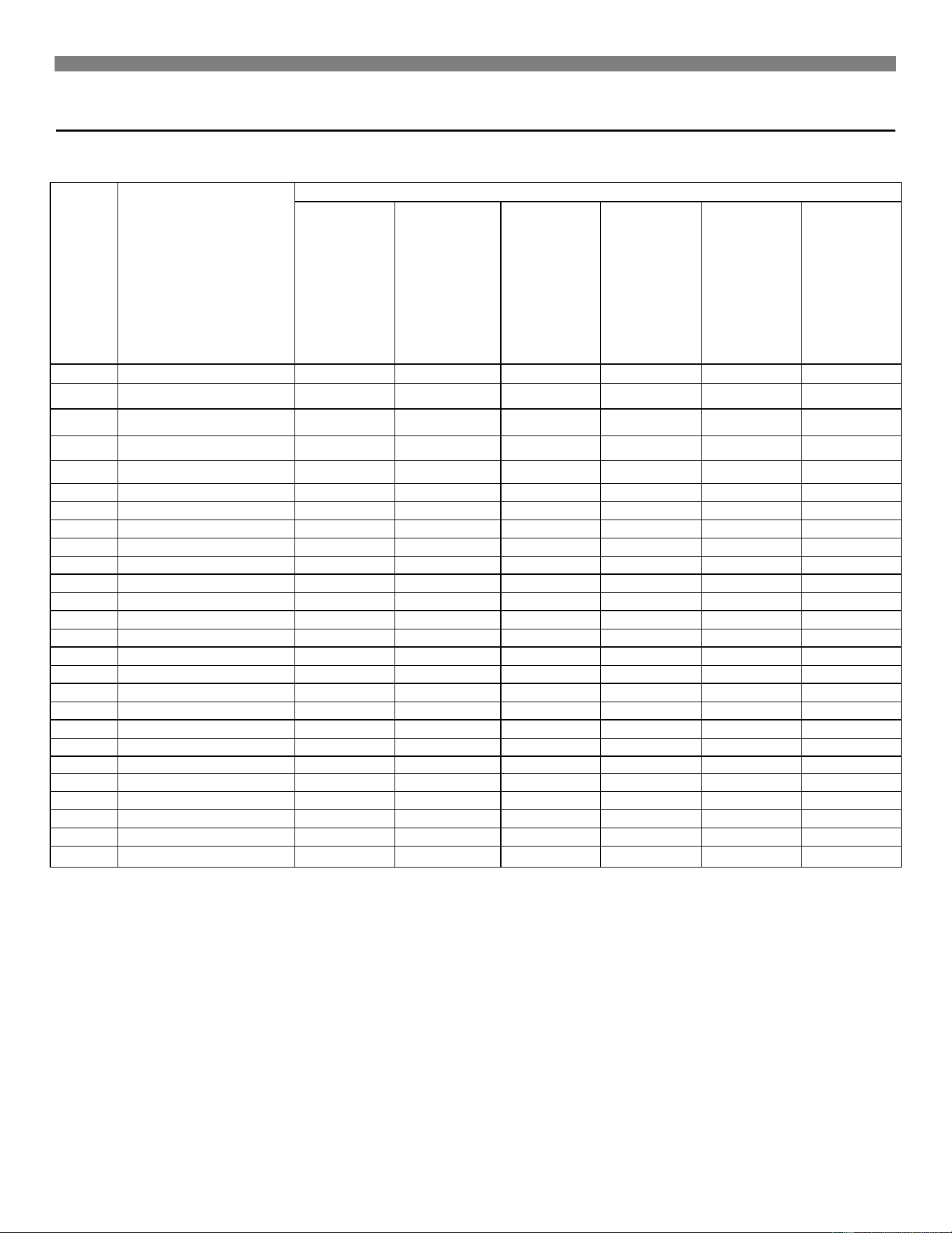
REPLACEMENT PARTS LIST FOR FIREPLACE-LOOK WITH LOGS
For part illustration, see page 25.
Note: Screws and bolts are standard hardware items, available locally.
Ref.
Number
Description
PART NO. FOR MODEL
3502522A
3512522A
3532522A
3552522A
3502922A
3512922A
3532922A
3552922A
3502521A
3512521A
3532521A
3552521A
3502921A
3512921A
3532921A
3552921A
5002522A
5012522A
5032522A
5052522A
5002922A
5012922A
5032922A
5052922A
5002521A
5012521A
5032521A
5052521A
5002921A
5011921A
5032921A
5052921A
6502522A
6512522A
6532522A
6552522A
6502922A
6512922A
6532922A
6552922A
6502521A
6512521A
6532521A
6552521A
6502921A
6512921A
6532921A
6552921A
1
Panel Side Right
K000204
K000204
K000205
K000205
K000206
K000206
2
Bottom Panel
K000229
K000229
K000230
K000230
K000231
K000231
3
Hearth
K000462
K000462
K000463
K000463
K000464
K000464
4
Cabinet Bottom
K5000-6003
K5000-6003
K5000-6004
K5000-6004
K5000-6019
K5000-6019
5
Rear Corner Brace
K7003-6097
K7003-6097
K7003-6097
K7003-6097
K7003-6097
K7003-6097
6
Wire Assembly
P500409
P500409
P500416
P500416
P500416
P500416
7
Top Panel
K000232
K000232
K000233
K000233
K000234
K000234
8
Combustion Chamber
8959
8959
8961
8961
8963
8963
9
Burner
P501620
P501620
P501621
P501621
P501622
P501622
10
Control Bracket
K000147
K000147
K000147
K000147
K000147
K000147
11
Burner Orifice
P500336
P500351
P500330
P500345
P500327
P500432
12
Orifice Fitting
P500086
P500086
P500086
P500086
P500086
P500086
13
Manifold Assembly
P323678
P323678
P323679
P323679
P323680
P323680
14
Gas Control Valve
P323011
P322660
P323011
P322660
P323011
P322660
15
Thermostat
P322016
P322016
P322016
P322016
P322016
P322016
16
Thermocouple
P043801
P043801
P043801
P043801
P043801
P043801
17
Pilot
P323074
P323073
P323074
P323073
P323074
P323073
18
Window Assembly
K000450
K000450
K000451
K000451
K000452
K000452
19
Vent Safety Switch
P323663
P323663
P500406
P500406
P323663
P323663
20
Heat Shield
K7003-6370
K7003-6370
K7003-6371
K7003-6371
K7003-6372
K7003-6372
21
Back Plate
K000309
K000309
K000527
K000527
K000311
K000311
22
Shield Cover
-
-
K7011-6030
K7011-6030
K7011-6031
K7011-6031
23
Cabinet Top
K000223
K000223
K000224
K000224
K000225
K000225
24
Panel Side Left
K000207
K000207
K000208
K000208
K000209
K000209
25
Inlet Duct
K7000-6022
K7000-6022
K7000-6022
K7000-6022
K7000-6022
K7000-6022
26
Front Log
P500678
P500678
P500679
P500679
P500680
P500680
27
Rear Log Set
P500674
P500674
P500675
P500675
P500676
P500676
29
Stainless Steel Screw (2
P103200
P103200
P103200
P103200
P103200
P103200
30
Bracket
7A189
7A189
7A189
7A189
7A189
7A189
31
Manual Spark Igniter
P285500
P285500
P285500
P285500
P285500
P285500

Blower Accessory 2102
Accessories– 27
Mounting the Blower
Note: All electrical work must conform to your local codes and ordinances or in their absence, with National Electrical Code,
ANSI/NFPA 70. If you are not familiar with wiring codes in general, have a competent electrician do this job. In CANADA: CANADIAN
ELECTRICAL CODE C22.1.
WARNING: Danger of property damage, bodily injury or death. Turn off electrical power supply at
disconnect switch, fuse box or service panel before removing or working on fan.
1. Place the motor and blower on the heater floor, securing with four (4) screws. Attach three (3) screws to the inlet duct and one (1)
screw to the heater floor, using the existing screw holes. Align the opening in the base of the motor and blower with the opening in
the heater floor. The opening on the side of the motor and blower should align with the opening on the heater inlet duct.
2. Attach the “HI” and “LO” speed switch to the upper left corner on the back of the heater and replace the corner bracket with the
speed switch plate using the existing mounting holes. The correct position for the fan switch is shown below. The top of the fan
switch should be level with the notch directly across the switch on the blower mounting plate. Make sure speed switch wires are
secured with clamp (provided in the kit) away from the combustion chamber before operating the heater.
Wiring
Attach clamp to secure wires
Air Inlet Duct
Correct position
of fan switch
Run switch wire
through attached clamp
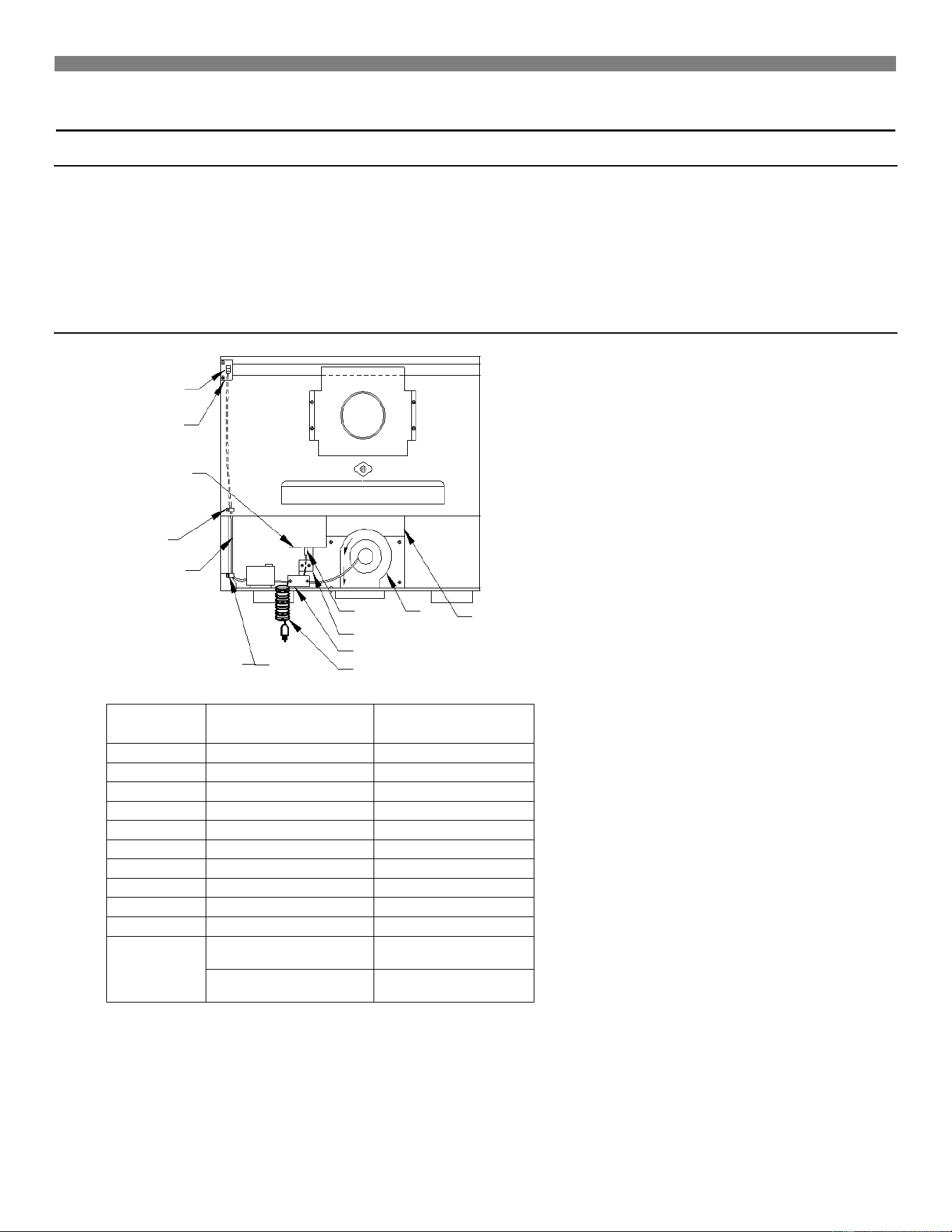
Blower Accessory 2102
28
Operation
This accessory is operated using the factory equipped, three-prong (grounding) plug and cord. When using the plug and cord, for your
protection against shock hazard, it must be plugged directly into a properly grounded three-prong receptacle. DO NOT CUT OR
REMOVE THE PRONG.
You must select “HI” or “LO” on the speed switch (item 8) for automatic blower operation. When the heater heats up, the fan switch is
activated and the blower will operate. When the heater cools down, the blower will turn off. The blower will not operate if the speed
switch is set in the “OFF” (center) position.
Replacement Parts
Reference
Number
Part Number
Description
1
P501779
Motor
2
P323096
Fan Switch
3
K000862
Fan Switch Plate
4
90-01005-000-02
Junction Box
5
P501778
Cord and Plug
6
P202900
Wire (Red)
6
P202800
Wire (Black)
6
P202700
Wire (Blue)
7
K000862
Speed Switch Plate
8
P320911A
Speed Switch
Not shown
K000868
Switch Mounting
Bracket – 500 Series
K000870
Switch Mounting
Bracket – 650 Series
7
2
5
Air Inlet
Duct
Correct
position of
fan switch
Run switch
wire through
attached clamp
4
6
3
8
1
Attach clamp
to secure
wires
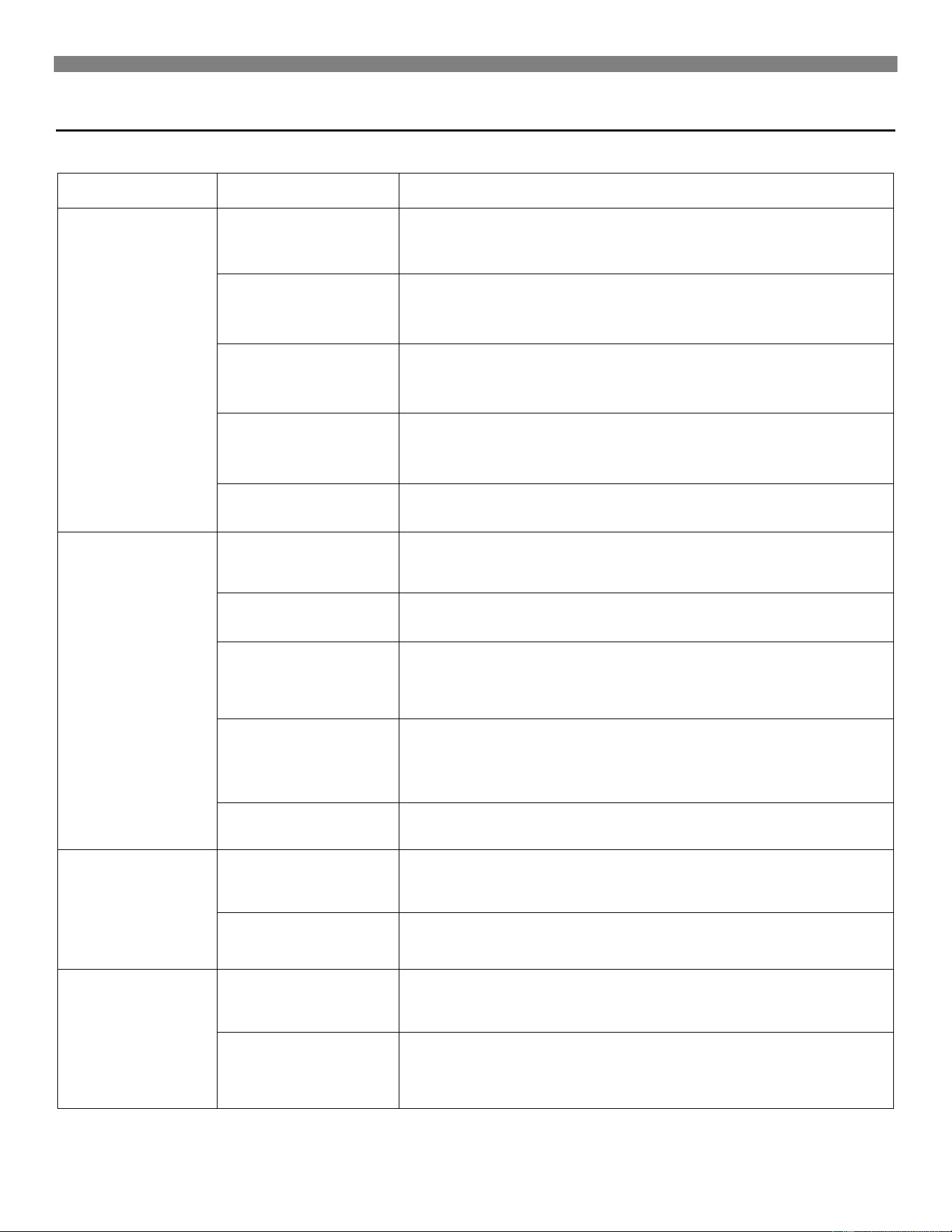
Troubleshooting
SYMPTOM POSSIBLE CAUSE CORRECTIVE ACTION
1. Pilot will not stay lit
after following
lighting instructions.
A. Generator producing
insufficient millivolts.
Check pilot flame – it must impinge on the generator from 1/4 to 3/8-inches .
Be sure the thermocouple is fully inserted in its bracket.
B. Loose or dirty
generator
connections at gas
valve.
Clean and/or tighten the connections at the valve.
C. Generator defective.
Check the generator with millivolt meter. Take reading at the generator
terminals of the valve with the valve placed in "Pilot" position. Disconnect the
thermostat wires. The millivolt reading should be 450 millivolts or more.
D. Grounded thermostat
wire.
Remove the thermostat wires from the valve terminals.
If the pilot now stays lit, trace the thermostat wiring circuit for a ground. May
be grounded to heater, gas supply, nails or staples.
E. Defective valve. Replace the gas valve after above is verified.
2. Pilot burning - no
gas to the main
burner.
A. Thermostat not turned
to a position calling
for heat.
Set the thermostat to a position calling for heat.
B. Plugged burner
orifice.
Clean or replace.
C. Improperly wired or
broken thermostat
wires.
Defective thermostat.
Check the connections at valve terminals. If
valve operates, check the
thermostat wires.
D. Pilot generator may
not be generating
sufficient millivoltage
to open valve.
See 1A and 1C above.
E. Defective valve. Replace.
3. Burner comes "ON"
but goes OFF
before blower turns
ON.
A. Thermostat location.
Check the thermostat location. It should not be in the path of warm air
discharge from heater, near a lamp, or above a T.V. or stereo.
B. Defective thermostat. Check the thermostat calibration or replace.
4. Heater not
producing sufficient
heat.
A. Heater may be too
small for space being
heated.
Check heat sizing calculations.
B. Heater not burning at
full rate.
Check for low gas pressure at gas valve. It should be 4 inches W.C. for
Natural Gas; 10.5 inches W.C. for L.P.G. Check for blocked burner orifice.
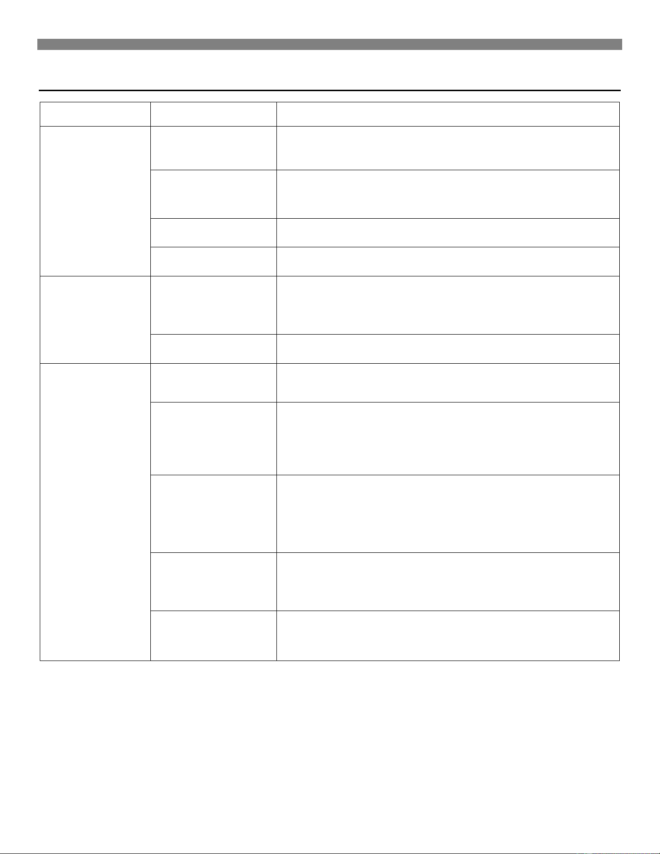
Troubleshooting
30
SYMPTOM POSSIBLE CAUSE CORRECTIVE ACTION
5. Heater operates,
but will not shut off
after room
temperature is
attained.
A. Thermostat wiring
defective.
Thermostat lead wires may be shorted together, caused by a nail or staple.
Check by removing thermostat leads from valve terminals.
B. Thermostat location.
Check thermostat location. If on an outside wall, or there is a hole in the wall
behind thermostat, cold air may be coming in contact with the thermostat.
Relocate the thermostat or plug the hole.
C. Defective thermostat. Verify thermostat temperature reading or replace.
D. Valve stuck open. Replace valve.
6. Pilot outage.
A. Pilot flame may be
too low or blowing
(high), causing pilot
to drop out.
Adjust pilot flame. Pilot orifice may be plugged
(Check for spider webs or other material).
B. Drafts or drafty areas. Check for doorway and high air movement areas.
7. Main burner will not
stay on.
A. Blockage in vent pipe. Checks vent pipe for blockage, such as bird nests, twigs, leaves, etc.
B. Thermostat location.
Check thermostat location - if on an outside wall or there is a hole in wall
behind the thermostat causing cold air to contact the thermostat, relocate the
thermostat or plug the hole.
Check that the vent cap is properly installed, and not placed too far down on
the vent pipe. Cap must be the same manufacturer as the vent.
C. Restriction in vent
system caused by
offsets.
All type "B" vents shall extend in a vertical direction with no more than two
offsets not exceeding 45 degrees. Any angle greater than 45 degrees from
vertical is considered
horizontal. Any offsets used should be as far above
the draft
hood as possible to allow venting to begin before any restriction is
encountered. The use of too many offsets may also prevent proper venting.
D. Incorrect vent pipe.
Use listed B/W type vent pipe. DO NOT use transite or any other type of
ceramic pipe for venting. DO NOT use single wall pipe. When venting into a
masonry chimney, the chimney must be properly lined and sized for this gas
heater. The use of type "B" or flexible chimney liner is recommended.
E. Loose connections on
the vent safety wiring
harness.
Check the connection on both the switch and the gas valve. Tighten if
necessary.
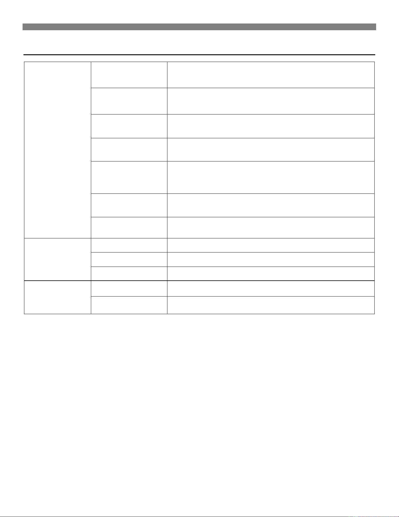
Troubleshooting
8. Abnormal
operation.
A. Delayed ignition - pilot
flame may be too low.
Adjust pilot flame. Refer to "How to Care for Your Heater" section in this
manual.
B. Expansion noise,
ticking.
Heater may be distorted by being vented through an uneven opening. A
restricted vent may create
expansion noise. Refer to "Venting" section of this
manual.
C. Combustible gas
spillage.
Check vent system for a blocked flue, excessive down draft (wind) or
negative pressure in room caused by ventilating fan or a fire in a fireplace.
D. Excessive flame roll-
out.
Heater is possibly overrated - check for high gas pressure at gas valve (see
4B).
E. Burner is over-fired.
Check the manifold gas pressure. Check the rate, this appliance is
manufactured for elevations up to 2,000 feet. It must be derated for
operation above 2,000 feet.
F. Yellow burner flame. Check burner for obstructions. Install new burner and pilot orifices.
G. Yellow pilot flame. Remove pilot orifice, check and clean.
9. Noisy blower.
A. Housing rattling. Tighten blower screws.
B. Blower dirty. Clean blower wheel.
C. Blower wheel bent.
Straighten or replace.
10. Blower does not
run.
A. Fan switch not set. Select fan speed.
B. Check bearings. Add oil as outlined in "Blower Accessory Instructions".
Hints and Information
32
Service Hints
If your heater fails to work correctly, you may avoid the
inconvenience and cost of a service call by checking the
troubleshooting section on pages 29 thru 31 before you call
for service
.
How to Order Repair Parts
When ordering repair parts, always give the following Information:
1. MODEL NUMBER
2. MFG. DATE CODE
3. PART NUMBER
4. PART DESCRIPTION
All parts listed herein may be ordered from your equipment
supplier. The Model Number of your Williams heater will be found
on the nameplate near the gas valve, inside the control
compartment.
WARNING:
If the information in this manual is
not followed exactly, a fire or explosion may
result causing property damage, personal
injury or loss of life.
Williams Furnace Company • 250 West Laurel Street, Colton, CA 92324
(909) 825-0993 • FAX: (909) 824-8009 • www.wfc-fc.com
Manufactured in the U.S.A. • Established 1916
DO NOT store or use gasoline or other
flammable vapors and liquids in the vicinity of
this or any other appliance.
WHAT TO DO IF YOU SMELL GAS
• Open all of the windows.
• Do not try to light any appliance.
• Do not touch any electrical switch.
• Do not use any phone or cell phone in
your building.
• Extinguish any open flame.
• Immediately call your gas supplier from
a neighbor’s phone. If you cannot reach
your gas supplier, call the fire
department.
Installation and service must be performed by
a qualified installer, service agency or the gas
supplier.
P500556 April 2015
ALL RIGHTS RESERVED