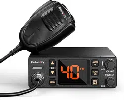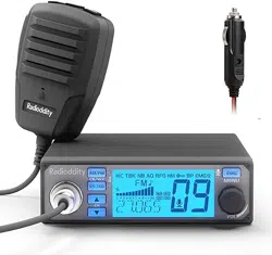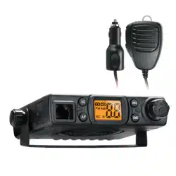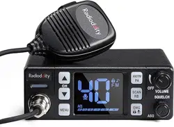
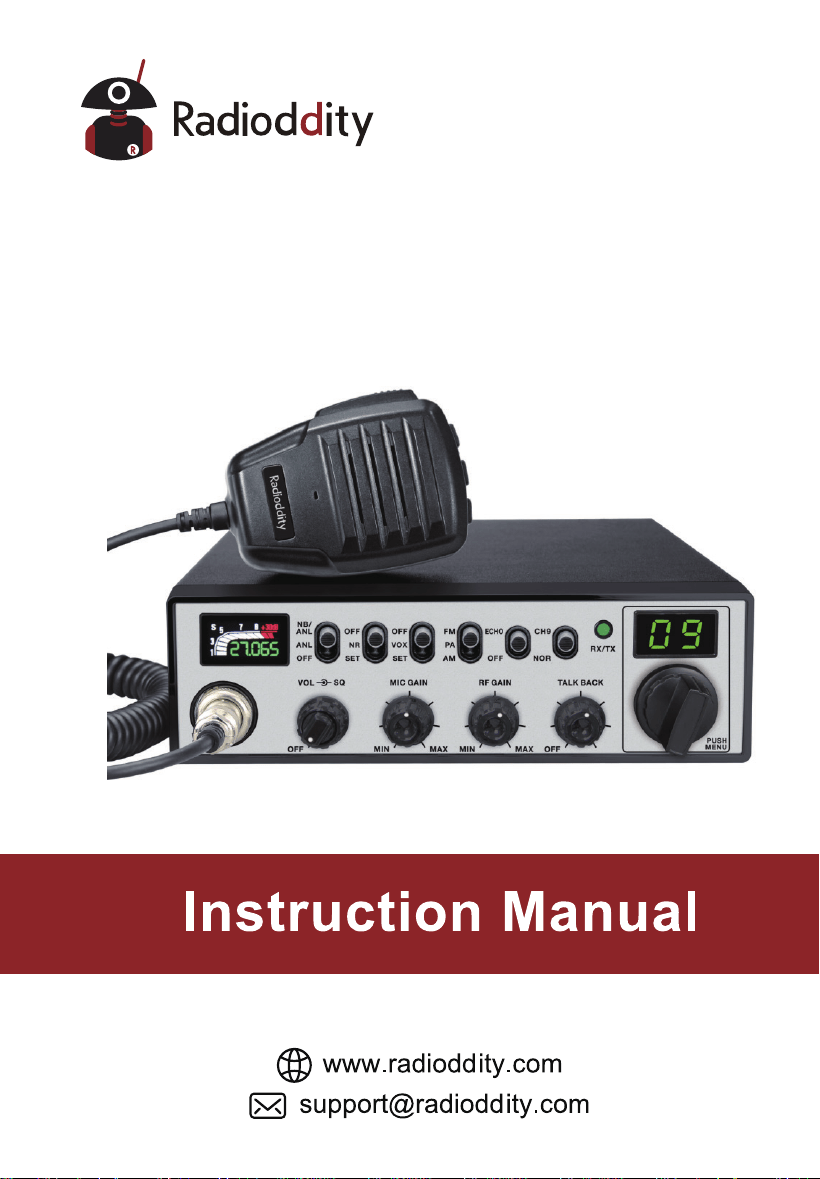
CB-900 PRO
CB RADIO

CONTENTS
1.STANDARD ACCESSORIES .............................................................1
2.
INSTALLATION ..................................................................................1
3.
GETTING ACQUAINTED ...................................................................5
4.
HOW TO USE YOUR RADIO ............................................................7
5.
SLIDE SWITCHES .............................................................................8
6.
FUNCTION MENU .............................................................................9
7.
SPECIFICATIONS ............................................................................11
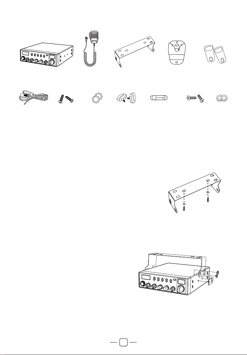
1
45"/%"3%"$$&4403*&4
Radio
Screws for
bracket
DC Power
Cable
Self-tapping
Screws
Microphone
Pads for
bracket
PadsAdjusting
screws
Microphone
Hanger
Mounting Bracket
Adhesive Case
Protectors
Spare Fuses
(3A,250V)
2*/45"--"5*0/
Choose the most appropriate loc
ation from a simple
and practical point of view. If installed in a vehicle, care
should be taken to ensure your radio does not obstruct
the driver or passengers.
1. Use the Self-tapping Screws and Pads to fix the
Bracket to a suitable location.
2. Attach the Adhesive Case Protectors to the inside ends of the Mounting Bracket
and insert the Radio. Fit the Adjusting Screws loosely, and choose a suitable angle
by moving the Adjusting Screws to one of the 3 positions on the Mounting Bracket.
3. Tighten the Adjusting Screws firmly by hand. Make sure the radio and all
accessories are securely mounted.
2
88
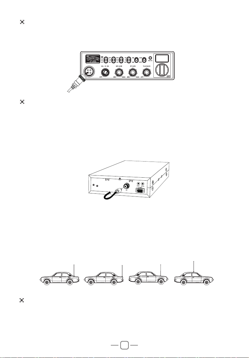
.*$301)0/&$0//&$5*0/
1. Plug microphone connector into the microphone jack.
2. Tighten the retaining ring on the microphone connector by hand.
ANTENNA INSTALLATION
POWER CONNECTION
Before using this radio, please install an efficient and resonant antenna. Using an
antenna that is correctly installed and tuned will enable excellent communication
performance.
This radio requires an antenna impedance of 50 ohms, unbalanced.
1. Screw the antenna connector into the antenna jack.
2. If required, grounding of the antenna system will ensure best performance.
This radio can operate at both 12 or 24 V voltage systems. A switching is not necessary.
3OHDVHUHIHUWRWKHUDGLR6SHFL¿FDWLRQVWRHQVXUH\RXU'&SRZHUVXSSO\FDQSURYLGH
enough current (amps), otherwise poor performance may occur.
WARNING:
Ÿ1(9(5WUDQVPLWZLWKRXWDFRQQHFWHGUHVRQDQWDQWHQQDRUDVXLWDEOHRKP
load being connected. Damage to the radio may result.
Ÿ7RUHGXFHWKHULVNRIHOHFWULFVKRFNRUUDGLRGDPDJHEDVHVWDWLRQLQVWDOODWLRQV
should include lightning protection devices.
Ÿ$VN\RXU5DGLRGGLW\GHDOHUIRUDYDLODEOHDQWHQQDRSWLRQV
3. A mobile antenna can be mounted in various locations, for example:
3
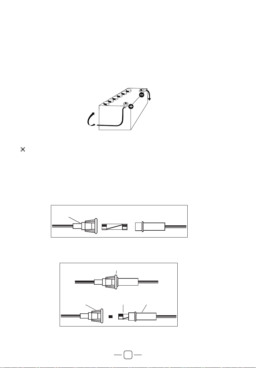
1. Connect the positive (red) power cable to the + terminal of the battery.
2. Connect the negative (black) power cable to the - terminal of the battery.
3. Connect the DC power cable to the transceiver's power supply connector.
Ÿ/RFDWHWKH SRZHUFDEOHDZD\ IURPKLJKWHPSHUDWXUH PRLVWXUHDQGRWKHU
electrical systems. Ensure it is installed where it cannot be damaged.
Ÿ,WLVQRWUHFRPPHQGHGWRXVHDYHKLFOHFLJDUFLJDUHWWHOLJKWHUVRFNHWWRSRZHUWKH
radio, as it may not supply the correct voltage or current.
Ÿ'RQRWUHPRYHWKHIXVHKROGHUIURPWKHFDEOH
REPLACING FUSES
This radio requires a 3A, 250V fuse.
If the fuse blows, determine the reason, then correct the problem.
After the problem is resolved, replace the fuse. If newly installed fuses continue
to blow, disconnect the power cable and contact your authorized dealer or an
authorized service center:
1. Twist the two fuse covers in opposite directions, and open it.
,
IN-LINE
FUSE HOLDER
2. Replace the blown fuse with new one, and close the fuse holder.
3. Be sure to only use the correct fuse type, otherwise damage may occur.
FUSE
IN-LINE
FUSE HOLDER
IN-LINE
FUSE HOLDER
IN-LINE
FUSE HOLDER
3A 250V FUSE
- (Black wire) connected
to chassis ground in most
vehicles (confirm with your
vehicle manufacturer)
+ (Red wire)
12V
4
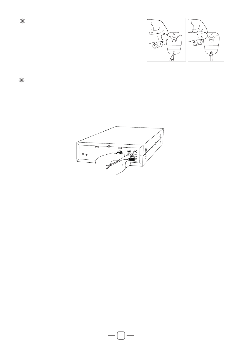
INSTALL EXTERNAL SPEAKER (Optional)
If using an external speaker, please choose an 8 ohm speaker with a 3.5mm mono
(double cable) TS type plug.
1. Install the external speaker in a suitable place.
2. Plug into the speaker jack.
INSTALL MICROPHONE HANGER
Choose a location which will not interfere with the
driver. Use the supplied self-tapping screws and
pads to install the hanger.
5
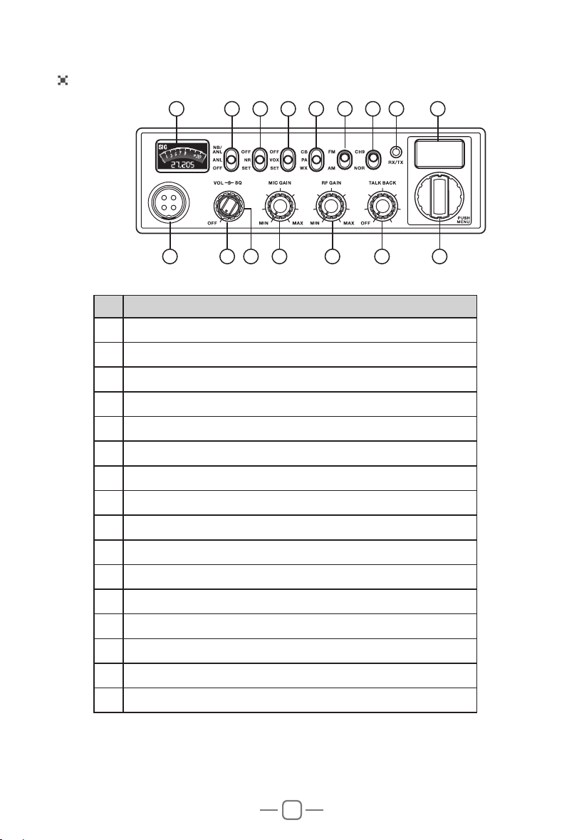
Front Panel
No. Functions
1 TFT LCD
2 1%$1/)XQFWLRQ2Q2II6ZLWFK
3 15)XQFWLRQ2Q2II156HWWWLQJ6ZLWFK
4 92;)XQFWLRQ2Q2II92;6HWWLQJ6ZLWFK
5 0RGH6ZLWFK&%3$:;
6 0RGXODWLRQ0RGH6ZLWFK)0$0
7 &KDQQHO1RUPDO6ZLWFK
8 5;5HFHLYH7;7UDQVPLW/(',QGLFDWRU
9 Channel Display: CH and Scrolling Frequency Display
10 4-Pin Microphone Connector
11 $XWRPDWLF6TXHOFK0DQXDO Squelch Control
12 3RZHU2Q2II9ROXPH&RQWURO
13 Microphone Gain Control
14 RF Gain Control
15 7DON%DFN2Q2II7DON%DFN9ROXPH/HYHO&RQWURO
16 &KDQQHO6HOHFWRU386+
9761 2 3 4 5
10 12 14 1513 1611
8
88
3. GETTING ACQUAINTED
6
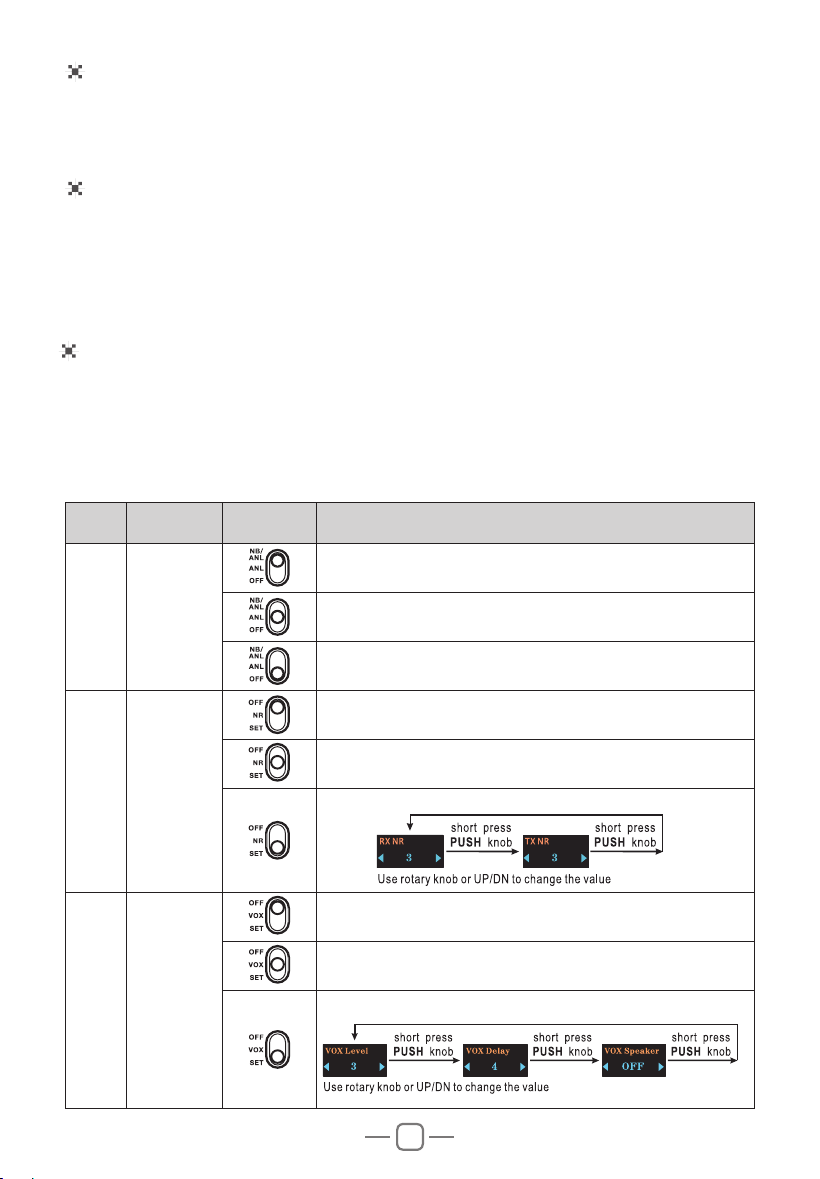
Microphone
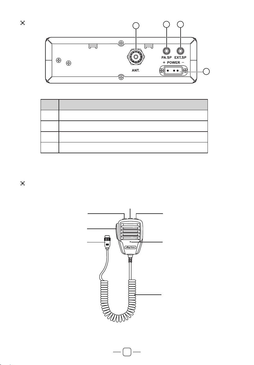
Rear Panel
No. Functions
17 Antenna Connector
18 Public Address Speaker Jack
19 External Speaker Jack
20 Power Jack
'2:1 UP
Microphone cable
Mic
PTT
Connector
PF
17
18
19
20

7
Manual Squelch Control (SQ)
RF Gain Control
Mic Gain Control
Turn the SQ knob clockwise to the exact point where all background noise disappear.
This adjustment should be done with precision as, if set to maximum (fully
clockwise), only the strongest signals will be received.
In RX, turn the RF GAIN knob to set the reception sensitivity. Clockwise to increase,
and anti-clockwise to decrease. Maximum position in the case of long-distance call
reception. You can decrease the RF GAIN, to avoid distortions, when the interlocutor
is near.
In POWER ON status, turn the MIG GAIN knob to adjust the Microphone Gain.
Clockwise to increase , and anti-clockwise to decrease.
Rotary "PUSH" Knob
In normal operation, turn rotary PUSH knob to change the channel. Clockwise to
increase, and anti-clockwise to decrease the channel.
Volume Control
Turn the VOL knob clockwise to increase the Volume, Turn it anti-clockwise to
decrease the Volume.
Note: Adjust the Volume during communication to obtain a suitable level.
Automatic Squelch Control (ASQ)
Turn the SQ knob anti-clockwise to the leftmost position enables the ASQ function.
"
DSSHDUVRQWKH/('1RUHSHWLWLYHPDQXDODGMXVWPHQWDQGDSHUPDQHQW
improvement between the sensitivity and the listening comfort when ASQ is active.
This function can be disconnected by turning the switch clockwise. In this case the
squelch adjustment becomes manual.
TALK BACK
This function allows you to hear your own modulation in the optional internal or
external speaker connected to the EXT.SP jack.
Turn the TALK BACK knob anti-clockwise to the leftmost position disable the TALK
BACK function.
Turn the TALK BACKNQREWRLQFUHDVHFORFNZLVHGHFUHDVHDQWLFORFNZLVHWKH
volume level of the TALK BACK.
4.HOW TO USE YOUR RADIO
Power OFF/ON
1. Turn the VOLNQREFORFNZLVHWRVZLWFKWKHUDGLR21WKHUDGLRPD\HPLWDEHHSLI
the beep function is enabled). The LED display will show a channel number.
2. Turn the VOL knob anti-clockwise, until hear Ka Ta, the radio is powered off.
8
UP / DN Buttons On Microphone
In normal operation, press UP / DN buttons on the microphone to change the
channel. UP to increase, and DN to decrease the channel.
,Q0(18PRGH SUHVVWKHPUSH knob for about 3 seconds to activate this mode),
the UP or DN buttons allows to select the mune to be set.
SCAN
Press and hold UP or DN buttons on the microphone for 7 seconds or until a beep
sounds activate the 40 channels scan function. The scanning stops as soon as there
is a busy channel.
In scanning mode, turn rotary PUSH knob on the unit or press UP or DN buttons on
the microphone to change scan direction.
Press PTT button to exit channels scan.
PF Buttons On Microphone
Press PFEXWWRQRQWKHPLFURSKRQHWRVHOHFWWKHIHDWXUHWREHGLVSOD\HGLQ7;/&'
DOWHUQDWHVZLWKWKHHPLWWHGSRZHUOHYHORU6WDQGLQJ:DYH5DWLR6:5
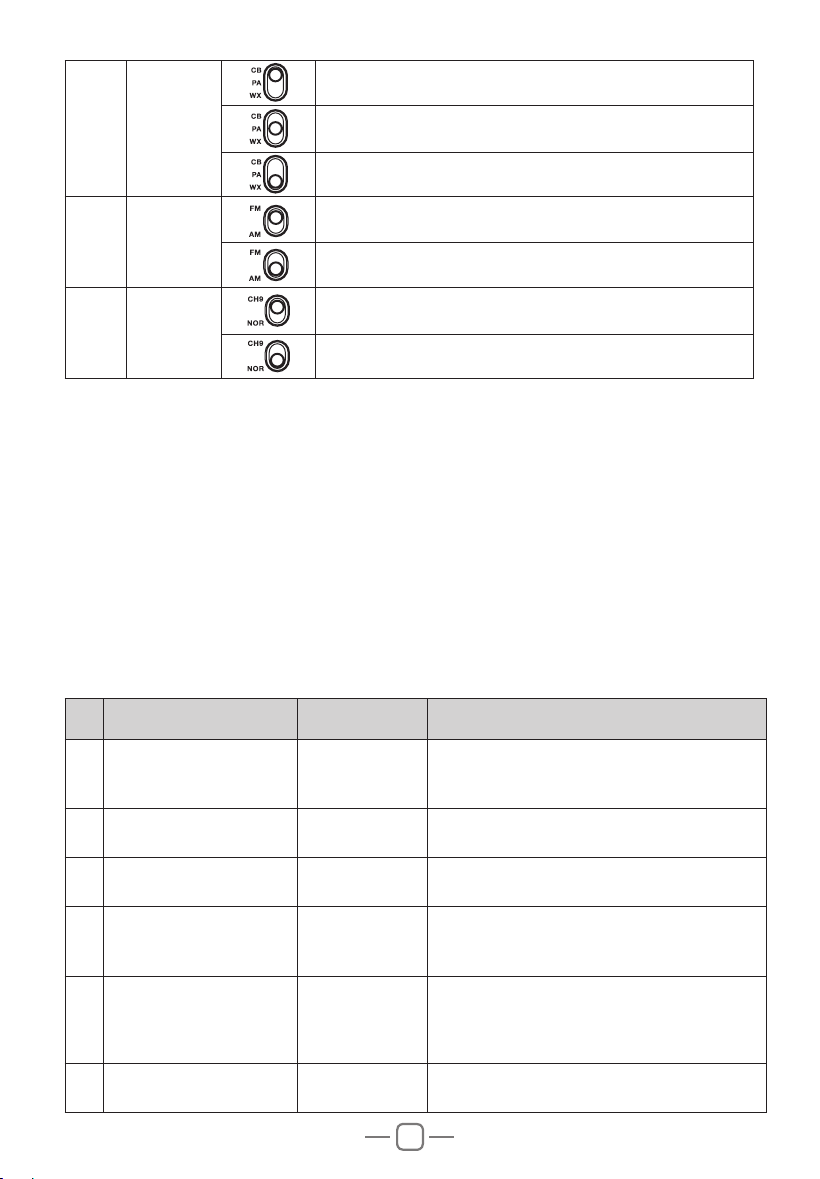
5. SLIDE SWITCHES
No. Function Position Description
1
1%$1/
¿OWHUV
7XUQRQ1%$1/IXQFWLRQ
7XUQRQ$1/IXQFWLRQ
7XUQRII1%$1/IXQFWLRQ
2
1RLVH
Reduction
15
7XUQRII15IXQFWLRQ
7XUQRQ15IXQFWLRQ
15SDUDPHWHUVVHWWLQJ
3 92;
7XUQRII92;IXQFWLRQ
7XUQRQ92;IXQFWLRQ
92;SDUDPHWHUVVHWWLQJ
9
6. FUNCTION MENU
No.
'VODUJPO -$%%JTQMBZ %FTDSJQUJPO
1
Beep sound setting
Key Beep
ON
: turn on beep sound
OFF
: turn off beep sound
Default :
ON
2
Roger beep sound
setting
Roger Beep
OFF
(default),
1
~
6
OFF:
turn off RB sound function.
3
Backlight brightness
setting
Dimmer
Bright
(default)
Dimmed
4
Signal strengt meter type
setting
Display Type
S-Meter
Bargraph
Classic
(default)
5
Select the feature to be
GLVSOD\HGLQ7;
Display Mode
RF
(default)
SWR
NOTE:Use the PF button on the microphone
for quick selection.
6
Microphone type setting
Mic Type
Electret
(default)
Dynamic
1. Press and hold the PUSH knob to enter menu.
2. Turn the rotary PUSH knob or press the UP / DN buttons on the microphone to
select the menu.
3. Press the PUSH knob to validate. The parameter of the chosen function blinks on
the display.
4. Turn the rotary PUSH knob or press the UP / DN buttons on the microphone to
modify the value of the parameter.
5. 1HZSUHVVPUSH knob to validate the chosen value. The parameter stops blinking.
6. ,IQRNH\LVSUHVVHGWKH XQLWH[LWV0(18 DIWHUVHQFRQGV Press and hold the
PUSHNQRERUSUHVV377EXWWRQWRYDOLGDWHVWKHODVWVHWWLQJDQGH[LVWV0(18
4 Mode
Select the CB mode
Select the Public Address (PA) mode
6HOHFWWKH:;PRGH
5
Modulation
Mode
Select the Frequency Modulation (FM) mode
Select the Amplitude Modulation (AM) mode
6
Instant
Channel
To access Instant channel 9
Return to the original channel selected

10
7
Scan type setting
Scan Type
Squelch
(default)
Time
8
(&+2IXQFWLRQVHWWLQJ
ECHO
ON
: turn on (&+2IXQFWLRQ
OFF
: turn off (&+2IXQFWLRQ(default)
9
(&+2YROXPHOHYHO
setting
ECHO Volume
1
~
32
Default :
28
10
(&+2GHOD\WLPHVHWWLQJ
ECHO Delay
1
~
32
Default :
28
11
ALERT function setting
WX Alert
ON
: turn on ALERT function
OFF
: turn off ALERT function (default)
12
Time out timer
Time Out Timer
OFF
,
1Min
~
10Min
Default :
3Min
13
6:5ZDUQLQJVHWWLQJ
SWR Warning
OFF
,
2:1
~
10:1
Default :
2:1
This function can set the threshold for antenna
ZDUQLQJ:KHQ LWLVGHWHFWHGWKDW WKH6:5RI\RXU
antenna system exceeds the set threshold, the emitted
red indicator light will flash and the LCD will display
6:5+,WRDOHUWV\RXWRWURXEOHLQWKHDQWHQQDV\VWHP
14
3$5;SDWKVHWWLQJ
PA-RX Path
PA
(default):
The modulation of the microphone and the received
signal are transmitted to the PA loudspeaker
connected to jack PA.SP.
IN/EXT
:
The modulation of the microphone is transmitted
to the PA loudspeaker connected to jack PA.SP;
the received signal is transmitted to the internal
loudspeaker (or external optional loudspeaker
connected to jack EXT.SP).
OFF
:
The reception is no more functional. Only the
modulation of the microphone is transmitted to the PA
loudspeaker connected to jack PA.SP.
15
ASQ function setting
ASQ
ON : turn on ASQ function
OFF : turn off ASQ function
Default : ON
Resume Factory Default
Press and hold the PUSH knob to enter menu.
Turn the rotary PUSH knob or press the UP / DN buttons on the microphone to select
the
Reset
function.
Press the PUSH knob to validate. The option blinks on the display (
YES
or
NO
).
Turn the rotary PUSH knob or press the UP / DN buttons on the microphone to select
the option.
NO
: stop reset operation.
YES
: continue reset operation.
Press the PUSHNQREWRFRQ¿UPWKHXQLWDXWRPDWLFDOO\UHVHWHG
11
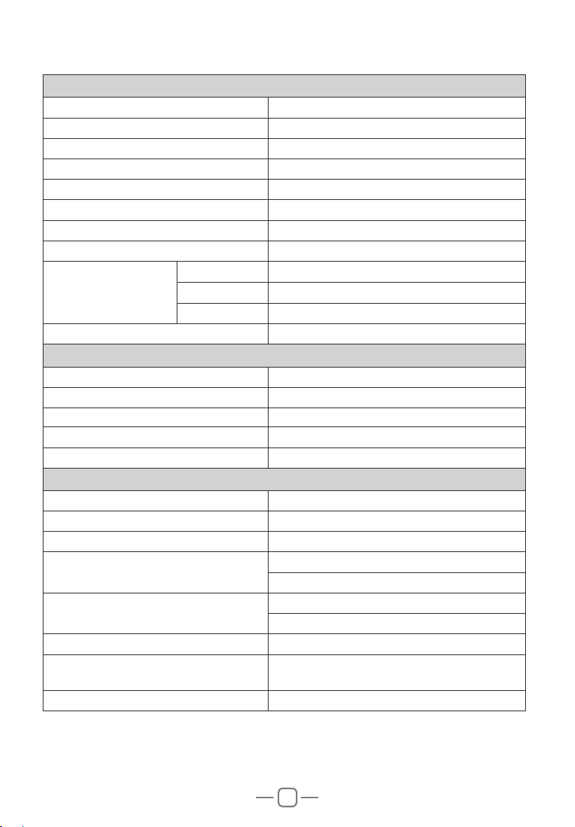
1RWH6SHFLILFDWLRQVDUHVXEMHFWWRFKDQJHZLWKRXWQRWLFHGXHWR DGYDQFHPHQWVLQ
technology.
GENERAL
Modulation Mode $0)0
Frequency Range 26.965-27.405MHz
:HDWKHU&KDQQOHV 162.400-162.550MHz
Frequency Tolerance ±5.0ppm
Input Voltage 9
Dimensions /[:[+PP
:HLJKW 1.02kg
2SHUDWLQJ7HPSHUDWXUH5DQJH -20
ą
to +50
ą
Current Drain
Transmit $0$;
Receive Squelched 0.3A
92/0D[ 0.7A
Antenna Connector 8+)62
TRANSMITTER
3RZHU2XWSXW :DWWV)0$0
Transmission interference LQIHULRUWRQ:
Frequency Response 300-3000Hz
Modulated signal distortion inferior to 5%
2XWSXW,PSHGDQFH 50 ohms
RECEIVER
Sensitivity /HVVWKDQX9IRUG%611
Image Rejection 70dB
Adjacent Channel Rejection 60dB
IF Frequencies
1st 10.695MHz
2nd 455KHz
Automatic Gain Control(AGC)
Less than 10dB change in audio
2XWSXWIRULQSXWVIURPWRX9
Squelch less than 1uV
$XGLR2XWSXW3RZHU :DWWVDWȍOHVVWKDQGLVWRUWLRQ
Frequency Response 300-3000Hz
7.
SPECIFICATION