
Po w e r Pr u n e r
TM
oP e r a T o r 's Ma n u a l
1
Power Pruner
TM
Operator's Manual
MODEL PPF-225
WARNING
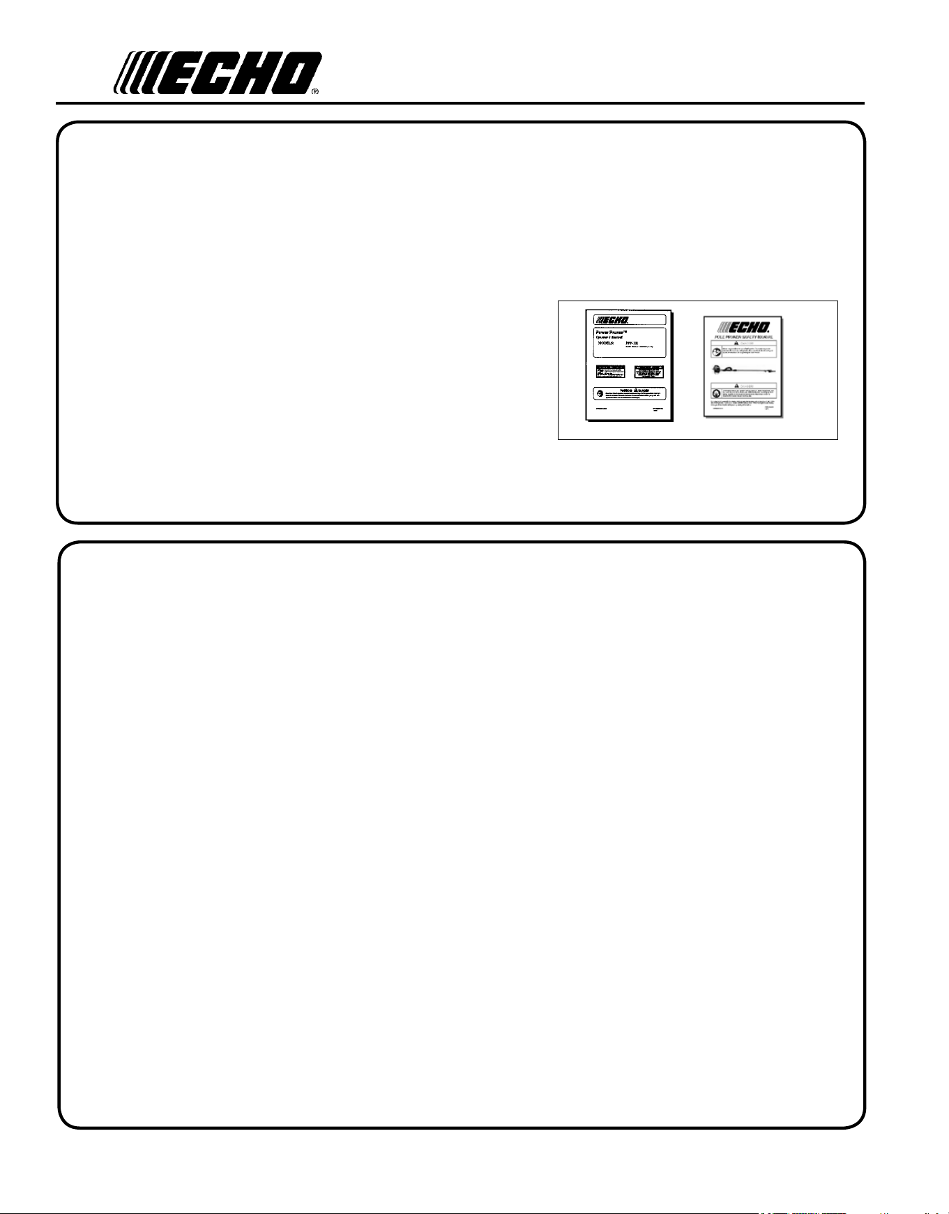
Read rules for safe operation and instructions carefully. ECHO provides an Operator's
Manual and a Safety Manual. Both must be read and understood for proper and safe
operation. Failure to do so could result in serous injury.
X750011893
12/09
X7502308103
2
Copyright© 2010 By Echo, Incorporated
All Rights Reserved.
In t r o d u c t I o n
Welcome to the ECHO family. This ECHO product was designed and manufactured to provide long life and on-the-job
dependability. Read and understand this manual and the SAFETY MANUAL you found in the same package. You will
nd both easy to use and full of helpful operating tips and SAFETY messages.
t h e o p e r a t o r 's m a n u a l
Read and understand this manual before operation. Keep it in a safe
place for future reference. It contains specications and information
for operation, starting, stopping, maintenance, storage, and assembly
specic to this product.
t h e s a f e t y m a n u a l
Read and understand this manual before operation. Keep it in a safe
place for future reference. It explains possible hazards involved with
the use of Power Pruner
TM
and what measures you should take to make
their use safer.
ta b l e o f co n t e n t s
Introduction ................................................................2
- The Operator's Manual ........................................2
- The Safety Manual ..............................................2
Safety .........................................................................3
- Manual Safety Symbols and Important
Information ......................................................... 3
- International Symbols .........................................3
- Personal Condition and Safety Equipment .........4
- Kickback .............................................................6
- Equipment ...........................................................7
Emission Control .......................................................8
Description .................................................................8
Contents ................................................................... 11
Assembly.................................................................. 11
- Cutting Attachment to Drive Shaft Installation 11
- Saw Chain Tension Adjustment ........................ 12
Operation ..................................................................13
- Fuel ...................................................................13
- Lubricating the Guide Bar and Saw Chain .......15
- Adjusting Automatic Oiler ................................15
- Starting Cold Engine .........................................16
- Starting Warm Engine .......................................17
- Stopping Engine ................................................17
- Pruning Techniques ...........................................18
Maintenance .............................................................19
- Skill Levels .......................................................19
- Maintenance Intervals ....................................... 19
- Air Filter ...........................................................20
- Fuel Filter ..........................................................20
- Spark Plug .........................................................21
- Cooling System Cleaning ................................. 21
- Exhaust System .................................................22
- Carburetor Adjustment ......................................24
- High Altitude Operation .................................24
- Guide Bar and Saw Chain Replacement ........... 25
- Filing Saw Chain ..............................................28
Troubleshooting .......................................................29
Storage .....................................................................30
Specications ........................................................... 31
Warranty Statements ................................................32
Servicing Information .............................................. 36
- Parts/Serial Number .......................................... 36
- Service ..............................................................36
- ECHO Consumer Product Support ...................36
- Warranty Card ...................................................36
- Additional or Replacement Manuals ................36
Specications, descriptions and illustrative material
in this literature are as accurate as known at the time
of publication, but are subject to change without
notice. Illustrations may include optional equipment
and accessories, and may not include all standard
equipment.
Po w e r Pr u n e r
TM
oP e r a T o r 's Ma n u a l
3
sa f e t y
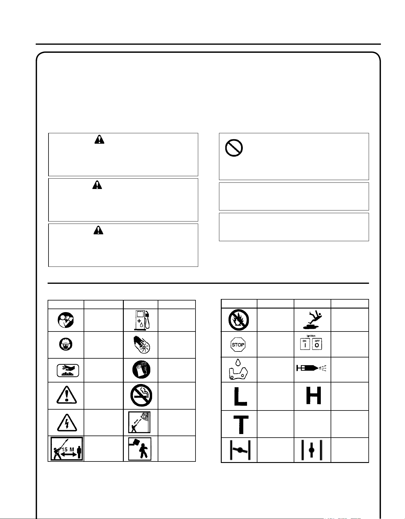
ma n u a l sa f e t y sy m b o l s a n d Im p o r t a n t In f o r m a t I o n
Hot
Surface
Symbol
description/application
Symbol form/shape
Symbol
description/application
Symbol form/shape
Read and understand
Operator's Manual.
Wear eyes, ears and
head protection
Fuel and oil mixture
Finger Severing
Safety/Alert
Avoid all power lines.
This unit is not insu-
lated against electri-
cal current.
Do not operate closer
than 15 M (50 ft.) from
electrical haz-
ards.
Keep bystanders
at least 15 meters
(50 feet) away.
Plan retreat
path from falling
objects.
Wear hand
protection. Use
two handed.
DO NOT smOke
Near fuel.
I n t e r n a t I o n a l s y m b o l s
Symbol
description/application
Symbol form/shape
Symbol
description/application
Symbol form/shape
Carburetor adjustment
- Idle speed
Carburetor adjustment
- High speed mixture
Emergency stop
Carburetor adjustment
- Low speed mixture
DO NOT ALLOW
FLAMES OR
SPARKS NEAR
FUEL.
Wear slip resistant
foot wear.
Ignition
ON/OFF
ChaiN lubriCa-
TiON
Primer bulb
Choke Control
"Cold Start"
Position
(Choke Closed)
Choke Control
"Run"
Position
(Choke Open)
WARNING
The safety alert symbol accompanied by the word
“WARNING” calls attention to an act or condi-
tion which CAN lead to serious personal injury or
death if not avoided.
CIRCLE AND sLAsh syMbOL
This symbol means the specic action
shown is prohibited. Ignoring these prohi-
bitions can result in serious or fatal injury.
CAUTION
The safety alert symbol accompanied by the word
“CAUTION” calls attention to an act or condition
which may lead to minor or moderate personal
injury if not avoided.
NOTE
This enclosed message provides tips for use, care and
maintenance of the unit.
IMPORTANT
The enclosed message provides information neces-
sary for the protection of the unit.
DANGER
The safety alert symbol accompanied by the word
“DANGER” calls attention to an act or condition
which WILL lead to serious personal injury or
death if not avoided.
Throughout this manual and on the product itself, you will nd safety alerts and helpful, informational messages pre-
ceded by symbols or key words. The following is an explanation of those symbols and key words and what they mean to
you.
4
Physical Condition
Your judgment and physical dexterity may not be good:
• if you are tired or sick,
• if you are taking medication,
• if you have taken alcohol or drugs.
Operate unit only if you are physically and mentally well.
Eye Protection
Wear eye protection that meets ANSI Z87.1 or CE re-
quirements whenever you operate the unit
Face and Head Protection
When trimming overhead, always wear head protection
meeting ANSI Z89.1 or CE requirements with a full face
shield. Head protection with full face shield will help
protect you from falling branches and debris.
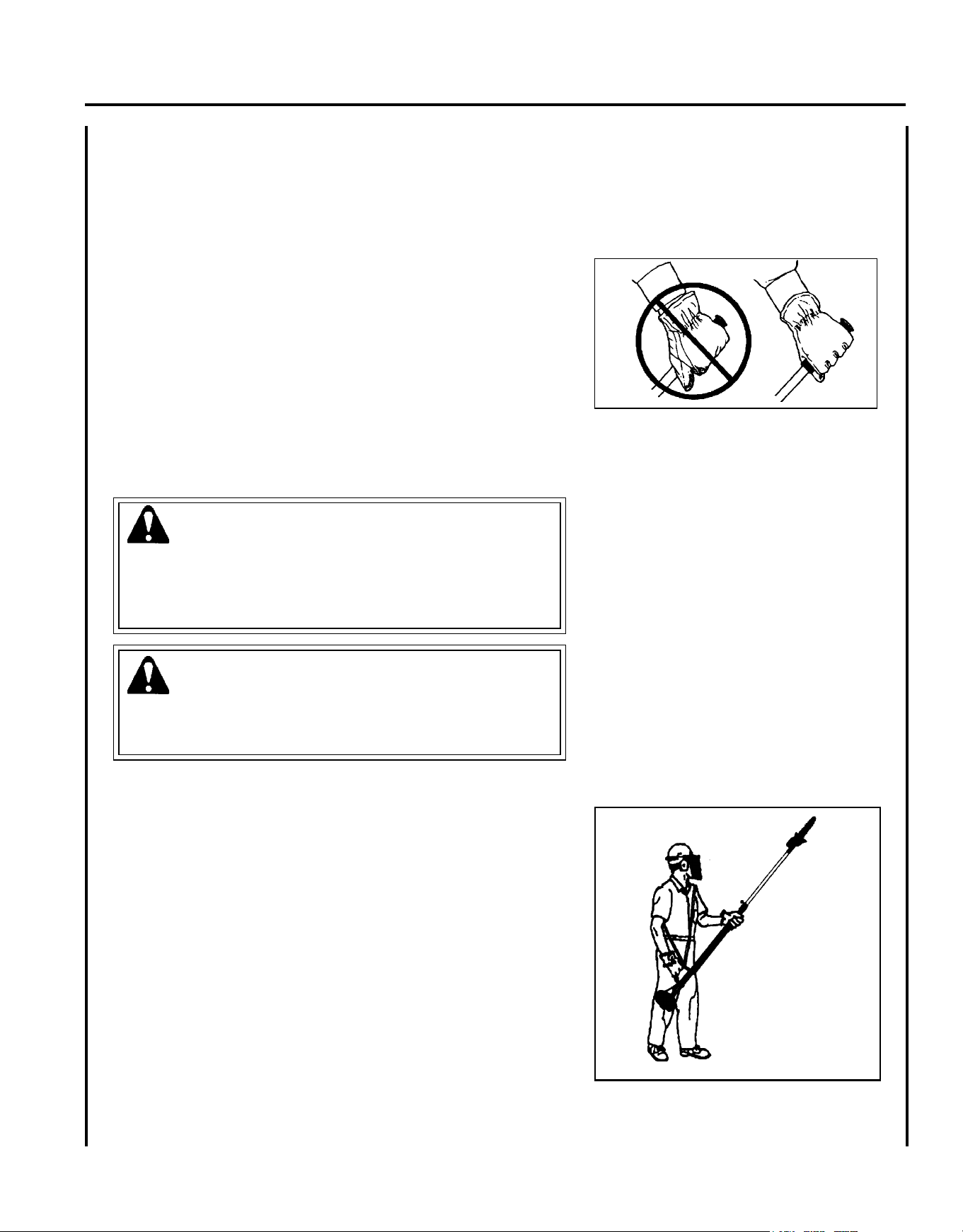
Hand Protection
Wear no-slip, heavy duty work gloves to improve your
grip on the unit handles. Gloves also reduce the transmis-
sion of machine vibration to your hands.
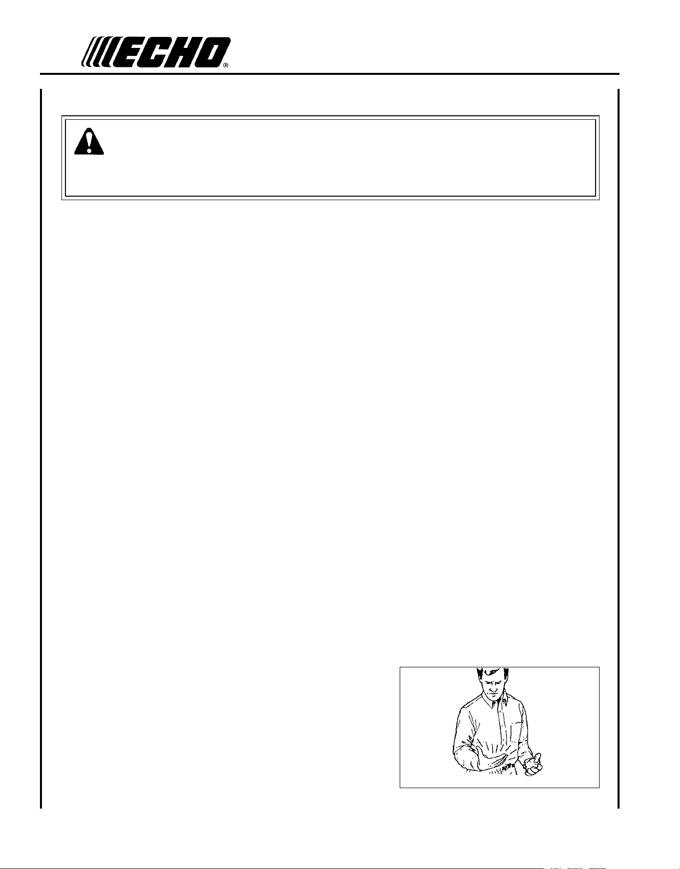
Vibration and Cold
It is believed that a condition called Raynaud’s Phenomenon, which affects the ngers of certain individuals may be
brought about by exposure to vibration and cold. Exposure to vibration and cold may cause tingling and burning sen-
sations followed by loss of color and numbness in the ngers. The following precautions are strongly recommended
because the minimum exposure which might trigger the ailment is unknown.
• Keep your body warm, especially the head, neck, feet, ankles, hands
and wrists.
• Maintain good blood circulation by performing vigorous arm
exercises during frequent work breaks and also by not smoking.
• Limit the hours of operation. Try to ll each day with jobs where
operating the unit or other hand-held power equipment is not
required.
• If you experience discomfort, redness, and swelling of the ngers
followed by whitening and loss of feeling, consult your physician
before further exposing yourself to cold and vibration.
p e r s o n a l c o n d I t I o n and s a f e t y e q u I p m e n t
WARNING
Power Pruner
TM
users risk injury to themselves and others if the Power Pruner
TM
is used improperly and or safety
precautions are not followed. Proper clothing and safety gear must be worn when operating a Power Pruner
TM
.
Hearing Protection
ECHO recommends wearing hearing protection whenever
unit is used.
Proper Clothing
Wear snug tting, durable protective clothing; chain saw
safety pants or chaps are recommended.
• Pants should have long legs, shirts with long sleeves.
• DO NOT WEAR SHORTS,
• DO NOT WEAR TIES, SCARVES, JEWELRY.
Wear sturdy protective safety shoes or boots with non-
skid soles;
• DO NOT WEAR OPEN TOED SHOES,
• DO NOT OPERATE UNIT BAREFOOTED.
Keep long hair away from engine and air intake. Retain
hair with cap or net.
Hot Humid Weather
Heavy protective clothing can increase operator fatigue,
which may lead to heat stroke. Schedule heavy work for
early morning or late afternoon hours when temperatures
are cooler.
Po w e r Pr u n e r
TM
oP e r a T o r 's Ma n u a l
5
DANGER
All over head electrical conductors and communications wires can
have electricity ow with high voltages. This unit is not insulated
against electrical current. Never touch wires directly or indirectly
when pruning, otherwise serious injury or death may result.
WARNING
Do not operate this product indoors or in inadequately ventilated
areas. Engine exhaust contains poisonous emissions and can cause
serious injury or death.
Read the Manuals
• Provide all operators of this equipment with the Operator's Manual,
and instructions for safe operation.
Clear the Work Area
• Spectators and fellow workers must be warned, and children and
animals prevented from coming nearer than 15 m (50 ft.) while the
unit is in use.
Use Proper Clothing & Equipment
• Always wear head protection with full face shield to help protect
against falling branches and debris.
Keep A Firm Grip
• Grip Power Pruner
TM
with both hands with thumbs and ngers encir-
cling the handle, and shaft tube.
Repetitive Stress Injuries
It is believed that overusing the muscles and tendons of the ngers, hands, arms and shoulders may cause soreness,
swelling, numbness, weakness and extreme pain in those areas. Certain repetitive hand activities may put you at a high
risk for developing a Repetitive Stress Injury (RSI). An extreme RSI condition is Carpal Tunnel Syndrome (CTS), which
could occur when your wrist swells and squeezes a vital nerve that runs through the area. Some believe that prolonged
exposure to vibration may contribute to CTS. CTS can cause severe pain for months or even years.
To reduce the risk of RSI/CTS, do the following:
• Avoid using your wrist in a bent, extended or twisted position. In-
stead try to maintain a straight wrist position. Also, when grasping,
use your whole hand, not just the thumb and index nger.
• Take periodic breaks to minimize repetition and rest your hands.
• Reduce the speed and force with which you do the repetitive move-
ment.
• Do exercises to strengthen the hand and arm muscles.
• Immediately stop using all power equipment and consult a doctor if
you feel tingling, numbness or pain in the ngers, hands, wrists or
arms. The sooner RSI/CTS is diagnosed, the more likely permanent
nerve and muscle damage can be prevented.
6
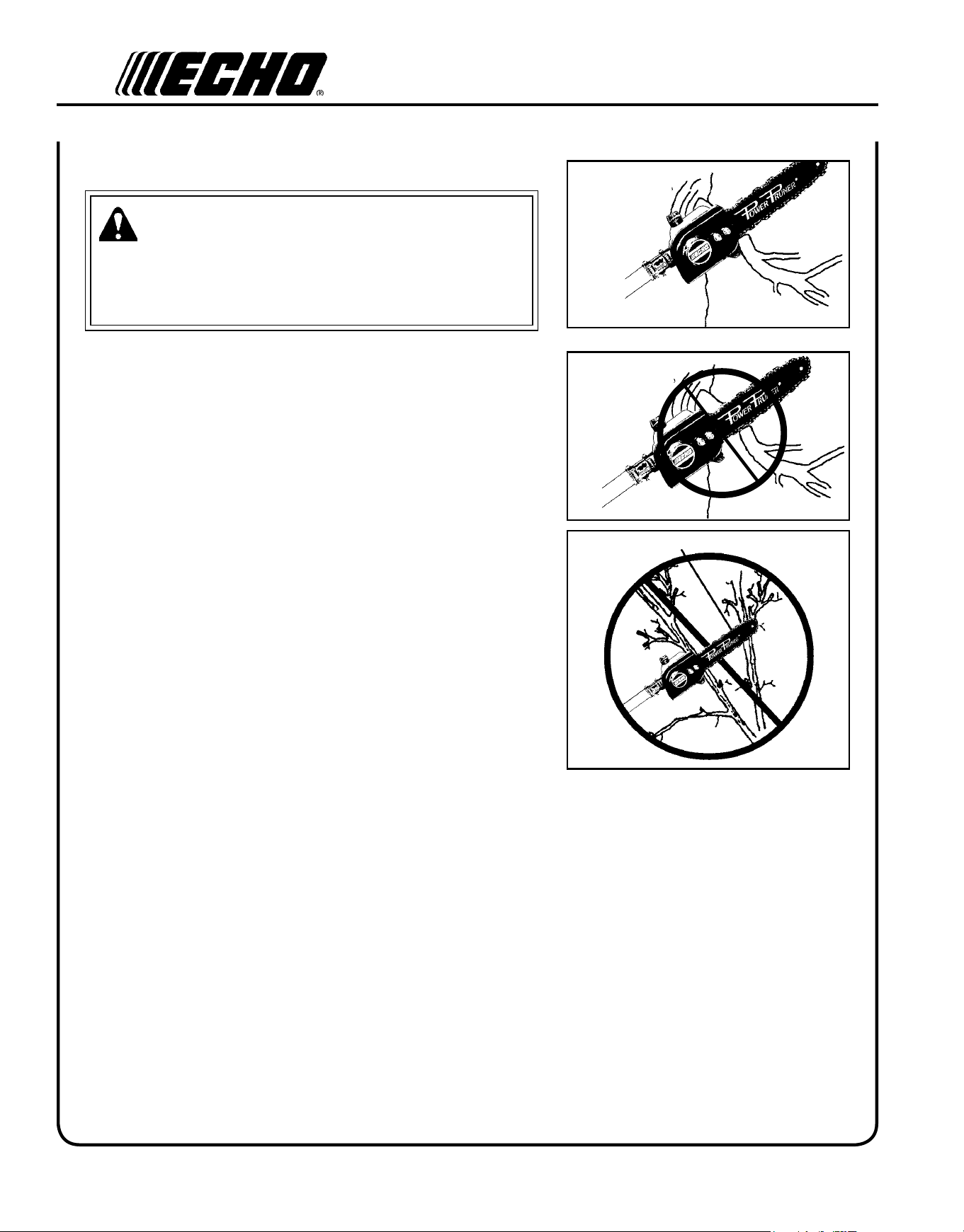
WARNING
Kickback can lead to dangerous loss of control of the Power Pruner
TM
and result in serious injury to the operator
or any one standing close by. Hold the Power Pruner
TM
rmly with both hands with thumbs and ngers encircling
the front and rear handles. Be aware of the down and outward path the pruner will take after the cut is made.
Keep A solid stance
• Maintain footing and balance at all times. Do not stand on slippery,
uneven or unstable surfaces. Do not work in odd positions or on
ladders. Do not overreach.
• Operate the Power Pruner
TM
only from the ground or out of an ap-
proved bucket lift.
• Always evaluate the branches to be pruned for hazards such as loose
dead branches which may fall and strike the operator or helpers.
Remove hazards before pruning.
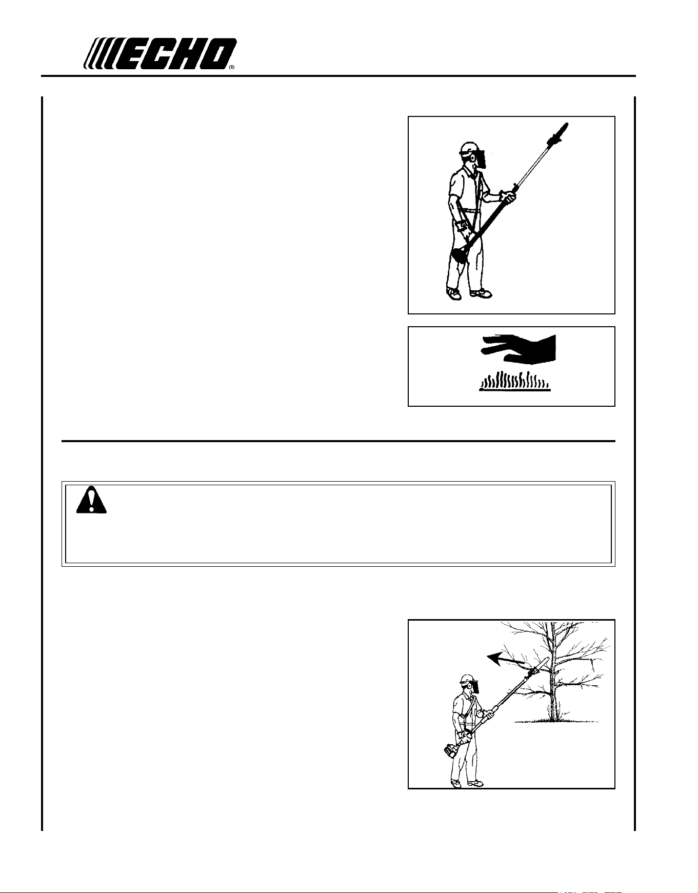
• Plan retreat path from falling objects.
• Cut branches bounce when striking ground.
• Check that shoulder harness is adjusted for safe, comfortable opera-
tion. See picture at right for proper adjustment.
• Turn the Power Pruner
TM
off when moving from tree to tree.
• Avoid any contact with saw chain.
Avoid hot surfaces
• Keep exhaust area clear of ammable debris. Avoid contact during
and immediately after operation.
k I c k b a c k
Kickback may occur when the moving saw chain at the nose or tip of
the guide bar touches an object, or when the wood closes in and pinches
the saw chain in the cut. In some cases this may cause a lightning-fast
reverse action, kicking the guide bar and saw chain up and back or
down and back towards the operator. Either of these reactions may
cause the operator to lose control of the Power Pruner
TM
which could
result in serious personal injury.
With a basic understanding of kickback, you can reduce or eliminate
the element of surprise which contributes to accidents.
Avoid contact of the guide bar tip with any object while the saw chain
is moving.
Cut only wood. Avoid striking concrete, metal, wire, or other obstruc-
tions which could cause kickback or damage to the saw chain.
If the saw chain does strike a foreign object, immediately stop the en-
gine, inspect and repair the Power Pruner
TM
if necessary.
Po w e r Pr u n e r
TM
oP e r a T o r 's Ma n u a l
7
e q u I p m e n t
WARNING
Serious injury may result from the use of non approved guide bar and saw chain combinations. ECHO, INC. will not
be responsible for the failure of cutting devices or accessories which have not been tested and approved by ECHO
for use with this unit. Read and comply with all safety instructions listed in this manual.
• Check unit for loose/missing nuts, bolts, and screws. Tighten and/or replace as needed.
Guide Bar and Saw Chain
• Check that the cutting attachment, guide bar, and saw chain is rmly attached and in safe operating condition.
• Use only one Echo-approved extension on the pruner.
• Do not hit rocks, stones, tree stumps, and other foreign objects with the saw chain.
• Do not cut into the ground with the saw chain.
• If cutting attachment end strikes an obstruction, stop engine immediately and inspect saw chain for damage.
• Do not operate with a dull, fractured, or discolored saw chain.
• Remove all foreign objects from work area.
• Always cover the guide bar and saw chain with guide bar cover during transportation and for storage.
WARNING
Moving parts can amputate ngers or cause severe injuries. Keep hands, clothing and loose objects away from all
openings.
• ALWAys stop engine, disconnect spark plug, and make sure all moving parts have come to a complete stop
before removing obstructions, clearing debris, or servicing unit.
• DO NOT start or operate unit unless all guards and protective covers are properly assembled to unit.
• NEVER reach into any opening while the engine is running. Moving parts may not be visible through openings.
WARNING
Check fuel system for leaks due to fuel tank damage, especially if the unit is dropped. If damage or leaks are found,
do not use unit, otherwise serious personal injury or property damage may occur. Have unit repaired by an autho-
rized servicing dealer before using.
8
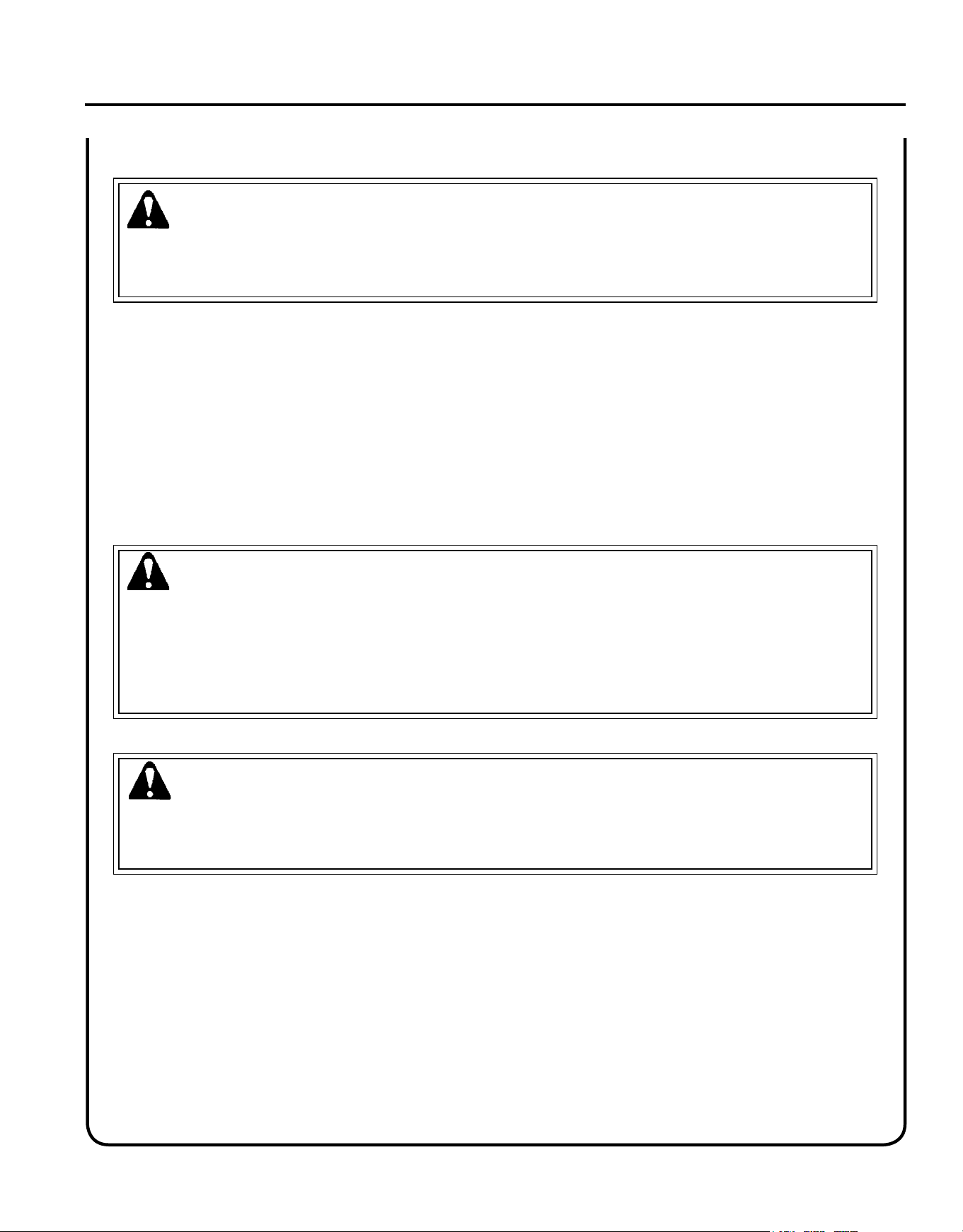
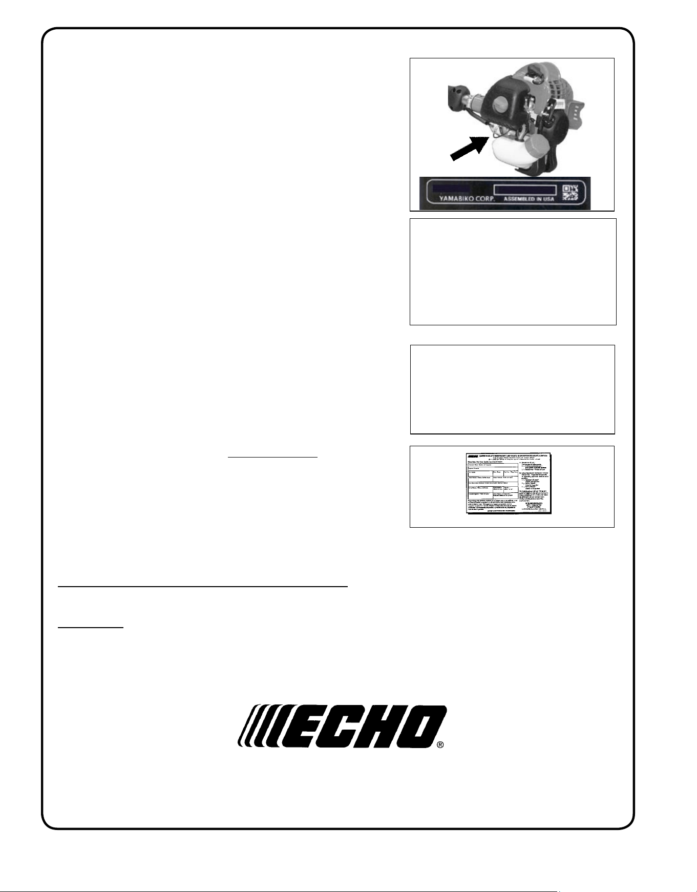
An Emission Control Label is located on the engine. (This is an EXAMPLE ONLY, information on label varies by
engine FAMILY).
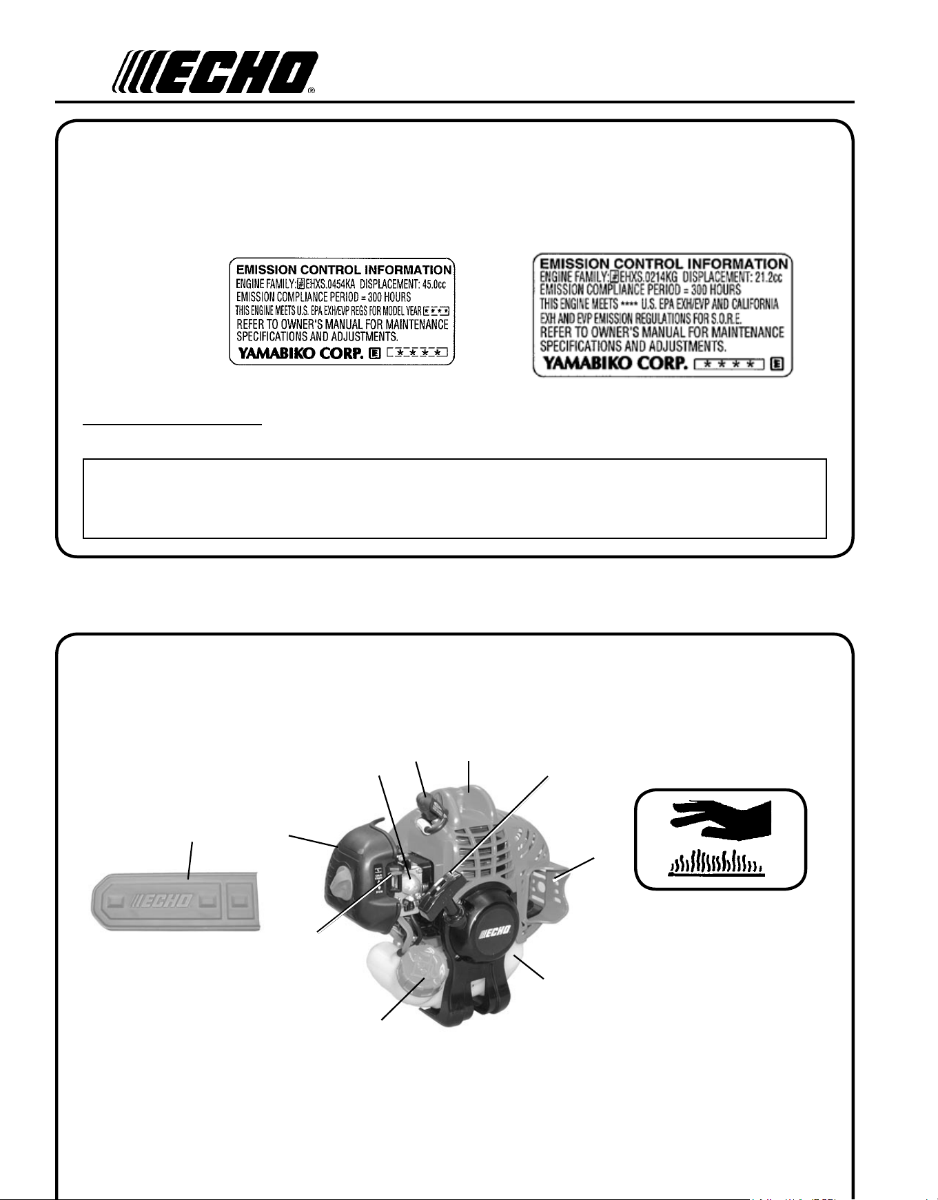
de s c r I p t I o n
Locate this safety decal on your unit. Make sure the decals are legible and that you understand and follow the instruc-
tions on them. If a decal cannot be read, a new one can be ordered from your ECHO dealer. See PARTS ORDERING
instructions for specic information.
P/N X505002310
Hot Decal (near mufer)
23
14
22
15
16
17
20
18
19
21
PRODUCT EMIssION DURAbILITy (EMIssION COMPLIANCE PERIOD)
The 300 hour emission compliance period is the time span selected by the manufacturer certifying the engine emis-
sions output meets applicable emissions regulations, provided that approved maintenance procedures are followed as
listed in the Maintenance Section of this manual.
em I s s I o n co n t r o l (e X h a u s t & e v a p o r a t I v e )
EPA 2010 and Later and/or C.A.R.B. TIER III
The emission control system for the engine is EM/TWC (Engine Modication and 3-way Catalyst) and for the fuel tank
the Control System is EVAP (Evaporative Emissions) or N (for nylon tank). Evaporative emission may be applicable to
California models only.
Po w e r Pr u n e r
TM
oP e r a T o r 's Ma n u a l
9
1
2
8
7
3
4
5
6
9
10
11
12
P/N X505001821
13
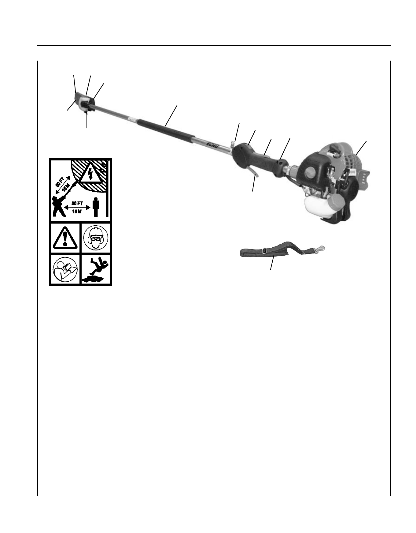
1. POWER hEAD - Includes the Engine, Clutch, Fuel System, Ignition System and Starter.
2. REAR hANDLE AssEMbLy - Rear (right hand) handle.
3. ThROTTLE TRIGGER LOCKOUT - This lever must be held during starting. Operation of the throttle trigger is
prevented unless throttle trigger lockout lever is engaged.
4. sTOP sWITCh - Mounted on top of rear handle assembly. Move switch forward to run, back to stop.
5. sTRAP hOOK - Used to secure unit to shoulder harness.
6. FRONT hANDLE - Cushioned grip for left hand.
7. CUTTING ATTAChMENT - Sealed, gear ratio is 1.5:1 reduction.
8. AUTOMATIC OILER AssEMbLy - Self oiling. Use high quality, low viscosity, non detergent bar and chain oil.
9. GUIDE bAR - 254 mm (10 inch) Bar.
10. sAW ChAIN - 91, 9.53mm (3/8 inch) pitch, 0.050 gauge low prole Oregon® saw chain. Runs approximately
609.6 m/min. (2000 ft/min) at full throttle.
11. CUTTING shOE - Used to capture and stabilize branch while cutting. Place cutting shoe against branch, acceler-
ate and lower saw chain into branch.

10
12. ThROTTLE TRIGGER - Spring loaded to return to idle when released. During acceleration press throttle trigger
gradually for best operating technique.
13. shOULDER hARNEss - An adjustable strap that suspends the unit from the operator.
14. RECOIL sTARTER hANDLE - Pull handle slowly until recoil starter engages, then quickly and rmly. When
engine starts return handle slowly. DO NOT let handle snap back or damage will occur.
15.
sPARK ARREsTOR MUFFLER OR sPARK ARREsTOR MUFFLER WITh CATALysT -The mufer or
catalytic mufer controls exhaust noise and emission. The spark arrestor screen prevents hot, glowing particles of
carbon from leaving the mufer. Keep exhaust area clear of ammable debris.
16. FUEL TANK - Contains fuel and fuel lter.
17. FUEL TANK CAP - Covers and seals fuel tank opening.
18. ChOKE - Located above air cleaner housing. Move lever to starting position (
) (close choke) and back to run
position (
) (open choke).
19. AIR CLEANER AssEMbLy - Contains replaceable air lter element.
20. PURGE bULb - Pumping purge bulb before starting engine draws fresh fuel from the fuel tank, purging air from
the carburetor. Pump purge bulb until fuel is visible and ows freely in the clear fuel tank return line. Pump purge
bulb an additional 4 or 5 times.
21. sPARK PLUG - Provides spark to ignite fuel mixture.
22. TOP GUARD - Protects arm from hot engine.
23. GUIDE bAR COVER - Used to cover guide bar and saw chain during transport and storage. Remove guide bar
cover before using unit.
Po w e r Pr u n e r
TM
oP e r a T o r 's Ma n u a l
11
co n t e n t s
Due to packaging restriction the ECHO product you have purchased requires some assembly.
After opening the carton, check for damage. Immediately notify your retailer or ECHO Dealer of damaged or missing
parts. Use the contents list to check for missing parts.
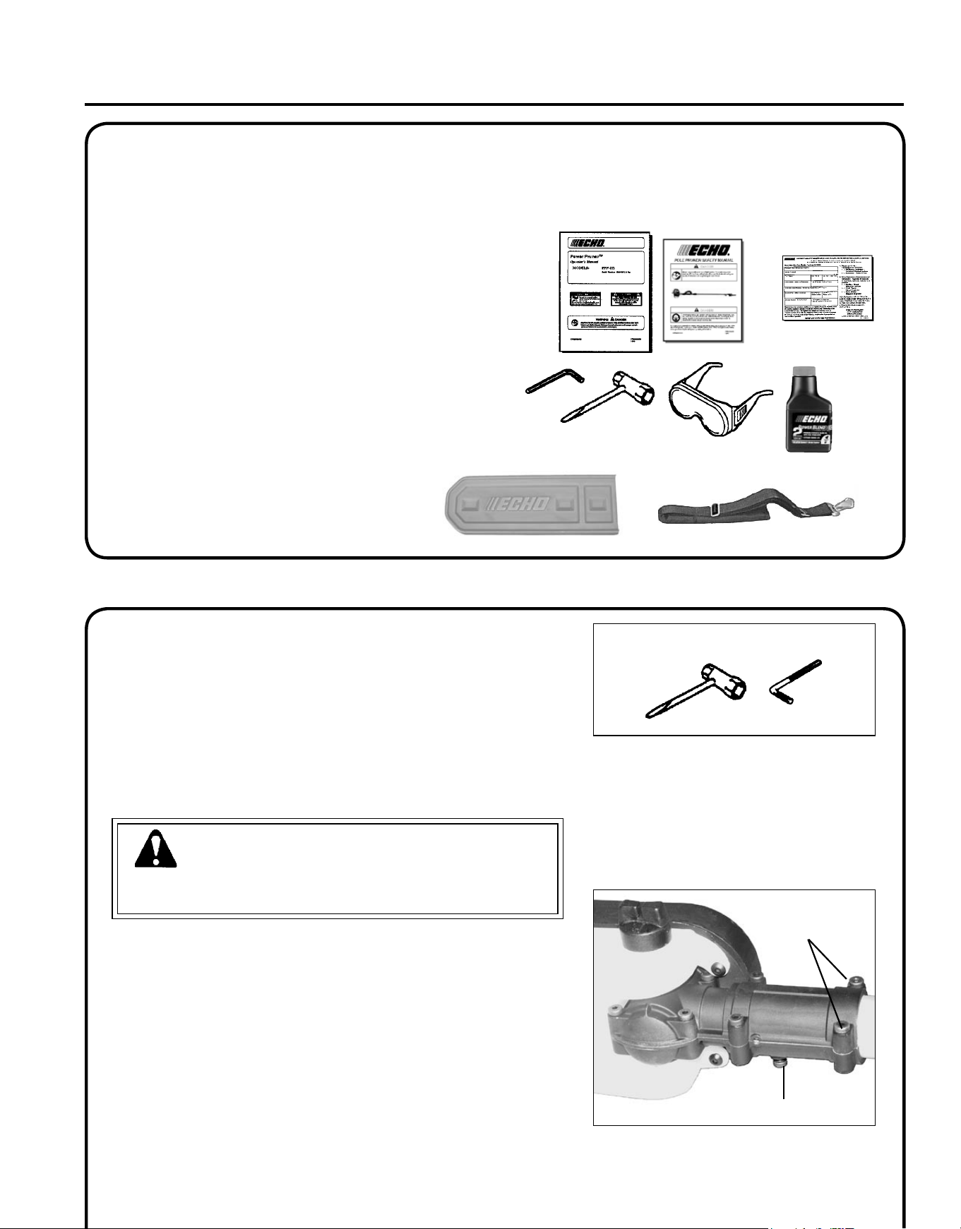
___ Power Head/Drive Shaft Assembly
___ Cutting Attachment
___ Operator's Manual
___ Safety Manual
___ Warranty Registration Card
___ 1, T-Wrench (Combination screwdriver/spark plug socket)
___ 1, T27 Torx L-Wrench
___ Safety Glasses
___ Echo Power BlendX
TM
2-stroke oil sample
___ Shoulder Harness
___ Guide Bar Cover
as s e m b l y
Tools Required: T-wrench, T27 Torx L-Wrench
Parts Required: Drive Shaft Assembly, Cutting Attachment
WARNING
Saw Chain is sharp! Always wear gloves when handling assembly,
otherwise serious personal injury may result.
1. Loosen the two (2) screws (A) and remove locator screw (B) on
cutting attachment.
c u t t I n g a t t a c h m e n t t o d r I v e s h a f t I n s t a l l a t I o n
b
a
12
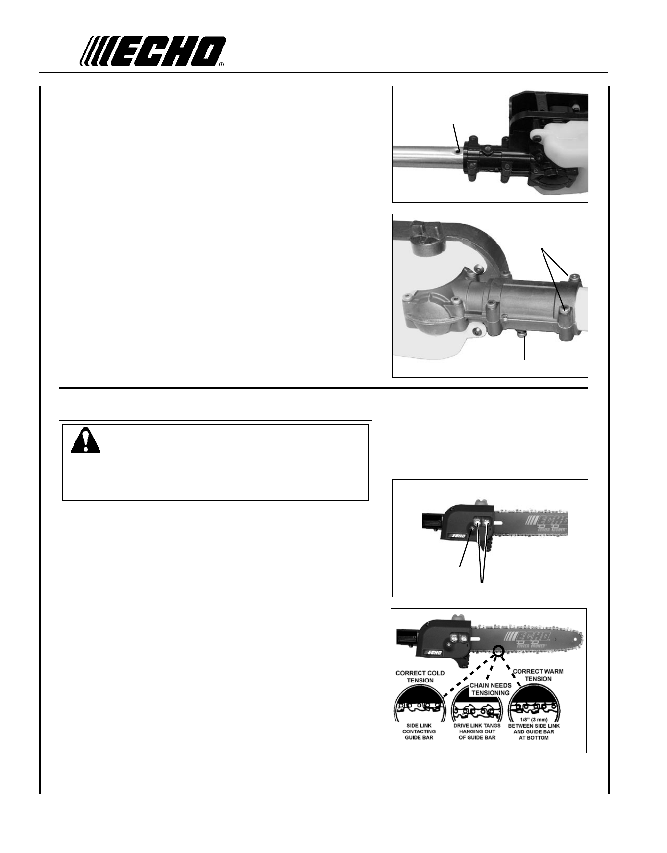
2. Slide the cutting attachment onto the shaft housing until the hole
in the neck of the cutting attachment is aligned with the hole (C) in
the housing. (It may be necessary to rotate the saw chain slightly
to align the internal pinion and drive shaft.)
3. Insert locator screw (B) into hole (C) and tighten to snug.
4. Tighten bolts (A), clamping the cutting attachment onto the hous-
ing.
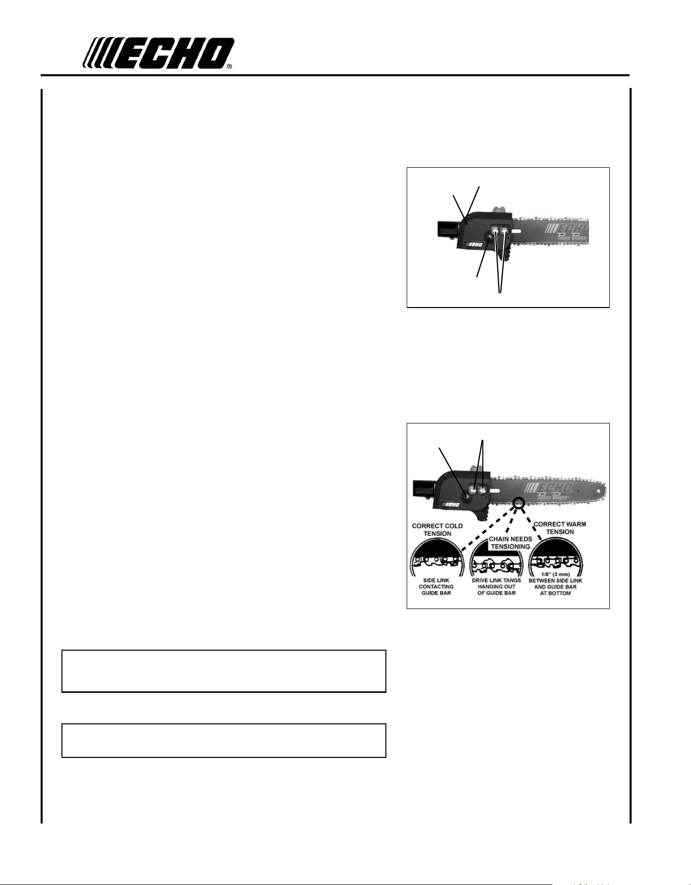
s a w c h a I n t e n s I o n a d j u s t m e n t
WARNING
Always disconnect spark plug wire before servicing cutting attach-
ment. Wear gloves when handling saw chain, otherwise serious
personal injury may result.
To Adjust Saw Chain Tension
1. Move stop switch to STOP position.
2. Disconnect spark plug lead.
3. Loosen two guide bar nuts (A) until nger tight.
4. Hold the bar nose up, and turn the adjuster screw (B) clockwise un-
til the chain ts snugly against the underside of the bar, as shown.
Cold Chain Only - turn adjuster screw CW an additional 1/8 - 1/4
turn.
5. Tighten both guide bar nuts with nose held up. Tighten rear nut
rst.
6. Pull the chain around the guide bar by hand. Reduce the chain ten-
sion if you feel tight spots.
7. When chain is properly tensioned, tighten guide bar nuts securely.
A
B
b
c
a
Po w e r Pr u n e r
TM
oP e r a T o r 's Ma n u a l
13
IMPORTANT
Tighten guide bar nuts to 8 - 9 N•m (71 - 80 in. lbs.) DO NOT
over-tighten nuts. Damage may result.
8. Keep chain properly tensioned at all times.
NOTE
All chains require frequent adjustment.
9. Connect spark plug lead.
f u e l
NOTICE: Use of unmixed, improperly mixed, or fuel older than 90 days, (stale fuel), may cause hard starting, poor
performance, or severe engine damage and void the product warranty. Read and follow instructions in the Storage
section of this manual.
WARNING
Alternative fuels, such as E-15 (15% ethanol), E-85 (85% ethanol) or any fuels not meeting ECHO requirements are
NOT approved for use in ECHO 2-stroke gasoline engines. Use of alternative fuels may cause performance prob-
lems, loss of power, overheating, fuel vapor lock, and unintended machine operation, including, but not limited to,
improper clutch engagement. Alternative fuels may also cause premature deterioration of fuel lines, gaskets, carbure-
tors and other engine components.
Fuel Requirements
Gasoline - Use 89 Octane [R+M/2] (mid grade or higher) gasoline known to be good quality. Gasoline may contain up to
10% Ethanol (grain alcohol) or 15% MTBE (methyl tertiary-butyl ether). Gasoline containing methanol (wood alcohol)
is NOT approved.
op e r a t I o n
WARNING
Moving parts can amputate ngers or cause severe injuries. Keep hands, clothing and loose objects away from all
openings. Always stop engine, disconnect spark plug, and make sure all moving parts have come to a complete
stop before removing obstructions, clearing debris, or servicing unit.
WARNING
Operation of this equipment may create sparks that can start res around dry vegetation. This unit is equipped
with a spark arrestor and a spark arrestor may be required. The operator should contact local re agencies for
laws or regulations relating to re prevention requirements.
14
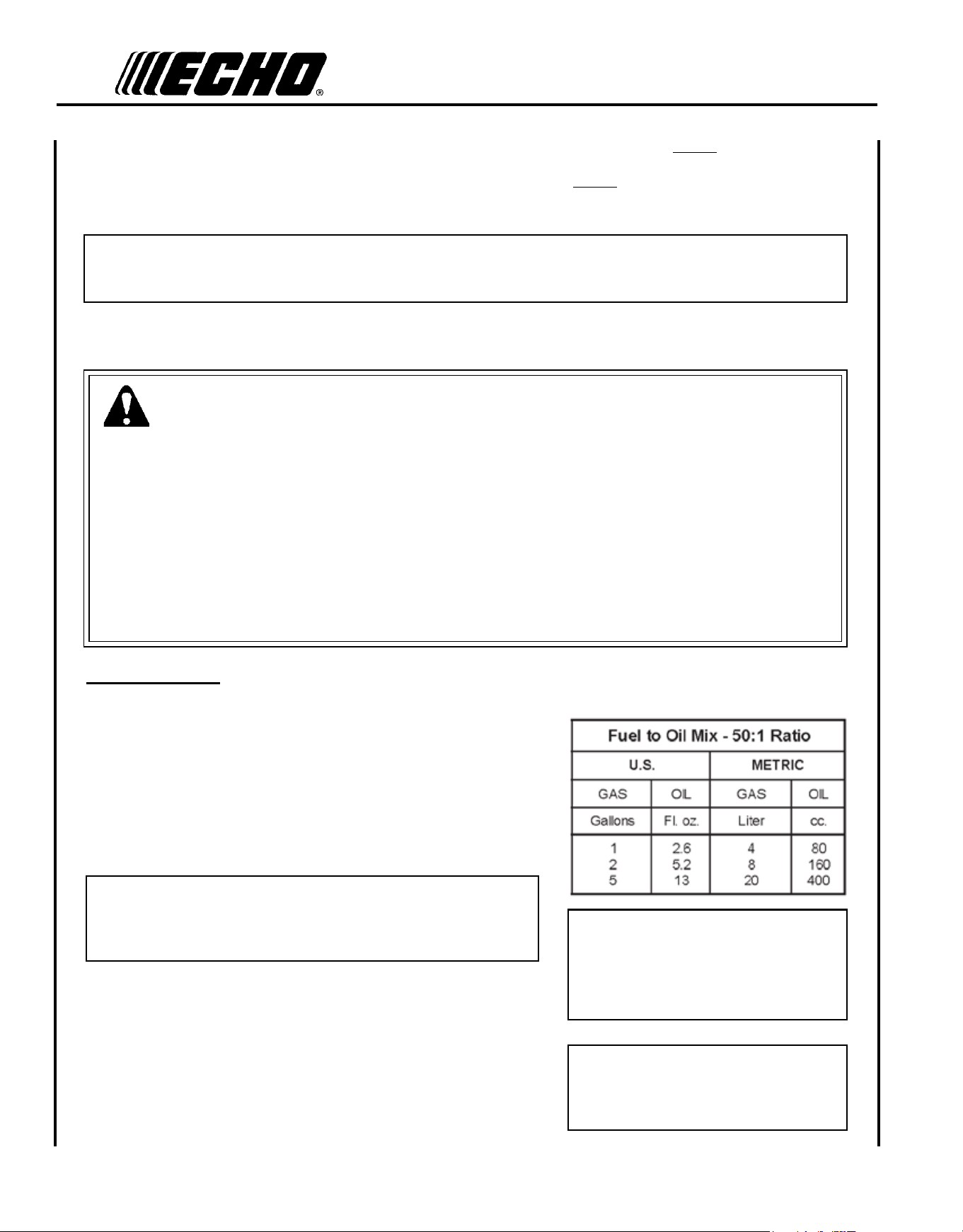
Mixing Instructions
1. Fill an approved fuel container with half of the required amount of
gasoline.
2. Add the proper amount of 2-stroke oil to gasoline.
3. Close container and shake to mix oil with gasoline.
4. Add remaining gasoline, close fuel container, and remix.
IMPORTANT
Spilled fuel is a leading cause of hydrocarbon emissions. Some
states may require the use of automatic fuel shut-off containers
to reduce fuel spillage.
After use
• DO NOT store a unit with fuel in its tank. Leaks can occur. Return
unused fuel to an approved fuel storage container.
storage - Fuel storage laws vary by locality. Contact your local gov-
ernment for the laws affecting your area. As a precaution, store fuel in
an approved, airtight container. Store in a well-ventilated, unoccupied
building, away from sparks and ames.
DANGER
Fuel is VERY ammable. Use extreme care when mixing, storing or handling or serious personal injury may result.
• Use an approved fuel container.
• DO NOT smoke near fuel.
• DO NOT allow ames or sparks near fuel.
• Fuel tanks/cans may be under pressure. Always loosen fuel caps slowly allowing pressure to equalize.
• NEVER refuel a unit when the engine is HOT or RUNNING!
• DO NOT ll fuel tanks indoors. ALWAYS ll fuel tanks outdoors over bare ground.
• DO NOT overll fuel tank. Wipe up spills immediately.
• Securely tighten fuel tank cap and close fuel container after refueling.
• Inspect for fuel leakage. If fuel leakage is found, do not start or operate unit until leakage is repaired.
• Move at least 3m (10 ft.) from refueling location before starting the engine.
Handling Fuel
IMPORTANT
Stored fuel ages. Do not mix more
fuel than you expect to use in thirty
(30) days, ninety (90) days when a
fuel stabilizer is added.
IMPORTANT
Stored two-stroke fuel may separate.
ALWAYS shake fuel container thor-
oughly before each use.
Two stroke Oil - A two-stroke engine oil meeting ISO-L-EGD (ISO/CD 13738) and J.A.S.O. FC/FD Standards must be
used. Echo brand premium Power Blend X
TM
Universal 2-Stroke Oil meets these standards. Engine problems due to in-
adequate lubrication caused by failure to use an (ISO/CD 13738) and J.A.S.O. FC/FDcertied oil, such as Echo premium
Power Blend X
TM
, will void the two-stroke engine warranty.
IMPORTANT
Echo premium Power Blend X
TM
Universal 2-Stroke Oil may be mixed at 50:1 ratio for application in all Echo en-
gines sold in the past regardless of ratio specied in those manuals.
Po w e r Pr u n e r
TM
oP e r a T o r 's Ma n u a l
15
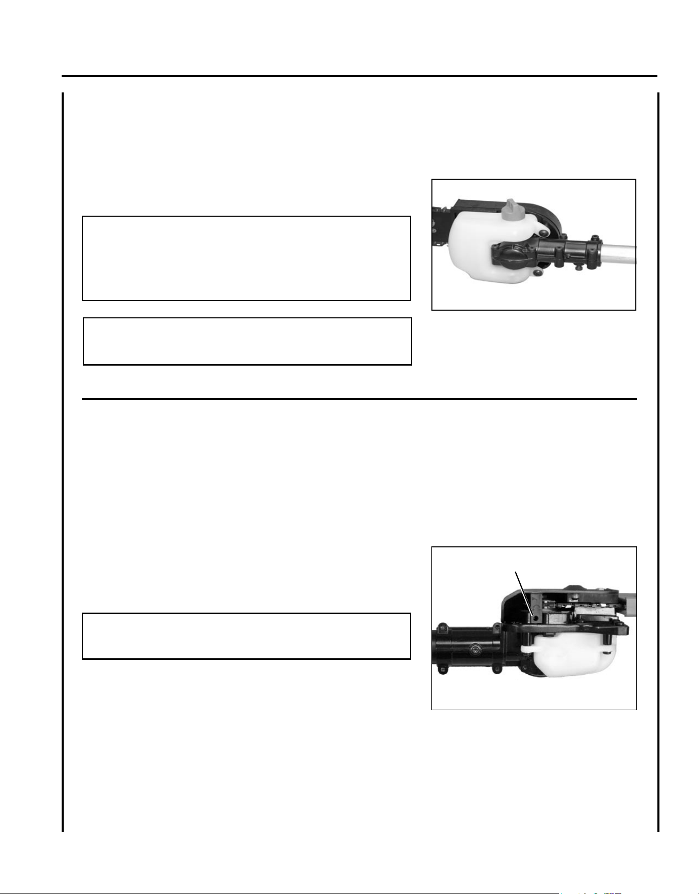
1. Wipe debris from around oil ll cap.
2. Remove oil ll cap and ll reservoir with a quality, low viscosity
guide bar and saw chain oil.
NOTE
The discharge volume of the automatic oiler is preset to deliver 3
to 4 cc/min. at normal operating RPM. During heavy or dry cutting
conditions the oil discharge volume may be adjusted to assure ad-
equate lubrication. Rell the oil reservoir with each tank of fuel.
IMPORTANT
To prevent plastic deterioration, do not use synthetic or silicone
based oil.
a d j u s t I n g a u t o m a t I c o I l e r
Tools required: Screwdriver
1. From bottom of gear case, turn adjustment screw (A) clockwise to
decrease oil volume - counter clockwise to increase oil volume.
NOTE
Very little visible oil on the saw chain will provide sufcient lubri-
cation.
l u b r I c a t I n g t h e g u I d e b a r a n d s a w c h a I n
Automatic Oiling System
A
16
s t a r t I n g c o l d e n g I n e
WARNING
The attachment will operate immediately when the engine starts
and could result in loss of control and possible serious injury. Keep
movable parts of the attachment off the ground and away from
objects that could become entangled or thrown.
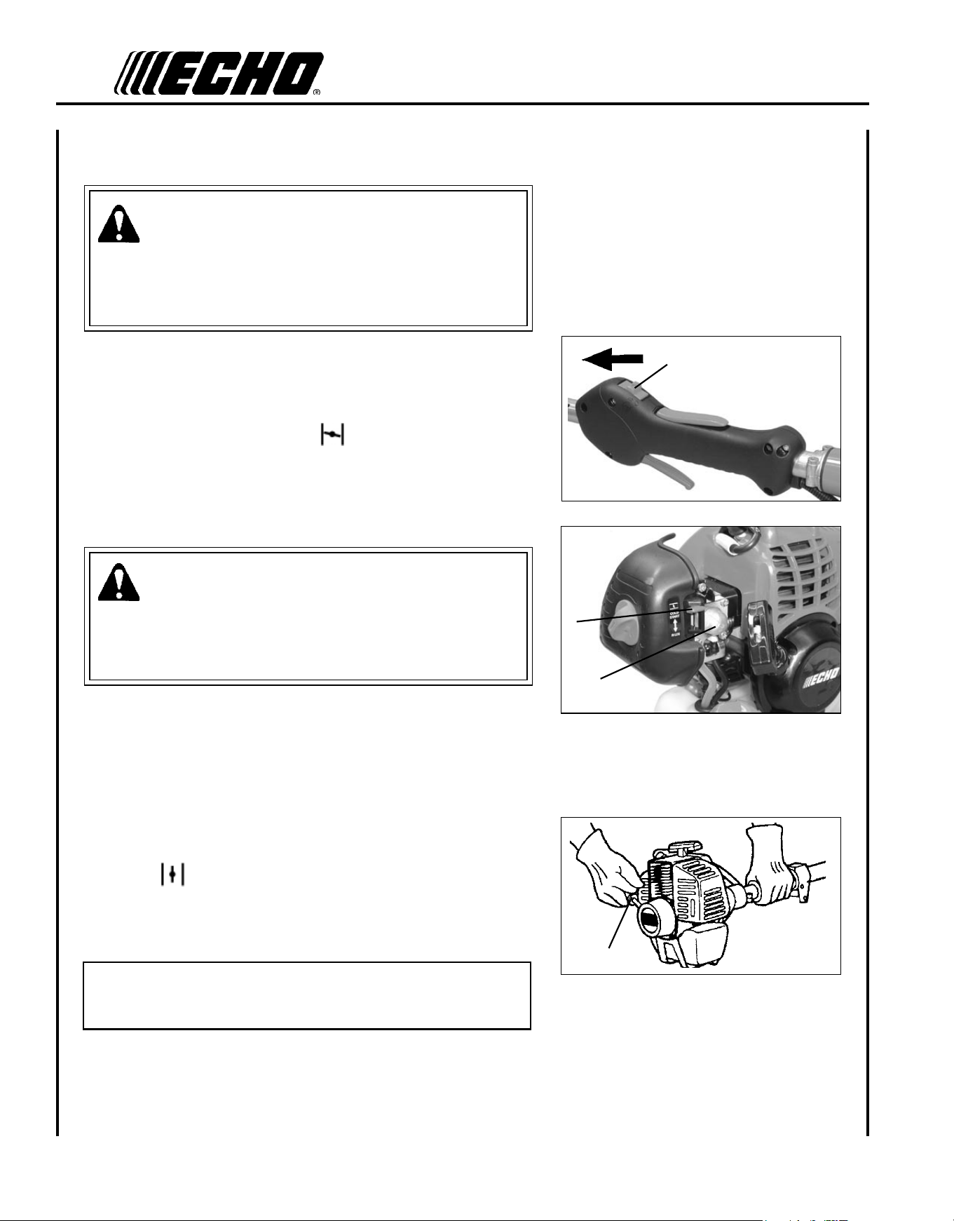
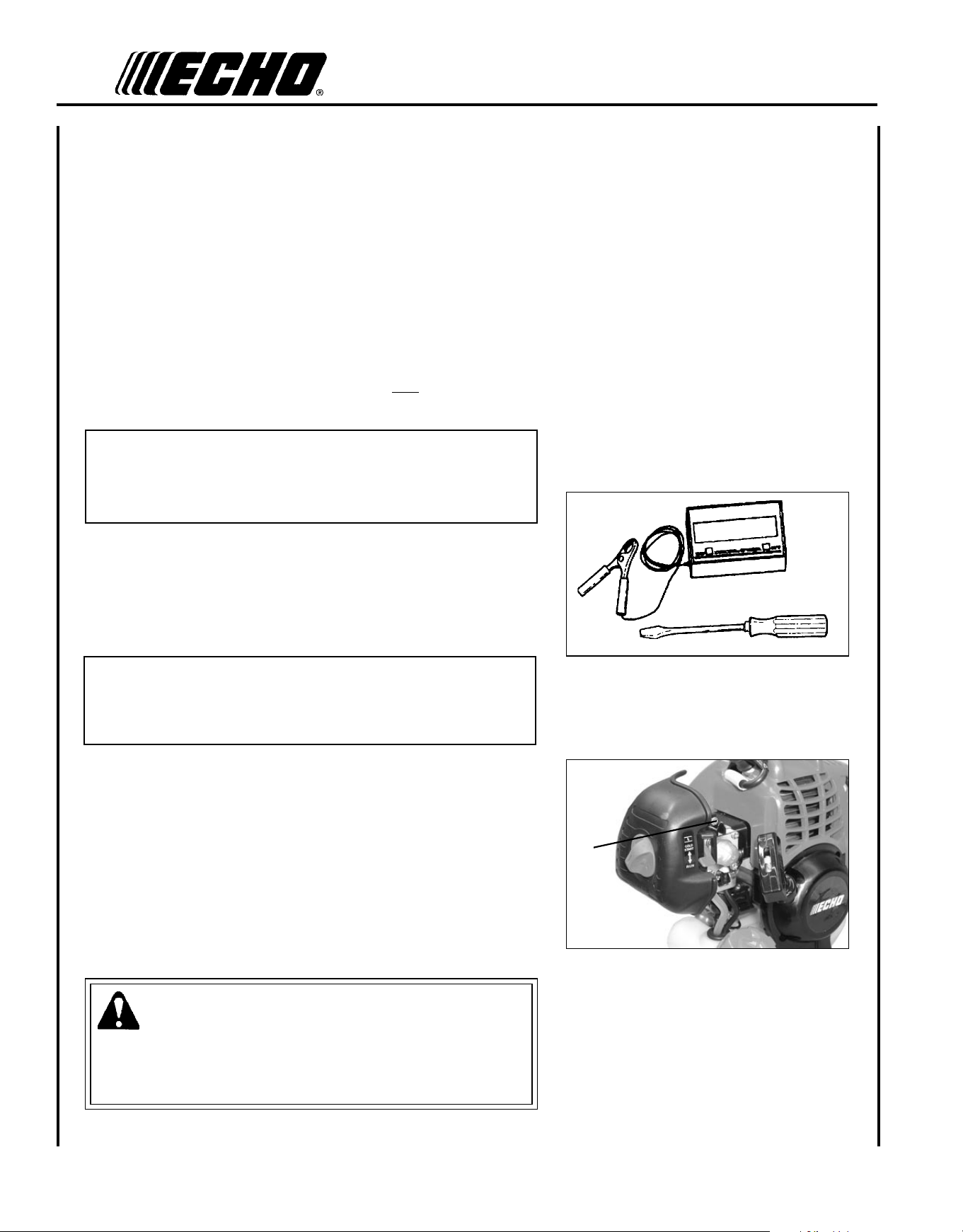
1. Stop Switch
Move stop switch (A) forward away from the STOP position.
2. Choke
Move choke (B) to “Cold Start” ( ) Position.
3. Purge Bulb
Pump purge bulb (C) until fuel is visible and ows freely in the
clear fuel tank return line. Pump bulb an additional 4 or 5 times.
WARNING
Inspect starting area for hazards such as rocks, glass, debris etc.
which could be contacted by the cutting attachment when starting.
Keep helpers and bystanders at least 15 m (50 ft.) from starting
area, otherwise serious personal injury may result.
4. Recoil Starter
Lay the unit on a at area and keep movable attachment parts clear
of all obstacles. Firmly grasp right hand grip and throttle trigger
lockout with left hand and fully depress throttle trigger to wide
open position. Rapidly pull recoil starter handle/rope (D) until
engine res (or maximum ve [5] pulls).
5. Choke
After engine res (or ve [5] pulls), move choke lever back to
“Run” ( ) position. Hold throttle trigger and throttle trigger
lockout fully depressed and pull recoil starter handle/rope until en-
gine starts and runs. Release throttle trigger and allow unit to warm
up at idle for several minutes.
NOTE
If engine does not start with choke in “Run” position after 5 pulls,
repeat instructions 2 - 5.
6. After engine warm up, gradually depress throttle trigger to increase
engine RPM to operating speed.
C
A
B
D
Po w e r Pr u n e r
TM
oP e r a T o r 's Ma n u a l
17
s t a r t I n g w a r m e n g I n e
The starting procedure is the same as Cold Start except DO NOT close
the choke, and do not depress throttle trigger to wide open position.
WARNING
The attachment should not move at idle, otherwise serious personal
injury may result.
NOTE
If attachment moves, readjust carburetor according to “Carburetor
Adjustment” instructions in this manual or see your ECHO Dealer.
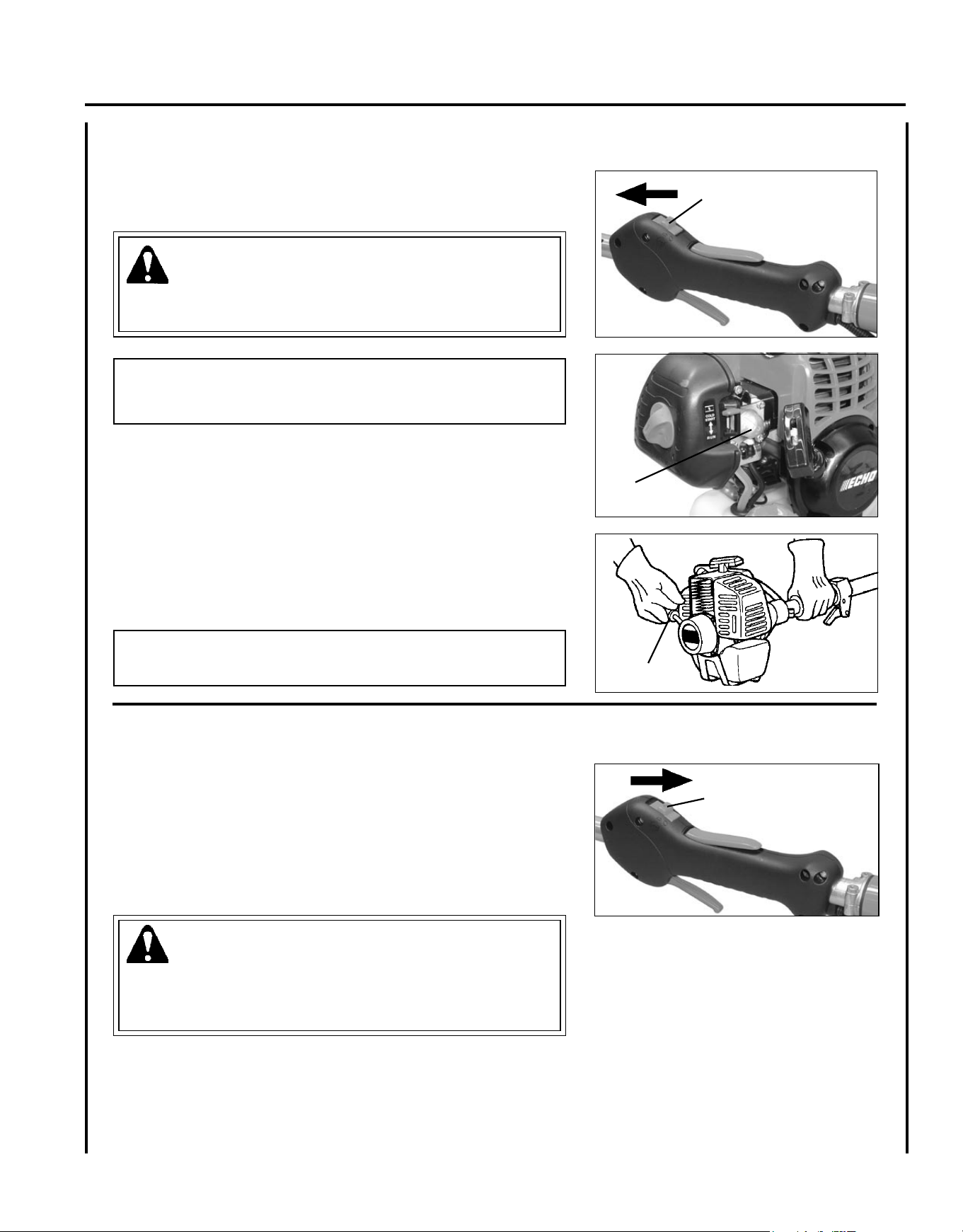
1. Stop Switch
Move stop switch (A) forward away from the STOP position.
2. Purge Bulb
Pump purge bulb (C) until fuel is visible and ows freely in the
clear fuel tank return line. Pump bulb an additional 4 or 5 times.
3. Recoil Starter
Lay the unit on a at, clear area and pull the recoil starter handle
(D) until the engine res.
NOTE
If engine does not start after 5 pulls, use Cold Start Procedure.
s t o p p I n g e n g I n e
1. Throttle
Release throttle and allow engine to return to idle before shutting
engine off.
2. Stop Switch
Move stop switch (A) backward to STOP position.
WARNING
If engine does not stop when stop switch is moved to STOP posi-
tion, close choke - COLD START position - to stall engine. Have
your ECHO dealer repair stop switch before using pruner again.
A
A
C
D
18
blade hIts rear branch
not
correct
p r u n I n g t e c h n I q u e s
WARNING
Engine exhaust IS HOT, and contains Carbon Monoxide (CO), a
poison gas. Breathing CO can cause unconsciousness, serious in-
jury, or death. Exhaust can cause serious burns. ALWAYS position
unit so that exhaust is directed away from your face and body.
The Power Pruner
TM
is designed for light to medium trimming of limbs
and branches up to 203mm (8 in.) in diameter. Follow these tips for
successful operation.
• Plan cut carefully. Check direction branch will fall.
• Plan retreat path from falling branch. Cut branches bounce when
striking ground.
• Long branches should be removed in several pieces.
• Do not stand directly beneath branch being cut.
• When ready to cut:
Hold "cutting shoe" against branch. This will prevent whipping of the
branch. DO NOT use back and forth sawing action.
• Look out for branch immediately behind the branch being cut. If saw
chain hits rear branch damage to saw chain and guide bar may occur.
• Accelerate to full throttle.
• Apply cutting pressure.
• Ease cutting pressure when nearing end of cut to maintain control.
• When pruning a limb 102 mm (4 in.) diameter or larger cut as fol-
lows:
1. Under cut 1/4 limb diameter near tree trunk.
2. Finish top cut slightly farther out on limb.
3. Flush cut stub at trunk.
• DO NOT use for felling or bucking.
not
correct
correct
guIde agaInst
branch
Po w e r Pr u n e r
TM
oP e r a T o r 's Ma n u a l
19
Your ECHO Power Pruner
TM
is designed to provide many hours of trouble free service. Regular scheduled maintenance
will help your pruner achieve that goal. If you are unsure or are not equipped with the necessary tools, you may want to
take your unit to an ECHO Service Dealer for maintenance. To help you decide whether you want to DO-IT-YOUR-
SELF or have the ECHO Dealer do it, each maintenance task has been graded. If the task is not listed, see your ECHO
Service Dealer for repairs.
s k I l l l e v e l s
Level 1 = Easy to do. Common tools may be required.
Level 2 = Moderate difculty. Some specialized tools may be required.
ECHO offers REPOWER
TM
Maintenance Kits and Parts to make your maintenance job easier.
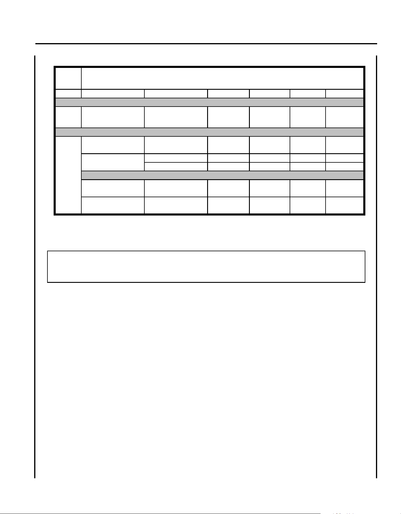
m a I n t e n a n c e I n t e r v a l s
ma I n t e n a n c e
COMPONENT / SYSTEM
MAINTENANCE
PROCEDURE
REQ'D
SKILL
LEVEL
DAILY OR
BEFORE
USE
EVERY
REFUEL
3 MONTHS
OR 90
HOURS
YEARLY 600
HOURS
Air Filter Inspect/Clean 1
I / C * R *
Choke Shutter Inspect/Clean 1
I / C
Fuel Filter Inspect/Replace 1
I * I / R *
Fuel Cap Gasket Inspect/Replace 1
I * R *
Fuel System Inspect/Replace 1
I (2) * I (2) *
Spark Plug Inspect/Clean/Replace 1
I/C/R *
Cooling System Inspect/Clean 2
I / C
Muffler Spark Arrestor Inspect/Clean/Replace 2
I/C/R *
Cylinder Exhaust Port Inspect/Clean/Decarbon 2
I / C
Drive Shaft (Flex Cable
Models
)
Inspect/Grease
2
I (1)
Guide Bar / Sprocket Nose Inspect/Clean/Lubricate 2
I / C * I
Saw Chain
Inspect/Sharpen/
Replace/Tension
2
I * I *
Recoil Starter Rope Inspect/Clean 1
I / C *
Screws/Nuts/Bolts Inspect/Tighten/Replace 1
I *
(2) Low evaporative fuel tanks DO NOT require regular maintenance to maintain emission integrity.
* All recommendations to replace are based on the finding of damage or wear during inspection.
MAINTENANCE PROCEDURE LETTER CODES:
I = INSPECT, R = REPLACE, C = CLEAN
IMPORTANT NOTE
- Time intervals shown are maximum. Actual use and your experience will determine the
frequency of required maintenance.
MAINTENANCE PROCEDURE NOTES:
(1) Apply POWER BLENDX
TM
lubricant every 25 hours of use.
WARNING
Moving parts can amputate ngers or cause severe injuries. Keep hands, clothing and loose objects away from all
openings. Always stop engine, disconnect spark plug, and make sure all moving parts have come to a complete
stop before removing obstructions, clearing debris, or servicing unit. Allow unit to cool before performing service.
Wear gloves to protect hands from sharp edges and hot surfaces.
20
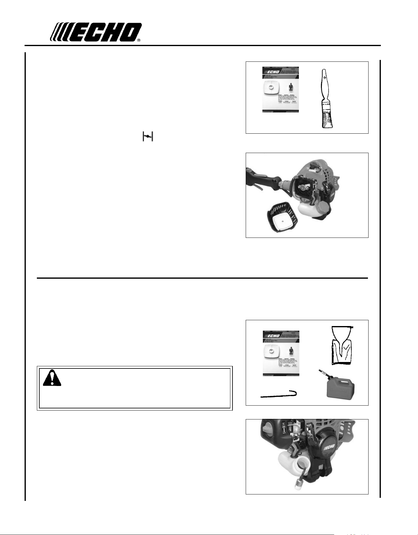
a I r f I l t e r
Level 1.
Tools required: 25 - 50 mm (1 - 2 in.) Cleaning Brush
Parts required: REPOWER
TM
AIR & FUEL FILTER KIT.
1. Close choke (Cold Start Position [
]). This prevents dirt from
entering the carburetor throat when the air lter is removed. Brush
accumulated dirt from air cleaner area.
2. Remove air lter cover. Brush dirt from inside cover.
3. Remove air lter and lightly brush debris from lter. Replace lter
if it is damaged, fuel soaked, very dirty, or the rubber sealing edges
are deformed.
4. If lter can be reused, be certain it:
• Fits tightly in the air lter cavity.
• Is installed with the original side out.
5. Install air lter cover.
f u e l f I l t e r
Level 1.
Tools required: 200 - 250 mm (8 - 10 in.) length of wire with one
end bent into a hook, clean rag, funnel, and an
approved fuel container
Parts required: REPOWER
TM
AIR & FUEL FILTER KIT.
DANGER
Fuel is VERy ammable. Use extreme care when mixing, storing
or handling, or serious personal injury may result.
1. Use a clean rag to remove loose dirt from around fuel cap and
empty fuel tank.
2. Use the “fuel line hook” to pull the fuel line and lter from the
tank.
3. Remove the lter from the line and install the new lter.
Po w e r Pr u n e r
TM
oP e r a T o r 's Ma n u a l
21
s p a r k p l u g
Level 2.
Tools Required: T-Wrench, feeler gauge, Soft metal brush
Parts Required: REPOWER
TM
Tune-Up Kit
IMPORTANT
Use only NGK BPM-8Y spark plug (BPMR-8Y in Canada)
otherwise severe engine damage may occur.
1. Remove spark plug and check for fouling, worn and rounded center
electrode.
2. Clean the plug or replace with a new one. DO NOT sand blast to
clean. Remaining sand will damage engine.
3. Adjust spark plug gap 0.65mm (0.026 in.) by bending outer elec-
trode.
4. Tighten spark plug to 150-170 kgf • cm (130-150 in. • lbf).
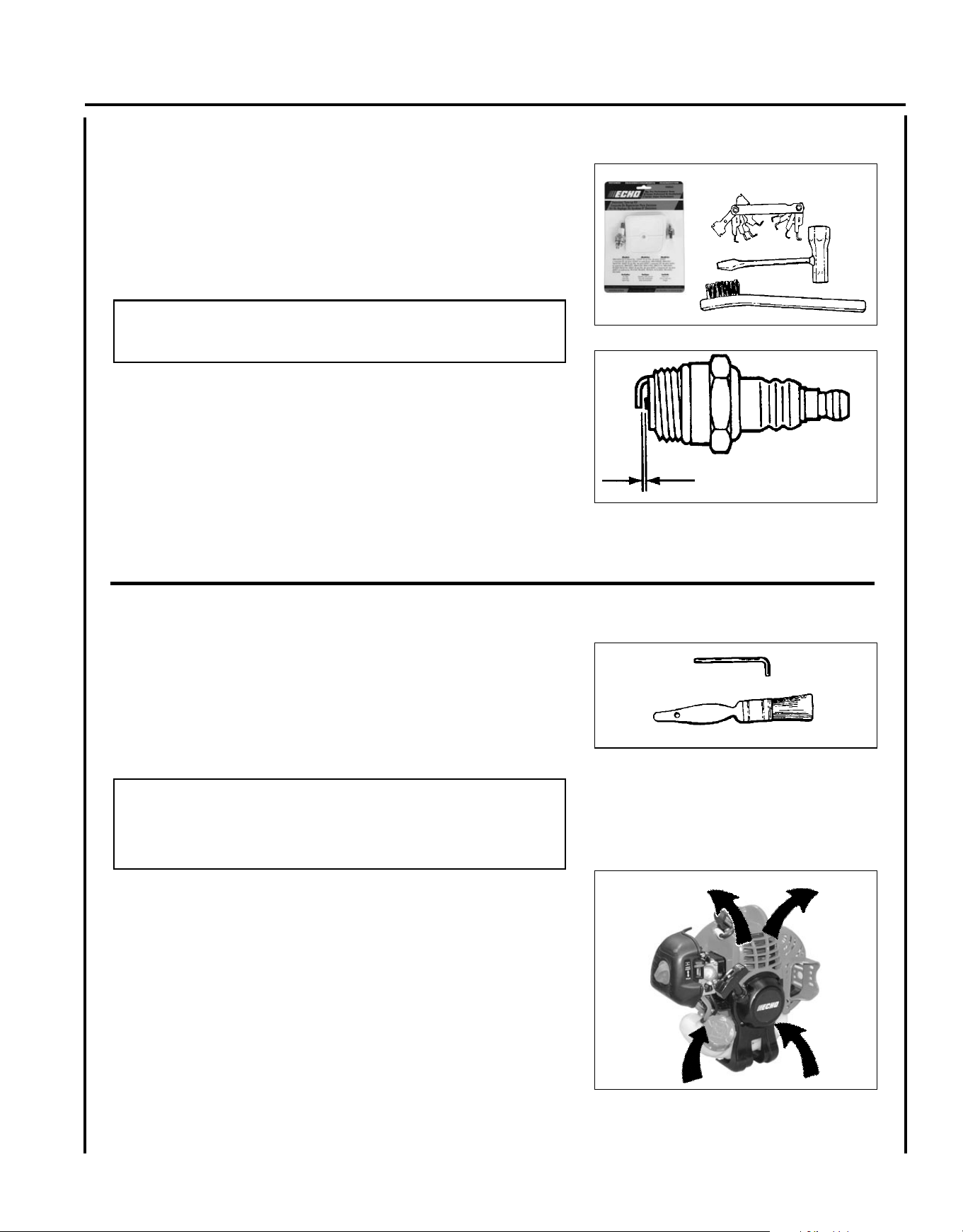
c o o l I n g s y s t e m c l e a n I n g
Level 2.
Tools Required: T27 Torx L-Wrench, Cleaning Brush, 25 - 50 mm
(1 - 2 in.)
Parts Required: None.
IMPORTANT
To maintain proper engine operating temperatures, cooling air must
pass freely through the cylinder n area. This ow of air carries
combustion heat away from the engine.
Overheating and engine seizure can occur when:
• Air intakes are blocked, preventing cooling air from reaching the
cylinder.
• Dust and grass build up on the outside of the cylinder. This build
up insulates the engine and prevents the heat from leaving.
Removal of cooling passage blockages or cleaning of cooling ns is
considered “Normal Maintenance.” Any failure attributed to lack of
maintenance is not warranted.
0.65 mm
(0.026 in.)
22
1. Remove spark plug lead.
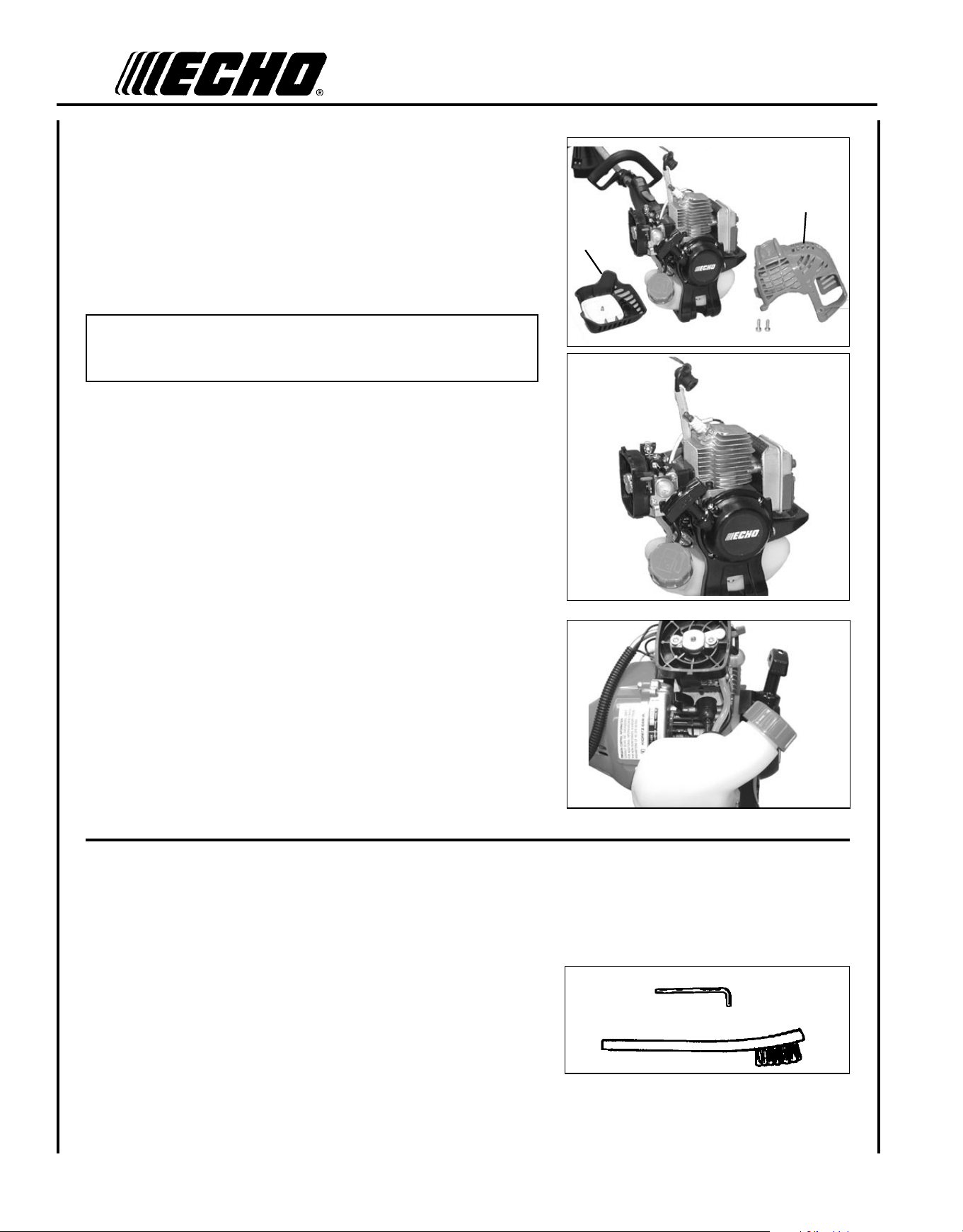
2. Remove air cleaner cover (A).
3. Remove 2 engine cover screws and engine cover (B).
(1 machine screw - handle side)
(1 tapping screw - starter side)
IMPORTANT
DO NOT use a metal scraper to remove dirt from the cylinder ns.
4. Remove ignition wires from clip for cleaning.
5. Use brush to remove dirt from the cylinder ns.
6. Remove grass and leaves from the grid between the recoil starter
and fuel tank.
7. Assemble components in reverse order.
A
B
e X h a u s t s y s t e m
Spark Arrestor Screen
Level 2.
Tools Required: T27 Torx L-Wrench, Soft Metal Brush
Parts Required: Spark Arrestor Screen, Gasket
Po w e r Pr u n e r
TM
oP e r a T o r 's Ma n u a l
23
Exhaust Port Cleaning
Level 2
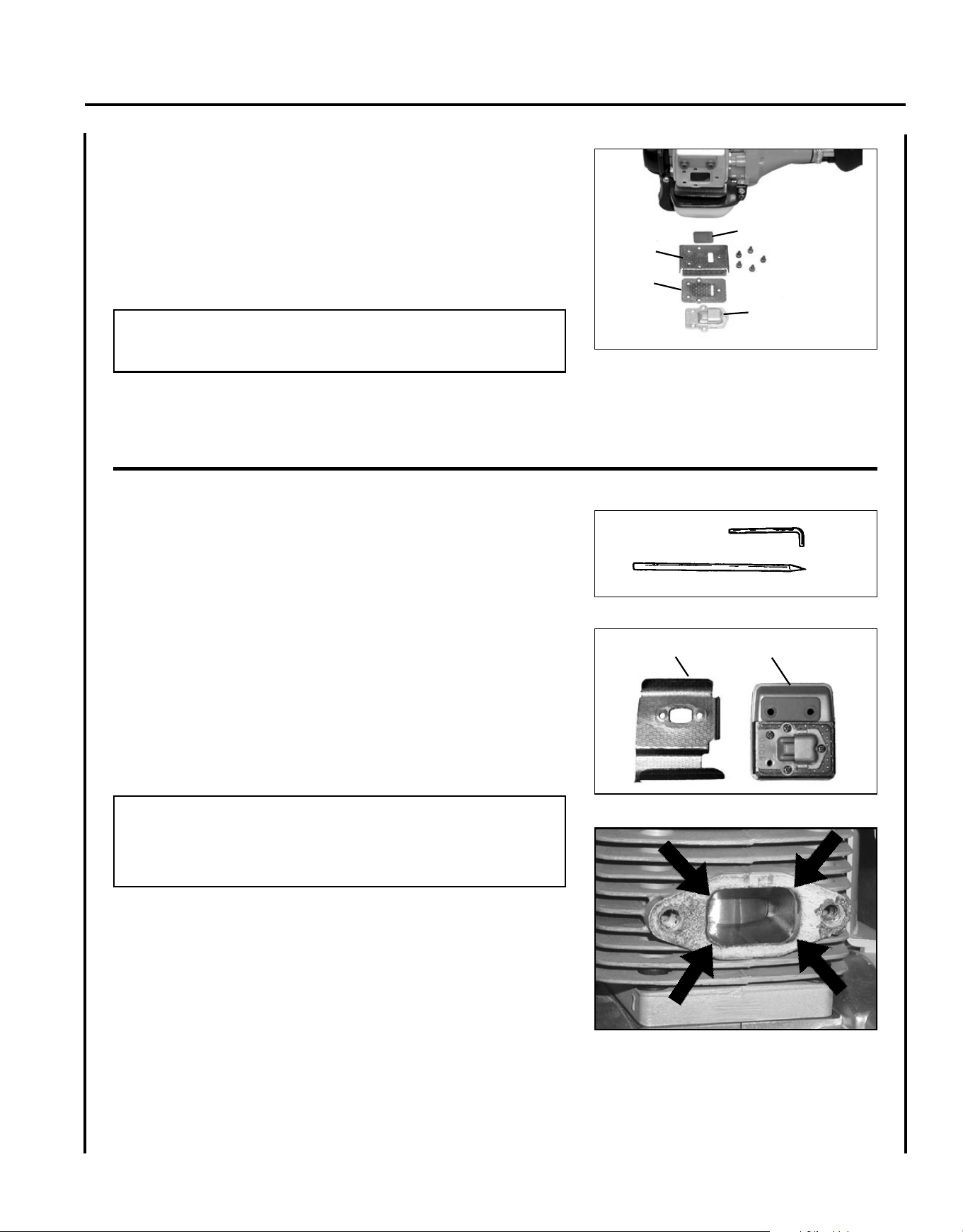
Tools required: T27 Torx L-Wrench, Wood or plastic scraper
Parts Required: As needed: Heat Shield
1. Remove spark plug lead from spark plug, and remove engine cover
(2 screws).
2. Place piston at top dead center. Remove mufer (A) and heat
shield (B).
3. Use a wood or plastic scraping tool to clean deposits from cylinder
exhaust port.
IMPORTANT
Never use a metal tool to scrape carbon from the exhaust port.
Do not scratch the cylinder or piston when cleaning the exhaust
port. Do not allow carbon particles to enter the cylinder.
4. Inspect heat shield, and replace if damaged.
5. Install heat shield and mufer.
6. Tighten mufer mounting bolts (or nuts) to 80-95 in•lbf
(90-110 kgf•cm).
7. Install engine cover and attach spark plug lead.
8. Start engine, and warm to operating temperature.
9. Stop engine, and re-tighten mounting bolts (or nuts) to specica-
tions.
C
E
F
D
1. Remove engine cover screws (2) and engine cover.
2. Place piston at Top Dead Center (TDC) to prevent carbon/dirt from
entering cylinder.
3. Remove spark arrestor screen cover (C), gaskets (D), (E), and
screen (F), from mufer body.
4. Clean carbon deposits from mufer components.
NOTE
When cleaning carbon deposit, be careful not to damage the cata-
lytic element inside mufer.
5. Replace screen if it is cracked, plugged, or has holes burned
through.
6. Assemble components in reverse order.
A
B
24
c a r b u r e t o r a d j u s t m e n t
Engine Break-In
New engines must be operated a minimum duration of two tanks of fuel
break-in before carburetor adjustments can be made. During the break-
in period your engine performance will increase and exhaust emissions
will stabilize. Idle speed can be adjusted as required.
High Altitude Operation
This engine has been factory adjusted to maintain satisfactory starting,
emission, and durability performance up to 1,100 feet above sea level
(ASL) (96.0 kPa). To maintain proper engine operation and emission
compliance above 1,100 feet ASL the carburetor may need to be ad-
justed by an authorized ECHO service dealer.
IMPORTANT
If the engine is adjusted for operation above 1,100 feet ASL, the
carburetor must be re-adjusted when operating the engine below
1,100 feet ASL, otherwise severe engine damage may result.
Level 2.
Tools required: Screwdriver, Tachometer (ECHO P/N
99051130017).
Parts required: None.
NOTE
Every unit is run at the factory and the carburetor is set in compli-
ance with emission regulations. Carburetor adjustments, other than
idle speed, must be performed by an authorized ECHO dealer.
1. Before adjusting the carburetor, clean or replace the air lter and
spark arrestor screen.
2. Start engine and run for several minutes to reach operating tem-
perature.
3. Check idle speed and reset if necessary. If a tachometer is avail-
able, idle speed screw (A) should be set to the specications found
on page 31 "Specications" of this manual. Turn idle screw (A)
clockwise to increase idle speed; counter clockwise to decrease
idle speed.
WARNING
When carburetor adjustment is completed, the cutting attachment
should not turn at idle, otherwise serious personal injury may
result.
A
Po w e r Pr u n e r
TM
oP e r a T o r 's Ma n u a l
25
g u I d e b a r a n d s a w c h a I n r e p l a c e m e n t
WARNING
Never try to replace or adjust guide bar and saw chain with engine running. Always disconnect spark plug wire
before servicing guide bar and saw chain. This saw chain is VERY sharp, wear heavy gloves to protect your hands
when handling it. Wear eye protection meeting CE or ANSI specication Z87.1.
Guide Bar Replacement / Installation
Level 2
Tools Required: T-Wrench, T27 Torx L-Wrench
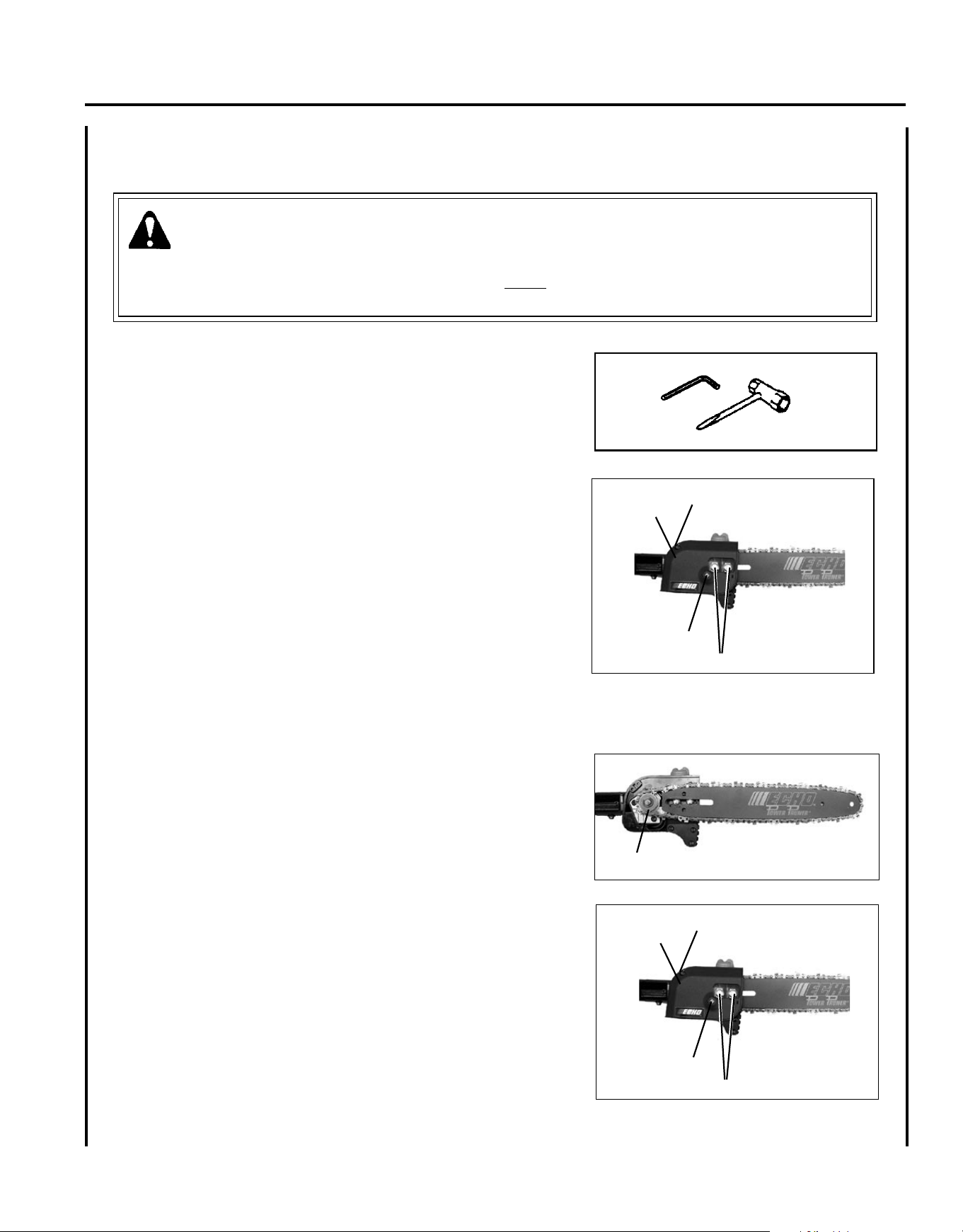
1. Remove two (2) 6 mm guide bar nuts (A) and guide bar cover
screw (B), and turn saw chain tension adjustment screw (C) coun-
terclockwise to release tension.
2. Remove guide bar cover (D).
3. Remove guide bar and saw chain from gear case and sprocket.
4. Remove chain from guide bar and check guide bar for damage and
excessive or uneven wear. Replace guide bar if necessary.
5. Install chain on guide bar with cutters on top of bar facing toward
bar tip.
6. Install guide bar and chain on gear case, engaging chain with drive
sprocket (E).
7. Turn tension adjustment screw clockwise to take up slack in saw
chain.
8. Install guide bar cover (D), and tighten guide bar nuts nger tight
and install guide bar cover screw (B).
9. Adjust chain tension.
E
A
B
B
D
A
B
B
D
26
a
B
To Adjust Saw Chain Tension
1. Move stop switch to STOP position.
2. Disconnect spark plug lead.
3. Loosen two guide bar nuts (A) until nger tight.
4. Hold the bar nose up, and turn the adjuster screw (B) clockwise un-
til the chain ts snugly against the underside of the bar, as shown.
Cold Chain Only - turn adjuster screw CW an additional 1/8 - 1/4
turn.
5. Tighten both guide bar nuts with nose held up. Tighten rear nut
rst.
6. Pull the chain around the guide bar by hand. Reduce the chain ten-
sion if you feel tight spots.
7. When chain is properly tensioned, tighten guide bar nuts securely.
IMPORTANT
Tighten guide bar nuts to 8 - 9 N•m (71 - 80 in. lbs.) DO NOT
over-tighten nuts. Damage may result.
8. Keep chain properly tensioned at all times.
NOTE
All chains require frequent adjustment.
9. Connect spark plug lead.
Guide Bar Cover Cleaning
Tools Required: 10 x 19 mm (13/32 x 3/4 in.) T-wrench, T27 Torx
L-Wrench
1. Remove two (2) 6 mm guide bar nuts (A) and guide bar cover
screw (B).
2. Remove guide bar cover (D).
3. Gently brush debris from inside guide bar cover and from around
sprocket.
4. Install guide bar cover (D), install and tighten guide bar nuts, and
install guide bar cover screw (B).
A
B
B
D
Po w e r Pr u n e r
TM
oP e r a T o r 's Ma n u a l
27
IMPORTANT
Chain and guide bar gauge size must be identical. Use Bar/Chain combinations shown in table above.
* Multicut
TM
Chain - extra chrome plating for dirty or abrasive conditions.
Bar P/N Chain P/N Chain Type Links Pitch Gauge
M91VX44CQ * 91 44 3/8" 0.050
91VX44CQ 91 44 3/8" 0.050
12" Regular Bar
P/N 12AOCD3744
Standard
Optional
Narrow Kerf
PPF-225 Standard Bar and Chain Combinations
39 3/8" 0.050
39 3/8" 0.050
0.043
10" regular bar P/N
10AOCD3739
91VX39CQ 91
3/8"
3/8" 0.043
10" Narrow Bar
P/N 10A4CD3739
90SG39CQ 90 39
449090SG44CQ
12" Narrow Bar
P/N 12A4CD3744
10" regular bar P/N
10AOCD3739
M91VX39CQ * 91
28
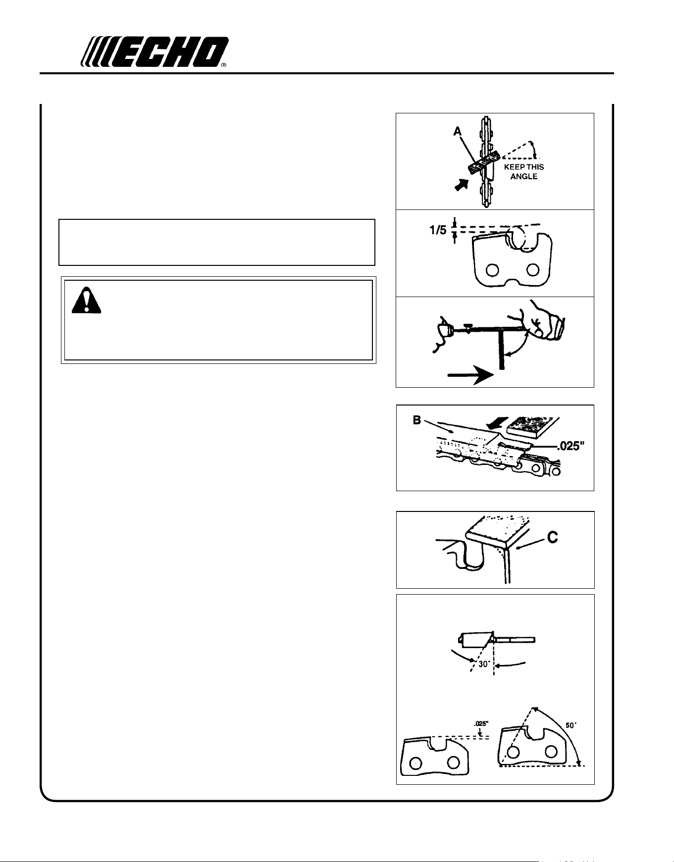
f I l I n g s a w c h a I n
Level 3.
Tools required: 4 mm (5/32 in.) Round File, Flat File, Depth Gauge
IMPORTANT
Dull or damaged cutters will result in poor cutting performance,
increased vibration, and premature saw chain failure.
WARNING
Always stop engine and disconnect spark plug wire before servic-
ing guide bar and saw chain. Always wear gloves when ling saw
chain, otherwise serious personal injury may result.
1. Set round le (A) in cutter at 30° angle. One fth (1/5) of the le
should be exposed above top cutter edge.
2. Keep le horizontal in cutter and le in one direction.
3. File until cutter top and side bevel edges are sharp without nicks.
4. Place depth gauge tool (B) rmly on top of cutter with .025 in. slot
and end against front cutter raker. File cutter raker with at le
until ush with top of depth gauge.
5. Finish cutter sharpening by rounding front raker edge (C) with at
le.
6. Properly led cutter is as shown.
7. Apply clean oil and rotate saw chain slowly to wash away lings.
8. If saw chain is coated or clogged with resin, clean in kerosene,
then soak in oil.
1
2
3
4
5
30°
90°
(TOP PLATE ANGLE)
(DEPTH GAUGE)
(TOP PLATE CUTTING ANGLE)
6

Po w e r Pr u n e r
TM
oP e r a T o r 's Ma n u a l
29
tr o u b l e s h o o t I n g
WARNING
Fuel vapors are extremely ammable and may cause re and/or explosion. Never test for ignition spark by
grounding spark plug near cylinder plug hole, otherwise serious personal injury may result.
TRAHCGNITOOHSELBUORTMELBORPENIGNE
melborPkcehCsutatSesuaCydemeR
enigne
-sknarc
/drahstrats
t'nseod
trats
roterubractaleufroterubractaleufoNdeggolcreniartsleuf
deggolcenilleuf
roterubraC
ecalperronaelC
ecalperronaelC
relaedohceruoyees
rednilyctaleufrednilyctaleufoNroterubraCrelaedohceruoyees
leufhtiwtewrelffumhcirooterutximleufekohcnepO
retlifriaecalper/naelC
roterubractsujda
relaedohceruoyees
dnetakraps
eriwgulpfo
krapsoNffohcti
wspots
melborplacirtcele
hctiwskcolretni
NOothctiwsnruT
relaedohceruoyees
relaedohceruoyees
gulptakrapskrapsoNtcerrocnipagkraps
nobrachtiwderevoC
leufhtiwdeluof
evitcefedgulP
).ni620.0(mm56.ottsujda
ecalperronaelC
ecalperronaelC
gulpecalper
,snurenigne
roseidtub
tonseod
etarelecca
ylreporp
retlifriaytridretlifriaraewlamroNecalperronaelC
retlifleufytridretlifleufseudiser/stnanimatnoCni
leuf
ecalper
tnevleufdeggulptnevleufniseudise
r/stnanimatnoC
leuf
ecalperronaelC
gulPkrapsnrow/ytridgulPraewlamroNecalperrotsujdadnanaelC
roterubraCtnemtsujdareporpminoitarbiVtsujda
metsysgnilooCmetsysgnilooC
deggulp/ytrid
ninoitarepodednetxe
snoitacolytsud/ytrid
naelC
rotserrakraps
neercs
rotserrakraps
deggulpneercs
raewlamroNecalper
seodenigne
knarcton
a/Na/Nmelborpenignelanretnirelaedohceruoyees
30
st o r a g e
Long Term Storage (over 30 days)
WARNING
During operation the mufer or catalytic mufer and surrounding cover become hot. Always keep exhaust area clear
of ammable debris during transportation or when storing, otherwise serious property damage or personal injury
may result.
Do not store your unit for a prolonged period of time (30 days or longer) without performing protective storage mainte-
nance which includes the following:
1. Store unit in a dry, dust free place, out of the reach of children.
DANGER
Do not store in enclosure where fuel fumes may accumulate or reach an open ame or spark or serious personal
injury may result.
2. Place the stop switch in the "OFF" position.
3. Remove accumulation of grease, oil, dirt and debris
from exterior of unit.
IMPORTANT
Some tree sap and resins are corrosive. Thoroughly
wash the guide bar and sprocket areas after each
use, then coat metal parts with light oil.
4. Perform all periodic lubrication and services that
are required.
5. Tighten all the screws and nuts.
6. Drain the fuel tank completely and pull the recoil
starter handle several times to remove fuel from the
carburetor.
7. Remove the spark plug and pour 7 cc (1/4 oz.) of
fresh, clean, two-stroke engine oil into the cylinder
through the spark plug hole.
A. Place a clean cloth over the spark plug hole.
B. Pull the recoil starter handle 2-3 times to
distribute the oil inside the engine.
C. Observe the piston location through the spark
plug hole. Pull the recoil starter handle slowly
until the piston reaches the top of its travel and
leave it there.
8. Install the spark plug (do not connect spark plug
cable).
9. Install the guide bar cover on the guide bar and saw
chain during storage.

Po w e r Pr u n e r
TM
oP e r a T o r 's Ma n u a l
31
sp e c I f I c a t I o n s
MODEL ---------------------------------------------------- PPF-225
Length ------------------------------------------------------ 2.455 m (96.7 in.)
Width -------------------------------------------------------- 246 m (9.69 in.)
Height ------------------------------------------------------- 235 m (9.25 in.)
Weight (dry) ------------------------------------------------ 6.3 kg (13.9 lb.)
Engine Type ------------------------------------------------ Air cooled, two-stroke, single cylinder gasoline engine
Bore ---------------------------------------------------------- 32.2 mm (1.27 in.)
Stroke -------------------------------------------------------- 26.0 mm (1.02 in.)
Displacement ----------------------------------------------- 21.2 cc (1.29 cu. in.)
Exhaust System -------------------------------------------- Spark arrestor mufer or spark arrestor mufer with catalyst
Carburetor--------------------------------------------------- Zama w/primer bulb
Ignition System -------------------------------------------- CDI (capacitor discharge ignition)
Spark Plug -------------------------------------------------- NGK BPM-8Y Gap 0.65 mm (0.026 in.)
Fuel ---------------------------------------------------------- Mixed (Gasoline and Two-stroke Oil)
Fuel/Oil Ratio ---------------------------------------------- 50 : 1 Power Blend X™ ISO-L-EGD (ISO/CD 13738) and
J.A.S.O. M345- FC/FD, two-stroke, air-cooled engine oil.
Gasoline ----------------------------------------------------- Use 89 Octane unleaded. Do not use fuel containing methyl
alcohol, more than 10% ethyl alcohol or 15% MTBE. Do not use
alternative fuels such as E-15 or E-85.
Oil ------------------------------------------------------------ Power Blend X
TM
Premium Universal 2-Stroke Oil
Fuel Tank Capacity ---------------------------------------- 0.44 lit. (14.9 US . oz.)
Recoil Starter System ------------------------------------- Automatic Recoil Starter
Clutch-------------------------------------------------------- Centrifugal Type
Sprocket Type ---------------------------------------------- 6 tooth spur, 9.53 mm (3/8 inch) pitch
Shaft Tube Assembly -------------------------------------- 25 mm (1 in.) Galvanized Steel
Drive Shaft ------------------------------------------------- 6.35 mm (1/4 inch) Flex Cable
Gear Case Ratio -------------------------------------------- 1.53
Oiling System ---------------------------------------------- Automatic
Chain Oil Capacity ---------------------------------------- .2 L (6.76 oz.)
Handles ------------------------------------------------------ Right hand grip w/throttle trigger and throttle trigger lockout / Left
foam hand grip
Shoulder Harness ------------------------------------------ Standard
Idle Speed (RPM) ------------------------------------------ 2,500 - 3,400
Clutch Engagement Speed (RPM) ----------------------- 4,300
Wide Open Throttle Speed (RPM) ---------------------- 10,400 - 11,400
Guide Bar and Saw Chain (91) -------------------------- 254 mm (10 in.); 9.53 mm (3/8 inch) pitch chain, 0.050 gauge

32
wa r r a n t y st a t e m e n t s
ECHO LIMITED WARRANTY STATEMENT FOR
PRODUCT SOLD IN USA AND CANADA BEGINNING 01/01/2010
ECHO'S RESPONSIBILITY
ECHO Incorporated’s Limited Warranty, provides to the original purchaser that this ECHO product is free from defects in material and workmanship.
Under normal use and maintenance from date of purchase, ECHO agrees to repair or replace at ECHO’s discretion, any defective product
free of charge at any authorized ECHO servicing dealer within listed below application time periods, limitations and exclusions. THIS LIMITED
WARRANTY IS ONLY APPLICABLE TO ECHO PRODUCTS SOLD BY AUTHORIZED ECHO DEALERS. IT IS EXTENDED TO THE ORIGINAL
PURCHASER ONLY, AND IS NOT TRANSFERABLE TO SUBSEQUENT OWNERS EXCEPT FOR EMISSION RELATED PARTS. Repair
parts and accessories replaced under this warranty are warranted only for the balance of the original unit or accessory warranty period. Any
damage caused by improper installation or improper maintenance is not covered by this warranty. All parts or products replaced under warranty
become the property of ECHO, Inc. This warranty is separate from the Emission control warranty statement supplied with your new product.
Please consult the Emission Control Warranty Statement for details regarding emission related parts. For a list of Authorized ECHO Dealers
refer to WWW.ECHO-USA.COM or call 1-800-432-ECHO.
OWNER’S RESPONSIBILITY
To ensure trouble free warranty coverage it is important that you register your ECHO equipment on-line at WWW.ECHO-USA.COM or by ll-
ing out the warranty registration card supplied with your unit. Registering your product conrms your warranty coverage and provides a direct
link if we nd it necessary to contact you.
The owner shall demonstrate reasonable care and use, and follow preventative maintenance, storage, fuel and oil usage as prescribed in the
operator’s manual. Should a product difculty occur, you must, at your expense, deliver or ship your ECHO unit to an authorized ECHO servicing
dealer for warranty repairs (within the applicable warranty period), and arrange for pick-up or return of your unit after the repairs have been
made. For your nearest authorized ECHO servicing dealer, call ECHO’s Dealer Referral Center, at 1-800-432-ECHO or you can locate an ECHO
servicing dealer at WWW.ECHO-USA.COM. Should you require assistance or have questions concerning ECHO’s Warranty Statement, you
can contact our Consumer Product Support Department at 1-800-673-1558 or contact us through the web at WWW.ECHO-USA.COM.
PRODUCT WARRANTY PERIOD
RESIDENTIAL APPLICATION
• 5 YEAR WARRANTY - All units for residential, or non-income producing use will be covered by this limited warranty for ve (5) years from
date of purchase.
EXCEPTIONS:
• For two-stroke engine powered products, the electronic ignition module, exible drive cables, SRM solid drive shafts, and TC tines
are warranted for the life* of the product on parts only.
• Cutting attachments such as, but not limited to, bars, chains, sprockets, blades, and nylon trimmer heads for residential or non-income
producing use will be covered for failures due to defects in material or workmanship for a period of 60 days from original product
purchase date. Any misuse from contact with concrete, rocks, or other structures is not covered by this warranty.
• ECHO’s Rapid Loader String Head carries a lifetime warranty on the line locking system, parts only; no labor. Refer to your operator’s
manual for string head installation and maintenance instructions.
• All SB-Series and PRO ATTACHMENT SERIES Split Shaft attachments carry the same warranty duration as the units they are
designed to t.
COMMERCIAL APPLICATION
• 1 YEAR WARRANTY - All Chain Saws, QuikVent Saws, and Cut-Off Saws for commercial, institutional, agricultural, industrial, or income
producing use will be covered by this limited warranty for one (1) year from the date of purchase.
• 2 YEAR WARRANTY - All other units for commercial, institutional, agricultural, industrial, or income producing use will be covered by this
limited warranty for two (2) years from the date of purchase.
EXCEPTIONS:
• For two-stroke engine powered products, the electronic ignition module, exible drive cables, SRM solid drive shafts and TC tines,
are warranted for the life* of the product on parts only.
• Cutting attachments such as, but not limited to, bars, chains, sprockets, blades, and nylon trimmer heads for commercial, institutional,
agricultural, industrial, rental, or income producing will be covered for failures due to defects in material or workmanship for a period
of 30 days from original product purchase date. Any misuse from contact with concrete, rocks, or other structures is not covered by
this warranty.
• ECHO’s Rapid Loader String Head carries a lifetime warranty on the line locking system, parts only; no labor. Refer to your operator’s
manual for string head installation and maintenance instructions.
• All SB-Series and PRO ATTACHMENT SERIES Split Shaft attachments carry the same warranty duration as the units they are
designed to t.
RENTAL APPLICATION - 90 DAYS WARRANTY
• Units for rental use will be covered against defects in material and workmanship for a period of 90 days from the date of purchase.
* ECHO’s liability under the “Lifetime” coverage is limited to furnishing parts specied under the PROdUCT wARRANTy PERIOd section of
this warranty statement for “Life” free of charge for a period of ten (10) years after the date of the complete unit’s nal production.

Po w e r Pr u n e r
TM
oP e r a T o r 's Ma n u a l
33
PURCHASED REPAIR PARTS, SHORT BLOCKS AND ACCESSORIES
• 90-day residential, or non-income producing warranty
• 30-day commercial, institutional, agricultural, industrial, income producing, or rental application warranty
ATTENTION TWO-STROKE ENGINE POWER PRODUCT OWNERS
This ECHO two-stroke engine power product is a quality-engineered unit which has been manufactured to exact tolerances to provide superior
performance. To help ensure the performance of the unit, it is required to use two-stroke oil which meets the ISO-L-EGD Standard per ISO/CD
13738 and JASO M345/FC/FD Standards. ECHO Power Blend™ Two-Stroke Oil is a premium two-stroke oil specically formulated to meet
ISO-L-EGD (ISO/CD 13738) and JASO M345/FC/FD Standards. The use of two-stroke oils designed for other applications, such as for outboard
motors or lawnmowers can result in severe engine damage, and will void your two-stroke engine limited warranty.
THIS WARRANTY DOES NOT COVER DAMAGE CAUSED BY:
• Lack of lubrication or engine failure, due to the use of two-stroke oils that do not meet the ISO-L-EGD (ISO/CD 13738) and JASO M345/
FC/FD Standards. Engine problems due to inadequate lubrication caused by failure to use an ISO-L-EGD compliant and JASO M345/FC/
FD registered oil, will void the two-stroke engine limited warranty. ECHO Power Blend™ Two-Stroke Oil meets the ISO-L-EGD and JASO
M345/FC/FD Standard. Emission related parts are covered for 5 years residential use or 2 years commercial use regardless of two-stroke
oil used, per the statement listed in the EPA or California Emission Defect Warranty Explanation.
• damage caused by use of gasohol, containing methanol (wood alcohol), or gasoline containing less than 89 octane. Only use gasoline which
contains 89 octane or higher. Gasohol which contains a maximum 10% ethanol (grain alcohol) or 15% MTBE (methyl/tertiary/butyl/ether)
is also approved. The prescribed mixing ratio of gasoline to oil is listed on the ECHO oil label and covered in your operator’s manual.
• Engine damage caused by use of ether or any starting uids.
• damage caused by tampering with engine speed governor or emission components, or running engines above specied and recommended
engine speeds as listed in your operator’s manual.
• Operation of the unit with improperly maintained/removed cutting shield or removed/damaged air lter.
• damage caused by dirt, pressure or steam cleaning the unit, salt water, corrosion, rust, varnish, abrasives, and moisture.
• defects, malfunctions or failures resulting from abuse, misuse, neglect, modications, alterations, normal wear, improper servicing, or use
of unauthorized attachments.
• Incorrect storage procedures, stale fuel, including failure to provide or perform required maintenance services as prescribed in the operator's
manual. Preventative maintenance as outlined in the operators manual is the customer’s responsibility.
• Failures due to improper set-up, pre-delivery service or repair service by anyone other than authorized ECHO servicing dealer during the
warranty period.
• Certain parts and other items are not warranted, including but not limited to: lubricants, starter cords, and engine tune-ups.
• Use of spark plugs other than those meeting performance and durability requirements of the OEM spark plug listed in the Operator's
Manuals.
• Overheating or carbon scoring failures due to restricted, clogged exhaust port or combustion chamber, including damage to spark arrester
screen.
• Adjustments after the rst (30) thirty days and beyond, such as carburetor adjustment and throttle cable adjustment.
• damage to gears or gear cases caused by contaminated grease or oil, use of incorrect type or viscosity of lubricants, and/or failure to comply
with recommended grease or oil change intervals.
• damage caused by loading SHREd 'N' VAC
®
beyond recommended capacity.
• damage caused by pump or sprayer running dry, pumping or spraying caustic or ammable materials, or lack of or broken strainers.
• Additional damage to parts or components due to continued use after operational problem or failure occurs. Should operational problem or
failure occur, the product should not be used, but delivered as is to an authorized ECHO servicing dealer.
It is a dealer’s and/or customer’s responsibility to complete and return the warranty registration card supplied with your ECHO product or by visiting
WWW.ECHO-USA.COM. your receipt of purchase including date, model and serial number must be maintained and presented to an authorized
ECHO servicing dealer for warranty service. Proof of purchase rests solely with the customer. Some states do not allow limitations on how long
an implied warranty lasts, so the above limitations may not apply to you. Some states do not allow the exclusion or limitation of incidental or
consequential damages, so you may also have other specic legal rights which vary from state to state. This limited warranty is given by ECHO
Incorporated, 400 Oakwood Rd., Lake Zurich, IL 60047.
DISCLAIMER OF IMPLIED WARRANTIES
This limited warranty is in lieu of all other expressed or implied warranties, including any warranty of FITNESS FOR A PARTICULAR PURPOSE
OR USE and any implied warranty of MERCHANTABILITY otherwise applicable to this product. ECHO and its afliated companies shall not be
liable for any special incidental or consequential damage, including lost prots. There are no warranties extended other than as provided herein.
This limited warranty may be modied only by ECHO.
99922201032
12/03/09

34
ECHO INCORPORATED EMISSION CONTROL WARRANTY STATEMENT
FOR ECHO AND SHINDAIWA BRANDS
The Environmental Protection Agency (EPA) and the California Air Resources Board (C.A.R.B.) and ECHO Incorporated (ECHO Inc.) are pleased
to explain the emission control system warranty on your 2010 and later equipment/small off-road engine (SORE). New equipment/SORE must be
designed, built and equipped to meet stringent EPA and C.A.R.B. anti-smog standards. ECHO Inc. must warrant the emission control system on
your equipment/SORE for the periods of time listed below, provided there has been no abuse, neglect or improper maintenance of your equipment/
SORE. Your emission control system may include parts such as: carburetor, fuel-injection system, ignition system, catalytic converter/mufer, fuel
tank, fuel feed lines, fuel cap assembly, spark plug, air lters, and other associated components. Where a warrantable condition exists, ECHO
Inc will repair your equipment/SORE at no cost to you including diagnosis, parts and labor. The Emission Control System warranty is extended
to the original owner including all subsequent owners.
MANUFACTURER'S WARRANTY COVERAGE:
The emission control system is warranted for 2 years or the length of the ECHO Inc. warranty, whichever is longer. If any emission-related part
on your equipment is defective, the part will be repaired or replaced by ECHO Inc. or its Authorized Service Representative.
OWNER'S WARRANTY RESPONSIBILITIES:
As the equipment/SORE owner, you are responsible for the performance of the required maintenance listed in your Operator's Manual. ECHO
Inc. recommends that you retain all receipts covering maintenance on your equipment/SORE however, ECHO Inc. cannot deny warranty solely
for the lack of receipts or for your failure to ensure the performance of all scheduled maintenance. As the equipment/SORE owner, you should be
aware that ECHO Inc. may deny you warranty coverage if your equipment/SORE or a part has failed due to abuse, neglect, improper maintenance
or unapproved modications.
You are responsible for presenting your equipment/SORE to an ECHO Inc. authorized service representative as soon as a problem exists. The
warranty repairs should be completed in a reasonable amount of time, not to exceed 30 days. If a warrantable condition exists and there is no
Authorized Dealer within 100 miles, ECHO Inc. will pay to ship the unit to the nearest authorized dealer. If you have questions regarding your
warranty coverage, you should contact ECHO Inc. at 1-800-673-1558, web site WWW.ECHO-USA.COM or contact Shindaiwa at 1-877-986-
7783, web site WWW.SHINDAIWA.COM.
WHAT DOES THIS WARRANTY COVER?
ECHO Inc. warrants that your equipment/SORE was designed, built and equipped to conform with applicable EPA and C.A.R.B. emissions
standards and that your equipment/SORE is free from defects in material and workmanship that would cause it to fail to conform with applicable
requirements for 2 years or the length of the ECHO Inc. warranty, whichever is longer. The warranty period begins on the date the product is
purchased by an end user.
HOW WILL A COVERED PART BE CORRECTED?
If there is a defect in a part covered by this warranty, any ECHO Inc. Authorized Service Dealer will correct the defect. You will not have to pay
anything to have the part adjusted, repaired or replaced. This includes any labor and diagnosis for warranted repairs performed by the dealer. In
addition, engine parts not expressly covered under this warranty but whose failure is a result of a failure of a covered part will be warranted.
WHAT PARTS ARE COVERED?
Any applicable emission related part not scheduled for "required maintenance" will be repaired or replaced within the warranty period. The repaired
or replaced part will be warranted for the remaining ECHO Inc. warranty period.
Any warranted part that is scheduled only for regular inspection in the written instructions supplied is warranted for the warranty period stated
above. Any such part repaired or replaced under warranty will be warranted for the remaining ECHO Inc. warranty period.
Any emission related part scheduled for replacement during "required maintenance" is warranted for the period of time prior to the rst scheduled
replacement point for that part. Any such part repaired or replaced under warranty shall be warranted for the remainder of the period prior to the
rst scheduled replacement point for that part.
Any manufacturer-approved replacement part may be used in the performance of any warranty maintenance or repairs on emission related parts,
and must be provided without charge if the part is still under warranty.
Any replacement part that is equivalent in performance and durability may be used in non-warranty maintenance or repairs, and shall not reduce
the warranty obligations of the manufacturer.
Throughout the equipment/SORE warranty period, ECHO Inc. will maintain a supply of warranted parts sufcient to meet the expected demand
for such parts.
SPECIFIC EMISSION RELATED WARRANTED PARTS:
• Electronic Ignition System • Spark Plug
• Catalytic Converter / Mufer Assembly • Carburetor (complete assembly or replaceable components)
• Choke • Fuel-Injection Assembly (or replaceable components)
• Fuel Tank • Fuel Cap Assembly
• Air Filter • Fuel Feed Line (and associated clamps/connectors as applicable)
WHAT IS NOT COVERED?
Any failure caused by abuse, neglect, improper maintenance, unapproved modications, use of unapproved add-on parts/modied parts or
unapproved accessories.
This Emission Control Warranty is valid only for the U.S.A., it's Territories, and Canada.
99922201033
01/2010

Po w e r Pr u n e r
TM
oP e r a T o r 's Ma n u a l
35
n o t e s
CONSUMER PRODUCT
SUPPORT
1-800-673-1558
8:30 - 4:30 Mon - Fri C.S.T.
ECHO, INCORPORATED
400 Oa k w O O d RO a d
La k e Zu R i c h , iL 60047
www.echo-usa.com
DEALER?
Call
1-800-432-ECHO
1-800-432-3246
or
www.echo-usa.com
S63311001001/S63311999999
S63212001001/S63212999999
se r v I c I n g In f o r m a t I o n
p a r t s
/s e r I a l n u m b e r
Genuine ECHO Parts and ECHO REPOWER™ Parts and Assemblies
for your ECHO products are available only from an Authorized ECHO
Dealer. When you do need to buy parts always have the Model Num-
ber, Type and Serial Number of the unit with you. You can nd these
numbers on the engine housing. For future reference, write them in the
space provided below.
Model No. _________________SN. ___________________
s e r v I c e
Service of this product during the warranty period must be performed
by an Authorized ECHO Service Dealer. For the name and address of
the Authorized ECHO Service Dealer nearest you, ask your retailer or
call: 1-800-432-ECHO (3246). Dealer information is also available on
our Web Site. When presenting your unit for Warranty service/repairs,
proof of purchase is required.
e c h o c o n s u m e r p r o d u c t s u p p o r t
If you require assistance or have questions concerning the applica-
tion, operation or maintenance of this product you may call the ECHO
Consumer Product Support Department at 1-800-673-1558 from 8:30
am to 4:30 pm (Central Standard Time) Monday through Friday. Before
calling, please know the model and serial number of your unit.
w a r r a n t y r e g I s t r a t I o n
To ensure trouble free warranty coverage it is important that you regis-
ter your ECHO equipment on-line at www.echo-usa.com or by lling
out the warranty registration card supplied with your unit. Registering
your product conrms your warranty coverage and provides a direct
link between you and ECHO if we nd it necessary to contact you.
a d d I t I o n a l o r r e p l a c e m e n t m a n u a l s
Replacement Operator, safety Manuals, and Parts Catalogs are available from your ECHO dealer or at www.echo-
usa.com or by contacting ECHO Inc., 400 Oakwood Road, Lake Zurich, IL 60047 (800-673-1558). Always check the
ECHO Web Site for updated information.
safety Videos are available from your Echo dealer. A $5.00 shipping charge will be required for each video.