
X7702092208
© 03/24 ECHO Inc.
Operator’s
Manual
99944200532
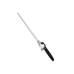
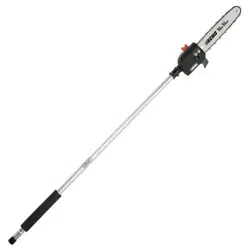
Power Pruner
®
Attachment
FOR MODELS: SRM-2100SB, 2400SB, 210SB, 211SB, 225SB, 260SB,
261SB
PAS-2100, 2400, 2601, 210, 211, 225, 225VP, 225VPB, 230, 231, 260, 261,
265, 266, 280, 2620
DPAS-2100/SB, 2600/SB
Read and understand all provided literature before
use. Failure to do so could result in serious injury.

TABLE OF CONTENTS 99944200532
2 X7702092208
© 03/24 ECHO Inc.
TABLE OF CONTENTS
Introduction ................................................................................................. 3
Servicing Information .................................................................................. 4
Parts and Serial Number...................................................................... 4
Service................................................................................................. 4
ECHO Consumer Product Support...................................................... 4
Product Registration ............................................................................ 4
Additional Literature............................................................................. 4
Safety.......................................................................................................... 5
Manual Safety Symbols and Important Information ............................. 5
International Symbols .......................................................................... 6
Personal Condition and Safety Equipment .......................................... 7
Guide Bar and Saw Chain ................................................................. 11
Kickback ............................................................................................ 12
Equipment.......................................................................................... 13
Description ................................................................................................ 15
Contents.................................................................................................... 16
Assembly................................................................................................... 16
Power Head Shaft to Lower Shaft Assembly ..................................... 16
Support Handle Removal................................................................... 17
Saw Chain Adjustment....................................................................... 18
Operation .................................................................................................. 19
Lubricating the Guide Bar and Saw Chain......................................... 19
Pruning Techniques ........................................................................... 21
Maintenance ............................................................................................. 22
Skill Levels ......................................................................................... 23
Maintenance Intervals........................................................................ 23
Lubrication ......................................................................................... 24
Guide Bar and Saw Chain Replacement ........................................... 25
Guide Bar Cover Cleaning................................................................. 26
Filing Standard Saw Chain ................................................................ 27
Storage ..................................................................................................... 29
Storage Hook Installation................................................................... 29
Specifications............................................................................................ 30
Product Registration.................................................................................. 30
99944200532 INTRODUCTION
X7702092208 3
© 03/24 ECHO Inc.
INTRODUCTION
Specifications, descriptions, and illustrative material in this literature are as
accurate as possible. Specifications are subject to change without notice.
Illustrations might include optional equipment and accessories, and might
not include all standard equipment. Your equipment might appear slightly
different than pictured equipment.
Read and understand all provided literature.
Literature contains specifications and
information for safety, operation,
maintenance, storage, and assembly
specific to this product. Scan QR codes for
more information.
For additional literature, including safety manuals where applicable, or
questions regarding terms used in this manual, visit:
https://www.echo-usa.com/manuals
OR
https://www.shindaiwa-usa.com/manuals
SERVICING INFORMATION 99944200532
4 X7702092208
© 03/24 ECHO Inc.
SERVICING INFORMATION
Parts and Serial Number
Genuine ECHO parts and assemblies
for your ECHO products are available
only from an Authorized ECHO
Dealer. When you do need to buy
parts, always have the model number
and serial number of the unit with you.
For future reference write them in the
space provided below.
Model No. _____________________ Serial No. ____________________
Service
Service of this product during the warranty period must be performed by an
Authorized ECHO Service Dealer. For the name and address of the
Authorized ECHO Service Dealer nearest you, ask your retailer or call:
1-800-432-ECHO (3246). Dealer information is also available on our Web
Site www.echo-usa.com. When presenting your unit for Warranty service/
repairs, proof of purchase is required.
ECHO Consumer Product Support
If you require assistance or have questions concerning the application,
operation, or maintenance of this product, call the ECHO Consumer
Product Support Department at 1-800-432-ECHO (3246) from 8:00 a.m. to
5:00 p.m. (Central Standard Time) Monday through Friday. Before calling,
please know the model and serial number of your unit.
Product Registration
Register your ECHO equipment online at www.echo-usa.com or by filling
out the product registration sheet included in this manual. Registering your
product confirms warranty coverage and provides a direct link to ECHO if
we find it necessary to contact you.
Additional Literature
In addition to finding information online, information is available from your
Authorized ECHO Service Dealer, or by contacting ECHO Incorporated,
400 Oakwood Road, Lake Zurich, IL 60047, 1-800-432-ECHO (3246).
99944200532 SAFETY
X7702092208 5
© 03/24 ECHO Inc.
SAFETY
Manual Safety Symbols and Important Information
Throughout this manual and on the product itself, you will find safety alerts
and helpful, informational messages preceded by symbols or key words.
The following is an explanation of those symbols and key words and what
they mean to you.
The safety alert symbol accompanied by the word “DANGER”
calls attention to an act or condition which WILL lead to serious
personal injury or death if not avoided.
The safety alert symbol accompanied by the word “WARNING”
calls attention to an act or condition which CAN lead to serious
personal injury or death if not avoided.
The safety alert symbol accompanied by the word “CAUTION”
calls attention to an act or condition which might lead to minor
or moderate personal injury if not avoided.
The enclosed message provides information necessary for the
protection of the unit.
Note: This enclosed message provides tips for use, care and
maintenance of the unit.
CIRCLE AND SLASH SYMBOL
This symbol means the specific action shown is prohibited.
Ignoring these prohibitions can result in serious or fatal injury.
SAFETY 99944200532
6 X7702092208
© 03/24 ECHO Inc.
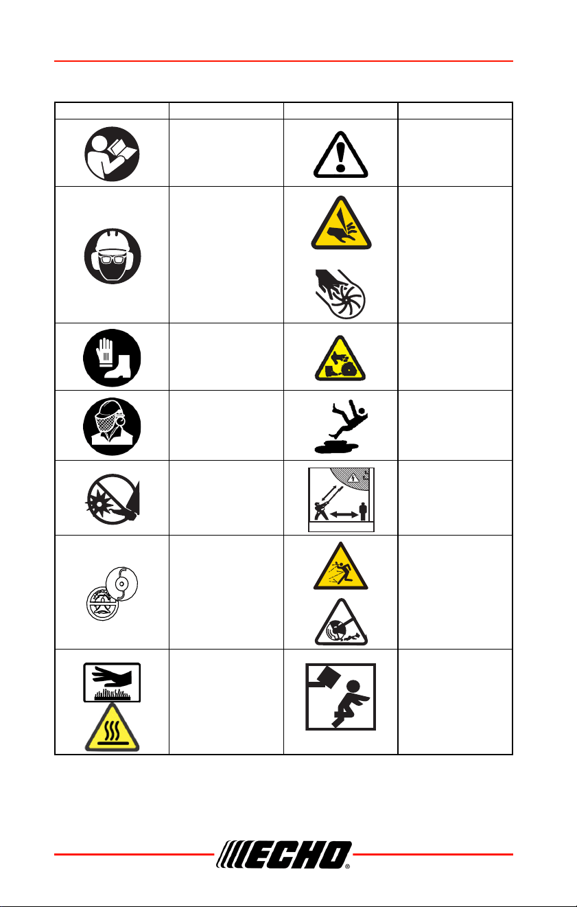
International Symbols
Symbol Description Symbol Description
Warning, see
Operator’s Manual.
Safety / Alert
Wear eye, ear and
head protection.
Finger severing.
Wear hand and foot
protection.
Rotating cutting
attachment.
Wear face shield.
Wear slip-resistant
footwear.
Keep feet away from
blade.
Do not operate closer
than 15 m (50 ft.) from
electrical hazards.
Keep bystanders at
least 15 m (50 ft.)
away.
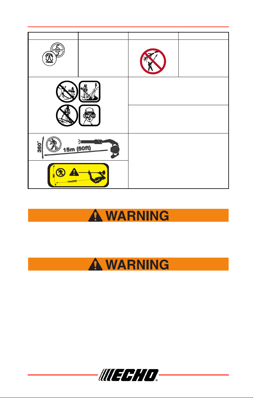
DO NOT USE
BLADES - line head
only.
Beware of thrown
objects.
Hot surface
Plan retreat path from
falling objects.
15 M - 50 FT
99944200532 SAFETY
X7702092208 7
© 03/24 ECHO Inc.
Personal Condition and Safety Equipment
Cancer and Reproductive Harm
www.P65Warnings.ca.gov
Users of this product risk injury to themselves and others if the
unit is used improperly and/or safety precautions are not
followed. Proper clothing and safety gear must be worn when
operating unit.
Physical Condition
Your judgment and physical dexterity may not be good:
• If you are tired or sick
• If you are taking medication
DO NOT USE LINE
HEAD - blades only.
Do not cut branches
overhead.
Keep bystanders and helpers away 15 m
(50 ft.).
Beware thrown objects. Wear eye protection.
Keep bystanders and helpers away 15 m
(50 ft.).
Symbol Description Symbol Description

SAFETY 99944200532
8 X7702092208
© 03/24 ECHO Inc.
• If you have taken alcohol or drugs
Operate unit only if you are physically and mentally well.
Eye Protection
Eye protection that meets ANSI Z87.1 or CE requirements
must be worn whenever you operate the unit.
For additional safety, a full-face shield can be worn over
safety glasses or goggles to provide protection from sharp
branches or flying debris.
Hand Protection
Wear sturdy, no-slip, rubber work gloves to improve your grip on the
handles. Gloves also provide protection against cuts and scratches, cold
environments, and reduce the transmission of machine vibration to your
hands.
Hearing and Ear Protection
ECHO recommends wearing personal protective equipment whenever unit
is used.
Breathing Protection
Operators who are sensitive to dust or other common airborne allergens
may need to wear a dust mask to prevent inhaling these materials while
operating unit. Dust masks can provide protection against dust, plant debris,
and other plant matter such as pollen. Make sure the mask does not impair
your vision, and replace the mask as needed to prevent air restrictions.
Proper Clothing
Wear snug-fitting, durable clothing:
• Pants should have long legs, shirts should have long sleeves.
• DO NOT WEAR SHORTS.
• DO NOT WEAR TIES, SCARVES, JEWELRY, or clothing with loose or
hanging items that could become entangled in moving parts or
surrounding growth.
• Keep clothing buttoned or zipped, and keep shirt tails tucked in.
Wear sturdy work shoes with nonskid rubber soles.
• DO NOT WEAR OPEN TOED SHOES.
99944200532 SAFETY
X7702092208 9
© 03/24 ECHO Inc.
• DO NOT OPERATE UNIT WITH BARE FEET.
Keep long hair away from engine and air intake. Retain hair with cap or net.
Heavy protective clothing can increase operator fatigue, which may lead to
heat stroke. Schedule heavy work for early morning or late afternoon hours
when temperatures are cooler.
The components of this machine generate an electromagnetic
field during operation, which can interfere with some
pacemakers. To reduce the risk of serious or fatal injury,
persons with pacemakers should consult with their physician
and the pacemaker manufacturer before operating this
machine. In the absence of such information, ECHO does not
recommend the use of this machine by anyone who has a
pacemaker.
Extended Operation and Extreme Conditions
Prolonged exposure to cold and/or vibration can result in injury.
Read and follow all safety and operation instructions to
minimize risk of injury. Failure to follow instructions can result
in painful wrist/hand/arm injuries.
It is believed that a condition called Raynaud’s Phenomenon, which affects
the fingers of certain individuals, may be brought about by exposure to
vibration and cold. Exposure to vibration and cold may cause tingling and
burning sensations, followed by loss of color and numbness in the fingers.
The following precautions are strongly recommended, because the
minimum exposure, which might trigger the ailment, is unknown.
• Keep your body warm, especially the head, neck, feet, ankles, hands, and
wrists.
• Maintain good blood circulation by performing vigorous arm exercises
during frequent work breaks, and also by not smoking.
• Limit the hours of operation. Try to fill each day with jobs where operating
the unit or other hand-held power equipment is not required.
• If you experience discomfort, redness, and swelling of the fingers
followed by whitening and loss of feeling, consult your physician before
further exposing yourself to cold and vibration.
SAFETY 99944200532
10 X7702092208
© 03/24 ECHO Inc.
Repetitive Stress Injuries (RSI)
It is believed that overusing the muscles and tendons of the fingers, hands,
arms, and shoulders may cause soreness, swelling, numbness, weakness,
and extreme pain in those areas. Certain repetitive hand activities may put
you at a high risk for developing a Repetitive Stress Injury (RSI). An
extreme RSI condition is Carpal Tunnel Syndrome (CTS), which could occur
when your wrist swells and squeezes a vital nerve that runs through the
area. Some believe that prolonged exposure to vibration may contribute to
CTS. CTS can cause severe pain for months or even years.
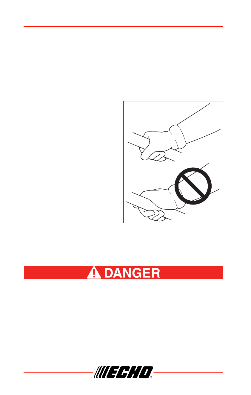
To reduce the risk of RSI/CTS, do
the following
• Avoid using your wrist in a bent,
extended, or twisted position.
Instead try to maintain a straight
wrist position. Also, when
grasping, use your whole hand,
not just the thumb and index
finger.
• Take periodic breaks to minimize
repetition and rest your hands.
• Reduce the speed and force with
which you do the repetitive
movement.
• Do exercises to strengthen the
hand and arm muscles.
• Immediately stop using all power equipment and consult a doctor if you
feel tingling, numbness, or pain in the fingers, hands, wrists, or arms. The
sooner RSI/CTS is diagnosed, the more likely permanent nerve and
muscle damage can be prevented.
All over head electrical conductors and communications wires
can have electricity flow with high voltages. This unit is not
insulated against electrical current. Never touch wires directly
or indirectly, otherwise serious injury or death can result.
99944200532 SAFETY
X7702092208 11
© 03/24 ECHO Inc.
Guide Bar and Saw Chain
Serious injury may result from the use of non approved
guide bar and saw chain combinations. Read and comply
with all safety instructions listed in this manual.
ECHO, INC. will not be responsible for the failure of cutting
devices or accessories which have not been tested and
approved by ECHO for use with this unit.
• Never adjust the guide bar or saw chain when the engine is operating.
• Check that the cutting attachment, guide bar and saw chain is firmly
attached and in safe operating condition.
• Only use ECHO approved guide bar and saw chain.
• Do not hit rocks, stones, tree
stumps and other foreign objects
with the saw chain.
• Do not cut into the ground with
the saw chain.
• If saw chain strikes an
obstruction, stop engine
immediately and inspect saw
chain for damage.
• Do not operate with a dull, broken or discolored saw chain.
• Remove all foreign objects from work area.
• Always cover the guide bar and saw chain with guide bar cover during
transportation and in storage.
Read the Manuals
• Provide all users of this equipment with the Operator’s Manual for
instructions on Safe Operation.
Clear the Work Area
• Spectators and fellow workers must be warned, and children and animals
prevented from coming nearer than 15 m (50 ft.) while the unit is in use.
Use Proper Clothing & Equipment
• Always wear head protection with full face shield to help protect against
falling branches and debris.
SAFETY 99944200532
12 X7702092208
© 03/24 ECHO Inc.
Keep a Firm Grip
• Always hold throttle handle and support handle with thumbs and fingers
tightly encircling the handles.
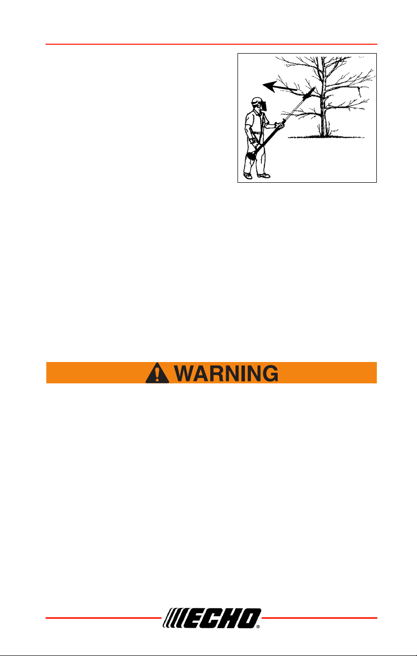
Keep a Solid Stance
• Maintain footing and balance at all times. Do not stand on slippery,
uneven or unstable surfaces. Do not work in odd positions or on ladders.
Do not over reach.
• Operate the pole pruner only from the ground or out of an approved
bucket lift.
• Always evaluate the branches to be pruned for hazards such as loose
dead branches which may fall and strike the operator or helpers. Remove
hazards before pruning.
• Plan retreat path from falling objects.
• Cut branches bounce when striking ground.
• Check that shoulder harness is adjusted for safe, comfortable operation.
• Turn the pole pruner off when moving from tree to tree.
• Avoid any contact with saw chain..
Avoid Hot Surfaces
• Keep exhaust area clear of flammable debris. Avoid
contact during and immediately after operation.
Kickback
Kickback can lead to dangerous loss of control of the pole
pruner and result in serious injury to the operator or any one
standing close by. Hold the pole pruner firmly with both hands
with thumbs and fingers encircling the front and rear handles.
Be aware of the down and outward path the pruner will take after
the cut is made.
99944200532 SAFETY
X7702092208 13
© 03/24 ECHO Inc.
Kickback may occur when the moving
saw chain at the nose or tip of the guide
bar touches an object, or when the wood
closes in and pinches the saw chain in the
cut. In some cases this may cause a
lightning-fast reverse action, kicking the
guide bar and saw chain up and back or
down and back towards the operator.
Either of these reactions may cause the
operator to lose control of the pole pruner
which could result in serious personal
injury.
With a basic understanding of kickback, you can reduce or eliminate the
element of surprise which contributes to accidents.
Avoid contact of the guide bar tip with any object while the saw chain is
moving.
Cut only wood. Avoid striking concrete, metal, wire, or other obstructions
which could cause kickback or damage to the saw chain.
If the saw chain does strike a foreign object, immediately stop the engine,
inspect and repair the pole pruner if necessary.
Equipment
Use this attachment with ECHO approved models only. Serious
injury may result from the use of this attachment combined with
a non approved ECHO product.
Check unit for loose/missing nuts, bolts, and screws.
Tighten and/or replace as needed.
Inspect ProPaddle sweeper drums for damage and that
they are firmly secured in place. Replace paddles of
damaged or worn excessively.
Check that the ProPaddle attachment is firmly attached and
in safe operating condition.
Note: ECHO, INC. will not be responsible for the failure of cutting
devices, attachments or accessories which have not been
tested and approved by ECHO.

SAFETY 99944200532
14 X7702092208
© 03/24 ECHO Inc.
Moving parts can amputate fingers or cause severe injuries.
Keep hands, clothing and loose objects away from all openings.
ALWAYS stop engine, disconnect spark plug, and make
sure all moving parts have come to a complete stop before
removing obstructions, clearing debris, or servicing unit.
DO NOT start or operate unit unless all guards and
protective covers are properly assembled to unit.
NEVER reach into any opening while the engine is running.
Moving parts may not be visible through openings.
99944200532 DESCRIPTION
X7702092208 15
© 03/24 ECHO Inc.
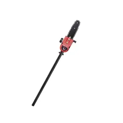
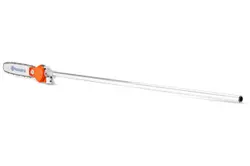
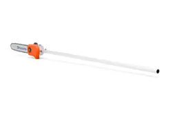
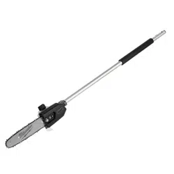
DESCRIPTION
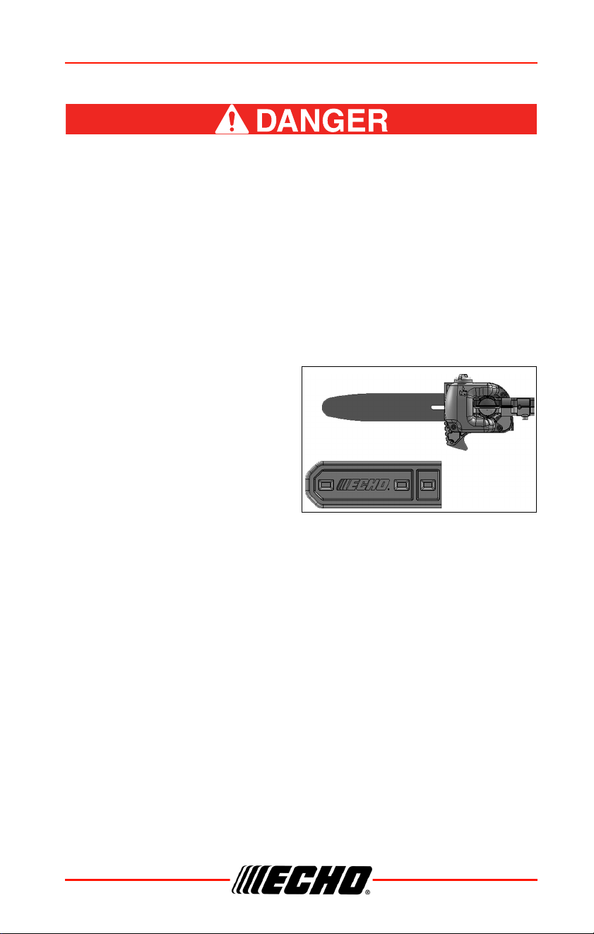
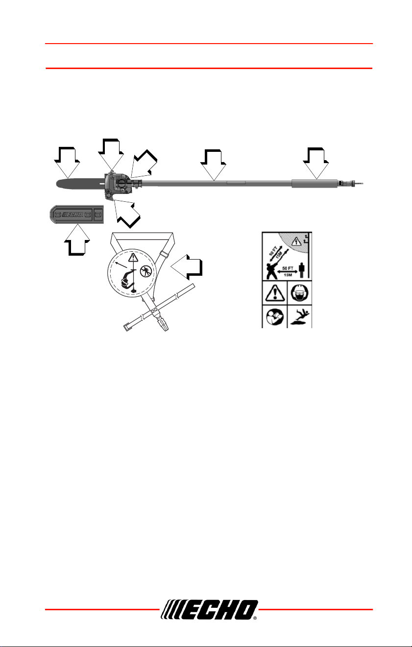
Locate the safety decal(s) or etching(s) on your unit. Make sure they are
legible, and that you understand and follow the instructions. If any cannot be
read, replacements can be ordered from your ECHO dealer. Images shown
below are for example only. Those on your unit might appear slightly
different.
1. Support handle - for left hand
2. Lower drive shaft assembly
3. Cutting attachment
4. Automatic oiler assembly
5. Saw chain
6. Guide bar
7. Cutting shoe
8. Shoulder harness
9. Guide bar cover
15 m
50 ft
1
8
9
2
3
4
5,6
7

CONTENTS 99944200532
16 X7702092208
© 03/24 ECHO Inc.
CONTENTS
The ECHO product you purchased has been factory pre-assembled for your
convenience. Due to packaging restrictions, some assembly may be
necessary.
After opening the carton, check for damage. Immediately notify your retailer
or ECHO Dealer of damaged or missing parts. Use the contents list to check
for missing parts.
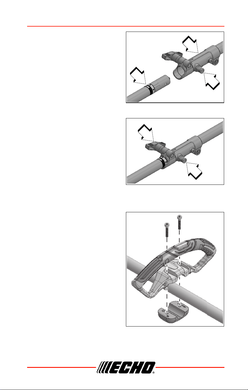
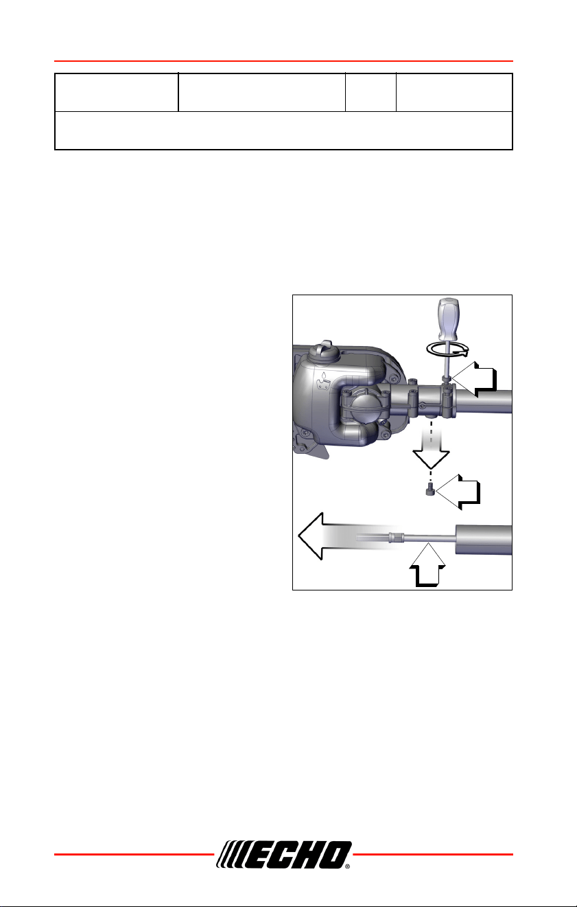
ASSEMBLY
Power Head Shaft to Lower Shaft Assembly
Do not perform maintenance or assembly procedures with unit
running.
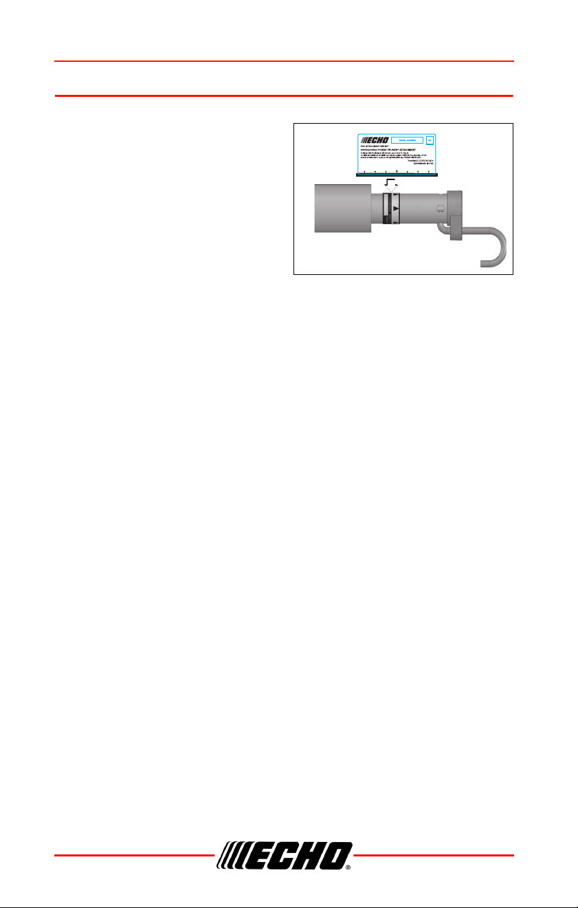
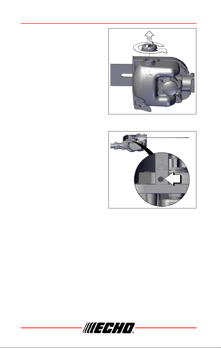
1. Set Power Head/Shaft Assembly on a level surface.
2. Pull locater pin (A) out, and turn counterclockwise one-quarter turn to
lock-out position.
3. Remove storage hook and cap from attachment drive shaft.
Note: Your coupler may appear different than coupler shown.
Earlier model power heads may have shorter couplers.
1
Power Pruner
®
Attachment
1 Guide Bar Cover
1 Shoulder Harness
1 Storage Hook Assembly
1 Operator’s Manual
1 Warranty Statement
99944200532 ASSEMBLY
X7702092208 17
© 03/24 ECHO Inc.
4. Carefully fit attachment drive
shaft assembly into coupler (B).
Rotate the shaft (C) to make
sure the inner lower drive shaft
engages the square upper drive
shaft socket.
Note: Lower bearing housing
and head assembly must
be in line with the engine.
Note: Some models have an
assembly line decal to
assist in assembly.
5. Rotate locater pin (A) one-
quarter turn clockwise to
engage lower shaft hole. Make
sure locater pin is fully engaged
by rotating the lower drive shaft.
Locater pin should snap flush in
coupler. Full engagement will
prevent further shaft rotation.
6. Secure lower shaft assembly to
coupler by tightening clamping
knob (D).
Support Handle Removal
Note: Support handles or
support handles with
barrier bars are not
recommended for use
with this attachment.
1. Remove support handle
assembly, barrier bar (if
installed), and mounting
hardware from PAS or SRM-SB
power head.
2. Retain parts for future use.
B
A
C
D
A
ASSEMBLY 99944200532
18 X7702092208
© 03/24 ECHO Inc.
Saw Chain Adjustment
Always disconnect spark plug wire or remove battery before
servicing cutting attachment. Wear gloves when handling saw
chain, otherwise serious personal injury may result.
Saw Chain Adjustment
1. Stop unit.
2. Disconnect spark plug lead or
remove battery.
3. Loosen two guide bar nuts (A)
until finger tight.
Always loosen guide bar nuts before turning the chain tension
adjuster, otherwise the clutch cover and tensioner will be damaged.
4. Hold the bar nose up, and turn the adjuster screw (B) clockwise until
the chain fits snugly against the underside of the bar, as shown. Cold
Chain Only - turn adjuster screw CW an additional 1/8 - 1/4 turn.
Tighten both guide bar nuts with nose held up. Tighten rear nut first..
5. Pull the chain around the guide bar by hand. Reduce the chain tension
if you feel tight spots.
6. When chain is properly tensioned, tighten guide bar nuts securely.
Tighten guide bar nuts to 8 - 9 N•m (71 - 80 in. lbs.). DO NOT over-
tighten nuts or damage may result.
A
B
99944200532 OPERATION
X7702092208 19
© 03/24 ECHO Inc.
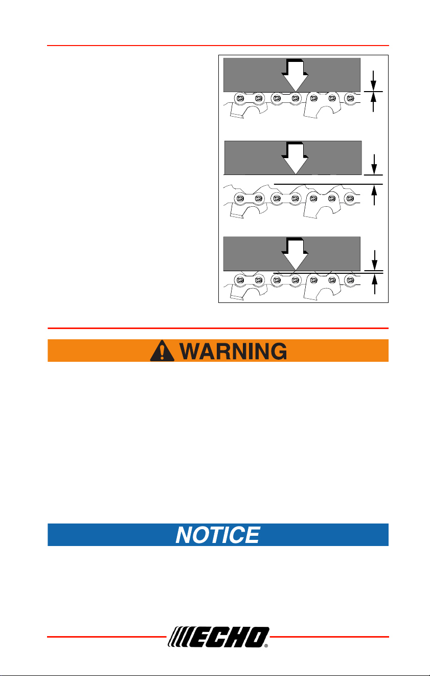
7. Keep chain properly tensioned
at all times.
(A) - Correct cold tension. The
side link contacts the guide bar.
(B) - Chain needs tensioning.
(C) - Correct warm tension. A
distance of 1/8 in. (3 mm)
between side link and guide bar
at bottom
Note: All chains require
frequent adjustment.
8. Connect spark plug lead.
OPERATION
Moving parts can amputate fingers or cause severe injuries.
Keep hands, clothing and loose objects away from all openings.
Always stop unit, disconnect spark plug or remove battery, and
make sure all moving parts have come to a complete stop
before removing obstructions, clearing debris, or servicing unit.
Note: Refer to your PAS power source Operator's Manuals for
starting and stopping instructions.
Lubricating the Guide Bar and Saw Chain
Automatic Oiling System
To prevent plastic deterioration, do not use synthetic or silicone
based oil.
A
B
C
OPERATION 99944200532
20 X7702092208
© 03/24 ECHO Inc.
1. Wipe debris from around oil fill
cap.
2. Remove oil fill cap and fill
reservoir with a quality, low
viscosity guide bar and saw
chain oil.
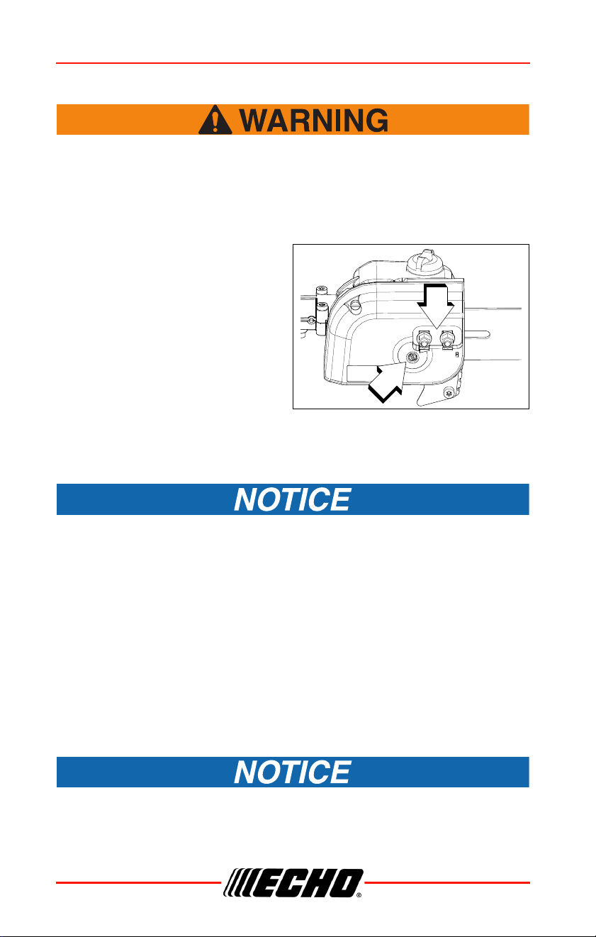
Adjusting Automatic Oiler
1. From bottom of gear case, turn
adjustment screw (A) clockwise
to decrease oil volume, or
counterclockwise to increase oil
volume.
Note: The automatic oiler is
preset to deliver a
sufficient oil discharge
volume during normal
operating conditions.
During heavy or dry
cutting conditions, the oil
discharge volume may be
increased to assure
adequate lubrication. If oil is leaking from the bar cover area,
reduce the oil discharge volume. Refill the oil reservoir with
each tank of fuel.
Note: Very little visible oil on the saw chain will provide sufficient
lubrication.
A
99944200532 OPERATION
X7702092208 21
© 03/24 ECHO Inc.
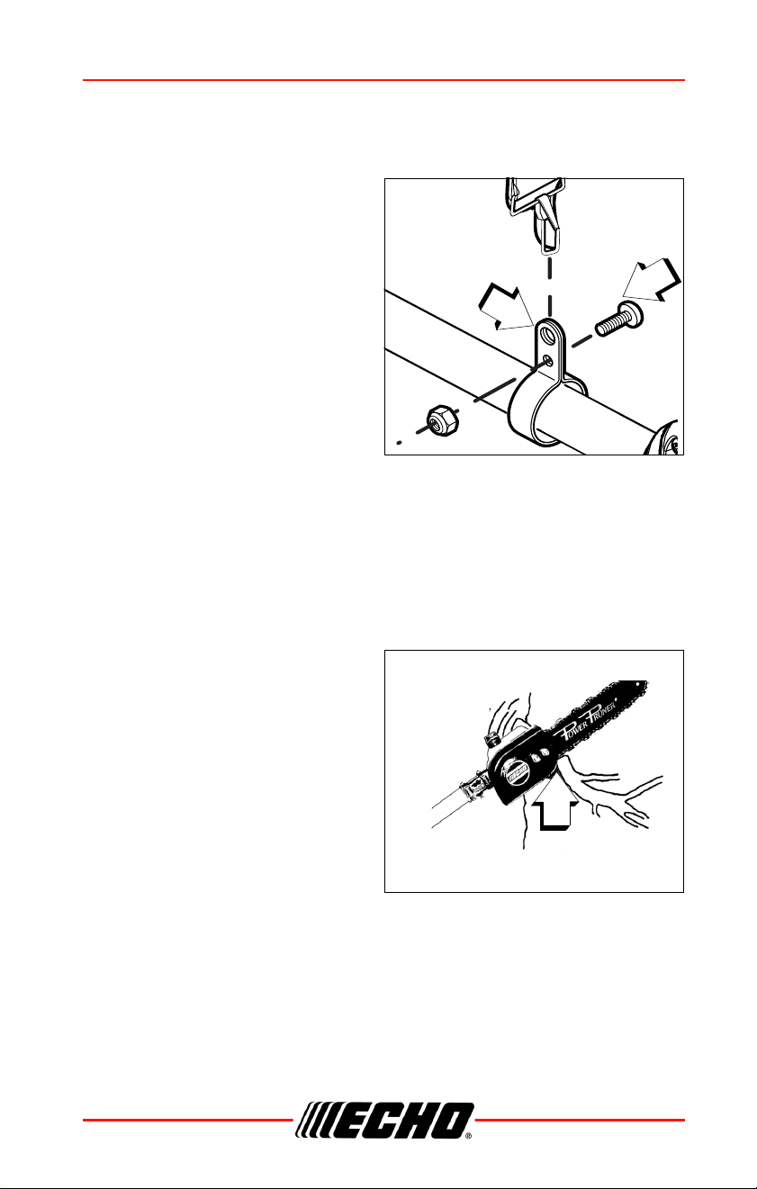
Pruning Techniques
Shoulder Harness (if included)
1. Loosen the harness clamp bolt
(A).
2. Put the harness on and attach it
to the clamp ring (B).
3. Adjust harness for comfortable
operation.
4. Tighten harness clamp bolt (A).
The pole pruner attachment is
designed for light to medium
trimming of limbs and branches up
to 203 mm (8 in.) diameter. Follow
these tips for successful operation.
• Plan cut carefully. Check direction
branch will fall.
• Plan retreat path from falling branch. Cut branches bounce when striking
ground.
• Long branches should be removed in several pieces.
• Do not stand directly beneath branch being cut.
• When ready to cut, hold the
cutting shoe against the branch.
This will prevent whipping of the
branch. DO NOT use back and
forth sawing action.
A
B
Cutting shoe against branch
Correct
MAINTENANCE 99944200532
22 X7702092208
© 03/24 ECHO Inc.
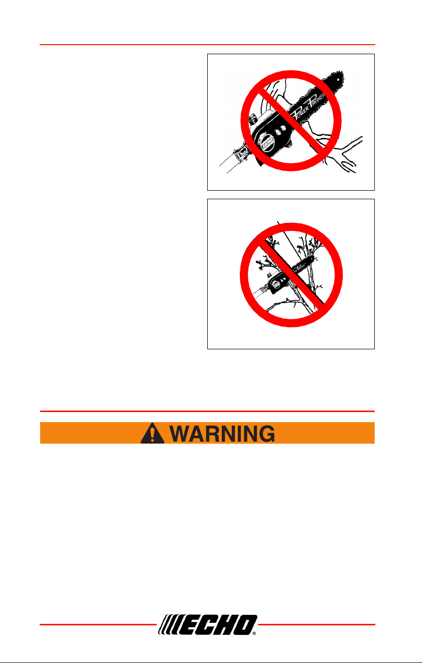
• Look out for branches
immediately behind the branch
being cut. If saw chain hits a rear
branch damage to the saw chain
and guide bar may occur.
• Accelerate to full speed.
• Ease cutting pressure when
nearing end of cut to maintain
control.
• When pruning a limb 102 mm
(4 in.) diameter or larger cut as
follows:
1. Under cut 1/4 limb diameter
near tree trunk.
2. Finish top cut slightly farther
out on limb.
3. Flush cut stub at trunk.
• DO NOT use for felling or
bucking.
MAINTENANCE
Moving parts can amputate fingers or cause severe injuries.
Keep hands, clothing and loose objects away from all openings.
Always stop unit, disconnect spark plug or remove battery, and
make sure all moving parts have come to a complete stop
before removing obstructions, clearing debris, or servicing unit.
Allow the unit to cool before performing maintenance or
adjustments. Wear gloves to protect hands from sharp edges
and hot surfaces.
Cutting shoe away from branch
Not Correct
Blade hits rear branch
Not Correct
99944200532 MAINTENANCE
X7702092208 23
© 03/24 ECHO Inc.
Operating a poorly maintained unit can result in serious injuries
to operator or bystanders. Always follow all maintenance
instructions as written, otherwise serious personal injury can
result.
Your unit is designed to provide many hours of trouble free service. Regular
scheduled maintenance will help your unit achieve that goal. If you are
unsure or are not equipped with the necessary tools, we recommend that
you take your unit to a Servicing Dealer for maintenance. To help you
decide whether you want to do it yourself or have the Dealer do it, each
maintenance task has been graded. If the task is not listed, see your Dealer
for repairs.
The use of emission control components other than those specifically
designed for this unit is a violation of federal law.
Skill Levels
Level 1 = Easy to do. Common tools may be required.
Level 2 = Moderate difficulty. Some specialized tools may be required.
Level 3 = See your dealer.
Click HERE or go to http://www.echo-usa.com/products/maintenance-kit
or
HERE https://www.shindaiwa-usa.com/you-can.aspx
Maintenance Intervals
Component Maintenance Procedure
Skill
Level
Interval
Drive Shaft
Apply lithium based
grease.
1
Every 25 hours
of use.
Guide Bar Inspect/Clean/Lubricate
2
Before each use.
Saw Chain
Inspect/Sharpen/
Replace/Tension
Screws/Nuts/
Bolts
Inspect/Tighten/Replace 1
MAINTENANCE 99944200532
24 X7702092208
© 03/24 ECHO Inc.
Lubrication
Drive Shaft
Level 1.
1. Remove cutting attachment
locater screw (A).
2. Loosen two bolts (B).
3. Remove cutting attachment
assembly.
4. Remove flex cable (C), wipe
clean and apply 15 ml (0.5 oz.) of
lithium based grease.
5. Slide the flexible cable back in
the drive housing. DO NOT get
dirt on the flex cable.
6. Install and secure cutting
attachment assembly.
IMPORTANT - Time intervals shown are maximum. Actual use and your
experience will determine the frequency of required maintenance.
Parts Required: Lithium Based Grease
Component Maintenance Procedure
Skill
Level
Interval
A
B
C
99944200532 MAINTENANCE
X7702092208 25
© 03/24 ECHO Inc.
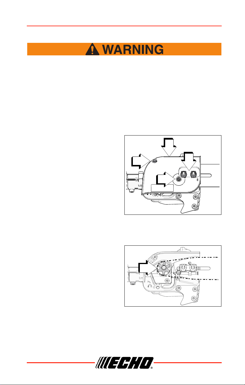
Guide Bar and Saw Chain Replacement
Never try to replace or adjust guide bar and saw chain with
engine running. Always disconnect spark plug wire or remove
battery before servicing guide bar and saw chain. This saw
chain is VERY sharp, wear heavy gloves to protect your hands
when handling it. Wear eye protection meeting CE or ANSI
specification Z87.1.
Guide Bar Replacement
Level 2.
1. Remove two guide bar nuts (A)
and guide bar cover screw (B),
turn saw chain tension
adjustment screw (C)
counterclockwise to release
tension.
2. Remove guide bar cover (D).
3. Remove guide bar and saw
chain from gear case and
sprocket.
4. Remove chain from guide bar
and check guide bar for
damage and excessive or uneven wear. Replace guide bar if necessary
5. Install chain on guide bar with cutters on top of bar facing toward bar
tip.
6. Install guide bar and chain on
gear case, engaging chain with
drive sprocket (E).
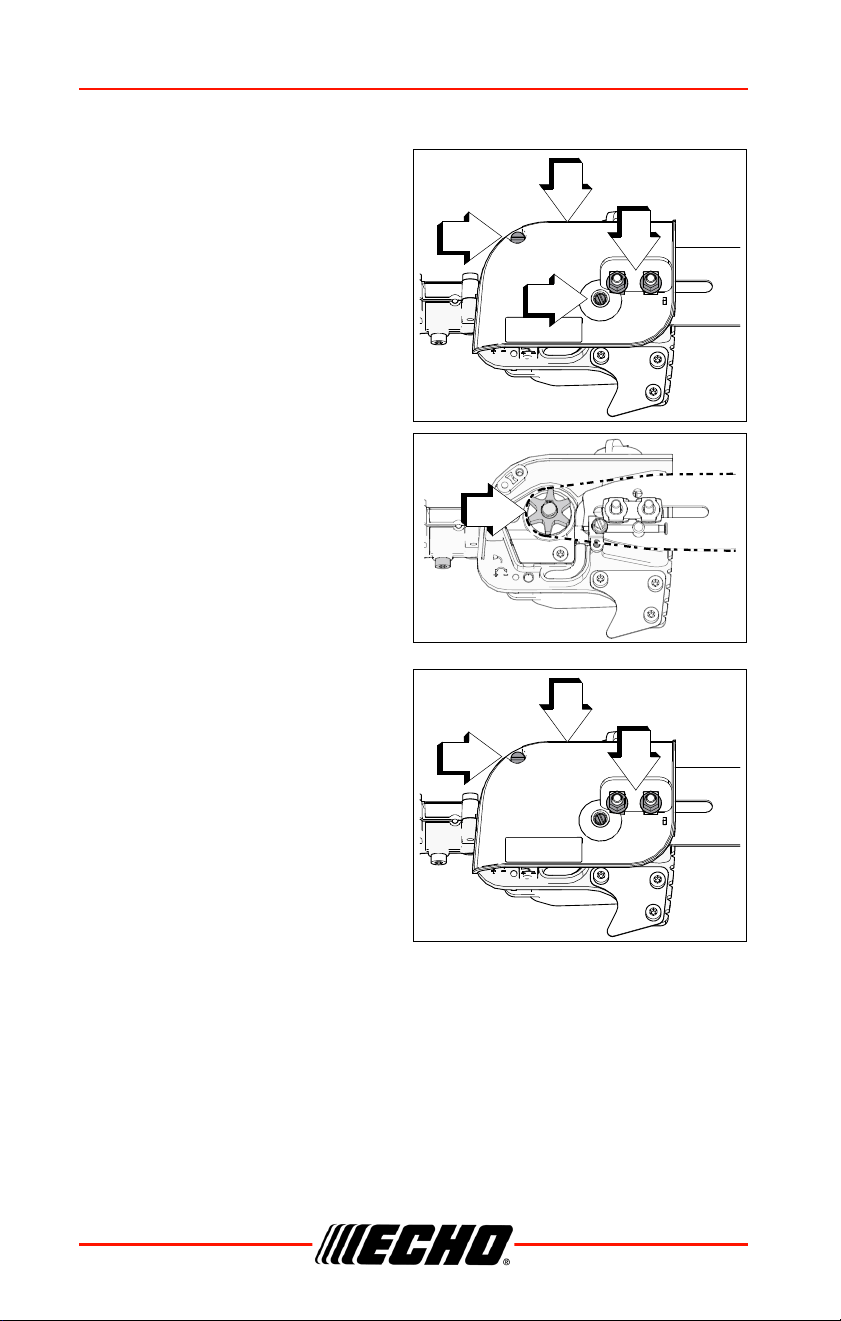
7. Turn tension adjustment screw
(C) clockwise to take up slack
in saw chain.
8. Install guide bar cover (D), and
tighten guide bar nuts finger
tight and install guide bar cover
screw (B).
9. Adjust chain tension.
A
B
C
D
E
MAINTENANCE 99944200532
26 X7702092208
© 03/24 ECHO Inc.
Guide Bar Cover Cleaning
1. Remove two guide bar nuts (A)
and guide bar cover screw (B).
2. Remove guide bar cover (D).
3. Gently brush debris from inside
guide bar cover and from
around sprocket.
4. Hold the bar nose up. Install
guide bar cover (D). Install the
guide bar nuts (A). Tighten the
rear nut first, then tighten the
front nut. Install and tighten the
guide bar cover screw (B)
AB
C
D
AB
D
99944200532 MAINTENANCE
X7702092208 27
© 03/24 ECHO Inc.
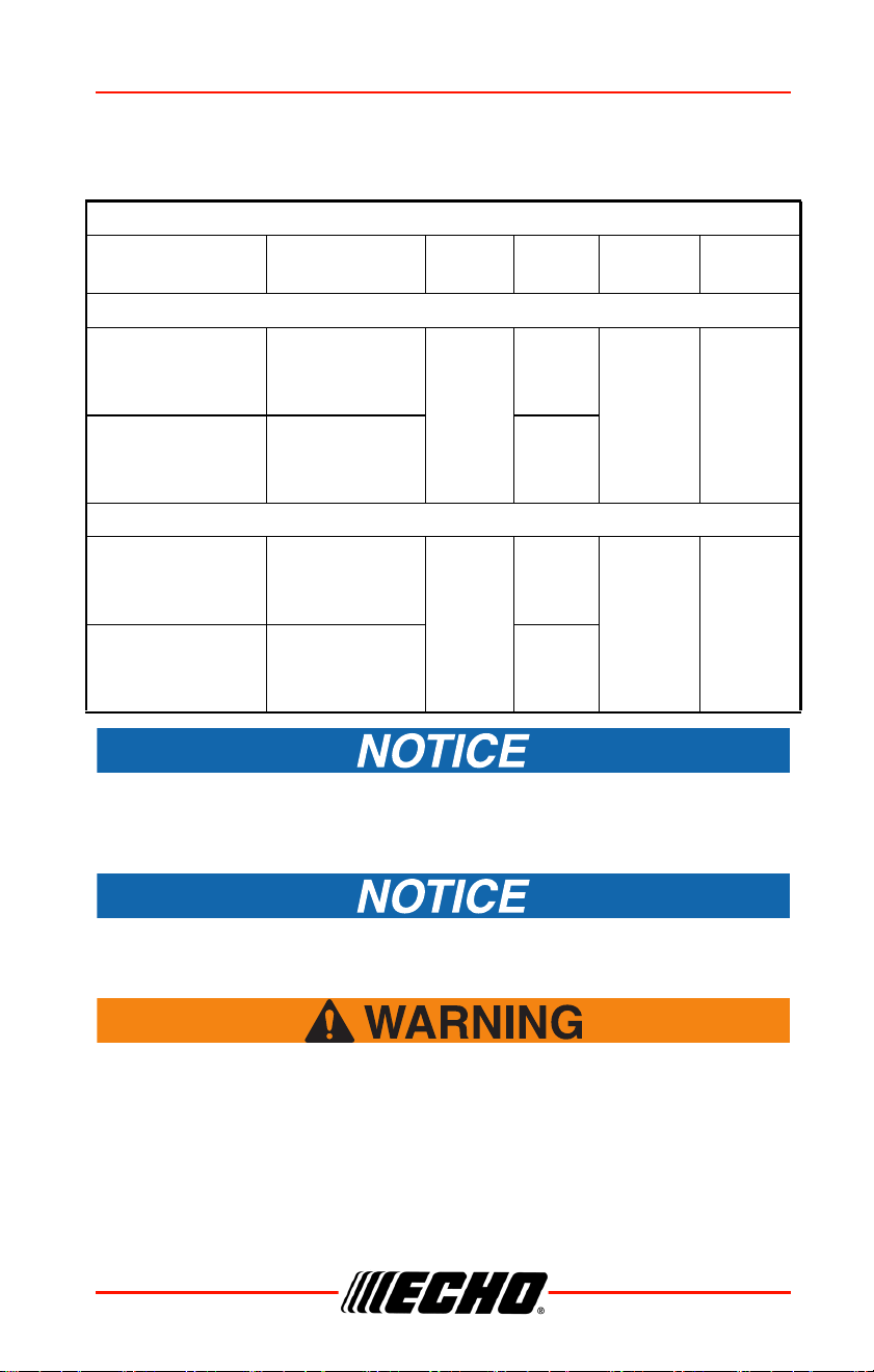
Filing Standard Saw Chain
Level 2
Check bar part number on your Power Pruner. Chain and guide bar
gauge size must be identical. Use bar and chain combinations shown
in table above.
Dull or damaged cutters will result in poor cutting performance,
increased vibration, and premature saw chain failure.
Always stop unit and disconnect spark plug wire, or remove
battery before servicing guide bar and saw chain. Always wear
gloves when filing saw chain, otherwise serious personal injury
may result.
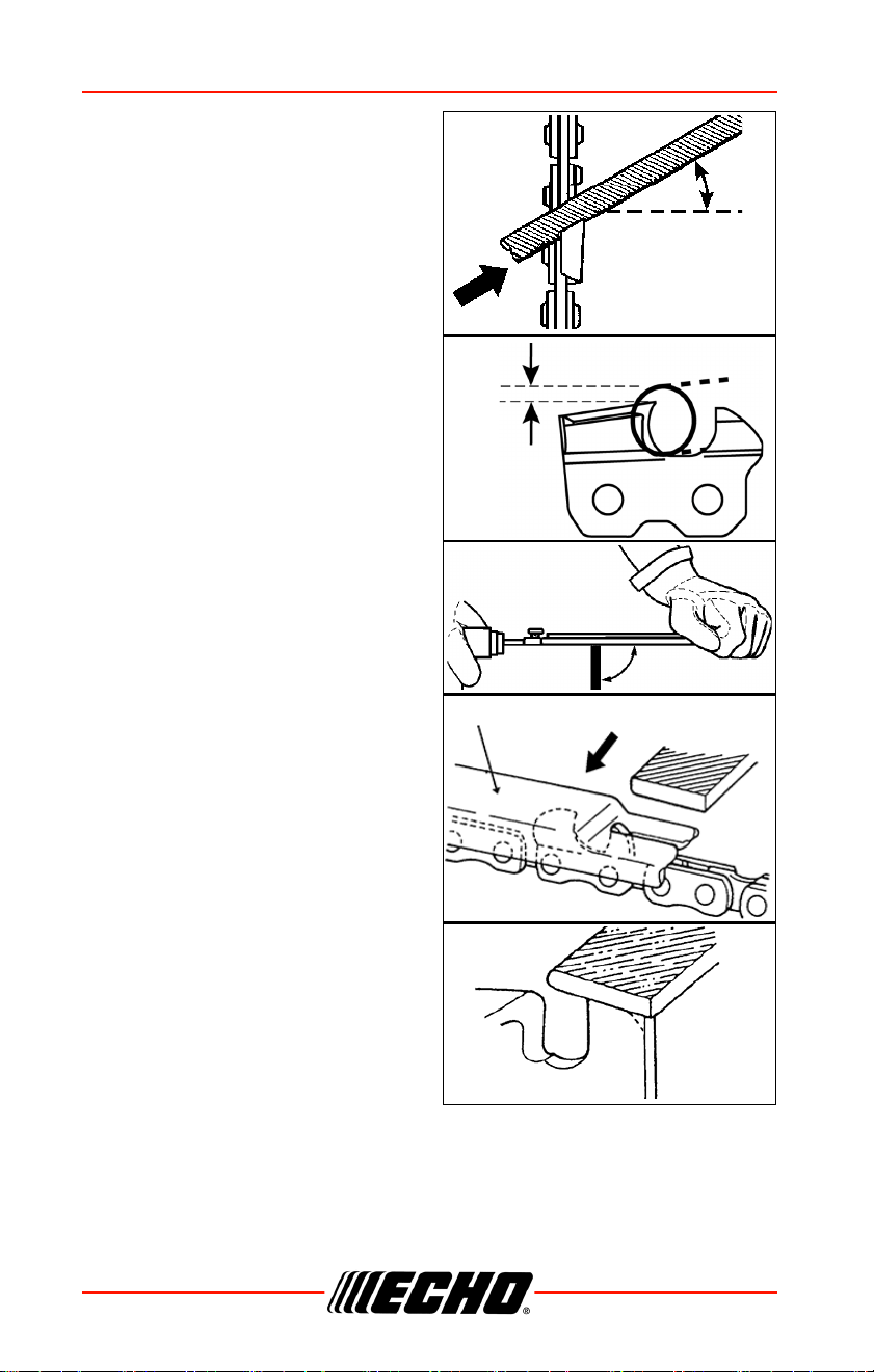
1. Use a 4.5 mm round file for a 0.043 in. gauge saw chain. Use a
5/32 in. round file for 0.050 in. gauge saw chain.
Power Pruner
®
Bar and Chain Combinations
BAR P/N CHAIN P/N
CHAIN
TYPE
LINKS PITCH GAUGE
Narrow Kerf
254 mm (10 in.)
narrow bar
P/N
10A4CD3739
90PX39CQ
90
39
0.375
in.
0.043
in.
305 mm (12 in.)
narrow bar
P/N
12A4CD3744
90PX44CQ 44
Regular
254 mm (10 in.)
regular bar
P/N
10A0CD3739
91VXL39CQ
91
39
0.375
in.
0.050
in.
305 mm (12 in.)
regular bar
P/N
12A0CD3744
91VXL44CQ 44
MAINTENANCE 99944200532
28 X7702092208
© 03/24 ECHO Inc.
2. Set round file in cutter at 30°
angle. One fifth (1/5) of the file
should be exposed above top
cutter edge.
3. Keep file horizontal in cutter and
file in one direction.
4. File until cutter top and side
bevel edges are sharp without
nicks.
5. Place depth gauge tool firmly on
top of cutter with 0.635 mm
(0.025 in.) slot and end against
front cutter raker. File cutter raker
with flat file until flush with top of
depth gauge.
6. Finish cutter sharpening by
rounding front raker edge with
flat file.
30°
Keep this angle
1/5
90°
Depth gauge tool
99944200532 STORAGE
X7702092208 29
© 03/24 ECHO Inc.
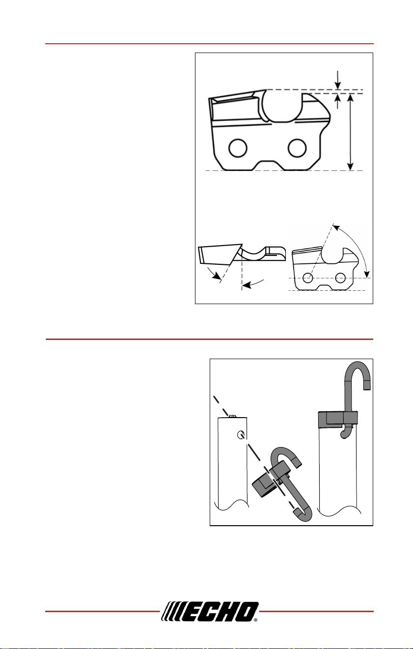
7. Properly filed cutter is as
shown.
8. Apply clean oil and rotate
saw chain slowly to wash
away filings.
9. If saw chain is coated or
clogged with resin, clean in
kerosene, then soak in oil.
STORAGE
Storage Hook Installation
1. Insert small end of hook into
locating hole on attachment
shaft.
2. Slide plastic cap onto end of
attachment shaft.
75° (90PX)
Side plate angle
30°
Top plate filing angle
0.64 mm (0.025 in.)
Parallel
Depth gauge
80° (91VXL)

SPECIFICATIONS 99944200532
30 X7702092208
© 03/24 ECHO Inc.
SPECIFICATIONS
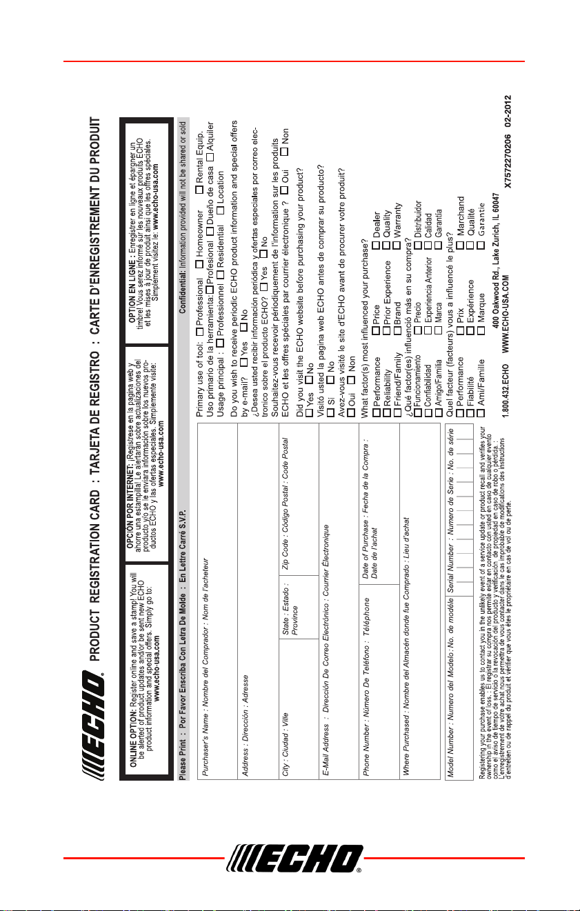
PRODUCT REGISTRATION
Thank you for choosing ECHO Power Equipment
Please go to http://www.echo-usa.com/Warranty/Register-Your-ECHO to
register your new product on-line. It's FAST and EASY! NOTE: your
information will never be sold or misused by ECHO, Incorporated.
Registering your purchase enables us to contact you in the unlikely event of
a service update or product recall, and verifies your ownership for warranty
consideration.
If you do not have access to the Internet, you can complete the form below
and mail to:
ECHO Incorporated, Product Registration, PO Box 1139,
Lake Zurich, IL 60047.
MODEL 99944200532
Length 1451 mm (57.1 in.)
Width 105 mm (4.1 in.)
Height 147 mm (5.8 in.)
Weight 2.25 kg (4.96 lbs.)
Drive Shaft Assembly
6.35 mm (0.25 in.) flexible shaft
Rotation Direction Counter-clockwise
Gear Case Ratio 1.5:1
Handle Foamed rubber grip
Oiling System Automatic, 225 ml (7.6 oz.) capacity
Sprocket Type 6 tooth spur, 9.53 mm (0.375 in.) pitch
Guide Bar
1.3 mm (0.050 in.) gauge; sprocket nose 254 mm
(10 in.); 9.53 mm (0.375) pitch
Chain Oregon Chain 91VXL-39E
99944200532 PRODUCT REGISTRATION
X7702092208 31
© 03/24 ECHO Inc.
ECHO Incorporated