
Technical Support and E-Warranty Certificate
www.vevor.com/support
Pressure Test Pump Instructions
MODEL: SYB-25
We continue to be committed to provide you tools with competitive price.
"Save Half", "Half Price" or any other similar expressions used by us only represents an
estimate of savings you might benefit from buying certain tools with us compared to the major
top brands and does not necessarily mean to cover all categories of tools offered by us. You
are kindly reminded to verify carefully when you are placing an order with us if you are
actually saving half in comparison with the top major brands.

- 1 -
MODEL: SYB-25
Have product questions? Need technical support? Please feel free to
contact us:
Technical Support and E-Warranty Certificate
www.vevor.com/support
NEED HELP? CONTACT US!
This is the original instruction, please read all manual instructions
carefully before operating. VEVOR reserves a clear interpretation of our
user manual. The appearance of the product shall be subject to the
product you received. Please forgive us that we won't inform you again if
there are any technology or software updates on our product.
Pressure Test Pump

- 2 -
Warning-To reduce the risk of injury, user must read
instructions manual carefully.
PRODUCT PRESENTATION
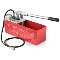
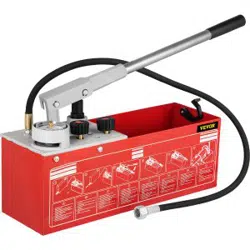
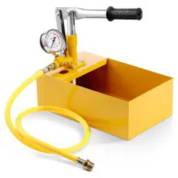
Manual pressure test pump is composed of pump body, plunger,
sealing ring, control valve, pressure gauge, water tank and so on.
Working principle: The plunger is lifted up by the handle to create a
vacuum in the pump body, and the inlet valve is opened. The liquid
enters the pump body through the filter screen and water pipe. When
the handle applies force to press down, the inlet valve is closed, the
outlet valve is opened, the pressure water is output, and the water
enters the detected object. The work is carried out in such a cycle to
realize the pressure test of the rated pressure.
Special attention:
Do not use in workplaces with acid, alkali and corrosive substances.
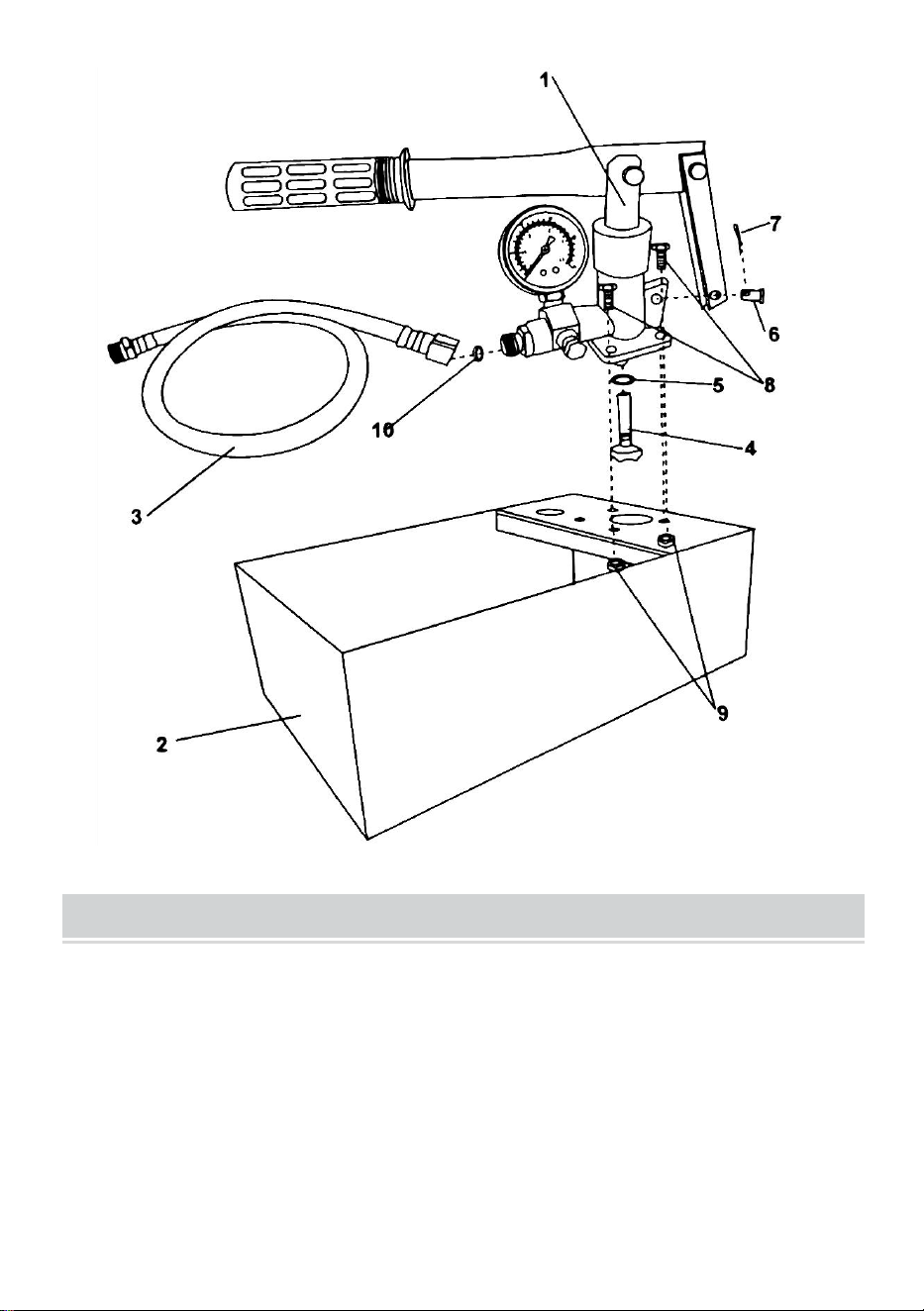
INSTALLATION STEPS
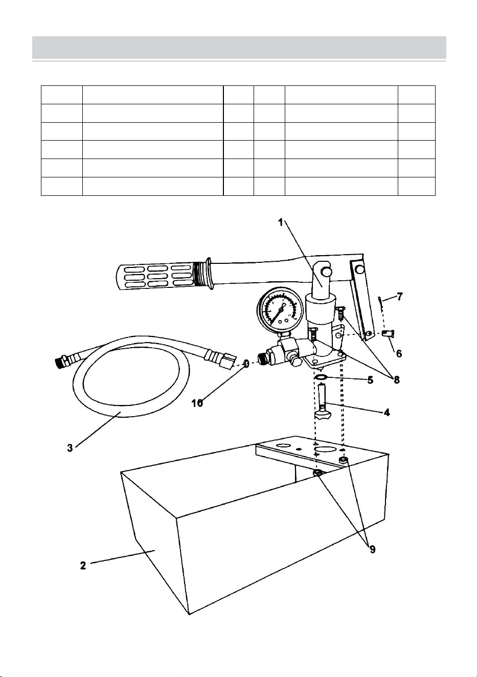
1. Align the handle hole with the pump body hole, insert the pin into the
handle hole, then insert the pin into the pin hole and bend the pin (see
explosion numbers 6 and 7 for details).
2. Place the pump body on the tank, with the handle facing the water tank.
Align the screw holes of the pump body with those of the water tank, place
the four bolts into the screw holes and tighten them with a tool. (see
explosion numbers 8 and 9 for details).
3. Install the suction pipe from the inside of the water tank on the interface
at the bottom of the pump body (see explosion diagram No. 4).
Put the Sealing ring in the joint of the water pipe, and then tighten the joint
of the water pipe and the pump body (see explosion diagram No. 10).
- 3 -
EXPLOSION DIAGRAM AND PARTS LIST
No.
DESCRIPTION
Qty
No.
DESCRIPTION
Qty
1
Press handle with meter
1
6
Support pin
1
2
Water tank
1
7
R-snap
1
3
Hose with connector
1
8
Bolt
4
4
Strainer
1
9
Screw nut
4
5
O-ring
2
10
Sealing ring
2
- 4 -
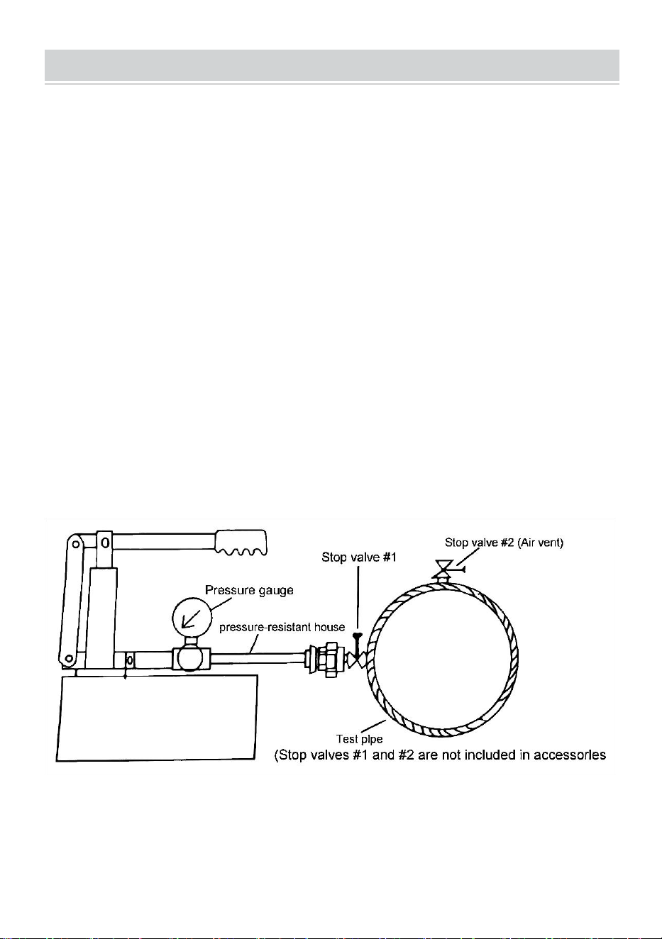
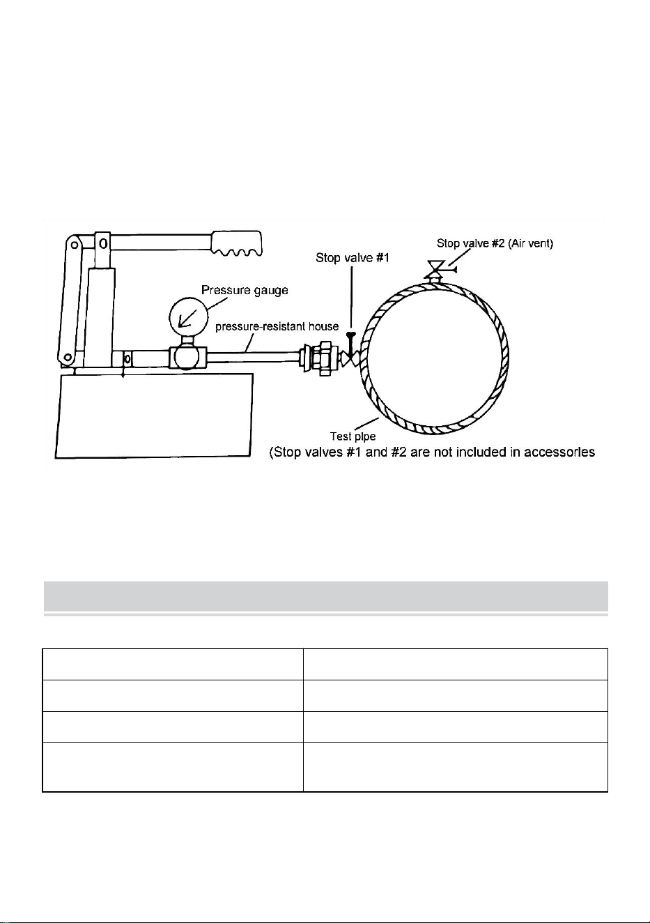
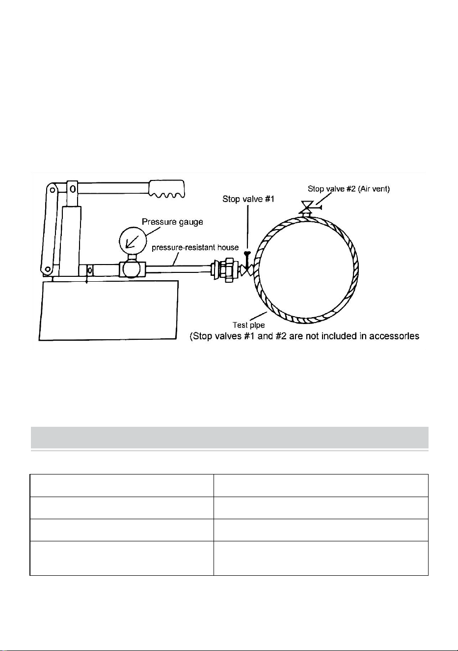
TESTING PROCEDURES
1. Install the stop valves to the test pipe(#1,#2)
2. Fill up the test pipe with water by the use of service water of other
supply source.
3. When the test pipe is filled with water, remove air and close the
valve(#2).
4. Connect the tester and the test pipe with the attached
pressure-resistant house assay
5. Fill the water tank of the tester with water and operate the pump.
6. Open the stop valve(#1) of the test pipe and continue the
operation to fill up with water.
7. When the pressure gauge equipped to the tester rises to the
required pressure,stop operating the pump.
8. If the pressure does not drop, the test pipe is perfect。
9. If the pressure drops, it is indicative of leakage caused
somewhere on the test pipe.

- 5 -
PERFORMANCE PARAMETER
Model
SYB-25
Tank capacity
1.4 gallon
Pressure test range
0-25 bar
Hose specification
Pressure resistant hose with ½ inch
external threaded connector
FAILURE RECOVERY
When the handle
moves upward, the
water cannot be
sucked up.
1. Check whether the suction pipe is blocked by
garbage.
2. Check whether the switch is tightened.
The handle is weak
when moving up
and down.
1. Check whether the switch is tightened.
2. Check whether the sealing ring of the piston
shaft is damaged.
3. Check whether the check valve in the outlet joint
is unclean.
The pressure
gauge shows that
the pressure is
unstable.
1. If there is leakage in the pipeline or outlet joint,
the sealing ring should be replaced.
2. the meter rod connection leakage, replace the
sealing country.
3. pressure gauge damage, repair pressure gauge.
Special attention:
Do not use in workplaces with acid, alkali and corrosive substances.

- 6 -


- 2 -
Technique Assistance et certificat de garantie électronique
www.vevor.com/support
Instructions pour la pompe d'essai de pression
MODÈLE : SYB-25
We continue to be committed to provide you tools with competitive price.
"Save Half", "Half Price" or any other similar expressions used by us only represents an
estimate of savings you might benefit from buying certain tools with us compared to the major
top brands and does not necessarily mean to cover all categories of tools offered by us. You
are kindly reminded to verify carefully when you are placing an order with us if you are
actually saving half in comparison with the top major brands.

- 1 -
MODÈLE : SYB-25
Have product questions? Need technical support? Please feel free to
contact us:
Technical Support and E-Warranty Certificate
www.vevor.com/support
NEED HELP? CONTACT US!
This is the original instruction, please read all manual instructions
carefully before operating. VEVOR reserves a clear interpretation of our
user manual. The appearance of the product shall be subject to the
product you received. Please forgive us that we won't inform you again if
there are any technology or software updates on our product.
Pressure Test Pump

- 2 -
Avertissement : Pour réduire le risque de blessure, l'utilisateur
doit lire attentivement le manuel d'instructions.
PRODUCT PRESENTATION
La pompe de test de pression manuelle est composée d'un corps de
pompe, d'un piston, d'une bague d'étanchéité, d'une vanne de
régulation, d'un manomètre, d'un réservoir d'eau, etc.
Principe de fonctionnement : le piston est soulevé par la poignée
pour créer un vide dans le corps de la pompe et la vanne d'entrée
est ouverte. Le liquide pénètre dans le corps de la pompe à travers
le tamis filtrant et la conduite d'eau. Lorsque la poignée applique une
force pour appuyer, la vanne d'entrée est fermée, la vanne de sortie
est ouverte, l'eau sous pression est sortie et l'eau pénètre dans
l'objet détecté. Le travail est effectué dans un tel cycle pour réaliser
le test de pression de la pression nominale.
Attention particulière:
Ne pas utiliser sur des lieux de travail contenant des substances
acides, alcalines et corrosives .
INSTALLATION STEPS
4. Alignez le trou de la poignée avec le trou du corps de la pompe, insérez
la goupille dans le trou de la poignée, puis insérez la goupille dans le trou
de la goupille et pliez la goupille (voir les numéros d'explosion 6 et 7 pour
plus de détails).
5. Placez le corps de la pompe sur le réservoir, la poignée face au
réservoir d'eau. Alignez les trous de vis du corps de la pompe avec ceux
du réservoir d'eau, placez les quatre boulons dans les trous de vis et
serrez-les avec un outil. (voir explosion numéros 8 et 9 pour plus de

- 3 -
détails).
6. Installer le tuyau d'aspiration depuis l'intérieur du réservoir d'eau sur
l'interface située en bas du corps de pompe (voir schéma éclaté n°4).
Placez la bague d'étanchéité dans le joint de la conduite d'eau, puis serrez
le joint de la conduite d'eau et du corps de pompe (voir schéma éclaté
n°10).
EXPLOSION DIAGRAM AND PARTS LIST
Non.
DESCRIPTION
Qt
é
No
n.
DESCRIPTION
Qté
1
Poignée de presse avec
compteur
1
6
Goupille de support
1
2
Réservoir d'eau
1
7
R-snap
1
3
Tuyau avec connecteur
1
8
Boulon
4
4
Passoire
1
9
Écrou à vis
4
5
Joint torique
2
dix
Bague d'étanchéité
2

- 4 -
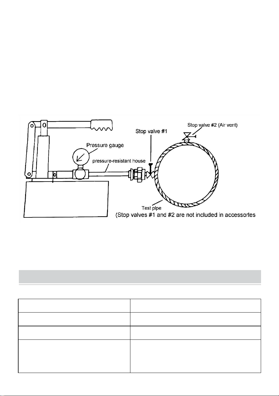
TESTING PROCEDURES
10. Installez les vannes d'arrêt sur le tuyau d'essai (#1,#2)
11. Remplissez le tube d'essai avec de l'eau en utilisant de l'eau de
service provenant d'une autre source d'approvisionnement.
12. Lorsque le tube de test est rempli d'eau, retirez l'air et fermez la
vanne (#2).
13. Connectez le testeur et le tube de test avec le test de maison
résistant à la pression ci-joint.
14. Remplissez le réservoir d'eau du testeur avec de l'eau et faites
- 5 -
fonctionner la pompe.
15. Ouvrez la vanne d'arrêt (#1) du tuyau d'essai et continuez
l'opération pour faire le plein d'eau.
16. Lorsque le manomètre équipé du testeur atteint la pression
requise, arrêtez de faire fonctionner la pompe.
17. Si la pression ne chute pas, le tube de test est parfait.
18. Si la pression chute, cela indique une fuite provoquée quelque
part sur le tuyau de test.
PERFORMANCE PARAMETER
Modèle
SYB-25
Capacité du réservoir
1,4 gallons
Plage de test de pression
0-25 bars
Spécification du tuyau
Tuyau résistant à la pression avec
connecteur fileté externe de ½
pouce

- 6 -
FAILURE RECOVERY
Lorsque la poignée
monte, l’eau ne
peut pas être
aspirée.
1. Vérifiez si le tuyau d'aspiration est bloqué par
des déchets.
2. Vérifiez si l'interrupteur est serré.
La poignée est
faible lors des
mouvements de
haut en bas.
1. Vérifiez si l'interrupteur est serré.
2. Vérifiez si la bague d'étanchéité de l'arbre du
piston est endommagée.
3. Vérifiez si le clapet anti-retour dans le joint de
sortie est sale.
Le manomètre
montre que la
pression est
instable.
1. S'il y a une fuite dans le pipeline ou le joint de
sortie, la bague d'étanchéité doit être remplacée.
2. La fuite de connexion de la tige du compteur,
remplacez le pays d'étanchéité.
3. Dommages au manomètre, réparer le
manomètre.
Attention particulière:
Ne pas utiliser sur des lieux de travail contenant des substances
acides, alcalines et corrosives .

- 7 -


- 2 -
Technisch Support- und E-Garantiezertifikat
www.vevor.com/support
Anweisungen zur Drucktestpumpe
MODELL: SYB-25
We continue to be committed to provide you tools with competitive price.
"Save Half", "Half Price" or any other similar expressions used by us only represents an
estimate of savings you might benefit from buying certain tools with us compared to the major
top brands and does not necessarily mean to cover all categories of tools offered by us. You
are kindly reminded to verify carefully when you are placing an order with us if you are
actually saving half in comparison with the top major brands.

- 1 -
MODELL: SYB-25
Have product questions? Need technical support? Please feel free to
contact us:
Technical Support and E-Warranty Certificate
www.vevor.com/support
NEED HELP? CONTACT US!
This is the original instruction, please read all manual instructions
carefully before operating. VEVOR reserves a clear interpretation of our
user manual. The appearance of the product shall be subject to the
product you received. Please forgive us that we won't inform you again if
there are any technology or software updates on our product.
Pressure Test Pump

- 2 -
Warnung: Um das Verletzungsrisiko zu verringern, muss der
Benutzer die Bedienungsanleitung sorgfältig lesen.
PRODUCT PRESENTATION
Die manuelle Druckprüfpumpe besteht aus Pumpenkörper, Kolben,
Dichtungsring, Steuerventil, Manometer, Wassertank usw.
Funktionsprinzip: Der Kolben wird am Griff angehoben, um im
Pumpenkörper ein Vakuum zu erzeugen, und das Einlassventil wird
geöffnet. Die Flüssigkeit gelangt durch das Filtersieb und die
Wasserleitung in den Pumpenkörper. Wenn der Griff Kraft zum
Herunterdrücken ausübt, wird das Einlassventil geschlossen, das
Auslassventil geöffnet, das Druckwasser wird ausgegeben und das
Wasser dringt in das erkannte Objekt ein. Die Arbeit wird in einem
solchen Zyklus durchgeführt, um die Druckprüfung des Nenndrucks
zu realisieren.
Besondere Aufmerksamkeit:
Nicht an Arbeitsplätzen mit sauren, alkalischen und ätzenden Stoffen
verwenden .
INSTALLATION STEPS
7. Richten Sie das Griffloch mit dem Pumpenkörperloch aus, stecken Sie
den Stift in das Griffloch, stecken Sie dann den Stift in das Stiftloch und
biegen Sie den Stift (Einzelheiten siehe Explosionsnummern 6 und 7).
8. Setzen Sie den Pumpenkörper auf den Tank, wobei der Griff zum
Wassertank zeigt. Richten Sie die Schraubenlöcher des Pumpenkörpers
mit denen des Wassertanks aus, setzen Sie die vier Schrauben in die
Schraubenlöcher ein und ziehen Sie sie mit einem Werkzeug fest.
( Einzelheiten siehe Explosionsnummern 8 und 9 ).

- 3 -
9. Installieren Sie das Saugrohr von der Innenseite des Wassertanks an
der Schnittstelle an der Unterseite des Pumpenkörpers (siehe
Explosionsdiagramm Nr. 4).
Setzen Sie den Dichtungsring in die Verbindung der Wasserleitung ein und
ziehen Sie dann die Verbindung der Wasserleitung und des
Pumpenkörpers fest (siehe Explosionszeichnung Nr. 10).
EXPLOSION DIAGRAM AND PARTS LIST
NEIN
.
BESCHREIBUNG
Me
ng
e
NEI
N.
BESCHREIBUNG
Men
ge
1
Drücken Sie den Griff mit
dem Messgerät
1
6
Stützstift
1
2
Wassertank
1
7
R-Snap
1
3
Schlauch mit Anschluss
1
8
Bolzen
4
4
Sieb
1
9
Schraubenmutter
4
5
O-Ring
2
10
Siegelring
2

- 4 -
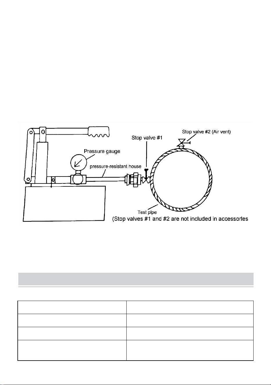
TESTING PROCEDURES
19. Installieren Sie die Absperrventile an der Testleitung (Nr. 1, Nr.
2).
20. Füllen Sie das Prüfrohr mit Wasser, indem Sie Brauchwasser
aus einer anderen Versorgungsquelle verwenden.
21. Wenn das Testrohr mit Wasser gefüllt ist, entfernen Sie die Luft
und schließen Sie das Ventil (Nr. 2).
22. Verbinden Sie das Prüfgerät und das Prüfrohr mit der
angeschlossenen druckfesten Hausprobe
- 5 -
23. Füllen Sie den Wassertank des Testers mit Wasser und
betreiben Sie die Pumpe.
24. Öffnen Sie das Absperrventil (Nr. 1) des Testrohrs und fahren
Sie mit dem Vorgang fort, um Wasser einzufüllen.
25. Wenn das am Tester angebrachte Manometer den
erforderlichen Druck erreicht, stoppen Sie den Betrieb der Pumpe.
26. Wenn der Druck nicht abfällt, ist das Testrohr perfekt.
27. Wenn der Druck abfällt, deutet dies auf eine Undichtigkeit
irgendwo im Prüfrohr hin.
PERFORMANCE PARAMETER
Modell
SYB-25
Tankinhalt _
1,4 Gallone
Druckprüfbereich _
0-25 bar
Schlauchspezifikation
Druckfester Schlauch mit ½ Zoll
Außengewindeanschluss

- 6 -
FAILURE RECOVERY
Wenn sich der Griff
nach oben bewegt,
kann das Wasser
nicht angesaugt
werden.
1. Prüfen Sie, ob das Saugrohr durch Schmutz
verstopft ist.
2. Überprüfen Sie, ob der Schalter festgezogen ist.
Der Griff ist beim
Auf- und
Abbewegen
schwach.
1. Prüfen Sie, ob der Schalter festgezogen ist.
2. Prüfen Sie, ob der Dichtring des Kolbenschafts
beschädigt ist.
3. Prüfen Sie, ob das Rückschlagventil im
Auslassstutzen verunreinigt ist.
Das Manometer
zeigt an, dass der
Druck instabil ist.
1. Bei Undichtigkeiten in der Rohrleitung oder
Auslassverbindung sollte der Dichtungsring
ausgetauscht werden.
2. Wenn die Messstabverbindung undicht ist,
ersetzen Sie das Dichtungsland.
3. Manometerschaden, Manometer reparieren.
Besondere Aufmerksamkeit:
Nicht an Arbeitsplätzen mit sauren, alkalischen und ätzenden Stoffen
verwenden .

- 7 -


- 2 -
Tecnico Supporto e certificato di garanzia elettronica
www.vevor.com/support
Istruzioni per la pompa di prova della pressione
MODELLO: SYB-25
We continue to be committed to provide you tools with competitive price.
"Save Half", "Half Price" or any other similar expressions used by us only represents an
estimate of savings you might benefit from buying certain tools with us compared to the major
top brands and does not necessarily mean to cover all categories of tools offered by us. You
are kindly reminded to verify carefully when you are placing an order with us if you are
actually saving half in comparison with the top major brands.

- 1 -
MODELLO: SYB-25
Have product questions? Need technical support? Please feel free to
contact us:
Technical Support and E-Warranty Certificate
www.vevor.com/support
NEED HELP? CONTACT US!
This is the original instruction, please read all manual instructions
carefully before operating. VEVOR reserves a clear interpretation of our
user manual. The appearance of the product shall be subject to the
product you received. Please forgive us that we won't inform you again if
there are any technology or software updates on our product.
Pressure Test Pump

- 2 -
Avvertenza: per ridurre il rischio di lesioni, l'utente deve leggere
attentamente il manuale di istruzioni.
PRODUCT PRESENTATION
La pompa per test di pressione manuale è composta da corpo
pompa, stantuffo, anello di tenuta, valvola di controllo, manometro,
serbatoio dell'acqua e così via.
Principio di funzionamento: lo stantuffo viene sollevato dalla maniglia
per creare un vuoto nel corpo della pompa e la valvola di ingresso
viene aperta. Il liquido entra nel corpo della pompa attraverso lo
schermo del filtro e il tubo dell'acqua. Quando la maniglia applica la
forza per premere verso il basso, la valvola di ingresso viene chiusa,
la valvola di uscita viene aperta, l'acqua sotto pressione viene
emessa e l'acqua entra nell'oggetto rilevato. Il lavoro viene eseguito
in tale ciclo per realizzare la prova di pressione della pressione
nominale.
Attenzione speciale:
Non utilizzare in ambienti di lavoro con sostanze acide, alcaline e
corrosive .
INSTALLATION STEPS
10. Allineare il foro della maniglia con il foro del corpo della pompa,
inserire il perno nel foro della maniglia, quindi inserire il perno nel foro del
perno e piegare il perno (vedere i numeri dell'esplosione 6 e 7 per i
dettagli).
11. Posizionare il corpo della pompa sul serbatoio, con la maniglia rivolta
verso il serbatoio dell'acqua. Allineare i fori delle viti del corpo della pompa
con quelli del serbatoio dell'acqua, posizionare i quattro bulloni nei fori

- 3 -
delle viti e serrarli con uno strumento. (vedi esplosione numeri 8 e 9 per i
dettagli).
12. Installare il tubo di aspirazione dall'interno del serbatoio dell'acqua
sull'interfaccia nella parte inferiore del corpo della pompa (vedere schema
di esplosione n. 4).
Mettere l'anello di tenuta nel giunto del tubo dell'acqua, quindi serrare il
giunto del tubo dell'acqua e il corpo della pompa (vedere diagramma di
esplosione n. 10).
EXPLOSION DIAGRAM AND PARTS LIST
NO.
DESCRIZIONE
Qt
à
NO
.
DESCRIZIONE
Qtà
1
Maniglia a pressione con
contatore
1
6
Perno di supporto
1
2
Serbatoio d'acqua
1
7
R-scatto
1
3
Tubo con connettore
1
8
Bullone
4
4
Filtro
1
9
Dado
4
5
O-ring
2
10
Anello di tenuta
2

- 4 -
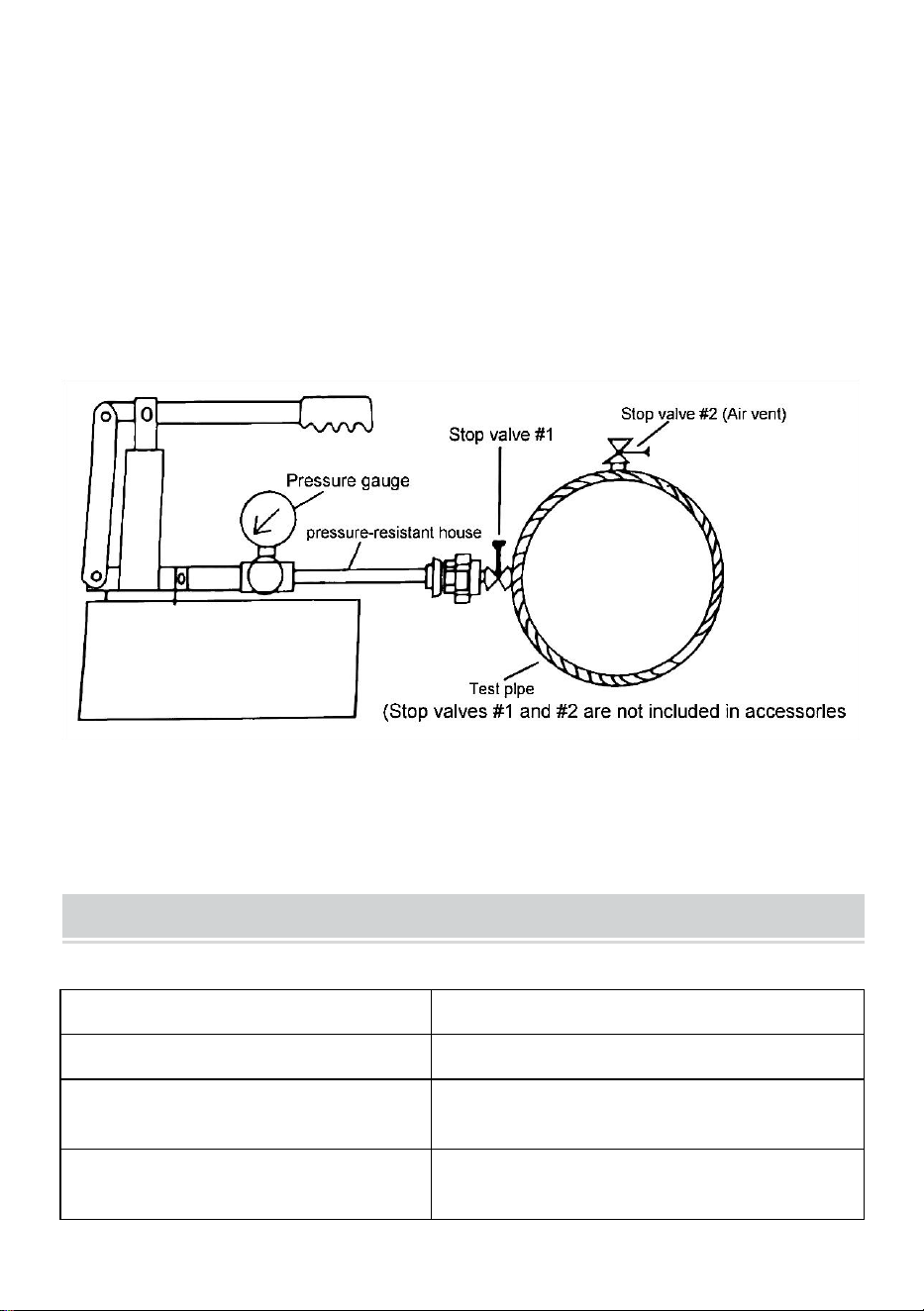
TESTING PROCEDURES
28. Installare le valvole di arresto sul tubo di prova (#1,#2)
29. Riempire il tubo di prova con acqua utilizzando acqua di servizio
di un'altra fonte di approvvigionamento.
30. Quando il tubo di prova è pieno d'acqua, rimuovere l'aria e
chiudere la valvola (n. 2).
31. Collegare il tester e il tubo di prova con il test domestico
resistente alla pressione allegato
32. Riempire il serbatoio dell'acqua del tester con acqua e azionare
- 5 -
la pompa.
33. Aprire la valvola di arresto (n. 1) del tubo di prova e continuare
l'operazione per riempire con acqua.
34. Quando il manometro in dotazione al tester raggiunge la
pressione richiesta, interrompere il funzionamento della pompa.
35. Se la pressione non scende, il tubo di prova è perfetto.
36. Se la pressione diminuisce, è indicativo di una perdita causata
da qualche parte sul tubo di prova.
PERFORMANCE PARAMETER
Modello
SYB-25
Capacità del serbatoio
1,4 galloni
Intervallo di prova della
pressione
0-25 bar
Specifiche del tubo
Tubo resistente alla pressione con
connettore filettato esterno da ½

- 6 -
pollice
FAILURE RECOVERY
Quando la maniglia
si sposta verso
l'alto, l'acqua non
può essere
aspirata.
1. Controllare se il tubo di aspirazione è ostruito da
rifiuti.
2. Controllare se l'interruttore è serrato.
La maniglia è
debole quando si
sposta su e giù.
1. Controllare se l'interruttore è serrato.
2. Controllare se l'anello di tenuta dell'albero del
pistone è danneggiato.
3. Controllare se la valvola di ritegno nel giunto di
uscita è sporca.
Il manometro indica
che la pressione è
instabile.
1. Se sono presenti perdite nella tubazione o nel
giunto di uscita, l'anello di tenuta deve essere
sostituito.
2. la perdita del collegamento dell'asta del
misuratore, sostituire il paese di tenuta.
3. Danno al manometro, riparare il manometro.
Attenzione speciale:
Non utilizzare in ambienti di lavoro con sostanze acide, alcaline e
corrosive .

- 7 -


- 2 -
Técnico Certificado de soporte y garantía electrónica
www.vevor.com/support
Instrucciones para la bomba de prueba de presión
MODELO: SYB-25
We continue to be committed to provide you tools with competitive price.
"Save Half", "Half Price" or any other similar expressions used by us only represents an
estimate of savings you might benefit from buying certain tools with us compared to the major
top brands and does not necessarily mean to cover all categories of tools offered by us. You
are kindly reminded to verify carefully when you are placing an order with us if you are
actually saving half in comparison with the top major brands.

- 1 -
MODELO: SYB-25
Have product questions? Need technical support? Please feel free to
contact us:
Technical Support and E-Warranty Certificate
www.vevor.com/support
NEED HELP? CONTACT US!
This is the original instruction, please read all manual instructions
carefully before operating. VEVOR reserves a clear interpretation of our
user manual. The appearance of the product shall be subject to the
product you received. Please forgive us that we won't inform you again if
there are any technology or software updates on our product.
Pressure Test Pump

- 2 -
Advertencia: para reducir el riesgo de lesiones, el usuario debe
leer atentamente el manual de instrucciones.
PRODUCT PRESENTATION
La bomba de prueba de presión manual se compone de un cuerpo
de bomba, un émbolo, un anillo de sellado, una válvula de control,
un manómetro, un tanque de agua, etc.
Principio de funcionamiento: el mango levanta el émbolo para crear
un vacío en el cuerpo de la bomba y se abre la válvula de entrada.
El líquido ingresa al cuerpo de la bomba a través de la rejilla del filtro
y la tubería de agua. Cuando el mango aplica fuerza para presionar
hacia abajo, la válvula de entrada se cierra, la válvula de salida se
abre, el agua a presión sale y el agua ingresa al objeto detectado. El
trabajo se lleva a cabo en dicho ciclo para realizar la prueba de
presión de la presión nominal.
Atención especial:
No utilizar en lugares de trabajo con sustancias ácidas, alcalinas y
corrosivas .
INSTALLATION STEPS
13. Alinee el orificio de la manija con el orificio del cuerpo de la bomba,
inserte el pasador en el orificio de la manija, luego inserte el pasador en el
orificio del pasador y doble el pasador (consulte las explosiones número 6
y 7 para obtener más detalles).
14. Coloque el cuerpo de la bomba en el tanque, con la manija hacia el
tanque de agua. Alinee los orificios para tornillos del cuerpo de la bomba
con los del tanque de agua, coloque los cuatro pernos en los orificios para
tornillos y apriételos con una herramienta. (ver explosiones números 8 y 9

- 3 -
para más detalles).
15. Instale la tubería de succión desde el interior del tanque de agua en la
interfaz en la parte inferior del cuerpo de la bomba (consulte el diagrama
de explosión No. 4).
Coloque el anillo de sellado en la unión de la tubería de agua y luego
apriete la unión de la tubería de agua y el cuerpo de la bomba (consulte el
diagrama de explosión No. 10).
EXPLOSION DIAGRAM AND PARTS LIST
No.
DESCRIPCIÓN
Ca
nti
da
d
No.
DESCRIPCIÓN
Cant
idad
1
Empuñadura de presión
con medidor.
1
6
Pasador de soporte
1
2
Depósito de agua
1
7
R-chasquido
1
3
Manguera con conector
1
8
Tornillo
4
4
Colador
1
9
Tuerca de tornillo
4
5
junta tórica
2
10
anillo de sellado
2
- 4 -
TESTING PROCEDURES
37. Instale las válvulas de cierre en el tubo de prueba (#1,#2)
38. Llene la tubería de prueba con agua utilizando agua de servicio
de otra fuente de suministro.
39. Cuando el tubo de prueba esté lleno de agua, retire el aire y
cierre la válvula (#2).
40. Conecte el probador y el tubo de prueba con el ensayo
doméstico resistente a la presión adjunto.
41. Llene el tanque de agua del probador con agua y opere la

- 5 -
bomba.
42. Abra la válvula de cierre (#1) del tubo de prueba y continúe la
operación para llenar con agua.
43. Cuando el manómetro equipado con el probador alcance la
presión requerida, deje de operar la bomba.
44. Si la presión no baja, el tubo de prueba está perfecto.
45. Si la presión cae, es indicativo de una fuga causada en algún
lugar del tubo de prueba.
PERFORMANCE PARAMETER
Modelo
SYB-25
Capacidad del tanque
1,4 galones
Rango de prueba de presión
0-25 barras
Especificación de la manguera
Manguera resistente a la presión con
conector roscado externo de ½
pulgada

- 6 -
FAILURE RECOVERY
Cuando el mango
se mueve hacia
arriba, no se puede
aspirar el agua.
1. Compruebe si el tubo de succión está bloqueado
por basura.
2. Compruebe si el interruptor está apretado.
El mango es débil
al moverlo hacia
arriba y hacia
abajo.
1. Compruebe si el interruptor está apretado.
2. Compruebe si el anillo de sellado del eje del
pistón está dañado.
3. Compruebe si la válvula de retención en la junta
de salida está sucia.
El manómetro
muestra que la
presión es
inestable.
1. Si hay fugas en la tubería o en la junta de salida,
se debe reemplazar el anillo de sellado.
2. Si hay fugas en la conexión de la varilla del
medidor, reemplace el país de sellado.
3. Daños en el manómetro, repare el manómetro.
Atención especial:
No utilizar en lugares de trabajo con sustancias ácidas, alcalinas y
corrosivas .

- 7 -


- 2 -
Techniczny Certyfikat wsparcia i e-gwarancji
www.vevor.com/support
Instrukcje dotyczące pompy do prób ciśnieniowych
MODEL: SYB-25
We continue to be committed to provide you tools with competitive price.
"Save Half", "Half Price" or any other similar expressions used by us only represents an
estimate of savings you might benefit from buying certain tools with us compared to the major
top brands and does not necessarily mean to cover all categories of tools offered by us. You
are kindly reminded to verify carefully when you are placing an order with us if you are
actually saving half in comparison with the top major brands.
- 1 -
MODEL: SYB-25
Have product questions? Need technical support? Please feel free to
contact us:
Technical Support and E-Warranty Certificate
www.vevor.com/support
NEED HELP? CONTACT US!
This is the original instruction, please read all manual instructions
carefully before operating. VEVOR reserves a clear interpretation of our
user manual. The appearance of the product shall be subject to the
product you received. Please forgive us that we won't inform you again if
there are any technology or software updates on our product.
Pressure Test Pump

- 2 -
Ostrzeżenie — aby zmniejszyć ryzyko obrażeń, użytkownik
musi uważnie przeczytać instrukcję obsługi.
PRODUCT PRESENTATION
Ręczna pompa do testowania ciśnienia składa się z korpusu pompy,
tłoka, pierścienia uszczelniającego, zaworu sterującego, manometru,
zbiornika wody i tak dalej.
Zasada działania: Tłok podnosi się za uchwyt, aby wytworzyć
podciśnienie w korpusie pompy, a zawór wlotowy zostaje otwarty.
Ciecz dostaje się do korpusu pompy przez sito filtra i rurę wodną.
Kiedy uchwyt przykłada siłę do dociśnięcia, zawór wlotowy zostaje
zamknięty, zawór wylotowy zostaje otwarty, woda pod ciśnieniem
wypływa i woda dostaje się do wykrytego obiektu. Praca
prowadzona jest w takim cyklu, aby zrealizować próbę ciśnieniową o
ciśnieniu znamionowym.
Specjalna uwaga:
Nie stosować w miejscach pracy z substancjami kwaśnymi,
zasadowymi i żrącymi .
INSTALLATION STEPS
16. Wyrównaj otwór uchwytu z otworem w korpusie pompy, włóż kołek do
otworu uchwytu, następnie włóż kołek do otworu na kołek i zagnij kołek
(szczegóły patrz numery eksplozji 6 i 7).
17. Umieść korpus pompy na zbiorniku uchwytem skierowanym w stronę
zbiornika na wodę. Wyrównaj otwory na śruby w korpusie pompy z
otworami w zbiorniku na wodę, umieść cztery śruby w otworach na śruby i
dokręć je za pomocą narzędzia. ( szczegóły patrz numery eksplozji 8 i 9 ).
18. Zamontować rurę ssącą od wnętrza zbiornika wody na interfejsie w

- 3 -
dolnej części korpusu pompy (patrz schemat wybuchu nr 4).
Włóż pierścień uszczelniający w złącze rury wodnej, a następnie dokręć
połączenie rury wodnej z korpusem pompy (patrz schemat wybuchu nr 10).
EXPLOSION DIAGRAM AND PARTS LIST
NIE.
OPIS
Iloś
ć
NIE
.
OPIS
Ilość
1
Uchwyt dociskowy z
miernikiem
1
6
Kołek podporowy
1
2
Zbiornik wodny
1
7
R-trzask
1
3
Wąż ze złączem
1
8
Śruba
4
4
Filtr
1
9
Nakrętka
4
5
O-ring
2
10
Uszczelka
2

- 4 -
TESTING PROCEDURES
46. Zamontuj zawory odcinające na rurze testowej (#1, #2)
47. Napełnij rurę testową wodą, używając wody użytkowej z innego
źródła.
48. Gdy rura testowa napełni się wodą, usuń powietrze i zamknij
zawór (nr 2).
49. Podłącz tester i rurkę testową z dołączonym, odpornym na
ciśnienie testem domowym
50. Napełnij zbiornik testera wodą i uruchom pompę.

- 5 -
51. Otwórz zawór odcinający (nr 1) rury testowej i kontynuuj
operację, aby uzupełnić wodę.
52. Gdy manometr wyposażony w tester wzrośnie do wymaganego
ciśnienia, należy przerwać pracę pompy.
53. Jeśli ciśnienie nie spada, rura testowa jest idealna.
54. Jeśli ciśnienie spadnie, oznacza to wyciek spowodowany gdzieś
na rurze testowej.
PERFORMANCE PARAMETER
Model
SYB-25
Pojemność baku
1,4 galona
Zakres testu ciśnienia
0-25 barów
Specyfikacja węża
Wąż odporny na ciśnienie z
przyłączem z gwintem zewnętrznym
½ cala

- 6 -
FAILURE RECOVERY
Kiedy uchwyt
przesuwa się do
góry, woda nie
może zostać
zassana.
1. Sprawdź, czy rura ssąca nie jest zatkana
śmieciami.
2. Sprawdź, czy przełącznik jest dokręcony.
Uchwyt jest słaby
podczas
poruszania się w
górę i w dół.
1. Sprawdź, czy przełącznik jest dokręcony.
2. Sprawdź, czy pierścień uszczelniający wału tłoka
nie jest uszkodzony.
3. Sprawdź, czy zawór zwrotny na złączu
wylotowym nie jest zanieczyszczony.
Manometr
pokazuje, że
ciśnienie jest
niestabilne.
1. W przypadku nieszczelności rurociągu lub
złącza wylotowego należy wymienić pierścień
uszczelniający.
2. Nieszczelność połączenia pręta licznika,
wymienić krajkę uszczelniającą.
3. uszkodzenie manometru, naprawić manometr.
Specjalna uwaga:
Nie stosować w miejscach pracy z substancjami kwaśnymi,
zasadowymi i żrącymi .

- 7 -


- 2 -
Technisch Ondersteuning en e-garantiecertificaat
www.vevor.com/support
Instructies voor druktestpomp
MODEL: SYB-25
We continue to be committed to provide you tools with competitive price.
"Save Half", "Half Price" or any other similar expressions used by us only represents an
estimate of savings you might benefit from buying certain tools with us compared to the major
top brands and does not necessarily mean to cover all categories of tools offered by us. You
are kindly reminded to verify carefully when you are placing an order with us if you are
actually saving half in comparison with the top major brands.

- 1 -
MODEL: SYB-25
Have product questions? Need technical support? Please feel free to
contact us:
Technical Support and E-Warranty Certificate
www.vevor.com/support
NEED HELP? CONTACT US!
This is the original instruction, please read all manual instructions
carefully before operating. VEVOR reserves a clear interpretation of our
user manual. The appearance of the product shall be subject to the
product you received. Please forgive us that we won't inform you again if
there are any technology or software updates on our product.
Pressure Test Pump

- 2 -
Waarschuwing-Om het risico op letsel te verminderen, moet de
gebruiker de handleiding zorgvuldig lezen.
PRODUCT PRESENTATION
Handmatige druktestpomp bestaat uit een pomplichaam, plunjer,
afdichtring, regelklep, manometer, watertank enzovoort.
Werkingsprincipe: De plunjer wordt aan de hendel opgetild om een
vacuüm in het pomplichaam te creëren en de inlaatklep wordt
geopend. De vloeistof komt het pomplichaam binnen via het
filterscherm en de waterleiding. Wanneer de hendel kracht uitoefent
om naar beneden te drukken, wordt de inlaatklep gesloten, de
uitlaatklep geopend, wordt er water onder druk afgegeven en komt
het water het gedetecteerde object binnen. In een dergelijke cyclus
worden de werkzaamheden uitgevoerd om de druktest van de
nominale druk te realiseren.
Speciale aandacht:
Niet gebruiken op werkplekken met zure, alkalische en bijtende
stoffen .
INSTALLATION STEPS
19. Lijn het handvatgat uit met het gat in het pomplichaam, steek de pin in
het handvatgat, steek vervolgens de pin in het pingat en buig de pin (zie
explosienummers 6 en 7 voor details).
20. Plaats het pomplichaam op de tank, met de hendel naar de watertank
gericht. Lijn de schroefgaten van het pomphuis uit met die van de
watertank, plaats de vier bouten in de schroefgaten en draai ze vast met
gereedschap. (zie explosienummers 8 en 9 voor details).
21. Installeer de aanzuigleiding vanaf de binnenkant van de watertank op

- 3 -
de interface aan de onderkant van het pomphuis (zie explosiediagram nr.
4).
Plaats de afdichtring in de verbinding van de waterleiding en draai
vervolgens de verbinding van de waterleiding en het pomplichaam vast
(zie explosiediagram nr. 10).
EXPLOSION DIAGRAM AND PARTS LIST
Nee.
BESCHRIJVING
Aa
nta
l
Ne
e.
BESCHRIJVING
Aant
al
1
Druk op handgreep met
meter
1
6
Steunpin
1
2
Watertank
1
7
R-snap
1
3
Slang met aansluiting
1
8
Bout
4
4
Zeef
1
9
Schroef Bout
4
5
O-ring
2
10
Afsluitring
2

- 4 -
TESTING PROCEDURES
55. Installeer de afsluiters op de testleiding (#1, #2)
56. Vul de testleiding met water door gebruik te maken van
leidingwater van een andere toevoerbron.
57. Wanneer de testleiding gevuld is met water, verwijdert u de lucht
en sluit u de klep (#2).
58. Verbind de tester en de testleiding met de bijgevoegde
drukbestendige huistest
59. Vul de watertank van de tester met water en bedien de pomp.
- 5 -
60. Open de afsluiter (#1) van de testleiding en ga door met het
vullen met water.
61. Wanneer de manometer waarmee de tester is uitgerust, de
vereiste druk heeft bereikt, stop dan met het bedienen van de pomp.
62. Als de druk niet daalt, is de testleiding perfect.
63. Als de druk daalt, duidt dit op lekkage ergens in de testleiding.
PERFORMANCE PARAMETER
Model
SYB-25
Tankinhoud _
1,4 gallon
Druktestbereik _
0-25bar
Slangspecificatie
Drukbestendige slang met ½ inch
externe schroefdraadaansluiting

- 6 -
FAILURE RECOVERY
Wanneer de hendel
naar boven
beweegt, kan het
water niet worden
opgezogen.
1. Controleer of de zuigleiding verstopt is door
afval.
2. Controleer of de schakelaar goed vastzit.
Het handvat is
zwak bij het op en
neer bewegen.
1. Controleer of de schakelaar goed vastzit.
2. Controleer of de afdichtring van de zuigeras
beschadigd is.
3. Controleer of de terugslagklep in de
uitlaatverbinding vuil is.
De manometer
geeft aan dat de
druk instabiel is.
1. Als er lekkage is in de pijpleiding of
uitlaatverbinding, moet de afdichtring worden
vervangen.
2. De lekkage van de meterstangaansluiting,
vervang het afdichtingsland.
3. Schade aan de manometer, repareer de
manometer.
Speciale aandacht:
Niet gebruiken op werkplekken met zure, alkalische en bijtende
stoffen .

- 7 -


- 2 -
Teknisk Support och e-garanticertifikat
www.vevor.com/support
Instruktioner för trycktestpump
MODELL: SYB-25
We continue to be committed to provide you tools with competitive price.
"Save Half", "Half Price" or any other similar expressions used by us only represents an
estimate of savings you might benefit from buying certain tools with us compared to the major
top brands and does not necessarily mean to cover all categories of tools offered by us. You
are kindly reminded to verify carefully when you are placing an order with us if you are
actually saving half in comparison with the top major brands.

- 1 -
MODELL: SYB-25
Have product questions? Need technical support? Please feel free to
contact us:
Technical Support and E-Warranty Certificate
www.vevor.com/support
NEED HELP? CONTACT US!
This is the original instruction, please read all manual instructions
carefully before operating. VEVOR reserves a clear interpretation of our
user manual. The appearance of the product shall be subject to the
product you received. Please forgive us that we won't inform you again if
there are any technology or software updates on our product.
Pressure Test Pump

- 2 -
Varning - För att minska risken för skada måste användaren
läsa instruktionerna noggrant.
PRODUCT PRESENTATION
Manuell trycktestpump består av pumpkropp, kolv, tätningsring,
kontrollventil, tryckmätare, vattentank och så vidare.
Arbetsprincip: Kolven lyfts upp av handtaget för att skapa ett vakuum
i pumpkroppen och inloppsventilen öppnas. Vätskan kommer in i
pumpkroppen genom filtersilen och vattenröret. När handtaget
trycker ned kraft stängs inloppsventilen, utloppsventilen öppnas,
tryckvattnet matas ut och vattnet kommer in i det detekterade
föremålet. Arbetet utförs i en sådan cykel för att realisera trycktestet
av det nominella trycket.
Särskild uppmärksamhet:
Använd inte på arbetsplatser med syra, alkali och frätande ämnen .
INSTALLATION STEPS
22. Rikta in handtagshålet med pumphusets hål, för in stiftet i
handtagshålet, för sedan in stiftet i stifthålet och böj stiftet ( se
explosionsnummer 6 och 7 för detaljer).
23. Placera pumphuset på tanken, med handtaget mot vattentanken. Rikta
in skruvhålen på pumphuset med hålen i vattentanken, placera de fyra
bultarna i skruvhålen och dra åt dem med ett verktyg. (se
explosionsnummer 8 och 9 för detaljer).
24. Installera sugröret från insidan av vattentanken på gränssnittet i botten
av pumphuset (se explosionsdiagram nr 4).
Sätt tätningsringen i skarven på vattenröret och dra sedan åt skarven
mellan vattenröret och pumphuset (se explosionsdiagram nr 10).

- 3 -
EXPLOSION DIAGRAM AND PARTS LIST
Nej.
BESKRIVNING
Ant
al
Nej
.
BESKRIVNING
Anta
l
1
Tryckhandtag med
mätare
1
6
Stödstift
1
2
Vattentank
1
7
R-snäpp
1
3
Slang med anslutning
1
8
Bult
4
4
Sil
1
9
Mutter
4
5
O-ring
2
10
Tätningsring
2

- 4 -
TESTING PROCEDURES
64. Installera stoppventilerna på teströret (#1,#2)
65. Fyll provröret med vatten genom att använda servicevatten från
annan tillförselkälla.
66. När teströret är fyllt med vatten, ta bort luft och stäng ventilen
(#2).
67. Anslut testaren och teströret med den bifogade tryckbeständiga
husanalysen
68. Fyll vattentanken på testaren med vatten och kör pumpen.
- 5 -
69. Öppna stoppventilen (#1) på teströret och fortsätt operationen
för att fylla på med vatten.
70. När tryckmätaren som är utrustad med testaren stiger till det
önskade trycket, sluta använda pumpen.
71. Om trycket inte sjunker är teströret perfekt.
72. Om trycket sjunker är det ett tecken på läckage orsakat
någonstans på provröret.
PERFORMANCE PARAMETER
Modell
SYB-25
Tank kapacitet
1,4 gallon
Trycktestområde _
0-25 bar
Slangspecifikation
Trycktålig slang med ½ tum extern
gängad anslutning

- 6 -
FAILURE RECOVERY
När handtaget rör
sig uppåt kan
vattnet inte sugas
upp.
1. Kontrollera om sugröret är blockerat av skräp.
2. Kontrollera om strömbrytaren är åtdragen.
Handtaget är svagt
när man rör sig upp
och ner.
1. Kontrollera om brytaren är åtdragen.
2. Kontrollera om tätningsringen på kolvaxeln är
skadad.
3. Kontrollera om backventilen i utloppsleden är
oren.
Tryckmätaren visar
att trycket är
instabilt.
1. Om det finns läckage i rörledningen eller
utloppsskarven ska tätningsringen bytas ut.
2. Mätarstångens anslutningsläckage, byt ut
tätningslandet.
3. skador på tryckmätaren, reparera tryckmätare.
Särskild uppmärksamhet:
Använd inte på arbetsplatser med syra, alkali och frätande ämnen .

- 7 -