
SPECIFY CATALOG NO. AND SERIAL NO. WHEN ORDERING PARTS
COIL ROOFING NAILER
CATALOG NO. 7220-21
MILWAUKEE ELECTRIC TOOL CORPORATION
13135 W. Lisbon Road, Brookfi eld, WI 53005
Drwg. 1
54-43-0035
SERVICE PARTS LIST
BULLETIN NO.
0
00
EXAMPLE:
Component Parts
(Small #) Are Included
When Ordering The
Assembly (Large #).
FIG. PART NO. DESCRIPTION OF PART NO. REQ.
G99A
REVISED BULLETIN
DATE
Oct. 2015
WIRING INSTRUCTION
STARTING
SERIAL NUMBER
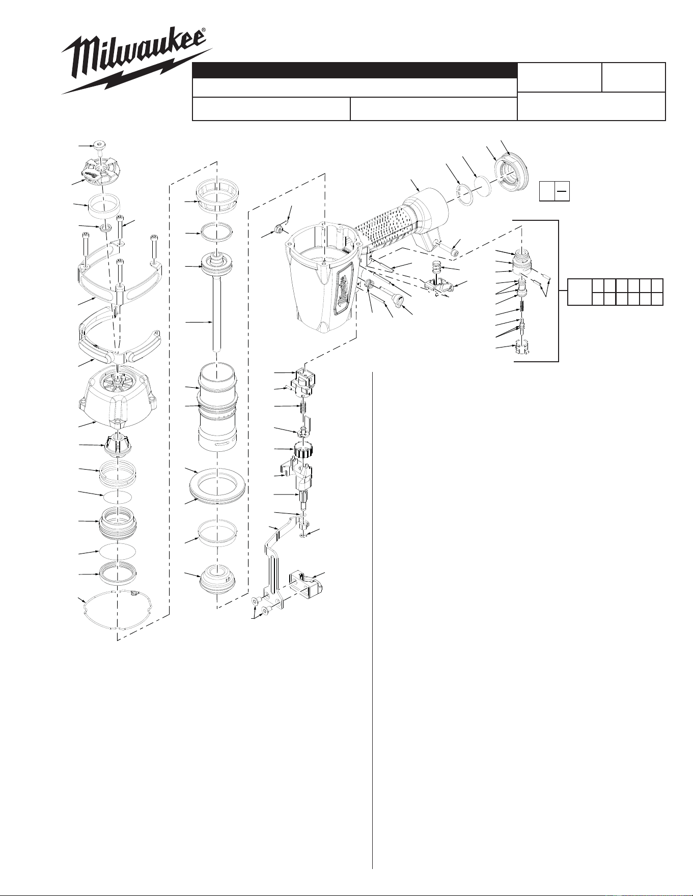
1 05-84-0805 Defl ector Bolt 1
2 31-05-0400 Defl ector 1
3 43-31-0355 Muffl er 1
4 45-88-1720 Defl ector Pad 1
5 05-84-0925 Socket Hex Head Screw 5
6 44-66-1355 Wear Plate 1
7 42-38-0370 Wear Pad 1
8 42-92-1425 Top Cap 1
9 45-06-0945 Seal 1
10 40-50-3120 Upper Valve Spring 1
11 34-40-3195 O-Ring 1
12 44-62-0265 Head Valve Piston 1
13 34-40-3245 O-Ring 1
14 42-76-0815 Valve Collar 1
15 45-06-0915 Seal 1
16 44-90-0700 Press Ring 1
17 44-90-0730 Piston Ring 1
18 34-40-3180 O-Ring 1
19 43-12-0255 Driver Assembly 1
20 42-98-0355 Cylinder 1
21 34-40-3135 O-Ring 1
22 45-36-1655 Cylinder Spacer 1
23 34-40-3200 O-Ring 1
24 44-90-0805 Cylinder Ring 1
25 42-38-0315 Bumper 1
26 34-40-3295 O-Ring 1
27 34-40-3300 O-Ring 1
28 42-52-0410 Plunger Cap 1
29 44-70-0250 Valve Plunger 1
30 34-40-3285 O-Ring 2
31 34-40-3280 O-Ring 1
32 40-50-3195 Spring 1
33 44-70-0255 Trigger Valve Plunger 1
34 34-40-3290 O-Ring 2
35 43-64-0150 Trigger Valve Head 1
36 06-65-1465 Spring Pin 2
37 06-65-1440 Spring Pin 2
38 06-65-1425 Spring Pin 1
39 31-92-0200 Trigger Assembly 1
40 40-50-3160 Spring 1
41 44-86-0710 Retainer 1
42 44-10-0650 Selector 1
43 40-50-3095 Selector Spring 1
44 44-90-0825 Ring 1
45 28-50-0805 Tool Body 1
46 44-90-0750 Retaining Ring 1
47 43-31-0370 Filter 1
48 42-92-1355 End Cap 1
49 34-40-3250 O-Ring 1
82 43-56-0865 Work Contact Element Guide 1
83 06-65-1405 Spring Pin 1
84 40-50-3050 Adjustment Spring 1
85 42-36-1970 Contact Bracket B 1
86 43-98-0755 Depth Adjustment Knob 1
87 42-92-1500 Work Contact Element Cover 1
88 44-94-0580 Adjustment Rod Assembly 1
89 34-40-3170 O-Ring 1
90 42-36-1985 Contact Element Bracket 1
91 44-90-0770 E-Ring 1
92 42-36-1960 Contact Element Bracket A 1
93 05-85-0050 Flat Head Hex Bolt 2
57 40-50-3005 Feed Finger Spring 1
58 44-86-0705 Retainer Ring 1
59 34-40-3235 O-Ring 1
60 34-40-3205 O-Ring 1
61 40-50-3085 Feed Piston Spring 1
62 42-38-0345 Feed Bumper 1
106 05-84-0845 Bolt Assembly 1
111 31-94-0110 Trigger Valve Assembly 1
111
26 27 28 29 30 31
32 33 34 35 36 44
FIG. PART NO. DESCRIPTION OF PART NO. REQ.
1
2
3
4
5
6
7
8
9
10
11
12
13
14
15
16
17
18
19
20
21
22
23
24
25
93
92
91
90
82
83
84
85
86
87
88
89
26
27
28
29
30
31
32
33
34
35
36
43
37
42
37
39
40
38
106
44
41
45
46
47
48
49
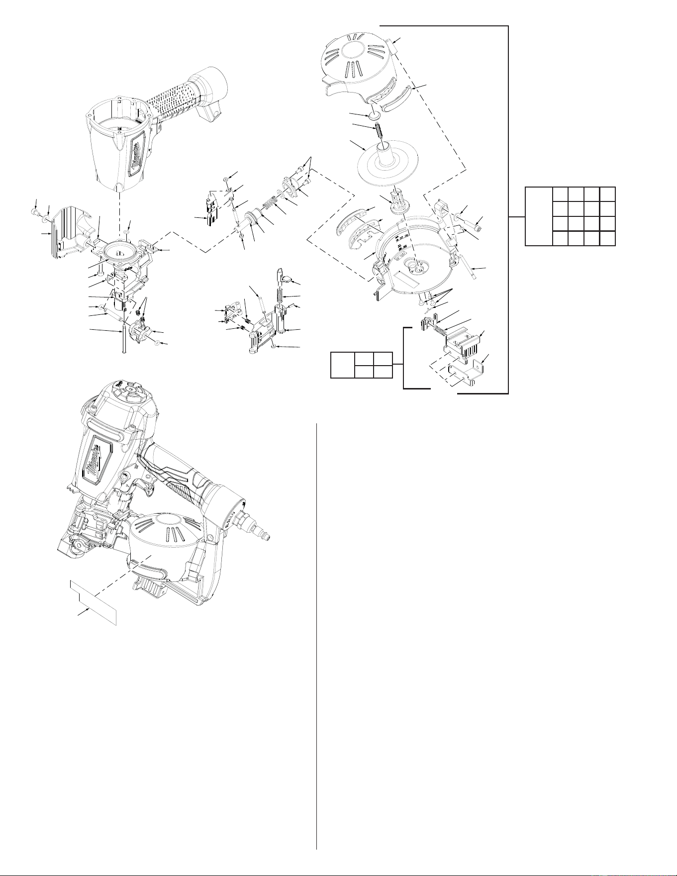
50 30-61-0200 Nose Piece 1
51 34-40-3165 O-Ring 1
52 34-40-3265 O-Ring 2
53 44-55-0250 Feed Finger 1
54 05-84-0915 Bolt Assembly 4
55 44-62-0260 Feed Piston 1
56 44-60-1905 Feed Piston Pin 1
57 40-50-3005 Feed Finger Spring 1
58 44-86-0705 Retaining Ring 4
59 34-40-3235 O-Ring 1
60 34-40-3205 O-Ring 1
61 40-50-3085 Feed Piston Spring 1
62 42-38-0345 Feed Bumper 1
63 42-92-1415 Feed Piston Cap 1
64 05-84-0820 Bolt Assembly 2
65 44-55-0260 First Stopper Finger 1
66 44-55-0255 Second Stopper Finger 1
67 40-50-3010 Spring 1
68 40-50-3080 Stopper Finger Spring 3
69 44-60-1895 Nail Stop Pin 1
70 42-92-1410 Door 1
71 40-50-3015 Latch Spring 1
72 44-20-0860 Door Latch 1
73 06-65-1415 Spring Pin 1
74 44-50-0205 Door Shaft Pin 1
75 43-56-0890 Guide Block 1
76 44-60-1860 Fixed Pin 1
77 34-40-3190 O-Ring 2
78 42-92-1480 Work Contact Element Cover 1
79 45-88-1760 Flat Washer 2
80 05-84-0895 Bolt, M5 x 0.8-08 1
81 44-26-0100 Magnet 1
94 44-60-1885 Pin 2
95 42-38-0355 Magazine Cover 1
96 43-78-0165 Spring Base A 1
97 40-50-3040 Pull Spring 1
98 45-36-1660 Spacer 1
99 44-55-0265 Nail Tray Adjustor 1
100 05-78-0815 Tap Bolt 3
101 42-98-0375 Magazine Base 1
102 34-40-3130 O-Ring 1
103 44-86-0715 Spring Retainer 1
104 42-38-0365 Magazine Wear Pad B 2
105 42-98-0380 Magazine Wear Pad A 1
106 05-84-0845 Bolt Assembly 1
107 44-66-1335 Positional Plate 1
108 40-50-3055 Work Contact Element Spring 1
109 44-66-1330 Adjusting Plate A 1
110 44-66-1325 Adjusting Plate B 1
112 45-24-0020 Magazine Coil Assembly 1
113 43-56-0565 Shingle Guide Assembly 1
115 12-98-0310 Service Nameplate/Warning Label 1
14-70-0140 Overhaul Kit (Not Shown) 1
14-70-0160 Driver Maintenance Kit (Not Shown) 1
112
94 95 96 97
98 99 100 101
102 103 104 105
107 108 109 110
FIG. PART NO. DESCRIPTION OF PART NO. REQ.
FIG. PART NO. DESCRIPTION OF PART NO. REQ.
115
52
54
58
50
77
76
74
80
79
78
69
68
65
66
67
72
71
73
70
58
68
75
77
100
103
107
108
109
110
102
106
79
94
81
51
50
58
59
60
55
61
62
63
101
105
104
99
53
58
57
56
64
96
97
98
95
104
113
107 108
109 110

Disassembly:
1, 2, 3, 4, 8 Remove bolt (1) from top cap (8) using a 4 mm hex key and remove assembly (2, 3, 4)
5, 8 Remove four screws (5) from top cap (8) using a 4 mm hex key.
8, 9, 10, 11, 12,
13, 14
Using a 1/8 in. punch, gently push valve assembly (9, 10, 11, 12, 13, and 14) out of top cap (8) through the holes in the cover.
16, 17, 18, 19, 20,
21, 22, 23, 24,
25, 45
Remove press ring (16) from top of cylinder (20), turn tool body (45) over and tap outside edge of tool body against a piece of
wood to separate assembly (17-25) from tool body.
20, 22, 23, 24 Remove cylinder ring (24) from cylinder (20) prior to removing cylinder spacer assembly (22, 23).
45,50,79, 106,112 Remove screw (106) and washer (79) from tool body (45) to lift magazine coil assembly (112) off nose piece (50).
37, 38, 39, 40, 41,
42, 43, 44, 45, 111
Remove trigger valve assembly (111) from tool body (45) by placing a 3/32 in. (2.5mm) punch inside half-moon slot of retainer
(41) and gently tapping shaft of selector (42). Remove spring (43), retainer (41), and ring (44). Remove trigger and spring
(39,40) from tool body and push pins (37, 38) out of tool body (45) just far enough to remove valve assembly. Note: Once pins
(37, 38) have been moved, trigger valve assembly (111) can be gently pushed out of the tool body from the inside handle area
of the tool body using a fl at blade screwdriver.
Note: Use service fi xture #61-60-0005 to move spring pins (42, 43), or use a 1/8" punch.
Reassembly:
50, 63, 64 Apply Blue Loctite
®
, 242, onto threads of screws (64) prior to installing feed piston cap (63) onto nose assembly (50).
50, 78, 80 Apply Blue Loctite
®
onto threads of screw (80) prior to installing work contact element cover (78) onto nose assembly (50).
90, 92, 93 Apply Red Loctite
®
onto threads of screws (93) when securing contact element bracket (90) to contact element bracket A (92).
37, 38, 45, 111 Reinstall trigger valve assembly (111) into tool body (45) by aligning the grooves in the valve assembly with the two holes for
spring pins (37, 38). Drive spring pins into tool body until they are fl ush with the casting surface.
Use service fi xture #61-60-0005 to reinstall pins (37, 38).
39, 40, 41, 42, 43,
44, 45
Reinstall selection lever assembly (41, 42, 43, 44,) and trigger assembly (39, 40) by doing the following.
• Place spring (43) onto shaft of selection lever (42)
• Position spring (40) and trigger (39) over plunger of trigger valve assembly (111)
• Insert selection lever assembly (42, 43) into tool body (45) and align half-moon slot of retainer (41) with half-moon
shaft of selection lever (42) and snap retainer assembly (41, 44) onto the shaft
20, 21, 22, 23 Install o-ring (21) onto cylinder (20) prior to installing cylinder spacer assembly (22, 23).
20, 22, 23, 24 Install cylinder ring (24) onto cylinder (20) only after cylinder ring assembly (22, 23) have been installed.
Note: Large fl anged end of cylinder ring (24) must facing the top of cylinder (20) when installed.
17, 18, 19, 20, 21,
22, 23, 24, 25,
45, 50
Install preassembled driver assembly (17, 18, and 19) into preassembled cylinder assembly (20, 21, 22, 23, 24, and 25) and
install assembled components into tool body (45). Note: Orientation of driver assembly (19) must match orientation in nose
assembly (50).
8, 16, 20 Install press ring (16) onto top of cylinder (20) with wide edge facing toward top cap (8).
2, 6, 7 Install bumper band pad (7) into bumper band (6) with the word ‘TOP’ facing toward defl ector (2).
47, 48 Install smooth side of fi lter (47) toward end cap (48).
1, 8 Apply Blue Loctite
®
onto threads of screw (1) if removed from top cap (8).

Lubrication:
Type I Grease 49-08-7100
Clean all parts with a dry clean cloth.
8, 9, 10, 11, 12,
13, 14,
Place a thin coating of grease into internal bore of top cap (8), coat parts (9-14) and reassemble in order shown.
18, 17, 19 Coat o-ring (18) and piston ring (17) prior to installing into groove of driver assembly (19).
20, 21, 22, 23, 24 Coat cylinder o-ring (21), cylinder spacer (22), o-ring (23) and cylinder ring (24) prior to installing onto cylinder (20).
26, 27 28, 29, 30,
31, 32, 33, 34,
35, 36
Coat all parts of the trigger valve assembly if being replaced individually. Components cleaned in any type of solvent or
water solution will require new lubrication. Note: A new trigger valve assembly will be pre-lubricated and will not require any
additional lubrication.
50, 55, 56, 57, 59,
60, 61, 62
Place a thin coating of grease into pocket of feed piston located on nose (50). Once pocket area has been coated, coat
additional components (55, 56, 57, 59, 60, 61, and 62).