Page 1 of 69
MH64834
Infinite Series
OWNERS MANUAL
2023
April 21, 2021
Page 2 of 69
DANGER: IF YOU SMELL GAS
1. Shut off gas to the appliance.
2. Extinguish any open flame.
3. Open lid and doors and remove any storage cover(s).
4. If the odor continues, keep away from the appliance and immediately call your gas
supplier or fire department.
Failure to follow these instructions could result in fire or explosion which could cause property
damage, personal injury or death.
WARNING: FOR YOUR SAFETY
DO NOT store or use gasoline or other flammable vapors and liquids in the vicinity of this or any
other appliance.
DO NOT check for leaks with a match or open flame.
DO NOT store an LP cylinder that is not connected for use in the vicinity of this or any other
appliance.
DO NOT
use your unit if there is evidence of damage (cuts, cracks, burns) or excessive wear to the
gas supply hose.
DO NOT obstruct the flow of combustion and ventilation air to the unit.
DO NOT
place combustibles on the undershelf. Do not stand on the undershelf as it could result in
injury or irreparable damage.
DO NOT leave your unit unattended while in operation.
DO NOT use under the influence of alcohol or drugs.
DO NOT use this unit until you have read and understood all of the information in this manual.
WARNING: Instructions to be followed in the event that a user smells gas must be
posted in a prominent location. This information shall be obtained by consulting
the local gas supplier.
Page 3 of 69
Congratulations and thank you for choosing Crown
Verity.
The Infinite Series Product line was developed for
high performance and flexibility of design making it
distinctly different than any other grill line.
This manual contains important information
necessary for the proper and safe use of the
product. Please read this manual carefully and
follow all warnings and instructions to ensure safe
operation and to maximize your cooking
enjoyment.
Crown Verity is here to help. Should you ever have
any questions about cooking with or caring for your
Crown Verity product, please contact our customer
service desk at:
1-888-505-7240 or service@crownverity.com
Please have your model number and serial number
ready when you call or include it in your email.
Model Number
Serial Number
Note: The serial number and model number can be found on the rating plate (See Appendix A
for rating plate references).
THIS MANUAL MUST REMAIN WITH THE PRODUCT
OWNER FOR FUTURE REFERENCE.
PROUDLY MADE IN
NORTH AMERICA

Page 4 of 69
Understanding Compliance Ratings
There are several standards that apply to Outdoor Cooking Appliances. These standards can be
divided into two categories for either residential or commercial applications. It is important to
note that these differences in compliance have been put in place to ensure that the outdoor
cooking appliance will work properly and safely in the environment for which it is used.
Commercial appliances in general will be used more frequently than a residential appliance as
they are typically purchased for commercial applications such as restaurants, resorts, golf
courses, etc. As a result, the commercial standards ensure that frequent use of the product and
durability is considered. Commercial products also tend to be used by professional Chefs, so
the residential standards provide additional safety features to ensure safe operation in
residential applications.
Crown Verity recognizes the commercial and residential distinctions but does not want to
compromise commercial performance for residential compliance. As a result, the Infinite series
has been designed to meet both the residential and commercial standards for outdoor cooking
appliances. This ensures both performance and safety for all of our customers.
The Infinite Series of products were tested at Underwriters Laboratories (UL) and meet or
exceed the following standards:
RESIDENTIAL STANDARDS
ANSI Z21.58 2018 Outdoor Cooking Gas Appliances
CSA 1.6 2018 Outdoor Cooking Gas Appliances
COMMERCIAL STANDARDS
ANSI Z83.11 2016 Gas Food Service Equipment
CSA 1.8 2016 Gas Food Service Equipment
These standards will be noted on the rating plates of the appliances (See “Appendix A” for
rating plate references).

Page 5 of 69
For your Safety
WARNING: This appliance shall be used only in a well-ventilated space and shall not be used in
a building, garage, or any other enclosed area. Ensure that the clearances to combustibles are
adhered to as listed in this manual.
WARNING: Improper installation, adjustment, alteration, service or maintenance can cause
property damage, injury or death. Please read the operating and maintenance instructions
provided in this manual thoroughly before installing or servicing this equipment. It is your
responsibility to see that your units are properly assembled, installed, and cared for.
WARNING: Keep any electrical supply cords and fuel supply hose(s) away from any hot
surfaces.
WARNING: This appliance has been tested according to ANSI Z83.11/CSA 1.8 for commercial
applications and ANSI Z21.58/CSA 1.6 for residential use. This is an outdoor cooking appliance
and is not intended to be installed in or on a boat or recreational vehicle.
California Proposition 65 Warning
The burning of gas cooking fuel generates some by-products that are on the list of substances
which are known by the State of California to cause cancer or reproductive harm. California law
requires businesses to warn customers of potential exposure to such substances. To minimize
exposure to these substances, always operate the unit according to this Owner’s Manual, and
ensure you provide proper ventilation when cooking with gas.
IMPORTANT: Damage caused by a failure to heed the warnings or follow the safety
instructions and practices described in this manual is not covered by the warranty.

Page 6 of 69
Inspecting Your Shipped Appliances
IF SHIPMENT ARRIVES DAMAGED
This product was carefully inspected and tested before leaving the factory. Upon acceptance of
the shipment, all freight damage responsibility is relinquished by the freight carrier.
VISIBLE LOSS OR DAMAGE
• Be sure any visible damage to the carton is noted on the freight bill or express receipt and
signed by the person making the delivery.
• FILE CLAIM OR DAMAGES IMMEDIATELY, regardless of extent of damage
CONCEALED LOSS OR DAMAGE
• If damaged is unnoticed until the appliance is unpacked, notify the transportation company
or carrier immediately and file a “concealed damage” claim with them. This should be done
within 5 days of the date delivery is made to you. Be sure to hold on to the packaging for
inspection. We cannot assume responsibility for damage or loss incurred in transit.
Unpacking and Assembly
The appliance arrives fully assembled and ready to use. Please follow the uncrating and
unpacking steps to avoid damage to the product.
The shipping weight on smaller units is approximately 300 lbs. and larger units may weight over
500 lbs.
WARNING:
Use two or more people to move or install this unit. Failure to follow
instructions can result in personal injuries.
REMOVING THE CARTON
• Remove the staples at the bottom of the carton.
• Lift off the carton
• Cut straps holding the appliance to the pallet. The straps are installed under load, wear
protective eyewear when cutting the straps as they may spring back.
• With assistance, remove the appliance from the pallet and place into desired location.
For appliances with wheels, the appliance will not directly roll off of the pallet. An option to
safely remove the appliance off the pallet is by lifting one end of the appliance high enough to
place a ramp under the wheels and then lift the other end while rolling the appliance off the
pallet.

Page 7 of 69
When moving a Crown Verity appliance across uneven surfaces be cautious and move slowly. It
is highly recommended that a carpet dolly is used to ensure no damage is caused to the
structure of the cart. Failure to do so, will not be covered under the warranty.
INTERIOR PACKING
Crown Verity takes all necessary measures in securing and protecting the appliance to ensure it
arrives in the same condition that it left our factory.
BE SURE YOU HAVE REMOVED ALL TIE DOWNS BEFORE USING THE APPLIANCE.
BE SURE YOU HAVE REMOVED ALL OF THE PROTECTIVE PAPER ON THE STAINLESS STEEL
SURFACES BEFORE USING THE APPLIANCE.
• Remove any loose items located under the hood, such as the extension rack or any other
accessory you may have purchased with your grill/side burner.
• Carefully cut the tie downs securing the cooking grates in place.
• Remove the grates and remove and tie downs around the burners and radiants.
• Remove any stainless-steel protective paper on the exterior of the appliance. It is important
to clean any area that you have removed the protective paper, to ensure no glue residue is
left over. Using the grill/side burner prior to removing the protective paper will
permanently adhere the paper to the appliance and will not be covered under warranty.

Page 8 of 69
Table of Contents
Understanding Compliance Ratings ______________________________________________ 4
For your Safety _______________________________________________________________ 5
California Proposition 65 Warning _______________________________________________ 5
Inspecting Your Shipped Appliances ______________________________________________ 6
Unpacking and Assembly _______________________________________________________ 6
Table of Contents _____________________________________________________________ 8
Safe Operation ______________________________________________________________ 10
Before You Cook- Positioning Your Grill/Side Burner ________________________________ 12
Specifications and Installations _________________________________________________ 13
BUILT-IN INSTALLATIONS ___________________________________________________________ 14
CLEARANCE TO COMBUSTIBLES _____________________________________________________ 14
REAR HOOD CLEARANCE ___________________________________________________________ 14
OVERHEAD PROTECTION AND EXHAUST REMOVAL______________________________________ 15
Built-In Cut-out Dimensions ____________________________________________________ 17
FIGURE 3. REFERENCE DRAWING FOR CUT-OUT DIMENSIONS _____________________________ 18
Gas Connections _____________________________________________________________ 19
IMPORTANT LP TANK SAFETY INFORMATION __________________________________________ 19
NOTE TO GAS TECHNICIAN _________________________________________________________ 21
LIQUID PROPANE GAS REQUIREMENTS (20 and 30 POUND CYLINDERS) _____________________ 22
NATURAL GAS REQUIREMENTS ______________________________________________________ 29
BULK SUPPLY LIQUID PROPANE GAS REQUIREMENTS ____________________________________ 33
Gas Conversion Kits __________________________________________________________ 35
Leak Test Procedure __________________________________________________________ 35
Electrical Connections – For Appliances Equipped with a Lighting Package ______________ 36
Warning! Natural Hazard - Spiders ______________________________________________ 37
General Operating Procedures _________________________________________________ 38
WHILE YOU ARE COOKING __________________________________________________________ 38
Pre-Grill Checklist ____________________________________________________________ 39
BEFORE FIRST USE ________________________________________________________________ 39
BEFORE EACH USE ________________________________________________________________ 39
AT EACH NEW SEASON ____________________________________________________________ 40

Page 9 of 69
Lighting Your Grill ____________________________________________________________ 40
STANDARD LIGHTING PROCEDURE ___________________________________________________ 40
MANUAL LIGHTING PROCEDURE: ____________________________________________________ 43
Grilling in Windy Conditions ___________________________________________________ 45
Basic Grilling ________________________________________________________________ 46
PRE-HEATING ____________________________________________________________________ 46
TYPES OF COOKING _______________________________________________________________ 46
Burner Adjustments __________________________________________________________ 47
Caring for Your Grill __________________________________________________________ 52
Troubleshooting _____________________________________________________________ 54
Contacting Crown Verity Customer Care__________________________________________ 56
Installation Checklist _________________________________________________________ 57
RESIDENTIAL LIMITED WARRANTY TERMS & CONDITIONS
________________________________ 58
COMMERCIAL LIMITED WARRANTY TERMS & CONDITIONS
_______________________________ 60
Appendix “A”
______________________________________________________________ 63
Appendix “B” _______________________________________________________________ 66
Exploded Parts View__________________________________________________________ 67
Grill Parts List _______________________________________________________________ 68
Page 10 of 69
Safe Operation
This manual covers Crown Verity grill and side burner models listed below. Some features and
options will vary based upon which model that you purchased. Read this manual thoroughly to
ensure proper operations of the specific appliance model(s) purchased.
CROWN VERITY MODELS COVERED BY THIS MANUAL
BUILT-IN
MODULAR
NON-MODULAR
IBI30
IGM24
IE30
IBI36
IGM36
IE36
IBI42
IGM42
IE42
IBI48
ICM-SB
IE36I
IBI482RD
IBISC-SB
IBISB
WARNING:
Certain surfaces of your grill/side burner can get hot enough to cause severe burns.
Never leave the appliance unattended when in use to prevent unintentional contact.
WARNING:
Children should never be left alone or unattended in an area where a grill/side
burner is located. Place your grill/side burner well away from areas where children play. Do not
store items that may interest children in or around the appliance, in the cart, or in the masonry
enclosure.
IMPORTANT:
Improper use or installation of the appliance is dangerous. The grill/side
burners produce intense heat and therefore the risk of accidents or potential injuries is
increased. Carefully follow all instructions, including the following:
• To reduce the risk of fire, burns or other injury, read this manual thoroughly. Begin by
ensuring proper installation and servicing. Do not repair or replace any part of the grill/side
burner yourself unless it is specifically recommended in the manual. All other service must
be carried out by a licensed gas technician.
• Always have an ABC Fire Extinguisher accessible — never attempt to extinguish a grease fire
with water or other liquids.
•
Do not use the grill/side burner unless a leak check has been
performed on all gas
connections.
(See INDEX: “Leak
Test Procedure” for further details.)
• If you smell gas, there is likely a problem with the installation. If the connections are not
perfectly sealed, you can have a small leak resulting in the faint smell of gas, even if the
appliance appears to be working properly. Shut the gas supply off to the appliance and call a
licensed gas technician to locate and resolve the leak.
• Do not operate the grill/side burner under an unprotected combustible construction. Use
only in a well- ventilated area. The unit is for outdoor use only.

Page 11 of 69
• Do not obstruct any of the openings on the grill/side burner or otherwise obstruct the flow
of combustion and ventilation air. Do not build the grill/side burner into any combustible
structure that is closer than 12 inches (30.5 cm) from the sides and 18 inches (45.7 cm) from
the back and top.
• Keep all gas hoses away from the hot surfaces of the grill/side burner, including all external
surfaces of the unit.
• Keep all electrical cords away from the hot surfaces of the appliance.
• Ensure proper installation and servicing by following all instructions in this manual and any
other instructions or markings provided with this product. Have your unit installed by a
licensed gas technician.
•
The grill/side burner hood must be fully opened while lighting the appliance.
Releasing fuel into a closed grill/side burner before lighting will not make it light
sooner or more efficiently. It will only risk explosion and personal injury or death.
Never lean over a hot grill/side burner surface or look directly into the appliance
when attempting to light.
• Do not heat unopened food containers on the appliance. The buildup of pressure resulting
from the heat may cause the container to burst.
• Never lean on any part of the grill/side burner.
• The grill models are equipped with a pilot tube burner. When lighting the pilot, always pay
close attention to what you are doing. Make sure the pilot tube burner is lit before
attempting to light the main burners.
• When the burners are on, the grill/side burner will become very hot quickly. Use caution
when making contact with any part of the unit. The cooking surface will become extremely
hot and may cause severe burns. It is recommended that care be taken when touching any
part of the unit while operating.
• Never move the appliance when hot. When in use, portions of the grill/side burner are hot
enough to cause severe burns.
• Always use dry potholders or gloves on hot surfaces or cooking tools: moist or damp
potholders or gloves may cause steam burns. Never use a towel or bulky cloth in place of
potholders. Do not let potholders touch hot portions of the grill/side burner surfaces or
allow them to get near the open flame.
• Never grill without the grease tray in place. Always ensure the grease tray is pushed all the
way to the back of the grill. The grease tray is designed to hold water. Hot grease dripping
from food can produce a fire so always put water in the grease tray prior to use.
•
Grease is extremely flammable. Let hot grease cool down before attempting to
handle or dispose of it. The drip tray should be cleaned of grease on a regular
basis.
• The grill/side burner will retain heat after the burners have been turned off, especially the
cooking grates. Use caution when coming in contact with the unit immediately after use.

Page 12 of 69
• Be sure all control knobs are in the OFF position and the unit is cool before using any
aerosol cleaner on it or near it. The chemical used for aerosol propellant could ignite in the
presence of heat. Never use aerosol cleaner on the cooking surfaces.
•
For
Portable L.P. cylinders: Always shut off the main valve
on the L.P. cylinder after
each
use.
Before You Cook- Positioning Your Grill/Side Burner
CHOOSING A LOCATION
Important considerations for all grill/side burner placements include exposure to wind,
proximity to foot traffic or areas where people congregate.
• Freestanding Grills/Side Burners: position the appliance so that the prevailing winds blow
into the front panel, supporting the proper front to back airflow.
• Built-In Grills/Side Burners: located in areas with a prevailing wind, the appliance should be
protected by a wind barrier.
• Winds hitting the back of the grill/side burner, may cause issues, as proper ventilation may
be impeded.
• Be sure wind does not blow into the back of the grill hood.
• DO NOT place the grill/side burner where it is likely to be bumped into or inadvertently
touched by passersby.
• DO NOT place the grill/side burner on a surface that is unable to safely support the weight of
the unit as it may topple or tip over.
• DO NOT place the grill/side burner on any surface that would allow it to change position
easily or inadvertently.
• When in use, if applicable, always have the casters in the locked position.
• For natural gas and bulk propane models, NEVER place the grill/side burner where the gas
hose creates a safety hazard. Tripping over an exposed gas hose may create a gas leak,
cause the appliance to tip or topple over or create other serious safety hazards.
• NEVER locate the grill/side burner in a building, breezeway, shed or other such enclosed
areas.
• The built-in versions are identical to the freestanding versions, with the exception of the
IMPORTANT: NEVER place the grill underneath an overhead combustible surface.
The grill must be placed on top of a non-combustible surface.

Page 13 of 69
base. They are available with LP gas cylinders connections up to 100 lbs. They can also be
specified for natural gas or bulk propane supply.
• DO NOT place the built-in grill/side burner on a combustible surface.
• The grill/side burner is not intended to be installed in or on a boat or recreational vehicle.
• For ease of use and safe operation, it is recommended the surface on which the grill/side
burner sits be at least 36 inches (91.4 cm) high (counter-height) and not more than 42
inches (106.7 cm) high (bar-height).
LEVEL GROUND
It is critical that this appliance is level upon installation. A grill/side burner that is not level will
cause erratic burner combustion and inefficient, uneven heating. A carpenter’s spirit level
should be used to level the grill both front to back and side to side. If the floor is uneven or has
a slope, re-leveling may be required each time you move a freestanding unit.
Specifications and Installations
INSTALLATIONS
The installation of this appliance must be in accordance with:
All applicable local codes, or in the absence of local codes; Canada: must conform to current
National Standard CAN/CGA B149.1&.2 - natural gas/ propane installation code. U.S.A.: must
conform to national Fuel Gas Code, ANSI Z223.1/NFPA 54 edition.
• Use only hoses, regulators and quick disconnects supplied by Crown Verity.
• Maintain minimal clearances to combustible materials (See “Figure 1”).
12 inches (30.5 cm) from side(s)
18 Inches (45.7 cm) from back
60 inches (152.4 cm) from Non-combustible overhangs
• Always keep the area surrounding your grill clear of all combustible materials, gasoline, or
other flammable liquids.
• Use your grill OUTDOORS ONLY and in a well-ventilated space, preferably 10 ft. (3 m) from
dwellings or outbuildings.
• Casters, if applicable, must be locked when the appliance is in operation.
• Keep all gas supply lines as short as possible because gas lines lose pressure over distance
and with each elbow and tee that is added. This drop in pressure affects grill performance.
(See Appendix “B” for further details.)

Page 14 of 69
BUILT-IN INSTALLATIONS
The Crown Verity Built-In Grills and Side Burners are designed for easy installation into masonry
enclosures.
NOTE: Crown Verity built-in grill/side burners are intended either for installation in a built-in
enclosure constructed of non-combustible materials or for an installation in a built-in enclosure
constructed of combustible material when installed with an insulated jacket.
The built-in enclosures should have ventilation holes to prevent gas build-up in the event of a
leak. The deck ledges and counter should be flat and level. (refer to ANSI Z21.58 Standard for
Outdoor Cooking Gas Appliances, Section 1.7 Enclosures For Self Contained LP-Gas Supply
Systems).
For non-combustible applications, the grills and side burners drop into the opening specified in
the cutout detail drawings (See “Figure 3”) and hangs from its countertop trim.
Pay special attention to the provisions shown for gas line hook-up (See “Appendix “B” for
further details).
The Built-In and Modular grills and side burners, when equipped with one of the optional light
packages, requires that the appliance be connected to a 120-volt, 60 hertz, 15-amp GFI certified
outlet by a qualified electrician.
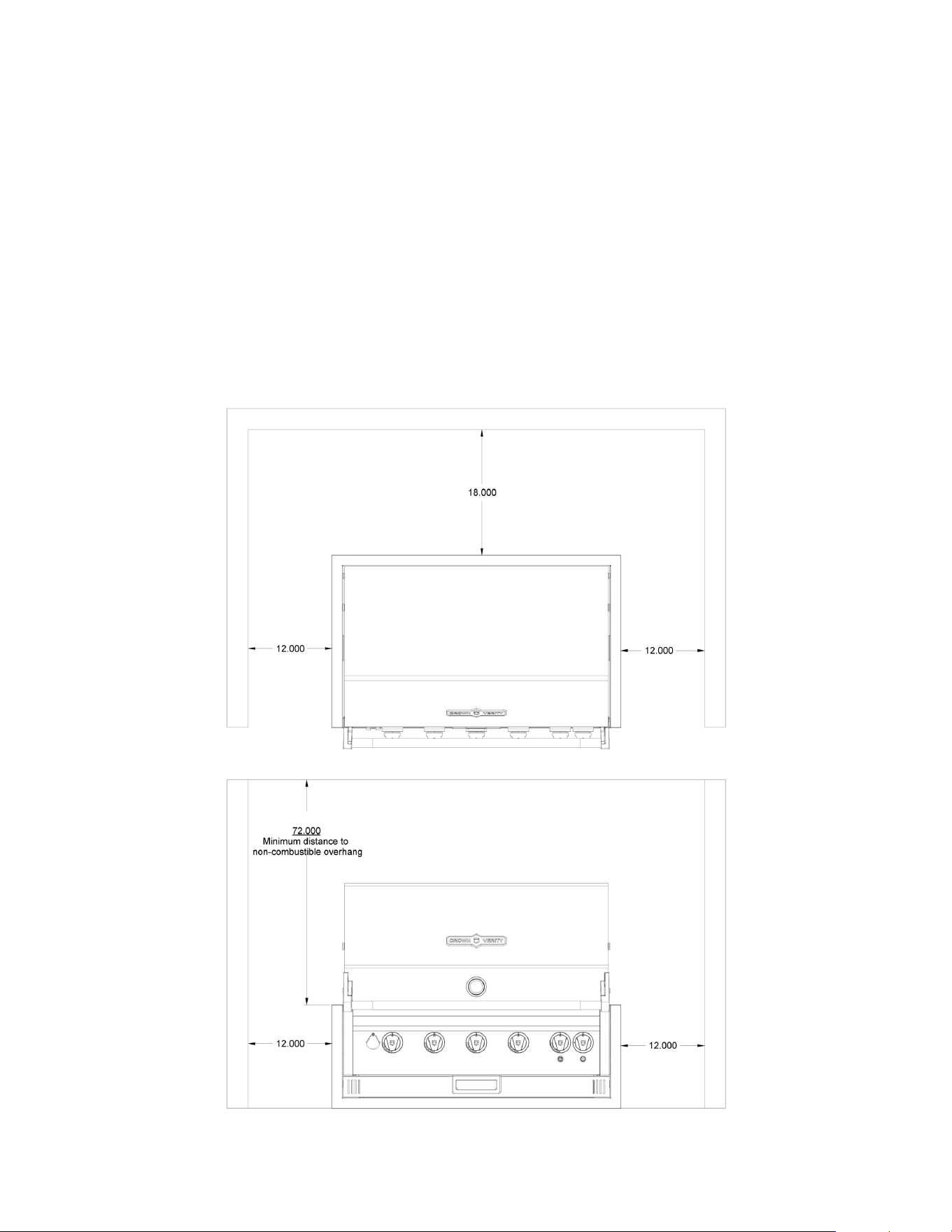
CLEARANCE TO COMBUSTIBLES
Minimum clearance from the sides and back of the grill/side burner to adjacent construction
below and above the countertop surface is 12” from the sides and 18” from the back of the
hood.
A minimum of 12 inches (30.5 cm) clearance is required on the left and right side of the grill
above the countertop for the rotisserie motor and spit rod.
If the grill/side burner is to be placed into a combustible enclosure, an approved insulated
jacket is necessary and is available only through your Crown Verity dealer. Crown Verity
insulated jackets have been designed and tested specifically for your grill.
REAR HOOD CLEARANCE
A 3.5 inch (8.9 cm) clearance is required behind the rear flange of the grill to allow the hood to
open unobstructed. The grill exhausts combustion products and cooking greases to the back.
Do not locate the grill where this exhaust will be difficult to clean.
Page 15 of 69
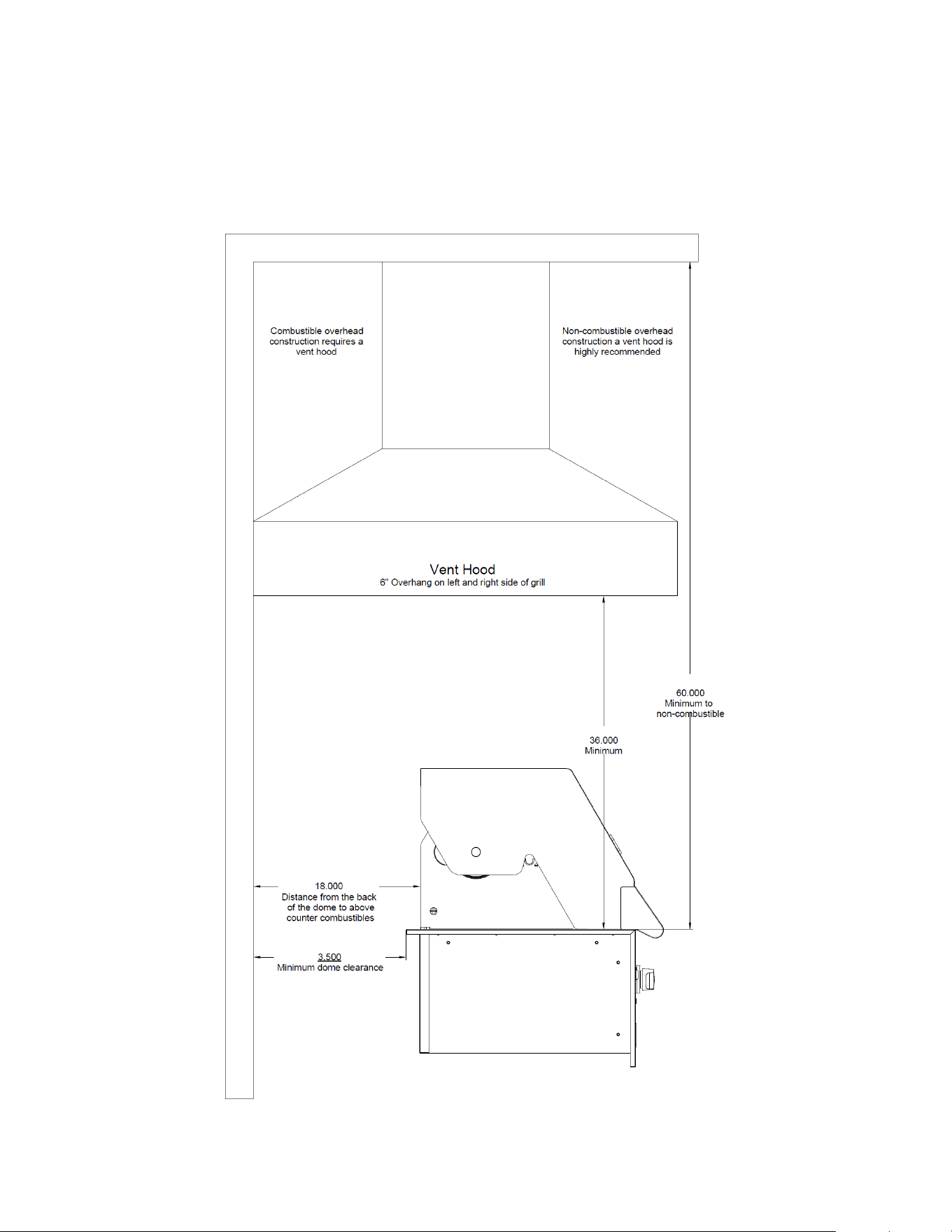
OVERHEAD PROTECTION AND EXHAUST REMOVAL
If installed under any combustible construction the cooking area over the grill/side burner
MUST be covered with an exhaust hood. The hood must provide 6 inches (15.2 cm) of overhang
on all exposed sides. The exhaust hood shall provide no less than 1,200 CFM for proper exhaust
ventilation. The hood must be approved for outdoor installation and provided with a dedicated
GFCI protected branch circuit (See “Figure 2” for further details).
FIGURE 1. CLEARANCES TO COMBUSTIBLES
IBI36 with IBI36FDLT Light Package Shown
All appliance covered by this manual are subject to the clearances shown in Figure 1.
Page 16 of 69
FIGURE 2. EXHAUST HOOD REQUIREMENTS
IBI36 with IBI36FDLT Light Package Shown
All appliance covered by this manual are subject to the clearances shown in Figure 2.

Page 17 of 69
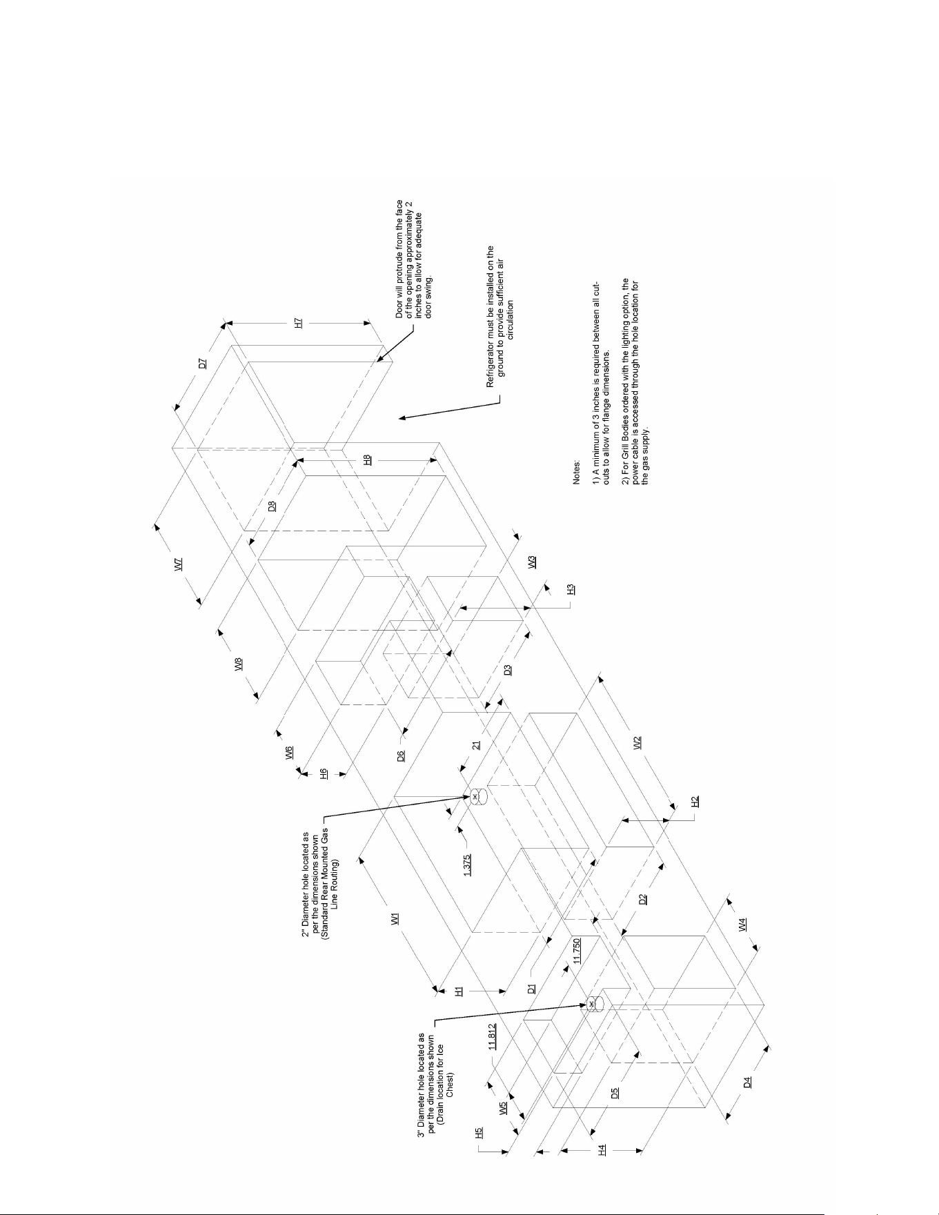
Built-In Cut-out Dimensions
This measurements and dimensions detailed below are designed to assist with planning your
outdoor kitchen. Due to continuing product innovation, specifications are subject to change
without notice. Please reference the Manual for details on gas plumbing requirements,
electrical specifications and the proper installation of your Crown Verity outdoor kitchen
equipment.
BUILT-IN SIDE BURNERS
H6
W6
D6
IBISB
13.000
15.750
23.000
(cm)
33.0
40.0
58.4
H8
W8
D8
IBISC-SB
33.000
19.125
24.750
(cm)
83.8
48.6
62.9
BUILT-IN STORAGE DRAWERS
H2
W2
D2
IBI30-DD
12.125
32.625
22.750
(cm)
30.8
82.9
57.8
IBI36-DD
12.125
38.625
22.750
(cm)
30.8
98.1
57.8
IBI42-DD
12.125
44.625
22.750
(cm)
30.8
113.3
57.8
IBI48-DD
12.125
53.125
22.750
(cm)
30.8
134.9
57.8
BUILT-IN STORAGE CABINETS
H4
W4
D4
IBILC
26.360
18.938
23.000
(cm)
67.0
48.1
58.4
IBISC
18.860
18.938
23.000
(cm)
47.9
48.1
58.4
BUILT-IN ICE CHEST
H5
W5
D5
CV-IC1
11.125
23.625
23.500
(cm)
28.3
60.0
59.7
BUILT-IN REFRIDGERATION
H7
W7
D7
CV-RF-1
33.750
24.000
22.000
(cm)
85.7
60.1
55.9
BUILT-IN GRILLS
H1
W1
D1
IBI30
13.000
33.000
23.000
(cm)
33.0
83.8
58.4
IBI36
13.000
39.000
23.000
(cm)
33.0
99.0
58.4
IBI42
13.000
45.000
23.000
(cm)
33.0
114.3
58.4
IBI48
13.000
53.375
23.000
(cm)
33.0
135.6
58.4
IBI482RD
13.000
53.375
23.000
(cm)
33.0
135.6
58.4
BUILT-IN SINK
H8
W8
D8
IBISC-SK
33.000
19.125
24.750
(cm)
83.8
48.6
62.9
BUILT-IN ACCESS DOORS
H3
W3
D3
IBI-VD
19.125
18.938
3.813
(cm)
48.6
48.1
9.68
H2
W2
D2
IBI30-HD
12.125
32.625
3.813
(cm)
30.8
82.9
9.68
IBI36-HD
12.125
38.625
3.813
(cm)
30.8
98.1
9.68
IBI42-HD
12.125
44.625
3.813
(cm)
30.8
113.3
9.68
IBI48-HD
12.125
53.125
3.813
(cm)
30.8
134.9
9.68
Page 18 of 69
FIGURE 3. REFERENCE DRAWING FOR CUT-OUT DIMENSIONS

Page 19 of 69
Gas Connections
WARNING: NEVER CONNECT A GAS LINE DIRECTLY TO THE GRILL/SIDE BURNER. A
PRESSURE RGULATOR MUST BE INSTALLED ON ALL GAS EQUIPMENT. ALL LOCAL CODES
REQUIRE IT AND CROWN VERITY SUPPLIES THE CORRECT REGULATOR WITH YOUR GRILL.
REMOVING OR FAILING TO INSTALL THE PRESSURE REGULATOR CAN RESULT IN FIRE AND
SERIOUS PERSONAL INJURY AND WILL VOID THE WARRANTY
.
IMPORTANT LP TANK SAFETY INFORMATION
Although safe to use when properly handled, careless handling of a propane gas
cylinder could result in fire, explosion and/or serious injury.
To avoid risk of fire, explosion or injury, take the following safety precautions:
WARNING:
For safety reasons, the LP gas cylinder, if supplied with your grill or side burner,
has been shipped empty. The cylinder must be purged of air and filled prior to use.
•
The LP-gas supply cylinder to be used must be constructed and marked in
accordance with the specifications for LP-gas cylinders, U.S. Department of
Transportation (DOT) or the National Standard of Canada for Cylinders, Spheres
and Tubes for the Transportation of Dangerous Goods, CAN/CSA-B339.
The LP gas cylinder used for this appliance must not have a capacity
exceeding 20 lb. (9 kg). Approximately 18” (46cm) high and 12”
(31cm) diameter
All LP gas cylinders used with this appliance must be provided with a
shutoff valve terminating in a cylinder valve outlet No. 510, specified
in the Standard for Compressed Gas Cylinder Valve Outlet and Inlet
Connection (USA) ANSI/CGA-V-1-1977 (Canada) CSA B96.
The cylinder supply system must be arranged for vapor withdrawal.
The cylinder must include a collar to protect the cylinder valve.
The cylinder must be installed as per assembly instructions.
Never fill the cylinder beyond 80% full. A fire causing death or
serious injury may occur.
The cylinder valve must include a safety relief device having direct
communication with the vapor space of the cylinder.
•
Never use dented, rusted, or damaged propane cylinders.
•
Allow only a qualified LP gas dealer to fill or repair cylinders.

Page 20 of 69
•
A liquid propane cylinder should never be “overfilled” beyond the cylinder filling
capacity. “Overfilling may create a dangerous condition. “Overfilled” tanks can
build up excess pressure. The standard safety device on tanks is the safety relief
valve. This valve vents propane gas vapors to relieve excess pressure. These vapors
are combustible and can be ignited.
•
Make sure the gas dealer checks the cylinder for leaks after filling.
•
Do not store spare LP gas cylinders under the grill.
•
For built-in cooking gas appliances with a connection to a self-contained 20 or 30
lbs. LP tank, the design lay-out can only accommodate storage for the LP tank
currently in use. The design cannot accommodate the storage of a spare tank
vertically or horizontally within any enclosure, or under the firebox of the
appliance.
•
Always use the protective cap provided with your cylinder whenever it is
not connected to your grill.
•
Never connect the grill to anything other than the fuel source indicated on
the rating plate. Conversions are available for switching fuel sources.
Contact Crown Verity or an authorized dealer for details. Conversion
installation must be done by a licensed gas technician.
•
The LP-gas cylinder must include a collar to protect the cylinder valve from
damage.
•
Ensure proper ventilation of the cylinder. The cylinder supply system must
be arranged for vapor withdrawal.
•
When the grill/side burner is not in use, the gas must be turned off at the
supply cylinder.
•
Handling, storage and transportation of propane cylinders must be in
accordance with Storage and handling of Liquid Petroleum Gases,
ANSI/NFPA 58 or Natural Gas and Propane Installation Code, CSA B149.1
•
The grill/side burner may be stored indoors, but only if the cylinder is
disconnected and removed from the oven. An LP cylinder MUST NEVER BE
STORED INDOORS.
•
Cylinders must be stored outdoors and must not be stored in a building,
garage, or any other enclosed area. Store in a well-ventilated area.
•
Do not store in the vicinity of any gas burning apparatus or in any high heat area
such as a closed car or trunk.
•
Do not smoke while transporting a LP cylinder in your vehicle.
•
Always close the main valve on the tank before disconnecting or transporting the
tank.
•
Transport and store cylinders in an upright position. Do not tip it on its side
•
The pressure regulator and hose assembly supplied with the grill must be used.
Page 21 of 69
Replacement pressure regulators and hose assemblies must be the type specified
by Crown Verity and installed by a licensed gas technician. For replacement parts,
contact Crown Verity Customer Service at 1-888-505-7240.
NOTE TO GAS TECHNICIAN
WARNING: DO NOT perform any pressure tests on this appliance or the regulator supplied in
excess of 1/2 PSIG.
For fixed fuel supply systems. RE: Pressure tests
1.
The appliance and its individual shut-off valve must be disconnected from the gas supply
piping system during any pressure testing of that system at test pressures in excess of 1/2
psi. (3.45 kPa).
2.
The appliance must be isolated from the gas supply piping system by closing its individual
manual shut-off valve during any pressure testing of the gas supply piping system at test
pressures equal to or less than 1/2 psi. (3.45kPa).
WARNING: DO NOT install any gas handling components/materials affected by elevated
temperatures within 18 inches (45.7 cm) of any side of this appliance.
Make sure that the supply line is of adequate capacity to accommodate the higher inputs of the
grill before you begin. They are significantly higher inputs than average appliances of this type.
The use of a typical corrugated metallic appliance connector is recommended for connecting
the appliance, with a minimum inside diameter of 3/4”.
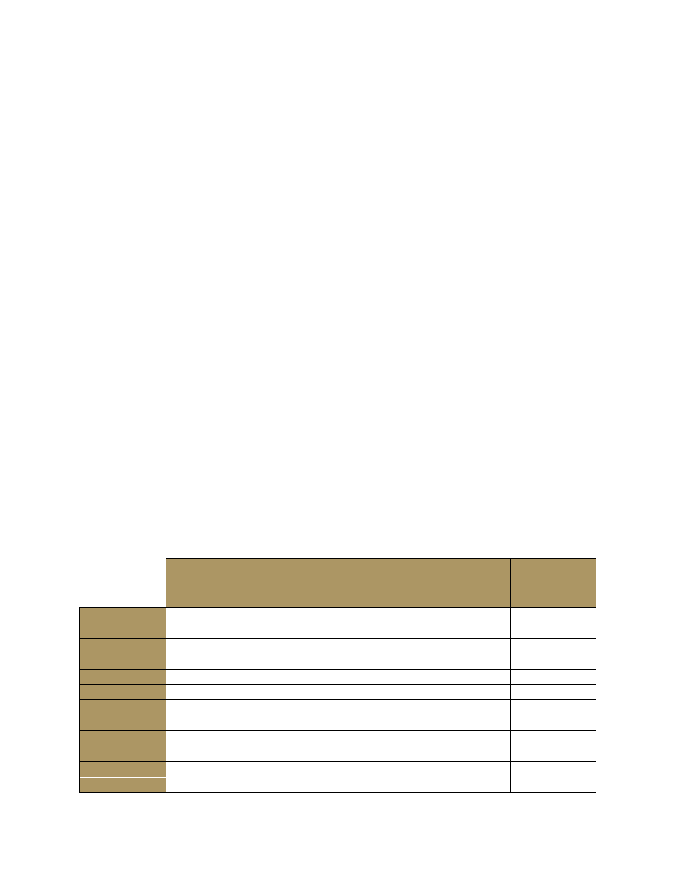
BTU Grills: Table 1
BTU’s
LP Pilot
Orifice - 70
BTU’s
LP Burner
Orifice - 58
BTU’s
NG Pilot
Orifice - 57
BTU’s
NG Burner
Orifice - 51
Total BTU’s
NG/LP
IBI30
5,500
14,750
5,500
14,750
64,500
IBI36
5,500
14,750
5,500
14,750
79,250
IBI42
5,500
14,750
5,500
14,750
94,000
IBI48
5,500
14,750
5,500
14,750
108,750
IBI482RD
5,500
14,750
5,500
14,750
94,000
IGM24
5,500
14,750
5,500
14,750
49,750
IGM36
5,500
14,750
5,500
14,750
79.250
IGM42
5,500
14,750
5,500
14,750
94,000
IE30
5,500
14,750
5,500
14,750
64,500
IE36
5,500
14,750
5,500
14,750
79,250
IE42
5,500
14,750
5,500
14,750
94,000
IE36I (GRILL)
5,500
14,750
5,500
14,750
79,250
Page 22 of 69
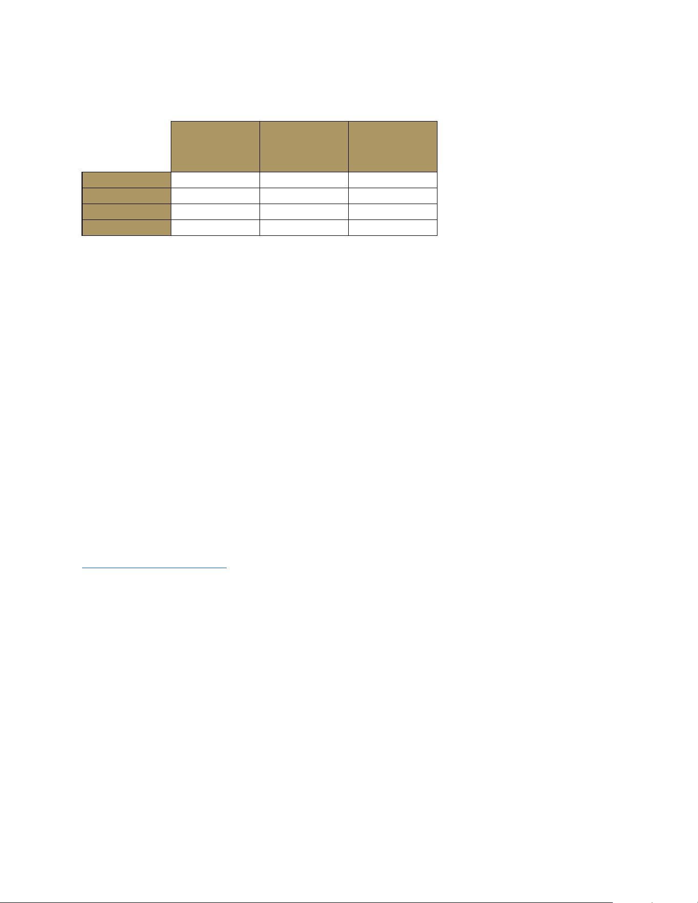
BTU Side Burners: Table 2
BTU’s
LP Burner
Orifice - 58
BTU’s
NG Burner
Orifice - 52
Total BTU’s
NG/LP
IBISB
12,000
12,000
24,000
IBISC-SB
12,000
12,000
24,000
ICM-SB
12,000
12,000
24,000
IE36I (SB)
12,000
12,000
24,000
Note: For LP (Liquid Propane) applications, the specified BTU’s are calculated at a
manifold pressure of 11 inches W.C.. For NG (Natural Gas) applications, the specified
BTU’s are calculated at a manifold pressure of 4 inches W.C..
For reference, orifice sizes and manifold pressures are indicated on the rating plate
of the appliance (See Appendix “A” for further details).
You are encouraged to explain any provisions or concerns you may have regarding the
placement of the equipment near or within the supporting structure and the
surroundings. Please forward any suggestions you may have should the gas supply
components pose any aesthetic problems that the property owner may be concerned
with before you begin.
IMPORTANT:
M
ake sure the owner knows where the main gas supply shut off valve is
located. For safety and for proper use & care, you must leave this manual with the
owner. Make sure you advise them to keep it for future reference. For technical
assistance call
the Crown Verity customer service desk at: 1-888-505-7240 or
service@crownverity.com
LIQUID PROPANE GAS REQUIREMENTS (20 and 30 POUND CYLINDERS)
Verify the type of gas your grill/side burner has been configured for by the factory by
checking the rating plate (See Appendix “A” for further details). Grills and side burners
configured for liquid propane (LP) gas are orificed differently than appliances
configured for natural gas (NG). Grills and side burners configured for use with 20 or 30
pound LP cylinders (Type 1) are shipped with an LP regulator hose assembly attached.
They also include a pull-out propane drawer and a label affixed to the outside surface
of the cabinet door stating ““FUEL CYLINDER SHUTOFF VALVE BEHIND THIS DOOR”.
This label is a requirement of the Gas Food Service Equipment standards ANSI
Z83.11/CSA 1.8 2016. This label is only required for commercial applications; for
residential applications, the label can be removed.

Page 23 of 69
WARNING: Grills with a total BTU’s output less than 80,000 BTU’s can only be
connected to 20 lbs. propane cylinders (See Table1 and 2 for BTU requirements).
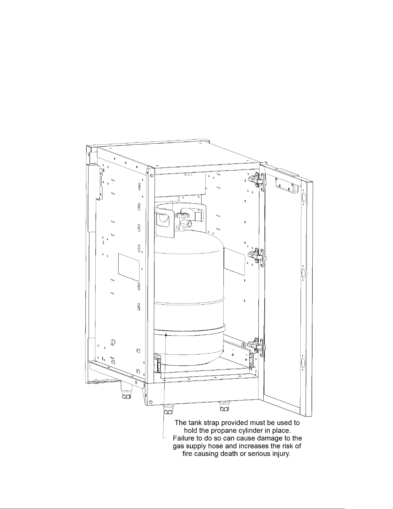
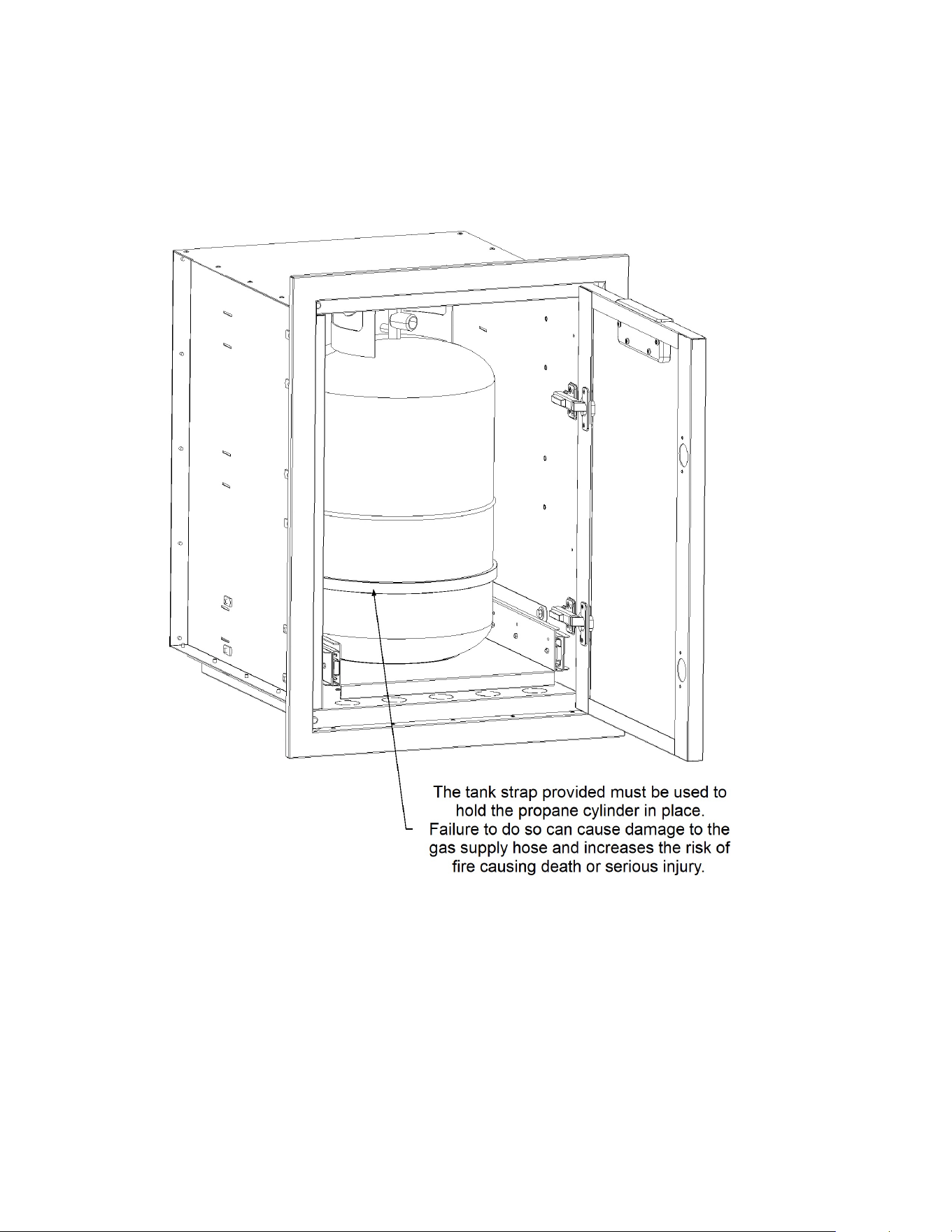
WARNING:
The propane tank strap provided must be used to hold the propane
cylinder in place. Failure to do so can cause damage to the gas supply hose and
increases the risk of fire causing death or serious injury (See “Figures 4-6”) for further
detail.
For built-in applications, not using a Crown Verity built-in cabinet, the propane
cylinders must be integrally mounted. An integral mounting means shall be provided
on the outdoor cooking gas appliance for mounting the LP gas supply cylinder(s).
Integral retention means shall be provided on the outdoor cooking gas appliance to
limit the movement of the LP gas cylinder(s). Lateral movement shall not exceed 1 in
(25.4 mm) at the retention means, and the cylinder(s) or any portion thereof shall not
become dislodged from its (their) retention means when a lateral force equal to the
full weight of the cylinder(s) is applied in any direction at the center of the vertical
height of the cylinder(s). If the means is for attachment to the protective collar of the
cylinder(s) it shall not interfere with the operation of the cylinder(s) valve(s). Any
movement shall not transmit strain to rigid tubing or pipe connections. Mounting and
retention means shall incorporate adequate adjustments to accommodate the size of
the cylinder(s) specified by the manufacturer.
WARNING:
For Pr
opane Gas Models: Your grill/side burner is designed to operate on L.P.
(propane) gas pressure regulated at 11” water column. The regulator(s) supplied with the grill
are set to this pressure and must be used.
Connection:
The Type I (Q.C.C.1) cylinder valve is recognizable by the large external thread on
the outlet part of the valve. Standard valves do not have these exterior threads. Any attempt to
fit the regulator(s) with anything other than the mating Type I (Q.C.C.1) connector, (recognized
by the large plastic features designed into the Type I (Q.C.C.1) system. Fitting a standard #510
P.O.L connector, will not provide the flow control or temperature shut-off safety features built
into the complete Type I (Q.C.C.1) system. This regulator is equipped with the Type I (Q.C.C.1),
quick closing connection system, which incorporates the following features:
• Will not allow gas to flow until a positive seal has been made.
• Has a thermal element that will shut off the flow of gas if subjected to temperatures
between 115° and 150°C (240° & 300°F).
• Has a flow limiting device which, when activated, will restrict the flow of gas to 10 cubic feet
per hour (25000 BTUs). It activates each time you open the cylinder valve, so be sure the
appliance is turned OFF before you open the valve. If the appliance is not turned OFF when
you open the valve, the Flow Limiting Device will not be able to reset and will restrict gas
flow to the appliance.
Page 24 of 69
FIGURE 4. LP TANK RETENTION STRAP-GRILL/SIDE BURNER CABINET
To connect the LP regulator hose assembly to the LP tank, first make sure the main
valve on the tank is completely closed. Make sure also that the control valves on the
grill are OFF. Thread the regulator inlet over the tank valve. Use care to ensure proper
alignment of the threaded coupler and avoid cross-threading or damaging the coupler.
Turn the coupler clockwise until tightened up, but do not over-tighten.
Page 25 of 69
After connecting a fresh LP tank, you may need to purge air from the system. Before
lighting, open the main valve on the tank. Turn one of the burner control valves on the
grill/side burner to the HIGH position for about 15 seconds to purge air from the
system. Turn the control valve on the grill OFF and wait 5 minutes for any gas to clear.
Finally, continue with the normal lighting procedure.
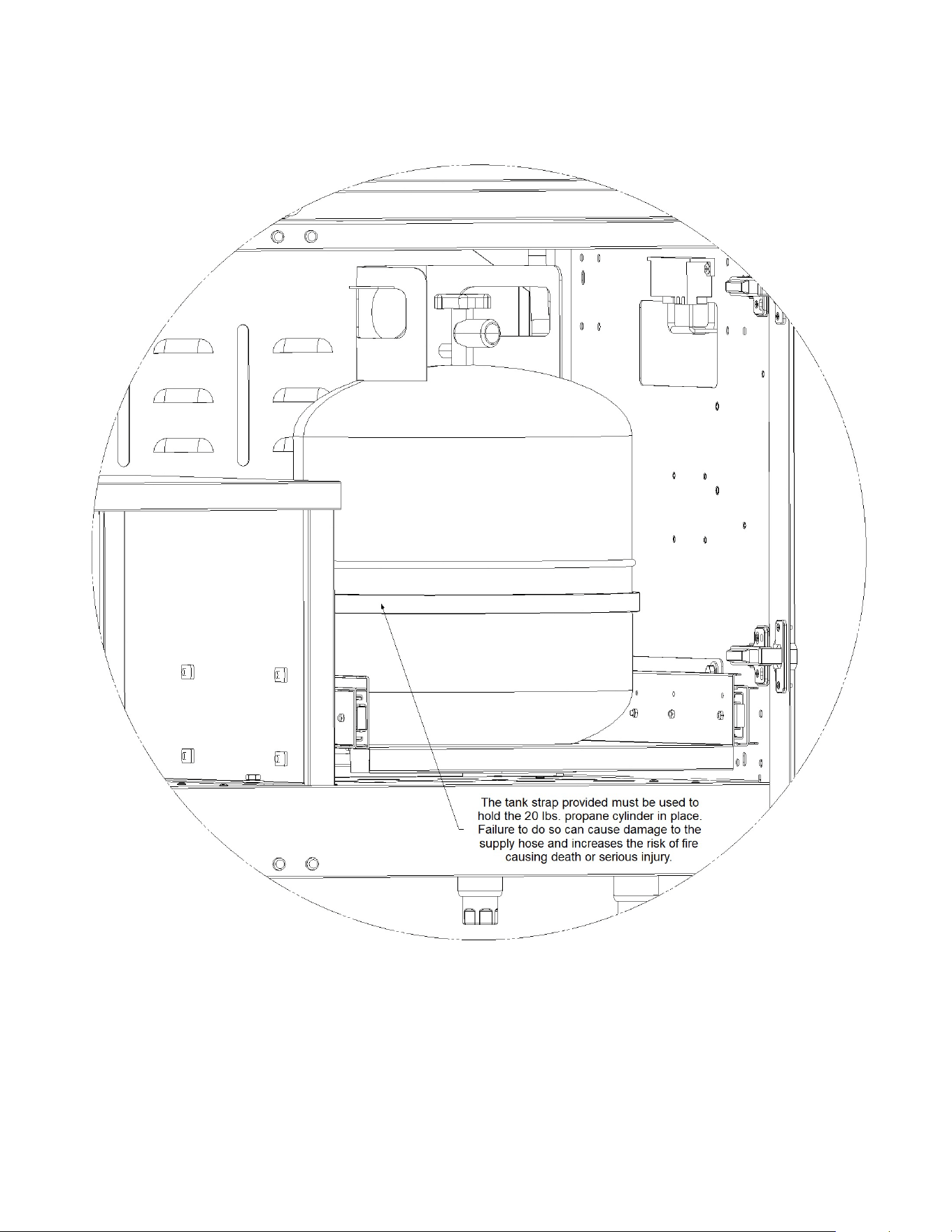
FIGURE 5. LP TANK RETENTION STRAP-BUILT-IN STORAGE CABINET.
NOTE: 30 LBS. TANK SHOWN CAN ONLY BE USED WITH GRILLS THAT
HAVE A BTU CAPACITY EQUAL TO OR GREATER THAN 80,000 BTU’s.
Page 26 of 69
TROUBLESHOOTING:
If the large thermally sensitive coupling nut is exposed to
temperatures above 115°- 150°C
(240° & 300°F)
it will soften and allow the regulator
probe to Disengage from the cylinder valve, thereby shutting off the flow of gas.
Should this occur, do not attempt to reconnect the nut. Remove the entire regulator
assembly and replace it with a new one. The cause of the excessive heat should be
determined and corrected before operating the grill/side burner again.
The regulator probe also contains a flow-sensing element, which will limit the flow of
gas to the regulator to a manageable amount (10 cubic feet per hour) in the event of a
FIGURE 6. LP TANK RETENTION STRAP-MODULAR STORAGE CABINET.
NOTE: 30 LBS. TANK SHOWN CAN ONLY BE USED WITH GRILLS THAT
HAVE A BTU CAPACITY EQUAL TO OR GREATER THAN 80,000 BTU’s.
Page 27 of 69
hose or regulator failure, or a leak. If it is evident that the flow-limiting device has
activated, the cause of the excessive flow should be determined and corrected before
using your grill/side burner again.
Improper lighting procedures can also cause the flow-limiting device to activate,
resulting in reduced heat output. If this is suspected, shut off all burner controls and
cylinder valve, and carefully repeat lighting instructions step by step. Do not remove
the nut and probe and do not attempt to connect to anything other than a mating
Type I (Q.C.C.1) cylinder valve.
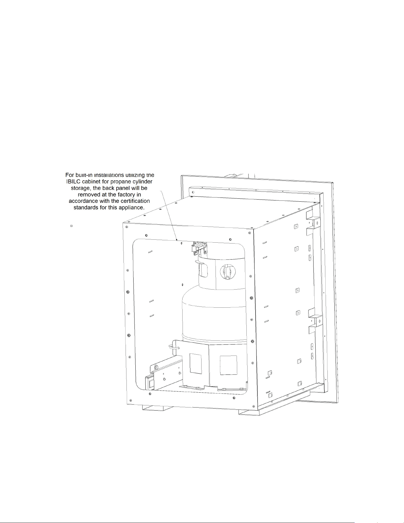
IMPORTANT:
When installing the Crown Verity built-in cabinet with propane storage,
the bottom of the cabinet there must be a minimum clearance of 2 in (50.8 mm)
between the floor of the LP gas cylinder enclosure and the ground.
FIGURE 7. VENTILATION REQUIREMENTS FOR BUILT-IN CABINETS
WITH PROPANE CYLINDER STORAGE.
Page 28 of 69
WARNING: ENCLOSURE REQUIREMENTS FOR BUILT-IN GRILLS AND ACCESSORIES
FOR YOUR SAFTEY
, if not using a Crown Verity propane enclosure for a built-in
application, you must provide the openings listed below for drainage, replacement air
flow and cross ventilation for any storage area exposed to possible leakage from gas
connections, the unit, or propane cylinders:
One side of the gas cylinder enclosure left completely open to the outside or by
providing four (4) ventilation openings. Two (2) openings are to be at the cylinder
valve level (approximately 16 inches (40.6 cm) above the floor) and on opposite walls
of the enclosure. Two (2) more openings must be at the floor level on opposite sides
of the enclosure. The floor level opening must start at the floor and shall extend no
higher than 5 inches (12.7 cm) above the floor. Each opening shall have a minimum of
10 square inches (64.5 cm²) of free area. To achieve the proper ventilation, you may
drill a series of holes, or omit grout from masonry joints, or replace a brick with a
hardware cloth screen. If the floor of the cabinet is raised and the space beneath the
cabinet is open to the outside, the lower ventilation openings may be in the floor.
Doors on any propane enclosure must be non-locking.
The design of the outdoor built-in propane enclosure must provide adequate access so
that the LP gas cylinder can be connected, disconnected, and the connections
inspected and tested outside the cylinder enclosure. Consult you gas supplier for
venting and regulatory requirements when connecting to household propane supply.
DANGER:
A. Never connect a propane appliance to an unregulated propane gas supply
or other gas type.
B. Do not attempt to alter the hose or regulator in any way.
C. Do not allow the hose to come in contact with any hot surfaces of the grill.
D. Visually inspect the entire length of the hose assembly before each use for
any evidence of damage (cuts, cracks, burns) or excessive wear. If found,
replace the assembly before using your grill.
E. The connection fitting must be protected when disconnected
from the LP cylinder. If the fitting is allowed to drag on the
ground, damage to the fitting may occur resulting in leaks or an
incomplete connection. Dirt could also enter the small inlet hole,
blocking gas flow completely.

Page 29 of 69
The gas supply hose portion must be readily visible across its entire length for
inspection. Removal or opening of an access plate(s) or door(s) without the use of tools
for inspection purposes is considered acceptable.
A gas appliance pressure regulator shall be installed in a location so that it will not
attain a temperature in excess of that specified by the regulator manufacturer as
determined during conduct of Clause 5.14, Wall, floor, and component temperatures,
or Clause 5.21.5, as applicable per Standard ANSI Z83.11/CSA 1.8. On a built-in unit,
the gas appliance pressure regulator shall be installed in a location where pressure
adjustments can be made from the front when the appliance is in a normally installed
position.
The vent of any fuel cylinder regulator must be protected from adverse weather.
The regulator used on the self-contained LP-gas supply system shall be in a location
such that it will not attain a temperature above 140°F (60 °C) when tested in
accordance with Clause 5.14, Wall, floor, and component temperatures
per Standard
ANSI Z83.11/CSA 1.8.
NATURAL GAS REQUIREMENTS
Verify the type of gas your grill/side burner has been configured for by the factory by
checking the rating plate on the appliance (See Appendix “A” for further details).
Grills
and side burners configured for natural gas (NG) are orificed differently than units
configured for liquid propane (LP) gas. Appliances configured for use with natural gas
are shipped with a regulator fitted with a 3/4 inch flare fitting for the inlet connection.
For the mobile, Non-Modular Grill models, IE30, IE36,IE42 and IE36I, the regulator is
positioned inside the cabinet on the right hand back rear corner. The grills are
equipped with a with a 10 foot hose, regulator and quick-connect fitting
(See “Figure 8” for installation details).
For fixed modular grill and side burner models, IGM24, IGM36, IGM42 and ICM-SB, the
regulator is positioned inside the cabinet on the right hand back rear corner. The
regulator is fitted with a 3/4 inch male flare fitting and the certified gas installer will
connect the gas supply at this fitting (See “Figure 8” for installation details).
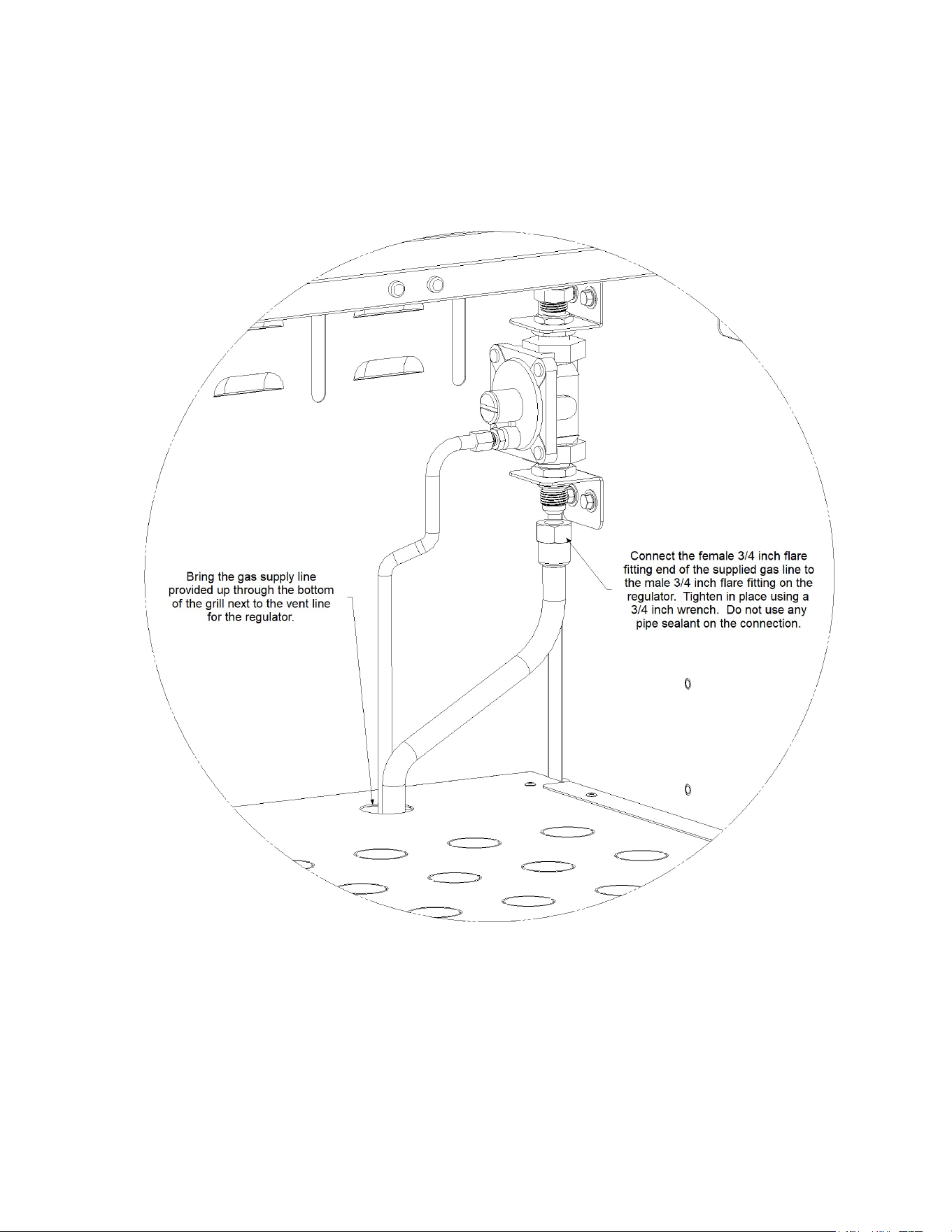
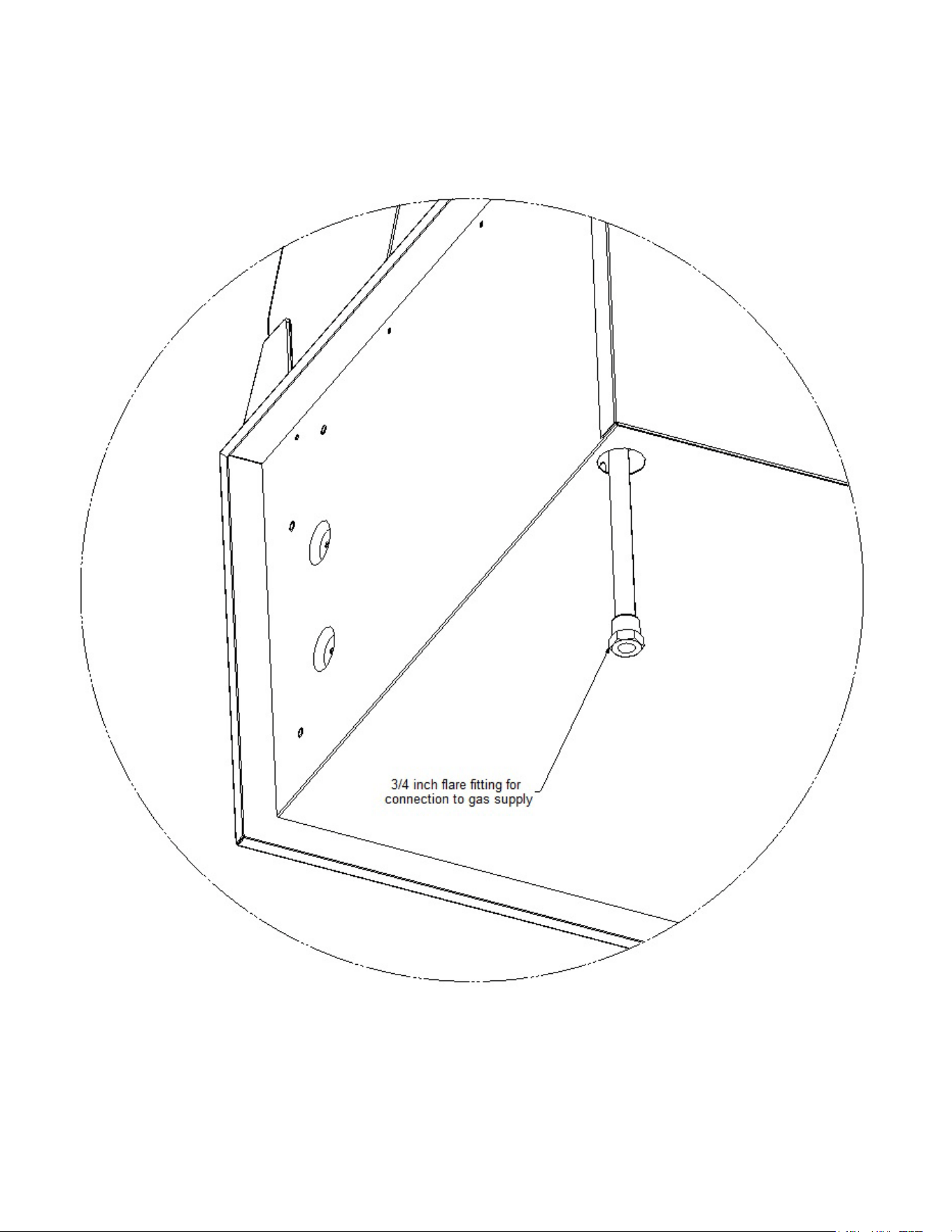
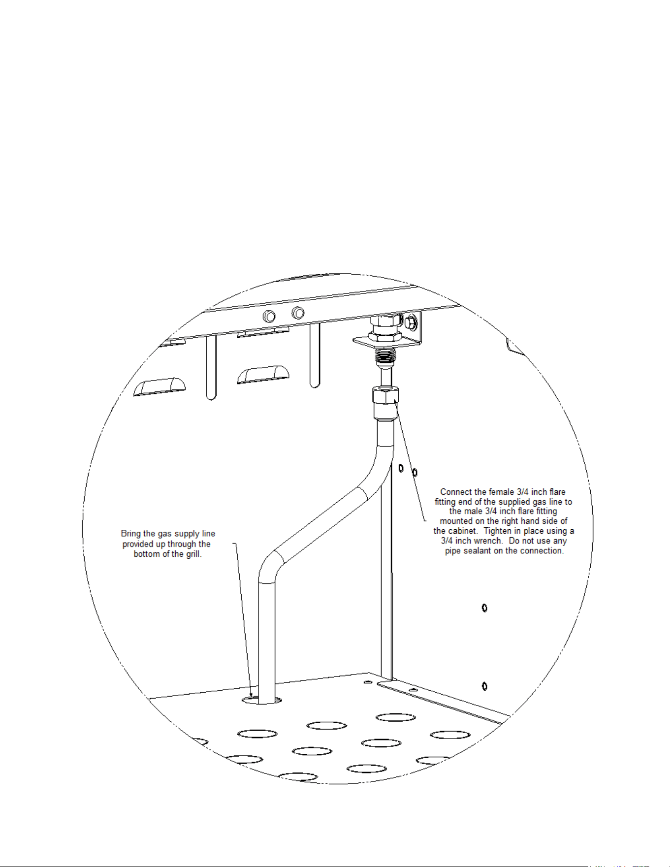
For Built-In grills and side burners, the regulator is provided separately. The appliances
are equipped with a 1/2 O.D. corrugated gas line with a 3/4 inch female flare fitting.
The connection to the regulator and gas supply must be done in accordance with this
manual and completed by a certified gas technician (See “Figure 9” for further details).
Page 30 of 69
FIGURE 8. NATURAL GAS CONNECTION FOR FIXED MODULAR AND NON-
MODULAR MOBILE GRILLS AND SIDE BURNERS
Page 31 of 69
WARNING:
For Natural
Gas Models: Your appliance is designed to operate on natural gas (NG)
pressure regulated at 4” water column. The regulator supplied with the grill is set to this
pressure and must be used.
FIGURE 9. NATURAL GAS AND BULK PROPANE CONNECTION FOR BUILT IN GRILLS
AND SIDE BURNERS

Page 32 of 69
•
In no case should an inlet pipe less than 3/4” inside diameter or 1” outside
diameter ever be used to connect this product.
•
Calculate the total BTU output of all equipment and refer to (See Appendix “B” for
further details) for allowable run distances for 3/4 inch pipe. Failure to meet these
minimum requirements may reduce performance of the grill and any other
appliances running on that supply line.
•
Always keep supply line runs as short as possible. (See “Tables 1 and 2” for specific
model BTU outputs)
•
A gas shut-off valve must be installed in an easily accessible location by a qualified
gas technician.
•
Do not use threading compound on any flare fittings.
IMPORTANT:
Always close the gas supply shutoff valve before disconnecting the appliance’s
gas supply hose.
IMPORTANT:
An installer-supplied safety shutoff valve MUST be installed on the natural gas
supply line for the grill/side burner. The valve should be easily accessed and located between 3
and 20 feet (1 to 6 m) away from the appliance (always check with local codes for specified
clearances and distances). All gas connections should be made by a licensed technician. The
installation and all installer-supplied parts must conform to local codes. In the absence of local
codes, the installation and all parts should conform to the National Fuel Gas Code, ANSI Z223.1/
NFPA 54 or Natural Gas and Propane Installation Code, CSA B149.1.
IMPORTANT:
Diameter and length of the gas supply pipe may limit the pressure and BTU
delivery of gas to the oven. The installer must ensure proper delivery to the appliance or it will
not operate properly (See “Appendix B” for further details). The appliance and its individual
shutoff valve must be disconnected from the gas supply piping system during any pressure
testing of that system at pressures in excess of 1/2 psi (3.5 kPa). During any pressure testing of
the gas supply piping system at test pressures equal to or less than 1/2 psi (3.5 kPa), the
appliance must be isolated from the system by closing its individual manual shutoff valve.
IMPORTANT:
Never run flex hose behind the firebox, run the hose at an angle, straight down,
or out of the back.
All pipe sealants must be of an approved type
.
Page 33 of 69
BULK SUPPLY LIQUID PROPANE GAS REQUIREMENTS
Verify the type of gas your
grill/side burner
has been configured for by the factory by
checking the rating plate on the unit (See “Appendix A” for further details). Grills and
side burners configured for liquid propane (LP) gas are orificed differently than units
configured for natural gas (NG). For
appliances
configured for use with bulk LP tanks, a
regulator is not supplied. To purchase these options, please contact Crown Verity at
1-888-505-7240.
FIGURE 10. BULK PROPANE CONNECTION FOR FIXED MODULAR AND
NON-MODULAR MOBILE GRILLS AND SIDE BURNERS

Page 34 of 69
For the mobile, Non-Modular Grill models, IE30, IE36,IE42 and IE36I, the gas supply
connection is positioned inside the cabinet on the right hand back rear corner. The
grills are equipped with a with a 10 foot (3 m) hose and quick-connect fitting. The
regulation of gas from the bulk tank must be adjusted to 11.0 inches W.C., refer to the
appliances rating plates in appendix “A” (See “Figure 10” for installation details).
For fixed modular grill and side burner models, IGM24, IGM36, IGM42 and ICM-SB, the
gas connection is positioned inside the cabinet on the right hand back rear corner. The
connection is fitted with a 3/4 inch male flare fitting and the certified gas installer will
connect the gas supply at this fitting. The regulation of gas from the bulk tank must be
adjusted to 11.0 inches W.C., refer to the appliances rating plates in appendix “A” (See
“Figure 10” for installation details).
For Built-In grills and side burners, the regulator is provided separately. The appliances
are equipped with a 1/2 O.D. corrugated gas line with a 3/4 inch female flare fitting.
The connection to the regulator and gas supply must be done in accordance with this
manual and completed by a certified gas technician. The regulation of gas from the
bulk tank must be adjusted to 11.0 inches W.C., refer to the appliances rating plates in
appendix “A” (See “Figure 9” for further details).
WARNING:
The Operating Pressure of the appliance is 11.0" W.C. A step-down regulator MUST
be used on an LP house system to reduce the pressure down to 11.0" W.C. for the grill.
IMPORTANT:
Always close the gas supply shutoff valve before disconnecting the appliance’s
gas supply hose.
IMPORTANT:
An installer-supplied safety shutoff valve MUST be installed on the liquid
propane gas supply line for the appliance. The valve should be easily accessed and located
between 3 and 20 feet (1 to 6 m) away from the oven. All gas connections should be made by a
licensed technician. The installation and all installer-supplied parts must conform to local codes.
In the absence of local codes, the installation and all parts should conform to the National Fuel
Gas Code, ANSI Z223.1/ NFPA 54 or Natural Gas and Propane Installation Code, CSA B149.1.
IMPORTANT:
Diameter and length of the gas supply pipe may limit the pressure and BTU
delivery of gas to the unit. The installer must ensure proper delivery to the appliance or it will
not operate properly
(See Appendix “B” for further details).
The appliance and its individual
shutoff valve must be disconnected from the gas supply piping system during any pressure
testing of that system at pressures in excess of 1/2 psi (3.5 kPa). During any pressure testing of
the gas supply piping system at test pressures equal to or less than 1/2 psi (3.5 kPa), the
appliance must be isolated from the system by closing its individual manual shutoff valve.
All pipe sealants must be of an approved type
.

Page 35 of 69
Gas Conversion Kits
Gas conversion kits are available from Crown Verity to allow the grill to operate on either
Natural gas or LPG. These kits should be installed by a qualified gas technician.
The kits come with complete installation instructions. These instructions should be read
completely and fully understood before installing the conversion kit.
Please contact the Crown Verity customer service desk at: 1-888-505-7240 or
service@crownverity.com for conversion kit requirements.
Leak Test Procedure
Although all gas connections on the
grill
are leak tested at the factory prior to
shipment, a complete test must be performed:
1.
After installation due to possible mishandling during shipping or installation.
2.
Periodic checks are also required every time the propane cylinder is refilled, any gas
component is changed or at least once a year.
3.
Immediately check for leaks if you smell gas.
WARNING: Never use an open flame to look for a leak. Perform the leak test outdoors in a
well-ventilated area. Extinguish all open flames and keep away from any heat or ignition
sources. DO NOT SMOKE! Use only a 50/50 mixture of liquid soap and water for leak testing.
IMPORTANT: Owners should only check for leaks on the gas connections that are external to
the grill. If the valves or other internal connections need to be checked, please call a licensed
technician or Crown Verity Customer Service at 1-888-505-7240.
For LP units using a 20 or 30 pound cylinder, a full cylinder should be used.
To Conduct the Test:
Make a soap solution of one part liquid dish soap and one part water. Make sure the
appliance
control valve(s) is in the OFF position. Turn the gas supply ON. Use a spray
bottle, brush or rag to apply the mild soap solution to all connections from the supply
line or LP cylinder to the connection on the rear of the
appliance
including the
following:
1.
Cylinder valve including the threads into the tank.
2.
All cylinder welds.
Page 36 of 69
3.
Regulator fitting(s) and cylinder connections.
4.
All hose connections.
Soap bubbles will appear at any connections with a leak. Turn OFF the gas supply and
tighten any leaky connections. Recheck, applying more mild soap solution.
Electrical Connections – For Appliances Equipped with a Lighting
Package
IMPORTANT: Do not use the appliance if any leaks cannot be stopped. Turn off
the gass supply valve, remove any gas cylinder and call a licensed gas appliance
service technician for proper repairs.
WARNING: ELECTRICAL GROUNDING
• Product installation must meet local electrical codes or, in the absence of local codes,
the latest edition of the National Electrical Code ANSI/NFPA No. 70 or the Canadian
Electrical Code Part 1, CSA 22.1.
• Use only a Ground Fault Interrupter (GFI) protected circuit with this outdoor cooking
gas appliance.
• This appliance is equipped with a three prong (grounding) electric plug for your
protection against shock hazard and must be plugged directly into a properly grounded
three prong outlets. Never cut or remove the grounding prong from this plug.
• Use only extension cords with a 3-prong grounding plug, rated for the power of the
equipment, and approved for outdoor use with a “W-A” marking.
• To protect against electric shock, do not immerse any part of the power cord, an
extension cord or any plugs in water or other liquid.
• Unplug the product from the outlet when not in use and before cleaning. Allow it to
cool before putting on or taking off parts.
• Do not let the cord hang over the edge of a table or touch hot surfaces.
• Do not use an outdoor cooking gas appliance for purposes other than intended.
• Do not operate any outdoor cooking gas appliance with a damaged cord, plug, or after
the appliance malfunctions or has been damaged in any manner. Contact the
manufacturer for repair.

Page 37 of 69
CONNECTION TO AC
Installation requires an outdoor 120VAC 15A GFI (Ground Fault Interrupter) electrical outlet
adjacent to the appliance. The GFI outlet features an internal breaker that reduces shock
hazard. This type of outlet should be installed by a qualified electrician either inside the island
enclosure for built-in units, or near the location where a free-standing unit will be used.
For built-in grills, the supplied 12VDC should be installed below the grill within the cabinet
enclosure. Select a location where the transformer is protected against water, heat and physical
damage.
When installing the transformer to the grill be careful to prevent the wiring and transformer
from contacting any hot surfaces behind or below the grill. It is recommended that the
transformer be located below the grill in a readily accessible location. Be sure to provide
adequate access to facilitate service if the transformer or connections should need future
maintenance.
If the electrical system fails to operate, a connection may have come loose in shipping or the
GFI may have tripped, requiring a reset.
Warning! Natural Hazard - Spiders
Spiders and other insects are
attracted by the smell of gas and
could make webs or nests in the
burners. This could partially or
completely block the flow of gas
through the venturis and is
indicated by a smoky, yellow
flame, and/or a burner that is
difficult or impossible to light.
Ultimately, it may cause the gas
to burn outside the venturis,
which can seriously damage your
grill. If this happens, immediately
shut off the propane at the
cylinder, or natural gas at the main shut-off valve. To prevent and/or correct this
occurrence, periodically check the venturis for obstructions by inserting a pipe cleaner
or flexible wire through the air inlet of the burner and twisting it. Ensure venturi tubes
are properly “seated” over the orifices after cleaning.

Page 38 of 69
IMPORTANT: The grill comes equipped with a thermometer. The thermometer
only measures the oven temperature which does not correlate directly with the
surface temperature of the grates. The grill thermometer may register a slightly
different temperature, so it is recommended that you familiarize yourself with the
temperature settings and your own personal cooking environment to optimize the
temperature setting for the best cooking performance.
General Operating Procedures
The
grill/side burner
reach operating temperatures in approximately 5-8 minutes but may
vary depending on environmental conditions. For compliance requirements, the temperature
gauge for the grill is specific to the air temperature. There is not a direct correlation between
the grill air temperature and the grate temperature, so the actual values will differ.
WHILE YOU ARE COOKING
The appliance surfaces get very hot as will the food you are cooking. Follow these tips while
operating the grill:
• Never leave the appliance unattended
• Never move the appliance while it is in use or when it is hot.
• The use of alcohol, prescription or non-prescription drugs may impair your ability to safely
operate the appliance.
• Do not touch the top of the appliance, the front shelf, or any surfaces inside or near the
door opening while the oven is hot. These surfaces can cause serious burns.
• Be very careful transporting any hot food items. They can cause serious burns to yourself or
those around you.
• Only use long-handled tools to clean the cooking surface. The handle must be long enough
that your hands stay safely outside of the appliance’s cooking surface.
• Never empty the grease/water tray while the unit is hot. The tray and its contents become
very hot while the grill is in use.
IMPORTANT: Practice with your grill to understand the temperature variables and
nuances of your unit before hosting your guests.

Page 39 of 69
Pre-Grill Checklist
BEFORE FIRST USE
A quick safety check should be performed before using your appliance for the first
time. Please ensure that:
1.
All packing materials and tie-downs have been removed from the appliance. (See
INDEX: “Unpacking & Assembly” for further details.)
2.
You have fuel connected. (See INDEX: “Gas Connections” for further details.)
3.
You have electric connected. (See INDEX:“
Electrical Connections – For Appliances
Equipped with a Lighting Package” for further details.)
4.
A qualified gas technician has performed a leak test on all the fittings that supply
fuel to your grill.
BEFORE EACH USE
A quick safety check should be performed before each time you use the grill (for your
safety).
1.
Clean and inspect the gas hose. If there is evidence of abrasion, wear, cuts, or leaks,
do not use the grill. The hose must be replaced prior to using the unit. Replace the
hose assembly with the exact type specified by Crown Verity.
2.
If you do not smell gas, shut everything off and have a qualified technician service
the appliance.
3.
Ensure the gas hose is clear of the appliance. Keep the fuel supply hose away from
any heated surface(s).
4.
Check that the area near the appliance is clear of combustible materials and vapors,
including alcohol, gasoline, aerosol containers and dry goods. Keep electrical cords
from being in contact with the unit.
5.
Do not use the appliance with overly loose-fitting clothing, especially loose sleeves
that may come in contact with the hot surfaces.
6. Never grill without the grease/water tray in place. Always ensure that the tray is pushed all
the way to the back and that you are keeping water in the tray. Failure to do so can cause a
fire.
7.
Grease is extremely flammable. Let the grease/water tray cool down before you attempt to
handle or dispose of its contents. The grease/water tray should be cleaned of grease on a
regular basis.
Page 40 of 69
AT EACH NEW SEASON
A quick safety check should be performed on the appliance if it has not been used for
an extended period of time (for your safety).
1.
Remove the grates and check the burners, shutters, orifices, and valves for
obstructions.
2.
Spiders and insects often nest in these areas of the grill and can disrupt air flow,
causing damage to the grill and personal injury.
3.
Clean and inspect the gas hose. If there is evidence of abrasion, wear, cuts or leaks,
do not use the grill. The hose must be replaced prior to using the unit. Replace the
hose assembly with the exact type specified by Crown Verity.
Lighting Your Grill
Before lighting your grill, be sure you have followed the instructions in this manual
regarding proper setup, placement, gas connections leak testing and safe operation, all
of which precede this page.
STANDARD LIGHTING PROCEDURE
•
Open roll dome so gas will not build up within the unit before lighting.
•
Make sure the main burner valves are in the OFF position (See “Figures 11 and 12”).
•
Turn the main gas supply on and wait 15 seconds.
•
For appliances equipped with a lighting package: Turn the pilot valve into the on position.
WARNING: BEFORE LIGHTING YOUR GRILL
•
Do not use the grill if the odor of gas is present at any time. Follow leak testing
procedures before using the unit.
• Always keep the lid open when lighting your grill.
• Releasing fuel into a closed grill before lighting will increase the risk of explosion,
property damage, personal injury or death.
• Keep your face and body as far from the grill as possible when lighting. Any time a
burner doesn’t light within 5 seconds, turn off the control, wait 5 minutes for gas to
dissipate, and repeat the lighting procedure.
• NEVER LEAVE THE GRILL UNATTENDED WHILE THE GRILL IS LIT.
Page 41 of 69
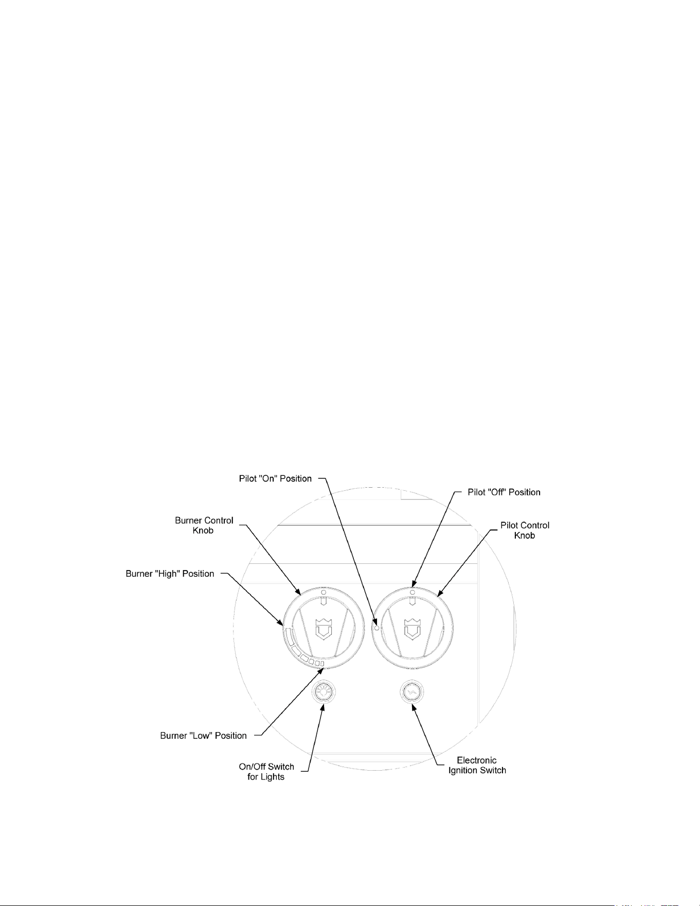
FIGURE 11A. VALVE POSITIONS GRILLS WITH LIGHT PACKAGE
Press down and hold the piezo ignition button (See “Figure 11”) to engage the electronic
ignition and light the pilot tube. Confirm that the pilot is lit by looking down through the
cooking grates. You will be able to feel heat coming up to the cooking surface also. (Do Not
touch the cooking grate while feeling for heat as the surface could cause burns)
•
For appliances not equipped with a lighting package: Turn the pilot valve into the on
position. Press down and hold the electronic ignition button (See “Figure 12”) to engage the
electronic ignition and light the pilot tube. Confirm that the pilot is lit by looking down
through the cooking grates. You will be able to feel heat coming up to the cooking surface
also. (Do Not touch the cooking grate while feeling for heat as the surface could cause
burns)
•
Once the pilot is lit, turn the main burner valves on to the desired temperature setting. (See
INDEX: “General Operating Procedures” for guidelines on how to determine ideal
temperature settings). Ignition should take place within 2 to 3 seconds. Verify that the
burners are lit by looking through the grates. If the burners do not light within this time,
turn knobs to the OFF position (See “Figures 11 and 12”) and wait 5 minutes for the gas to
dissipate before trying again. If the appliance will not light after multiple attempts, refer to
the troubleshooting section of this manual.
Page 42 of 69
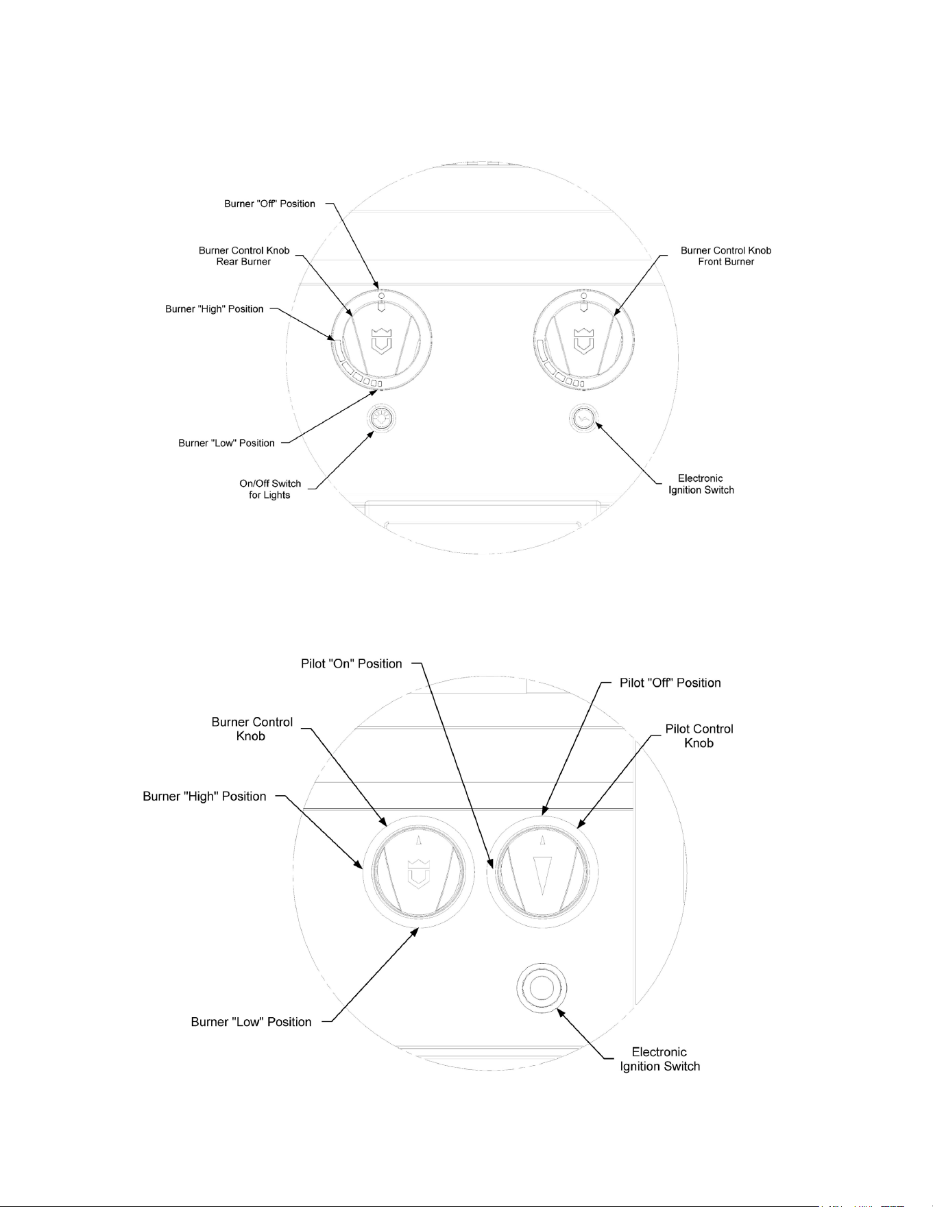
FIGURE 12A. VALVE POSITIONS GRILLS WITHOUT LIGHT PACKAGE
FIGURE 11B. VALVE POSITIONS SIDE BURNER WITH LIGHT
Page 43 of 69
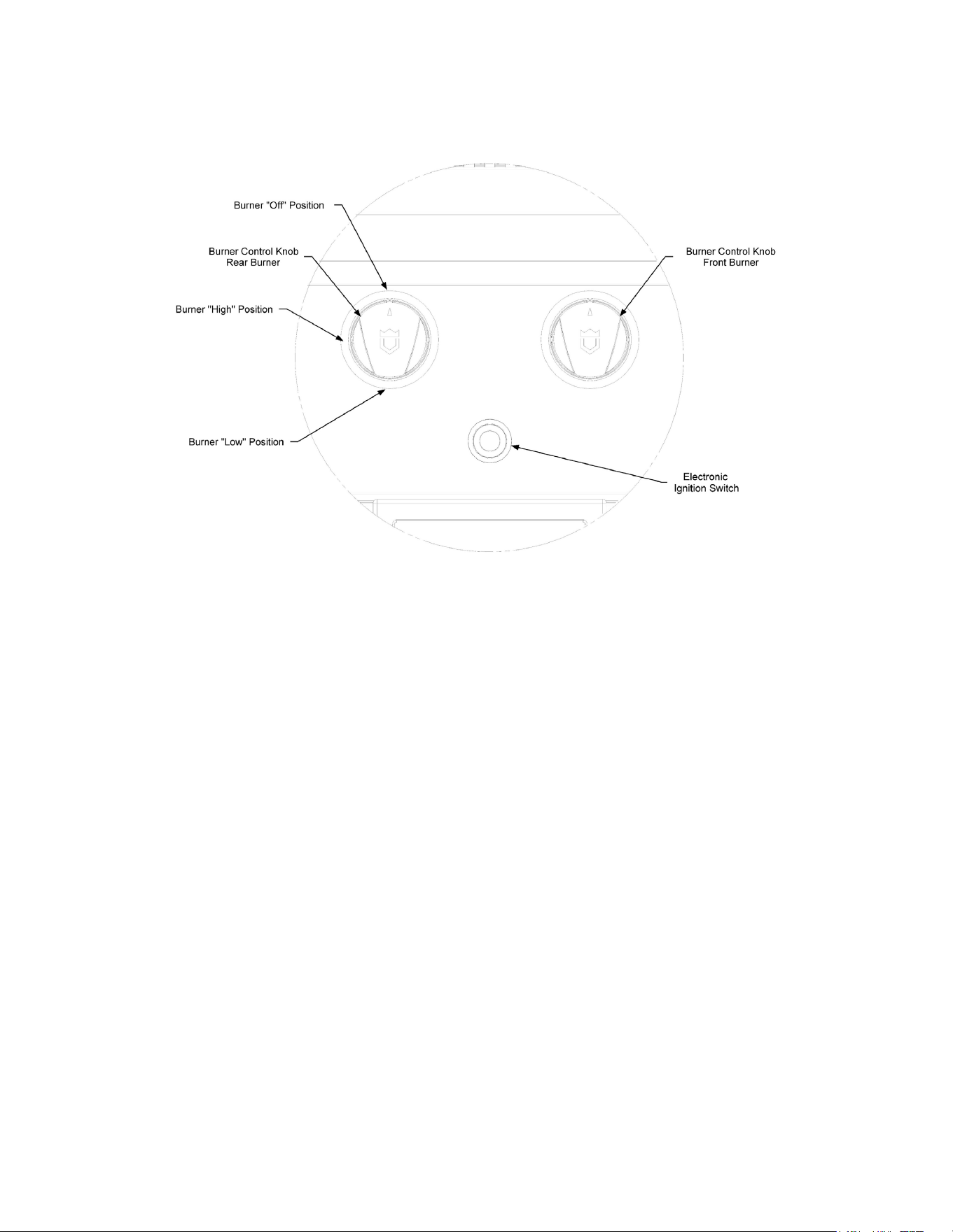
FIGURE 12B. VALVE POSITIONS SIDE BURNER WITHOUT LIGHT PACKAGE
MANUAL LIGHTING PROCEDURE:
•
Open the grill roll dome.
•
Make sure the main burner valve is the OFF position (See “Figures 11 and 12”).
•
Turn the main gas supply on and wait 15 seconds.
•
Turn the pilot valve to the on position.
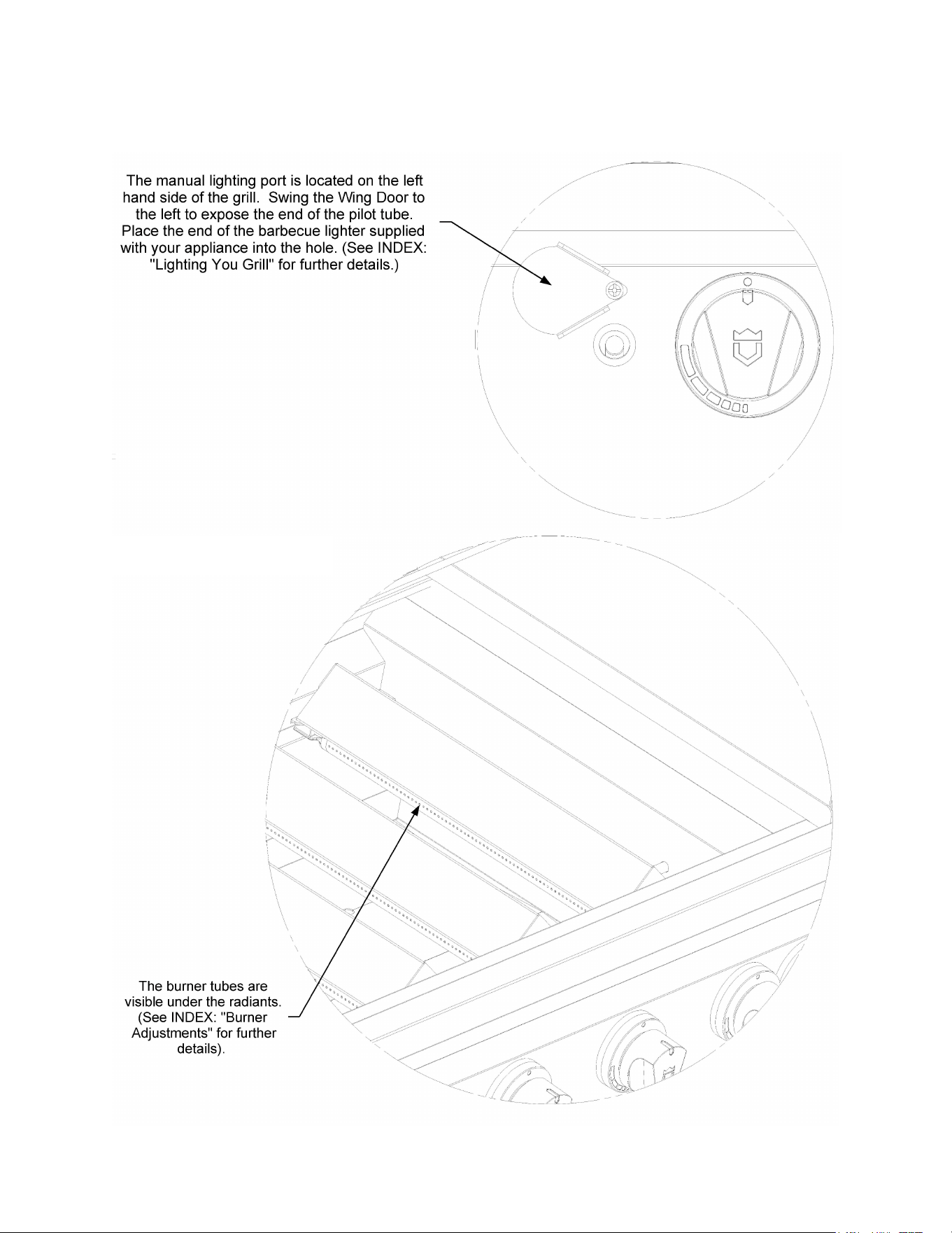
•
Insert a barbeque lighter into the hole located behind the wing door on the face of the grill
(See “Figure 13”).
•
Visually inspect to see that the pilot tube is lit.
•
Turn the main burner valves on to the desired temperature setting (See INDEX: “General
Operating Procedures” for guidelines on how to determine ideal temperature settings).
Ignition should take place within 2 to 3 seconds. Verify that the burners are lit by looking
through the grates on the cooking surface (See “Figure 14”). If the burners do not light
within this time, turn the temperature knob to the OFF position and wait 5 minutes for the
gas to dissipate before trying again. If the unit will not light after multiple attempts, refer to
the troubleshooting section of this manual.
A
C
D
Page 44 of 69
FIGURE 13. MANUAL LIGHTING
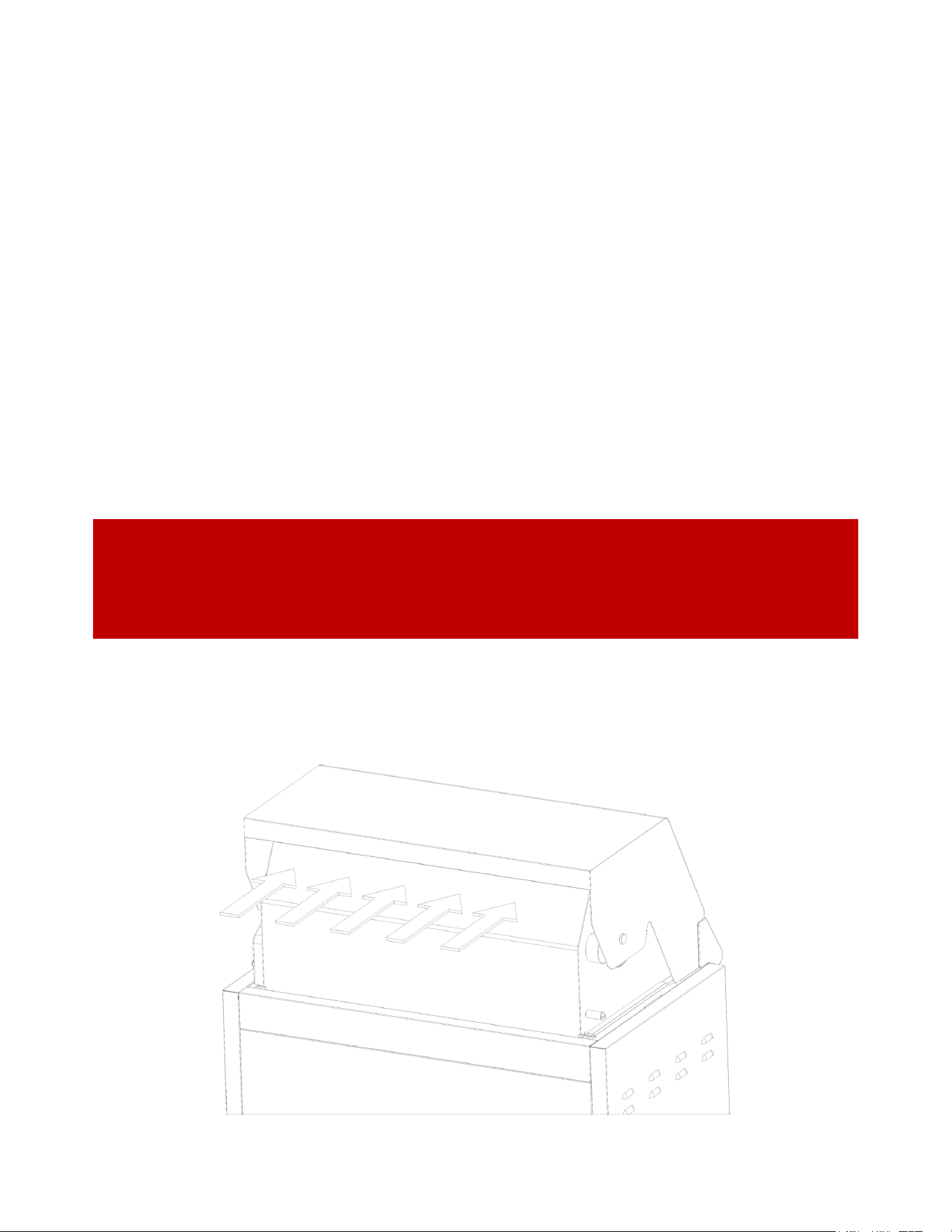
FIGURE 14. BURNER
Page 45 of 69
IMPORTANT: Any damage caused from use in windy conditions, such as melted
knobs or ignitor wires, or control panel discoloration from heat buildup, is
excluded from warranty
FIGURE 15. WIND DIRECTION
Prevailing winds blowing into the back of the dome can
cause damage to the grill.
Grilling in Windy Conditions
For outdoor grills to sear and grill steaks they have high performance burners that require
constant, steady supply of fresh air to mix with the fuel. Your Crown Verity grill pulls air in
through the front of the grill. Using your grill in windy conditions can disrupt the front to back
air flow (See “Figure 15”). If, while grilling with all burners on high and the lid closed, you notice
that the temperature gauge fails to rise, be cautious. If wind has kept hot gases from exiting the
rear of the grill the control panel and knobs may have become extremely hot.
To prevent the possibility of improper heat buildup caused by windy conditions:
• Do not leave the hood down when the burners are on high if the grill is unattended.
• If you suspect the grill is overheating, using an oven mitt, open the hood. Then adjust the
burner control knob to a lower setting.
• Install your grill with a wind break behind it.
• Orient the grill so prevailing winds are not blowing into the rear of the grill.

Page 46 of 69
Basic Grilling
PRE-HEATING
Preheating your grill every time you use it is important. Preheat your grill by igniting all main
burners and setting them to the highest setting. Then close the hood and allow the grill to heat
for 5 to 8 minutes. The hood thermometer should reach approximately 450 degrees. Once you
have reached your desired pre-heat temperature, turn off the burners that you will not be using
to cook your food. Please note, the surface temperature can be up to 200 degrees higher.
TYPES OF COOKING
Your Crown Verity grill has the capabilities of creating a range of heat intensities. By varying the
heat output, the number of burners used and the position of the hood, you can create either
direct or indirect heat or a combination of both. There are two basic types of grilling in an
outdoor grill, Direct Heat, or Indirect Heat.
Direct Heat: Direct Heat cooking occurs when foods are placed directly over the heat source.
This form of heat is known as radiant heat because the heat radiates directly from the source to
the food. Direct heat is necessary when you want to sear the outside of your food to lock in the
flavor.
Indirect Heat: Indirect Heat cooking occurs when the food is not close to the heat source. Heat
reaches the food from air movement within the cooking area. This form of heat is known as
convection heat. This type of cooking is achieved by placing the food on one side of the grill and
running the burners on the other side. You leave the burners below the food in the OFF
position. You should keep the hood closed as much as possible during this type of cooking to
maintain even heat distribution around the food. You regulate the heat by adjusting the burner,
using the hood thermometer to monitor the temperature.
WARNING: DO NOT LEAVE THE GRILL UNATTENDED
Do not leave the grill unattended during the pre-heat cycle or at any time while
in use. Pre-heating for more than 10-15 minutes may overheat the grill, causing
damage to the grill.

Page 47 of 69
Burner Adjustments
Every burner is tested and adjusted at the factory for proper performance. If a burner
is not operating properly, it may be due to variations in the local gas supply or because
of an obstructed air shutter or orifice. Flames should be stable without lifting from the
burner. The flames should burn cleanly without creating any sooty residue.
BURNER FLAME CHARACTERISTICS:
•
The flame should be mostly blue and stable with only a small amount of orange, if
any, at the tips. There should be little noise and no lifting. A muffled “pop” when
the burner is turned off is normal.
•
The inner cone should be 1/4 inch (6.4 mm) high.
•
The outer cone should be 5/8 inch (15.9 mm) high.
Visually inspect the flames in your grill and adjust if necessary, using the instructions
below.
IMPORTANT:
A sooty flame is usually caused by dirt, debris or spider nests blocking the
air shutter or orifice. This is a dangerous condition. The grill should NOT be used until
the problem is rectified. If you are not comfortable addressing the issue yourself,
please hire a licensed technician or contact Crown Verity Service at 1-888-505-7240.
TO CLEAN THE AIR SHUTTER:
Turn off the gas supply shutoff valve or close the main valve on the LP cylinder. Ensure
the grill control knobs are in the OFF position. Be sure that the unit is cool.
Next, remove the grates. They are heavy and care should be taken in removing them,
so they do not damage the outer surface of the appliance.
Next, remove the faceplate of the burner box by first removing all of the knobs and
then removing the screws holding the face in place (See “Figure 16”). Once the screws
are removed, gently lift the face up and forward to remove. If the grill is equipped
with a light package, disconnect the wire harness from the individual burner bezels as
well as the two switch connections. Place the face down on its back to avoid surface
scratches.
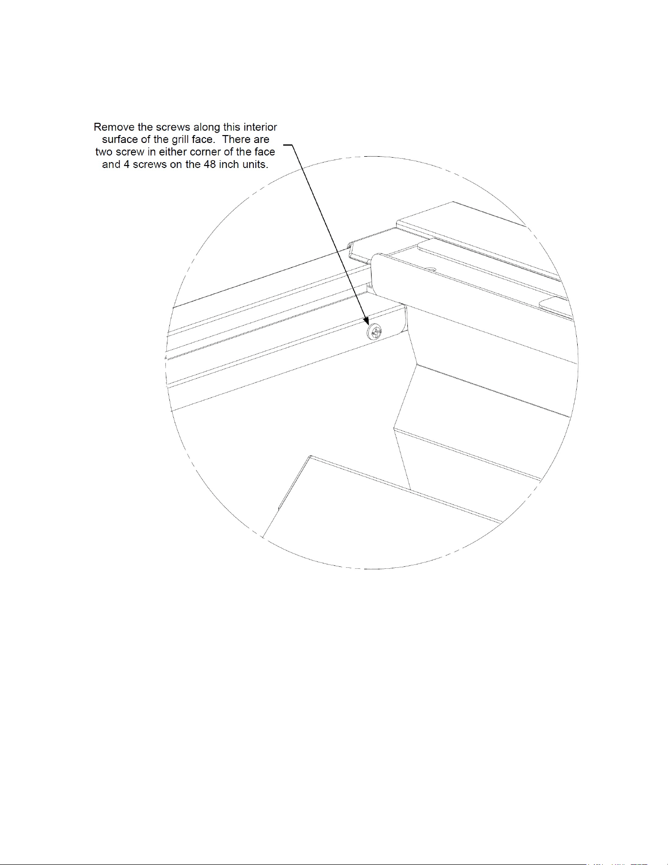
Page 48 of 69
The shutter is located at the end of the burner tubes closest to the gas orifice (See
“Figure 18” for further details).
Use a flashlight to view the screened openings of the air shutter from and remove any
obvious obstructions from the screen protecting the air shutter.
TO ADJUST THE AIR SHUTTER:
Leave the gas supply shutoff valve in the OFF position or leave the main valve on the LP
cylinder in the closed position. The grill control knobs should also remain in the OFF
position.
FIGURE 16. FACE REMOVAL
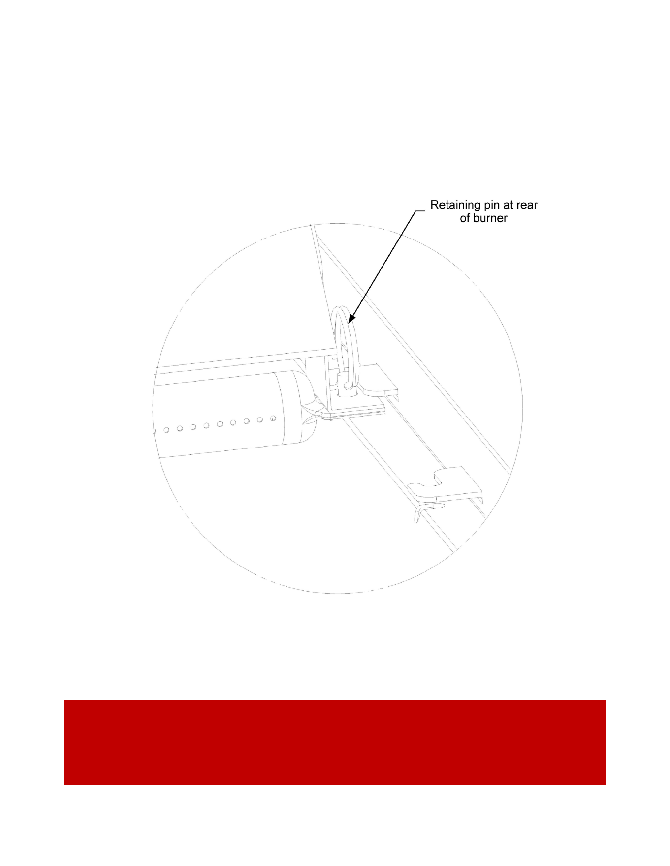
Page 49 of 69
With the roll dome open, remove the pins located at the far end of the burner
assemblies. Slide the burner gently to either the right or left to disengage them from
the retaining bracket. Once clear, lift the burner up and pull it back and away from the
back side of the gas valve (See “Figure 17” for further details).
Using a screwdriver, loosen the shutter adjustment lock screw (See “Figure 19”). Be
careful not to remove the lock screw. Once loose, you can rotate the air shutter to
adjust the amount of air entering the venturi. Replace the burners into the appliance
to adjust the air shutters.
IMPORTANT: Use caution when handling the burner tubes as they can get very
hot. The radiant surface can also get very hot and can cause severe burns. Use
caution when handling components and use protective gloves.
FIGURE 17. BURNER ASSEMBLY DETAILS
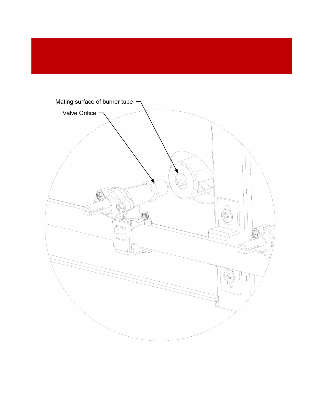
Page 50 of 69
Turn on the gas supply valve or open the main valve on the LP cylinder. Following the
lighting instructions (See INDEX:” Lighting Your Grill” for further details), light the burners
to be adjusted.
IMPORTANT: Always ensure that the brass orifices are inserted into the holes in
the ends of the air shutters and centered (See “Figure 18” for further details).
FIGURE 18. ORIFICE ACCESS AND ALIGNMENT
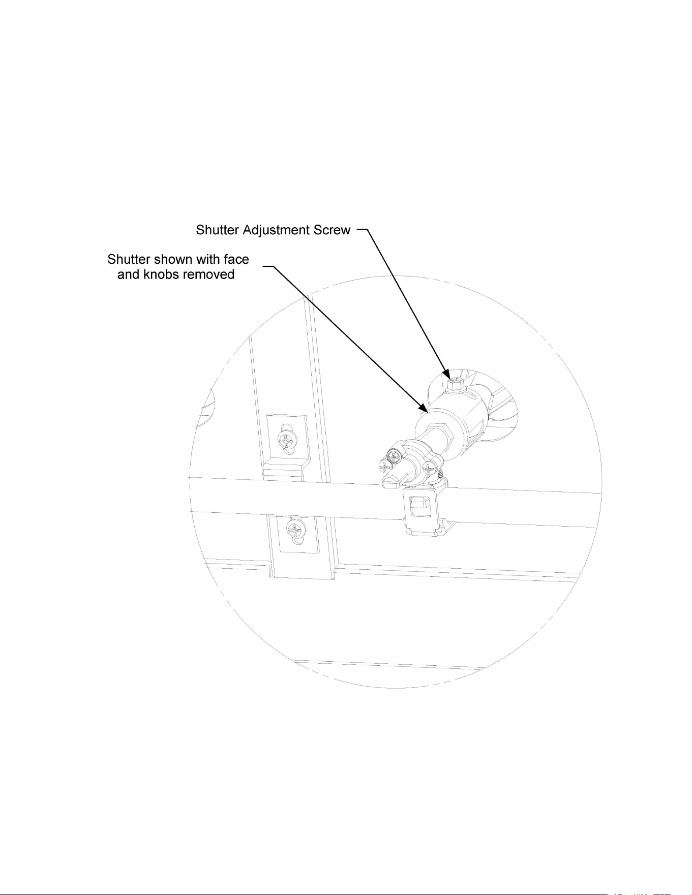
Page 51 of 69
If the flames are mostly yellow or are noisy and lift off the burner ports, rotate the air
shutter to progressively reduce the amount of air entering the venturi.
Continue to
close the air shutter until the flame no longer lifts from the burner. For a sooty flame,
progressively open the air shutter until the flame burns cleanly.
Once adjusted to a stable flame that burns cleanly and does not lift, turn the grill control
knob to the OFF position. Tighten the lock screw. Re-light and confirm the adjustment is
good. Once confirmed, replace the radiant and burner tube, place the pin back into hole at
the back of the burner tube to secure the radiant and burner tube in place, then replace
the faceplate. For appliances equipped with the lighting option, ensure that all
connections are made to the switches and bezels.
FIGURE 19. SHUTTER ADJUSTMENT

Page 52 of 69
Caring for Your Grill
STAINLESS STEEL CARE:
The Crown Verity Grills is built from 304 stainless steel, which is a high-quality, non-
magnetic stainless steel that is very corrosion resistant. It is also a highly sanitary
surface.
The stainless steel components of your grill are warranted for life against
structural deterioration or failure (See INDEX: “Commercial and Residential Warranty”
for further details). With proper care, your grill should last a lifetime. The stainless
steel will discolor from the intense heat over time; this condition is normal.
Always clean your stainless steel grill with a mild, food-safe, organic degreaser, followed
by a stainless steel polish.
ALWAYS SCRUB WITH THE GRAIN, NEVER ACROSS
.
Remove all
cleaner residue before lighting the grill in order avoid a build-up of film from the cleaner.
COOKING GRATE CARE:
Clean the cooking grates with a long-handled brass brush, or wooden paddle. It is best
to do this while the cooking grates are warm to hot.
•
Wear long, insulated gloves and use caution when doing so.
•
Never drop the cooking grates, as the welds along the rungs can crack.
SALT WATER ENVIRONMENTS: 304 Stainless steel is corrosion resistant but is not
impervious to rust in salt-water environments. Exposure to salt air and sea spray
will eventually damage the appliance if not cared for properly. The best thing
you can do to protect it is to clean it frequently. Don’t give the salt time to
establish the chemical reaction that contributes to rust. In salt air environments,
we recommend cleaning all stainless steel surfaces at least every two weeks to
keep your grill in prime condition. When not in use, we recommend that you
keep the cover on the appliance.
POOLS AND CHLORINE: chlorine in the air from pools can also damage 304
Stainless steel over time. Again, the best thing you can do to protect it is to
clean it frequently. We recommend cleaning all stainless steel surfaces at least
every two weeks to keep your grill in prime condition. When not in use, we
recommend that you keep the cover on the appliance.

Page 53 of 69
BURNER CARE:
The burners should be visually inspected once a year. To access the burners, first make
sure the grill is completely cooled. Ensure the control valves are in the OFF position
and turn off the main gas
supply. Open the roll dome or remove completely. Carefully
remove the cooking grates as they are heavy. The radiants and burners are now exposed.
Visually inspect the burners to confirm they are structurally sound. You have the option
of removing the radiant to gain better visual access if desired (See “Figure 17” for further
details).
It is unlikely the burners in your grill will become dirty. However, they may be cleaned
using a brass brush if necessary. Gently brush off any debris, being careful not to
dislodge the burners. Clogged burner ports may be opened up with a straightened
paper clip. Do not use a toothpick or anything else that could break off inside the
burner ports. To remove the burners for cleaning, remove the burner pin and swing
the radiant and burner to either side of the retaining bracket to lift and remove the
burner
(See “Figure 17” for further details).
After cleaning the burners, you must make
sure the venturi opening of the burner is centered over the brass orifice when
replacing the burner. Once the burners are in place, reassemble the grill and visually
inspect the gas hose before lighting.
ORIFICE CLEANING:
Clogged orifices create a dangerous condition that must be resolved before the grill
may be used. If you are not entirely comfortable with the procedure, please use a
licensed technician or contact Crown Verity customer service at 1-888-505-7240
The orifices can be accessed once the burners are removed. Remove the brass orifice
using a 1/2 inch ratcheting socket wrench (See “Figure 18” for further details).
Shine a flashlight through the orifice to look for any obstructions. Remove obstructions
with a needle. Use extreme care not to enlarge the hole. Reinstall and tighten the orifice.
Re-install the burner ensuring it is centered on the orifice. Test fire the burners and check
for proper flame characteristics.
IGNITER BATTERIES:
For appliances not equipped with a lighting package, t
he electronic ignition system is
battery operated. If you do not hear a rapid and strong clicking sound when you press
and hold the operating knob, you may need to change the batteries.

Page 54 of 69
EMPTYING THE GREASE/WATER TRAY:
The grease tray should be cleaned after every use. The tray is equipped with a drain cap that can be
removed to drain the water/ grease mixture from the tray.
WARNING:
The tray gets extremely hot when the grill is operating. Empty the tray only when
the grill is cool. Before using the grill is a good time to empty the tray.
Pull the tray forward so that the drain cap is clear of the front of the appliance. Place a bucket under
the cap and slowly remove the drain cap. The water gas mixture in a full tray will flow outward at first
so ensure the bucket is positioned to capture the contents. Once emptied, replace the drain cap and
remove the tray completely to wipe out any excess grease.
With the grease tray removed, next remove the grease deflector. Pull it out and wipe down any
grease that has deposited on the deflector. Once cleaned, place the grease deflector back in
place ensuring it is pushed all the way to the back of the fire box. Re-install the grease tray
ensuring the drain cap is tightened. Install the grease tray with approximately three inches of
the tray exposed and fill the tray with approximately one inch of water. Once filled, push the
tray into place ensuring that it is positioned all the way to the stop at the back of the fire box.
Troubleshooting
The troubleshooting tips here are for general information only. The information may
save you the trouble of a service call. If your grill requires service, contact Crown Verity
customer service at 1-888-505-7240.
GRILL WON’T LIGHT:
The grill/side burners are equipped with an electronic ignition system. To check if the system is
working try the following:
•
Do you hear a rapid clicking noise when you press and hold the electronic ignition button? If
there is no clicking, or the clicking is slow or faint, replace the ignition batteries (See INDEX:
“Caring for Your Grill” for further details).
•
For appliances equipped with a light package, if there is not a rapid clicking noise try turning
on the lights to ensure that the grill is connected to power.
•
If you do hear rapid clicking, but the grill won’t light with the electronic ignition, try
manually lighting the grill (See INDEX: “Lighting Your Grill” for further details). If the unit
does not light manually, there may not be any gas getting to the burners. Turn the grill
control knobs to the OFF position. Confirm that the grill is connected to the gas supply, that
the main gas supply is on, or that the LP cylinder is not empty.

Page 55 of 69
SMELL OF GAS WHILE COOKING:
IF YOU SMELL GAS WHILE THE GRILL IS OPERATING, IMMEDIATELY TURN OFF ALL
BURNERS AND SHUT OFF THE MAIN FUEL SUPPLY.
•
Perform a leak test (See INDEX: “Leal Test Procedure” for further details).
•
Check for blockages (See INDEX: “Caring for Your Grill” for further details).
GRILL WON’T GET TO TEMPERATURE:
If the unit does not get to operating temperature within 30 minutes of starting, the
burners may not be getting sufficient gas flow.
•
If possible, re-orient the oven to ensure that excessive wind is not affecting performance.
•
Leaving the burner valve open before opening the cylinder valve may cause the flow
control device to activate. Close all valves and follow the lighting procedures
(See
INDEX: “Lighting Your Grill” for further details).
.
•
LP cylinder does not have enough gas to deliver proper pressure. Change the tank if
necessary. In some situations, in cold ambient temperatures, an LP cylinder will ice up,
creating a drop in pressure. If this happens, turn off the tank and let it warm up before
trying again. A full tank is less likely to ice up than a tank that is less than half full.
•
Check that the Main gas supply is fully on and not partially opened.
•
Have the line pressure checked by a qualified technician (See INDEX: “Gas Connections” for
further details.)
•
Orifices are clear and not clogged. A clogged orifice creates a dangerous situation. Do
not use the grill until the issue has been resolved (
See INDEX: “Caring for Your Grill” for
further details).
THE GRILL IS PRODUCING A LOT OF SMOKE:
This is typically caused by something oily getting onto the cooking grates. If this
happens, the only thing you can do is to try and burn it off. Use caution when doing
this as the grill will get extremely hot very fast, so never leave it unattended when
trying to burn off any oily substances. Burnt cheese or other solids can be scraped or
brushed off the cooking grates.
THE LIGHTS WON’T ILLUMINATE:
If the grill/side burner were purchased with an optional light package and the lights won’t
illuminate, try the following:

Page 56 of 69
•
Ensure that the appliance is connected to a live AC power source.
•
Check the 12 volt harness connection to the power supply.
•
If the switches are not illuminated, remove the face, and check the switch
connections
(See INDEX: “Burner Adjustments” Figure 16, for further details).
•
If the switches are illuminated but the burner knobs are not, remove the face and
check the harness connections to the LED bezels
(See INDEX: “Burner Adjustments”
Figure 16, for further details).
•
For dome lights, replace the bulb. The replacement bulbs are halogen, 12 volt,
10W, T3 Type with a G4 bi-pin. They are readily available at most home
improvement stores. Avoid touching the glass on the new bulb as it may shorten
their life. Pull the old bulb out without twisting and replace holding the new bulb
with a paper towel or cloth to hold the bulb.
Contacting Crown Verity Customer Care
Before calling Crown Verity Customer Care, please make sure you have the following
information:
• Model Number
• Date of purchase
• Proof of purchase by original owner
• Serial number
For warranty service, contact Crown Verity Service Department for an authorized service agent
near you at: (888) 505-7240 or servi[email protected]ty.com
Contact Crown Verity for replacement parts. Parts are shipped F.O.B Brantford, ON or
Bowling Green, KY.

Page 57 of 69
Installation Checklist
Installer should initial next to each item:
Specified clearances maintained.
Initial assembly completed — all tape and internal packaging removed.
Grease/water tray installed.
Burner knobs installed.
Cooking grates installed.
Igniter starts pilot tubes when button is depressed.
For appliance equipped with a light package, the lights turn on.
Pilot and Burner Tubes light.
Gas pressures have been set in accordance with the rating plate on the grill.
Manual shutoff valve is installed and accessible.
Owner informed of shutoff valve location.
Unit and supply connections have been tested and are free of leaks.
Leave this Manual with the owner.
Installer Signature Date
Please ensure the installer completes the checklist,
explaining each item to you. The
installer should initial each item above
and sign below.

Page 58 of 69
Commercial & Residential Warranty
RESIDENTIAL LIMITED WARRANTY TERMS & CONDITIONS
This warranty is limited to products manufactured by Crown Verity Inc., to the original
purchaser, commencing on the date of purchase and is valid only with a proof of purchase. This
warranty page and its coverage only applies to Infinite SeriesTM, Estate SeriesTM and PRO
SeriesTM grills. The warranty covers defects in material and workmanship under normal use,
providing that:
1. The equipment is properly installed per Crown Verity’s Operator’s Manual and by a
qualified professional installer, including all start-up checks.
2. The equipment has not been accidently or intentionally damaged, altered, or misused.
3. The serial number rating plate affixed to the equipment has not been intentionally
defaced or removed.
4. The equipment is used in a residential application as defined by ANSI Z21.58/ CSA 1.6
current versions.
To activate the Crown Verity warranty please visit our warranty registration page
https://crownveritycanada.ca/support#faqs This warranty is limited to the original purchaser and
cannot be transferred.
WARRANTY COVERAGE
LIMITED WARRANTY
Crown Verity will warrant replacement parts for Canada and the Continental United States for
the following period:
Limited Lifetime Warranty: The stainless-steel grill body, stainless steel gas burners and
cooking grates are warranted to be free from defects in material and workmanship when
subjected to normal domestic use and maintenance for the lifetime of the original purchaser.
This warranty excludes surface corrosion, scratches, and discoloration which may occur during
normal use. Failure to perform required maintenance will void this warranty.

Page 59 of 69
Limited Six-Year Warranty: The Radiants, Manifolds and Gas valves are warranted to be free
from defects in material and workmanship when subjected to normal domestic use and
maintenance for six (6) years from the original date of purchase. Failure to perform required
maintenance will void this warranty.
Limited One-Year Warranty: For a period of one (1) year from the original date of purchase,
Crown Verity will replace, or repair parts found to be defective at no cost to the original
purchaser. This includes the cost of shipping replacement parts and, where necessary, service
labor at prevailing local rates by a Crown Verity authorized service person. Service will be
provided during normal business hours and must be authorized in advance by Crown Verity.
All non-grill components, such as modular and built-in cabinetry, fall under the Limited One Year
Warranty.
WARRANTY LIMITATIONS
The Crown Verity warranty does not apply to damages caused by:
• Negligence.
• Installation or start-up, damages or problems caused by improper installation or use.
• Unauthorized repair by anyone other than a Factory Authorized Service Agent.
• Erratic voltages or gas supply.
• Air and Gas adjustment.
• Damage caused by nature.
• Ordinary wear and tear.
• Display models are sold “as is”. If you have purchased a display model, please be
advised that it is sold “as is” and that it is subject to the following warranty exclusions:
any exterior or cosmetic damage is non-warrantable; any missing components will be
replaced at consumer’s expense; major handling damage to manifold, valve and ignition
system will be serviced at consumer’s expense; all other warranties will remain in effect.
• The equipment is properly installed per Crown Verity’s Operator’s Manual and by a
qualified professional installer, including all start-up checks.
• The cost of a service call to diagnose complaint.
• Modification to Crown Verity product will void related warranties.

Page 60 of 69
WARRANTY EXCLUSIONS
The Crown Verity warranty does not apply to labor or repairs required for:
• Batteries, fuses, and other wearable items
• Door adjustments and or lid adjustments
• Tightening of screws or fasteners
• Damage in shipment
• Adjustments and cleaning of main burners pilot burners or orifices
• Accessories such as brushes, spatulas, and cylinders
• Normal discoloration of materials
• Units used in a commercial application. Refer to our Commercial Warranty.
COMMERCIAL LIMITED WARRANTY TERMS & CONDITIONS
This warranty is limited to products manufactured by Crown Verity Inc., to the original
purchaser, commencing on the date of purchase and is valid only with a proof of purchase. The
warranty covers defects in material and workmanship under normal use, providing that:
1. The equipment is properly installed per Crown Verity’s Operator’s Manual and by a
qualified professional installer, including all start-up checks.
2. The equipment has not been accidently or intentionally damaged, altered, or misused.
3. The serial number rating plate affixed to the equipment has not been intentionally
defaced or removed.
4. The equipment is used in a commercial application as defined by ANSI Z83.11/CSA 1.8.
To activate the Crown Verity warranty please visit our warranty registration page
https://crownverity.ca/ support#faqs. This warranty is limited to the original purchaser and
cannot be transferred.
WARRANTY COVERAGE
LIMITED WARRANTY
Crown Verity will warrant replacement parts for Canada and the Continental United States for
the following period:
Limited Lifetime* Warranty: The stainless-steel grill body and cooking grates are warranted to
be free from defects in material and workmanship when subjected to normal domestic use and
maintenance for the lifetime of the original purchaser. This warranty excludes surface

Page 61 of 69
corrosion, scratches, and discoloration which may occur during normal use. Failure to perform
required maintenance will void this warranty.
* Applies to all grills sold after January 1, 2015 or with a serial number higher than 21010.
Limited Ten-Year Warranty: The stainless steel gas burners are warranted to be free from
defects in material and workmanship when subjected to normal domestic use and maintenance
for ten (10) years from the original date of purchase. Failure to perform required maintenance
will void this warranty.
Limited One-Year Warranty: For a period of one (1) year from the original date of purchase,
Crown Verity will replace, or repair parts found to be defective at no cost to the original
purchaser. This includes the cost of shipping replacement parts and, where necessary, service
labor at prevailing local rates by a Crown Verity authorized service person. Service will be
provided during normal business hours and must be authorized in advance by Crown Verity.
The limited one-year warranty covers Crown Verity Grills, Griddles, Fryers, Steamers, Sinks &
Pizza Ovens.
WARRANTY LIMITATIONS
The Crown Verity warranty does not apply to damages caused by:
• Negligence.
• Installation or start-up, damages or problems caused by improper installation or use.
• Unauthorized repair by anyone other than a Factory Authorized Service Agent.
• Erratic voltages or gas supply.
• Air and Gas adjustment.
• Damage caused by nature.
• Ordinary wear and tear.
• Display models are sold “as is”. If you have purchased a display model, please be
advised that it is sold “as is” and that it is subject to the following warranty exclusions:
any exterior or cosmetic damage is non-warrantable; any missing components will be
replaced at consumer’s expense; major handling damage to manifold, valve and ignition
system will be serviced at consumer’s expense; all other warranties will remain in effect.
• The equipment is properly installed per Crown Verity’s Operator’s Manual and by a
qualified professional installer, including all start-up checks.
• The cost of a service call to diagnose complaint.
• Modification to Crown Verity product will void related warranties.

Page 62 of 69
WARRANTY EXCLUSIONS
The Crown Verity warranty does not apply to labor or repairs required for:
• Batteries, fuses, and other wearable items
• Door adjustments and or lid adjustments
• Tightening of screws or fasteners
• Damage in shipment
• Adjustments and cleaning of main burners pilot burners or orifices
• Accessories such as brushes, spatulas, and cylinders
• Normal discoloration of materials
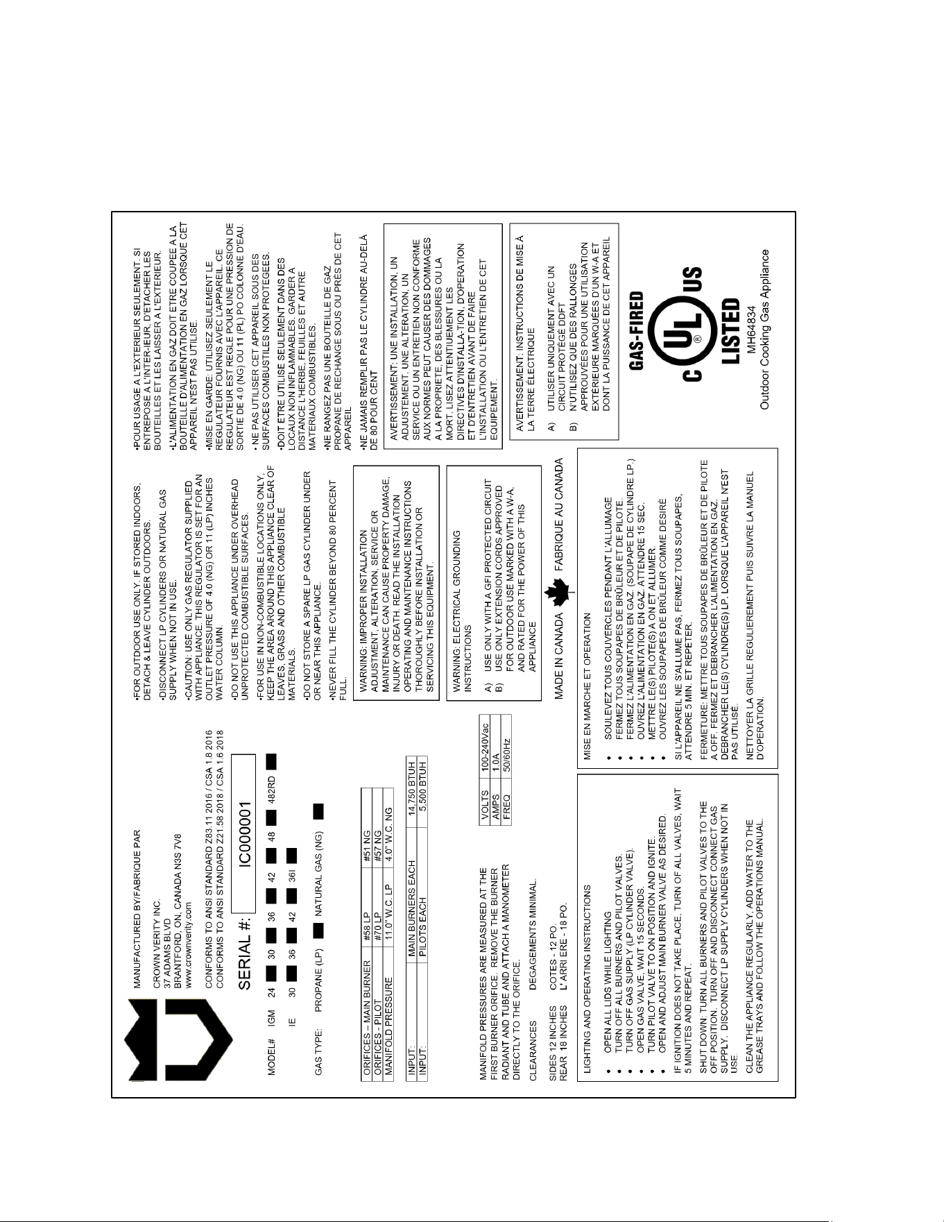
Page 63 of 69
Appendix “A”
GRILL RATING PLATE
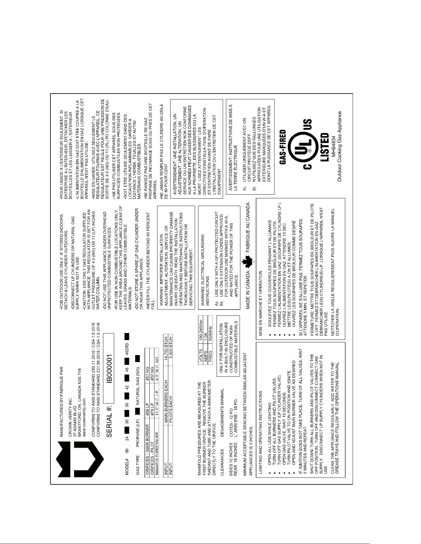
Page 64 of 69
Appendix “A” Cont’d
BUILT-IN RATING PLATE
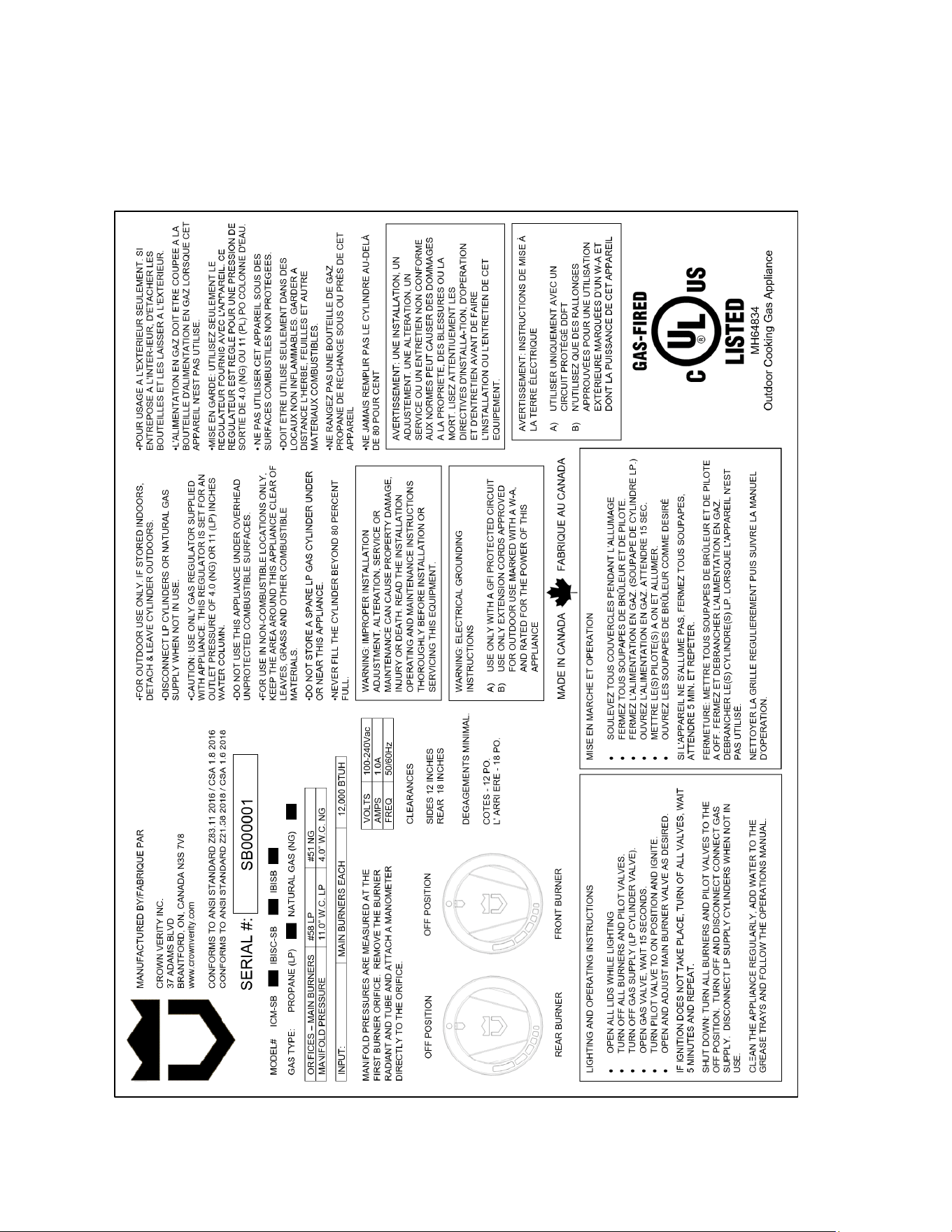
Page 65 of 69
Appendix “A” Cont’d
SIDE BURNER RATING PLATE
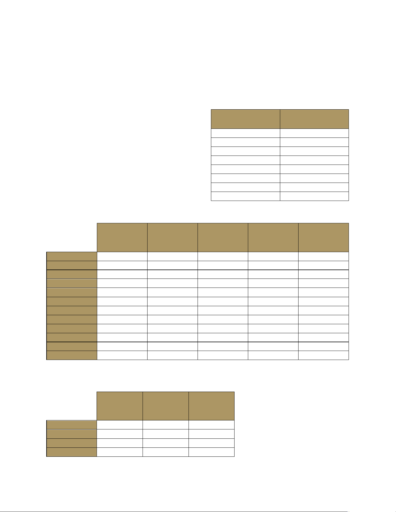
Page 66 of 69
Appendix “B”
PRESSURE DROP TABLE (See INDEX: “Gas Connections” for further details).
The BTU’s for each appliance are listed in the
tables below for reference. Find the maximum
BTU requirements for the appliance(s) purchased
adding the combined BTU’s together. Cross
reference the total BTU’s against “Table 3” to
determine the maximum allowable supply line
length for the BTU’s required. If the supply line
length available does not support the BTU
requirements, the pipe size will need to be
changed accordingly. Please contact a certified
gas technician for additional size options.
BTU Grills: Table 1
BTU’s
LP Pilot
Orifice - 70
BTU’s
LP Burner
Orifice - 58
BTU’s
NG Pilot
Orifice - 57
BTU’s
NG Burner
Orifice - 51
Total BTU’s
NG/LP
IBI30
5,500
14,750
5,500
14,750
64,500
IBI36
5,500
14,750
5,500
14,750
79,250
IBI42
5,500
14,750
5,500
14,750
94,000
IBI48
5,500
14,750
5,500
14,750
108,750
IBI482RD
5,500
14,750
5,500
14,750
94,000
IGM24
5,500
14,750
5,500
14,750
49,750
IGM36
5,500
14,750
5,500
14,750
79.250
IGM42
5,500
14,750
5,500
14,750
94,000
IE30
5,500
14,750
5,500
14,750
64,500
IE36
5,500
14,750
5,500
14,750
79,250
IE42
5,500
14,750
5,500
14,750
94,000
IE36I (GRILL)
5,500
14,750
5,500
14,750
79,250
BTU Side Burners: Table 2
BTU’s
LP Burner
Orifice - 58
BTU’s
NG Burner
Orifice - 52
Total BTU’s
NG/LP
IBISB
12,000
12,000
24,000
IBISC-SB
12,000
12,000
24,000
ICM-SB
12,000
12,000
24,000
IE36I (SB)
12,000
12,000
24,000
Maximum Runs for All Appliances
on a supply Line: Table 3
Run Length
3/4 Pipe (in feet)
Max BTU for All
Appliances on Line
10
360,000
20
245,000
30
198,000
40
169,000
50
150,000
60
135,000
70
123,000
80
115,000
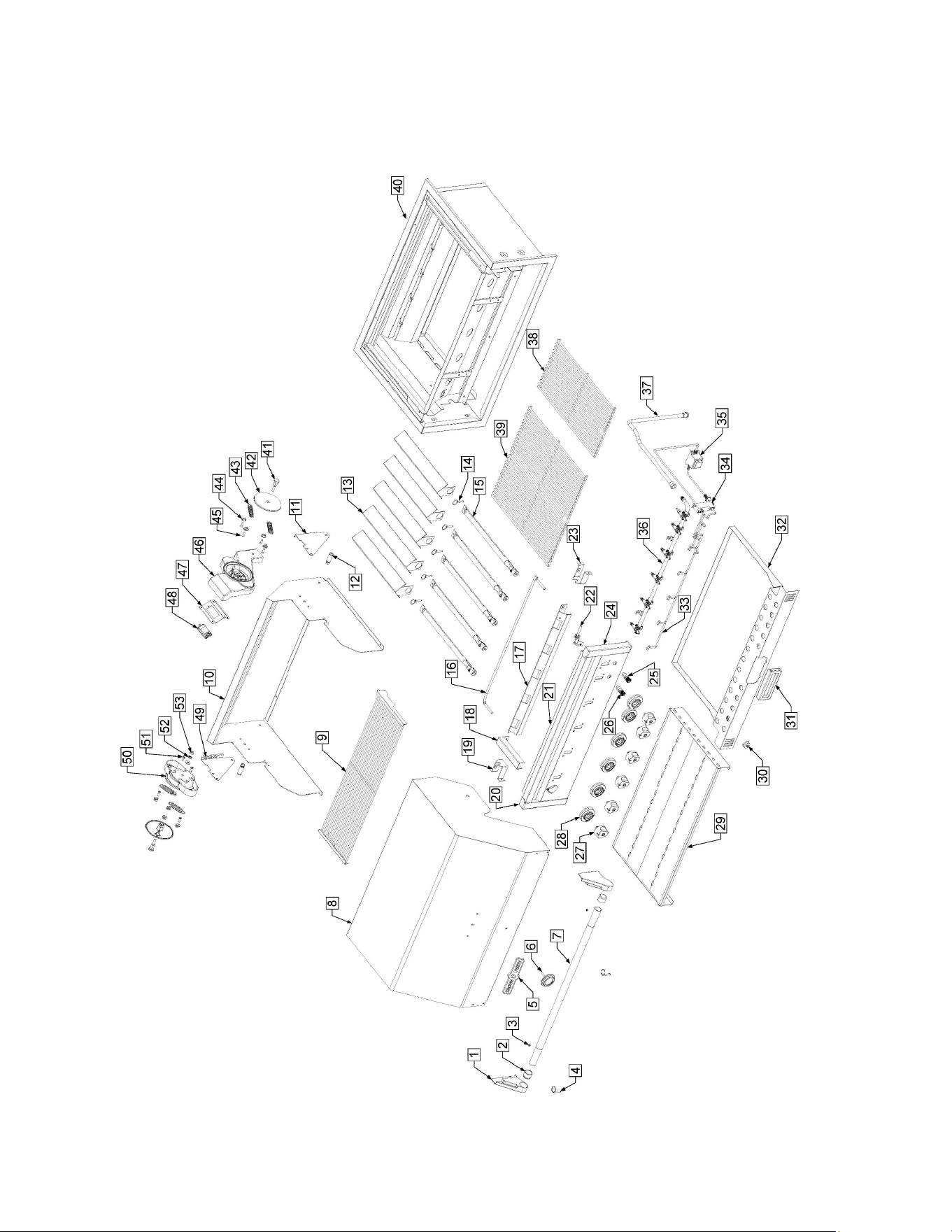
Page 67 of 69
Exploded Parts View

Page 68 of 69
Grill Parts List
ITEM
DESCRIPTION
PART NUMBER
1
HANDLE END CAP
ZCV-EMC-RD-1014
2
HANDLE INSERT
ZCV-EMC-RD-1000
3
DOME GROMMET
ZCV-MS35489-1X
4
DOME RETAINER PIN
ZCV-2020
5
DOME NAME PLATE
ZCV-2003-16
6
DOME THERMOMETER
ZCV-2005
7
DOME HANDLE
ZCV-EMC-RD36-3-1002
8
OUTER DOME ASSEMBLY
ZCV-EMC-RD36-5-1000
9
BUN RACK
CV-ABR-36/72
10
INNER DOME ASSEMBLY
ZCV-EMC-RD36-6-1000
11
RH BUN RACK BRACKET
ZCV-EMC-RD-1009
12
DOME STOP HARDWARE
ZCV-4040
13
RADIANT
ZCV-2070
14
BURNER PIN
ZCV-2020
15
TUBE BURNER
ZCV-2060
16
PILOT TUBE
ZCV-3032-BI
17
PILOT TUBE COVER
ZCV-EMC-GB36-2
18
LIGHTER TUBE COVER
ZCV-EMC-GB-6
19
PILOT TUBE COVER BRACKET LH
ZCV-EMC-GB-7
20
FACE END CAP LH
ZCV-EMC-GB-1003-1
21
GRILL FACE
ZCV-EMC-36-3-1000
22
ELECTRODE ASSEMBLY
ZCV-2139
23
PILOT TUBE COVER BRACKET RH
ZCV-EMC-GB-5
24
FACE END CAP RH
ZCV-EMC-GB-1002-1
25
LIGHT SWITCH
ZCV-4036
26
IGNITION SWITCH
ZCV-4035
27
BURNER KNOB
ZCV-2094
28
BURNER BEZEL
ZCV-2094-2
29
DEFLECTOR PLATE ASSEMBLY
ZCV-IBI36-6-1
30
GREASE TRAY END CAP
F4-3025 Cap
31
INFINITE HANDLE ASSEMBLY
ZCV-EMC-DH2
32
GREASE TRAY ASSEMBLY
ZCV-IBI-36-6-2
33
LIGHT HARNESS ASSEMBLY
ZCV-4027-KFD
34
SPARK CONTROLLER
ZCV-4031
35
POWER SUPPLY
ZCV-4034
36
GRILL MANIFOLD ASSEMBLY
ZCV-CM-36-R-C
37
MANIFOLD HOSE ASSEMBLY
ZCV-4006
38
12 INCH GRATE
ZCV-2170
39
22 INCH GRATE
ZCV-2150
40
GRILL BODY ASSEMBLY
ZCV-EMC-GB36
41
PIVOT BOLT
ZCV-EMC-RDSA-3
42
SPRING ASSIST COVER
ZCV-EMC-RDSA-2
43
TENSION SPRING
ZCV-EMC-RDSA-5

Page 69 of 69
44
SPRING RETAINER
ZCV-EMC-RDSA-6
45
.250-20 COUNTERSUNK SCREW
ZCV-8084
46
DOME LIGHT HOUSING
ZCV-EMC-RDSA-8
47
DOME LIGHT COVER
ZCV-EMC-RDSA-7
48
DOME LIGHT
ZCV-EMC-RDSA-9
49
LH BUN RACK BRACKET
ZCV-EMC-RD-1010
50
SPRING ASSIST HOUSING
ZCV-EMC-RDSA-1
51
.250-20 PAN HEAD SCREW
ZCV-2196
52
.375 LOCK WASHER
ZCV-2010
53
.375-16 LOCKING NUT
ZCV-8081