Windows 10 / 8.1 / 7
SAFETY INSTRUCTIONS & INSTALLATION MANUAL
MANUAL DE INSTALACIÓN E INSTRUCCIONES DE
SEGURIDAD
안전 지침
- CPM-100G5/CPM-100HG5 -
- CPM-100HG5K -
The Manual provides the following information. El Manual brinda la siguiente información.
Be sure to read it before installing Asegúrese de leerlo antes de la instalación
into your personal computer. en su computadora personal.
Precautions for using the CPM-100G5/CPM-100HG5 Precauciones para el uso de CPM-100G5/CPM-100HG5
How to install and uninstall BepopPC EX software Cómo instalar y desinstalar el software
BepopPC EX
How to install and uninstall the printer driver Cómo instalar y desinstalar el controlador de la impresora
How to set the IP Address of the CPM-100HG5 Cómo establecer la dirección IP de CPM-100HG5
Basic operation of BepopPC EX software Funcionamiento básico del software BepopPC EX
N188N
The manual corresponds to BepopPC EX
CD-ROM.
Note that other Bepop PC/Bepop PC EX CD-ROM
versions may require completely different
operating systems and operating methods.
The CD-ROM is compatible with Windows 10 / 8.1 / 7 .
Keep this manual together with
CPM-100G5/CPM-100HG5.
It is prohibited to reproduce part or all of the manual
without our permission.
The information in the Manual is subject to change
without prior notice.
El manual corresponde a BepopPC EX CD-ROM.
Tenga en cuenta que las otras versiones de Bepop
PC/Bepop PC EX CD-ROM pueden requerir sistemas
operativos y métodos de operación completamente
diferentes.
El CD-ROM es compatible con Windows 10 / 8.1 / 7.
Guarde este manual junto con
CPM-100G5/CPM-100HG5.
Está prohibido reproducir parte o todo el manual sin
nuestra autorización.
La información en el Manual está sujeta a cambios sin
previo aviso.
without prior notice.


1
CONTENTS For details of BepopPC EX, see PDF Manual.
[Preparing the CPM-100G5/CPM-100HG5] ................................................ 2
Be Sure to Read ........................................................................................ 2
Precautions for Use ................................................................................. 3
1 Confirming the Package Contents ...................................................... 9
2 Component Units and Their Functions ............................................... 9
3 Working with the Tape roll ................................................................ 10
4 Working with the Ink Ribbon Cassette ............................................. 11
5 Working with the Cutting Tool .......................................................... 12
[Installing the BepopPC EX Software] .................................................. 27
Notes ....................................................................................................... 27
6
What is Possible with BepopPC EX ................................................... 28
7
Important: Read before Installation ................................................. 29
7.1 Environment of PCs Capable of Running with This Software .............................................................. 29
7.2 Precautions for Installation ..................................................................................................................... 29
7.3 Restrictions and Other Precautions ....................................................................................................... 29
8
Installation and Uninstallation .......................................................... 30
8.1 Setup Menu ............................................................................................................................................... 30
8.2 Installing BepopPC EX Software ............................................................................................................. 31
8.3 Uninstalling BepopPC EX ........................................................................................................................ 36
8.4 Installing only the Printer Driver ............................................................................................................. 37
8.5 Uninstalling the Printer Driver ................................................................................................................. 38
9
Setting the IP Address of the CPM-100HG5 ..................................... 39
9.1 Restrictions for LAN Connection ............................................................................................................ 39
9.2 Setting the IP Address of the CPM-100HG5 ........................................................................................... 40
10
Usage of BepopPC EX (1): Input and Output of Characters ............................ 42
10.1 Inputting the Characters .......................................................................................................................... 42
10.2 Outputting to Bepop ................................................................................................................................. 43
10.3 Checking the Remaining Tape roll Length ............................................................................................. 43
11
Usage of BepopPC EX (2): Import of Logo or Mark .......................... 44
11.1 Reading the Logo or Mark from the Scanner ......................................................................................... 44
11.2 Calling the Saved Symbol (When Using for BepopPC EX) ................................................................... 46
12
Troubleshooting ................................................................................ 47
Trademarks used in this manual
* Windows is a registered trademark of Microsoft Corporation.
2
For the customers in the USA
[Preparing the CPM-100G5/CPM-100HG5]
Be Sure to Read
Indications
The Manual and product use various indications to ensure that you can use the machine safely and correctly. The following
describes the indications:
WARNING
NEGLIGENCE OF THIS COULD LEAD TO A DEATH OR SERIOUS INJURY OF A
WORKER.
CAUTION
NEGLIGENCE OF THIS COULD LEAD TO AN INJURY OF A WORKER, DAMAGE YOUR
PROPERTIES ONLY, OR CAUSE CREATED DATA TO BE LOST.
Symbols
Denotes “what you should be aware of.” A specific caution is given in or close to this symbol.
Denotes “what you must not do.” A specific prohibition is given in or close to this symbol.
Denotes “what you must do.” A specific instruction is given in this symbol.
3
[Precautions for Use]
WARNING
Never disassemble or remodel the machine – it could result in a fire, electric shock, or trouble.
Do not insert any foreign object into the machine, such as a finger, pen, wire, etc., – it could result in a fire, electric shock, or
injury.
Use the supplied power cord.
Not using it could result in a fire or electric shock.
Obtain power directly from an AC120V 60Hz electrical outlet. Do not put multiple loads on the electrical outlet – it could cause a
fire.
Do not modify the power cord.
Never place a heavy object on a power cord – it may damage the cord, resulting in a fire or electric shock.
Do not use a bundled power cord.
The emitted heat may cause a fire or malfunction. Be sure to unbundle the power cord before use.
Do not connect or disconnect a power plug with a wet hand – You could receive an electric shock.
Do not operate the machine with wet hands or wet clothes.
You could receive an electrical shock.
Do not place paper or cloth on the machine when it is connected to an outlet.
Doing so could cause a fire or malfunction.
When disconnecting the power plug, hold it directly; never pull on the power cord.
Pulling on the cord can damage it, resulting in a fire or electrical shock.
Ensure that no water or chemicals are splashed over the machines. If water, etc., gets inside for some reason, disconnect the
power plug immediately from the electrical outlet, and contact your dealer for repair. If the machine is used in such a state, it
could malfunction or result in a fire or electric shock.
Never put a hand or an object into a cutter section – it can both cause machine trouble and personal injury.
Run the machine only on the indicated supply voltage – use of any other voltage could result in a fire or trouble.
Be sure to ground the machine.
Otherwise, if a short circuit occurs, a fire or electric shock may result.
Clean the power plug periodically.
Dust accumulated over a long period could cause a fire or trouble.
Keep a cutting tool (blade) out of the reach of children. If swallowed, seek immediate medical attention.
Do not use the machine if it has a symptom of a problem, such as smoke, abnormal sound, or foul odor – such use could result
in a fire or electric shock. In such a case, immediately disconnect the power plug from the electrical outlet, and contact your
dealer for repair.
CAUTION
Do not share an electrical outlet with any device (air conditioner, refrigerator, microwave, office automation equipment, etc.) that
requires a large capacity – it could lower the supply voltage and cause the machine to malfunction.
Install the machine on a flat surface. Do not install in an unstable location, such as on a wobbly platform or an inclined surface.
The machine could fall over or fall from the platform and cause injury or malfunction.
Do not use the machine under direct sunlight, in a hot, humid location, or when there is condensation.
It may cause unstable operation or a malfunction.
Do not place paper or cloth on the machine – it could result in a fire or trouble.
Never touch the thermal head. Immediately after printing, it is very hot and could burn you. Also, if the thermal head is thumbed,
it may cause trouble.
Clean the power plug periodically – dust accumulated over a long period could cause a fire or trouble.
When disconnecting the power plug, hold it directly – never pull on the power cord. Pulling on the cord can damage it, resulting in
a fire or electric shock.
When printing or cutting does not function properly due to jamming of an adhesive tape roll, ink ribbon, or foreign object inside
the machine, be sure to turn off the power before eliminating jamming – Otherwise, you could be injured by abrupt activation of
the machine could cause an injury.
When opening or closing a door cover, be careful not to get a hand, etc., caught.
When moving the machine, be sure to disconnect the power plug from the electrical outlet, close the door cover and hold the
4
sides of the body to carry it – neglecting this may damage the plug or cord and cause a fire or electrical shock, as well as this
could cause an injury or trouble.
When replacing the cutting tool (blade) or mounting/dismounting a tape roll, be sure to turn off the power. Otherwise, you could
be injured by abrupt activation of the machine.
Note that the cutting edge of the replacement blade is very sharp. Do not touch the tip of the cutting tool (blade) – you may be
injured.
When not using the machine for a long time, such as consecutive holidays, be sure to disconnect the power plug from the
electrical outlet, for safety.
Data saved in a personal computer cannot be saved permanently. We cannot be responsible for damage due to loss of data
attributable to trouble or repair, or lost profit.
Do not directly touch the connector with hand. Static electricity may cause trouble.
Disclaimers
MAX will not be held responsible for any damages that occur as a result of not following the
instructions in this manual, damages and lost profits resulting from not being able to use the
machine (malfunction), or any relevant secondary damages.
PRODUCT SPECIFICATIONS
Product
CPM-100G5
CPM-100HG5
Printer section
Printing method
Thermal transfer
Printing density
203dpi
400dpi
Printing speed
25 mm/sec. (1”/sec.)
Cutter section
Resolution
0.025 mm/step (0.001”/step)
Cutting speed
120 mm/sec. (4.7”/sec.) at maximum
Maximum output range
100 mm (3.9”) x 2000 mm (78.7”)
Interface
USB2.0 full speed
USB2.0 full speed
LAN 10baseT/100baseTX
Working environment
Temperature: 10-35C (50-95°F),
Humidity: 35-80 % (No dew condensation allowed)
Power source
AC 100 - 240 V 50/60 Hz 1A
Power consumption
85 W
Outer dimensions
330 mm (13.0”) x 320 mm (12.6”) x 320 mm (12.6”)
(W) x (D) x (H)
Mass (Main body only)
9 kg (19.8lbs.)
*Design, specifications, and the like are subject to change without notice.
5
FCC Notice
(Class A: CPM-100G5/CPM-100HG5)
NOTE: This equipment has been tested and found to comply with the limits for a Class A digital device, pursuant to part
15 of the FCC Rules. These limits are designed to provide reasonable protection against harmful interference when the
equipment is operated in a commercial environment. This equipment generates, uses, and can radiate radio frequency
energy and, if not installed and used in accordance with the instruction manual, may cause harmful interference to radio
communications. Operation of this equipment in a residential area is likely to cause harmful interference in which case
the user will be required to correct the interference at his own expense.
This device complies with part 15 of the FCC Rules. Operation is subject to the following two conditions:
(1) This device may not cause harmful interference, and
(2) this device must accept any interference received, including interference that may cause undesired operation.
Changes or modifications not expressly approved by the party responsible for compliance could void the user’s authority
to operate the equipment.
MAX USA CORP.
ADDRESS : 257 East 2nd Street Mineola, NY 11501, U.S.A.
PHONE : (516)741-3151 FAX : (516)741-3272
Notice
(CPM-100G5/CPM-100HG5)
This device complies with Industry Canada’s licence-exempt RSSs. Operation is subject to the following two conditions:
(1) this device may not cause interference; and
(2) this device must accept any interference, including interference that may cause undesired operation of the device.
Le présent appareil est conforme aux CNR d'Industrie Canada applicables aux appareils radio exempts de licence.
L'exploitation est autorisée aux deux conditions suivantes:
(1) l'appareil ne doit pas produire de brouillage;
(2) l'utilisateur de l'appareil doit accepter tout brouillage radioélectrique subi, même si le brouillage est susceptible d'en
compromettre le fonctionnement.
MAX USA CORP.
ADDRESS : 257 East 2nd Street Mineola, NY 11501, U.S.A.
PHONE : (516)741-3151 FAX : (516)741-3272
6

7
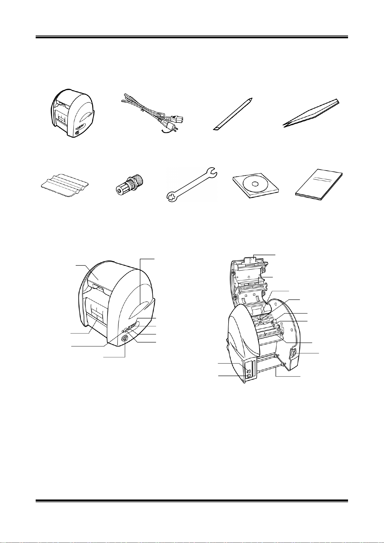
1. Confirming the Package Contents
Open the package and confirm that all of the following items are included.
<1> CPM-100G5/CPM-100HG5
<2> AC cable
<3> Blade (1 pc.)
<4> Tweezers
<5> Squeegee
<6> Tool Holder
(Attached upon
shipment)
<7> Tool holder
replacing spanner
<8> Application
Software CD
<9> Installation Manual
(this manual)
2. Component Units and Their Functions
[Front of Main Body] [Back of Main Body]
[Main Key Functions]
Power key : Used to turn on/off the power.
Tape roll feed keys : Used to feed the tape roll.
LED lamp : Illuminated in green when the Power switch is turned on. It is illuminated or blinks in red
when informing you of an error.
Door Cover
Vinyl Outlet
LED Lamp
Cutting Pressure Control Dial
Power Key
Vinyl Feed Key (Forward)
Vinyl Feed Key (Back)
Scissors Key
Handle (Right and Left)
Opening/Closing Lever
Thermal Head
Cutting Tool
Cutting Head
Vinyl Retainer
Sprocket
Dust Removal Lever
(Silver)
Power Connector
Vinyl Holder
USB Connector
LAN Connector
(Only CPM-100HG5)
8
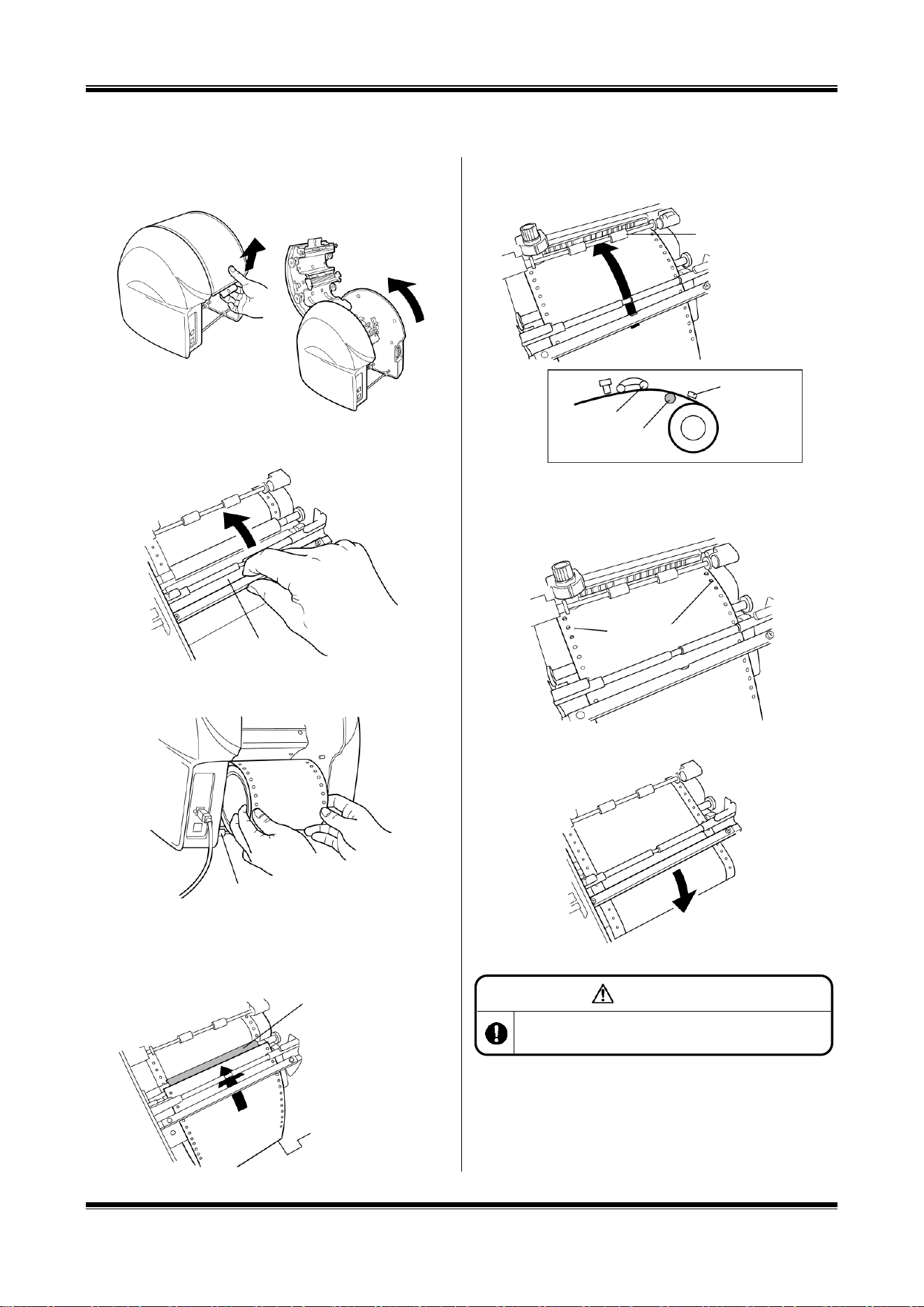
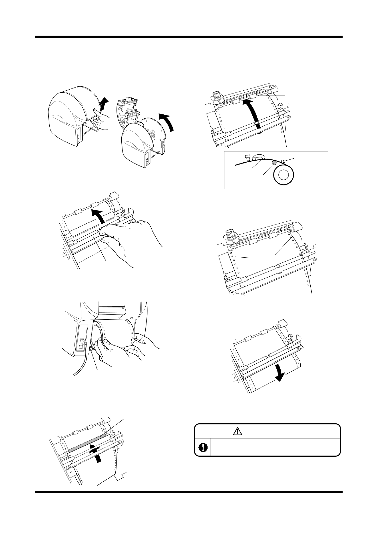
3. Working with the Tape roll
Loading the Tape roll
1. After turning off the power, pull up the door cover
opening/closing lever to open the door cover.
2. Lift up the dust removal lever (silver).
3. Place the Bepop tape roll on the tape roll holder.
4. Put the tape roll through under the dust removal lever
(silver).
5. Pull out the tape roll forward to put it through under two tape
roll retaining rollers.
6. Align the holes in the tape rolls with the right and left
sprocket pins.
7. Lower the dust removal lever (silver) to retain the tape roll.
8. Close the door cover until it “clicks” to lock.
Dust Removal Lever
(Silver)
Vinyl Holder
* Put it through over a
black roller.
Vinyl Retaining
Roller
Sprockets
Vinyl Retaining
Roller
Black Roller
Dust Removal
Lever (Silver)
CAUTION
When loading the vinyl, be sure to turn off the power.
Otherwise, you could be injured if the machine is activated
abruptly.
9
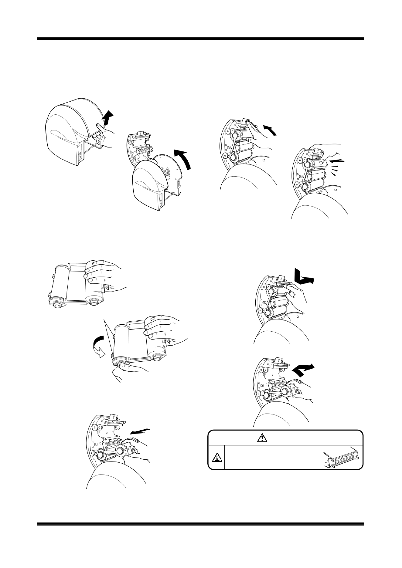
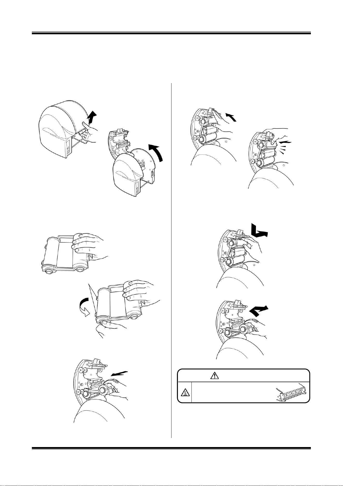
4. Working with the Ink Ribbon Cassette
Inserting the Ink Ribbon Cassette
Note : CPM-100G5 / HG5 printers work properly only with SL-R1xxT xxxxx-C (such as SL-R101T Black-C)
ribbon cassettes. For further details, please contact MAX Bepop CPM-100G5/HG5 distributors and dealers.
1. Pull up the opening/closing lever to open the door cover.
2. Holding the ink ribbon cassette so that its sponge faces
downward, turn the ribbon gear in the arrow-indicated
direction as shown in the figure to take up the slack of the
ink ribbon.
3. Fit the claws of the ink ribbon cassette into the slots in the
back of the door cover.
4. Turn the ink ribbon cassette upward, using the claws as
leverage. Push it in firmly until the ink ribbon locks with a
“click” sound.
Removing the Ink Ribbon Cassette from the
CPM-100G5/CPM-100HG5
5. Open the door cover. Pushing the snap of the ink ribbon
cassette, pull it out.
6. Lift the cassette upward and pull it out.
Claws
Click
WARNING
Do not touch the thermal head to prevent a
burn.
It could burn you.
10
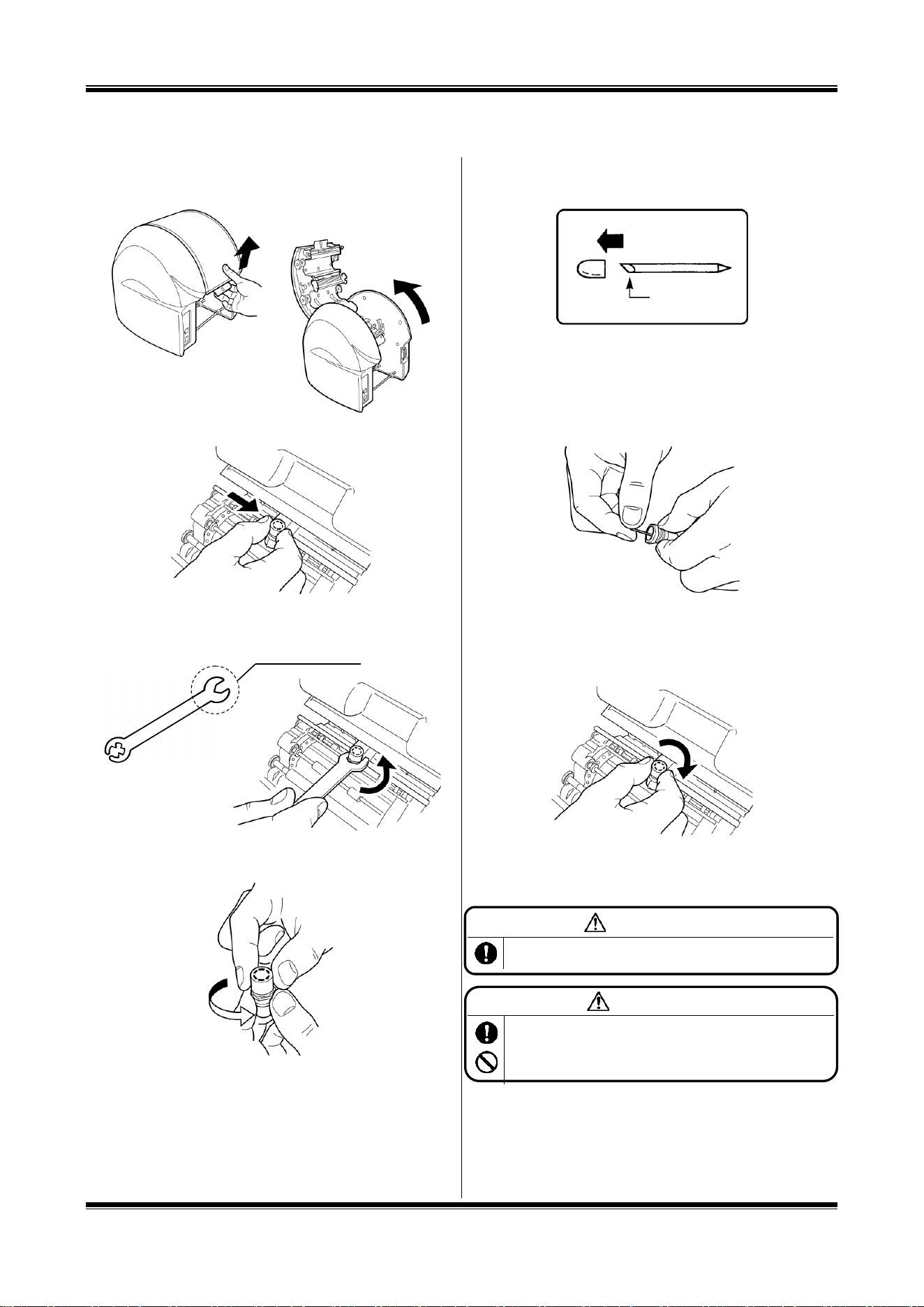
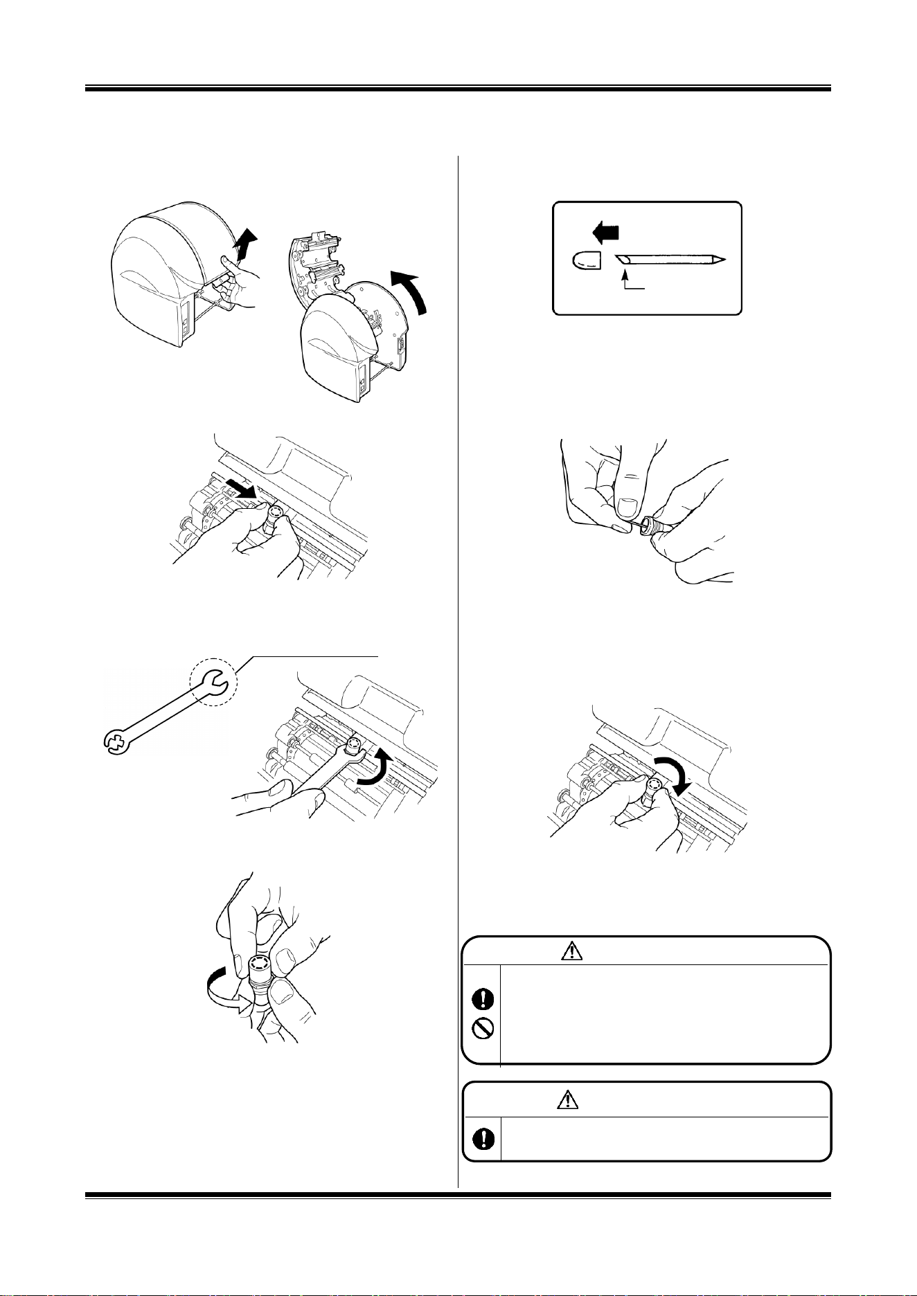
5. Working with the Cutting Tool
Installing (Replacing) the Cutting Tool
1. After turning off the power, pull up the opening/closing lever
to open the door cover.
2. Move the cutting head to the center manually.
3. Using an accessory spanner, turn the tool holder in the
counterclockwise direction to remove it. (Use the larger end
of the spanner.)
4. Turn the cap (top) of the tool holder in the counterclockwise
direction to remove it.
5. Prepare a new cutting tool (blade) and remove its protective
cap.
6. Holding a cutting edge (protective cap attached side)
downward, insert the blade lightly into the center of the
holder. DO NOT push the blade into the holder otherwise
this will not cut correctly.
* When replacing the blade, remove the old one first.
7. Tighten the holder cap. The share point will be projected
appropriately by tightening the cap firmly.
8. Clamp the tool holder manually onto the cutting head.
* When moving or carrying the printer, make sure to
remove the blade beforehand. Otherwise, the tip of the blade
may be damaged and result in improper cutting.
Blade
WARNING
Store the cutting tool (blade) out of the reach of children. If
swallowed accidentally, seek medical attention immediately.
CAUTION
Prior to mounting/dismounting the cutting tool (blade), be sure to
turn off the power. You could be injured if the machine is activated
abruptly. Do not touch the tip of the cutting tool (blade) to prevent
an injury.
Use the larger end.
11
[Preparar CPM-100G5/CPM-100HG5]
Asegúrese de leer
Indicaciones
El Manual y el producto vienen con varias indicaciones para asegurarse de que puede usar la máquina de forma correcta y segura.
A continuación encontrará las indicaciones:
ADVERTENCIA
LA NEGLIGENCIA PODRÍA OCASIONAR LA MUERTE O LESIONES GRAVES
DE UN TRABAJADOR.
PRECAUCIÓN
LA NEGLIGENCIA PODRÍA PROVOCAR LESIONES EN UN TRABAJADOR,
ÚNICAMENTE DAÑOS EN LA PROPIEDAD O LA PÉRDIDA DE DATOS
CREADOS.
Símbolos
Denota “a lo que debería estar atento”. Se da una precaución específica en este símbolo o
cerca de él.
Denota “lo que no debe hacer”. Se da una prohibición específica en este símbolo o cerca de
él.
Denota “lo que debe hacer”. Se da una instrucción específica en este símbolo.
12
[Precauciones de uso]
ADVERTENCIA
Nunca desmonte o remodele la máquina, ya que esto podría provocar un incendio, una descarga eléctrica u otros problemas.
No inserte ningún objeto extraño en la máquina, como dedos, bolígrafos, cables, etc., ya que podría provocar un incendio, una
descarga eléctrica o lesiones.
Use el cable de alimentación provisto.
No usarlo podría provocar un incendio o una descarga eléctrica.
Obtenga energía directamente de un tomacorriente. No coloque cargas múltiples en el tomacorriente dado que podría provocar
un incendio.
No modifique el cable de alimentación.
Nunca coloque un objeto pesado sobre un cable de alimentación, ya que este podría dañar el cable, lo que causaría un incendio
o una descarga eléctrica.
No use un cable de alimentación atado.
El calor emitido podría ocasionar un incendio o un fallo de funcionamiento. Asegúrese de desatar el cable de alimentación antes
de usarlo.
No conecte ni desconecte un enchufe con las manos mojadas. Podría recibir una descarga eléctrica.
No opere la máquina con las manos o ropa mojadas.
Podría recibir una descarga eléctrica.
No apoye papel o tela en la máquina cuando esté conectada a un tomacorriente.
Esto podría ocasionar un incendio o un fallo de funcionamiento.
Cuando desconecte el tomacorriente, sosténgalo directamente; nunca tire del cable de alimentación.
Esto podría dañarlo, lo que ocasionaría un incendio o una descarga eléctrica.
Asegúrese de no derramar agua ni químicos sobre las máquinas. Si agua u otro elemento ingresa por cualquier motivo,
desconecte el enchufe del tomacorriente de inmediato y comuníquese con el distribuidor para que lo repare. Si la máquina se
usa en tal estado, podría fallar o provocar un incendio o una descarga eléctrica.
Nunca coloque la mano o un objeto dentro de la sección de corte, ya que puede ocasionar fallos en el funcionamiento de la
máquina y lesiones personales.
Utilice la máquina solo en el voltaje de suministro indicado; el uso de cualquier otro voltaje podría ocasionar un incendio o fallos.
Asegúrese de poner a tierra la máquina.
De lo contrario, si ocurriera un cortocircuito, este podría provocar un incendio o una descarga eléctrica.
Limpie el enchufe regularmente.
El polvo acumulado durante mucho tiempo podría provocar un incendio o fallos.
Mantenga la herramienta de corte (la cuchilla) fuera del alcance de los niños. En caso de que se la traguen, busque atención
médica de inmediato.
No use la máquina si muestra indicios de un problema, como humo, ruido anormal u olor fétido, ya que dicho uso podría
provocar un incendio o una descarga eléctrica. En ese caso, desconecte el enchufe del tomacorriente de inmediato y
comuníquese con el distribuidor para que la repare.
PRECAUCIÓN
No comparta un tomacorriente con otro dispositivo (aire acondicionado, refrigerador, microondas, equipo de automatización de
oficina, etc.) que requiera gran capacidad. Esto podría disminuir el voltaje de suministro y resultar en el mal funcionamiento de la
máquina.
Instale la máquina sobre una superficie plana. No la instale en un lugar inestable, como por ejemplo, sobre una plataforma poco
firme o superficie inclinada. La máquina podría caerse y provocar lesiones o desperfectos.
No use la máquina bajo luz solar directa, en un lugar caluroso y húmedo o cuando haya condensación.
Podría provocar funcionamiento inestable o un fallo de funcionamiento.
No coloque papel o tela en la máquina, ya que podría provocar un incendio o fallos.
Nunca toque el cabezal térmico. Luego de imprimir está muy caliente y podría causarle quemaduras. Además, si el cabezal
térmico está accionado, podría ocasionar problemas.
Limpie el enchufe regularmente, ya que el polvo acumulado con el tiempo podría ocasionar un incendio o fallos.
Cuando desconecte el enchufe, sosténgalo directamente; nunca tire del cable de alimentación. Esto podría dañarlo y ocasionar
un incendio o una descarga eléctrica.
Cuando no pueda imprimir o cortar de forma adecuada a causa del atasco de un vinilo adhesivo, una cinta entintada o la
13
presencia de un objeto extraño dentro de la máquina, asegúrese de apagar el suministro de energía antes de eliminar el atasco.
De lo contrario, podría lesionarse por la activación abrupta de la máquina.
Cuando abra o cierre la tapa, tenga cuidado de que la mano, etc. no quede atrapada.
Cuando mueva la máquina, asegúrese de desconectar el enchufe del tomacorriente, cerrar la tapa y agarrar los laterales del
cuerpo para transportarlo. De lo contrario, podría dañar el enchufe o el cable y ocasionar un incendio o una descarga eléctrica,
así como también provocar lesiones o fallos de funcionamiento.
Cuando reemplace la herramienta de corte (la cuchilla) o monte/desmonte un vinilo, asegúrese de apagar el suministro de
energía. De lo contrario, podría lastimarse a causa de la activación abrupta de la máquina.
Tenga en cuenta que el borde cortante de la cuchilla de repuesto es muy filoso.
No toque la punta de la herramienta de corte (la cuchilla) o podría lastimarse.
Cuando no use la máquina durante mucho tiempo, como feriados consecutivos, asegúrese de desconectar el enchufe del
tomacorriente, por seguridad.
Los datos almacenados en una computadora personal no se pueden almacenar de forma permanente. No seremos
responsables de los daños ocasionados por pérdida de datos atribuibles a fallos o reparaciones, ni por pérdida de ganancias.
No toque directamente el conector con la mano. La electricidad estática puede ocasionar problemas.
Descargos de responsabilidad
MAX no será responsable de ningún daño que ocurra como resultado de no seguir las
instrucciones en este manual, daños y pérdida de ganancias por no poder usar la máquina
(fallos de funcionamiento) ni ningún daño secundario relevante.
ESPECIFICACIONES DEL PRODUCTO
Producto
CPM-100G5
CPM-100HG5
Sección de la
impresora
Método de impresión
Transferencia térmica
Densidad de impresión
203dpi
400dpi
Velocidad de impresión
25 mm/seg. (1”/seg.)
Sección de
corte
Resolución
0,025 mm/paso (0,001”/paso)
Velocidad de corte
120 mm/seg. (4,7”/seg.) al máximo
Rango de producción máximo
100 mm (3,9”) x 2000 mm (78,7”)
Interfaz
USB2.0 de velocidad
máxima
USB2.0 de velocidad máxima
LAN 10baseT/100baseTX
Entorno de trabajo
Temperatura: 10-35C (50-95°F),
Humedad: 35-80 % (No se permite condensación de rocío)
Fuente de alimentación
AC 100 - 240 V 50/60 Hz 1A
Consumo de energía
85 W
Dimensiones externas
330 mm (13,0”) x 320 mm (12,6”) x 320 mm (12,6”)
(Ancho) x (Profundidad) x (Altura)
Masa (solo el cuerpo principal)
9 kg (19,8lbs.)
*El diseño, las especificaciones y demás están sujetos a cambios sin previo aviso.
14
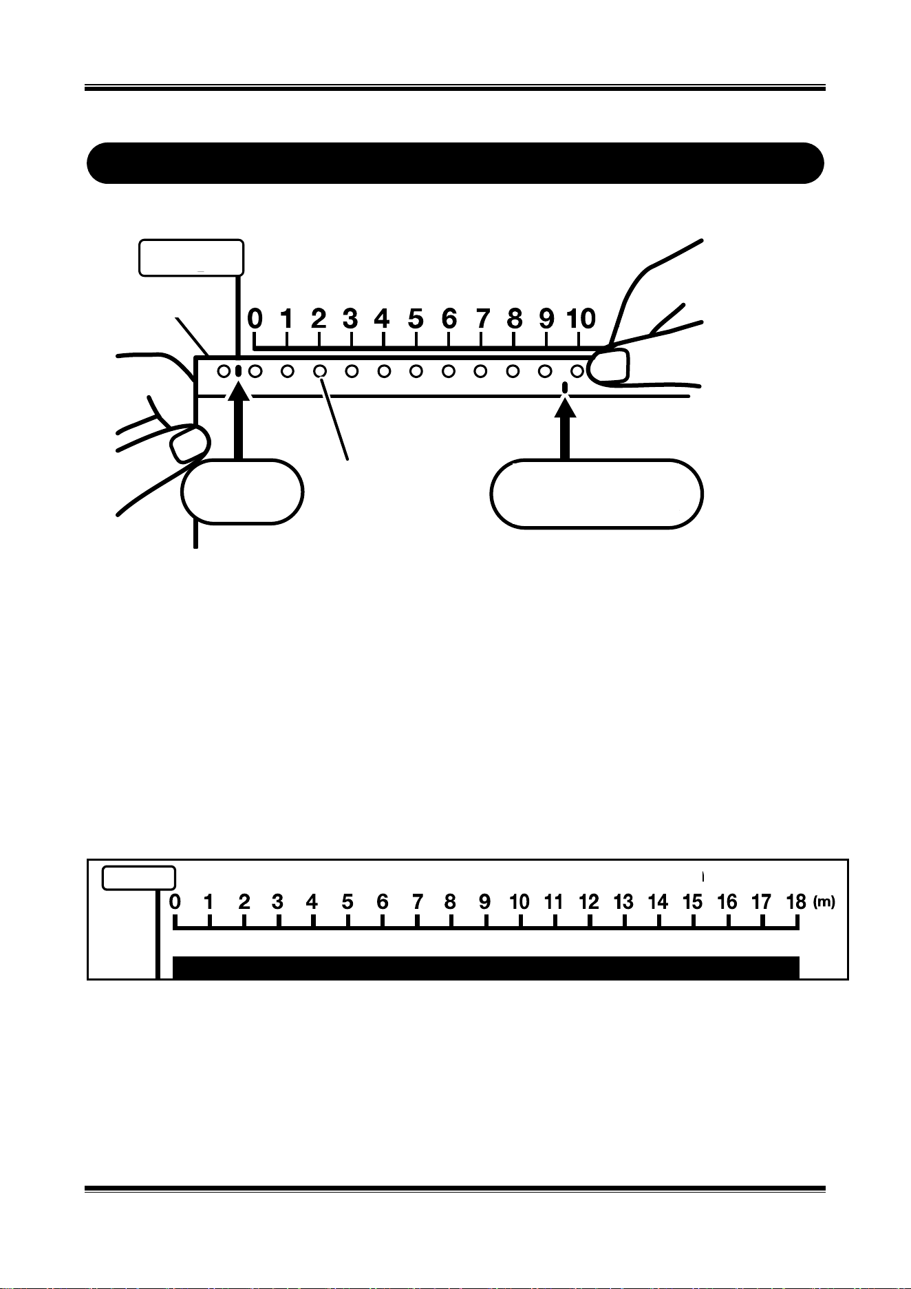
Origen
Regla para verificar la longitud de la cinta restante
¡
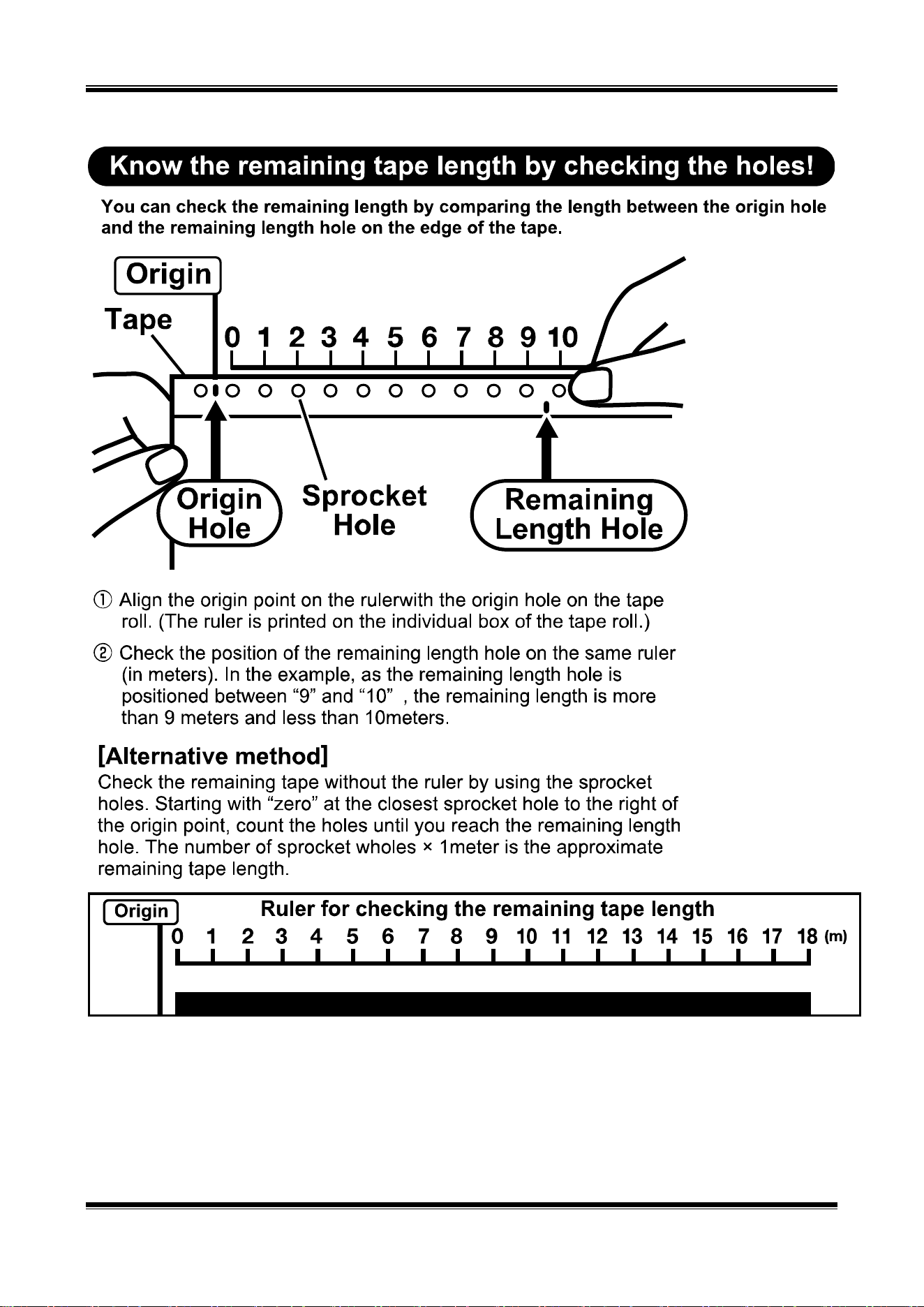
Conozca la longitud restante de la cinta revisando los orificios!
Compare la longitud entre el orificio de origen y el orificio de longitud restante en el borde de la cinta
para poder verificar la longitud restante.
Origen
Cinta
Orificio de
origen
Orificio
dentado
Orificio de
longitud restante
(1) Alinee el punto de origen en la regla con el orificio de origen en el rollo de cinta.
(La regla está impresa en la caja individual del rollo de cinta).
(2) Verifique la posición del orificio de longitud restante en la misma regla (en
metros). En el ejemplo, dado que el orificio de longitud restante se ubica entre “9” y
“10”, la longitud restante es de más de 9 metros y menos de 10.
[Método alternativo]
Verifique la cinta restante sin la regla mediante los orificios dentados. Comience con
“cero” en el orificio dentado más cercano a la derecha del punto de origen y cuente
los orificios hasta que alcance el orificio de longitud restante. La cantidad de orificios
dentados × 1 metro es la longitud aproximada de la cinta restante.
15
1. Confirmación del contenido del paquete
Abra el paquete y confirme que se incluyen todos los siguientes elementos.
<1> CPM-100G5/CPM-100HG5
<2> Cable de CA
<3> Cuchilla (1 unidad)
<4> Pinzas
<5> Escobilla de goma
<6> Portaherramientas
(Se adjunta con el
envío)
<7> Llave de sustitución
del
portaherramientas
<8> CD de software
de aplicación
<9> Manual de
instalación
(este manual)
2. Unidades del componente y sus funciones
[Parte delantera del cuerpo principal] [Parte posterior del cuerpo principal]
[Funciones de las teclas principales]
Tecla de alimentación : Se utiliza para encender/apagar el suministro de energía.
Teclas de alimentación de rollo de cinta : Se utiliza para alimentar el rollo de cinta.
Lámpara LED : Se ilumina en verde cuando el interruptor de alimentación está encendido.
Se ilumina o parpadea en rojo cuando le informa que hay un error.
Cubierta de la puerta
Salida de vinilo
Lámpara LED
Dial de control de presión de corte
Tecla de tijeras
Manija (derecha e izquierda)
Palanca de apertura/cierre
Cabeza térmica
Herramienta de corte
Cabezal de corte
Retenedor de vinilo
Rueda dentada
Palanca de extracción
de polvo (plateada)
Conector de
alimentación
Soporte de vinilo
Conector USB
Conector LAN
(Solo CPM-100HG5)
Tecla de alimentación de vinilo (atrás)
Tecla de alimentación de vinilo (adelante)
Tecla de alimentación
16
3. Trabajar con el rollo de cinta
Cargar el rollo de cinta
1. Después de desconectar la alimentación, tire de la palanca
de apertura/cierre de la tapa de la puerta para abrirla.
2. Levante la palanca de eliminación de polvo (plateada).
3. Coloque el rollo de cinta Bebop en el soporte del rollo de
cinta.
4. Pase el rollo de cinta por debajo de la palanca de
eliminación de polvo (plateada).
5. Tire del rollo de cinta hacia adelante para colocarlo debajo
de dos rodillos de retención del rollo de cinta.
6. Alinee los orificios en los rollos de cinta con los pasadores
de los dientes de las ruedas derecho e izquierdo.
7. Baje la palanca de eliminación de polvo (plateada) para
retener el rollo de cinta.
8. Cierre la tapa de la puerta hasta que “haga clic” para
bloquearla.
PRECAUCIÓN
Cuando cargue el vinilo, asegúrese de apagar el suministro de
energía. De lo contrario, podría lesionarse si la máquina se
activa de forma abrupta.
Palanca de
extracción de polvo (plateada)
Soporte de vinilo
* Colóquelo a través de
un rodillo negro.
Rodillo de retención
de vinilo
Ruedas dentadas
Rodillo de retención
de vinilo
Rodillo negro
Palanca de
extracción de
polvo (plateada)
17
4. Trabajar con el casete de cinta de tinta
Insertar el casete de cinta de tinta
Aviso: Las impresoras CPM-100G5 / HG5 funcionan correctamente solo con casetes de cinta SL-R1xxT
xxxxx-C (como por ejemplo SL-R101T Black-C). Para obtener más información, comuníquese con los
distribuidores y vendedores de MAX Bepop CPM-100G5/HG5.
1. Tire de la palanca de apertura/cierre para abrir la tapa de la
puerta.
2. Sostenga el casete de cinta de tinta de modo que la
esponja quede hacia abajo y gire el engranaje de la cinta en
la dirección indicada por la flecha, como se muestra en la
figura, para compensar la holgura de la cinta de tinta.
3. Coloque las garras del casete de cinta de tinta en las
ranuras de la parte posterior de la tapa de la puerta.
4. Gire el casete de cinta de tinta hacia arriba, usando las
garras como palanca. Introdúzcalo firmemente hasta que la
cinta de tinta se bloquee con un “clic”.
Quitar el casete de cinta de tinta de
CPM-100G5/CPM-100HG5
1. Abra la tapa de la puerta. Empuje el broche del casete de
cinta de tinta y sáquelo.
2. Levante el casete hacia arriba y sáquelo.
ADVERTENCIA
No toque el cabezal térmico a fin de evitar
quemaduras. Podría quemarse.
Garras
Clic
18
5. Trabajar con la herramienta para cortar
Instalación (reemplazo) de la herramienta de corte
1. Después de desconectar la alimentación, tire de la palanca
de apertura/cierre para abrir la tapa de la puerta.
2. Mueva el cabezal de corte al centro de forma manual.
3. Con una llave de accesorio, gire el portaherramientas en el
sentido contrario a las agujas del reloj para quitarlo. (Utilice
el extremo más grande de la llave inglesa).
4. Gire la tapa (superior) del portaherramientas en el sentido
contrario a las agujas del reloj para quitarlo.
5. Prepare una nueva herramienta de corte (cuchilla) y quite la
tapa protectora.
6. Sostenga un filo (con la tapa protectora unida) hacia abajo
e inserte la cuchilla ligeramente en el centro del soporte.
NO empuje la cuchilla hacia el soporte; de lo contrario, no
cortará correctamente.
* Cuando reemplace la cuchilla, primero deberá quitar la
vieja.
7. Ajuste la tapa del soporte. El punto compartido se
proyectará de manera adecuada ajustando firmemente la
tapa.
8. Sujete el portaherramientas de forma manual en el cabezal
de corte.
* Cuando mueva o transporte la impresora, asegúrese de quitar
la cuchilla de antemano. De lo contrario, la punta de la cuchilla
podría dañarse y no cortar de forma correcta.
ADVERTENCIA
Guarde la herramienta de corte (la cuchilla) fuera del alcance de
los niños. En caso de que se la traguen accidentalmente, busque
atención médica de inmediato.
PRECAUCIÓN
Antes de montar o desmontar la herramienta de corte
(la cuchilla), asegúrese de apagar el suministro de
energía. Podría lesionarse si la máquina se activa de
forma abrupta.
No toque la punta de la herramienta de corte (la
cuchilla) a fin de evitar lesiones.
Utilice el extremo más
grande.
Cuchilla

27
[Installing the BepopPC EX Software]
Notes
1. MAX Co., Ltd. in Japan owns copyright to this software.
2. It is prohibited to use or reproduce part or all of this software and manual without prior consent of MAX.
3. This software and manual are only allowed to be used under a license agreement to be concluded at the time of installing this
software.
4. The data saved in a PC cannot be permanently saved. Note that we are not responsible for damage and lost profits by missing
data attributable to trouble, repair, and so on.
5. The information described in the software specifications and manual is subject to change without prior notice.
6. The names of organizations and individuals mentioned in the samples created with this manual are fictitious and have nothing to
do with the existing organizations and individuals.
Microsoft and Windows are the registered trademarks of U.S. Microsoft Corporation in the U.S.A. and other countries.
Other company names and product names that may be mentioned herein are the registered trademarks of their respective company.

28
6 What is Possible with BepopPC EX
Capable of using a True Type Font to create cut lettering.
* Some True Type Fonts may not be able to cut properly due to the creating method of a font data.
Capable of converting the data in the bitmap format (win.bmp format), such as a logo mark read with a scanner, etc., into a
unique outline data format (extension “pcf”), which can be output through BepopPC EX to register it as a symbol.
Capable of inserting the data from a CSV format file.
Capable of setting a serial number for an alphanumeric text.
Provided with a “Table” frame function.
Provided with a bordering function.
Capable of editing the created outline data. A desired output result is obtained by eliminating unnecessary peaks and correcting
a position.
* The corners and curves may not be properly cut only by converting the data read from the scanner into the outline data.
Capable of enclosing with a rectangular, oval, or polygonal frame line. The frame line width can be set in increments of 0.004”
(0.1 mm).
Provided with the example sentence data in the template function to enable quick creation by changing only characters based
on the example sentences.
Added 2-part tiled output.
For arrange text features, provided with an arch text function to arrange the characters in the form of arch, and a line text
function to gradually enlarge or contract characters.
Capable of printing on Bepop tape roll in up to 11 colors (transparent tape roll: no-print setting).
(Not so-called color print)
Capable of pasting an image file of other application.
Provided with monochromatic and color symbols. Use the registered graphic symbols and illustrations for your original signs.
By using a laminate ribbon at the time of printing, a thin protective layer is created on the surface of the printed tape roll,
preventing label characters from being worn off.
After pasting a laminate film to the surface of the printed tape roll with a manual-pasting laminate film or an optional laminate kit,
load the tape roll in the printer again and cut the frame in line with the label shape. This allows you to create the laminate labels
resistant to water, oil, chemicals and wearing off.

29
7 Important: Read before Installation
7.1 Environment of PCs Capable of Running with This Software
Use the PC compliant with the following conditions. Other PCs cannot be assured of their operations.
CPM-100G5
CPM-100HG5
Suggested specifications
Operating System : Windows 10 / 8.1 / 7HDD: Free space 100 MB or more
CD-ROM.
Required port
USB port
USB port/LAN port
7.2 Precautions for Installation
Please read the following restrictions and precautions for installing this software and the printer driver.
Warning and Restrictions
To install, it is necessary to log in as an “Administrator” or a member of an “Administrators”
group.
Restart after installation. In the case that multiple users are logged-in, carry out the installation
after the other users have logged off.
When installing into a PC connected to a network (in-house LAN/WAN, etc.), consult a network
administrator.
Install only the printer driver of the model used.
◆ Be sure to use an installer, which is activated with an included CD-ROM, to install or uninstall.
30
8 Installation and Uninstallation
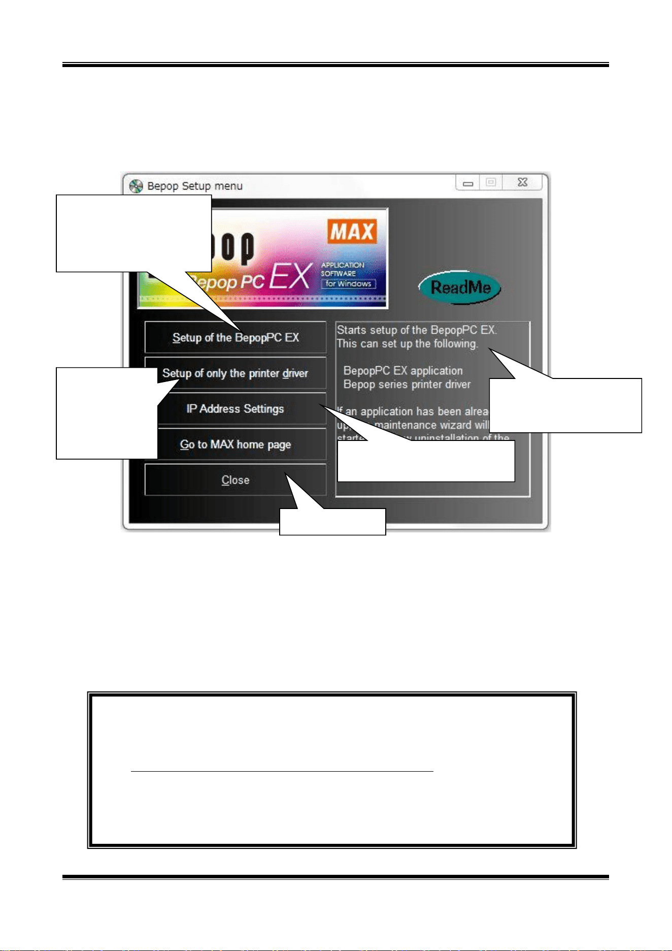
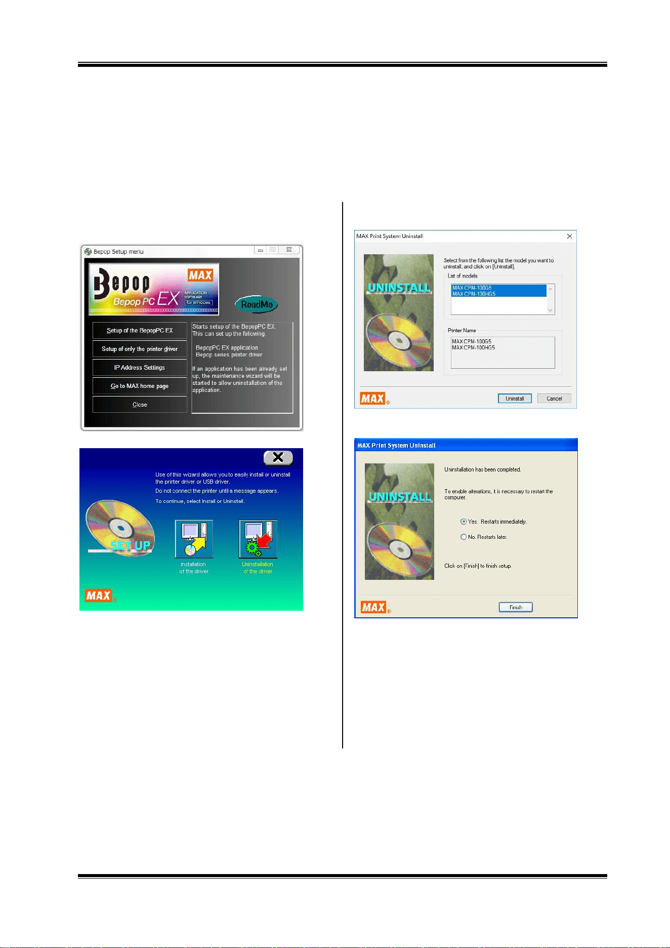
8.1 Setup Menu
The Setup menu activated by the included CD-ROM has the following functions:
[Important] When Upgrading
When installing from this CD-ROM into the PC where BepopPC EX and the printer driver have been installed, be
sure to uninstall the old-version BepopPC EX software and the printer driver, and then, reinstall them.
Uninstall BepopPC software and the printer driver separately. See the following pages.
Uninstalling BepopPC : Page 30
Uninstalling the Printer Driver : Page 32
Install BepopPC EX, and desired
printer driver. Normally, select
this button. Uninstallation of
BepopPC EX is also done
through this button.
Install (or uninstall)
only the printer
driver used. Use this
button when adding
only the printer
driver.
Exit the Setup menu.
This area displays a description
of the button indicated by the
cursor.
Set up the IP address when using by
LAN connection.
31
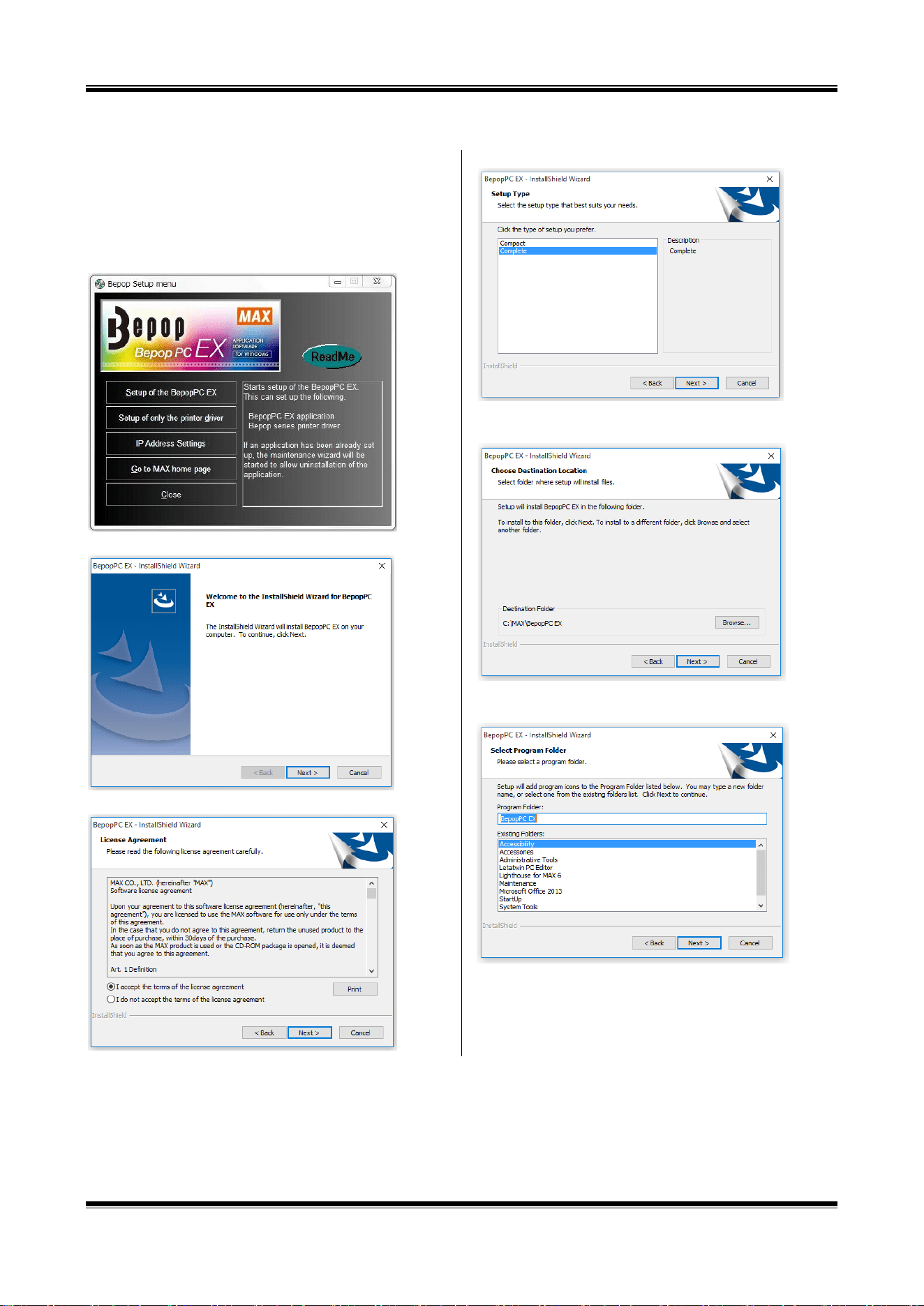
8.2 Installing BepopPC EX Software
1 Prior to installing Bepop PC EX software, terminate other
application software and resident-type software such as
virus scan software.
2 Set the included CD-ROM in the PC.
Click on “Continue” in the user account management screen.
3 The Bepop Setup menu appears. Click on [Set up of the
BepopPC EX].
4 Click on [Next].
5 Read the License Agreement and click on [Yes] if you agree.
6 Select “Complete” and clock next.
7 Click “Next”. (choose the appropriate destination folder, if
necessary.).
8 Check that the program folder is “BepopPC EX”, and then
select “Next”
.
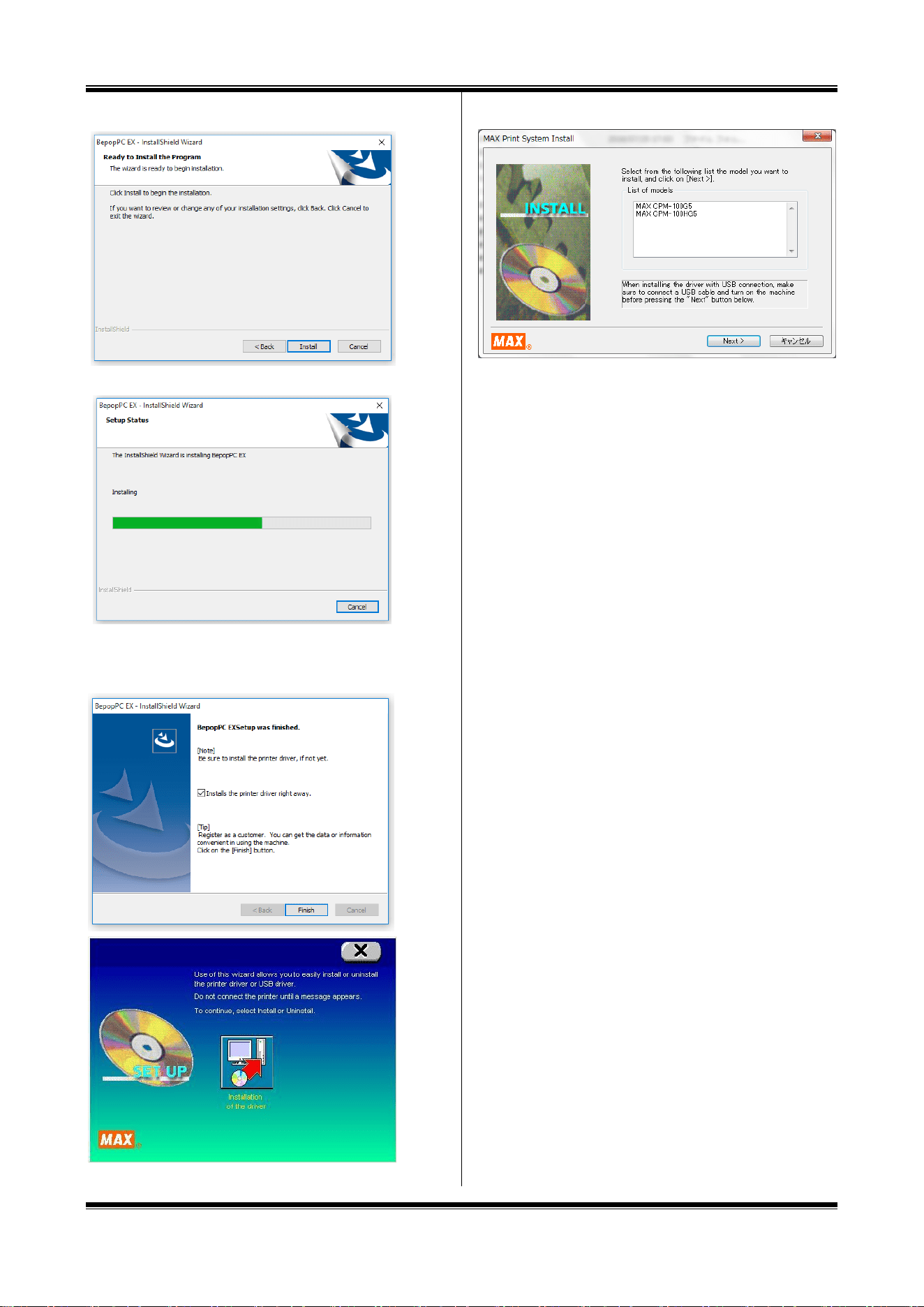
32
9 Click the “Install” button.
10 The installation process will begin.
11 Confirm that it is checked in the box for “Installs the printer
driver right away.” and click on [Finish].
12 Select the model from List of Models, and click on [Next].
*When installing for use with a USB port, connect printer to
the USB port and turn on the machine before clicking “Next”.
33
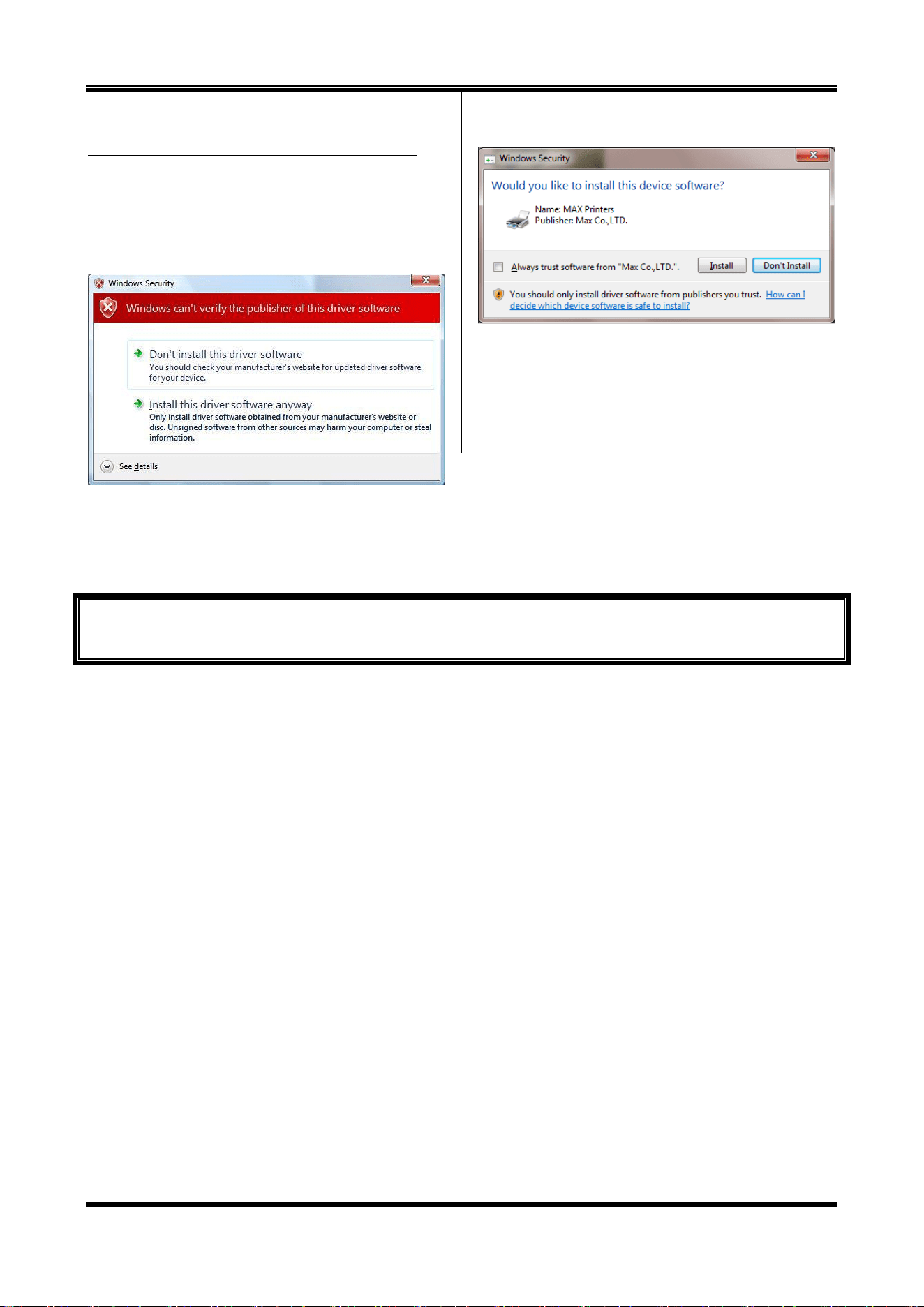
[Messages displayed in procedures below]
The following messages may appear in the procedures below.
Although following warning message is displayed, the product can be
used without problems.
Once the message appears, click on [Install this driver software anyway],
[Continue Anyway] or [Yes].
* These message are omitted in the procedural description below.
(Message displayed for Windows 7)
(Message displayed for Windows 10 / 8.1)
Now, you are finished with installation.
Let us start and run BepopPC EX.
34
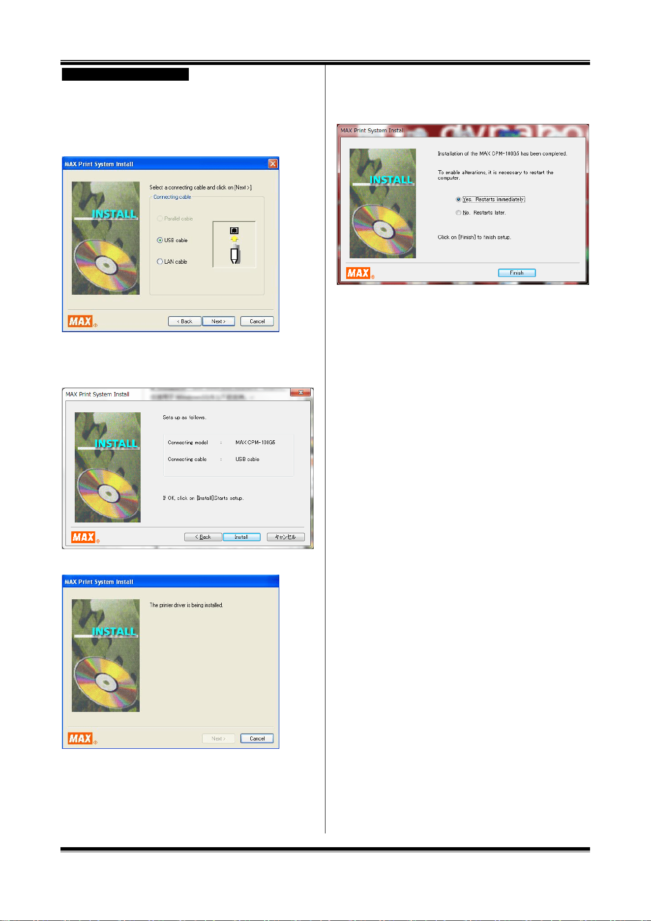
USB Cable Driver Installation
1 Connect the USB cable, and then turn on the Bepop
machine.
2 Select “USB cable” and click on the [Next] button.
* Only selectable cables are displayed depending on the OS used,
model connected, and PC used.
3 Click on [Install].
* The screen shows that the USB cable has been selected for the
Bepop machine.
4 Installation of the driver and port monitor starts automatically.
* “No reply” may be displayed. Wait for some time.
5 Select “Yes. Restarts immediately” and click [Finish].
* If there is any application software left unterminated at the time of
starting installation, click on [No], exit the application, and then, restart
the PC.
6 Restart the PC. You are finished with installation.
* BepopPC EX and the Bepop machine operate successfully only after
restarting the PC. Be sure to restart it.
35
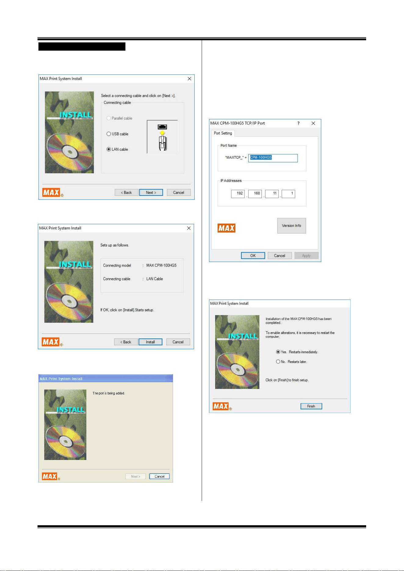
LAN Cable Driver Installation
12 Select “LAN cable” and click on the [Next] button.
* Only selectable cables are displayed depending on the OS used,
model connected, and PC used.
13 Click [Install].
* The screen shows that the Bepop machine has been selected.
14 Installation of the driver and port monitor starts automatically.
* “No reply” may be displayed. Wait for some time.
15 Set the port name and an IP address for the PC side.
Enter the port name and IP address, and click on [OK].
* For the appropriate IP address , inquire a network administrator of
your organization.
* The IP address to be set has to be consistent with the upper 9 digits
of the IP address (three 3-digit divisions) of the PC used. For the last
3 digits, assign an unused number not duplicating other connected
device.
* When using multiple units of printers, set different port names and IP
addresses.
16 Select “Yes. Restarts immediately” and click [Finish].
* If there is any application software left unterminated at the time of
starting installation, click on [No], exit the application, and then, restart
the PC.
17 Restart the PC.
* BepopPC EX and the Bepop machine operate successfully only after
restarting the PC. Be sure to restart it.
18 It is necessary to set the IP address of the printer body.
Set it according to “9 Setting the IP Address of the
CPM-100HG5” (Page 31).
36
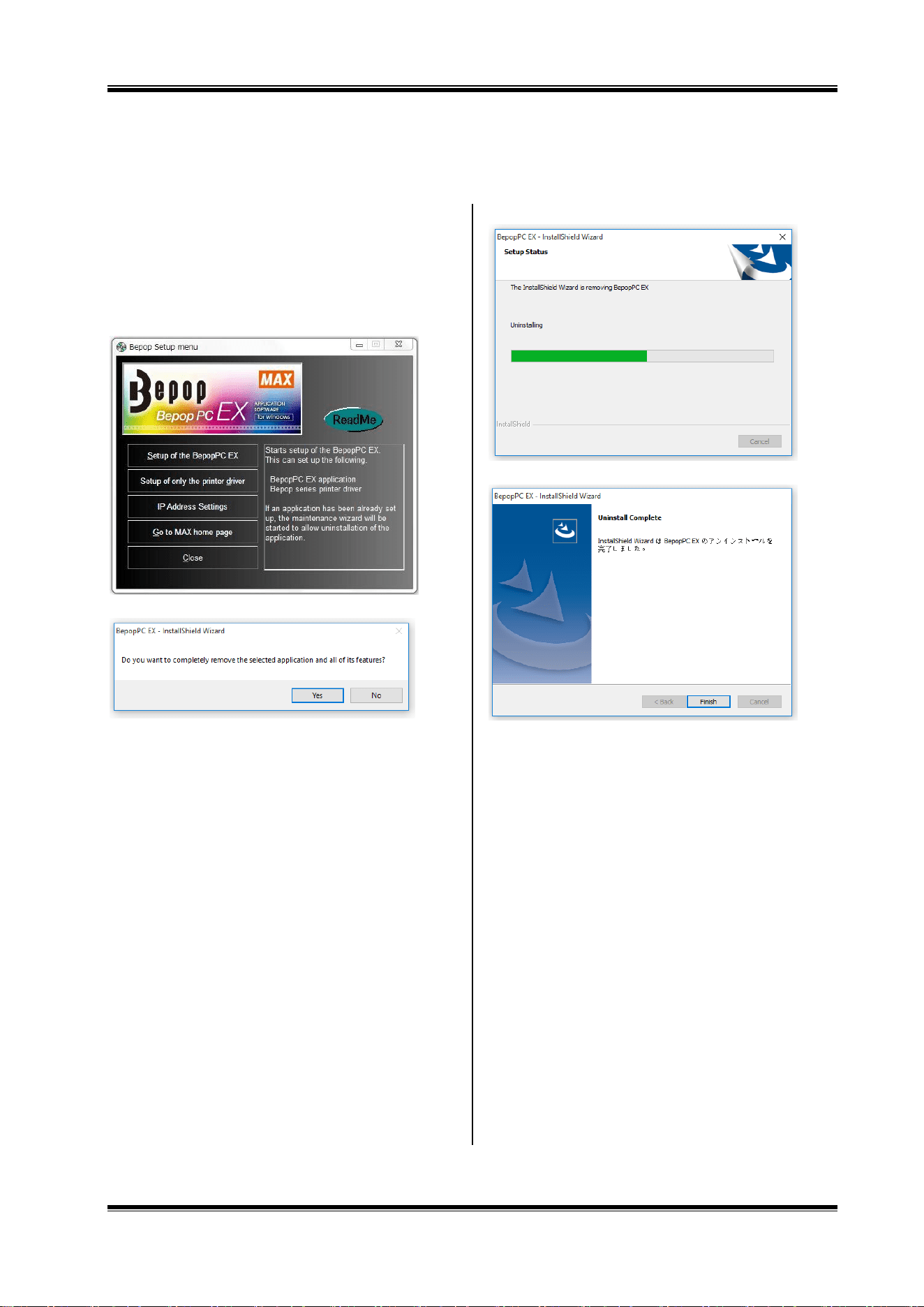
8.3 Uninstalling BepopPC EX
To uninstall BepopPC EX software, such as upgrading from the old version, follow the procedure below:
1 Prior to installing Bepop PC EX software, terminate other
application software.
2 Set the included CD-ROM in the PC.
Click on “Continue” in the user account management
screen.
3 The BepopPC EX Setup menu appears. Click on [Set up
of the BepopPC EX].
4 Click on [OK].
5 Uninstallation of BepopPC EX starts.
6 Click on [Finish].
37
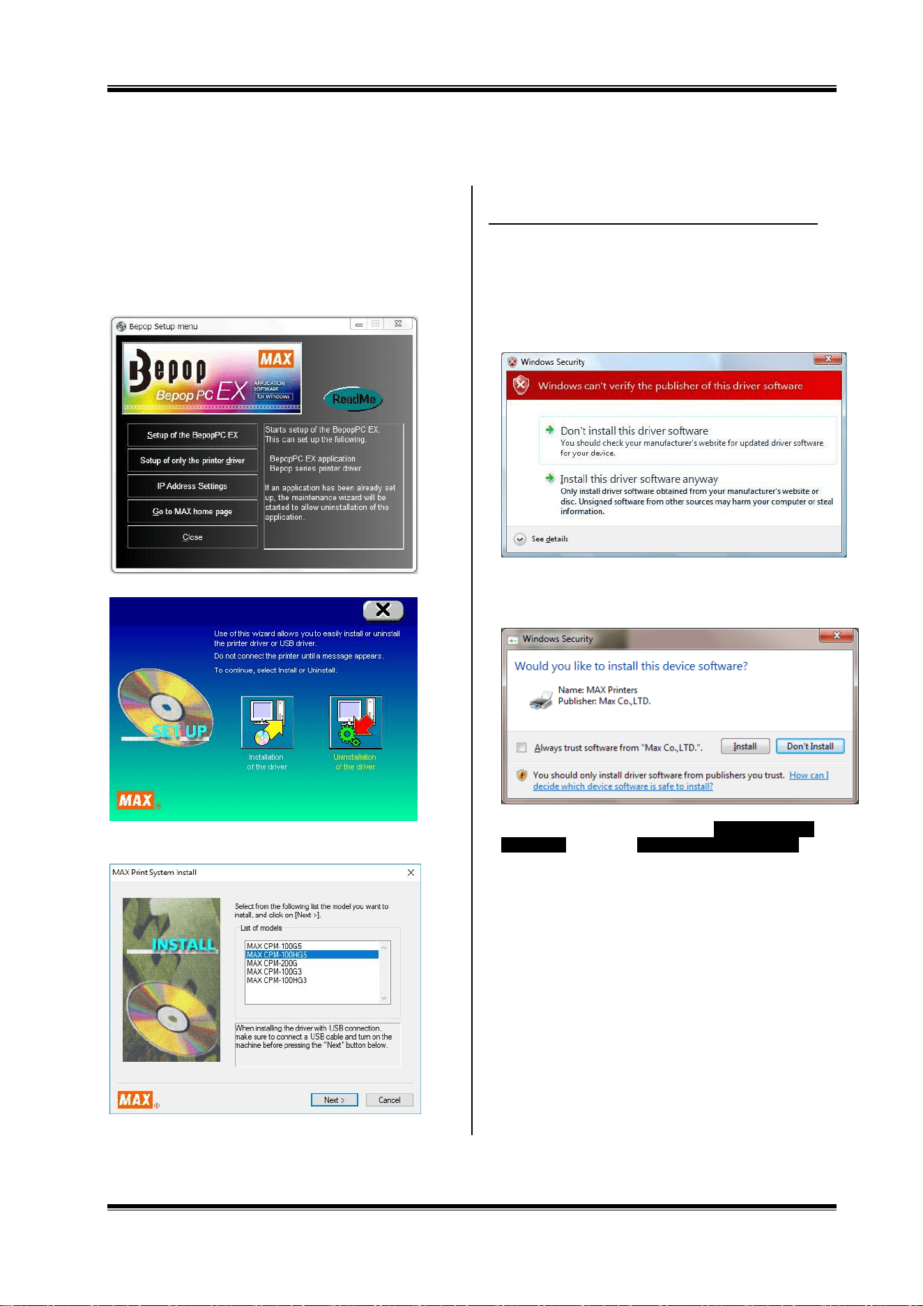
8.4 Installing only the Printer Driver
To install only the printer driver for Bepop, be sure to follow the procedure below:
1 Prior to installing Bepop PC EX software, terminate other
application software.
2 Set the included CD-ROM in the PC.
Click on “Continue” in the user account management
screen.
3 The BepopPC EX Setup menu appears. Click on [Set up
only the printer driver].
4 Click on [Installation of the driver].
5 Select the model from the list of models and click on
[Next].
[Messages displayed in procedures below]
When installed with Windows, the following messages may appear in
the procedures below.
Although the following warning message is displayed, our product
can be used without problems.
Once the message appears, click on [Install this driver software
anyway], [Continue Anyway] or [Yes].
These message are omitted in the procedural description below.
(Message displayed for Windows 7)
(Message displayed for Windows 10 / 8.1)
For the subsequent procedure, follow either USB Cable Driver
Installation on Page 26 or LAN Cable Driver Installation on
Page 27 to install.
38
8.5 Uninstalling the Printer Driver
To uninstall the printer driver, be sure to follow the procedure below.
[Precautions]
If Bepop has made output even once after starting the PC, the printer driver may not be uninstalled. Prior to
uninstalling it, restart the PC.
If uninstallation is implemented in other way, the system information saved in the PC is not deleted, possibly having an
effect on next installation.
1 Set the included CD-ROM in the PC.
2 The BepopPC EX Setup menu appears. Click on [Set up
only the printer driver].
3 Click [Uninstallation of the driver].
4 Select the Bepop machine to be uninstalled and click on
[Uninstall].
5 Check “Yes. Restarts immediately” and click on [Finish].
6 Restarting the PC finishes the uninstallation procedure.
* After uninstallation, be sure to restart the PC.
39
9 Setting the IP Address of the CPM-100HG5
It is possible to connect the CPM-100HG5 to a Local Area Network (LAN).
IP Address settings of the printer must be changed when using a LAN connection.
9.1 Restrictions for LAN Connection
When using the CPM-100HG5 by LAN connection, consult
the network administrator at the time of installation to your
computer.
Requests to the network administrator
It is possible to connect the CPM-100HG5 to your LAN.
Please follow the instructions below.
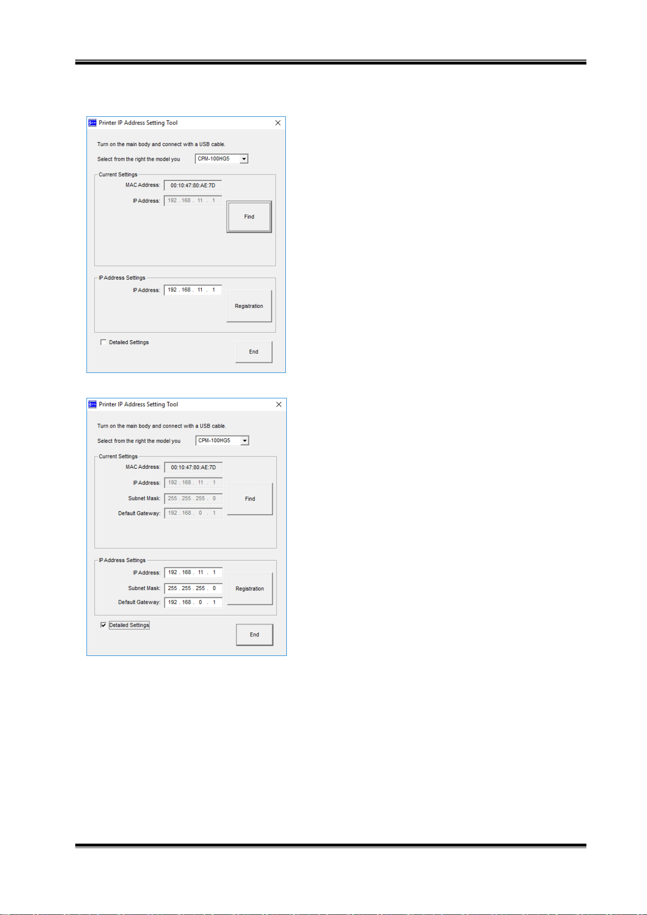
The default IP address of CPM-100HG5 is detailed
below.
Subject
Default setting
IP address
192.168.11.1
Subnet mask
255.255.255.0
Default gateway
192.168.0.1
* The following IP addresses cannot be used.
(1) 0. 0. 0. 0 (all 0)
(2) 255. 255. 255. 255 (all 255)
(3) 127. xxx. xxx. xxx (loopback address group)
(4) xxx. xxx. xxx. 255 (subnet broadcasts)
To change the settings of the CPM-100HG5, see 9.2
Setting the IP Address of the CPM-100HG5.
To install and use, it is necessary to log in as an
“administrator” or a member of an “Administrators”
group.
Restart after the driver installation. In the event that
multiple users are logged in, it will be necessary to
log-off before starting the installation.
CPM-100HG5 does not support DHCP and SNMP
management .
A single printer cannot be simultaneously installed as
both a USB port printer and a LAN printer.
In LAN connection, the PC and this machine can be
directly connected by using a crossover cable.
40
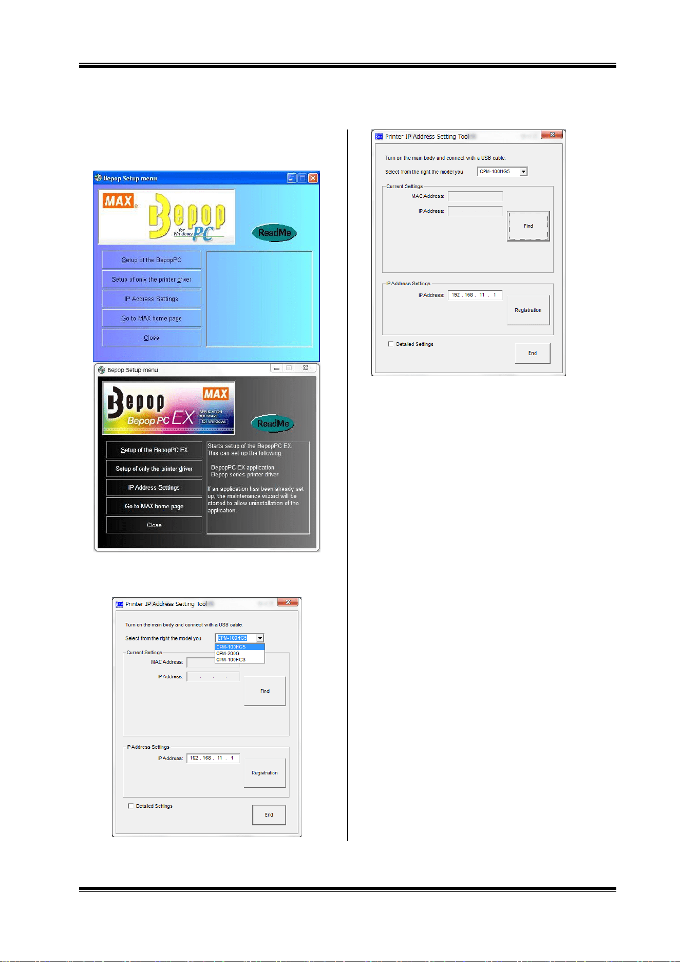
9.2 Setting the IP Address of the CPM-100HG5
* To set the IP address of the CPM-100HG5, connect the printer to the PC via a USB cable.
1 Set the included CD-ROM in the PC.
2 The BepopPC EX Setup menu appears.
Click on [IP Address Settings].
3 The IP address setting tool for the CPM-100HG5 appears.
Turn on the CPM-100HG5, connect it with the USB cable,
and select the model you want to set.
* By clicking “Find” button, the current MAC address and IP address
for the connected printer will be displayed. .
* The current value will appear in the IP address settings window.
41
4 Enter the IP address and click on [Registration].
Next, by clicking [End] button, the setting procedure is
completed. Enter the newly registered address when
installing the printer driver.
* By selecting the “Details” button, it is possible to change the
Subnet mask and Default gateway.
Now, the IP address setting procedure is completed.
42
10 Operation of BepopPC EX (1): Input and Output of
Characters
10.1 Entering the Texts
1 Start BepopPC EX.
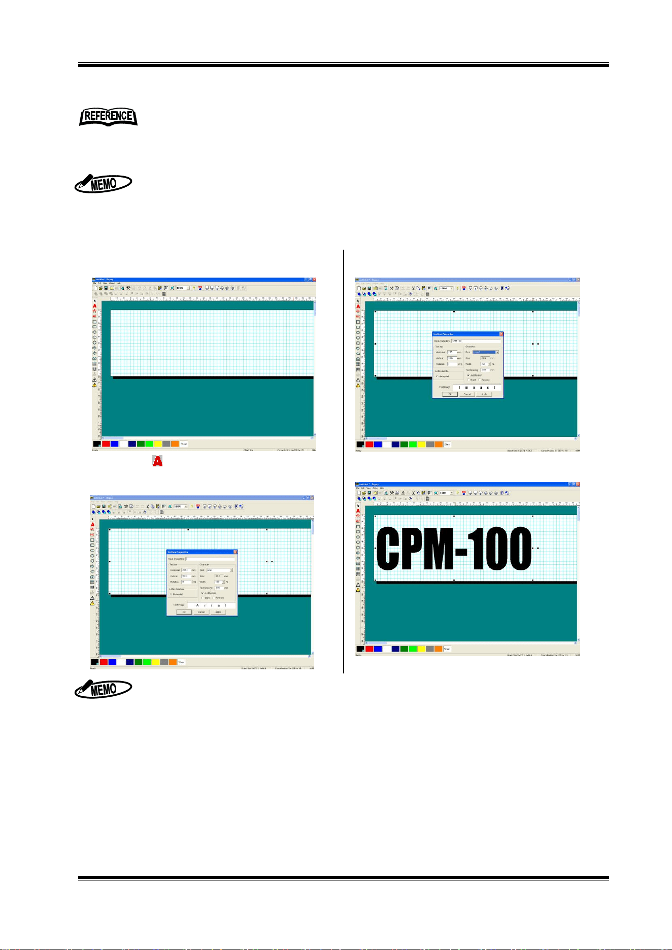
2 The “Layout” screen appears initially.
3 Click on to select a text box, and drag an area
where you want to draw the characters. The “Textbox
Properties” window is opened.
4 Input the characters into the “Input text”. Set other items
such as a font.
5 Click on the [OK] button to lay out the input characters in
the editing screen.
Only True Type fonts are available.
* For some True Type fonts, cutting may not be properly done, due to the font data structure.
When using this machine with a personal computer, available editing software is only this BepopPC EX software.
Other application software does not assure proper operation.
For details of operation, check the pdf manual of BepopPC EX software, which is installed in
the installation folder. See the Help function of this software.
The following description shows an example with the printing mode.
If selecting the cutting mode, the characters are displayed with out-line style, and color pallet and color
symbols are not available.
43
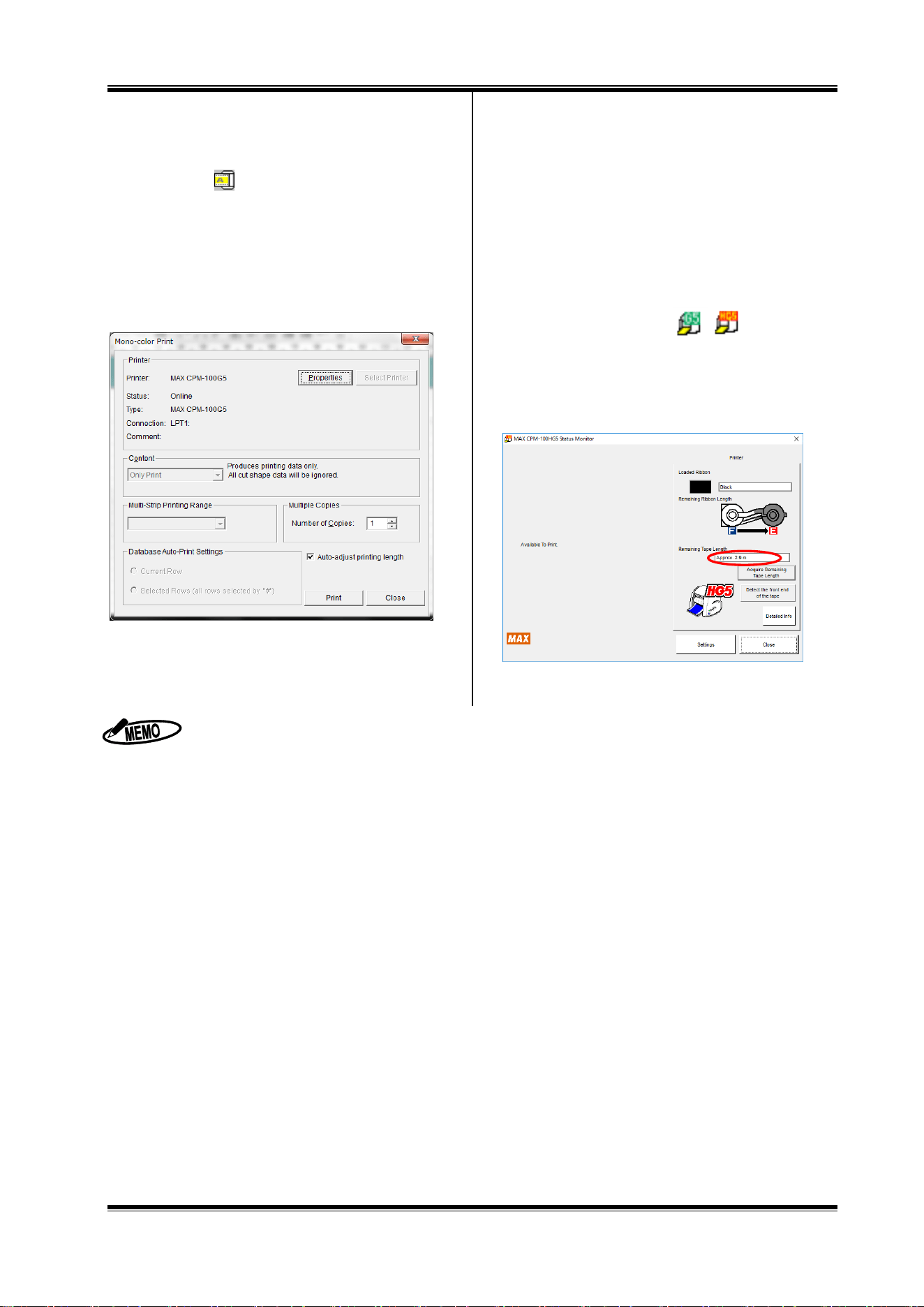
10.2 Outputting to Bepop
1 Set a tape roll in this machine.
2 Click on [ ].
3 Click on the [Start print] button.
4 Output starts.
After initial operation (feeds the tape roll by about 7.625”
(19 cm) and returns), the machine performs printing, and
cutting later.
10.3 Checking the Remaining Tape Roll
Length
The remaining length of the tape roll loaded into the
CPM-100G5/CPM-100HG5 can be checked with the status monitor
of the CPM-100G5/CPM-100HG5. This function can be
conveniently used for checking beforehand if the tape roll is long
enough for output length, and replenishing and managing the tape
roll.
1 Double-click on an icon [ ] located at the
lower right part of the PC to display the status monitor.
2 Click on the [Acquire Remaining Tape roll Length] button.
Feed the tape roll and acquire the remaining tape roll
length.
3 The approximate remaining tape roll length is displayed.
When setting a vinyl, you can feed/return it with Feed key.
CPM-100G5/CPM-100HG5: Feed key on the side of the machine
If you click on the [Properties] button in 10.2 Step 2 above, you can make detailed settings related to output.
To cancel output halfway, click the [Cancel Print] button of the status monitor, or turn off the
CPM-100G5/CPM-100HG5, click on the [Cancel Print] button of the status monitor to delete a print job, and turn on
the power again.
The remaining vinyl length may be displayed different from the actual length by 15 to 30 cm, depending on the
remaining meter value and vinyl loading condition. Once the vinyl is separated from the roll, the remaining vinyl length
is not correctly displayed.
Be sure to use the specified vinyl for the CPM-100G5/CPM-100HG5.
44
11 Operation of BepopPC EX (2): Import of Logo or
Mark
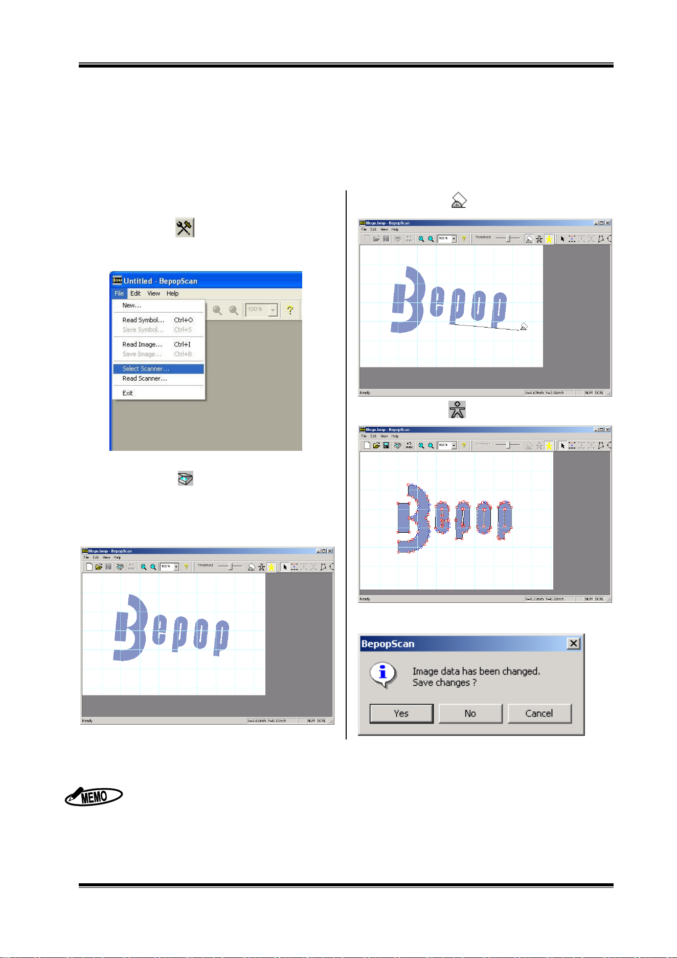
11.1 Scanning the Logo or Mark from the Scanner
1 Start BepopPC EX.
2 Click on the [OK] button in the “Setup sheet” screen.
3 Click on the [ ] button. BepopScan (Edit symbol
screen) starts.
* You can also operate by selecting “File” – “Edit symbol”
4 Open “File” – “Select Scanner.”
5 Select Scanner you want to use.
6 Click on the [ ] button to start selected scanner.
7 Place a logo or mark on the scanner to read it.
* For the scanner operating methods, see the instruction manual for
the scanner.
8 Once the scanner finishes scanning, a scanned logo or
mark appears in gray in the Edit symbol screen.
9 Click on the [ ] button and drag a line you want to
make horizontal to correct the tilt of the read logo.
10 Click on the [ ] button to outline it.
* The graphic data is converted into the data for Bepop.
11 Select “File” – “Exit”. Select “Yes” to save the original data
(bitmap data) imported from the scanner.
Only the scanners compliant with the TWAIN Standards are available.
Once “Select scanner” is selected in Step ③, you do not need to select it thereafter.
For the methods to operate the scannere, see the instruction manual for the scanner.
The suitable logos or marks are as follows:
The maximum logo or mark is bitmap data up to A4 size.
Use the logo or mark which has a clear graphic symbol to be scanned. <Black and white print or line-work>
(The data with a photo or a gradational representation may not be converted as you expect.)
Only a necessary portion is scanned.
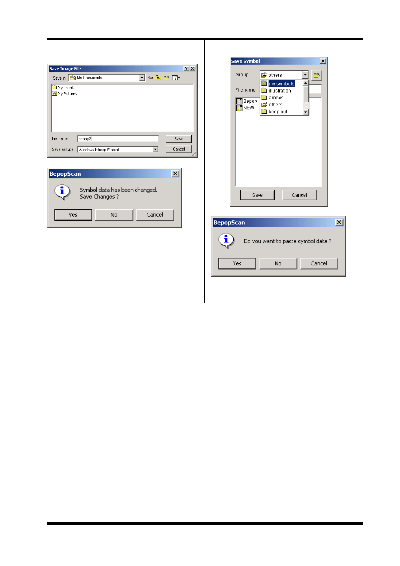
45
12 Select a location to save, name a file, and click [Save]
button.
13 Click [Yes] to save the outlined data.
14 Select a group name, name a file, and click [Save] button.
15 Click [Yes] button to paste to the editing screen.
16 The symbol data is laid out in the editing screen.
46
11.2 Inserting the Saved Symbol (When Using for BepopPC EX)
1 Select “Object” – “Insert Symbol.”
2 Select a group name and click a file name. A symbol
image appears on the right.
3 Click [Insert Symbol] button or double-click on the image.
It is inserted in the editing screen.
47
12 Troubleshooting
1. Troubles Related to Installation of the Printer Driver
When the printer driver cannot be installed, displaying a
message “Failed to install the printer driver.”;
1 Restart the PC.
2 Uninstall the printer driver according to “8.5 Uninstalling
the Printer Driver”.
3 Restart the PC.
4 Reinstall according to “8.4 Installing only the Printer
Driver”.
When the printer driver can be neither uninstalled nor
installed (when a print job is remaining);
1 Select “Start” to display “Printers and Faxes” and
double-click on the icon of MAX CPM.
2 If there still remains a document, select “Printer” ->
“Cancel All Documents”.
3 Uninstall again.
2. When printing fails, displaying no status monitor;
The printer driver has been successfully installed, but the
status monitor (a window to display remaining ink ribbon
length, remaining tape roll roll length and the printer status)
does not appear at the time of printing. An icon for the
standard printer is displayed on the task bar (normally icons
at the lower right of the screen), but the one for the CPM is
not.
Cause:
This is because the status monitor has not started or installation
of the status motor failed, which is implemented simultaneously
while installing the printer driver. A possible cause is an
operational effect of virus scan software.
Remedy
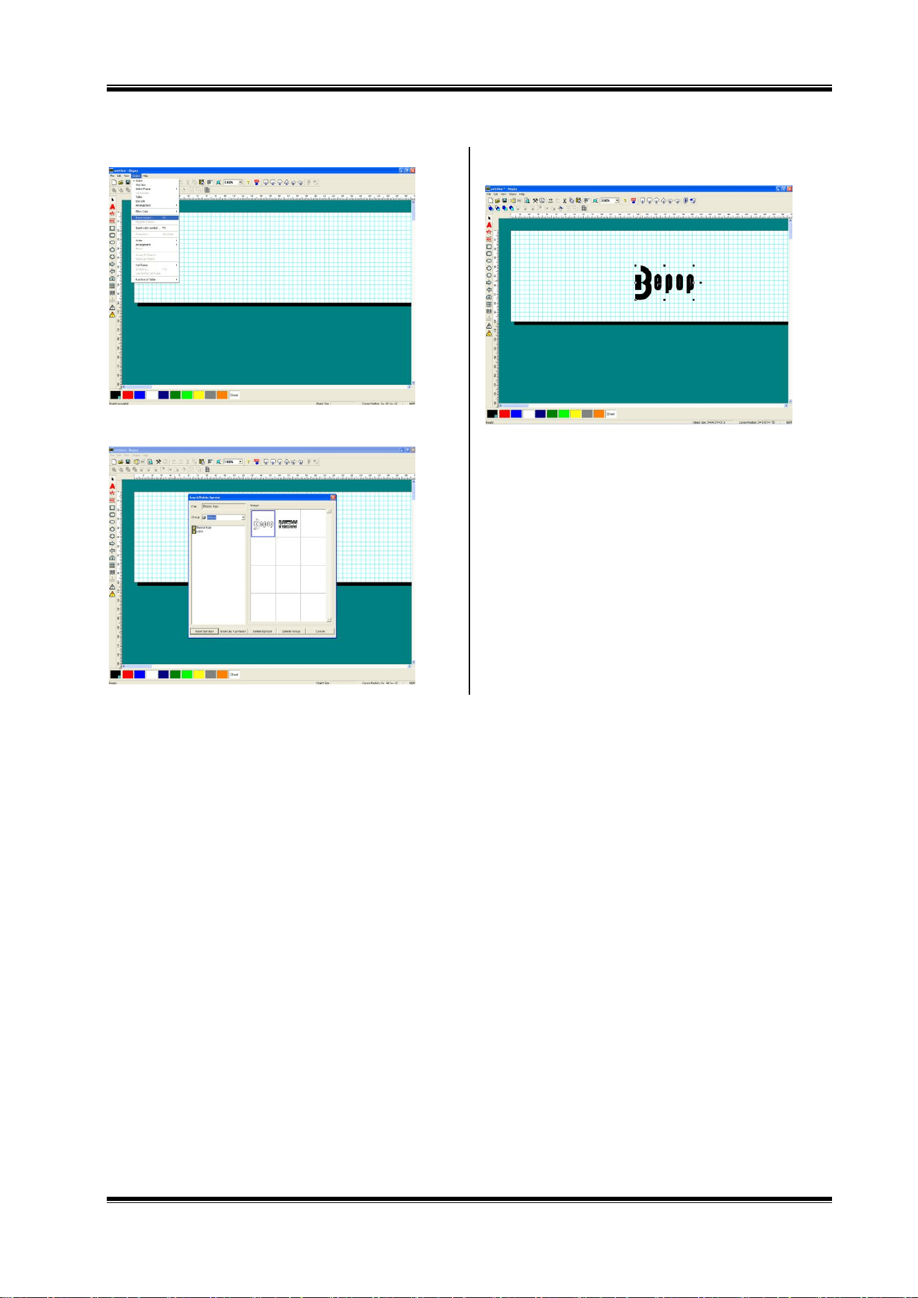
1 Checking the symptom
Select “Start” -> “Control Panel” -> (“Performance and
Maintenance”) -> “Administrative Tools” -> “Services” to
open a service window.
Check that the following is indicated in the name field.
(For the CPM-100HG5)
MAX CPM-100HG5 Option UI Manager
(For the CPM-100G5)
MAX CPM-100G5 Option UI Manager
If no name is indicated, this symptom applies.
* If the name is indicated, check if the status is “Start”. In case of
“Stop”, right-click on “Start”.
2 Check that if you have logged in with administrator authority.
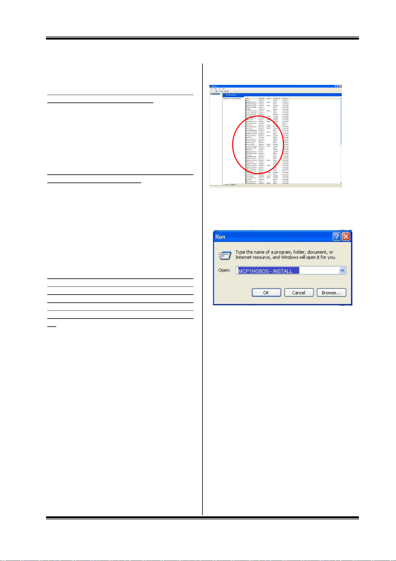
3 Install the status monitor manually.
Select “Start” -> “Run”.
As mentioned above, enter the following in the name field:
For the CPM-100HG5: MCP1HG5OS -INSTALL
For the CPM100G5: MCP1_G5OS -INSTALL
(There is a one-byte space before “-“. Enter all the characters
as one byte each.)
And click on the OK button.
The status monitor is installed.
* If an error (No file) is displayed, it is likely that there is an input
error in the name field.
48
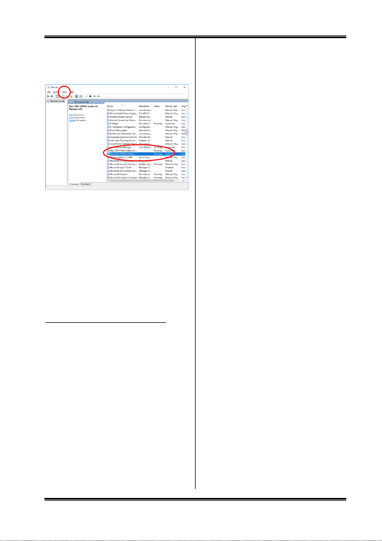
4 Checking method
Check that the following is included in the indicated service in 1.
Checking the symptom:
For the CPM-100HG5: MAX CPM-100HG5 Option UI Manager
For the CPM-100G5: MAX CPM-100G5 Option UI Manager
If Status = Start and Type of Startup = Auto, installation of the
status monitor is completed. (If it is manually installed with the
service window left opened, check after updating the display.)
If nothing is displayed now, repeat Steps 2 and 3 after restarting,
and uninstall the printer driver.
After restarting, repeat Steps 2 and 3, and implement regular
installation.
If regular installation fails, implement manual installation as
described in 3.
5 After installation is completed, restart.
3. Other Troubles
The printer cannot be recognized by LAN connection.
Check if the IP address of the printer has been set correctly.
The IP address of the PC port is set in installing the printer
driver.
It is also necessary to set the IP address for the printer main
body. Connect with the USB cable and set the IP address, using
the “IP address setting” tool.
For details, see “9. Setting the IP Address of the CPM-100HG5”
(Page 29).