
EN, English
Operator's manual
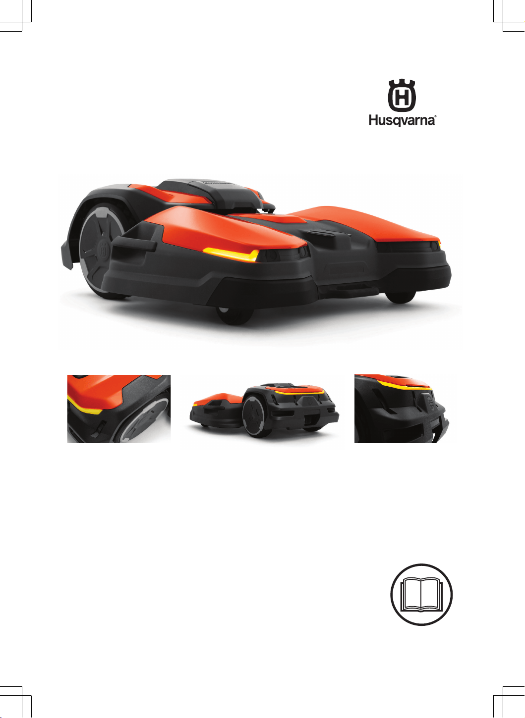
HUSQVARNA CEORA
™
Read the operator's manual carefully and make sure that you
understand the instructions before you use the product.

Contents
1 Safety
1.1 Safety definitions...................................................4
1.2 General safety instructions....................................4
1.3 Safety instructions for installation..........................5
1.4 Safety instructions for operation............................5
1.5 Safety instructions for maintenance...................... 5
1.6 Battery safety........................................................ 5
1.7 To lift and move the product..................................6
2 Introduction
2.1 Support..................................................................7
2.2 Product description............................................... 7
2.3 System description................................................7
2.4 System overview................................................... 8
2.5 Product overview drive unit, CEORA
™
544/546 EPOS............................................................ 9
2.6 Product overview cutting deck, CEORA
™
RZ 43L/43M................................................................ 9
2.7 Product overview charging station,
CEORA
™
CS4.......................................................... 10
2.8 Control panel overview........................................11
2.9 LED indicator on the product...............................11
2.10 Symbols on the product.................................... 12
2.11 Symbols on the battery..................................... 12
2.12 Symbols in the app............................................12
2.13 General manual instructions............................. 13
3 Installation
3.1 Introduction - Installation..................................... 14
3.2 Primary components for installation.................... 14
3.3 To prepare for installation................................... 14
3.4 To examine where to put the reference station...14
3.5 To examine where to put the charging station.... 14
3.6 To examine where to install the objects on
the map..................................................................... 16
3.7 Installation of the product.................................... 18
4 Settings
4.1 Schedule............................................................. 27
4.2 To use systematic mowing..................................27
4.3 Cutting height...................................................... 27
4.4 Pattern.................................................................27
4.5 Operation............................................................ 27
4.6 Accessories.........................................................28
4.7 General (Bluetooth
®
only)................................... 28
4.8 Security............................................................... 28
4.9 Automower
®
Connect (Bluetooth
®
only)............. 29
4.10 Messages..........................................................29
4.11 Mowing profiles................................................. 29
4.12 Download firmware over the air (Firmware
over the air FOTA).................................................... 29
5 Operation
5.1 To set the product to ON.....................................30
5.2 To start the product............................................. 30
5.3 To select operation mode....................................30
5.4 appDrive .............................................................30
5.5 Work area selection............................................ 30
5.6 Operation mode Park.......................................... 30
5.7 Operation mode Park at Maintenance point........31
5.8 To stop the product............................................. 31
5.9 To set the product to OFF................................... 31
5.10 To charge the battery........................................ 31
5.11 To release the wheel brakes and move
the product................................................................ 31
6 Maintenance
6.1 Introduction - maintenance..................................33
6.2 Maintenance schedule........................................ 33
6.3 To put the cutting deck in service position.......... 35
6.4 To put the cutting deck in cut position.................35
6.5 Clean the product................................................36
6.6 Replacement of the blades and blade discs....... 36
6.7 Adjustment of the wheel brushes........................ 38
6.8 Battery.................................................................38
7 Troubleshooting
7.1 Introduction - troubleshooting..............................39
7.2 Fault messages...................................................39
7.3 Information and warning messages.................... 46
7.4 LED indicator lamps on the charging station.......47
7.5 Symptoms........................................................... 47
8 Transportation, storage and disposal
8.1 Safety instructions for transportation...................50
8.2 To put the product into storage........................... 50
8.3 Transportation of batteries.................................. 50
8.4 Disposal.............................................................. 50
9 Technical data
9.1 Technical data.....................................................53
9.2 Registered trademarks........................................56
10 Declaration of Conformity
10.1 Original EU Declaration of Conformity.............. 57
10.2 Translated EU Declaration of Conformity..........58
2
1691 - 007 - 22.12.2023

1 Safety
1.1 Safety definitions
Warnings, cautions and notes are used to point out
specially important parts of the manual.
WARNING: Used if there is a risk of
injury or death for the operator or bystanders
if the instructions in the manual are not
obeyed.
CAUTION: Used if there is a risk of
damage to the product, other materials or
the adjacent area if the instructions in the
manual are not obeyed.
Note: Used to give more information that is necessary
in a given situation.
1.2 General safety instructions
WARNING: Read the warning
instructions that follow before you use the
product.
• Read the Operator’s manual carefully and make
sure you understand the instructions before you
use the product. Keep for future reference.
• This appliance is not intended for use by children
or persons with reduced physical, sensory or
mental capabilities (that could affect a safe
handling of the product), or lack of experience
and knowledge, unless they have been given
supervision or instruction concerning use of the
appliance by a person responsible for their safety.
• The product must only be used with the equipment
recommended Husqvarna. All other types of use
are incorrect.
• Do not use the product when persons, especially
children, or animals are in the work area.
• To prevent damage to the product and accidents to
vehicles and persons, do not install work areas and
transport paths across public pathways.
• Do not use the product in areas where persons are
not aware of the product.
• Warning signs must be put around the work area
of the product if it operates in public areas. The
signs must have the text that follows: Warning!
Automatic lawn mower! Keep away from the
machine! Supervise children!
• Do not run when you operate the product manually
with appDrive. Always walk, be sure on footing
on slopes and make sure to have balance at
all times. Always wear substantial footwear and
long trousers when you operate the product with
appDrive.
• Do not touch moving hazardous parts, such as the
blade disc, before it has come to a complete stop.
• Set the product to OFF before you clear a
blockage, do maintenance or examine the product,
and if the product starts to vibrate abnormally.
Examine the product for damage before you start
the product again. Do not use the product if it is
damaged.
• If an injury or accident occur get medical aid.
• Do not install the mains cable in an area where
the product cuts. Follow the instructions to install
the mains cable, refer to
Installation on page 14
.
Installation must be done by service personnel.
• Do not connect a damaged cable or plug, or touch
a damaged cable, before it is disconnected from
the power outlet. Disconnect the plug from the
power outlet if the cable becomes damaged while
in operation. A worn or damaged cable increases
the risk of electrical shock. A damaged cable must
be replaced by service personnel.
• When you connect the mains cable to the power
outlet, use a residual-current device (RCD) with a
tripping current of maximum 30 mA.
• Only charge the product in the included charging
station. For safe disposal of the battery, refer to
Disposal on page 50
. Incorrect use may result in
electric shock, overheating or leaking of corrosive
liquid from the battery. In the event of leakage of
electrolyte, flush with water/neutralizing agent. Get
medical aid if corrosive liquid comes in your eyes.
• Use only original batteries recommended by
Husqvarna. Product safety cannot be guaranteed
with other than original batteries. Do not use non-
rechargeable batteries.
• Follow the installation instructions that includes to
specify the work area and to attach the cutting
deck or other attachments, refer to
Installation on
page 14
.
• Follow the instructions about to start and operate
the product, refer to
Operation on page 30
.
• If there is a risk of thunderstorm, Husqvarna
recommends that the mains cable to the charging
station and the power supply unit to the reference
station are disconnected to decrease the risk of
damage to electrical components. Connect the
mains cable and the power supply again if there
is no longer a risk of thunderstorm.
• Follow the maintenance instructions and if
necessary use Husqvarna original spare parts,
refer to
Maintenance on page 33
.
4
- Safety 1691 - 007 - 22.12.2023
• For technical data such as weight, dimensions and
noise emission values, refer to
Technical data on
page 53
.
• The operator is responsible for accidents or
dangers that occurs to other persons or property.
• The product must only be operated, maintained
and repaired by persons that are fully conversant
with its special characteristics and safety
regulations.
• It is not permitted to change the initial design of the
product.
• Obey national regulations about electrical safety.
• Husqvarna does not guarantee full compatibility
between the product and other types of
wireless systems such as remote controls, radio
transmitters or equivalent.
• The built-in alarm is very loud. Be careful,
especially if the product is handled indoors.
• Operation, charging and storage temperature
is 0-45°C / 32-113 °F. Long-term storage
temperature that is more than 1 month, must be
0-25 °C / 32-77 °F.
1.3 Safety instructions for installation
WARNING: Read the warning
instructions that follow before you use the
product.
• Do not install the charging station in an area where
there is a risk that persons trip on it.
• Do not install the charging station, including any
accessory, at a location that is below, or within 60
cm / 24 in. from, any combustible material. In case
of malfunction, heating of the charging station and
the power supply may occur and create a potential
risk of fire.
• Install the charging station out of reach of pests
such as ants.
• Applicable to USA/Canada. If power supply is
installed outdoors: Risk of Electric Shock. Install
only to a covered Class A GFCI receptacle (RCD)
that has an enclosure that is weatherproof with the
attachment plug cap inserted or removed.
• Do not install the charging station where there is a
risk of standing water.
1.4 Safety instructions for operation
WARNING:
Read the warning
instructions that follow before you use the
product.
• Keep your hands and feet away from the rotating
blades. Do not put your hands or feet near or
below the product when it is set to ON.
• Use the park mode or set the product to OFF when
persons, especially children or animals are in the
work area. Refer to
To set the product to OFF
on page 31
. Husqvarna recommends to set the
product to operate when the work area has no
activity. The product can cause injury to animals at
night in work area, for example hedgehogs. Refer
to
Scheduled operation on page 30
.
• Make sure that there are no objects such as
stones, branches, tools or toys on the lawn. The
blades can be damaged if it hits an object.
• Do not lift the product or move it when it is set to
ON.
• Do not to let the product collide with persons or
animals. If a person or animal comes in the way of
the product, stop the product immediately. Refer to
To stop the product on page 31
.
• Do not put objects on top of the product, the
charging station or the reference station.
• Do not use the product if the STOP button does
not work.
• Always set the product to OFF when it is not in
operation. The product can only start when you
enter the correct PIN code.
• Do not use the product at the same time as a
pop-up sprinkler. Use the
Schedule
function so the
product and pop-up sprinkler do not operate at the
same time. Refer to
Scheduled operation on page
30
.
• Do not put a transport path where pop-up
sprinklers are installed.
• Do not let the product operate when there is
standing water in the work area. For example when
heavy rain forms pools of water.
1.5 Safety instructions for maintenance
WARNING:
Read the warning
instructions that follow before you do
maintenance on the product.
• Set the product to OFF when you do maintenance
on the product.
• Do not use a high-pressure washer to clean the
product. Do not use solvents to clean the product.
• Disconnect the plug to the charging station before
you clean or do maintenance of the charging
station.
1.6 Battery safety
WARNING:
Read the warning
instructions that follow before you use the
product.
1691 - 007 - 22.12.2023 Safety - 5
• Lithium-ion batteries can explode or cause fire if
disassembled, short-circuited, exposed to water,
fire, or high temperatures. Handle carefully, do
not dismantle, open the battery or use any type
of electrical/mechanical abuse. Avoid storage in
direct sunlight.
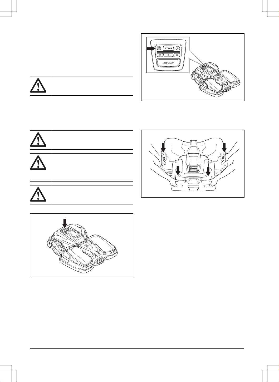
1.7 To lift and move the product
WARNING: The product must be set to
OFF before you lift the product.
• To safely move the product from or in the work
area, lift it manually or operate it with appDrive.
Refer to
To lift the product manually on page 6
and
appDrive on page 30
.
1.7.1 To lift the product manually
WARNING: Two persons are
necessary to lift the product.
CAUTION: Do not lift the product when
it is parked in the charging station. It can
cause damage to the charging station and/or
the product.
CAUTION: Do not lift the product by the
front handle.
1. Push the STOP button to stop the product.
2. Set the product to OFF. Refer to
To set the product
to OFF on page 31
.
3. Pull the product out of the charging station before
you lift the product.
4. Lift the product by the handles on the sides of the
cutting deck and the handles on the rear part of the
drive unit.
6 - Safety 1691 - 007 - 22.12.2023
2 Introduction
Serial number:
PIN code:
The serial number is on the product rating plate and on the product carton.
2.1 Support
For support about the product, speak to your Husqvarna
servicing dealer.
2.2 Product description
Note: Husqvarna regularly updates the appearance
and function of the products. Refer to
Support on page
7
.
The product is a robotic lawn mower that contains a
drive unit and a cutting deck. The product has a battery
power source and operates automatically. The product
operates until the battery state of charge is low or until
the work area is cut, then the product starts to go to the
charging station. The movement pattern of the product is
systematic to satisfactorily cut large areas.
The work area in which the product operates is specified
by the virtual boundary. The satellite receiver in the
product senses when it goes near the virtual boundary.
2.3 System description
The system contains a CEORA
™
robotic lawn mower,
a charging station and a reference station. The robotic
lawn mower and reference station uses the EPOS
(Exact Positioning Operating System) technology with
satellite signals to position the robotic lawn mower
correctly, this means that boundary wires are not
necessary. The reference station is stationary and sends
correction data to the robotic lawn mower to get an
accurate position of the robotic lawn mower. The virtual
work area for the product is made in the Husqvarna
Fleet Services
™
app. The product is operated and
waypoints are added to make a map in the app. The
reference station can operate as a repeater to make
a network of reference stations. You can use the
repeaters on larger areas. Refer to
System overview on
page 8
.
2.3.1 Connectivity
Husqvarna Fleet Services
™
is a cloud solution
that is available as an app and on the web on
www.husqvarna.com. You can add all your products
to Husqvarna Fleet Services
™
to get an overview
and control the products. Refer to
Husqvarna Fleet
Services
™
on page 21
.
Automower
®
Connect is an app that you can use to
install the product and to select the operation settings
of the product. Refer to
Automower
®
Connect on page
21
.
1691 - 007 - 22.12.2023
Introduction - 7
2.4 System overview
3
13
1
10
11
6
9
12
4
2
8
8
8
7
2
5
1. Satellites
2. Satellite signals
3. Reference station
1
4. Correction data
5. Charging station
6. Virtual boundary
7. Stay-out zone
8. Work area
9. Mobile device
2
10. Docking point
11. Transport path
12. Robotic lawn mower
13. Maintenance point
1
Not included.
2
Not included.
8 - Introduction 1691 - 007 - 22.12.2023
2.5 Product overview drive unit, CEORA
™
544/546 EPOS
1
2
3
6
7
8
9
4
5
10
11
1. Drive unit (DU)
2. Rating plate drive unit
3. Hatch
4. Drive unit body
5. USB outlet for service tool
6. Control panel
7. Drive wheels
8. Rear bumper
9. Rear handles
10. Rear safety lights
11. Active wheel brush kit
3
2.6 Product overview cutting deck, CEORA
™
RZ 43L/43M
12
10
16
4
3
5
2
7
13
15
11
6
14
1
9
8
3
Is included for some markets and models or is available as accessory.
1691 - 007 - 22.12.2023 Introduction - 9
1. Cutting deck (CD)
2. Lever
3. Shaft
4. Rating plate of the cutting deck
4
5. Combi tool
5
6. Cutting deck body
7. Front safety lights
8. Charging plates
9. Ultrasonic sensors
10. Center top cover
11. Side handles
12. Front handle
13. Front wheels
14. Blade disc, blades, skid plate
15. Service wheels
16. Blades and screws
2.7 Product overview charging station, CEORA
™
CS4
2
5
9
4
3
6
7
10
8
1
1. Rating plate of the charging station
2. LED indicators of the charging station
3. Contact plates
4. Baseplates
5. Mains cable
6
6. Screws to attach the charging station
7. Coupling
8. Support plates
9. Support plate for soft surface
7
10. Hex key
4
Found below the top cover.
5
Found below the center top cover.
6
The appearance can be different for different markets.
7
Is available as accessory.
10 - Introduction 1691 - 007 - 22.12.2023
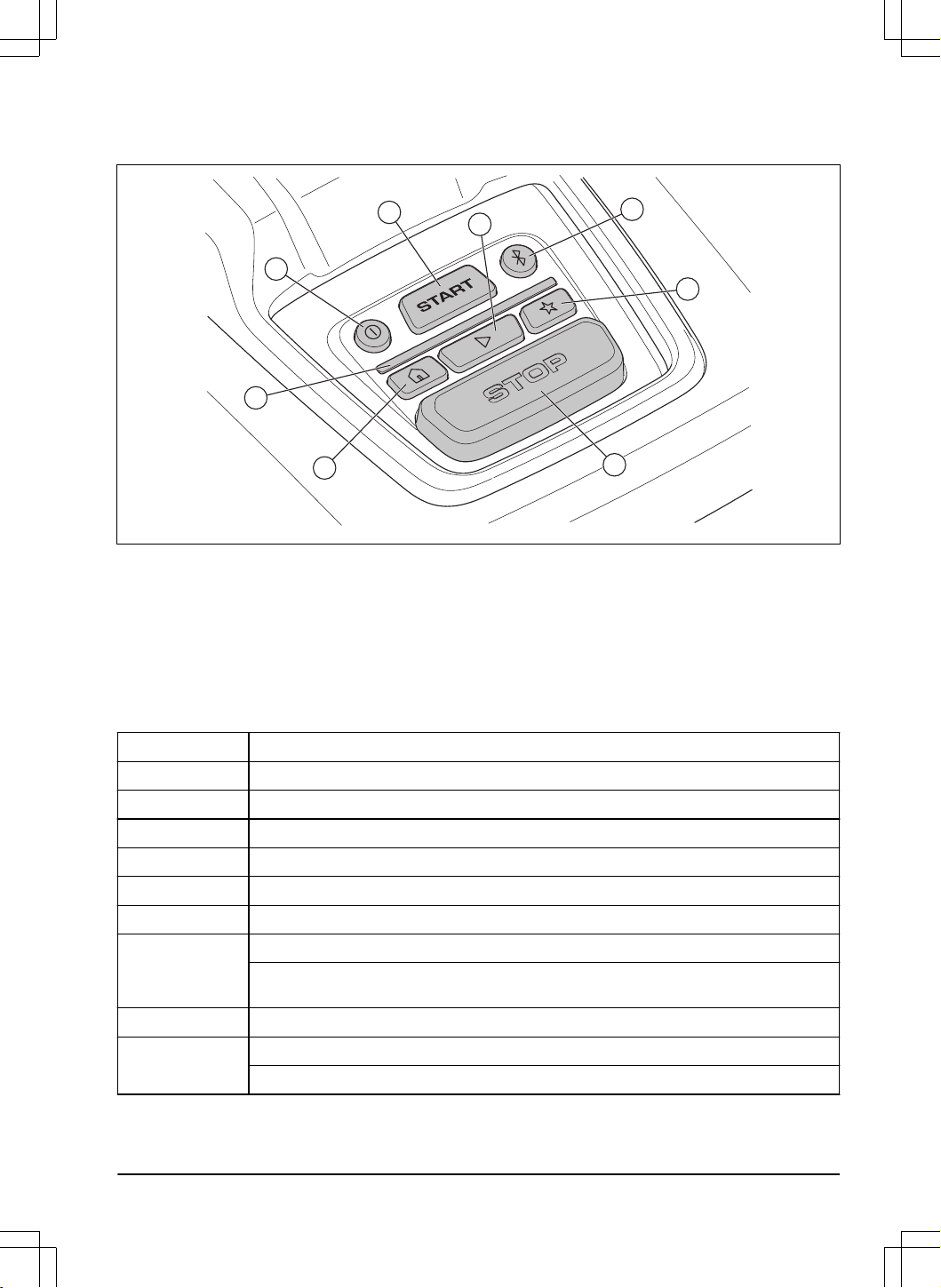
2.8 Control panel overview
1
5
8
6
2
3
4
7
1. ON/OFF button
2. START button
3. Bluetooth
®
button
4. LED indicator
5. Park button
6. Play button
7. Maintenance point button
8. STOP button
2.9 LED indicator on the product
The LED indicator on the control panel of the product shows the current product status:
LED indicator light Product status
Constant green The product cuts the lawn or moves out of the charging station.
Pulsates green The product is preparing to start its operation.
Flashes green The product is in
Pause
mode.
Flashes red The product stopped because of an error.
Constant yellow The STOP button was pushed.
Flashes yellow The PIN code must be entered to start the product.
Constant blue The product moves to the charging station or a maintenance point.
An app is connected to the product with Bluetooth
®
, the LED indicator is constant blue for 3
seconds.
Pulsates blue The product charges in the charging station.
Flashes blue The product is parked in charging station.
Bluetooth
®
is enabled and you can connect to the product with Bluetooth
®
.
1691 - 007 - 22.12.2023 Introduction - 11
LED indicator light Product status
Constant white The product is in appDrive mode.
Pulsates white The product sets to OFF.
Firmware installation is in progress.
Flashes white New firmware must be installed.
There is more information on www.husqvarna.com. Speak to your approved servicing dealer for more information.
2.10 Symbols on the product
These symbols can be found on the product. Make sure
that you understand them.
WARNING: Read the opera-
tor instructions before you op-
erate the product.
WARNING: Disable the prod-
uct before maintenance or
before you lift the product.
WARNING: Keep a safe dis-
tance from the product when
it is in operation. Keep your
hands and feet away from the
rotating blades of the product.
WARNING: Do not sit on
the product. Do not put your
hands or feet near or below
the product.
Use a detachable power sup-
ply as specified on the rating
plate adjacent to the symbol.
This product complies with the applicable
EU Directives.
This product complies with the applicable
UK Directives.
It is not permitted to dispose the product
as usual domestic waste. Obey national
regulations and use the local recycling
system.
The chassis contains components which
are sensitive to electrostatic discharge
(ESD). The chassis must only be opened
and sealed by an authorized service
technician. The warranty will not be
applicable if the seal is broken.
Note: Other symbols/decals on the product refer to
certification requirements for some markets.
2.11 Symbols on the battery
WARNING: Lithium-ion batteries can
explode or cause fire if disassembled,
short-circuited or handled roughly. Do not
expose to water, fire or high temperature.
Read the user instructions.
Do not discard the battery into fire and do
not expose the battery to a heat source.
Do not immerse the battery into water.
2.12 Symbols in the app
Shows the strength of the radio signal that
the product receives from the reference
station.
The status is
EPOS confirmed
. The
product has an accurate position and
direction. This is necessary to operate
the product automatically and for the
installation of map objects.
12 - Introduction 1691 - 007 - 22.12.2023

The status is
EPOS action is necessary
.
The product has an accurate position but
it is necessary to operate the product,
manually or automatically, to get an
accurate direction.
The status is
EPOS searching
. The
product does not have an accurate
position and is searching for the satellite
signals and the correction data to get an
accurate position.
2.13 General manual instructions
The following system is used in the Operator’s Manual
to make it easier to use:
• Text written in
italics
is a text that is in
the Automower
®
Connect app, Husqvarna Fleet
Services
™
app or is a reference to another section
in the Operator’s manual.
• Text written in bold is one of the buttons on the
product or in appDrive.
1691 - 007 - 22.12.2023 Introduction - 13
3 Installation
3.1 Introduction - Installation
WARNING: Read and understand the
safety chapter before you install the product.
CAUTION: Use original spare parts and
installation material.
Note: Refer to www.husqvarna.com for more
information about installation.
3.2 Primary components for installation
The installation includes the components that follow:
• Robotic lawn mower that cuts the lawn
automatically. It includes a cutting deck and a drive
unit.
• Charging station, that charges the product. It
includes a power supply, which is connected to an
100-240V power outlet.
• Reference station
8
, that receives satellite signals
and sends correction data to the robotic lawn
mower.
• Mobile device
9
with the Husqvarna Fleet
Services
™
and the Automower
®
Connect app to
do the installation and the settings for the product.
3.3 To prepare for installation
CAUTION: Holes with water in the lawn
can cause damage to the product.
CAUTION: Read the installation
chapter before you start the installation.
• Make a blueprint of the work area and include all
obstacles. This makes it easier to examine where
to put the charging station, the reference station,
and the virtual boundaries.
• Make a mark on the blueprint where to put
the charging station, the reference station, the
maintenance point, the transport paths and the
virtual boundaries for the work areas and stay-out
zones.
• Follow the instructions for distances between
obscuring objects.
• Make the ground in the lawn flat. Make sure that
there are no holes or bulges in the lawn.
• Cut the grass before you install the product. Make
sure that the grass is maximum 5 cm / 2 in.
Note: The first weeks after installation the sound level
when the product cuts the grass can be higher than
usual. The sound level decreases after some time.
3.4 To examine where to put the
reference station
Read and understand the instructions about where to
put the reference station. Refer to the Operator's manual
for the reference station.
3.5 To examine where to put the
charging station
• You can put the charging station in the work
area or not in the work area. No transport path
is necessary if the charging station is put in the
work area (A). No transport path is necessary if
the product is fully in the work area when it is at
the charging station docking point. If the charging
station and docking point (B) are not in the work
area, you must install a transport path (C).
A
B
C
• Put the charging station (A) where the docking
point (B) has unimpeded sky view. The charging
station docking point (B) is where the product
stops after reversing from the charging station.
The reversing distance can be set to 130-220
cm / 51-87 in. Husqvarna recommends to have a
minimum of 6 m / 19.6 ft. (C) free space in front of
the charging station.
8
Not included.
9
Not included.
14 - Installation 1691 - 007 - 22.12.2023
B
C
A
AB
C
Note: Short reversing distance decreases the
risk of track marks. A long reversing distance can
be necessary to have good satellite signals at the
docking point.
• If the product must not operate in a part of the
docking area, put a protective wall that is minimum
15 cm / 6 in. in height. The docking area is a
circular area around the charging station with a
radius (A) of 3 m / 9.8 ft.
A
Note:
The product uses the charging station
signal to find the charging station when it is in the
docking area.
• Put the charging station near a power outlet.
• Examine how to install the mains cable safely.
• Put the charging station on a flat surface, not on
gravel.
• Husqvarna recommends to install the charging
station on a hard surface, such as concrete or
equivalent. To install the charging station on a soft
surface, use the support plate accessory.
• Put the charging station on a level surface.
max. 5 cm / 2"
max. 5 cm / 2"
Max +/- 4 cm / 1.6 In.
• The baseplate of the charging station must not be
bent.
1691 - 007 - 22.12.2023
Installation - 15
• Put the charging station in an area with good
airflow.
• Put the charging station in an area with protection
from the sun.
• Use a residual-current device (RCD) with a tripping
current of maximum 30 mA when you connect the
mains cable to the power outlet.
CAUTION: Do not install the charging
station where there are metal objects
in the ground. Metal objects can cause
interference with the charging station signal.
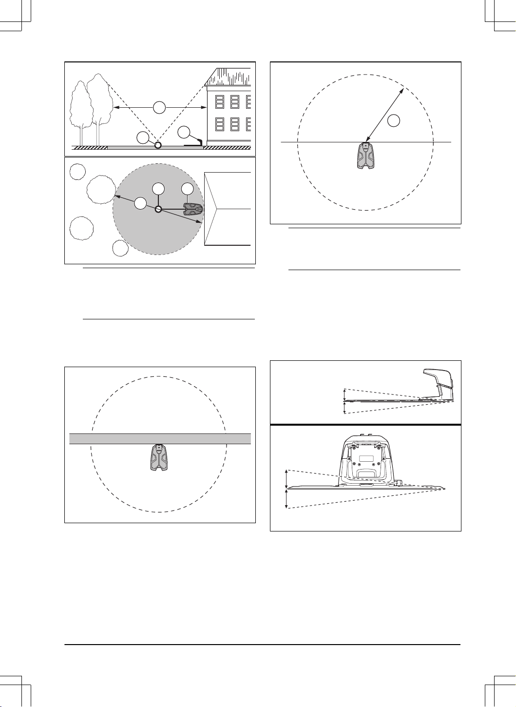
3.6 To examine where to install the
objects on the map
CAUTION: If the work area is adjacent
to water bodies, slopes, precipices or a
public road, the virtual boundary must have
a protective wall. The wall must be minimum
15 cm / 6 in. in height.
CAUTION: Do not let the product
operate on gravel.
CAUTION: For careful operation
without noise, isolate all obstacles such as
trees, roots and stones.
Note: Make a blueprint of the work area before you
install the virtual boundaries.
• Make sure that the product can receive radio
signals from the reference station in all parts of the
work area.
Note:
The maximum distance decreases if there
are objects between the reference station and
product.
• Husqvarna recommends a maximum distance from
the charging station to the most remote part of
the installation. The maximum distance is 1000 m /
3280 ft.
Note:
The maximum distance decreases if there
are slopes and high grass.
3.6.1 To install map objects near buildings
and trees
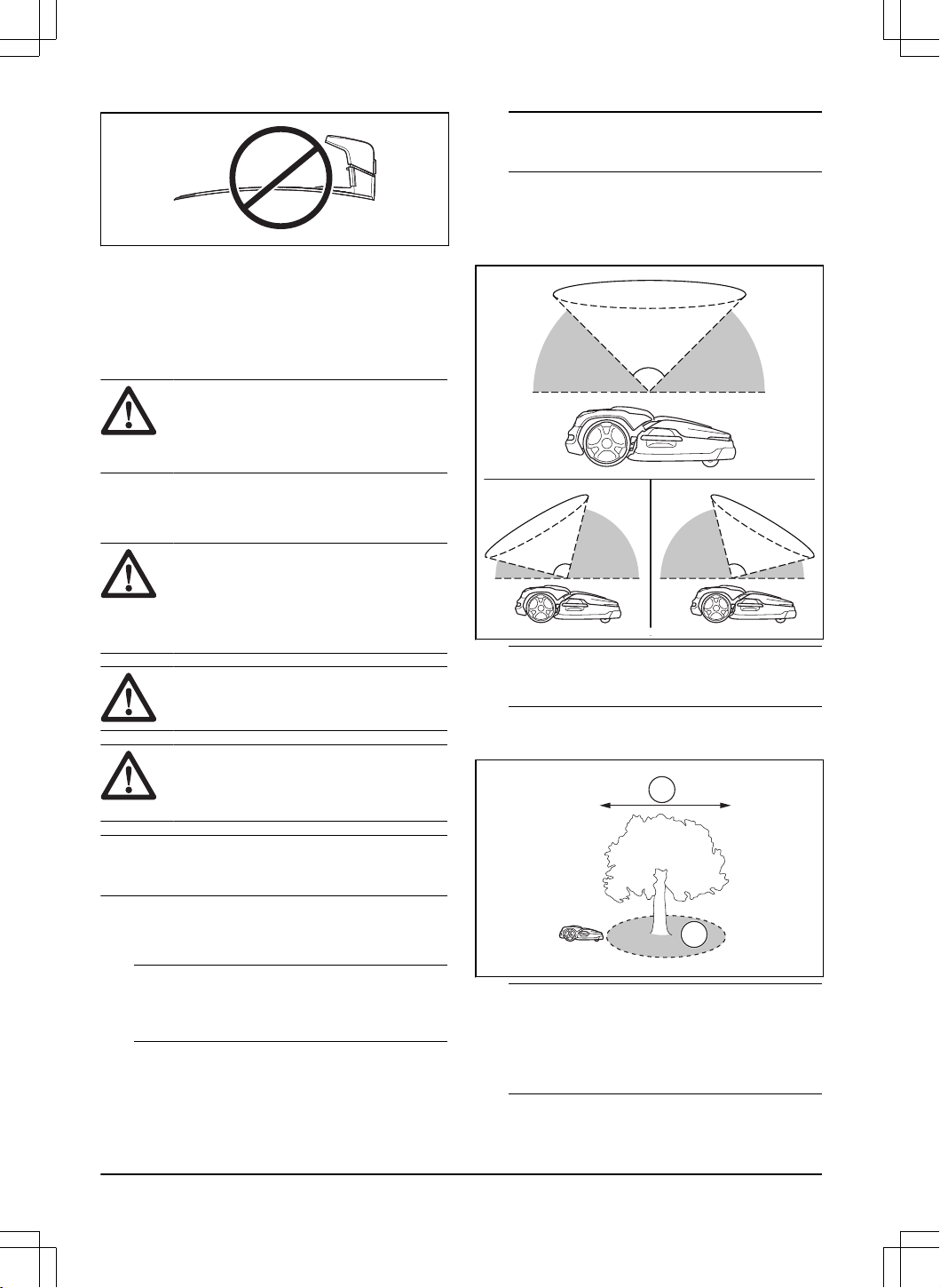
• Make sure that 90° section of the sky is
unimpeded.
90°
Note: The product cannot receive signals from
the satellite for navigation if the sky is impeded.
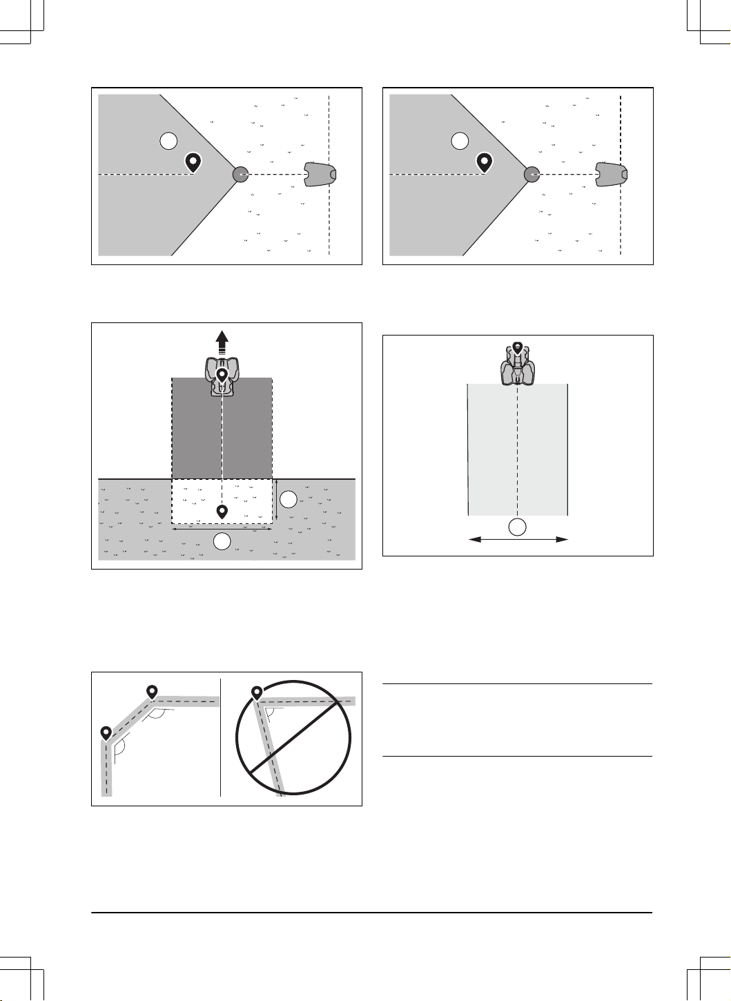
• Make a stay-out zone (B) around trees or a group
of trees with tree canopies that are more than 4 m /
13 ft. in diameter (A).
B
A
Note:
Trees or a group of trees with tree
canopies that are more than 4 m / 13 ft. in diameter
(A) can cause temporary stops for the product.
Smaller trees do usually not cause interference
with the operation of the product.
16 - Installation 1691 - 007 - 22.12.2023
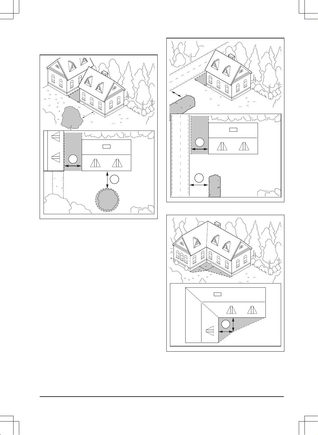
• Make sure that the areas between buildings or
trees have a distance (C) of minimum 4 m / 13.1
ft.
C
C
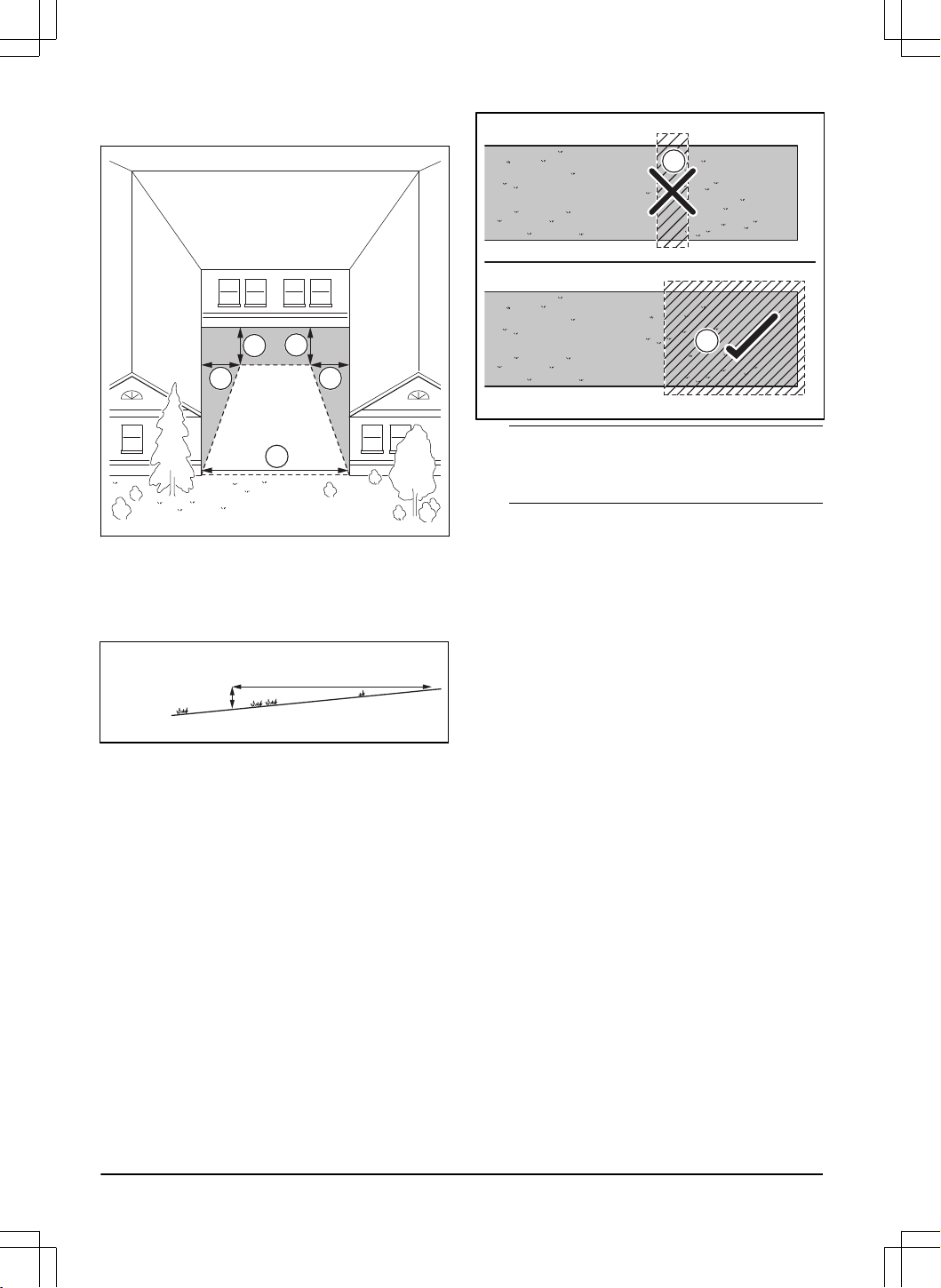
• Make sure that a passage between 2 low objects
or between 1 low object and 1 high object has a
minimum width (D) of 3 m / 9.8 ft.
D
D
• For L-shaped buildings, install the virtual boundary
at a minimum distance (E) of 1.5 m / 5 ft. from it.
E
• To install virtual boundaries in an area with an U-
shaped building, make sure that the distance (G) is
minimum 6 m / 20 ft. If the building is higher than 3
m / 10 ft., make sure that the distance (G) is twice
the height of the highest building. Install the virtual
1691 - 007 - 22.12.2023
Installation - 17
boundary at a minimum distance (F) of 1.5 m / 5 ft.
from the building.
F
F
F
F
G
3.6.2 To install the map objects in a slope
The product can operate in 20% slopes. Virtual
boundaries can be installed in maximum 15% slopes.
The slope (%) is calculated as height for each m.
Example: 10 cm / 100 cm = 10%.
10 cm/ 4"
100 cm/ 40"
10%
• For slopes more than 20% in the work area, isolate
the slope with a stay-out zone.
• For slopes adjacent to a public road, put a fence
or a protective wall of minimum 15 cm / 6 in. along
the outer edge of the slope.
• Husqvarna recommends to set the direction of the
systematic pattern straight up the slope to prevent
wear on the grass.
• Install the virtual boundaries in slopes that are
maximum 15%.
3.6.3 To examine where to make stay-out
zones
• Make stay-out zones around objects that are larger
than 2x2 m / 6.6x6.6 ft.
• Make sure that the stay-out zone includes the
complete area were the product must not operate
(B).
B
A
Note:
Do not make a stay-out zone across the
work area to prevent the product to enter parts of
the work area (A).
• Make sure that the stay-out zone is minimum
30x30 cm / 1x1 ft.
3.7 Installation of the product
3.7.1 To install the product
Do the general steps that follow to install the product:
1. Attach the cutting deck to the drive unit. Refer to
To attach the cutting deck on page 19
.
2. Install the charging station. Refer to
Installation of
the charging station on page 20
.
3. Install the reference station. Refer to the
Operator's manual for the reference station.
4. Install the Husqvarna Fleet Services
™
app and the
Automower
®
Connect app on your mobile device.
Refer to
Husqvarna Fleet Services
™
on page 21
.
5. Do a pairing operation of the product and the
Husqvarna Fleet Services
™
app. Do the basic
settings in the start up sequence in app. Refer to
Husqvarna Fleet Services
™
on page 21
.
6. Make a map with work areas, stay-out zones,
transport paths and maintenance points. Refer to
Installation of the map objects on page 21
.
7. Use Husqvarna Fleet Services
™
app to do settings
for the product. Refer to
Settings on page 27
.
3.7.2 Installation tools
• 19 mm open end socket wrench.
• Hex key, 8 mm. Included with the charging station.
• Combi tool. Included with the cutting deck.
• 10 mm socket wrench.
• Drilling machine, 6 mm drill.
• Ratchet wrench or torque wrench, 10mm.
18
- Installation 1691 - 007 - 22.12.2023
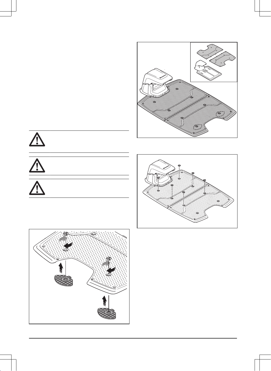
3.7.3 To attach the cutting deck
1. Set the drive unit to OFF. Refer to
To set the
product to OFF on page 31
.
2. Put the cutting deck in front of the drive unit.
3. Open the hatch on the drive unit.
4. Remove the center top cover on the cutting deck.
5. Put the frame on the drive unit above the cutting
deck and the cable.
6. Align the shaft with the hole in the drive unit.
7. Align the shaft with the hole in the frame.
8. Install the screw with the ratchet wrench or torque
wrench, 10 mm. Tightening torque 5 Nm.
9. Tighten the nut on the other side with a 19 mm
open end socket wrench. Tightening torque 9 Nm.
10. Connect the cable to the drive unit. Make sure that
the connection is aligned correctly.
11. Tighten the inner part of the connector clockwise.
12. Lift the rear part of the cutting deck and tilt the
lever.
13. Install the center top cover on the cutting deck.
14. Close the hatch.
1691 - 007 - 22.12.2023
Installation - 19
3.7.4 To remove the cutting deck
1. Set the drive unit to OFF. Refer to
To set the
product to OFF on page 31
.
2. Open the hatch on the drive unit.
3. Remove the center top cover on the cutting deck.
4. Loosen the inner part of the connector
counterclockwise and disconnect the cable.
5. Tilt the lever.
6. Loosen the nut with the 19 mm open end socket
wrench and remove the screw with the Combi tool.
7. Remove the cutting deck from the drive unit. Put
the covers on the 2 connectors.
3.7.5 Installation of the charging station
Read and understand the instructions about the
charging station. Refer to
To examine where to put the
charging station on page 14
.
WARNING: Read and understand the
safety instructions for installation. Refer to
Safety on page 4
.
CAUTION: Do not make new holes in
the charging station plate.
CAUTION: Do not put your feet on the
baseplate of the charging station.
3.7.5.1 To install the charging station
1. Put the charging station in the selected area.
2. Put the 2 support plates on the rear side of the
top baseplate. Use an 8 mm hex key to attach the
support plates from the front side with 2 couplings.
3. Put the 2 top baseplates on top of the lower
baseplate.
4. Attach the top baseplates to the lower baseplate
with 6 couplings. Use a 8 mm hex key to attach the
couplings.
5. Drill 14 holes in the ground with a 6 mm drill.
6. Attach the charging station to the ground with the
14 supplied screws. Use a 10 mm socket wrench
to attach the screws.
20
- Installation 1691 - 007 - 22.12.2023
CAUTION: Do not tighten the
screws too much.
7. Connect the mains cable to a 100-240V power
outlet.
8. Put the product in the charging station. Push the
ON/OFF button on the product for 3 seconds to
charge the product. Refer to
To charge the battery
on page 31
.
3.7.5.2 To do a visual check of the charging station
1. Make sure that the LED indicator lamps on the
charging station have a green light.
2. If the LED indicator lamps do not have a green
light, do a check of the installation. Refer to
LED
indicator lamps on the charging station on page
47
and
To install the charging station on page 20
.
3.7.6 Installation of the reference station
Install the reference station according to the instructions
in the Operator's manual for the reference station.
3.7.7 Husqvarna Fleet Services
™
Husqvarna Fleet Services
™
is a cloud solution that
gives the commercial fleet manager an overview of
all products. It also gives the fleet manager the
possibility to control all products remotely. Husqvarna
Fleet Services
™
is available as a web service and as an
app. When you use the Husqvarna Fleet Services
™
app
you will be redirected to the Automower
®
Connect app.
For more information about Husqvarna Fleet Services
™
,
refer to www.husqvarna.com.
Note: All countries do not support cellular connection
because of regional specified cellular systems. The
included lifetime service only applies if there is a third
part sub-supplier of 2G/4G available in the operational
area.
3.7.8 Automower
®
Connect
Automower
®
Connect is a free app for your mobile
device. Use the app for installation, settings and
operation of your product. You can also find more
information for example about alarm and statistics in the
Automower
®
Connect app.
The app gives 2 modes of connectivity: Long-
range cellular connectivity and Short-range Bluetooth
®
connectivity.
3.7.9 To do the basic settings
When the product is set to ON for the first time, there
are some basic settings to do before the product can
start to operate.
1. Download the Husqvarna Fleet Services
™
app and
Automower
®
Connect app to your mobile device.
2. Log on to the Husqvarna Fleet Services
™
app.
3. Set the product to ON.
4. Start Bluetooth
®
on your mobile device.
Note:
The Bluetooth
®
pairing operation mode
of the product is enabled for 3 minutes. If the
pairing operation between the product and the
mobile device is not completed correctly, push
the Bluetooth
®
button on the product to enable
Bluetooth
®
again.
Note: Other devices with Bluetooth
®
enabled
can cause interference with the pairing operation.
Disable Bluetooth
®
on the other devices if it
causes interference with the pairing operation.
5. Select
Add robotic mower
in the app to add your
product and follow the instructions in the app.
6. Do a pairing operation of the product and the
reference station.
7. Do a pairing operation of the product and the
charging station. Select to enable GeoFence or not
and set the reversing distance.
3.7.10 Installation of the map objects
Read and understand the instructions about where to
install the map objects. Refer to
To examine where to
install the objects on the map on page 16
.
1691 - 007 - 22.12.2023
Installation - 21
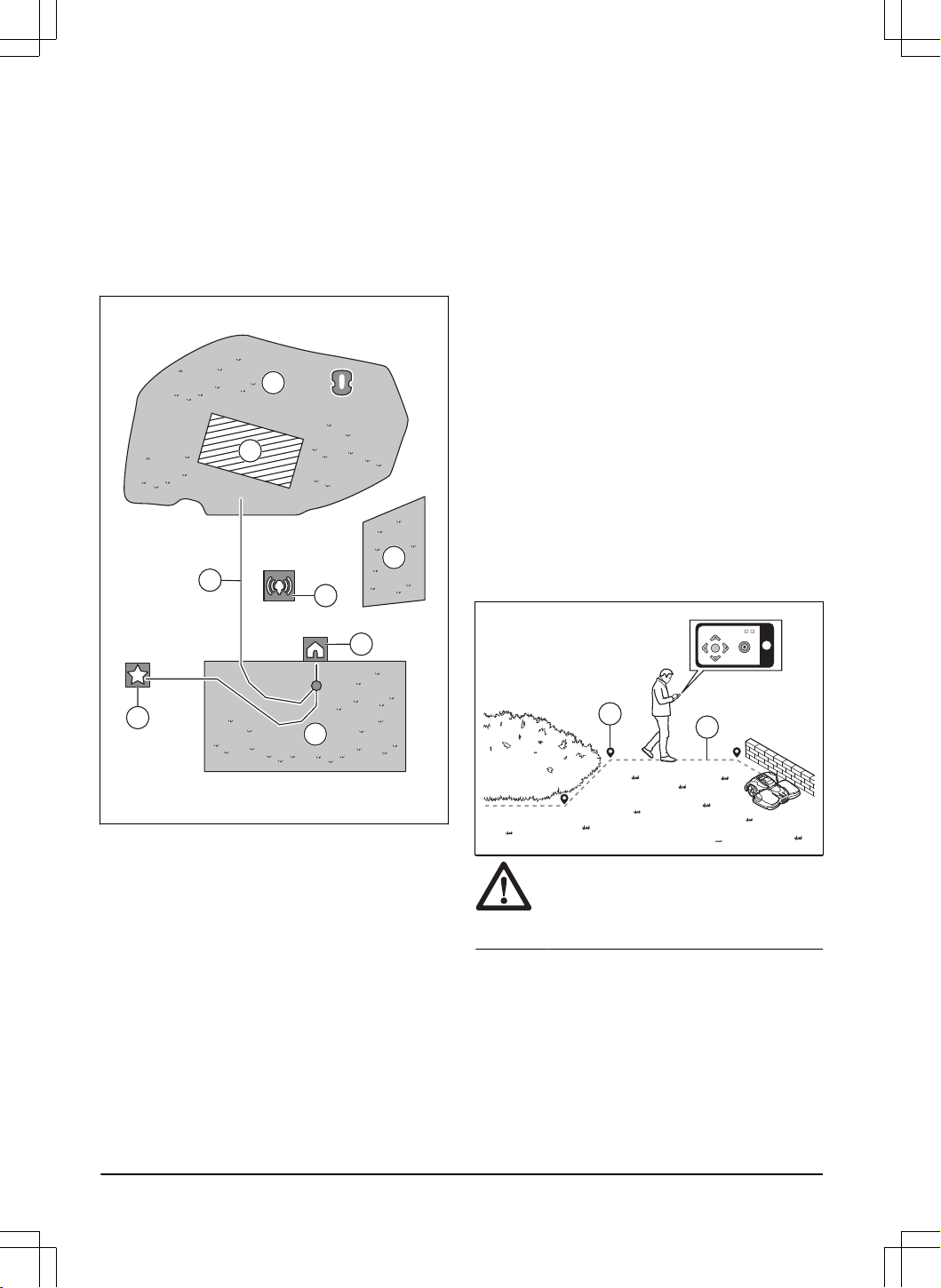
On the map you can install the objects that follow in the
app:
•
Work areas
(A)
•
Stay-out zones
(B)
•
Transport path
(C)
•
Charging station
(D)
•
Maintenance point
(E)
•
Reference station
(F)
•
Work area (Secondary area)
(G)
A
G
B
A
D
E
C
F
For a complete map installation, you must install a work
area and a charging station on the map.
A work area is specified by virtual boundaries. Maximum
20 work areas and secondary areas can be installed on
a map.
There are two types of work areas:
• A work area that has a charging station in it or
connected to it with a transport path where the
product operates automatically.
• A secondary area is a work area with no charging
station and no transport path. The product must be
moved manually to and from the work area.
A transport path is a specified path between the docking
point in front of the charging station and a work area.
The product can operate automatically in this path, but
does not cut grass. A transport path can temporarily be
enabled and disabled in the app.
Stay-out zones can be made if there are areas where
the product must not operate. A stay-out zone is
specified by virtual boundaries. Stay-out zones can
temporarily be enabled and disabled in the app.
A maintenance point is a specified position where the
product can be parked at. This can for example be used
for a service point where maintenance of the product
is done. The maintenance point is connected to the
docking point with a path.
To install objects on the map, operate the product with
the appDrive installation to add waypoints on the map.
Refer to
To install objects on the map on page 22
.
3.7.10.1 To install objects on the map
The waypoints (A) are positions that makes the virtual
boundaries and paths (B). The lines are straight
between the waypoints. It is recommended to use as
few waypoints as possible. For each work area and
the related stay-out zones and transport path the total
maximum number of waypoints are 800. Husqvarna
recommends to add maximum 1000 waypoints for the
complete installation of the map. To make smooth
curves use several waypoints. Husqvarna recommends
to set the minimum distance of 30 cm / 1 ft. between the
waypoints. You can adjust the positions of the waypoints
in the app after the installation of the map.
B
A
CAUTION: Do not lift and move the
product between the waypoints when you
install the map objects. Use appDrive for a
correct installation.
22 - Installation 1691 - 007 - 22.12.2023
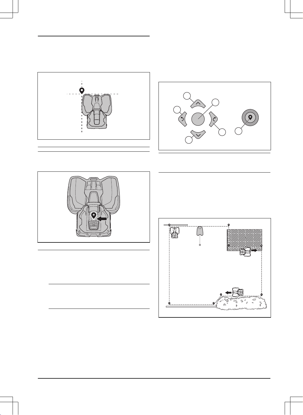
Note: The position of the waypoint when you install
a work area or a stay-out zone is in the front left
corner of the product. The virtual boundaries specifies
the area where the product operates. The product does
not cut the grass that is adjacent to the virtual boundary
because of the position of the cutting disc.
Note: The position of the waypoint when you install a
transport path or a path to a maintenance point is in the
middle of the product between the drive wheels.
• Make sure that you are near the product and
connected to the product with the app with
Bluetooth
®
.
• Make sure that the status is
EPOS confirmed
in the
appDrive.
Note:
A game controller with Bluetooth
®
can
be used together with appDrive to operate the
product.
• Make sure that the radio signal strength from
the reference station is good. The symbol for the
strength of the radio signal must be fully filled.
• Select the object you want to install and use the
buttons in the appDrive installation to operate the
product.
• Use the up button (A) to move the product forward.
• Use the down button (B) to move the product
rearward.
• Use the left
arrow button (C) to rotate the product
to the left.
• Use the right arrow button (D) to rotate the product
to the right.
• Use the center button (E) as a joystick to move and
rotate the product in any direction.
• Use the waypoint button (F) to add a waypoint in
the map.
A
D
F
B
C
E
Note: Walk 2-3 m / 6.5-9.8 ft. behind the product
when you operate the product with appDrive.
To make a work area
Minimum 3 waypoints are necessary to make a work
area.
• Operate the product clockwise around the
boundary of the work area.
• Add waypoints on the map. Add the waypoints
minimum 3 cm / 1 in. from obstacles.
• Add a waypoint to make the product cut the grass
at the edge between the lawn and the stone path.
Make sure that you straddel the edge of the lawn
and the stone path when you add a waypoint. The
product can straddel the edge if the height of the
stone path is maximum 1 cm / 0.4 in. in relation to
the lawn.
1691 - 007 - 22.12.2023
Installation - 23
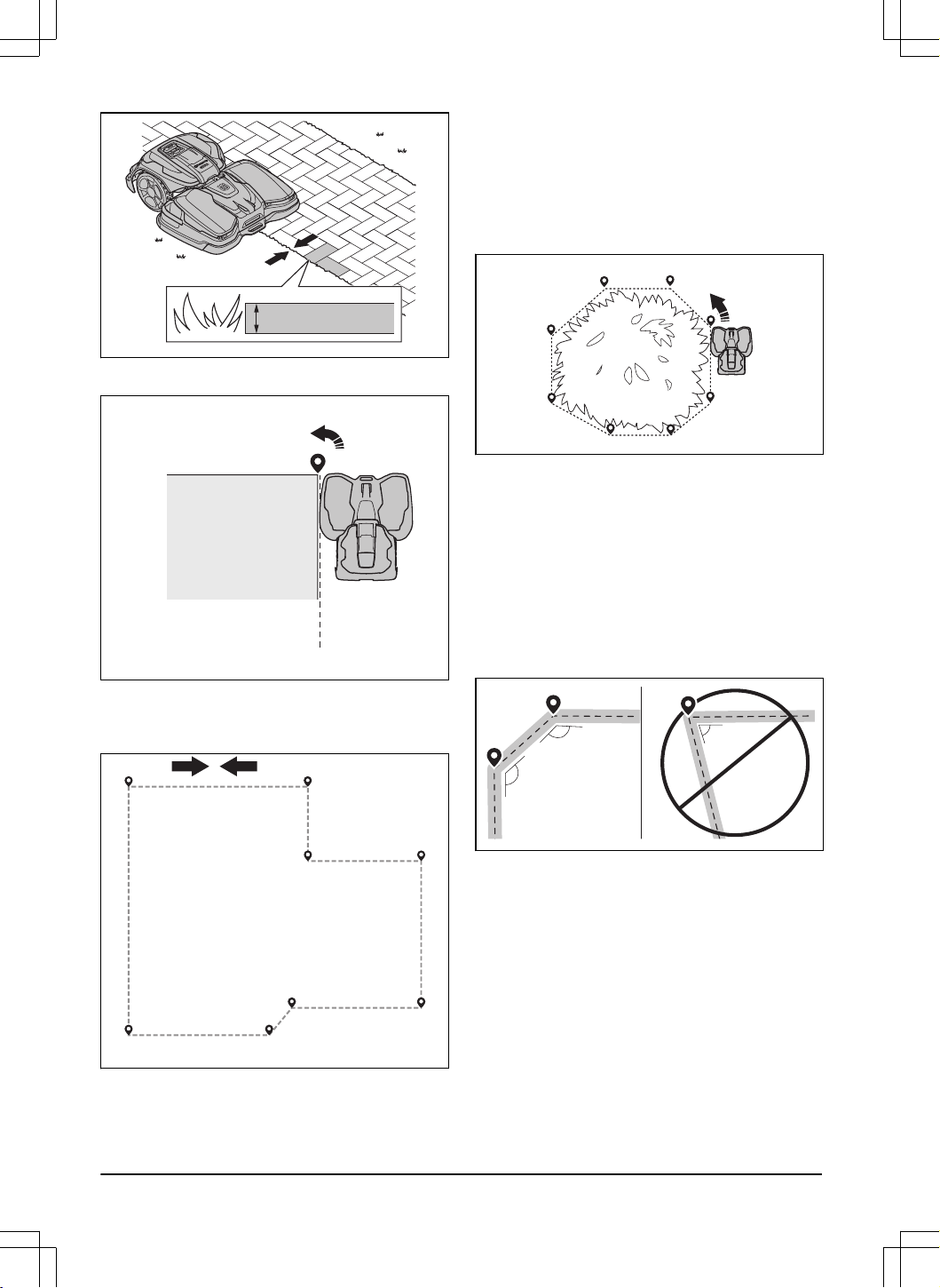
•
max 1 cm / 0.4”
• Add the waypoint at the outer corner to install the
virtual boundary around a corner.
• Do not set waypoints that make a virtual boundary
go across itself in the same work area.
• Save the work area to automatically connect the
first and last waypoint with a virtual boundary.
1
2
3
4
5
6
7
8
To make a stay-out zone
Minimum 3 waypoints are necessary to make a stay-out
zone.
• Operate the product counterclockwise around the
boundary of the stay-out zone.
• Add waypoints on the map. Add the waypoints
minimum 3 cm / 1 in. from obstacles.
• Do not set waypoints that make a virtual boundary
go across itself in the same stay-out zone.
• Save the stay-out zone to automatically connect
the first and last waypoint with a virtual boundary.
To make a transport path
• Operate the product and add waypoints on the
map to install a transport path. Start in a work area
minimum 1 m / 3.3 ft. from the virtual boundary.
• Install the transport path perpendicular to the
virtual boundary of the work area.
• Do not install a transport path across a stay-out
zone.
• Do not set waypoints that make the transport path
go across the same transport path.
• Do not make sharp bends when you install the
transport part.
135º
135º
<90º
• Operate the product and add waypoints to connect
the transport path to the docking point.
• Put the last waypoint on a transport path (A) in
an angle of +/-45 degrees seen from the docking
point.
24
- Installation 1691 - 007 - 22.12.2023
A
• Save the transport path to automatically connect
the last waypoint to the docking point.
• Set the corridor width (A) for the transport path.
The corridor width can be set to 3-5 m / 9.8-16.4 ft.
B
A
To make a maintenance point
• Operate the product and add waypoints on the
map. Start to add waypoints at the position
where you install the maintenance point. The first
waypoint specifies the maintenance point.
• Do not make sharp bends when you install a
transport part.
135º
135º
<90º
• Operate the product and add waypoints to make a
path to the charging station.
• Put the last waypoint on a transport path (A) in
an angle of +/-45 degrees seen from the docking
point.
A
• Save the maintenance point to automatically
connect the last waypoint to the docking point.
• Set the corridor width (A) for the maintenance
point. The corridor width can be set to 3-5 m /
9.8-16.4 ft.
A
To reinstall the charging station on the map
Reinstall the charging station on the map if you move or
replace the charging station. You can also reinstall it if
the robotic lawn mower cannot dock or connect to the
charging station.
1. Select
map objects > Charging station
in the app.
2. Select
Reinstall charging station
and follow the
instructions.
Note:
Other devices with Bluetooth
®
enabled can
cause interference with the pairing operation. Disable
Bluetooth
®
on the other devices if it causes interference
with the pairing operation.
To reinstall the reference station on the map
Reinstall the reference station on the map if you move or
replace the reference station.
1. Select
Map objects > Reference station
in the app.
2. Select
Reinstall reference station
and follow the
instructions.
1691 - 007 - 22.12.2023
Installation - 25

Note: If you move the reference station, you
must make a factory reset and install all the maps
again.
26 - Installation 1691 - 007 - 22.12.2023
4 Settings
The product has factory settings but the settings can be
adapted to each work area.
4.1 Schedule
In the
Schedule
menu you can change the schedule
settings for the product. You can set separate schedule
settings for each work area.
Secondary areas
cannot be
scheduled. The schedule function controls which hours
the product is permitted to operate. When the product
does not operate, it is parked in the charging station.
The shape of the work area, number of obstacles and
slopes decreases the mowing capacity.
Systematic mowing
Area capacity – sports 24 Mowing every day
Area capacity – standard
48
Mowing every second day
Area capacity – max 72 Mowing every third day
The maximum area capacity for the product varies with
the type of application and turf quality.
• Area capacity – sports 24: This is the maximum
area capacity for sports fields and golf fairways
that need to be mowed every day (24 hours). Valid
for well managed, lush and dense turf mowed at
low cutting height.
• Area capacity – standard 48: This is the maximum
area capacity for most turfs, such as facility
areas and golf roughs that need to be mowed
systematically every second day (48 hours). With
irregular patten, mowing every day is needed.
Valid for standard turf quality mowed at medium
cutting height.
• Area capacity – max 72: This is the maximum
area capacity for facility areas, that can be mowed
systematically every third day (72 hours). With
irregular patten, mowing every day is needed.
Valid for turf with slower grass growth mowed at
high cutting height.
4.2 To use systematic mowing
• Set the schedule to let the product operate for as
long time as possible.
Note:
When the product has cut the work area it
goes to the charging station. The product is parked
in the charging station until the next schedule
starts. If the work area is not fully cut, the product
continues to cut the work area with the next
schedule.
• To cut a work area 2 times a day, you can set
2 different schedules. Set the schedule for the
product to have sufficient time to cut the complete
work area.
• With 2 or more parallel schedules, the product
starts to cut where it has not cut for the longest
time.
4.3 Cutting height
Note: Soil type, grass type and surface type can
cause different cutting heights. For convex surfaces the
cutting height becomes lower than the average cutting
height. For concave surfaces the cutting height becomes
higher than the average cutting height. There is a risk of
scalping on convex surfaces.
The cutting height is set individually for each work area.
4.4 Pattern
The settings for the systematic cutting is set for each
work area. You can do these settings:
• Set the pattern for how the product operates.
• For some patterns you can set the direction of the
pattern.
• For some patterns you can set the type of the
Border mowing
. With
Fixed border mowing
the
product always operates in the same paths to
keep a sharp border around the work area. With
Variable border mowing
, the product operates in
different paths to decrease the risk of track marks
along the virtual boundary.
• Set a pattern that includes a number of directions
in work areas that includes many obstacles and
stay-out zones.
4.5 Operation
1691 - 007 - 22.12.2023
Settings - 27
In the
Operation
menu you can change the settings of
the
Object avoidance
and
ECO mode
.
4.5.1 Object avoidance
The
Object avoidance
function makes the product
decrease speed when it comes near an obstacle to
avoid to collide with it.
Note: This can cause that the grass is not cut around
the obstacle. This function can cause the product to not
cut high grass satisfactorily.
Note:
Object avoidance
is only enabled when the
product operates in work areas, not when it is in a
transport path.
4.5.2 ECO mode
ECO mode
disables the signal in the charging station
when the product is parked or is charging. The LED
indicator of the charging station flashes green when the
loop signal is disabled.
Note: Use
ECO mode
to save energy and to prevent
interference with other equipment, for example hearing
loops or garage doors.
Note: To start the product manually in the work area
you must first enable the loop signal.
4.5.2.1 To enable the loop signal
1. Set the product to ON.
2. Put the product in the charging station.
3. Push the STOP button.
4. Wait 2 seconds and then remove the product from
the charging station.
5. Make sure that the LED indicator of the charging
station is solid green.
6. Put the product where you want it to start to cut.
4.6 Accessories
4.6.1 Headlights
There are 4 different headlight settings that control when
the headlights are on:
•
Always on
•
Evening only (19:00-00:00)
•
Evening and night (19:00-07:00)
•
Always off
The headlight can be set to flash or to have a constant
light. The headlights can also be set to flash if there is
an error.
Note: Husqvarna recommends to use the headlights
at night time.
4.6.2 Avoid collisions with the mower house
The wear on the baseplate of the charging station
decreases when you use
Avoid house collisions
. Use
Avoid house collisions
if the cutting height of the product
is set to 30 mm or less. If you select
Avoid house
collisions
it can result in grass that is not cut around the
charging station.
4.7 General (Bluetooth
®
only)
This function is used to set time and date, or to reset to
default settings.
4.7.1 Time & date
The time and date can be changed manually, or by
using the time and date from the mobile device.
4.7.2 Reset to factory settings
The user settings can be reset to factory settings. All
map objects and the schedules will be deleted.
Note:
PIN code, Loop signal, Messages
and
Date &
Time
will not be reset.
4.8 Security
The security settings controls the PIN code, the
GeoFence and other security functions. The correct PIN-
code must be entered to get access to the
Security
menu.
This menu is only available when your mobile device is
connected to the product with Bluetooth
®
.
4.8.1 Change PIN code
You can change the PIN code. Make a note of the new
PIN code in Memo. Refer to
Introduction on page 7
.
28
- Settings 1691 - 007 - 22.12.2023

4.8.2 Theft protection
In the
Theft protection
menu it is possible to set the
alarm duration and also what events should trigger the
alarm. The factory setting is to require PIN code and the
alarm duration is 1 min.
4.8.2.1 Alarm duration
There is a possibility to set how long the alarm signal
should last. A setting between 1 and 10 minutes is
possible.
4.8.2.2 STOP button pressed
If the alarm
"STOP button pressed"
is enabled, the
alarm goes off if someone presses the STOP button and
the PIN code is not entered within 30 seconds.
4.8.2.3 Carried away
If the alarm
Carried away
is enabled, the product senses
unexpected motions, and the alarm goes off.
4.8.3 GeoFence
GeoFence is a GPS-based theft protection that makes
a virtual fence for the product. If the product is more
than a set distance away from the center position the
product will be disabled and an alarm will start. The
center position sets to the current position of the product
when GeoFence is enabled. The PIN code is necessary
to stop the alarm and to start the product again. The
GeoFence is only enabled when the product is set to
ON.
4.9 Automower
®
Connect (Bluetooth
®
only)
In
Automower
®
Connect
you can enable or disable the
Automower
®
Connect module. You can also see the
signal strength, connectivity status, initiate new pairing
or remove the product from the paired accounts.
4.10 Messages
In this menu the previous fault and information
messages can be found. For some of the messages,
there are tips and advice to help to rectify the fault.
If the product is disrupted in any way, for example it
is trapped or the battery is low, a message is saved
relating to the disruption and the time it happened.
If the same message is repeated several times, this
may indicate that an adjustment to the installation or the
product is required. Refer to
Installation on page 14
.
4.11 Mowing profiles
You can save different sets of settings in the
Mowing
profiles
. Use this function when you use one product for
more than one location or to have different settings on
the same location. In the
Mowing profiles
the product
settings, map objects and their settings are saved.
4.12 Download firmware over the air
(Firmware over the air FOTA)
The product has a function that automatically downloads
new firmware. When a new firmware is available, a
notification shows in the app where you can select
to install the new firmware. In the factory setting this
function is enabled. Husqvarna recommends you to
update the firmware when new firmware is available.
1691 - 007 - 22.12.2023 Settings - 29
5 Operation
5.1 To set the product to ON
WARNING: Read and understand the
safety chapter before you use the product.
• Push the ON/OFF button for 3 seconds to set the
product to ON. Make sure that the LED indicator
comes on.
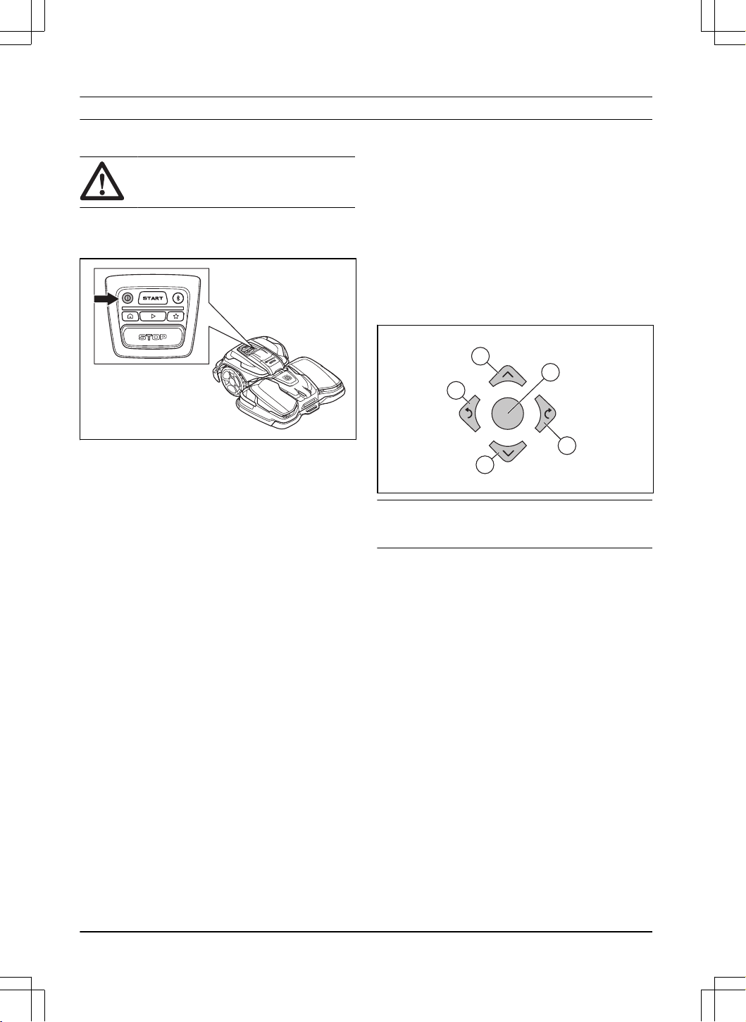
5.2 To start the product
1. Push the ON/OFF button for 3 seconds to set the
product to ON.
2. Open the Husqvarna Fleet Services
™
app.
3. Enter the PIN code.
4. Push the START button on the product.
5.3 To select operation mode
5.3.1 Scheduled operation
The product operates to the set schedule in the work
area where it cuts the grass and charges automatically.
5.3.1.1 To select scheduled operation in the app
1. Open the app on your mobile device.
2. Select
Start
>
Resume Schedule
.
5.3.1.2 To select scheduled operation in the control
panel
1. Push the STOP button.
2. Push the Play button.
3. Push the START button.
5.4 appDrive
Use the appDrive to operate the product manually.
5.4.1 To use appDrive
1. Open the app on your mobile device.
2. Select
Start
>
appDrive
.
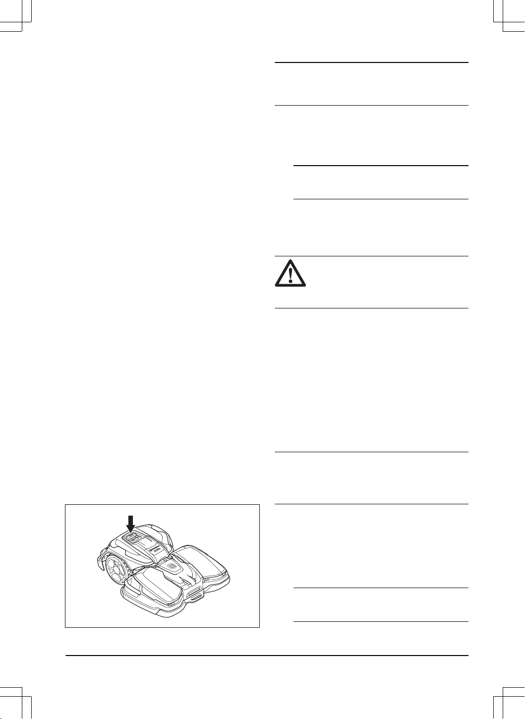
5.4.2 To operate the product with appDrive
Use the buttons to operate the product:
• Use the up button (A) to move the product forward.
• Use the down button (B) to move the product
rearward.
• Use the left arrow button (C) to rotate the product
to the left.
• Use the right arrow button (D) to rotate the product
to the right.
• Use the center button (E) as a joystick to move and
rotate the product in any direction.
A
D
B
C
E
Note: Walk 2-3 m / 6.5-9.8 ft. behind the product
when you operate the product with appDrive.
5.5 Work area selection
This function lets the product temporarily operate in a
selected work area. When the selected work area is cut,
the product continues to operate to the set schedule.
For the product to operate in a secondary area, you
must move the product manually to and from the
secondary area. The product operates until the work
area is cut or until the battery is empty.
5.5.1 To select the work area in the app
1. Open the app on your mobile device.
2. Select
Start
.
3. Select the work area.
5.6 Operation mode Park
The operation mode
Park
means that the product goes
back to the charging station. The product stays in the
charging station for a selected period of time or until you
select a new operation mode.
30
- Operation 1691 - 007 - 22.12.2023
5.6.1 To select operation mode Park in the
app
1. Open the app on your mobile device.
2. Select
Park
.
3. Select for how long the product must stay in the
charging station.
5.6.2 To select operation mode Park on the
control panel
1. Push the STOP button.
2. Push the Park button.
3. Push the START button.
The product stays in the charging station for 3 hours and
then it continues to operate to the set schedule.
5.7 Operation mode Park at
Maintenance point
You can park the product at the maintenance point to do
maintenance on the product.
5.7.1 To park the product at the
maintenance point with the app
1. Open the app on your mobile device.
2. Select
Park
>
Maintenance point
.
The product is parked at the maintenance point until you
select a new operation mode.
5.7.2 To park the product at the
maintenance point with the control panel
1. Push the STOP button.
2. Push the Maintenance point button.
3. Push the START button.
The product is parked at the maintenance point until you
select a new operation mode.
5.8 To stop the product
1. Push the STOP button on top of the product.
The product stops and the cutting motor stops.
Note:
When you push the Play and START button
again, the product continues to operate in the operating
mode
Resume Schedule
.
5.9 To set the product to OFF
1. Push the STOP button on top of the product.
2. Connect the product with Bluetooth
®
short-range in
the app.
Note: The product cannot be set to OFF if it is
not connected to the app with Bluetooth
®
.
3. Push the ON/OFF button for 3 seconds to set the
product to OFF. Make sure that the LED indicator
goes out.
5.10 To charge the battery
WARNING: Read and understand the
safety instructions for the battery before you
use the product. Refer to
Battery safety on
page 5
.
When the product is new or after long-term storage, the
battery can be empty. Charge the battery before you
start the product.
1. Push the ON/OFF button for 3 seconds to set the
product to ON.
2. Put the product into the charging station until the
charging plates touch the contact plates. Refer
to charging plates and contact plates in
Product
overview charging station, CEORA
™
CS4 on page
10
.
3. Make sure that the charging is in progress in the
Husqvarna Fleet Services
™
app or that the LED
indicator pulsates blue.
Note:
If the charging does not start automatically,
disconnect and connect the mains cable to the charging
station to restart it. The charging starts automatically
when you restart it.
5.11 To release the wheel brakes and
move the product
You can release the wheel brakes and push the product
forward to move it manually as an alternative of to lift it.
1. Push and hold the STOP button. The wheel brakes
are released after 3 seconds.
Note:
The wheel brakes enables again when
you release the STOP button.
1691 - 007 - 22.12.2023 Operation - 31

2. Keep the STOP button pushed and push the
product forward to move it.
32 - Operation 1691 - 007 - 22.12.2023
6 Maintenance
6.1 Introduction - maintenance
WARNING: Set the product to OFF
before you do maintenance on the product.
WARNING: Use protective gloves.
For better operation and lifetime of the product, make
sure to clean the product regularly and replace worn
parts. Obey the instructions in
Maintenance schedule on
page 33
.
When the product is new, examine the blade discs
and blades each week. If the wear is low, you can
increase the interval for the next time you examine the
blade discs and blades. If there is much wear, you can
decrease the interval.
It is important that the blade disc rotates easily and that
the edges of the blades are not damaged. The usual
lifetime of the blades are 1 to 4 weeks. The conditions
that follow can increase or decrease the lifetime of the
blades:
• Operation time and dimension of the work area.
• Length and thickness of the grass.
• Soil, sand and use of fertilizers.
• Objects such as cones, tools, stones and roots in
the work area.
Note: The cut result can be unsatisfactory if the
blades are blunt. Refer to
Replacement of the blades
and blade discs on page 36
on how to replace the
blades.
6.2 Maintenance schedule
The maintenance schedule shows how to do
servicing and maintenance on the product. Follow the
maintenance schedule for a better operation and to
increase the lifetime of the product.
X = Maintenance can be done by the operator.
O = The instructions are not given in this operator's
manual. Speak to your approved servicing dealer.
To prepare
Weekly
Every
year
Every
third
year
Clean the product. Refer to
Clean the product on page 36
. X
Examine the product for damage and wear. X
Do an update of the firmware for the drive unit and cutting deck. Refer to
Down-
load firmware over the air (Firmware over the air FOTA) on page 29
.
X
Do an update of the firmware for the charging station. O
Do a check of the servicing messages for recommended upgrades. O
1691 - 007 - 22.12.2023 Maintenance - 33

Servicing
Weekly
Every
year
Every
third
year
Drive unit
Remove the wheel covers and clean the wheels. Refer to
To clean the drive unit
on page 36
.
X
Examine if the cap for the USB outlet is attached correctly. X
Charge the battery fully before you put the product into storage. Refer to
To
charge the battery on page 31
.
X
Adjust the position of the wheel brushes if it is necessary or replace them if they
are worn. Refer to
Adjustment of the wheel brushes on page 38
.
X
Examine the rubber grommets on the chassis to make sure that it is sealed
correctly.
O
Examine and clean the collision columns. O
Do a check of the tightening torque of chassis screws. Examine the thread in-
serts.
O
Open the motor lid and do a check if there is leakage. O
Examine and clean the airflow filter. O
Replace the airflow filter. O
Open the chassis and replace the sealing strip. O
Open the motor lid and replace the gasket. O
Cutting deck
Examine the blades and replace the blades and blade screws if it is necessary.
Refer to
Replacement of the blades and blade discs on page 36
.
X
Examine and polish the charging plates. X
Examine bellows for cutting discs and for the front wheels. X
Examine the ultrasonic sensors and tighten the screws. O
Examine the rubber grommets in the electronic boxes. O
Examine and clean the collision columns. O
Remove the protection plate and clean the inner side. O
Examine the skid plate and skid plate bearing. O
Lubricate the cutting height adjustment motors. O
Examine the wheels for wear. O
Examine the bearings in the front wheels and wheel holders. O
Lubricate the interface between the drive unit and the cutting deck and examine
them for wear.
O
Calibrate the cutting height. O
Examine and clean the airflow filter. O
34 - Maintenance 1691 - 007 - 22.12.2023
Servicing
Weekly
Every
year
Every
third
year
Replace the airflow filter. O
Examine the charging cable and connector. O
Charging station
Examine and polish the contact plates on the charging station. X
Examine the mains cable, power supply unit, charging cable and connectors. O
Open the charging station and replace the gasket. O
Last step Weekly Every
year
Every
third
year
Use a software service tool to do a function test of the functions of the product. O
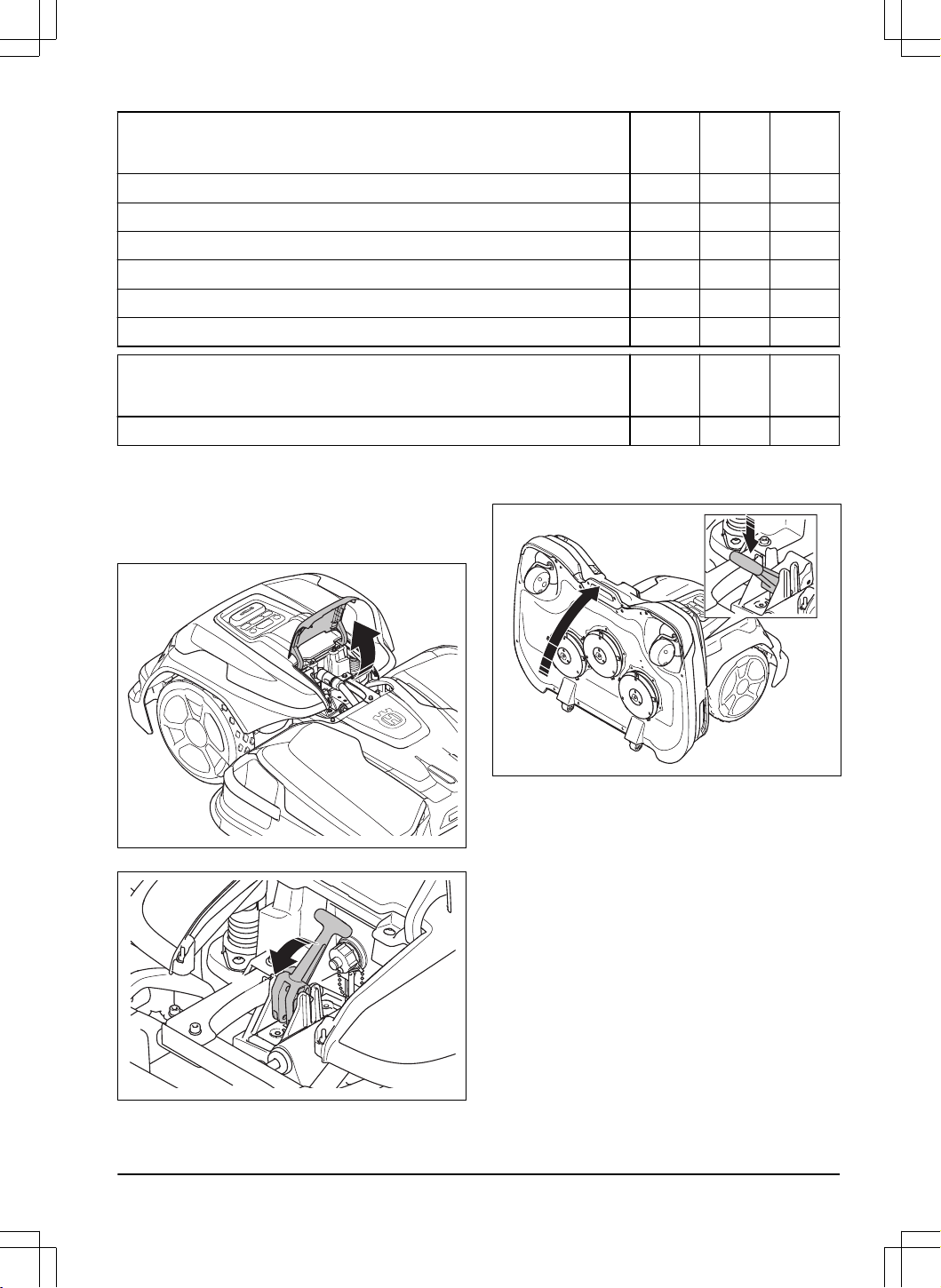
6.3 To put the cutting deck in service
position
1. Set the product to OFF. Refer to
To set the product
to OFF on page 31
.
2. Open the hatch on the drive unit.
3. Tilt the lever.
4. Push down the lever and lift up the front of the
cutting deck by the handle. Make sure that the
cutting deck is in a vertical position.
6.4 To put the cutting deck in cut
position
1. Use the front handle on the cutting deck to fold
down the cutting deck.
1691 - 007 - 22.12.2023 Maintenance - 35
2. Lift the rear part of the cutting deck and tilt the
lever.
3. Close the hatch.
6.5 Clean the product
Husqvarna recommends to use a special cleaning and
maintenance kit, available as an accessory. Speak to
your Husqvarna representative for more information.
CAUTION: Do not use a high-pressure
washer to clean the product and the
charging station. Do not use solvents for
cleaning.
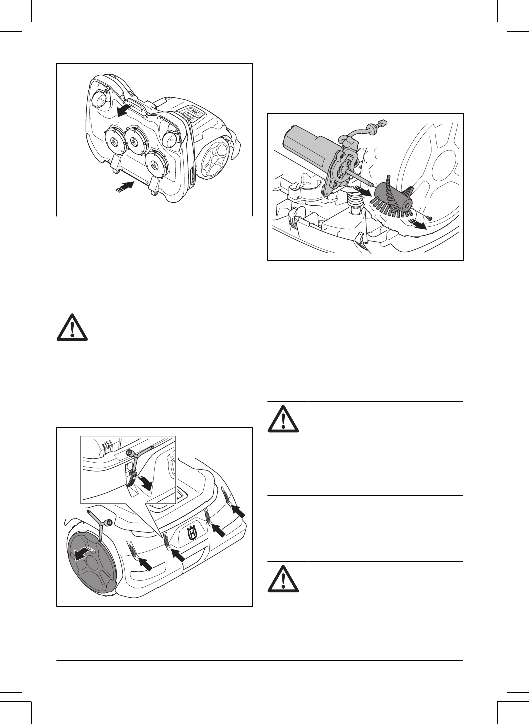
6.5.1 To clean the drive unit
The product does not operate satisfactorily in slopes if
the wheels are blocked with grass.
1. Loosen the clips with the flat screwdriver on the
Combi tool and remove the rear bumper.
2. Remove the wheel cover with the flat screwdriver
on the Combi tool.
3. Clean the body of the product, wheels and chassis
with a brush, compressed air or running water.
4. Examine and clean the wheel brushes. If
necessary, remove the screw and remove the
wheel brush to clean the shaft fully.
T20
6.5.2 To clean the cutting deck and blade
discs
Examine the blade discs and blades weekly.
1. Put the product in service position. Refer to
To put
the cutting deck in service position on page 35
.
2. Clean the blade discs, protection plate and the
wheels with a brush, compressed air and running
water.
3. Make sure that the blades are not damaged and
that the blades and blade discs can rotate freely.
6.5.3 To clean the charging station
WARNING:
Disconnect the mains
cable from the power outlet before
maintenance, or when you clean the
charging station.
Note: The product cannot go into the charging station
if there are objects in the charging station.
• Clean the charging station regularly from grass,
twigs and other objects.
6.6 Replacement of the blades and
blade discs
WARNING:
Husqvarna can only
guarantee safety with the specified
Husqvarna original blades. Refer to
Technical data on page 53
.
36 - Maintenance 1691 - 007 - 22.12.2023
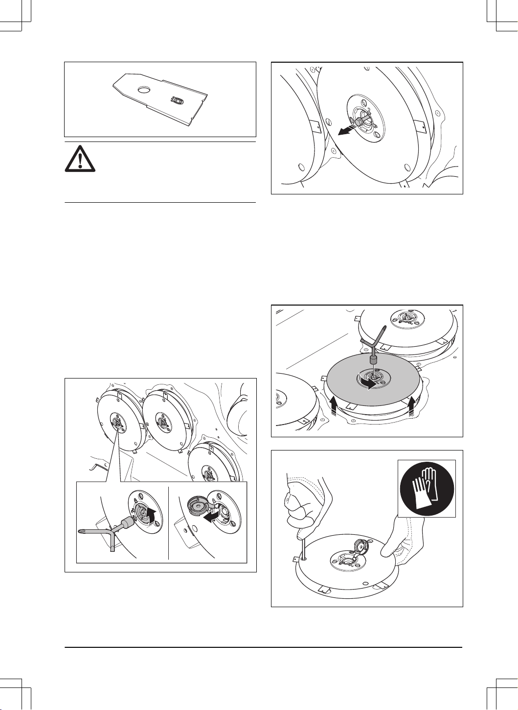
WARNING: You must replace the
screws when you replace the blades. The
used screws can wear quickly and make the
blade come loose, this can cause serious
injury.
Replace worn or damaged blades for a safe operation.
Replace the blades regularly for a satisfactory cut result
and a low energy use. All 5 blades and screws must
be replaced at the same time to get a balanced cutting
system. After half the lifetime of the blades, the left
and right cutting disc must switch positions to wear the
blades equally. The blades can be replaced when the
blade discs are installed on the product. You can also
remove the blade discs and then replace the blades.
6.6.1 To replace the blade discs
1. Push the STOP button.
2. Set the product to OFF.
3. Put the cutting deck in service position. Refer to
To
put the cutting deck in service position on page 35
.
4. Remove the coupling on the blade disc with the
Combi tool.
5. Loosen the screw with the Combi tool.
6. Remove the blade disc.
7. Clean the shaft and hub if it is dirty.
8. Install the blade disc in opposite sequence.
6.6.2 To replace the blades on the blade
disc
1. If there are no holes in the skid plate, remove the
skid plate:
a) Lift up the skid plate and remove the screw
with the Combi tool to remove the skid plate.
2. Remove the 5 screws.
3. Remove the 5 blades.
1691 - 007 - 22.12.2023
Maintenance - 37
4. Install 5 new blades and screws.
5. Make sure that the blades can pivot freely.
6. If the skid plate was removed, install the skid plate
and the screw. Tightening torque 8 Nm.
6.7 Adjustment of the wheel brushes
The wheel brushes must be adjusted if they are worn.
6.7.1 To adjust the wheel brushes
1. Push the STOP button.
2. Set the product to OFF.
3. Loosen the clips with the flat screwdriver on the
Combi tool and remove the rear bumper.
4. Loosen the screw with a T27 screwdriver to adjust
the wheel brushes. Make sure that the brushes
touches the bottom of the wheel threads.
0mm
6.8 Battery
CAUTION:
Charge the battery fully
before you put the product into storage. If
the battery is not fully charged it can cause
damage to the battery.
If the operating time of the product is shorter than usual
between charges, this means that the battery is at the
end of its life cycle. Replace the battery to extend the
operating time.
Note:
The battery life is related to the length of
the season and how many hours a day the product
operates. A long season or many hours of operation
a day means that the battery must be replaced more
regularly.
38 - Maintenance 1691 - 007 - 22.12.2023

7 Troubleshooting
7.1 Introduction - troubleshooting
You can find all the troubleshooting messages in the
Messages
menu in Husqvarna Fleet Services
™
. You can find
more information on www.husqvarna.com.
7.2 Fault messages
The fault messages in the table below are shown in the Husqvarna Fleet Services
™
app. Speak to your approved
servicing dealer if the same message shows frequently.
Message Cause Action
Cutting system blocked
The cutting motor is blocked by grass or
other objects.
Examine the cutting motor and remove
grass or other objects.
The blade disc is in water. Move the product and prevent the collec-
tion of water in the work area.
The grass is too high. Adjust the cutting height to the height of
the grass.
Adjust the schedule settings to increase
the operation time.
Trapped
The product is behind a number of obsta-
cles in a small area.
Examine the area and remove the obsta-
cles which make it hard for the product to
move away from this location.
1691 - 007 - 22.12.2023 Troubleshooting - 39
Message Cause Action
No loop signal
The mains cable is not connected. If the LED indicator on the charging sta-
tion is out, it shows that there is no pow-
er. Examine the power outlet connection
and the residual-current device. Make
sure that the mains cable is connected
to the charging station.
The mains cable is damaged. Replace the mains cable.
ECO mode
is enabled and the LED in-
dicator of the charging station flashes
green. The product was started manually
in the work area but the STOP button
was not pushed before the product was
moved from the charging station. The
charging station signal is disabled and
the product cannot enter the charging
station. Refer to
ECO mode on page 28
.
Put the product in the charging station.
Start the product. Refer to
To start the
product on page 30
.
The product does not find the loop signal
from the charging station.
Put the product in the charging station
and make a new loop signal. Refer to
To
reinstall the charging station on the map
on page 25
.
The charging station in not installed cor-
rectly.
Install the charging station correctly. Re-
fer to
Installation of the charging station
on page 20
.
Interference from metal objects such as
fences, reinforcement steel or buried ca-
bles near the charging station.
Change the position of the charging sta-
tion.
Outside work area
The work area slopes too much by the
virtual boundary.
Make sure that the virtual boundary is
installed correctly. Refer to
To install map
objects near buildings and trees on page
16
.
The transport path or the path to the
maintenance point slopes too much.
Make sure that the transport path is in-
stalled correctly. Refer to
To install map
objects near buildings and trees on page
16
.
The product can not find the correct loop
signal because of interference with a
loop signal from a different product instal-
lation nearby.
Put the product in the charging station
and make a new loop signal. Refer to
To
reinstall the charging station on the map
on page 25
.
Interference from metal objects such as
fences, reinforcement steel or buried ca-
bles near the charging station.
Change the position of the charging sta-
tion.
40 - Troubleshooting 1691 - 007 - 22.12.2023

Message Cause Action
Empty battery
The product cannot find the charging sta-
tion.
The product has no accurate position
and cannot find the charging station.
There is an obstacle that prevents the
product to find the charging station.
The battery is at the end of its life cycle. Replace the battery. Refer to
Battery on
page 38
.
The product cannot enter the charging
station because the antenna in the base-
plate of the charging station is damaged.
If the LED indicator on the charging
station flashes red, the antenna of the
charging station is damaged. Speak to
your authorized service center.
Slipped
The product hit an obstacle and stopped
or the wheels cannot move on the wet
grass.
Move the product and correct the cause
of problem. If it is because of wet grass,
wait until the lawn is dry before you use
the product.
The work area includes a steep slope. Maximum slope is 45%. Isolate steep
slopes. Refer to
To install the map ob-
jects in a slope on page 18
.
Charging station blocked
The connection between the charging
plates on the product and the contact
plates on the charging station is not
good. The product made a number of
tries to charge.
Put the product in the charging station
and make sure that the charging plates
and contact plates are connected.
Clean the contact plates on the charging
station and the charging plates on the
product.
An object prevents the product to enter
the charging station.
Remove the object.
The charging station tilts or is bent. Put the baseplate on level ground. If you
install the charging station on a soft sur-
face, use the support plate accessory.
Stuck in charging station
The product cannot move out from the
charging station because it is blocked.
The baseplate has a wet or dirty surface
that prevents the product to move out
from the charging station.
Examine why the product cannot move
out from the charging station. Remove
objects and clean the baseplate of the
charging station.
Charging station communica-
tion problem
Make a new charging station signal a
number of times. If the problem stays,
speak to your authorized service center.
The signal of the charging station was
not changed.
Do a pairing operation between the prod-
uct and the charging station. If the prob-
lem stays, speak to your authorized serv-
ice center.
The product is not connected to the
charging station.
Power failure. Examine and correct the cause of the
power failure.
Upside down
The product tilts or the body of the prod-
uct is with the top down.
Put the product in the correct position.
Mower tilted
The product tilts more than the maximum
angle.
Move the product to an area that has lev-
el ground.
1691 - 007 - 22.12.2023 Troubleshooting - 41
Message Cause Action
Lifted
The lift sensor was enabled because the
product was lifted.
Make sure that the body of the product
can move freely around its chassis. Re-
move or make a stay-out zone around
objects that can cause the body of the
product to be lifted. If the problem stays,
speak to your authorized service center.
Collision
The body of the product cannot move
freely around its chassis.
Remove dirt or object between the chas-
sis and the body of the product. Make
sure that the body of the product can
move freely around its chassis.
The product cannot move forward or
rearward.
Remove the object that prevents the
product from operation.
Wheel motor blocked right/
left
The wheel is blocked by grass or other
objects.
Examine the wheel and remove grass or
other objects.
Alarm! Mower stopped
The alarm was started because the prod-
uct was stopped.
Adjust the security settings in the
Securi-
ty
menu. Refer to
Security on page 28
.
Alarm! Mower outside Geo-
fence
Alarm was started because the product
was moved out of the GeoFence area.
Alarm! Mower was moved
The alarm was started because the prod-
uct was moved.
Electronic problem
Temporary electronic or firmware prob-
lem in the product.
Restart the product. If the problem stays,
speak to your approved servicing dealer.
Loop sensor problem
Charging system problem
Tilt sensor problem
Temporary problem
Invalid sub-device combina-
tion
Collision sensor problem
Lift sensor problem
Invalid system configuration
Safety function faulty
Docking sensor problem
Cutting motor problem
Cutting deck folding sensor
problem
Internal voltage problem
Internal communication prob-
lem
42 - Troubleshooting 1691 - 007 - 22.12.2023

Message Cause Action
Battery problem
Temporary battery or firmware problem
in the product.
Restart the product. If the problem stays,
speak to your approved servicing dealer.
Incorrect type of battery. Use original batteries recommended by
the manufacturer.
The battery is damaged or do not oper-
ate correctly.
Replace the battery, speak to your au-
thorized service center.
Battery temperature outside
limits
The product cannot start because the
temperature in the battery is too high or
too low.
The product will start to operate when
the temperature of the battery has de-
creased. Make sure that the charging
station is put in an area with protection
from the sun.
Charging current too high
Incorrect or damaged power supply unit. Examine that the power supply unit and
charging station are not damaged. Make
sure that you use the correct power sup-
ply unit and charging station. Restart the
product. If the problem stays, speak to
your authorized service center.
Map problem
There is no specified work area. Make a work area in the Husqvarna Fleet
Services
™
app. Refer to
To make a work
area on page 23
.
The map object file is incorrect. Do a check of the map in the app. Adjust
the map and save it.
Delete the map and do a new installation.
Work area tampered
The charging station or the reference sta-
tion was moved.
Move the charging station or the refer-
ence station to their initial positions.
Do a new installation of the map.
Wheel drive problem, right/
left
The wheel is blocked by grass or other
objects.
Examine the drive wheel and remove
grass or other objects.
No power in charging station
The power supply unit is incorrect or
damaged.
Examine the power supply unit. Replace
it if necessary.
Power failure. Examine and correct the cause of the
power failure.
The product cannot charge because the
contact plates and the charging plates
are not connected.
Make sure that the charging plates and
the contact plates are connected. Clean
the contact plates and charging plates.
1691 - 007 - 22.12.2023 Troubleshooting - 43

Message Cause Action
Searching for satellites
Weak satellite signal to the reference sta-
tion.
The satellite signal is temporary weak.
The product will start to operate when the
satellite signals are good.
Examine the installation of the reference
station. Refer to the Operator's manual
for the Reference station.
Weak satellite signal to the product. The satellite signal is temporary weak.
The product will start to operate when the
satellite signal are good.
Examine if there is an object between
the product and the sky that cause inter-
ference with the satellite signal. Remove
the object or do a new installation to not
include these parts in the work area. Re-
fer to
To make a work area on page 23
No accurate position from
satellites
Weak satellite signal to the reference sta-
tion.
Examine the installation of the reference
station. Refer to the Operator's manual
for the Reference station.
Weak satellite signal to the product. Examine if there is an object between
the product and the sky that cause inter-
ference with the satellite signal. Remove
the object or do a new installation to not
include these parts in the work area. Re-
fer to
To make a work area on page 23
44 - Troubleshooting 1691 - 007 - 22.12.2023
Message Cause Action
Reference station communi-
cation problem
There is no radio signal between the
product and the reference station.
Do a pairing operation between the prod-
uct and the reference station.
The reference station is not installed cor-
rectly.
Examine the installation of the reference
station. Refer to the Operator's manual
for the Reference station.
The product does not receive the radio
signal from the reference station in all of
the work area.
Examine if the product has radio signal
from the reference station in the full work
area. If not, make a new installation of
the reference station or a new installation
of the map. Refer to
Installation of the
map objects on page 21
.
Install a second reference station to op-
erate as a repeater. Make sure that the
product can receive the radio signal.
Speak to your Husqvarna representative
for more information.
Power failure. Examine and correct the cause for the
power failure of the reference station.
Install a second reference station to op-
erate as a repeater. Speak to your Husq-
varna representative for more informa-
tion.
There is an error in the reference station
and the LED indicator flashes red.
Disconnect the power to the reference
station and connect it again to restart the
reference station. If the problem stays,
speak to your approved servicing dealer.
Unexpected cutting height adj
The cutting height adjustment cannot
move.
Examine the cutting height adjustment
and remove grass or other objects. If the
problem stays, speak to your approved
servicing dealer.
Limited cutting height range
Cutting height problem
Cutting height blocked
Cutting deck not in correct
position
The cutting deck is not attached correct-
ly.
Make sure that the cutting deck is at-
tached correctly and that the lever is in
the correct position. If the problem stays,
speak to your authorized service center.
The cutting deck is in service position. Make sure that the cutting deck is in cut
position. If the problem stays, speak to
your authorized service center.
Destination not reachable
There is no transport path between the
charging station and the work area or
maintenance point.
Make a transport path between the
charging station and the work area or
maintenance point.
The transport path is blocked and the
product cannot go to the work area,
charging station or maintenance point.
Make sure that the transport path is not
blocked, or delete the transport path and
make a new transport path.
Too many waypoints
There are too many waypoints in the cur-
rent work area.
Make a new the work area, stay-out
zone and transport path and use less
waypoints. Divide the current work area
into more work areas.
1691 - 007 - 22.12.2023 Troubleshooting - 45
Message Cause Action
Too high battery current
The product has stopped because it has
operated on too high or thick grass or in
a too steep slope.
Put the product on a level surface with
short grass and start the product. If the
problem stays, speak to your authorized
service center.
Too high internal current
High internal power loss
High charging power loss
The contact between the charging plates
on the cutting deck and the contact
plates on the charging station is not
good.
Polish the charging plates on the cutting
deck and the contact plates on the charg-
ing station.
Temporary electronic or firmware prob-
lem in the product.
Start the product. If the problem stays,
speak to your authorized service center.
High internal temperature
The product has operated in too high
temperature, too high or thick grass, or
in too steep slopes.
Put the product in an area with protection
from the sun and wait. Put the product on
a level surface with short grass and start
the product. If the problem stays, speak
to your authorized service center.
High temperature in cutting
motor, right/center/left
Multiple reference stations
There is more than one reference station
near the work area. This can cause inter-
ference for the product from a different
reference station.
Speak to your approved servicing dealer
if the same problem occurs frequently.
Invalid firmware configuration
The firmware in the product is not upda-
ted.
Put the product in the charging station
and update the firmware. If the problem
stays, speak to your dealer.
7.3 Information and warning messages
The information messages in the table below are shown in the
Messages
menu in the Husqvarna Fleet Services
™
app. Speak to your approved servicing dealer if the same message shows frequently.
Message
Cause Action
Cutting system imbalance
The product senses vibrations in the cut-
ting disc.
Examine the blades and screws for dam-
ages and wear. Make sure that all blades
are correctly installed and that there is
only one blade attached in each position
on the blade disc.
Connectivity problem
Problem with the Automower
®
Connect
module.
Restart the product. Disable Automower
®
Connect in the app and enable it again.
Wait 1 hour and try again. If the problem
stays, speak to your local approved serv-
icing dealer.
Wrong PIN code
An incorrect PIN code was entered. 5
tries are permitted, and the product is
then blocked for a period of time.
Enter the correct PIN code. If the PIN
code is incorrect, use the web address in
the app to send the PIN code to your reg-
istered e-mail address. If you have not
registered the e-mail address, speak to
your approved servicing dealer.
GPS navigation problem
Temporary electronic or firmware related
problem in the product.
Restart the product. If the problem stays,
speak to your approved servicing dealer.
Ultrasonic problem
The ultrasonic sensor is dirty or blocked. Clean the ultrasonic sensor.
Temporary electronic or firmware related
problem in the product.
Restart the product. If the problem stays,
speak to your approved servicing dealer.
46 - Troubleshooting 1691 - 007 - 22.12.2023

7.4 LED indicator lamps on the charging station
For a fully functional installation, the indicator lamps in the charging station must show a solid or flashing green light. If
another color shows, follow the troubleshooting guide below.
There is more help on www.husqvarna.com. If you still need help, speak to your approved servicing dealer.
Light Status
Green solid light Good signals.
Green flashing light The signals are good and
ECO mode
is activated. Refer to
ECO mode on page 28
.
Red flashing light Interruption in the charging station’s antenna. Speak to your approved servicing
dealer.
Red solid light Fault in the circuit board or incorrect power supply in the charging station. The
fault must be correct by an authorized service technician. Speak to your approved
servicing dealer.
7.5 Symptoms
If the product does not operate correctly, refer to the symptoms table below.
Symptoms
Cause Action
The product cannot go into
the charging station.
The charging station is not put on a level
surface.
Put the charging station on level surface.
Refer to
To examine where to put the
charging station on page 14
.
The charging station is put too far from
the work area.
Make a new work area or move the
charging station.
The product operates at the
incorrect time.
The time and date of the product must be
set.
Set the time and date. Refer to
Time &
date on page 28
.
The time and date of the product is not
set correctly.
The start and stop time for operating are
incorrect.
Change the schedule settings. Refer to
Schedule on page 27
.
There is vibration in the prod-
uct.
The cutting system is not in balance be-
cause of damaged blades.
Examine the blades and screws and re-
place them if it is necessary. Refer to
Re-
placement of the blades and blade discs
on page 36
.
The cutting system is not in balance be-
cause of too many blades in the same
position.
Make sure that only 1 blade is attached
to each screw.
Blades of different thickness are installed
on the product.
Examine if the blades are of different
thickness and replace the blades if nec-
essary.
The product operates, but the
blade disc does not rotate.
The product goes to the charging station. Usual operation for the product. The
blade disc does not rotate when the
product goes to the charging station.
1691 - 007 - 22.12.2023 Troubleshooting - 47
Symptoms Cause Action
The product operates for
shorter periods than usual
between charges.
Grass or other object causes a blockage
to the blade disc.
Remove and clean the blade disc. Refer
to
To clean the cutting deck and blade
discs on page 36
.
The battery is at the end of its life cycle. Replace the battery. Refer to
Battery on
page 38
.
The grass is high and thick. Increase the cutting height and then de-
crease it when the grass is shorter.
Operation and charging times
are shorter than usual.
The battery is at the end of its life cycle. Replace the battery. Refer to
Battery on
page 38
.
The product is parked for
hours in the charging station.
The product is parked because of the set
schedule setting, or because
Park until
further notice
is selected.
Change the schedule settings, or start
the product.
The product does not operate if the bat-
tery temperature is too high or too low.
The product starts to operate again when
the temperature is between the set limits
and the schedule settings lets the prod-
uct operate. Make sure that the charging
station is put in an area with protection
from the sun.
The cut result is not satisfac-
tory.
The product operates for a short period. Increase the operation time. Refer to
Schedule on page 27
.
The work area is too large. Set a limit to the work area, or extend
the operation time. Refer to
Schedule on
page 27
.
Blunt blades. Replace all the blades. Refer to
To re-
place the blades on the blade disc on
page 37
.
Long grass in relation to the set cutting
height.
Increase the cutting height and then de-
crease it when the grass is shorter.
Collection of grass on the blade disc or
around the motor shaft.
Remove the collection of grass and clean
the product. Refer to
To clean the cutting
deck and blade discs on page 36
.
The cutting deck is not calibrated. Speak to your authorized service center.
The product is in the charging
station but does not charge
the battery.
The product is not connected to the
charging station.
Make a pairing operation to connect the
charging station and the product.
The charging station does not charge. Disconnect and connect the mains cable
to the charging station to restart it and
to automatically start the charging. If the
problem stays, speak to your dealer.
You cannot connect with the
product with an additional
mobile device.
Only one mobile device can be connec-
ted to the product with Bluetooth
®
at the
same time.
Close the Automower
®
Connect app in
all other connected devices. If the prob-
lem stays, set the connected mobile de-
vice to OFF and start it again. If the prob-
lem stays, speak to your dealer.
48 - Troubleshooting 1691 - 007 - 22.12.2023

Symptoms Cause Action
There was cellular connec-
tion before, but there is no
cellular connection at this
time.
There is a problem with the cellular con-
nection.
• Make sure that you have cellular
coverage in the area.
• Disable Automower
®
Connect in
the app and enable it again. Wait
1 hour and try again.
• Restart the product.
• If a new firmware is available in the
app, install it to make sure that you
have the newest firmware.
• Make sure that you have the new-
est version of the Husqvarna Fleet
Services
™
app and the Automow-
er
®
Connect app installed.
• If the problem stays, speak to your
dealer.
1691 - 007 - 22.12.2023 Troubleshooting - 49
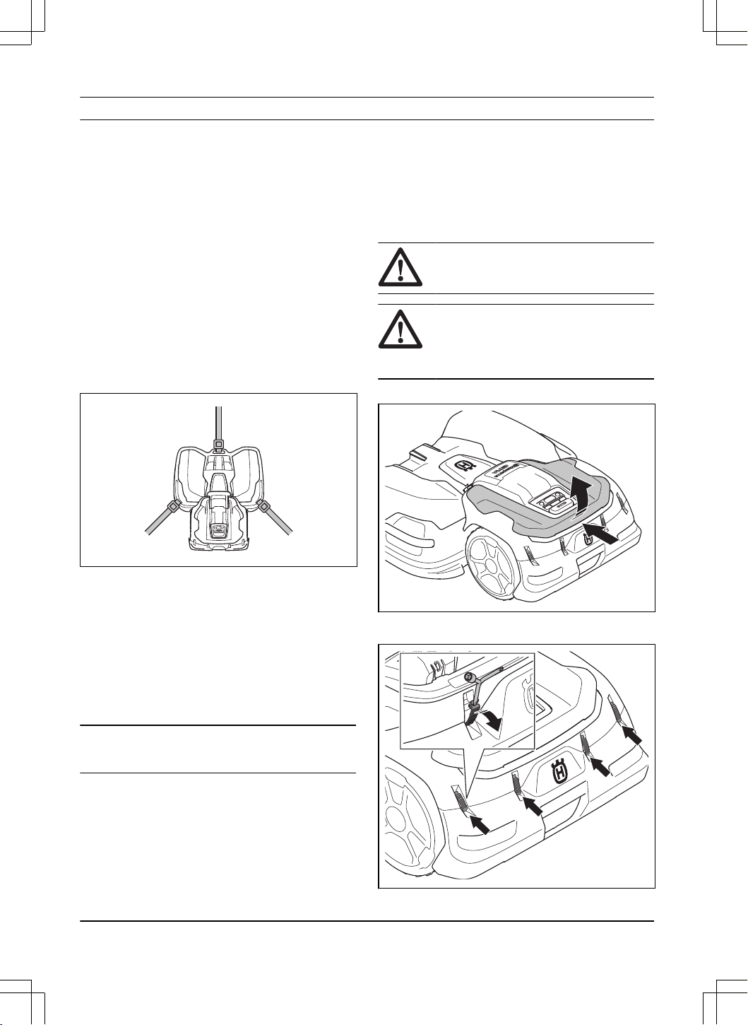
8 Transportation, storage and disposal
8.1 Safety instructions for
transportation
• Use an approved transport vehicle for
transportation of the product.
• A markets national or local regulations can set limit
to the transportation of the product.
• The operator of the transport vehicle is responsible
to attach the product safely during transport. Refer
to
To safely attach the product for transport on
page 50
.
8.1.1 To safely attach the product for
transport
• Attach the product with 3 straps, one on the
front handle and one on each side handle of the
product. The maximum force is 300 N for each
strap.
8.2 To put the product into storage
• Charge the product fully. Refer to
To charge the
battery on page 31
.
• Set the product to OFF. Refer to
To set the product
to OFF on page 31
.
• Clean the product. Refer to
Clean the product on
page 36
.
• Put the product in a dry, frost-free area.
• Put the product with all wheels on level ground.
Note:
If you keep the charging station outdoors, do
not disconnect the cable.
8.3 Transportation of batteries
The supplied Li-ion batteries obey the Dangerous Goods
Legislation requirements.
• Obey all applicable national regulations.
• Obey the special requirement on package and
labels for commercial transportations, including by
third parties and forwarding agents.
8.4 Disposal
• Obey the local recycling requirements and
applicable regulations.
• For questions about how to remove the battery,
refer to
To remove the battery on page 50
.
8.4.1 To remove the battery
WARNING: Use protective gloves and
protective shoes.
CAUTION: Only remove the batteries
when you dispose the product. The
Husqvarna warranty is not applicable if you
remove the warranty seal.
1. Remove the top cover.
2. Loosen the clips with the flat screwdriver on the
Combi tool and remove the rear bumper.
50
- Transportation, storage and
disposal
1691 - 007 - 22.12.2023
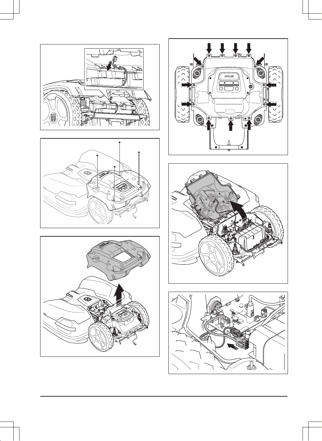
3. Disconnect the cable.
4. Remove the 4 nuts.
5. Remove the body of the product.
6. Remove the 13 screws.
7. Fold the top of the chassis carefully.
8. Disconnect the 2 cables from the battery.
9. Remove the 4 screws for the battery bracket.
1691 - 007 - 22.12.2023
Transportation, storage
and disposal - 51
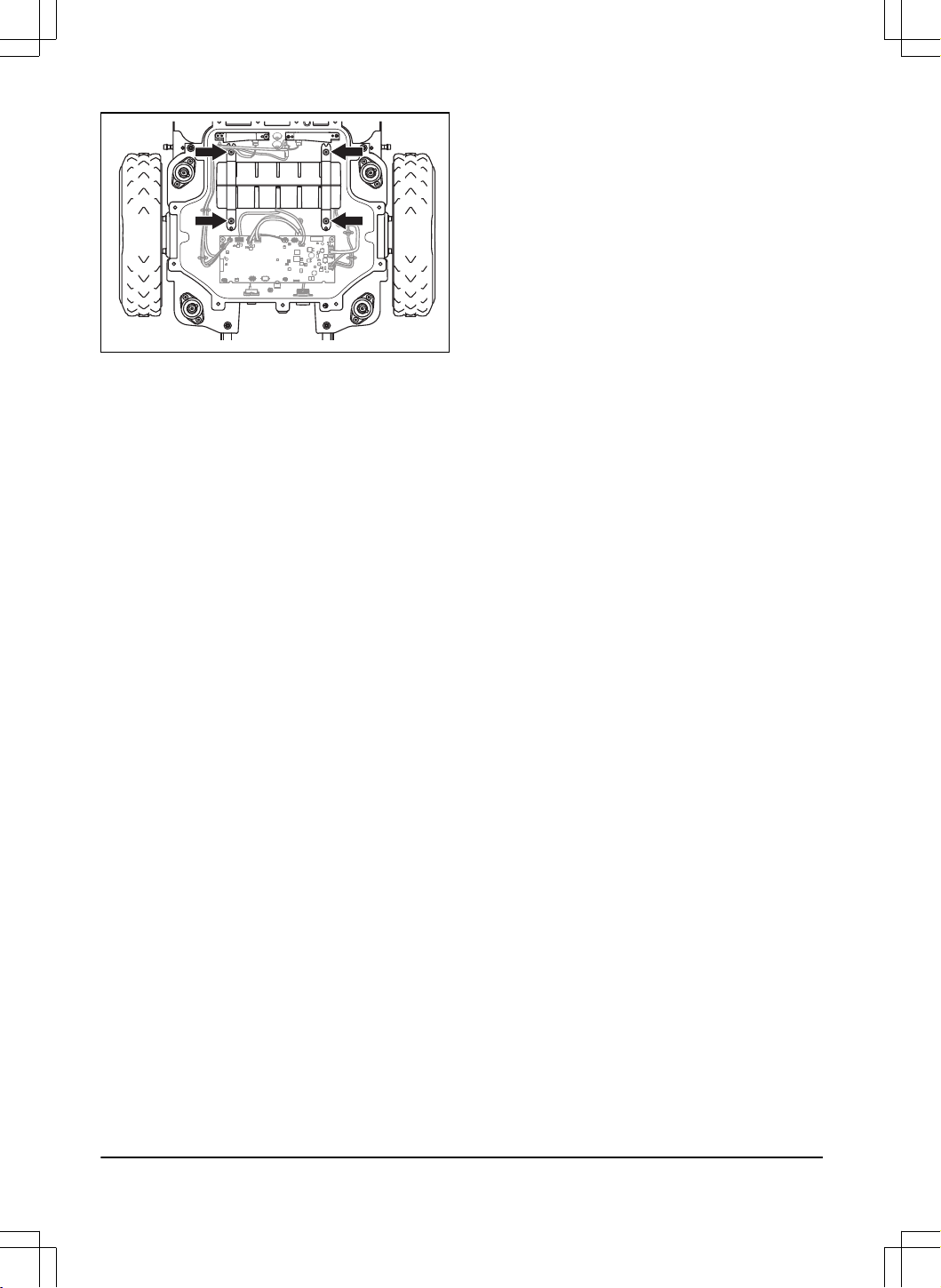
10. Remove the battery from the product.
52 - Transportation, storage and
disposal
1691 - 007 - 22.12.2023

9 Technical data
9.1 Technical data
System CEORA
™
544 EPOS CEORA
™
546 EPOS
CEORA
™
CS4 CEORA
™
CS4
CEORA
™
RZ 43L CEORA
™
RZ 43M CEORA
™
RZ 43L CEORA
™
RZ 43M
Dimensions, drive unit and cutting deck
Length, cm/in. 124/48.8 124/48.8 124/48.8 124/48.8
Width, cm/in. 108/42.5 108/42.5 108/42.5 108/42.5
Height, cm/in. 44/17.3 44/17.3 44/17.3 44/17.3
Weight
10
, kg/lb 73/161 72/160 73/161 72/160
Mowing
11
Area capacity - Max 72, m
2
/
acre(s), regular quality
57000/14.1 60000/14.8 72000/17.8 75000/18.5
Area capacity - Standard 48,
m
2
/acre(s), pro quality
38000/9.4 40000/9.9 48000/11.9 50000/12.4
Area capacity - Sports 24,
m
2
/acre(s), pro sport quality
19000/4.7 20000/4.9 24000/5.9 25000/6.2
Area per hour, no charging,
m
2
/acre(s)
1350/0.33 1350/0.33 1800/0.44 1800/0.44
Power consumption during
cutting, average, W
270 210 310 250
Maximum blade motor
speed, rpm
2800 2800 3000 3000
Mean energy consumption at
maximum use, kWh/month
140 115 150 130
Mowing time, average, min 225 300 200 250
Charging time, average, min 150 150 150 150
Narrowest possible passage,
m/ft.
3/9.8 3/9.8 3/9.8 3/9.8
Maximum slope inside instal-
lation, %
20 20 20 20
Maximum slope for virtual
boundary, %
15 15 15 15
Sound data
12
10
Some products have wheel brushes that has a weight of 2 kg/4.4 lb.
11
The type and condition of the blades, growth and moisture of the grass can have an effect on the area
capacity. If the cutting height is lower than 25 mm, the area capacity is decreased by approximately 10%.
12
Determined according to Directive 2006/42/EC and standard EN 50636-2-107. Except Sound level, perceived
that is measured according to ISO 11094:1991.
1691 - 007 - 22.12.2023 Technical data - 53
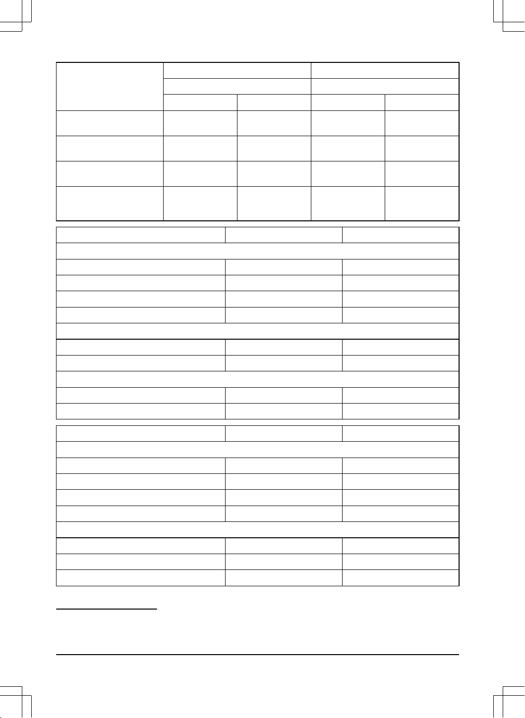
System CEORA
™
544 EPOS CEORA
™
546 EPOS
CEORA
™
CS4 CEORA
™
CS4
CEORA
™
RZ 43L CEORA
™
RZ 43M CEORA
™
RZ 43L CEORA
™
RZ 43M
Sound level perceived, dB
(A)
72 69 72 72
Measured sound power
noise level, dB (A)
70 68 70 69
Noise emissions uncertain-
ties K
WA
, dB (A)
2 1 5 1
Sound pressure noise level
at the operator’s ear
13
, dB
(A)
62 60 62 61
Drive unit CEORA
™
544 EPOS CEORA
™
546 EPOS
Dimensions
Length, cm/in. 67/26.4 67/26.4
Width, cm/in. 72/28.3 72/28.3
Height, cm/in. 44/17.3 44/17.3
Weight
14
, kg/lb 38/84 38/84
Battery
Battery, Lithium-Ion 36.3V, 49 Ah, Art. No 593 78 54-01 593 78 54-01
Battery, Lithium-Ion 36.9V, 48 Ah, Art. No 593 78 54-02, 593 78 54-03 593 78 54-02, 593 78 54-03
Product data
Speed km/h / mph 2.7/1.7 3.6/2.2
IP code IPX5 IPX5
Cutting deck CEORA
™
RZ 43L CEORA
™
RZ 43M
Dimensions
Length, cm/in. 78/30.7 78/30.7
Width, cm/in. 108/42.5 108/42.5
Height, cm/in. 34/13.4 34/13.4
Weight, kg/lb 35/77 34/75
Cutting system
Cutting system 3 discs with 5 pivoting blades 3 discs with 5 pivoting blades
Cutting height
15
, mm/in. 10-60/0.4-2.4 20-70/0.8-2.8
Cutting width, cm/in. 68/26.8 68/26.8
13
Sound pressure noise uncertainties K
pA
, 2-4 dB (A).
14
Some products have wheel brushes that has a weight of 2 kg/4.4 lb.
15
Soil type, grass type and surface type can cause different cutting heights.
54 - Technical data 1691 - 007 - 22.12.2023

Cutting deck CEORA
™
RZ 43L CEORA
™
RZ 43M
IP code IPX5 IPX5
Blades Automower
®
standard blades,
Automower
®
Enhance HSS
blades
Automower
®
standard blades,
Automower
®
Enhance HSS
blades
Charging station CEORA
™
CS4
Dimensions
Length, cm/in. 151/59.4
Width, cm/in. 98/38.6
Height, cm/in. 33/13.0
Weight, kg/lb 15.5/34.2
Electrical system
Power supply (36V DC), V AC 100-240
Mains cable for charging station, length m/ft 3/9.8
Charging current, A DC 12
Type of Power Supply Unit for charging station
16
ADP-500BR XX
IP code charging station IPX4
IP code power supply unit IPX44
Charging station wire antenna
Operating Frequency Band, Hz 100-80000
Maximum magnetic field, dBuA/m 82
Maximum Radio-frequency power
17
, mW @60m <25 mW @60m
Frequency Band Support
Bluetooth
®
Frequency range 2400.0-2483.5 MHz
Automower
®
Connect 2G GSM 850 MHz, E-GSM 900 MHz, DCS 1800 MHz, PCS 1900 MHz
Automower
®
Connect 4G Band 12 (700 MHz), Band 17 (700 MHz), Band 13 (700 MHz), Band 20 (800 MHz),
Band 26 (850 MHz), Band 5 (850 MHz), Band 19 (850 MHz), Band 8 (900 MHz),
Band 4 (1700 MHz), Band 3 (1800 MHz), Band 2 (1900 MHz)
SRD868 (Europe) 863-870 MHz
SRD915 (North America) 902-928 MHz
SRD915 (Australia) 915-928 MHz
SRD915 (New Zealand) 915-928 MHz
16
XX, YY can be any alphanumeric characters or blank for marketing purpose only, no technical differences.
17
Maximum active output power to antennas in the frequency band in which the radio equipment operates.
1691 - 007 - 22.12.2023 Technical data - 55
Power Class
Bluetooth
®
Output power 8 dBm
Automower
®
Connect 2G Power Class 4 (GSM/E-GSM) 33 dBm
Power Class 1 (DCS/PCS) 30 dBm
Power Class E2 (GSM/E-GSM) 27 dBm
Power Class E2 (DCS/PCS) 26 dBm
Automower
®
Connect 4G Power Class 3 23 dBm
SRD868 (Europe) 13 dBm
SRD915 (North America) 13 dBm
SRD915 (Australia) 13 dBm
SRD915 (New Zealand) 13 dBm
Full compatibility cannot be guaranteed between the product and other types of wireless systems such as remote
controls, radio transmitters, hearing loops, buried electric animal fencing or similar.
The products are made in England or the Czech Republic. See information on the rating plate. Refer to
Introduction
on page 7
.
9.2 Registered trademarks
The
Bluetooth
®
word mark and logos are registered trademarks owned by
Bluetooth SIG, inc.
and any use of such
marks by Husqvarna is under license.
56 - Technical data 1691 - 007 - 22.12.2023

10 Declaration of Conformity
10.1 Original EU Declaration of Conformity
1691 - 007 - 22.12.2023 Declaration of Conformity -
57
10.2 Translated EU Declaration of Conformity
We, Husqvarna AB, SE 561 82 Huskvarna, SWEDEN,
Tel. +46 36 146500 declare on our sole responsibility
that the product:
Description Robotic lawn mower
Brand Husqvarna
Type/Model HUSQVARNA CEORA
™
544/546 EPOS
Identification Serial numbers dating from 2023 week 2
complies fully with the following EU directives and
regulations:
Directive/Regulation Description
2006/42/EC "Relating to machinery"
2014/53/EU "Relating to radio equipment"
2011/65/EU "Restriction of use of certain hazardous substances"
and that the following standards and/or technical
specifications are applied;
• IEC 60336-1:2010+A1:2013+A2:2016 (EN
60335-1:2012+AC:2014+A11:2014+A13:2017)
• IEC 60335-2-107:2017+A1:2020 (EN
50636-2-107:2015+A1:2018+A2:2020)
• EN ISO 12100:2010
• EN IEC 63000:2018
• EN 61000-6-1:2007
• EN 61000-6-3:2007+A1:2011+AC:2012
• ETSI EN 301 489-1 V2.2.3
• ETSI EN 301 489-3 V2.1.1
• ETSI EN 301 489-17 V3.1.1
• ETSI EN 301 489-19 V2.1.1
• ETSI EN 301 489-52 V1.1.0
• ETSI EN 303 447 V1.3.1
• ETSI EN 300 328 V2.2.2
• ETSI EN 300 220-1 V3.1.1
• ETSI EN 300 220-2 V3.1.1
• ETSI EN 301 908-1 V15.1.1
• ETSI EN 301 908-13 V13.1.1
• ETSI EN 301 511 V.12.5.1
• ETSI EN 303 413 V1.2.1
Manne Alzén
Huskvarna
Director Pro Robotics R&D Husqvarna AB. Husqvarna
Division. Responsible for technical documentation.
58 - Declaration of Conformity 1691 - 007 - 22.12.2023
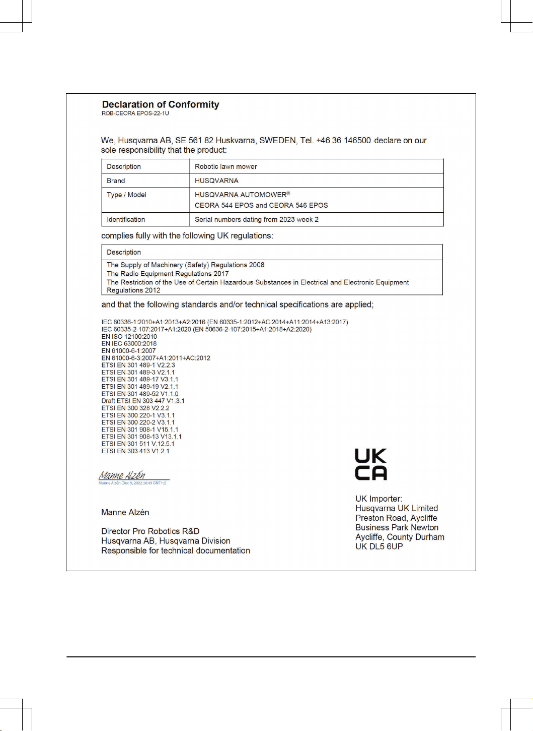
10.3 Original UK Declaration of Conformity
1691 - 007 - 22.12.2023 Declaration of Conformity -
59
Copyright © 2024 Husqvarna AB (publ.) All rights reserved.
Husqvarna and other product and feature marks are trademarks of Husqvarna Group.
www.husqvarna.com
Original instructions
1143611-26
2024-01-10

