Install / Use & Care
MANUAL
Undercounter Nugget Ice Machine
FNIU515D
TABLE OF CONTENTS
Tip: Click on any section below to jump directly there
Safety
Important Safety Instructions
Installation
Unpacking Your Appliance
Electrical
Cutout & Product Dimensions
Installing Your Appliance
Door Reversal
Installing The Water Supply
Installing the Drain plumbing
Maintenance
Care and Cleaning
Operating Instructions
Using Your Electronic Control
Ice Maker Operation
Service
Troubleshooting
Wire Diagram
Product Liability
R600a Specifications
Compressor Specifications
Service Information
Warranty
2
IMPORTANT SAFETY INSTRUCTIONS
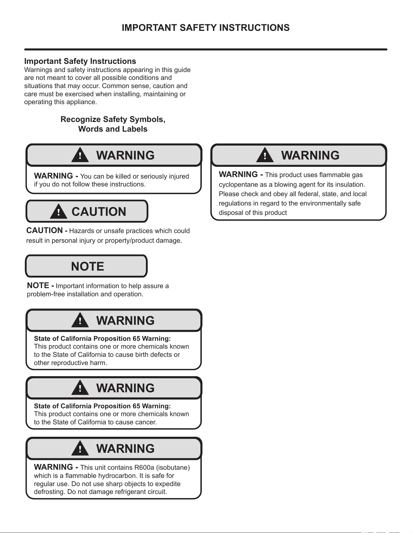
Important Safety Instructions
Warnings and safety instructions appearing in this guide
are not meant to cover all possible conditions and
situations that may occur. Common sense, caution and
care must be exercised when installing, maintaining or
operating this appliance.
Recognize Safety Symbols,
Words and Labels
!
WARNING
WARNING - You can be killed or seriously injured
if you do not follow these instructions.
!
CAUTION
CAUTION - Hazards or unsafe practices which could
result in personal injury or property/product damage.
NOTE
NOTE - Important information to help assure a
problem-free installation and operation.
!
WARNING
State of California Proposition 65 Warning:
This product contains one or more chemicals known
to the State of California to cause birth defects or
other reproductive harm.
!
WARNING
State of California Proposition 65 Warning:
This product contains one or more chemicals known
to the State of California to cause cancer.
!
WARNING
WARNING - This unit contains R600a (isobutane)
which is a ammable hydrocarbon. It is safe for
regular use. Do not use sharp objects to expedite
defrosting. Do not damage refrigerant circuit.
!
WARNING
WARNING - This product uses ammable gas
cyclopentane as a blowing agent for its insulation.
Please check and obey all federal, state, and local
regulations in regard to the environmentally safe
disposal of this product
3
UNPACKING YOUR APPLIANCE
!
WARNING
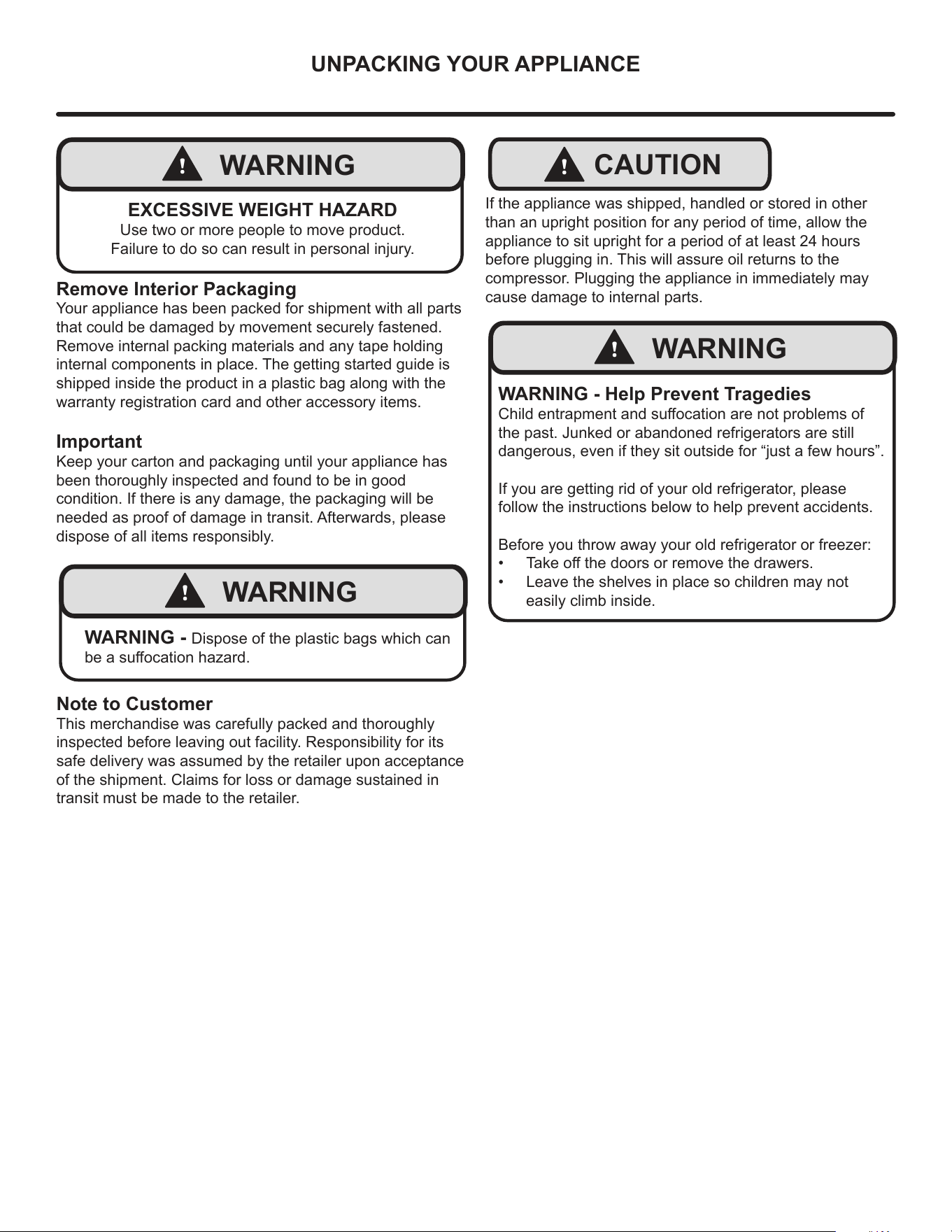
EXCESSIVE WEIGHT HAZARD
Use two or more people to move product.
Failure to do so can result in personal injury.
Remove Interior Packaging
Your appliance has been packed for shipment with all parts
that could be damaged by movement securely fastened.
Remove internal packing materials and any tape holding
internal components in place. The getting started guide is
shipped inside the product in a plastic bag along with the
warranty registration card and other accessory items.
Important
Keep your carton and packaging until your appliance has
been thoroughly inspected and found to be in good
condition. If there is any damage, the packaging will be
needed as proof of damage in transit. Afterwards, please
dispose of all items responsibly.
!
WARNING
WARNING - Dispose of the plastic bags which can
be a suocation hazard.
Note to Customer
This merchandise was carefully packed and thoroughly
inspected before leaving out facility. Responsibility for its
safe delivery was assumed by the retailer upon acceptance
of the shipment. Claims for loss or damage sustained in
transit must be made to the retailer.
!
CAUTION
If the appliance was shipped, handled or stored in other
than an upright position for any period of time, allow the
appliance to sit upright for a period of at least 24 hours
before plugging in. This will assure oil returns to the
compressor. Plugging the appliance in immediately may
cause damage to internal parts.
!
WARNING
WARNING - Help Prevent Tragedies
Child entrapment and suocation are not problems of
the past. Junked or abandoned refrigerators are still
dangerous, even if they sit outside for “just a few hours”.
If you are getting rid of your old refrigerator, please
follow the instructions below to help prevent accidents.
Before you throw away your old refrigerator or freezer:
• Take o the doors or remove the drawers.
• Leave the shelves in place so children may not
easily climb inside.
4
ELECTRICAL
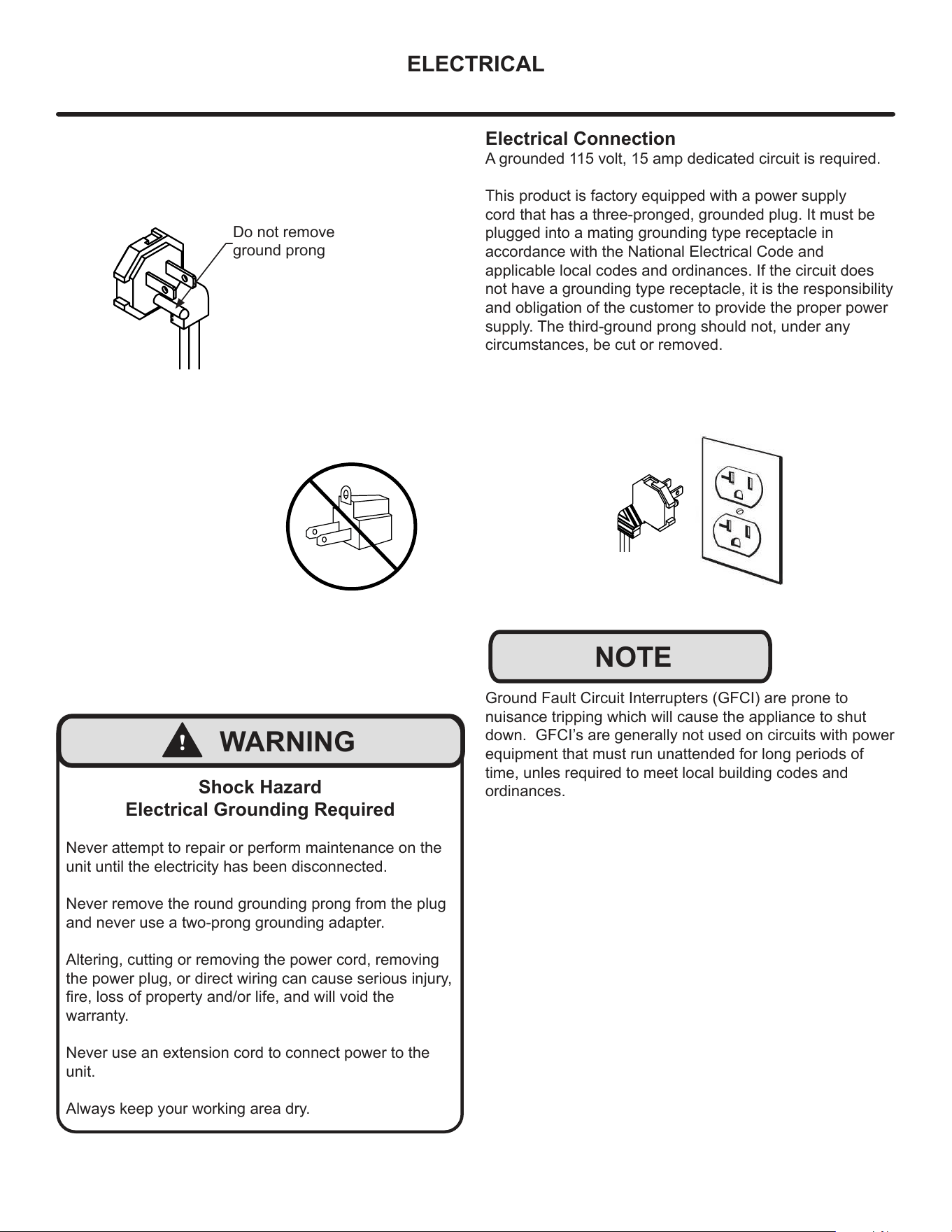
Do not remove
ground prong
!
WARNING
Shock Hazard
Electrical Grounding Required
Never attempt to repair or perform maintenance on the
unit until the electricity has been disconnected.
Never remove the round grounding prong from the plug
and never use a two-prong grounding adapter.
Altering, cutting or removing the power cord, removing
the power plug, or direct wiring can cause serious injury,
re, loss of property and/or life, and will void the
warranty.
Never use an extension cord to connect power to the
unit.
Always keep your working area dry.
Electrical Connection
A grounded 115 volt, 15 amp dedicated circuit is required.
This product is factory equipped with a power supply
cord that has a three-pronged, grounded plug. It must be
plugged into a mating grounding type receptacle in
accordance with the National Electrical Code and
applicable local codes and ordinances. If the circuit does
not have a grounding type receptacle, it is the responsibility
and obligation of the customer to provide the proper power
supply. The third-ground prong should not, under any
circumstances, be cut or removed.
NOTE
Ground Fault Circuit Interrupters (GFCI) are prone to
nuisance tripping which will cause the appliance to shut
down. GFCI’s are generally not used on circuits with power
equipment that must run unattended for long periods of
time, unles required to meet local building codes and
ordinances.
5
CUTOUT & PRODUCT DIMENSIONS
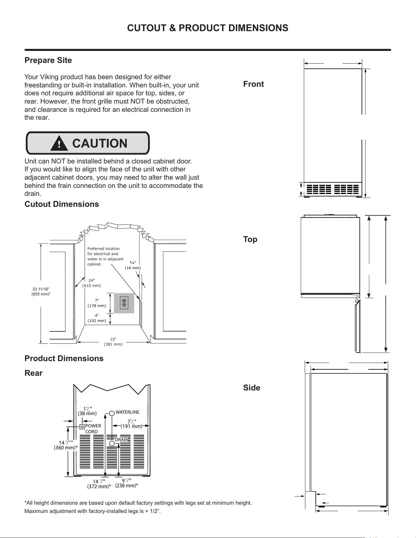
Prepare Site
Your Viking product has been designed for either
freestanding or built-in installation. When built-in, your unit
does not require additional air space for top, sides, or
rear. However, the front grille must NOT be obstructed,
and clearance is required for an electrical connection in
the rear.
!
CAUTION
Unit can NOT be installed behind a closed cabinet door.
If you would like to align the face of the unit with other
adjacent cabinet doors, you may need to alter the wall just
behind the frain connection on the unit to accommodate the
drain.
Cutout Dimensions
Product Dimensions
Rear
Front
Top
Side
4"
(102 mm)
7"
(178 mm)
15"
(381 mm)
Preferred location
for electrical and
water is in adjacent
cabinet.
24"
(610 mm)
5⁄8"
(16 mm)
33 ˜˜⁄˛˝”
(855 mm˙*
33 11/16”
(855 mm)*
1˜⁄˛”
(38 mm)
7˜⁄˛”
(191 mm)
WATERLINE
DRAIN
POWER
CORD
9 ˜⁄˝”
(238 mm)*
14 ˙⁄˝”
(372 mm)*
14 ˆ⁄ˇ˘”
(360 mm)*
MRNP
*All height dimensions are based upon default factory settings with legs set at minimum height.
Maximum adjustment with factory-installed legs is + 1/2”.
14 ˜⁄˛”
(378 mm)
33 ˝˝⁄˙ˆ”
(855 mmˇ
to
˝⁄˛”34
(867 mmˇ
3”
(76 mm)
22 1/4”
(565 mm)
38 13/16”
(960 mm)
6
19”
(483 mm)
3 ˜⁄˛”
(82 mm)
(565 mm)
20 ˝⁄˙ˆ”
(518 mm)
22 ˜⁄˛”
INSTALLING YOUR APPLIANCE
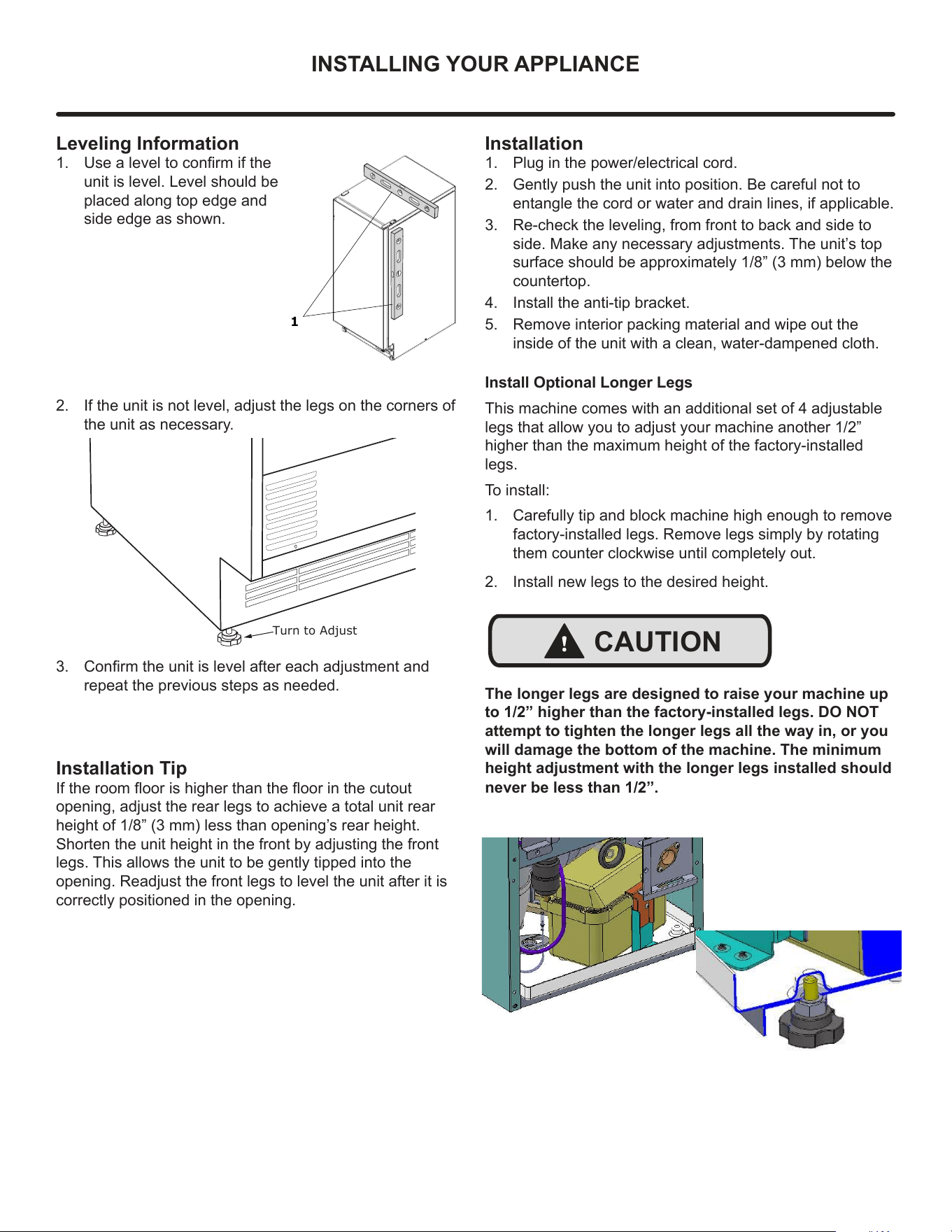
Leveling Information
1. Use a level to conrm if the
unit is level. Level should be
placed along top edge and
side edge as shown.
2. If the unit is not level, adjust the legs on the corners of
the unit as necessary.
3. Conrm the unit is level after each adjustment and
repeat the previous steps as needed.
1
Installation Tip
If the room oor is higher than the oor in the cutout
opening, adjust the rear legs to achieve a total unit rear
height of 1/8” (3 mm) less than opening’s rear height.
Shorten the unit height in the front by adjusting the front
legs. This allows the unit to be gently tipped into the
opening. Readjust the front legs to level the unit after it is
correctly positioned in the opening.
Installation
1. Plug in the power/electrical cord.
2. Gently push the unit into position. Be careful not to
entangle the cord or water and drain lines, if applicable.
3. Re-check the leveling, from front to back and side to
side. Make any necessary adjustments. The unit’s top
surface should be approximately 1/8” (3 mm) below the
countertop.
4. Install the anti-tip bracket.
5. Remove interior packing material and wipe out the
inside of the unit with a clean, water-dampened cloth.
Turn to Adjust
Install Optional Longer Legs
This machine comes with an additional set of 4 adjustable
legs that allow you to adjust your machine another 1/2”
higher than the maximum height of the factory-installed
legs.
To install:
1. Carefully tip and block machine high enough to remove
factory-installed legs. Remove legs simply by rotating
them counter clockwise until completely out.
2. Install new legs to the desired height.
The longer legs are designed to raise your machine up
to 1/2” higher than the factory-installed legs. DO NOT
attempt to tighten the longer legs all the way in, or you
will damage the bottom of the machine. The minimum
height adjustment with the longer legs installed should
!
CAUTION
never be less than 1/2”.
7
DOOR REVERSAL
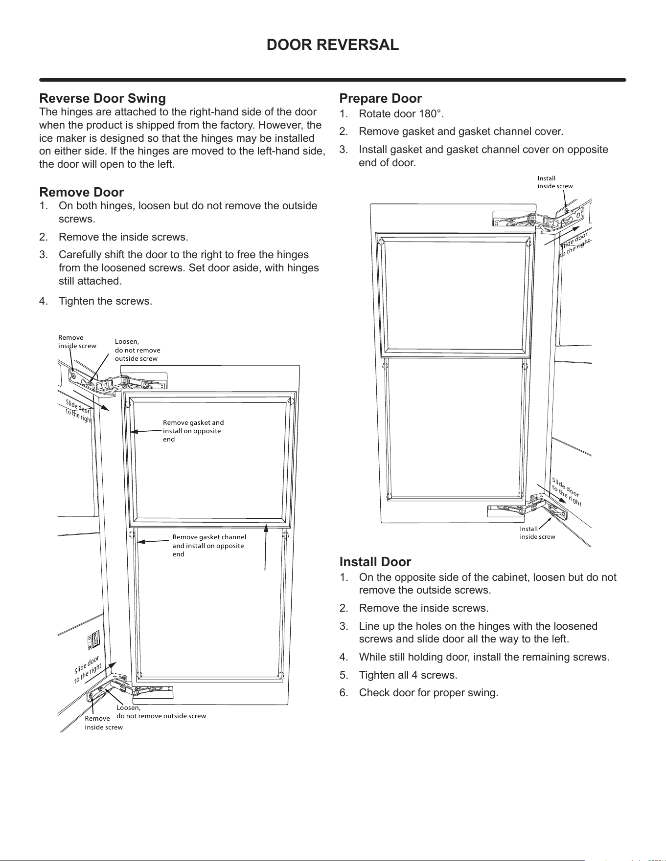
Reverse Door Swing
The hinges are attached to the right-hand side of the door
when the product is shipped from the factory. However, the
ice maker is designed so that the hinges may be installed
on either side. If the hinges are moved to the left-hand side,
the door will open to the left.
Remove Door
1. On both hinges, loosen but do not remove the outside
screws.
2. Remove the inside screws.
3. Carefully shift the door to the right to free the hinges
from the loosened screws. Set door aside, with hinges
still attached.
4. Tighten the screws.
Remove gasket and
install on opposite
end
Remove gasket channel
and install on opposite
end
OFF
Remove
inside screw
Remove
inside screw
Loosen,
do not remove
outside screw
Loosen,
do not remove outside screw
Slide door
to the right
Slide door
to the right
Install
inside screw
Install
inside screw
Slide door
to the right
Slide door
to the right
Prepare Door
1. Rotate door 180°.
2. Remove gasket and gasket channel cover.
3. Install gasket and gasket channel cover on opposite
end of door.
Install Door
1. On the opposite side of the cabinet, loosen but do not
remove the outside screws.
2. Remove the inside screws.
3. Line up the holes on the hinges with the loosened
screws and slide door all the way to the left.
4. While still holding door, install the remaining screws.
5. Tighten all 4 screws.
6. Check door for proper swing.
8
USING YOUR ELECTRONIC CONTROL
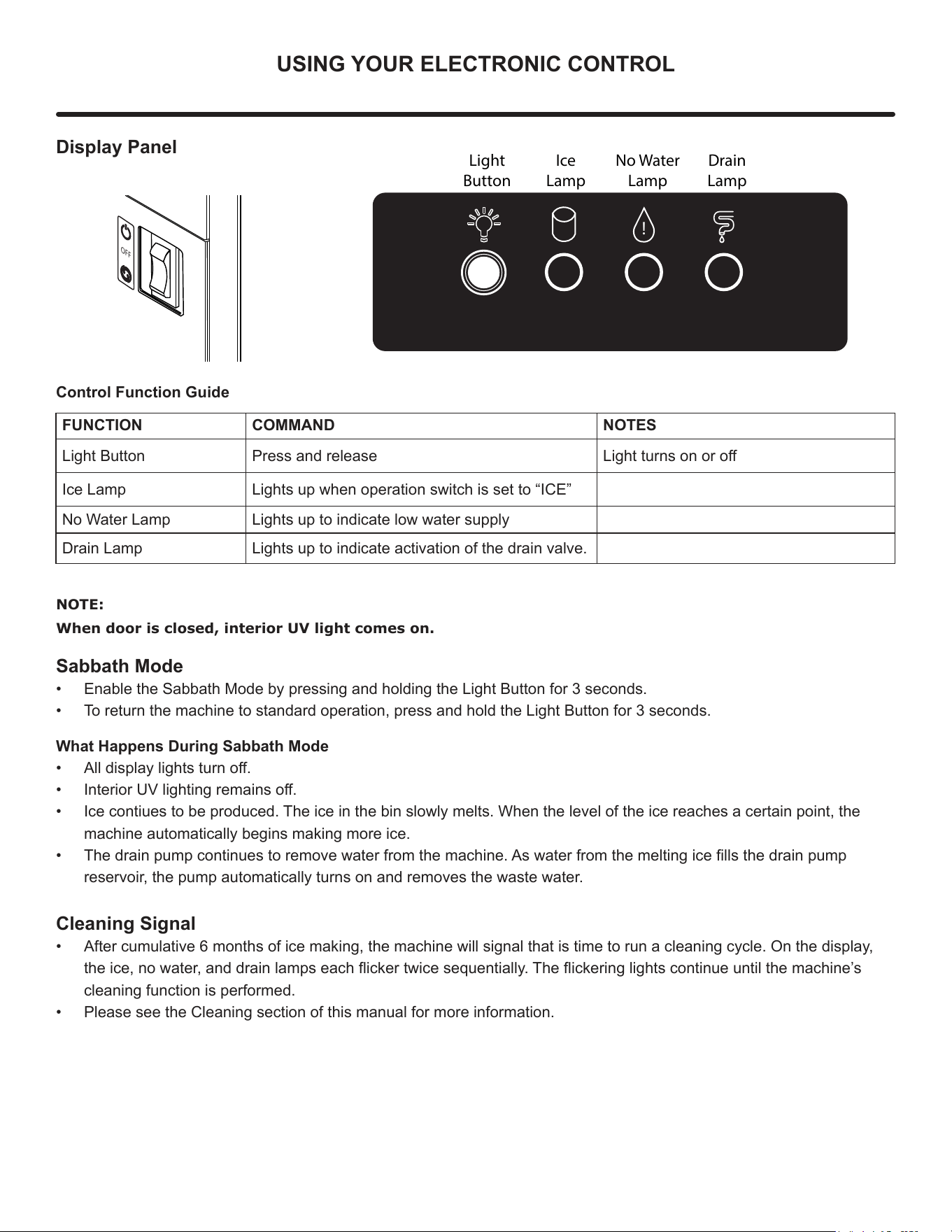
Display Panel
Control Function Guide
FUNCTION COMMAND NOTES
Light Button Press and release Light turns on or o
Ice Lamp Lights up when operation switch is set to “ICE”
No Water Lamp Lights up to indicate low water supply
Drain Lamp Lights up to indicate activation of the drain valve.
OFF
!
Light
Button
Ice
Lamp
No Water
Lamp
Drain
Lamp
NOTE:
When door is closed, interior UV light comes on.
Sabbath Mode
• Enable the Sabbath Mode by pressing and holding the Light Button for 3 seconds.
• To return the machine to standard operation, press and hold the Light Button for 3 seconds.
What Happens During Sabbath Mode
• All display lights turn o.
• Interior UV lighting remains o.
• Ice contiues to be produced. The ice in the bin slowly melts. When the level of the ice reaches a certain point, the
machine automatically begins making more ice.
• The drain pump continues to remove water from the machine. As water from the melting ice lls the drain pump
reservoir, the pump automatically turns on and removes the waste water.
Cleaning Signal
• After cumulative 6 months of ice making, the machine will signal that is time to run a cleaning cycle. On the display,
the ice, no water, and drain lamps each icker twice sequentially. The ickering lights continue until the machine’s
cleaning function is performed.
• Please see the Cleaning section of this manual for more information.
9
INSTALLING THE WATER SUPPLY
Water Hookup
Prepare Plumbing
Plan the arrangement of the water supply pipes.
Connect a 1/4” diameter copper waterline to the tap water
supply line. Install a shuto valve between the tap water
pipe and the product so that the user can operate the valve.
Do not install the shuto valve at the back of the product.
“Do not use a self-piercing valve. If the tap water has a high
level of minerals, a pipeline lter will be required.
The pressure of the tap water should be maintained at a
level between 20psi (1.4bar) and 80psi (5.5bar).
Plumbing installation must observe all state and local
codes. All water and drain connections MUST BE made by
a licensed/qualied plumbing contractor. Failure to follow
recommendations and instructions may result in damage
and/or harm.
Water Supply Connection
When connecting the water supply, please note the
following:
• Before installing the unit and connecting to the cold
water supply, review the local plumbing codes.
• Water has less than 400 mg/L (ppm) total dissolved
solids and hardness level below 200 mg/L (ppm) — i.e.,
below 12 grains per gallon. Check by using TDS meter
or consulting with local water company.
• Softened water is not recommended as it may result in
softer ice than desired.
• Connection to the water main is made with hose-set
only.
• Hose-set must be new, not reused, and in compliance
with IEC 61770.
• The water line MUST have a shut-o valve in the
supply line.
• The water line should be looped into 2 coils. This will
allow the unit to be removed for cleaning and servicing.
Make certain that the tubing is not pinched or damaged
during installation.
Do not use any plastic water supply line. The line is under
pressure at all times. Plastic may crack or rupture with age
and cause damage to your home.
!
CAUTION
!
CAUTION
Do not use tape or joint compound when attaching a
braided exible water supply line that includes a rubber
gasket. The gasket provides an adequate seal – other
materials could cause blockage of the valve.
Failure to follow recommendations and instructions may
result in damage and/or harm, ooding or void the product
warranty.
Use new hose set. Do not reuse old hose set.
Turn o water supply and disconnect electrical supply to
unit prior to installation.
Use caution when handling back panel. The edges could
be sharp.
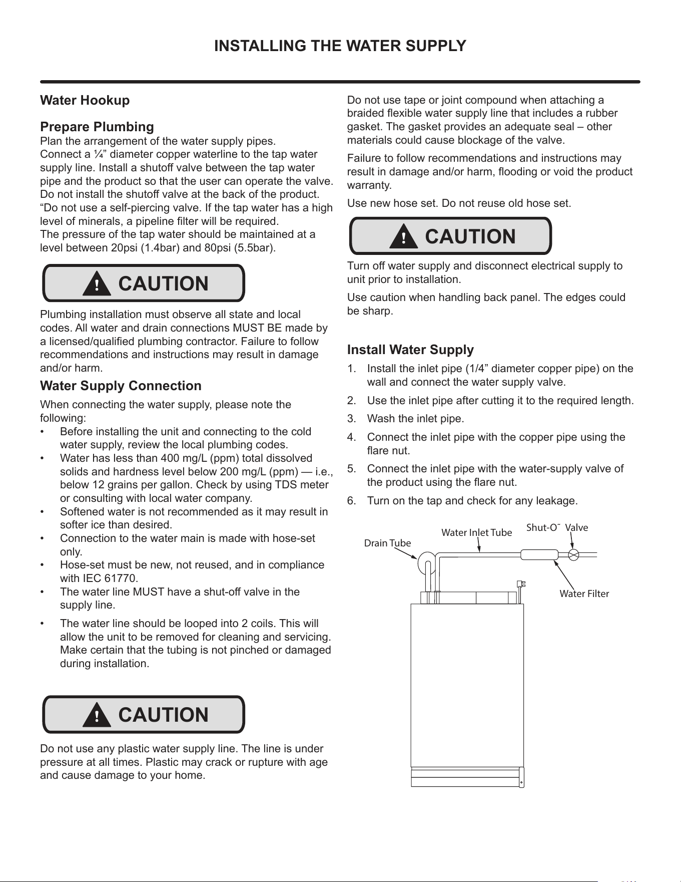
Install Water Supply
1. Install the inlet pipe (1/4” diameter copper pipe) on the
wall and connect the water supply valve.
2. Use the inlet pipe after cutting it to the required length.
3. Wash the inlet pipe.
4. Connect the inlet pipe with the copper pipe using the
are nut.
5. Connect the inlet pipe with the water-supply valve of
the product using the are nut.
6. Turn on the tap and check for any leakage.
Shut-O˜ Valve
Water Filter
Drain Tube
Water Inlet Tube
!
CAUTION
10
INSTALLING THE DRAIN PLUMBING
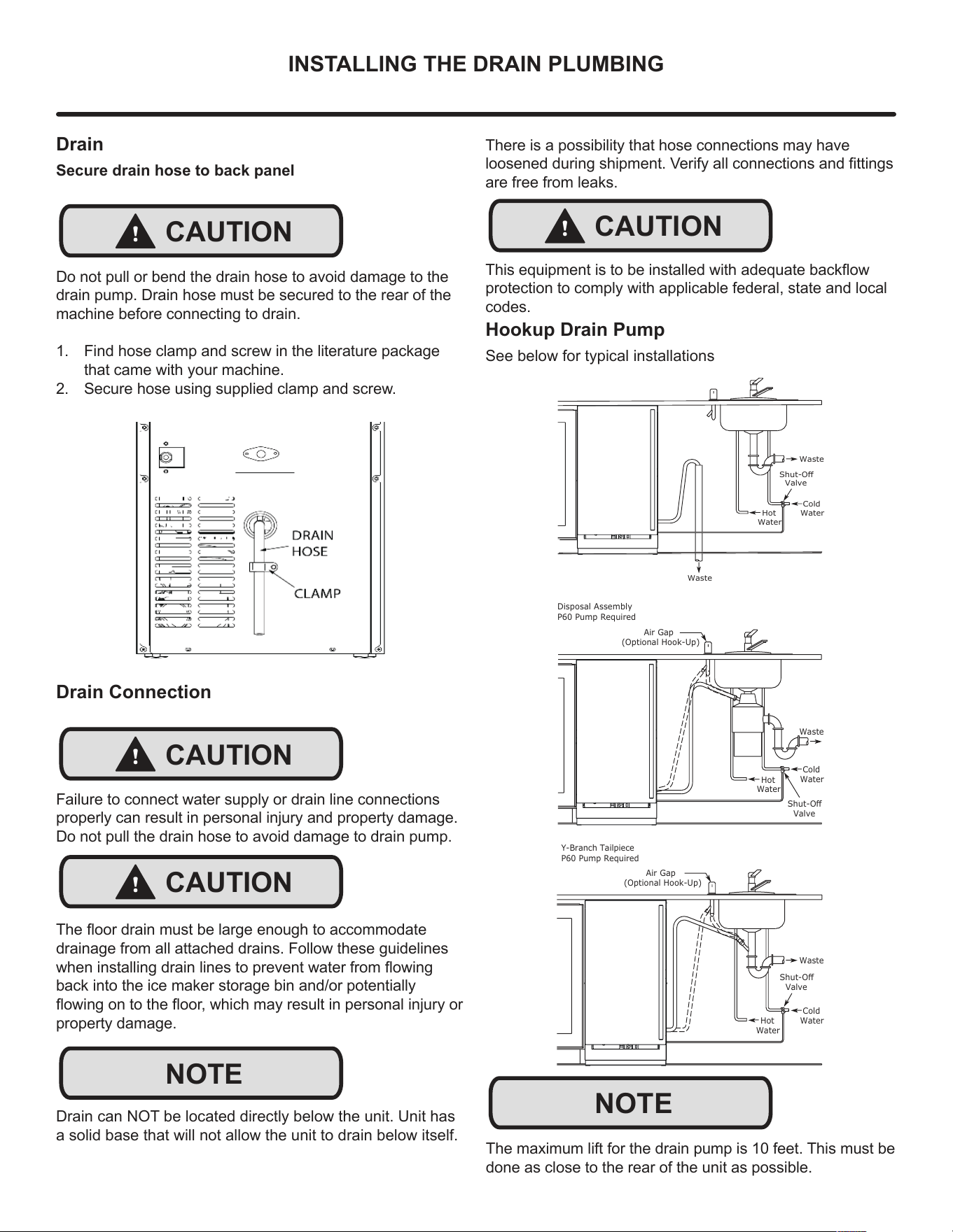
Drain
Secure drain hose to back panel
Do not pull or bend the drain hose to avoid damage to the
drain pump. Drain hose must be secured to the rear of the
machine before connecting to drain.
1. Find hose clamp and screw in the literature package
that came with your machine.
2. Secure hose using supplied clamp and screw.
!
CAUTION
NOTE
Cold
Water
Hot
Water
Waste
Waste
Shut-Off
Valve
Air Gap
(Optional Hook-Up)
Cold
Water
Hot
Water
Waste
Shut-Off
Valve
Disposal Assembly
P60 Pump Required
Waste
Cold
Water
Shut-Off
Valve
Hot
Water
Air Gap
(Optional Hook-Up)
Y-Branch Tailpiece
P60 Pump Required
There is a possibility that hose connections may have
loosened during shipment. Verify all connections and ttings
are free from leaks.
Drain Connection
Failure to connect water supply or drain line connections
properly can result in personal injury and property damage.
Do not pull the drain hose to avoid damage to drain pump.
The oor drain must be large enough to accommodate
drainage from all attached drains. Follow these guidelines
when installing drain lines to prevent water from owing
back into the ice maker storage bin and/or potentially
owing on to the oor, which may result in personal injury or
property damage.
Drain can NOT be located directly below the unit. Unit has
a solid base that will not allow the unit to drain below itself.
!
CAUTION
!
CAUTION
NOTE
!
CAUTION
This equipment is to be installed with adequate backow
protection to comply with applicable federal, state and local
codes.
Hookup Drain Pump
See below for typical installations
The maximum lift for the drain pump is 10 feet. This must be
done as close to the rear of the unit as possible.
11
ICE MAKER OPERATION
Ice
Do not put anything other than ice in the ice bin. Wine or
beer bottles are unsanitary and a detached label may block
the drain.
If the ice storage bin is full of water, turn o the ice maker
and clean the mesh on the bottom of the ice bin.
Ice-Making Process
Water ows into the drum, and as the auger rotates, the
water freezes and is ejected upward. Impurities in the water
are periodically discharged by the drain valve to create
clean ice.
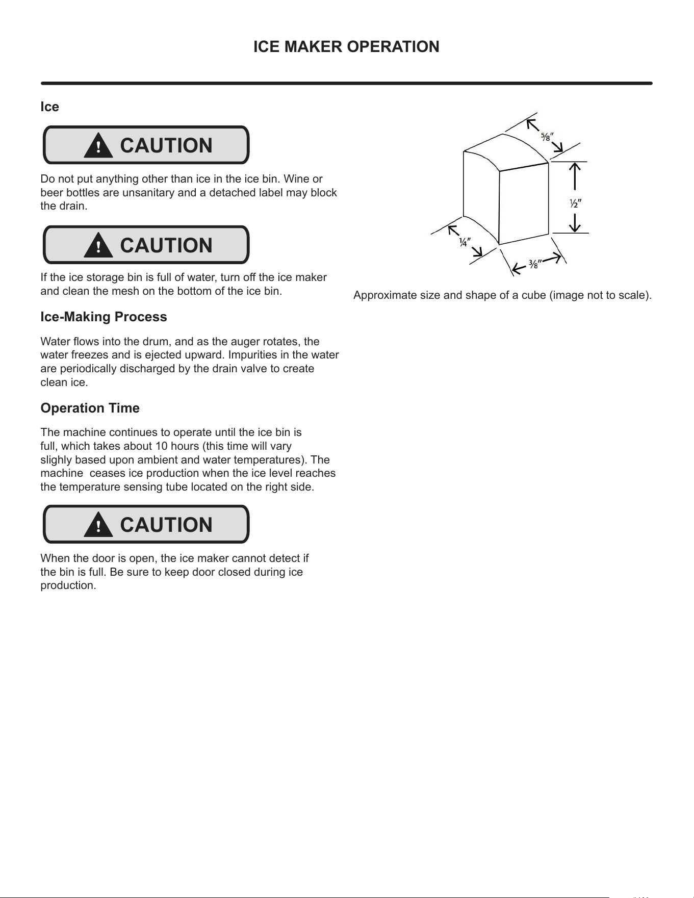
Operation Time
The machine continues to operate until the ice bin is
full, which takes about 10 hours (this time will vary
slighly based upon ambient and water temperatures). The
machine ceases ice production when the ice level reaches
the temperature sensing tube located on the right side.
When the door is open, the ice maker cannot detect if
the bin is full. Be sure to keep door closed during ice
production.
!
CAUTION
!
CAUTION
!
CAUTION
Approximate size and shape of a cube (image not to scale).
12
CARE & CLEANING
Cleaning
Use only Viking Ice Machine Cleaner, available for
purchase from vikingrange.com or your dealer. It is a
violation of federal law to use this solution in a
manner inconsistent with its labeling. Use of any other
cleaner can cause damage to the ice ma-chine and
will void the warranty. Read and understand all labels
printed on the package before use.
Viking Ice Machine Cleaner is used to remove lime
scale and other mineral deposits. Refer to the
following steps to initiate the self-cleaning cycle.
Internal Cleaning
Cleaning Signal
• After cumulative 6 months of ice making, the machine
will signal that is time to run a cleaning cycle. On the
display, the ice, no water, and drain lamps each icker
twice sequentially. The ickering lights continue until
the machine’s cleaning function is performed.
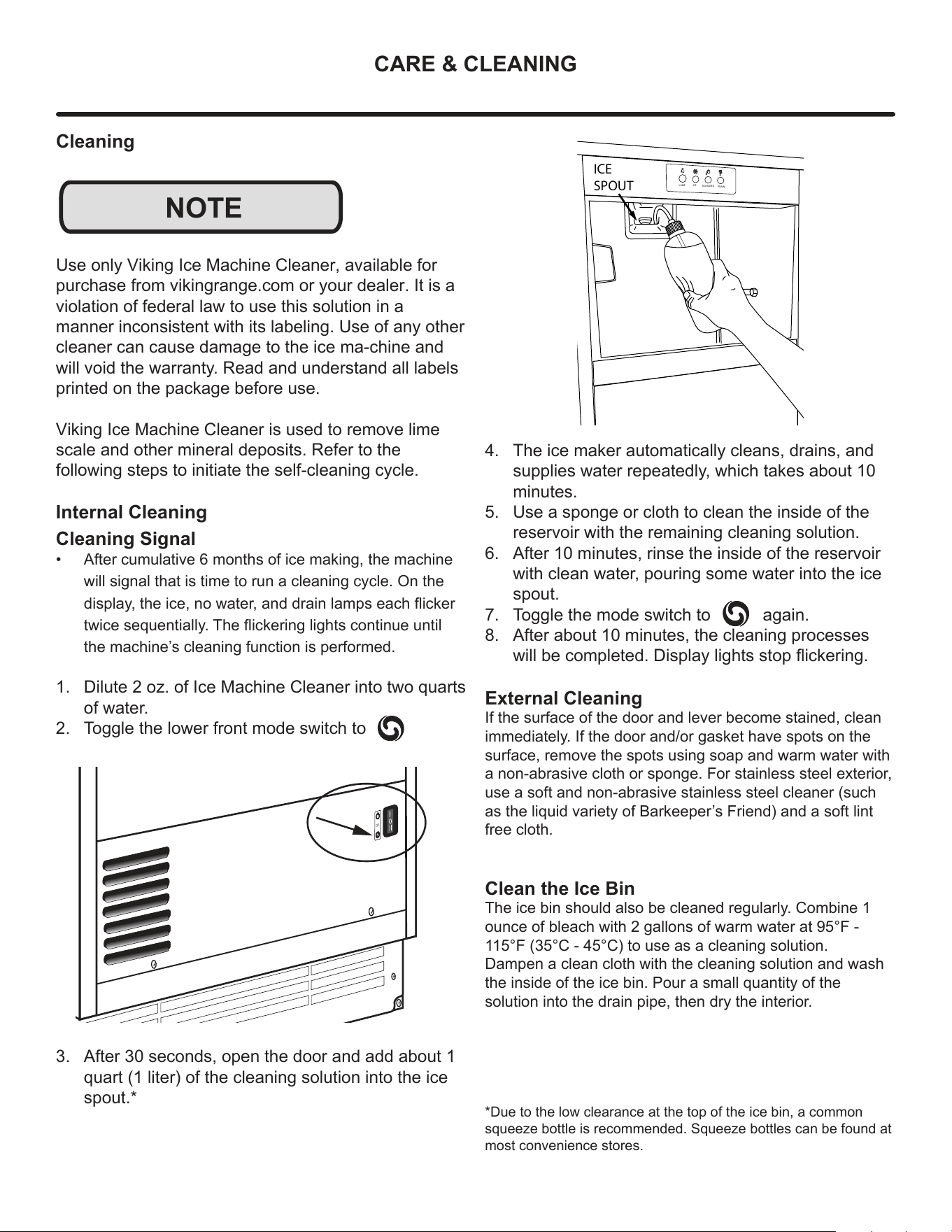
1. Dilute 2 oz. of Ice Machine Cleaner into two quarts
of water.
2. Toggle the lower front mode switch to
3. After 30 seconds, open the door and add about 1
quart (1 liter) of the cleaning solution into the ice
spout.*
NOTE
OFF
4. The ice maker automatically cleans, drains, and
supplies water repeatedly, which takes about 10
minutes.
5. Use a sponge or cloth to clean the inside of the
reservoir with the remaining cleaning solution.
6. After 10 minutes, rinse the inside of the reservoir
with clean water, pouring some water into the ice
spout.
7. Toggle the mode switch to again.
8. After about 10 minutes, the cleaning processes
will be completed. Display lights stop ickering.
External Cleaning
If the surface of the door and lever become stained, clean
immediately. If the door and/or gasket have spots on the
surface, remove the spots using soap and warm water with
a non-abrasive cloth or sponge. For stainless steel exterior,
use a soft and non-abrasive stainless steel cleaner (such
as the liquid variety of Barkeeper’s Friend) and a soft lint
free cloth.
Clean the Ice Bin
The ice bin should also be cleaned regularly. Combine 1
ounce of bleach with 2 gallons of warm water at 95°F -
115°F (35°C - 45°C) to use as a cleaning solution.
Dampen a clean cloth with the cleaning solution and wash
the inside of the ice bin. Pour a small quantity of the
solution into the drain pipe, then dry the interior.
*Due to the low clearance at the top of the ice bin, a common
squeeze bottle is recommended. Squeeze bottles can be found at
most convenience stores.
LAMP
ICE
NO WATER
DRAIN
ICE
SPOUT
13
CARE & CLEANING
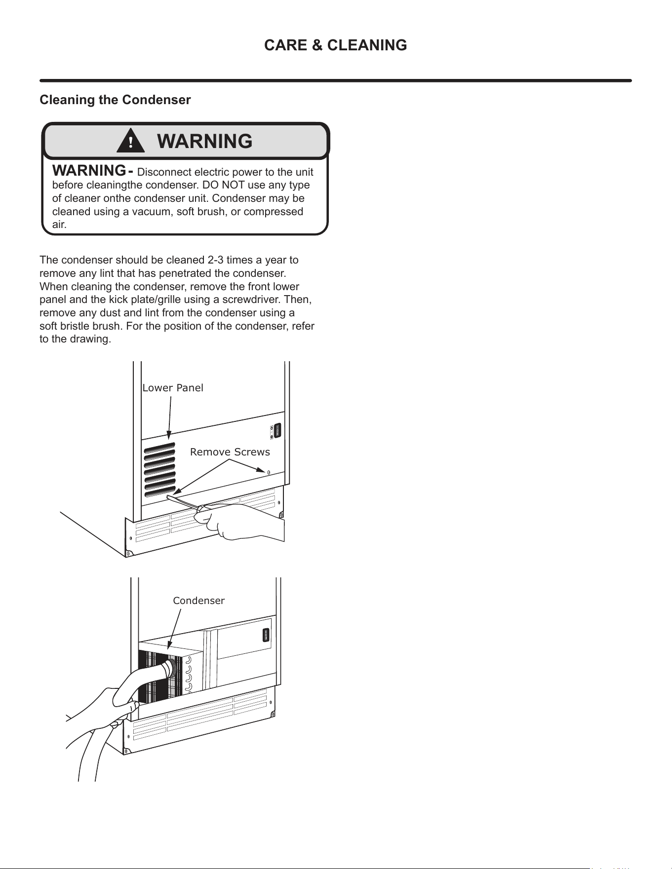
Cleaning the Condenser
The condenser should be cleaned 2-3 times a year to
remove any lint that has penetrated the condenser.
When cleaning the condenser, remove the front lower
panel and the kick plate/grille using a screwdriver. Then,
remove any dust and lint from the condenser using a
soft bristle brush. For the position of the condenser, refer
to the drawing.
OFF
Remove Screws
Lower Panel
Condenser
!
WARNING
WARNING - Disconnect electric power to the unit
before cleaningthe condenser. DO NOT use any type
of cleaner onthe condenser unit. Condenser may be
cleaned using a vacuum, soft brush, or compressed
air.
14
TROUBLESHOOTING
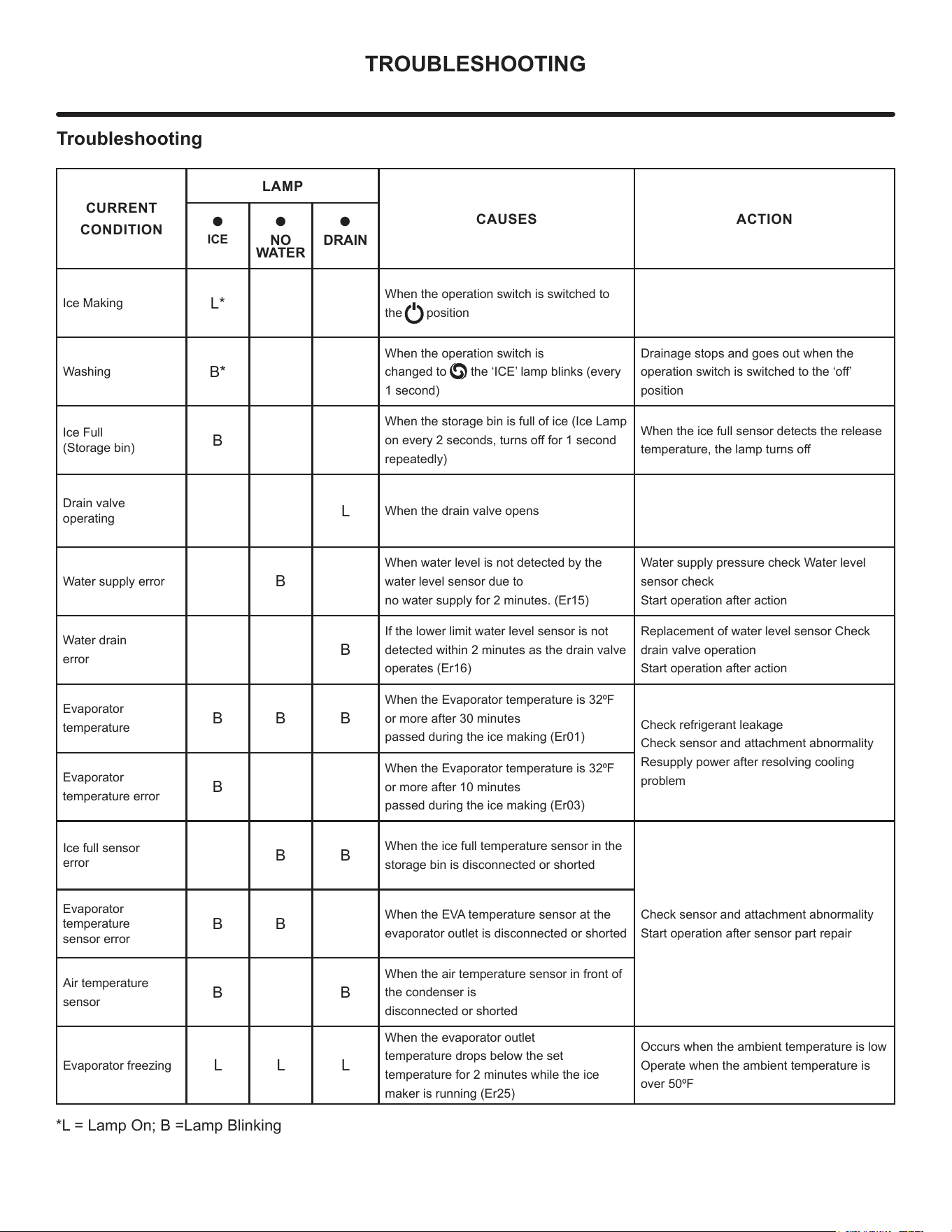
Troubleshooting
CURRENT
CONDITION
LAMP
CAUSES ACTION
•
ICE
•
NO
WATER
•
DRAIN
Ice Making
L*
When the operation switch is switched to
the position
Washing
B*
When the operation switch is
changed to , the ‘ICE’ lamp blinks (every
1 second)
Drainage stops and goes out when the
operation switch is switched to the ‘o’
position
Ice Full
(Storage bin)
B
When the storage bin is full of ice (Ice Lamp
on every 2 seconds, turns o for 1 second
repeatedly)
When the ice full sensor detects the release
temperature, the lamp turns o
Drain valve
operating
L
When the drain valve opens
Water supply error
B
When water level is not detected by the
water level sensor due to
no water supply for 2 minutes. (Er15)
Water supply pressure check Water level
sensor check
Start operation after action
Water drain
error
B
If the lower limit water level sensor is not
detected within 2 minutes as the drain valve
operates (Er16)
Replacement of water level sensor Check
drain valve operation
Start operation after action
Evaporator
temperature
B B B
When the Evaporator temperature is 320F
or more after 30 minutes
passed during the ice making (Er01)
Check refrigerant leakage
Check sensor and attachment abnormality
Resupply power after resolving cooling
problem
Evaporator
temperature error
B
When the Evaporator temperature is 320F
or more after 10 minutes
passed during the ice making (Er03)
Ice full sensor
error
B B
When the ice full temperature sensor in the
storage bin is disconnected or shorted
Check sensor and attachment abnormality
Start operation after sensor part repair
Evaporator
temperature
sensor error
B B
When the EVA temperature sensor at the
evaporator outlet is disconnected or shorted
Air temperature
sensor
B B
When the air temperature sensor in front of
the condenser is
disconnected or shorted
Evaporator freezing
L L L
When the evaporator outlet
temperature drops below the set
temperature for 2 minutes while the ice
maker is running (Er25)
Occurs when the ambient temperature is low
Operate when the ambient temperature is
over 500F
*L = Lamp On; B =Lamp Blinking
15
TROUBLESHOOTING
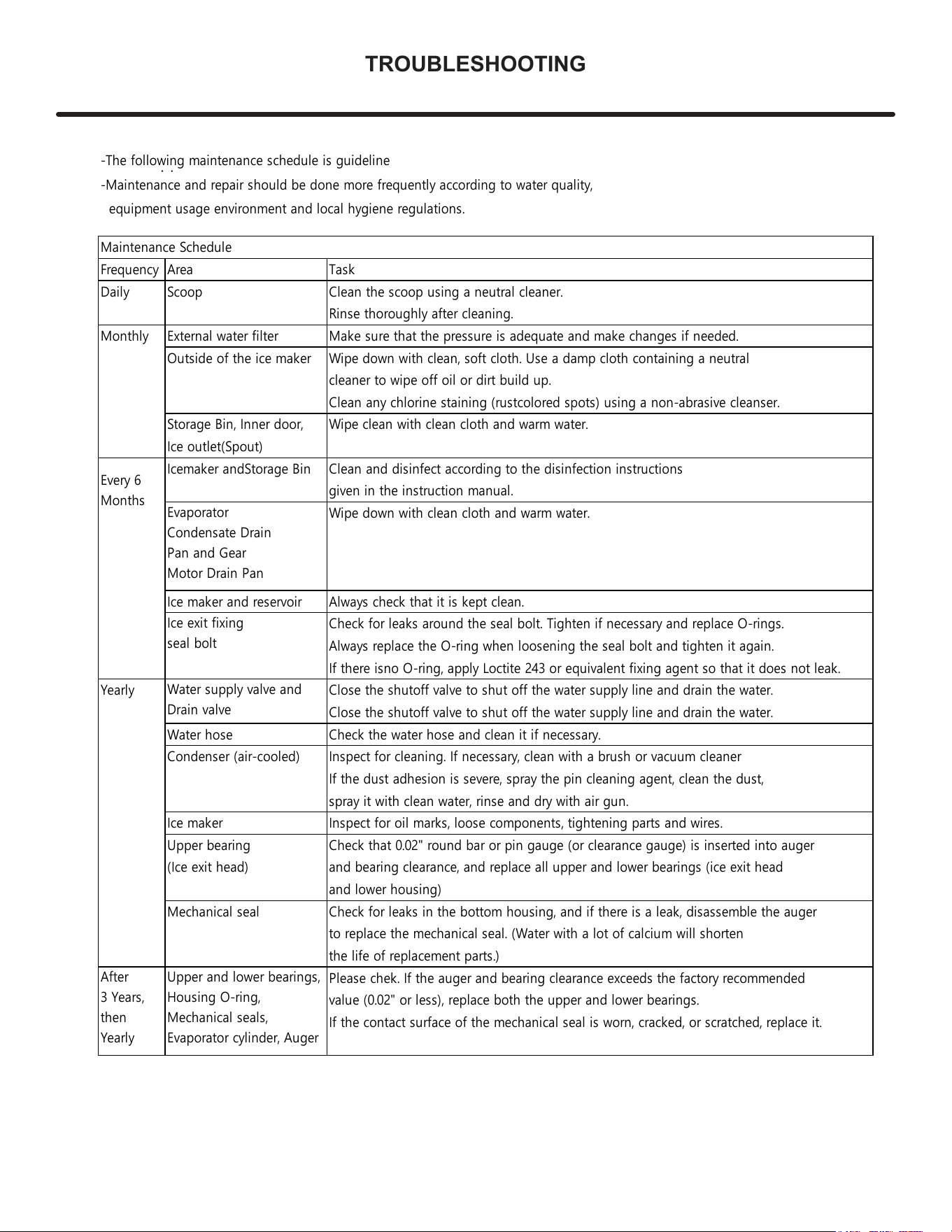
-The following maintenance schedule is guideline
-Maintenance and repair should be done more frequently according to water quality,
equipment usage environment and local hygiene regulations.
Maintenance Schedule
Frequency Area Task
Daily Scoop Clean the scoop using a neutral cleaner.
Rinse thoroughly after cleaning.
Monthly External water filter Make sure that the pressure is adequate and make changes if needed.
Outside of the ice maker
Wipe down with clean, soft cloth. Use a damp cloth containing a neutral
cleaner to wipe off oil or dirt build up.
Clean any chlorine staining (rust colored spots) using a non-abrasive cleanser.
Storage Bin, Inner door, Wipe clean with clean cloth and warm water.
Ice outlet(Spout)
Icemaker and Storage Bin Clean and disinfect according to the disinfection instructions
given in the instruction manual.
Wipe down with clean cloth and warm water.
Ice maker and reservoir Always check that it is kept clean.
Check for leaks around the seal bolt. Tighten if necessary and replace O-rings.
Always replace the O-ring when loosening the seal bolt and tighten it again.
If there is no O-ring, apply Loctite 243 or equivalent fixing agent so that it does not leak.
Yearly Close the shutoff valve to shut off the water supply line and drain the water.
Close the shutoff valve to shut off the water supply line and drain the water.
Water hose Check the water hose and clean it if necessary.
Condenser (air-cooled) Inspect for cleaning. If necessary, clean with a brush or vacuum cleaner
If the dust adhesion is severe, spray the pin cleaning agent, clean the dust,
spray it with clean water, rinse and dry with air gun.
Ice maker Inspect for oil marks, loose components, tightening parts and wires.
Upper bearing Check that 0.02" round bar or pin gauge (or clearance gauge) is inserted into auger
(Ice exit head) and bearing clearance, and replace all upper and lower bearings (ice exit head
and lower housing)
Mechanical seal Check for leaks in the bottom housing, and if there is a leak, disassemble the auger
to replace the mechanical seal. (Water with a lot of calcium will shorten
the life of replacement parts.)
Please chek. If the auger and bearing clearance exceeds the factory recommended
value (0.02" or less), replace both the upper and lower bearings.
If the contact surface of the mechanical seal is worn, cracked, or scratched, replace it.
Every 6
Months
After
3 Years,
then
Yearly
Evaporator
Condensate Drain
Pan and Gear
Motor Drain Pan
Ice exit fixing
seal bolt
Water supply valve and
Drain valve
Upper and lower bearings,
Housing O-ring,
Mechanical seals,
Evaporator cylinder, Auger
16
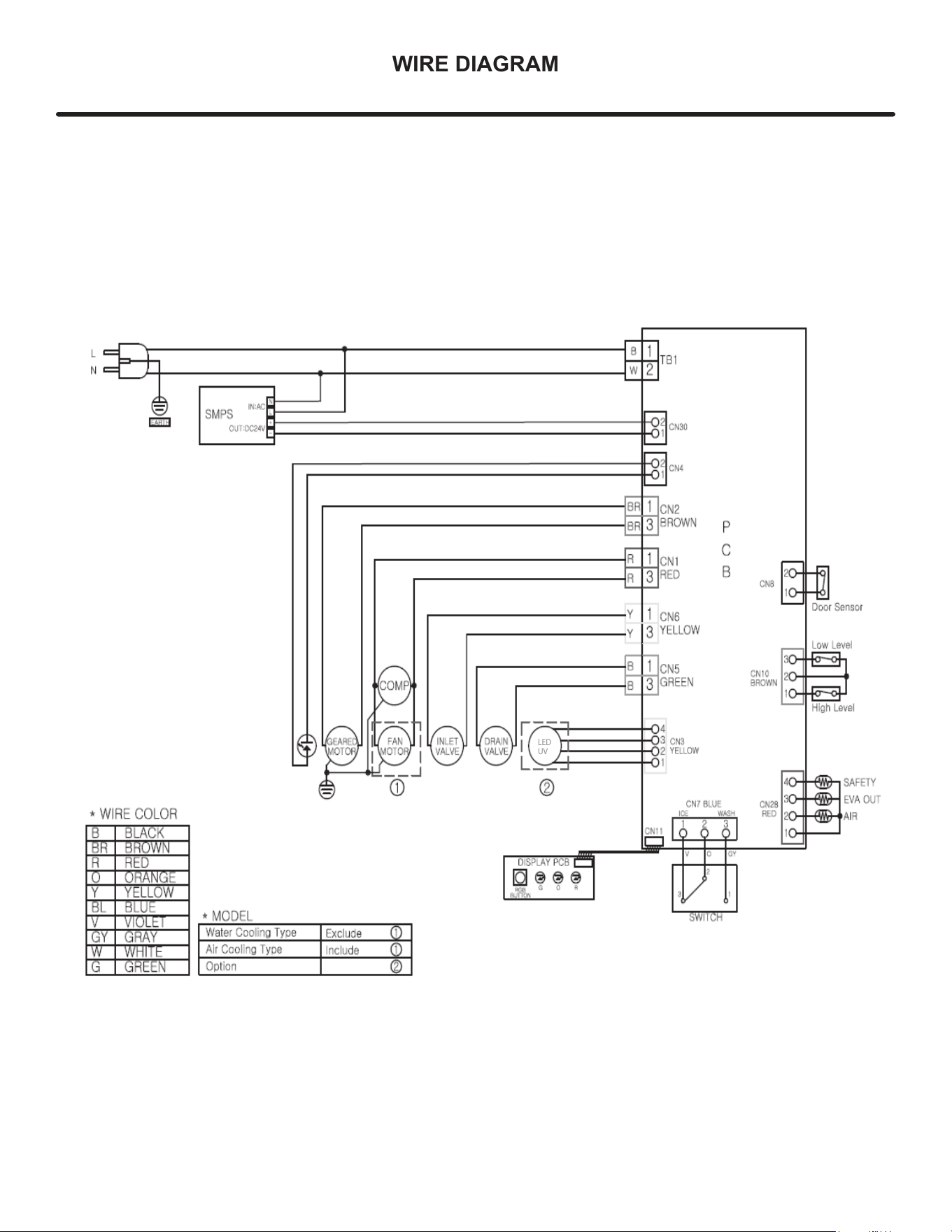
WIRE DIAGRAM
LED
UV
17
PRODUCT LIABILITY
Field service technicians are authorized to make an initial
assessment in the event of reported damages. If there are
any questions about the process involved, the technician
should call Viking for further explanation.
While inspecting for defects or installation issues, photos
should be taken to document any damages or issues
found.
During the assessment, if the service technician is able to
nd the source of the damage and it can be resolved by
replacement of a part, the servicer is authorized to replace
the part in question. The part that caused the damage must
be returned to Viking in its entirety. The part must be
clearly labeled with the serial number of the unit it was
removed from, the date, and the servicer who removed the
part.
If the service technician determines the damage is the
result of installation issues (water connection/drain, etc.),
the consumer would be notified and the issues shall be
resolved at the direction of the consumer.
If damage is evident and the service technician is
unable to find the source, Viking must be contacted at
(662) 455-1200 for further direction.
Viking Range, LLC
111 Front Street
Greenwood, Mississippi 38930 USA
(662) 455-1200
Website: www.vikingrange.com
18
R600A SPECIFICATIONS
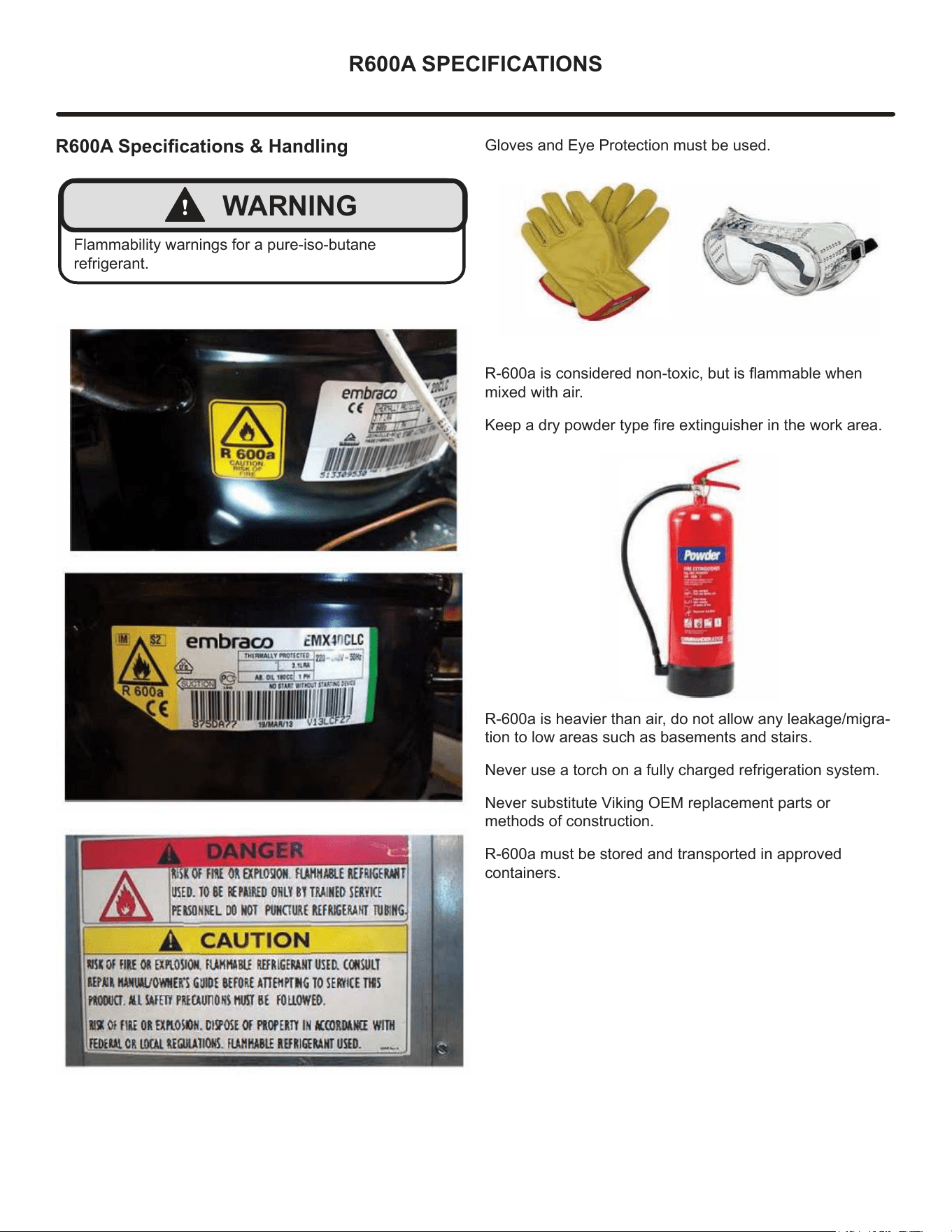
R600A Specications & Handling
!
WARNING
Flammability warnings for a pure-iso-butane
refrigerant.
Gloves and Eye Protection must be used.
R-600a is considered non-toxic, but is ammable when
mixed with air.
Keep a dry powder type re extinguisher in the work area.
R-600a is heavier than air, do not allow any leakage/migra-
tion to low areas such as basements and stairs.
Never use a torch on a fully charged refrigeration system.
Never substitute Viking OEM replacement parts or
methods of construction.
R-600a must be stored and transported in approved
containers.
19
R600A SPECIFICATIONS
!
WARNING
Only skilled and well trained service technicians
permitted to service R-600a equipped products.
All tools and equipment must be approved for use with
R-600a refrigerant.
Local, state and federal laws, standards must be
observed along with proper certication and licensing.
Ventilation is required during servicing.
No conversions to R-600a from any other refrigerants.
OEM R-600a equipped unit only.
Service area must be free of ignition sources.
No smoking is allowed in the service area.
All replacement electrical components must be OEM
and installed properly (sealed and covered).
If the evaporator is cold prior to service, it must be
thawed prior to service.
When using a vacuum pump, start pump before
opening refrigeration system.
Vacuum pump and recovery equipment should be at
least 10 feet from the work area.
It is recommended that a simple LPG gas detector is
on site during service.
Ensure that all R-600a is removed from the system
prior to brazing any part of the sealed system.
Only a clean, dry leak free system should be charged
with R-600a.
R-600A Specications/Labeling
R-600a equipped products are labeled (both the unit and
the compressor).
R-600a is colorless and odorless.
R-600a is considered non-toxic, but is ammable when
mixed with air.
Do not remove or alter any R-600a labeling on the product.
Use only a refrigerant grade R-600a from a properly
labeled container.
Recovering/Reclaiming R-600A
(R-600a has been exempted from recovery/reclaiming
requirements by the US EPA)
Recovery/Reclaiming equipment must be approved for use
with R-600a.
Ensure the evaporator is at room temperature prior to
recovery/reclaiming R-600a.
Use a common piercing pliers or piercing valve to remove
R-600a from the compressor process tube. (Note: Pierc-
ing devices must not be left on the system and must be
replaced with a Schrader type valve).
20
R600A SPECIFICATIONS
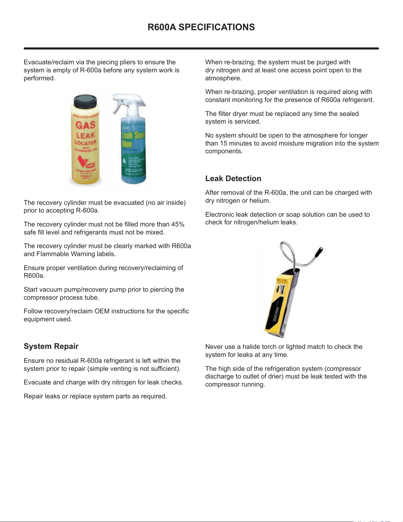
Evacuate/reclaim via the piecing pliers to ensure the
system is empty of R-600a before any system work is
performed.
The recovery cylinder must be evacuated (no air inside)
prior to accepting R-600a.
The recovery cylinder must not be lled more than 45%
safe ll level and refrigerants must not be mixed.
The recovery cylinder must be clearly marked with R600a
and Flammable Warning labels.
Ensure proper ventilation during recovery/reclaiming of
R600a.
Start vacuum pump/recovery pump prior to piercing the
compressor process tube.
Follow recovery/reclaim OEM instructions for the specic
equipment used.
System Repair
Ensure no residual R-600a refrigerant is left within the
system prior to repair (simple venting is not sucient).
Evacuate and charge with dry nitrogen for leak checks.
Repair leaks or replace system parts as required.
When re-brazing, the system must be purged with
dry nitrogen and at least one access point open to the
atmosphere.
When re-brazing, proper ventilation is required along with
constant monitoring for the presence of R600a refrigerant.
The lter dryer must be replaced any time the sealed
system is serviced.
No system should be open to the atmosphere for longer
than 15 minutes to avoid moisture migration into the system
components.
Leak Detection
After removal of the R-600a, the unit can be charged with
dry nitrogen or helium.
Electronic leak detection or soap solution can be used to
check for nitrogen/helium leaks.
Never use a halide torch or lighted match to check the
system for leaks at any time.
The high side of the refrigeration system (compressor
discharge to outlet of drier) must be leak tested with the
compressor running.
21

R600A SPECIFICATIONS
The low side of the refrigeration system (evaporator,
compressor and suction line) must be leak tested with the
compressor o (equalized pressure).
Recharging
No air is ever to be allowed inside the refrigeration system
(R-600a refrigerant or dry nitrogen only).
Never use a torch on a fully charged refrigeration system.
Install a Schrader Type access port on the compressor
process stub.
Evacuate the system to 100 microns prior to charging.
Weigh in the R-600a charge using a refrigerant scale (run
compressor an extra two minutes to clear the charging
hoses).
Seal the Schrader Type access port, a proper cap and seal
must be used to close the system.
Summary
Safely handling R-600a requires proper procedures and
training.
R-600a approved service tools must be used.
R-600a labeling must not be removed or altered.
Proper ventilation during service is required.
Never apply a torch to a charged R-600a refrigeration
system.
Use OEM replacement service parts and do not alter the
construction of the unit.
22
COMPRESSOR SPECIFICATIONS
!
WARNING
Electrocution can cause death or serious injury. Burns
from hot or cold surfaces can cause serious injury.
Take precautions when servicing this unit.
Disconnect the power source.
Do not stand in standing water when working around
electrical appliances.
Make sure the surfaces you touch are not hot or
frozen.
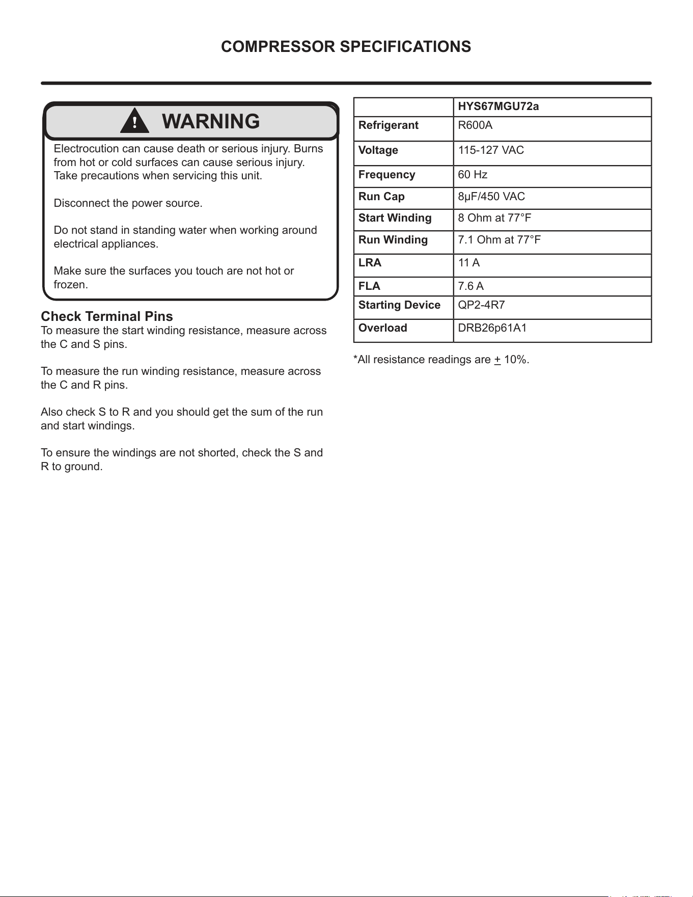
HYS67MGU72a
Refrigerant R600A
Voltage 115-127 VAC
Frequency 60 Hz
Run Cap 8µF/450 VAC
Start Winding 8 Ohm at 77°F
Run Winding 7.1 Ohm at 77°F
LRA 11 A
FLA 7.6 A
Starting Device QP2-4R7
Overload DRB26p61A1
*All resistance readings are + 10%.
Check Terminal Pins
To measure the start winding resistance, measure across
the C and S pins.
To measure the run winding resistance, measure across
the C and R pins.
Also check S to R and you should get the sum of the run
and start windings.
To ensure the windings are not shorted, check the S and
R to ground.
23

If service is required, call your authorized service agency.
Have the following information readily available:
• Model number
• Serial number
• Date purchased
• Name of dealer from whom purchased
Clearly describe the problem that you are having. If you are
unable to obtain the name of an authorized service agency,
or if you continue to have service problems, contact Viking
Range, LLC at (888) 845-4641 or write to:
VIKING RANGE, LLC
PREFERRED SERVICE
111 Front Street
Greenwood, Mississippi 38930 USA
Record the information indicated below. You will need it
if service is ever required. The serial number and model
numbers for your refrigerator are located on the upper wall,
behind the lighting:
Model No. ___________________________________
Serial No. _____________________________________
Date of Purchase ______________________________
Date Installed _________________________________
Dealer’s Name ________________________________
Address _____________________________________
__________________________________________
If service requires installation of parts, use only authorized
parts to insure protection under the warranty.
Keep this manual for future reference.
SERVICE INFORMATION
24

HOUSEHOLD PRODUCT WARRANTY
ICE MACHINE WARRANTY
TWO YEAR FULL WARRANTY
Undercounter ice machines and all of their component parts, except as detailed below*†, are warranted to be free from defective materials or workmanship in
normal residential use for a period of two (2) years from the date of original retail purchase. Viking Range, LLC, warrantor, agrees to repair or replace, at its
option, any part which fails or is found to be defective during the warranty period.
*FULL NINETY (90) DAY COSMETIC WARRANTY:
Product is warranted to be free from cosmetic defects in materials or workmanship (such as scratches on
stainless steel, paint/porcelain blemishes, etc.) for a period of ninety (90) days from the date of original retail purchase or closing date for new
construction, whichever period is longer. Any defects must be reported to the selling dealer within ninety (90) days from date of original retail purchase.
Viking Range, LLC uses high quality processes and materials available to produce all color finishes. However, slight color variation may be noticed because
of the inherent differences in painted parts and porcelain parts as well as differences in kitchen lighting, product locations, and other factors. Therefore,
this warranty does not apply to color variation attributable to such factors.
†FULL NINETY (90) DAY WARRANTY IN “RESIDENTIAL PLUS” APPLICATIONS: Viking products are designed and certified for residential use only. They are
not intended for use in commercial applications. Viking products should only be used in accordance to national and local codes. Viking is not
responsible for property damage or injury resulting from use in a commercial application. To support the manufacturing quality of its appliance’s Viking
will provide a full 90 day warranty for products used in “Residential Plus “applications. This “Residential Plus” warranty applies to applications where use
of the product extends beyond residential use but is in compliance with national and local code. In some jurisdictions these applications are zoned as
residential. Examples of, but not limited to, such applications covered by this warranty are bed and breakfasts, fire stations, private clubs, churches,
condominium/apartment common areas etc. Under this "Residential Plus" warranty, the product, its components and accessories are warranted to be free
from defective material or workmanship for a period of ninety (90) days from the date of original retail purchase. Viking Range, LLC, warranter, agrees to
repair or replace, at its option, any part which fails or is found to be defective during the warranty period. This warranty covers parts and labor. This
warranty excludes use of the product in all commercial locations such as restaurants, food service locations and institutional food service locations.
SIX YEAR FULL WARRANTY ON SEALED REFRIGERATION PARTS AS LISTED
Any sealed refrigeration system component, as listed below, is warranted to be free from defective materials or workmanship in normal household use during the
third through the sixth year from the date of original retail purchase. Viking Range, LLC, warranter, agrees to repair or replace, at its option, any part which fails or is
found to be defective during the warranty period.
Sealed Refrigeration System Components: Compressor, Evaporator, Condenser, Connecting Tubing, Dryer/Strainer
TWELVE YEAR LIMITED WARRANTY ON SEALED REFRIGERATION PARTS AS LISTED
Any sealed refrigeration system component, as listed above, which fails due to defective materials or workmanship in normal household use during the seventh
through the twelfth year from the date of original retail purchase will be repaired or replaced, free of charge for the part itself, with the owner paying all other costs,
including labor.
WARRANTY TERMS
This warranty extends to the original retail purchaser of the product warranted hereunder and to each transferee owner of the product during the term of the
original purchaser's warranty. the warranty is transferable by the original retail purchaser via home sale only. If a transferee owner is unable to provide proof of
purchase from the original purchaser and the product has not been previously registered, the production date of the product, located in the serial number of the
product, will serve as the effective warranty start date.
The activation date of the warranty begins from the date of original retail purchase. In the case of new product purchase via building development sales, activation
begins from the earlier date of either certificate of occupancy or 24 months from date of manufacture. Note date of manufacture is identified by serial tag on
product.
This warranty does not cover units purchased as b-stock, liquidation, salvage, seconds, refurbished, as-is, used products.
This warranty shall apply to products purchased in the United States and Canada. Products must be purchased in the country where service is requested. Warranty
service must be performed by a Viking Range LLC authorized service agency or representative. Warranty shall not apply to damage resulting from abuse, accident,
natural disaster, loss of electrical power to the product for any reason, alteration, improper installation, improper operation, or repair service of the product by
anyone other than a Viking Range LLC authorized service agency or representative. This warranty does not apply to commercial usage. Warrantor is not responsible
for consequential or incidental damage whether arising out of breach of warranty, breach of contract or otherwise. Some jurisdictions do not allow the exclusion or
limitation of incidental or consequential damages, so the above limitations do not apply to you.
Owner shall be responsible for proper installation, providing normal care and maintenance, providing proof of purchase upon request, and making the product
reasonably accessible for service. If the product or one of its component parts contains a defect or malfunction during the warranty period, after a reasonable
number of attempts by the warrantor to remedy the defects or malfunctions, the owner is entitled to either a refund or replacement, at the warrantor’s discretion of
the product or its component part or parts. Warrantor’s liability on any claim of any kind, with respect to the goods or services covered hereunder, shall in no case
exceed the price of the goods or service or part thereof which gives rise to the claim.
WARRANTY SERVICE
Under the terms of this warranty, service must be performed by a Viking Range LLC authorized service agent or representative. Service will be provided during
normal business hours Labor performed at overtime or premium rates shall not be covered by the warranty. To obtain warranty service contact Viking Range LLC
Customer Care at 1-888-845-4641. Please have model number, serial number, and date of original purchase available when calling. IMPORTANT: Retain proof of
original purchase to establish warranty period. The return of the owner registration card is not a condition of warranty coverage. You should, however, return the
owner registration card so Viking Range LLC can contact you should any question of safety arise which could affect you. Any implied warranties of merchantability
and fitness applicable to the above described burner assemblies, infrared rotisserie burners, grill grates, and stainless steel parts are limited in duration to the period
of coverage of the applicable express written limited warranties set forth above. Some jurisdictions do not allow limitations on how long an implied warranty lasts, so
the above limitations may not apply to you. This warranty gives you specific legal rights, and you may also have other rights which may vary from jurisdiction to
jurisdiction.
Specifications subject to change without notice.
25

30735
Viking Range, LLC
111 Front Street
Greenwood, Mississippi 38930 USA
(662) 455-1200
For product information,
call 1-888-(845-4641)
or visit our web site at vikingrange.com
(051225)