OPERATOR'S MANUAL
MODEL #100743
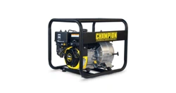
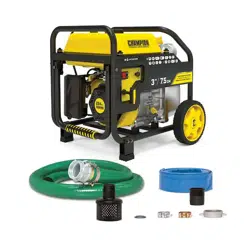
3 iN. (7.5 cM) SEMi-TRASh PUMP
Made in China - REV 20200520 Champion Power Equipment, Inc., Santa Fe Springs, CA USA
or visit championpowerequipment.com
READ AND SAVE ThiS MANUAL. This manual contains important safety precautions which should be read and understood before operating the product. Failure to
do so could result in serious injury. This manual should remain with the product.
Specifications, descriptions and illustrations in this manual are as accurate as known at the time of publication, but are subject to change without notice.
REGISTER YOUR PRODUCT ONLINE
at championpowerequipment.com

2
100743 - 3 iN. (7.5 cM) SEMi-TRASh PUMP
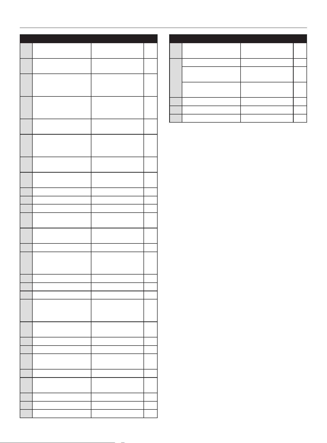
TAbLE Of cONTENTS
TAbLE Of cONTENTS
introduction ................................................... 3
Safety Definitions
.......................................... 3
important Safety instructions
....................... 4
Fuel Safety .........................................................6
Safety and Dataplate Labels .......................................7
Safety Symbols .....................................................8
Operation Symbols ............................................... 10
Quickstart Label Symbols........................................ 10
controls and features ................................. 11
Parts Included .................................................... 12
Assembly ..................................................... 13
Remove the Water Pump from the Shipping Carton ............ 13
Install Handle, Wheels, and Support Legs ...................... 13
Add Engine Oil .................................................... 13
Add Fuel .......................................................... 14
Operation ..................................................... 15
Water Pump Location ............................................ 15
Connecting a Hose Kit ........................................... 16
Priming the Pump ................................................ 20
Before Starting the Engine ....................................... 21
Starting the Engine ............................................... 21
Stopping the Engine .............................................. 22
Operation at High Altitude ....................................... 22
Maintenance ................................................ 23
Cleaning the Water Pump ........................................ 23
Changing the Engine Oil ......................................... 23
Cleaning and Adjusting the Spark Plug(s) ....................... 24
Cleaning the Air Filter ............................................ 24
Cleaning the Spark Arrestor ..................................... 24
Adjusting the Governor ........................................... 25
Maintenance Schedule ........................................... 25
Storage ........................................................ 25
Water Pump Storage ............................................. 25
Short Term Engine Storage (Up to 30 Days) .................... 25
Mid Term Engine Storage ( 30 Days – 1 year) .................. 25
Long Term Storage ............................................... 26
Specifications .............................................. 27
Water Pump Specifications ...................................... 27
Engine Specifications ............................................ 27
Engine Oil Specifications ......................................... 27
Fuel Specifications ............................................... 27
Spark Plug Specifications ........................................ 27
Valve Specifications .............................................. 27
Important Message About Temperature......................... 27
Parts Diagram - Frame and Engine ............................. 28
Parts List ......................................................... 29
Engine Parts Diagram ............................................ 31
Engine Parts List ................................................. 32
Troubleshooting ........................................... 34

3
100743 - 3 iN. (7.5 cM) SEMi-TRASh PUMP
iNTRODUcTiON
iNTRODUcTiON
Congratulations on your purchase of a Champion Power Equipment
(CPE) product. CPE designs, builds, and supports all of our
products to strict specifications and guidelines. With proper
product knowledge, safe use, and regular maintenance, this
product should bring years of satisfying service.
Every effort has been made to ensure the accuracy and
completeness of the information in this manual at the time of
publication, and we reserve the right to change, alter and/or
improve the product and this document at any time without prior
notice.
Since CPE highly values how our products are designed,
manufactured, operated and are serviced, and also highly value
your safety and the safety of others, we would like you to take the
time to review this product manual and other product materials
thoroughly and be fully aware and knowledgeable of the assembly,
operation, dangers and maintenance of the product before use.
Fully familiarize yourself, and make sure others who plan on
operating the product fully familiarize themselves too, with the
proper safety and operation procedures before each use. Please
always exercise common sense and always err on the side
of caution when operating the product to ensure no accident,
property damage, or injury occurs. We want you to continue to use
and be satisfied with your CPE product for years to come.
When contacting CPE about parts and/or service, you will need to
supply the complete model and serial numbers of your product.
Transcribe the information found on your product’s nameplate
label to the table below
CPE TEChNICaL SUPPORT TEam
1-877-338-0999
mODEL NUmBER
100743
SERIaL NUmBER
DaTE OF PURChaSE
PURChaSE LOCaTION
SAfETY DEfiNiTiONS
The purpose of safety symbols is to attract your attention to
possible dangers. The safety symbols, and their explanations,
deserve your careful attention and understanding. The safety
warnings do not by themselves eliminate any danger.
The instructions or warnings they give are not substitutes for
proper accident prevention measures.
DANGER
DANGER indicates a hazardous situation which, if not avoided,
will result in death or serious injury.
WARNiNG
WARNING indicates a hazardous situation which, if not
avoided, could result in death or serious injury.
cAUTiON
CAUTION indicates a hazardous situation which, if not avoided,
could result in minor or moderate injury.
NOTicE
NOTICE indicates information considered important, but not
hazard-related (e.g., messages relating to property damaged).
4
100743 - 3 iN. (7.5 cM) SEMi-TRASh PUMP
iMPORTANT SAfETY iNSTRUcTiONS
iMPORTANT SAfETY iNSTRUcTiONS
WARNiNG
Cancer and Reproductive Harm – www.P65Warnings.ca.gov
DANGER
Water pump engine exhaust contains carbon monoxide,
a colorless, odorless, poison gas. Breathing carbon monoxide
will cause nausea, dizziness, fainting or death.
If you start to feel dizzy or weak, get to fresh air immediately.
OPERaTE ThE WaTER PUmP OUTDOORS ONLY IN a WELL
VENTILaTED aREa aND POINT EXhaUST aWaY.
DO NOT operate the water pump inside any building, including
garages, basements, crawlspaces and sheds, enclosure
or compartment, including the storage compartment of a
recreational vehicle.
DO NOT allow exhaust fumes to enter a confined area through
windows, doors, vents or other openings.
DANGER
Using an engine indoors CaN KILL YOU IN mINUTES. Engine
exhaust contains carbon monoxide. This is a poison you cannot
see or smell.
NEVER use inside a home or garage, EVEN IF doors and
windows are open.
ONLY use OUTSIDE and far away from windows, doors,
and vents.
Install battery-operated carbon monoxide alarms or plug-in
carbon monoxide alarms with battery back-up according to the
manufacturer’s instructions.
DANGER
Rotating parts can entangle hands, feet, hair, clothing and/or
accessories. Traumatic amputation or severe laceration can
result.
Keep hands and feet away from rotating parts.
Tie up long hair and remove jewelry.
Operate equipment with guards in place.
DO NOT wear loose-fitting clothing, dangling drawstrings or
items that could become caught.
WARNiNG
Spark from removed spark plug wire can result in fire or
electrical shock.
When servicing the water pump:
Disconnect the spark plug wire and place it where it cannot
contact the plug or any other metal object.
DO NOT check for spark with the plug removed.
Use only approved spark plug testers.
WARNiNG
Contact with electrical power source can cause electric shock
or burn.
NEVER spray in the direction of or near a power source/
electrical outlet.
WARNiNG
Running engines produce heat. Severe burns can occur on
contact. Combustible material can catch fire on contact.
DO NOT touch hot surfaces.
Avoid contact with hot exhaust gases.
Allow equipment to cool before touching.
Maintain at least 3 ft. (91.4 cm) of clearance on all sides to
ensure adequate cooling.
Maintain at least 5 ft. (1.5 m) of clearance from combustible
materials.
DANGER
DO NOT pump gasoline, fuel, fuel-oil mixtures, detergents,
acids, chemicals, beverages, pesticides, fertilizers or any other
flammable liquid or corrosive.

5
100743 - 3 iN. (7.5 cM) SEMi-TRASh PUMP
iMPORTANT SAfETY iNSTRUcTiONS
WARNiNG
DO NOT immerse the water pump in water.
DANGER
The water pump develops powerful force.
DO NOT move the water pump when it is in use.
DO NOT use hoses or connectors that are worn, damaged or
frayed.
DO NOT allow children or unqualified persons to operate or
service the water pump.
DO NOT open top plug or drain plug.
WARNiNG
Rapid retraction of the starter cord will pull hand and arm
towards the engine faster than you can let go. Unintentional
startup can result in entanglement, traumatic amputation or
laceration. Broken bones, fractures, bruises or sprains could
result.
When starting engine, pull the starter cord slowly until
resistance is felt and then pull rapidly to avoid kickback.
WARNiNG
DO NOT pump salt, sludge, sewer, sea, or any other type of
water containing solid material.
cAUTiON
Exceeding the pump specification for total head can damage
the pump and/or hose kits connected to it.
DO NOT modify the pump in any way. DO NOT attempt to
exceed the rated flow. Attempting to increase the rated flow
may damage the unit and/or shorten its life.
NOTicE
DO NOT run the pump dry.
Running the pump dry can destroy the pump seals and will
void the warranty. If the pump was running while dry, stop
the engine and allow it to cool thoroughly before filling the
chamber with water.
cAUTiON
Improper treatment or use of the water pump can damage it,
shorten its life and void your warranty.
Use the water pump only for intended uses.
Operate only on level surfaces.
DO NOT expose water pump to excessive moisture, dust,
or dirt.
DO NOT allow any material to block the cooling slots.
DO NOT use the engine if:
– Equipment sparks, smokes or emits flames
– Equipment vibrates excessively
WARNiNG
Use of this water pump can create wet, slippery walking
surfaces.
– Use only on a level surface.
– Make sure there is proper drainage to dissipate water.

6
100743 - 3 iN. (7.5 cM) SEMi-TRASh PUMP
iMPORTANT SAfETY iNSTRUcTiONS
fuel Safety
DANGER
GaSOLINE aND GaSOLINE VaPORS aRE hIGhLY
FLammaBLE aND EXPLOSIVE.
Fire or explosion can cause severe burns or death.
Gasoline and gasoline vapors:
– Gasoline is highly flammable and explosive.
– Gasoline can cause a fire or explosion if ignited.
– Gasoline is a liquid fuel but its vapors can ignite.
– Gasoline is a skin irritant and needs to be cleaned up
immediately if spilled on skin or clothes.
– Gasoline has a distinctive odor, this will help detect potential
leaks quickly.
– In any petroleum gas fire, flames should not be extinguished
unless by doing so the fuel supply valve can be turned OFF.
This is because if a fire is extinguished and a supply of fuel is
not turned OFF, then an explosion hazard could be created.
– Gasoline expands or contracts with ambient temperatures.
Never fill the gasoline tank to full capacity, as gasoline needs
room to expand if temperatures rise.
When adding or removing gasoline:
DO NOT light or smoke cigarettes.
Turn the engine off and let it cool for at least two minutes before
removing the gasoline cap. Loosen the cap slowly to relieve
pressure in the tank.
Only fill or drain gasoline outdoors in a well-ventilated area.
DO NOT pump gasoline directly into the engine at the gas station.
Use an approved container to transfer the fuel to the engine.
DO NOT overfill the gasoline tank.
Always keep gasoline away from sparks, open flames, pilot lights,
heat and other sources of ignition.
When starting the engine:
DO NOT attempt to start a damaged engine.
Make certain that the gasoline cap, air filter, spark plug, fuel lines
and exhaust system are properly in place.
Allow spilled gasoline to evaporate fully before attempting to start
the engine.
Make certain that the water pump is resting firmly on level ground.
When operating the water pump:
DO NOT move or tip the water pump during operation.
DO NOT tip the water pump or allow fuel or oil to spill.
When transporting or servicing the water pump:
Make certain that the fuel valve is in the OFF position, the gasoline
tank is empty.
Disconnect the spark plug wire.
When storing the water pump:
Store away from sparks, open flames, pilot lights, heat and other
sources of ignition.
Do not store water pump or gasoline near furnaces, water heaters,
or any other appliances that produce heat or have automatic
ignitions.
WARNiNG
NEVER use a gasoline container, gasoline tank, or any other
fuel item that is broken, cut, torn or damaged.
7
100743 - 3 iN. (7.5 cM) SEMi-TRASh PUMP
iMPORTANT SAfETY iNSTRUcTiONS
Side Side
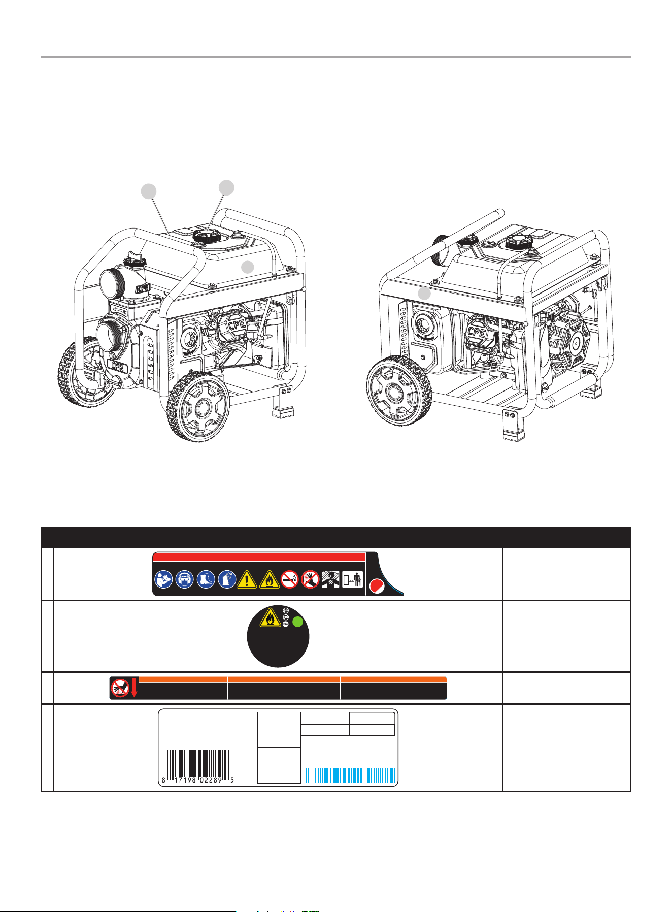
Safety and Dataplate Labels
These labels warn you of potential hazards that can cause serious injury. Read them carefully.
If a label comes off or becomes hard to read, contact Technical Support Team for possible replacement.
LaBEL DESCRIPTION
a
2012-L-OP-a
DaNGER PELIGRO DaNGER
2012-L-OP-a
K 109 485 --- ---
ColorsLPN 2012-L-O P
Rev A
Size Spec’d by CPEC
Artwork Notes
2mm safe margin;
to be pr inted on w hite substrate
Revision Changes
---
This ar twork belongs to Champion Power Equipment. The contents are confidential and privileged and shall not be disclosed to or used by or for
outside parties without the explicit consent of Champion Power Equipment.
Safety Symbols/
CO Danger
B
UNLEADED FUEL ONLY. Minimum octane
rating of 87. Maximum 10% ethanol.
GASOLINA REGULAR SOLAMENTE.
87 octanos como mínimo. Máximo de
etanol de 10%.
ESSENCE SANS PLOMB
SEULEMENT. Indice d’octane
minimal de 87. Maximum
10 % d'éthanol.
2
2011-L-OP-a
K 376 --- --- ---
ColorsLPN 2 011-L-OP
Rev A
Size 38 x 38 mm
Artwork Notes
2mm safe margin;
to be pr inted on white su bstra te
Revision Changes
---
This ar twork belongs to Champion Power Equipment. The contents are con fidential and privileged and shall not be disclosed to or used by or for
outside parties without the explicit consent of Champion Power Equipment.
Fuel
C
WaRNING
DO NOT TOUCH!
Exhaust gases, muffler
and engine components
are extremely HOT and
cause burns.
Operation of this equipment may create sparks that can start
fires around dry vegetation. A spark arrestor may be
required. The operator should contact local fire agencies for
laws and regulations relating to fire p revention requirements.
If installed, clean every 100 hour s or every season.
aDVERTENCIa
¡NO TOCAR! Los gases de
escape, el silenciador y los
compnonentes del motor están
extremadamente CALIEN TES y
causan quemaduras.
La operación de este equipo puede p roducir chispas que pueden provocar
incendios alrededor de la vegetación seca. Un supresor de chispas puede que
sea necesario. El operador debe comunicarse con las agencias locales de
bomberos para las leyes y reglamentos relativos a los requisitos de prevención
de incendios . Si está instalado, limp ie cada 100 horas o cada tem porada.
aVERTISSEmENT
NE PAS TOUCHER! Les ga z
d’échappement, le silencieux
et les pièces du moteur sont
extrêmeme nt CHAUDS et
peuvent causer des brûlures.
Cet équipem ent peut créer des étince lles et provoquer un incend ie dans la
végétation sèche. Un pare-ét incelles peut être requis. L’utilisateur doit
communiquer avec le service d’incendie local pour connaître les lois et
les règlements en matière de prévention des incendies. Si elle est
installée, nettoyez la génératrice toutes les 100 heures ou chaque saison.
1035-L-SF-C
ColorsLPN 1035-L-SF
Rev C
Size 369 x 2 6 mm
Artwork Notes
3mm corner radius; 2mm safe margin
Revision Changes
C: updated some FR translation words.
This artw ork belongs to Champio n Power Equipment. Th e contents are confi dential and privileg ed and shall not be disclo sed to or used by or for
outside par ties without th e explicit consent o f Champion Power Equip ment.
K
485 152 --- ---
Hot Surface
D
CHAMPION POWER EQUIPMENT, INC.
12039 SMITH AVENUE
SANTA FE SPRINGS, CA 90670
USA / É.-U.
1-877-338-0999
WWW.CHAMPIONPOWEREQUIPMENT.COM
MADE IN CHINA / FABRIQUÉ EN CHINE
MODEL
MODÈLE
MANUFACTURE DATE
DATE DE FABRICATION
FLOW (GPM / LPM)
DÉBIT (GPM / LPM)
INLET DIAMETER
DIAMÈTRE D'ENTRÉE
2216-L-PR-a
100743
264 / 1000
3 IN.
7.5 CM
SERIAL NO. / N° DE SÉRIE
XXXX
XXXXXXXXXXXX
K --- --- --- ---
ColorsLPN 2216-L-PR
Rev A
Size 123 x 40 mm
Artwork Notes
3mm corner radius; 2mm safe margin
Revision Changes
---
This ar twork belongs to Champion Power Equipment. The contents are confidential and privileged and shall not be disclosed to or used by or for
outside parties without the explicit consent of Champion Power Equipment.
Dataplate
c
D
b
A
8
100743 - 3 iN. (7.5 cM) SEMi-TRASh PUMP
iMPORTANT SAfETY iNSTRUcTiONS
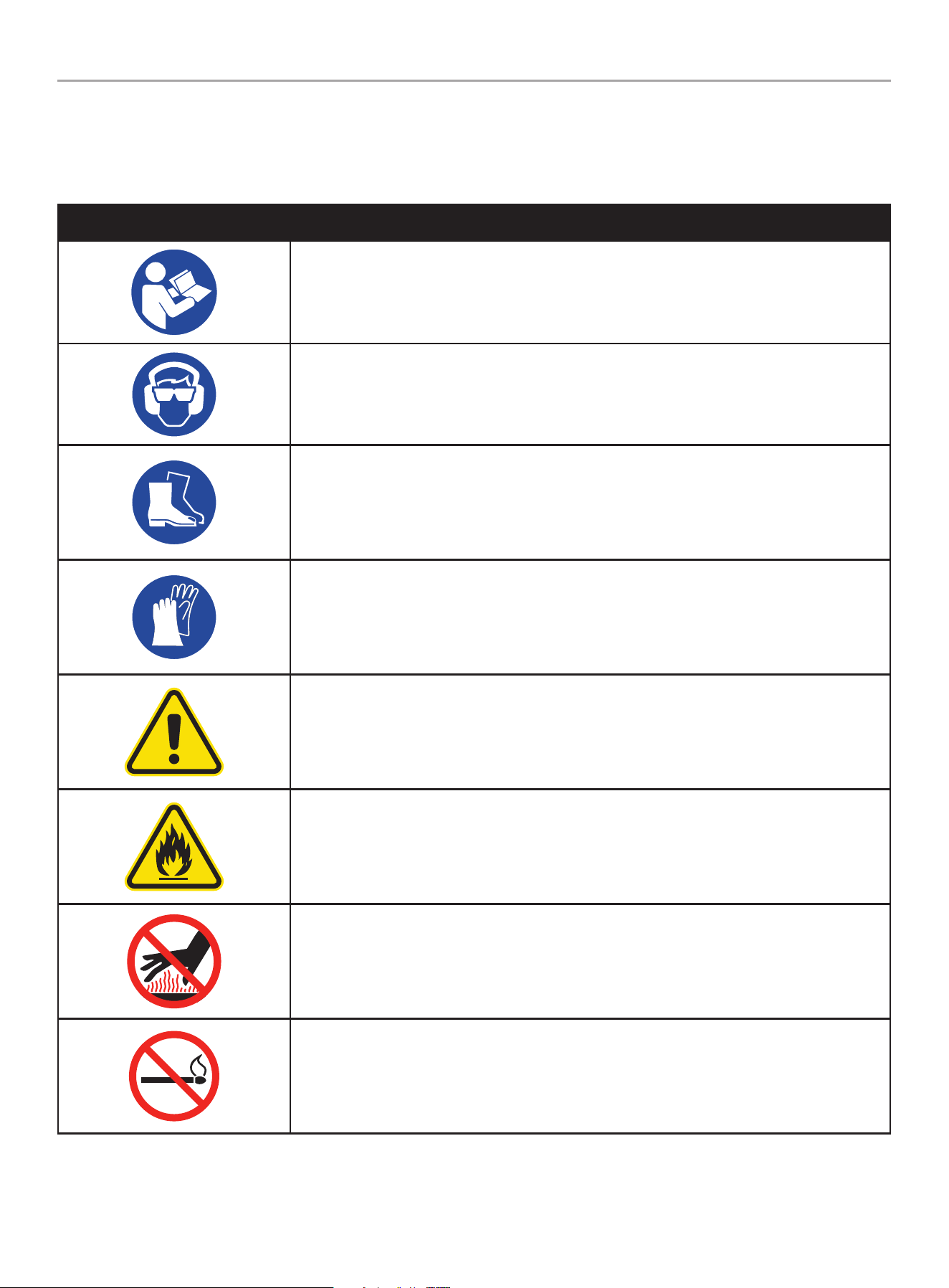
Safety Symbols
Some of the following symbols may be used on this product. Please study them and learn their meaning. Proper interpretation of these
symbols will allow you to more safely operate the product.
SYmBOL mEaNING
Read Operator’s manual. To reduce the risk of injury, user must read and understand operator’s
manual before using this product.
Eye and Ear Protection. Always wear safety goggles or safety glasses with side shields, and as
necessary a full face-shield as well as full ear protection when operating this product.
Footwear. Always wear safety shoes or heavy boots when operating the machine.
Gloves. Always wear nonslip, heavy-duty protective gloves when operating this product.
Safety alert. Precautions that involve your safety.
Risk of Fire. Fuel and its vapors are extremely flammable and explosive. Fire can cause severe
burns or death. Do not add fuel while the product is operating or still hot.
hot Surface. To reduce the risk of injury or damage, avoid contact with any hot surface
Open Flame alert. Fuel and its vapors are extremely flammable and explosive. Keep fuel away
from smoking, open flames, sparks, pilot lights, heat, and other ignition sources.
9
100743 - 3 iN. (7.5 cM) SEMi-TRASh PUMP
iMPORTANT SAfETY iNSTRUcTiONS
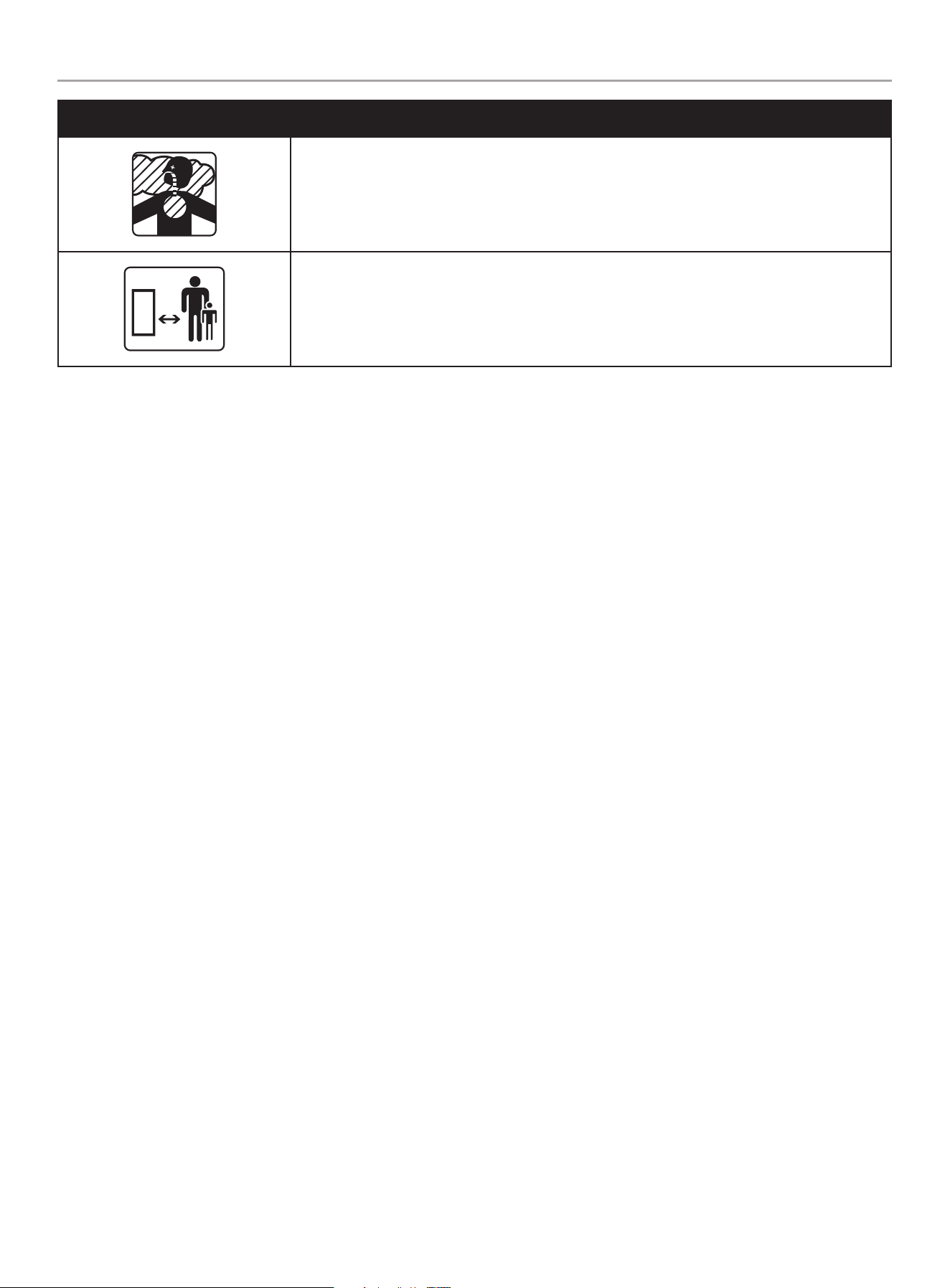
SYmBOL mEaNING
Toxic Fumes. The engine exhaust from this product contains chemicals known to the state of
California to cause cancer and birth defects and other reproductive harm.
Risk of asphyxiation. This engine emits carbon monoxide, an odorless, colorless poison gas.
Breathing carbon monoxide can cause nausea, fainting or death. Use only in a well ventilated
area.
Clearance. Keep all objects including others at least 10 feet (3m) from this machine.
Only one person should operate the water pump and load the logs
10
100743 - 3 iN. (7.5 cM) SEMi-TRASh PUMP
iMPORTANT SAfETY iNSTRUcTiONS
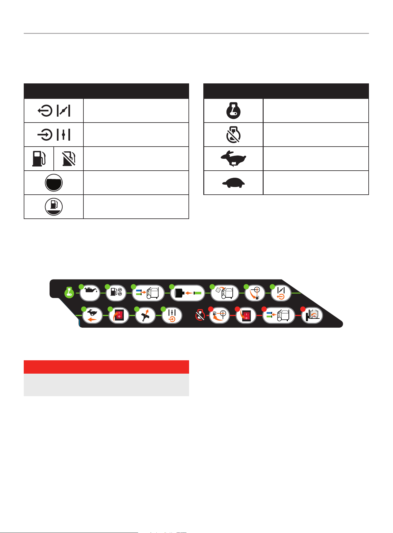
Operation Symbols
Some of the following symbols may be used on this product. Please study them and learn their meaning. Proper interpretation of these
symbols will allow you to more safely operate the product.
Quickstart Label Symbols
Some of the following symbols may be used on this product. Please study them and learn their meaning. Proper interpretation of these
symbols will allow you to more safely operate the product.
Starting the Engine
DANGER
move water pump outside and far away from windows,
doors and intake ventilation covers.
1. Check oil level. Recommended oil is 10W-30.
2. Check fuel level.
3. Connect inlet and outlet hoses
4. Connect inlet filter
5. Prime the water pump
6. Move the fuel valve to the “ON” position.
7. Move the choke lever to the “ChOKE” position by pulling out.
8. Move throttle to “FaST” position.
9. Press engine switch to “ON” position.
SYmBOL mEaNING
Choke. Pull choke knob to “CHOKE”
position.
Run. Push choke knob to “RUN”
position.
Fuel/Gasoline Valve On/Off
Fuel Gauge: Full
Fuel Gauge: Empty
SYmBOL mEaNING
On
Stop or Off
Throttle Lever - Fast
Throttle Lever - Slow
10. Pull the starter cord slowly until resistance is felt and then
pull rapidly.
11. As engine warms up, move the choke to “RUN” by pushing in
and adjust the throttle as needed
Stopping
1. Move the fuel valve to the “OFF” position.
2. Press the engine switch to the “OFF” position.
3. Disconnect inlet and outlet hoses for storage.
4. Remove drain plug (bottom) before storage.
2174-L-OP-a
8
1
10W-30
2
6 73 54
1 42 3119 10
K 376 485 152 300 186CG1CG7
ColorsLPN 2174-L-OP
Rev A
Size Spec’d by CPEC
Artwork Notes
3mm corner radius; 2mm safe margin; to be printed
on white substrate.
Revision Changes
---
This ar twork belongs to Champion Power Equipment. The contents are confidential and privileged and shall not be disclosed to or used by or for
outside parties without the explicit consent of Champion Power Equipment.
11
100743 - 3 iN. (7.5 cM) SEMi-TRASh PUMP
cONTROLS AND fEATURES
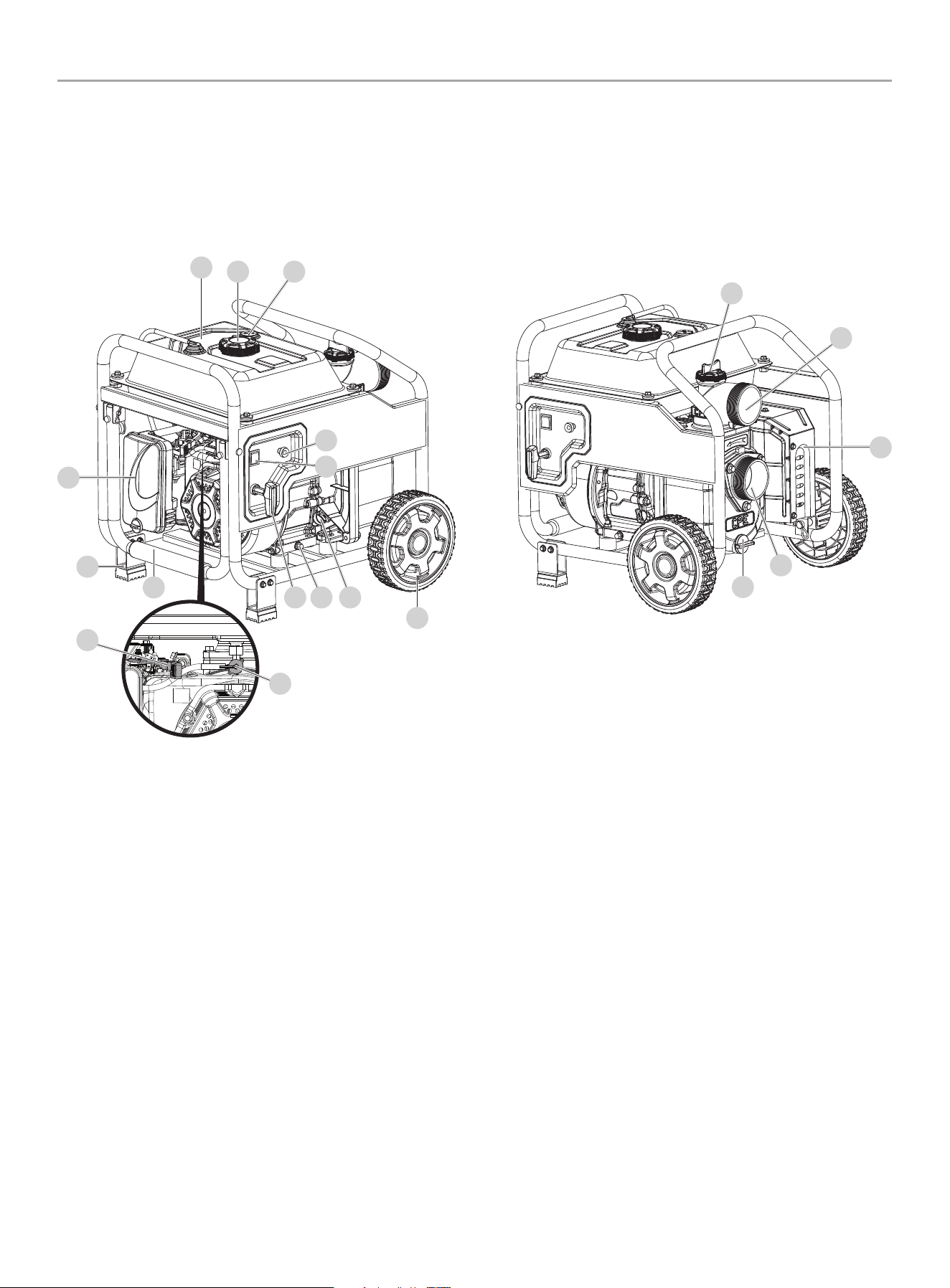
cONTROLS AND fEATURES
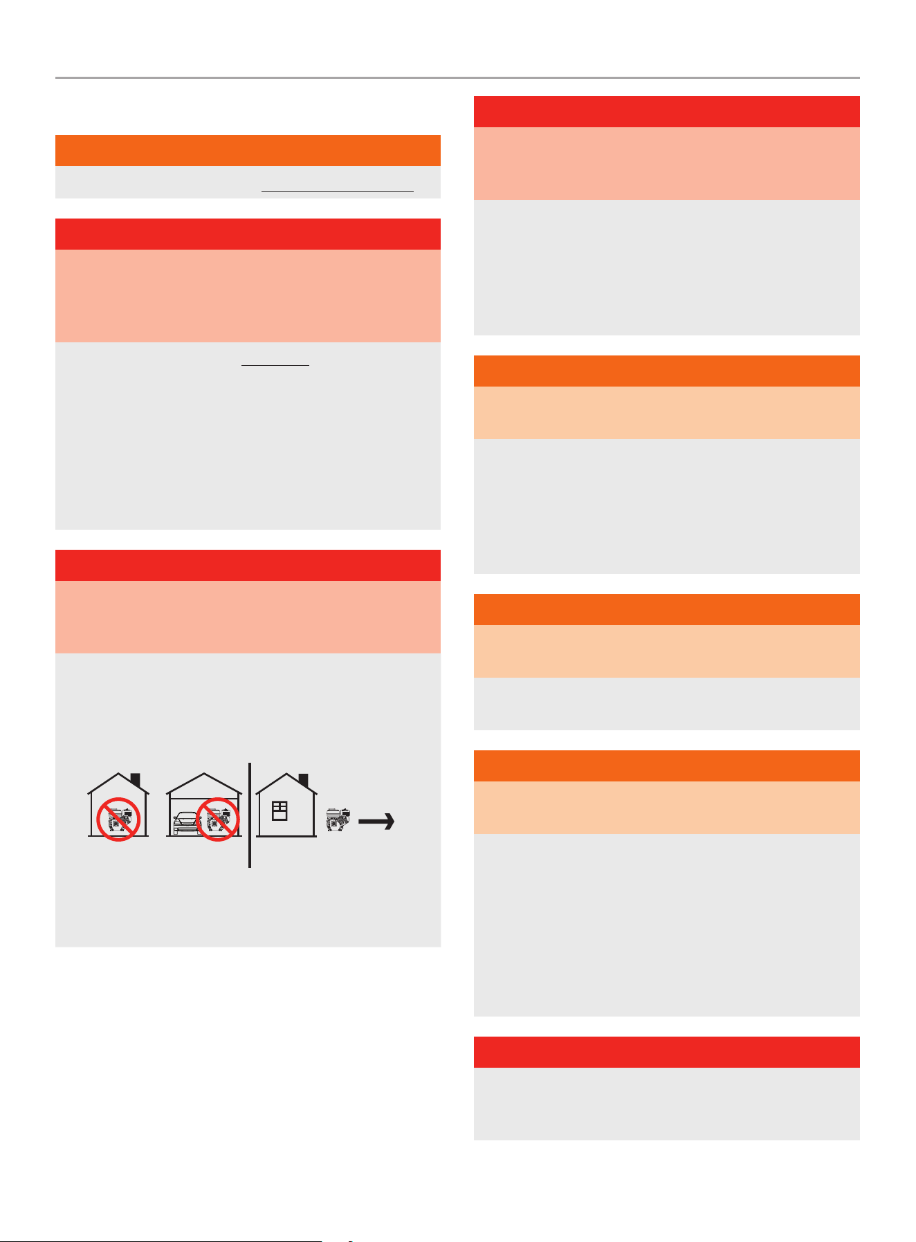
Read this operator’s manual before operating your water pump. Familiarize yourself with the location and function of the controls and
features. Save this manual for future reference.
1. Gasoline Tank Cap
2. Gasoline Tank
3. Air Filter
4. Support Leg
5. Transport Handle
6. Throttle
7. Fuel Valve
8. Recoil Handle
9. Oil Drain Bolt (on each side)
10. Engine Oil Fill Cap/Dipstick
11. Wheels
12. Engine Switch
13. Choke
14. Fuel Gauge
15. Drain Plug (bottom)
16. Inlet
17. Muffler
18. Outlet
19. Priming Cap (top)
141
2
15
18
19
16
5
11
8 9 10
3
4
12
13
17
6
7
12
100743 - 3 iN. (7.5 cM) SEMi-TRASh PUMP
cONTROLS AND fEATURES
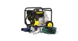
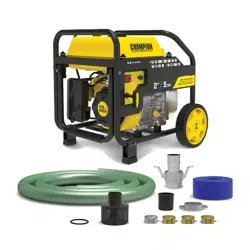
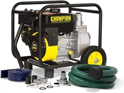
Parts included
assembly Parts
Part Part Qty. hardware Needed hardware Qty. Tool Needed
Wheels 2
Wheel cap 2
N/AR-clip 2
Roll pin Ø16×96 2
Support Leg 2
Bolt M6×40 4 1× 8mm wrench or socket
Flange lock nut M6 4 1× 10mm wrench or socket
Discharge hose (blue) 1
Outlet hose adapter 1
N/AOutlet hose fitting 1
Gasket 1
Silver colored hose clamp
3” 74-79 mm
1 1× 13mm wrench or socket
Suction hose (green)
1
Cam lock coupler (2 parts,
coupler and fitting)
1
N/A
1
Filter (2 parts) 1
Gold colored hose clamp
3” 80-85 mm
3 1× 13mm wrench or socket
Accessory Bag 1 N/A
Engine oil funnel 1 N/A
Teflon
®
tape 1 N/A
Parts Not Included
– Engine Oil (10W-30)
13
100743 - 3 iN. (7.5 cM) SEMi-TRASh PUMP
ASSEMbLY
ASSEMbLY
Your water pump requires some assembly. This unit ships from
the factory without oil. It must be properly serviced with fuel and
oil before operation. For questions regarding the assembly of your
water pump, call our help line at 1-877-338-0999. Please have
your serial number and model number available.
Remove the Water Pump from the Shipping
carton
1. Set the shipping carton on a solid, flat surface.
2. Remove all contents from the carton except the water pump.
3. Carefully cut each corner of the box from top to bottom.
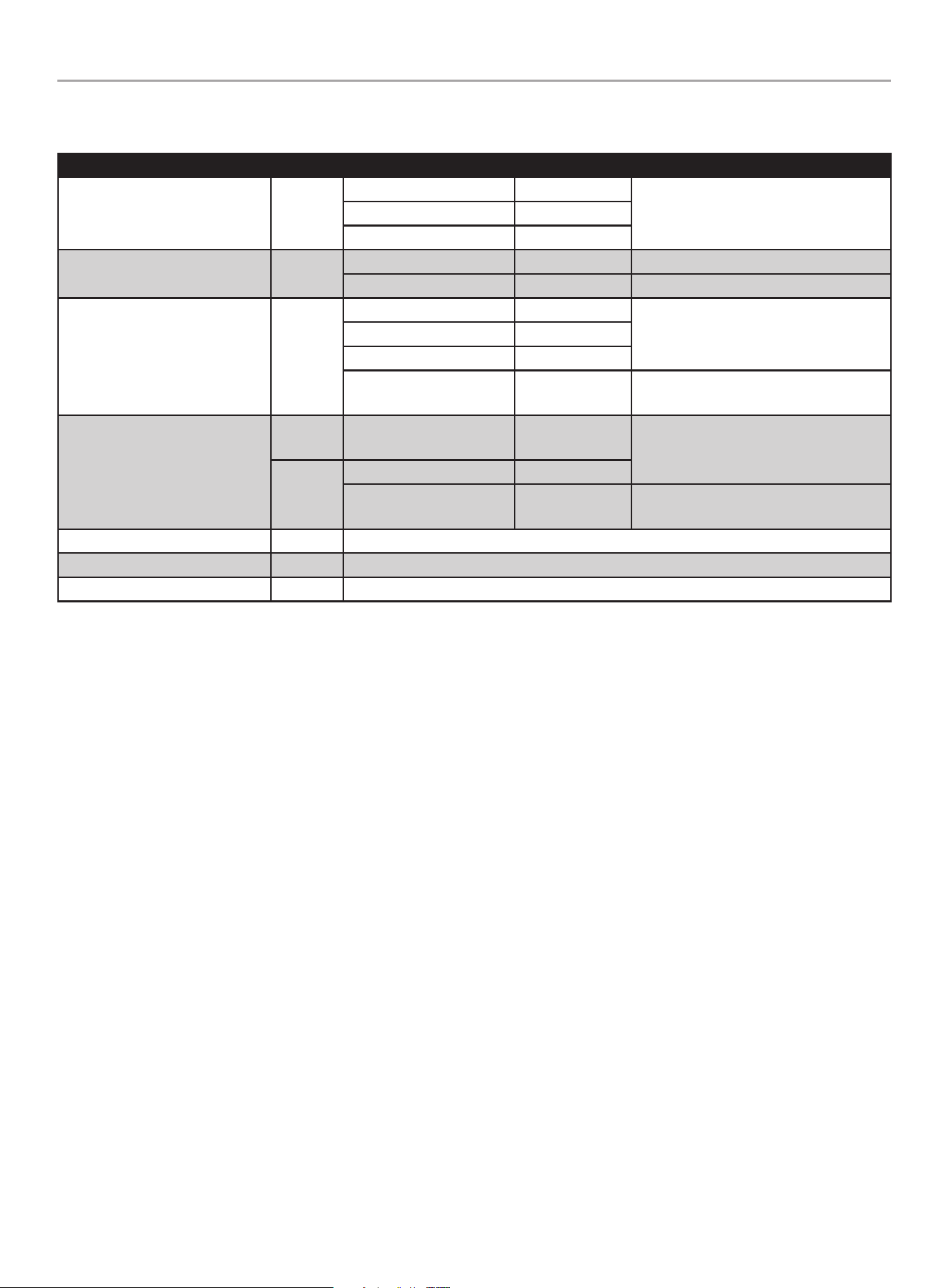
install handle, Wheels, and Support Legs
Wheels
1. Before adding fuel and oil, carefully pivot the water pump up
and forward so that it rests engine side down. Place a piece
of cardboard from the packaging or moving blanket on the
ground before tipping forward.
2. Slide the roll pin through the wheel from the outside.
3. Slide the roll pin through the mount point on the frame.
4. Secure with the R-clip.
5. Repeat to attach the second wheel.
6. Add wheel caps to protect the roll pins.
Support Legs
1. Attach the supports legs to the water pump frame with
(2) M6 × 40 flange bolts and (2) M6 flange lock nuts per leg.
Tighten to 7.4±1.5 lbf-ft (10±2 Nm).
2. Repeat to attach the second leg.
3. Slowly tip the water pump back down so that it rests on the
support legs.
Add Engine Oil
cAUTiON
DO NOT attempt to crank or start the engine before it has been
properly filled with the recommended type and amount of oil.
Damage to the engine as a result of failure to follow these
instructions will void your warranty.
NOTicE
The engine rotor has a sealed, pre-lubricated ball bearing that
requires no additional lubrication for the life of the bearing.
NOTicE
The recommended oil type is 10W-30 automotive oil.
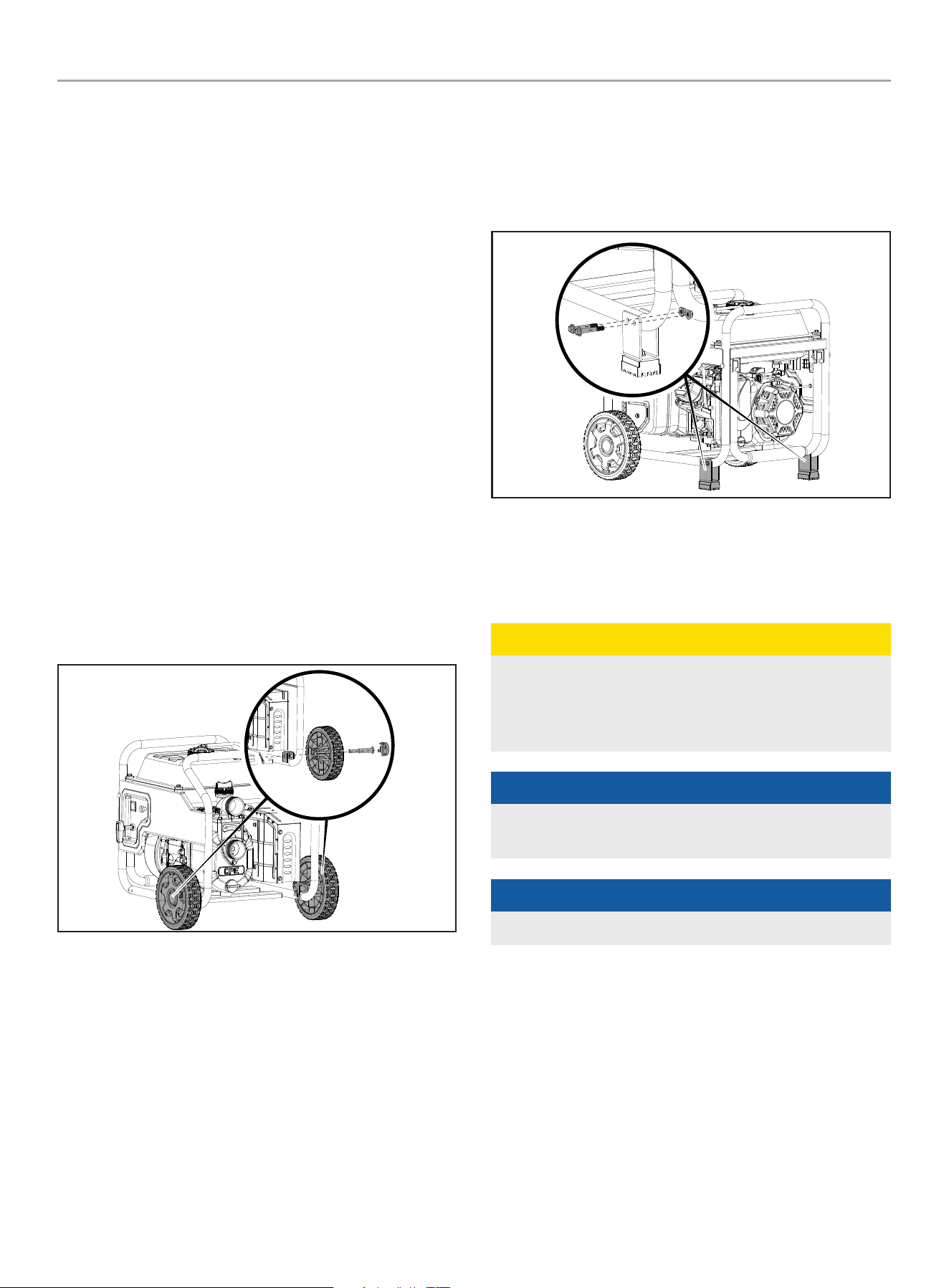
1. Place the water pump on a flat, level surface.
2. Remove oil fill cap/dipstick to add oil.
3. Using a funnel, add up to 16.9 fl. oz (500 ml) of oil and
replace oil fill cap/dipstick. DO NOT OVERFILL.
14
100743 - 3 iN. (7.5 cM) SEMi-TRASh PUMP
ASSEMbLY
4. Check engine oil level before every use and add as needed.
MAX
OIL DIP STICK
NOTicE
Once oil has been added, a visual check should show oil about
1-2 threads from running out of the fill hole.
If using the dipstick to check oil level, DO NOT screw in the
dipstick while checking.
NOTicE
Check oil often during the break-in period. Refer to the
Maintenance section for recommended service intervals.
cAUTiON
The engine is equipped with a low oil shut-off and will stop
when the oil level in the crankcase falls below the threshold
level.
NOTicE
The first 5 hours of run time is the break-in period for the
engine. During the break in period, it is recommended to use
standard automotive, non-synthetic blended oils. After the
break-in period, synthetic oil can be used but is not required.
Adjusting throttle setting will increase/ decrease engine speed
helping to seat piston rings. Avoid bogging or lugging the
engine down and avoid prolonged running at constant RPM.
After the 5-hour break-in period, change the oil.
NOTicE
Synthetic oil may be used after the 5 hour initial break-in
period. Using synthetic oil does not decrease the recommended
oil change interval. Full synthetic 5W-30 oil will aid in starting
in cold ambient < 41º F (5º C).
-20 0 20 40 60
Ambient temperature
Recommended Engine Oil Type
80 100 120
-28.9
°F
°C -17.8 -6.7 4.4 15.6 26.7 37.8 48.9
10W-30
5W-30 Synthetic
10W-405W-30
NOTicE
Weather will affect engine oil and engine performance. Change
the type of engine oil used based on weather conditions to suit
the engine needs.
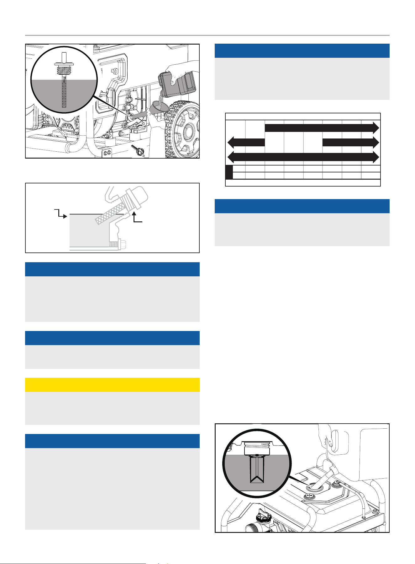
Add fuel
Use clean, fresh, regular unleaded gasoline with a minimum
octane rating of 87 and an ethanol content of less than 10% by
volume. ybc
DO NOT mix oil with gasoline.
1. Place the water pump on a flat, level surface.
2. Remove the gasoline cap.
3. Slowly add gasoline to the tank. DO NOT OVERFILL. Gasoline
can expand after filling. A minimum of ¼ in. (6.4 mm) of
space left in the tank is required for gasoline expansion,
although more than ¼ in. (6.4 mm) is recommended. Gasoline
can be forced out of the tank as a result of expansion if
overfilled, and can affect the stable running condition of the
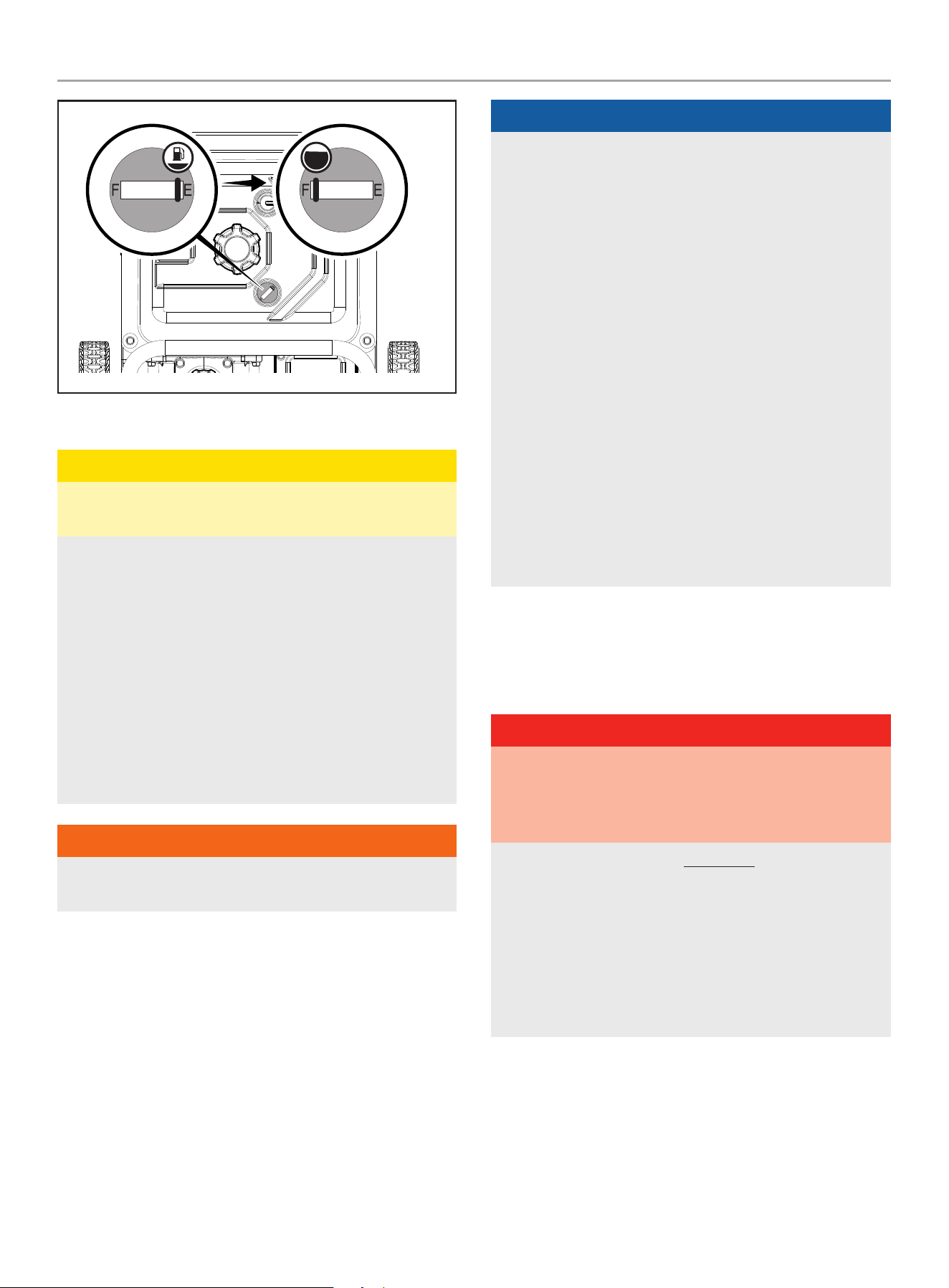
water pump. The approximate fuel level is shown on the fuel
gauge on top of the fuel tank.
15
100743 - 3 iN. (7.5 cM) SEMi-TRASh PUMP
OPERATiON
EmPTY FULL
4. Screw on the gasoline cap and wipe away any spilled fuel.
cAUTiON
Use regular unleaded gasoline with a minimum octane rating
of 87 and an ethanol content of less than 10% by volume.
DO NOT light cigarettes or smoke when filling the tank.
DO NOT mix oil and gasoline.
Fill tank to approximately ¼ in. (6.4 mm) below the top of the
tank to allow for gasoline expansion.
DO NOT pump gasoline directly into the water pump at the
pump. Use an approved container to transfer the gasoline to
the water pump.
DO NOT fill tank indoors.
DO NOT fill tank when the engine is running or hot.
DO NOT overfill the tank.
WARNiNG
Pouring gasoline too fast through the fuel screen may result in
blow back of gasoline at the operator while filling.
NOTicE
Our engines work well with 10% or less ethanol blend
gasoline. When using ethanol-gasoline blends there are some
issues worth noting:
– Ethanol-gasoline blends can absorb more water than
gasoline alone.
– These blends can eventually separate, leaving water or a
watery goo in the tank, fuel valve and carburetor.
– With gravity-fed supplies, the compromised gasoline can
be drawn into the carburetor and cause damage to the
engine and/or potential hazards.
– There are only a few suppliers of fuel stabilizer that are
formulated to work with ethanol-gasoline blends.
– Any damages or hazards caused by using improper
gasoline, improperly stored gasoline, and/or improperly
formulated stabilizers, are not covered by manufacturer’s
warranty.
It is advisable to always shut off the gasoline supply, run the
engine to starvation and drain the tank when the equipment is
not in use for more than 30 days.
OPERATiON
Water Pump Location
DANGER
Water pump engine exhaust contains carbon monoxide,
a colorless, odorless, poison gas. Breathing carbon monoxide
will cause nausea, dizziness, fainting or death.
If you start to feel dizzy or weak, get to fresh air immediately.
OPERaTE ThE WaTER PUmP OUTDOORS ONLY IN a WELL
VENTILaTED aREa aND POINT EXhaUST aWaY.
DO NOT operate the water pump inside any building, including
garages, basements, crawlspaces and sheds, enclosure
or compartment, including the storage compartment of a
recreational vehicle.
DO NOT allow exhaust fumes to enter a confined area through
windows, doors, vents or other openings.
16
100743 - 3 iN. (7.5 cM) SEMi-TRASh PUMP
OPERATiON
DANGER
Using an engine indoors CaN KILL YOU IN mINUTES. Engine
exhaust contains carbon monoxide. This is a poison you cannot
see or smell.
NEVER use inside a home or garage, EVEN IF doors and
windows are open.
ONLY use OUTSIDE and far away from windows, doors,
and vents.
Install battery-operated carbon monoxide alarms or plug-in
carbon monoxide alarms with battery back-up according to the
manufacturer’s instructions.
WARNiNG
Running engines produce heat. Severe burns can occur on
contact. Combustible material can catch fire on contact.
DO NOT touch hot surfaces.
Avoid contact with hot exhaust gases.
Allow equipment to cool before touching.
Maintain at least 3 ft. (91.4 cm) of clearance on all sides to
ensure adequate cooling.
Maintain at least 5 ft. (1.5 m) of clearance from combustible
materials.
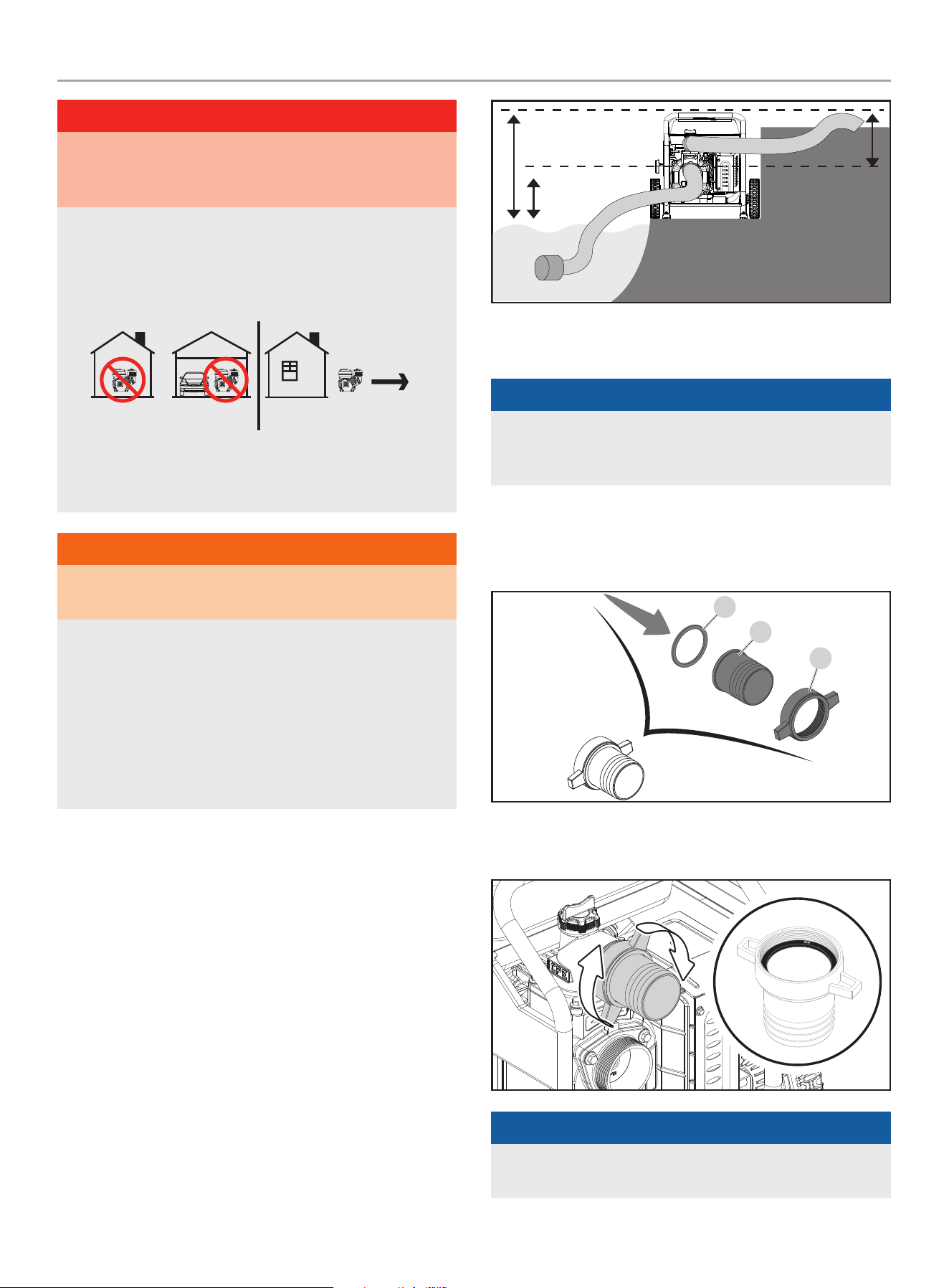
Place the water pump on a flat, level surface. The pump should
be placed close to the water level to ensure maximum pump
performance.
Pump output will be affected by the type, length, and size of the
suction and discharge hoses. The pumping height, also known as
the total head, is the distance from the water level to the point of
discharge. As this distance increases, pump output decreases.
The discharge capacity is greater than the suction capacity.
Therefore, it is important that the suction head is less than the
discharge head. The time required to draw water from the source
to the pump (self-priming time) can be decreased by minimizing
the suction head.
Total head
Suction head
Discharge head
connecting a hose Kit
NOTicE
Both the inlet and outlet ports are 3 in. (7.5 cm) NPT. Please
ensure the connectors to the suction and discharge hose are
3 in. (7.5 cm) NPT threaded.
Connect the Discharge hose (Blue)
1. Locate (1) of the following: outlet hose adapter (C), gasket (A),
and outlet hose fitting (B) and align for assembly.
A
b
c
2. Thread the assembled connector to the outlet fitting (top of
pump). Locate the blue “outlet” label on the pump.
NOTicE
Make sure the gasket is seated inside before threading the
adapter on.
17
100743 - 3 iN. (7.5 cM) SEMi-TRASh PUMP
OPERATiON
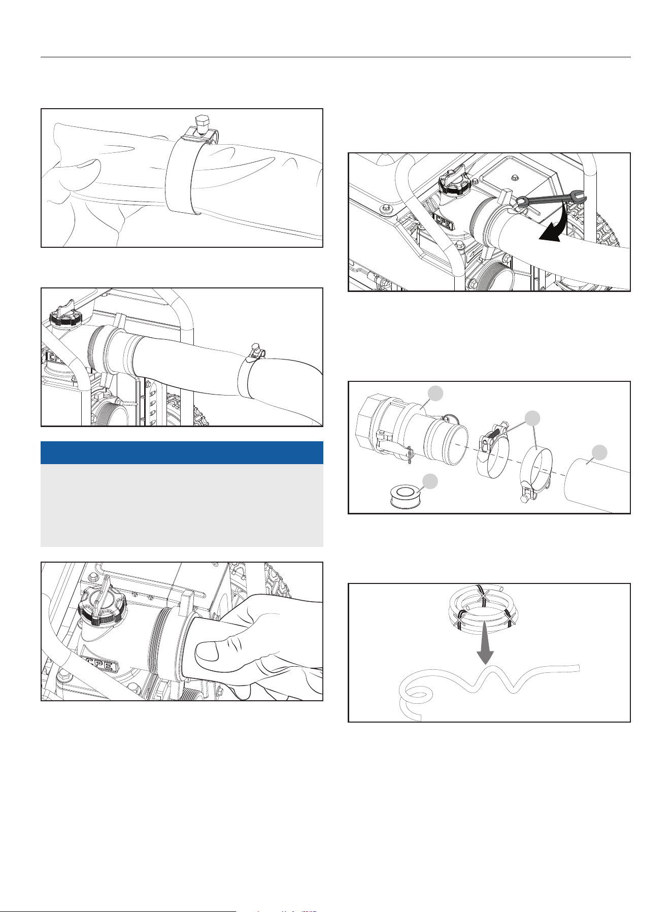
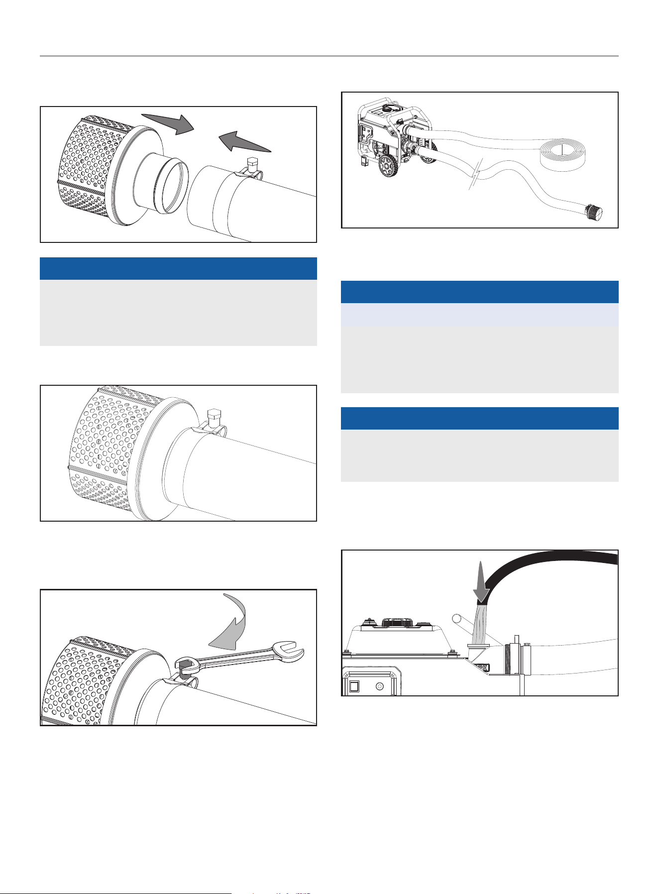
3. Locate and slide the silver colored hose clamp (marked 74-
79) over the blue outlet hose.
4. Slide the blue discharge hose over the outlet hose fitting.
NOTicE
You may use a small amount of dish soap on the outlet hose
fitting to help ease the outlet hose on the fitting. Work the
soap around the fitting with your finger. Then work the blue
hose on the outlet, by twisting and turning until it’s fully
seated.
5. Slide the hose clamp in place about midway on the outlet
hose adapter as shown. Tighten to 7.4±1.5 lbf-ft (10±2 Nm)
with a 13mm wrench. The hose clamp should be placed
behind the outlet adapter barbs on the smooth part of the
adapter.
Connect the Suction hose (Green) and Suction Filter
1. Locate the following: cam lock coupler (coupler and fitting
together) (A), 80-85 marked hose clamps (B), Teflon
®
tape
(C), green suction hose (D) and align for assembly.
A
b
c
D
2. Cut ties and uncoil the green hose and use some weight to
help straighten the hose out. Best to do this on a warmer day
in the sun.
18
100743 - 3 iN. (7.5 cM) SEMi-TRASh PUMP
OPERATiON
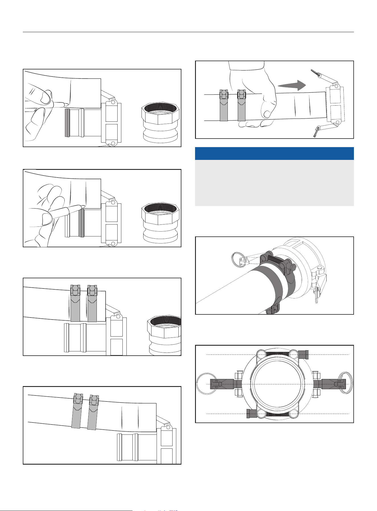
3. Separate the cam lock coupler and fitting. Align the green
hose to the coupler and mark the locations of the ribs on the
fitting.
4. Mark the second rib on the coupler on the hose.
5. Lay the green hose side by side and place the clamp marked
80-85 in their approximate location.
6. Slide the clamps back and start to assemble the green hose
to cam lock coupler.
7. Insert the threaded or quick coupler in the green rigid suction
hose until properly seated.
NOTicE
You may use a small amount of dish soap on the cam lock
coupler to help ease the green hose on the fitting. Work
the soap around the coupler with your finger. Then work the
green hose on the fitting, by twisting and turning until it’s fully
seated.
8. Slide the clamps marked 80-85 over cam lock coupler just
past the marks you made on the hose earlier.
9. Rotate and align the clamp bolts so you have clearance for
the cam levers to lock in place later.
19
100743 - 3 iN. (7.5 cM) SEMi-TRASh PUMP
OPERATiON
10. Tighten each clamp to 7.4±1.5 lbf-ft (10±2 Nm) with a 13mm
wrench. If you do not have a torque wrench, hand tight then
¼ turn past full tight.
11. Test connection is tight by twisting coupler in the hose to
make sure it doesn’t turn. If coupling turns, then tighten
clamps further until coupling won’t turn.
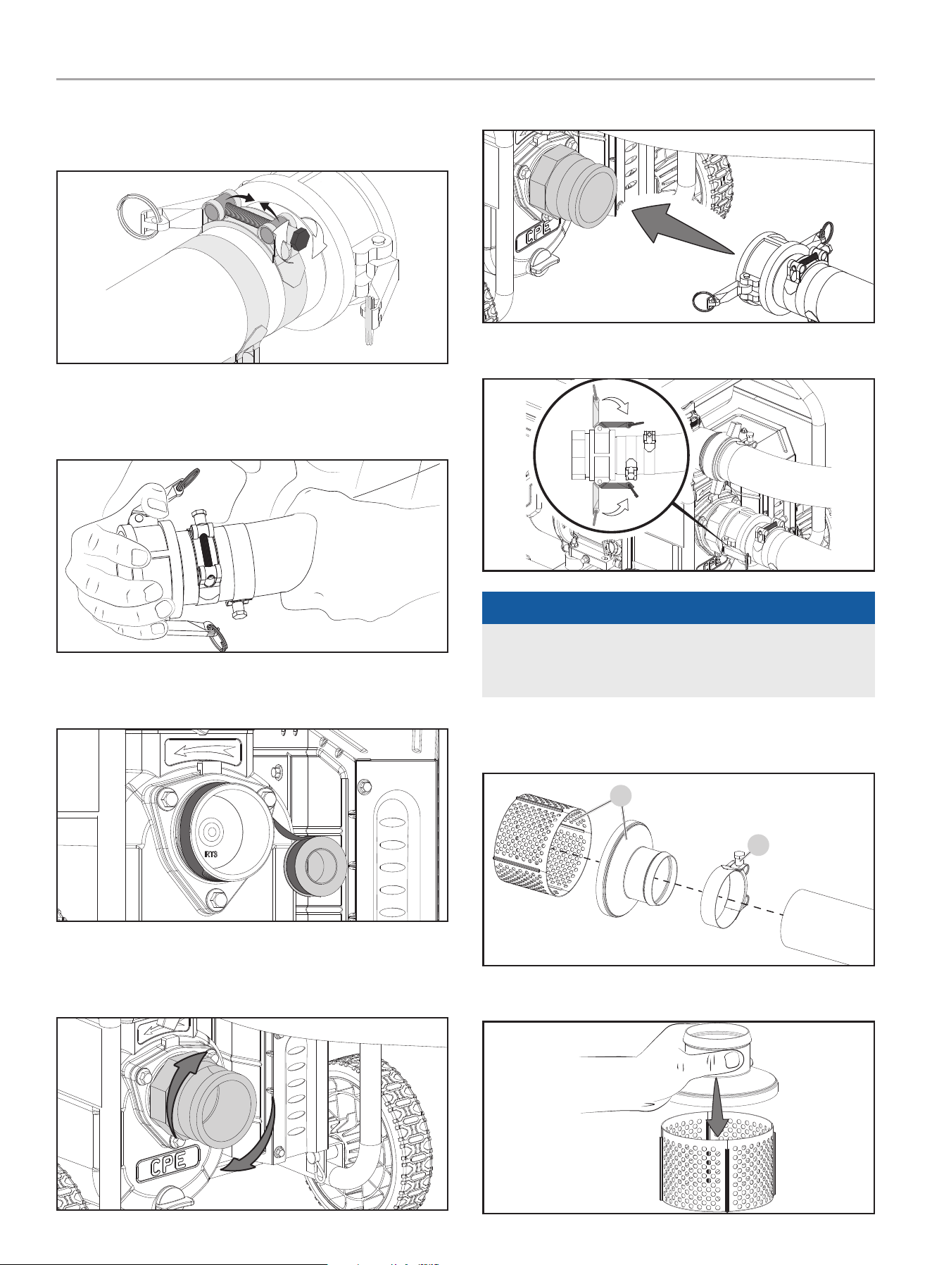
12. Wrap the green inlet clockwise with the Teflon
®
tape provided
with 4 complete wraps.
13. Thread the fitting over the tape and hand tighten. If you have
channel locks large enough, you can give it a ¼ turn past
hand tight.
14. Attach the cam lock coupler to the fitting.
15. Lock in place with the cam levers.
NOTicE
If the cam levers do not clamp down completely, rotate and
align the clamp bolts so you have clearance for the cam levers
to lock. See step 9 earlier.
16. Locate the following: filter (E) and 80-85 marked hose
clamp (F).
E
f
17. Snap the filter pieces together.
20
100743 - 3 iN. (7.5 cM) SEMi-TRASh PUMP
OPERATiON
18. Place the clamp marked 80-85 on the other end of the green
hose. Attach the strainer to the green suction hose.
NOTicE
You may use a small amount of dish soap on the filter to help
ease the green hose on the filter. Work the soap around the
filter with your finger. Then work the green hose on the filter,
by twisting and turning until it’s fully seated.
19. Slide the clamp just before the end of the green hose.
20. Tighten the clamp to 7.4±1.5 lbf-ft (10±2 Nm) with a 13mm
wrench. If you do not have a torque wrench, hand tight then
¼ turn past full tight.
21. You should have everything connected.
Priming the Pump
NOTicE
DO NOT run the pump dry.
Running the pump dry can destroy the pump seals and will void
the warranty. If the pump was running while dry, stop the engine
and allow it to cool thoroughly before filling the chamber with
water.
NOTicE
Ensure the priming plug is secure before pump operation, if not
secure the priming plug could be ejected and water or other
liquids could be pumped through the top of the outlet flange.
1. Remove the priming cap (top) and fill pump body to the very
top of outlet flange with water. Reinstall the priming plug. DO
NOT over tighten.
2. As the engine starts up, this will start the draw of liquid into
the pump. Located within the pump assembly is the one-
way valve. As you prime the pump housing this one-way flap
valve shuts off the opening to the suction hose. The priming
process is only required when the pump housing is not full of
water.
21
100743 - 3 iN. (7.5 cM) SEMi-TRASh PUMP
OPERATiON
before Starting the Engine
1. Route the suction hose so that the filter is immersed
completely in the water supply source.
2. DO NOT operate pump without the filter fully immersed.
3. DO NOT operate the pump without the filter attached to the
hose.
4. Secure the suction hose to keep it from moving once the
water pump is started.
5. Route the discharge hose to the desired location. Secure the
discharge hose to keep it from moving once the water pump
is started.
6. Place the water pump on a flat, level surface.
7. Check that the oil is at the full mark on the dipstick, and that
fuel has been added to the fuel tank.
8. Review the water pump assembly and ensure fittings are
properly secured and make sure there are no kinks, cuts, or
damage to hoses.
Starting the Engine
NOTicE
DO NOT run the pump without the unit primed and suction
hose in the water. Damage to equipment resulting from failure
to follow this instruction will void warranty.
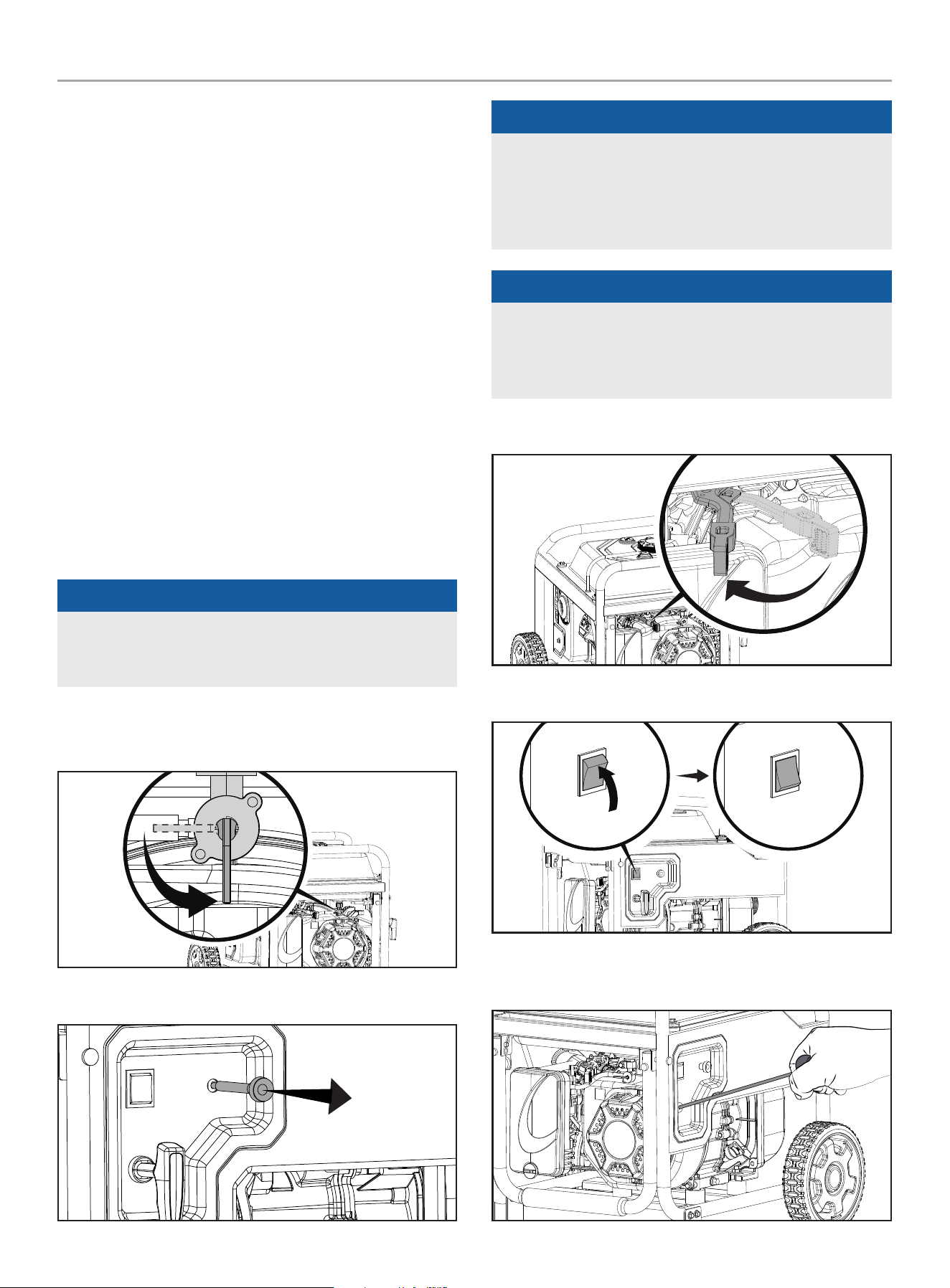
1. Make certain the water pump is on a flat, level surface.
2. Move the fuel valve to the ON position
3. Move the choke lever to the “CHOKE” position by pulling out.
NOTicE
Keep choke lever in “CHOKE” position for 2 pulls of the recoil
starter. After second pull, move choke lever to the “RUN”
position for up to the next 3 pulls of the recoil starter. Too
much choke leads to spark plug fouling/engine flooding due to
the lack of incoming air. This will cause the engine not to start.
NOTicE
If the engine starts but does not run make certain that the unit
is on a flat, level surface. The engine is equipped with a low oil
sensor that will prevent the engine from running when the oil
level falls below a critical threshold.
4. Move the throttle lever to the “FAST” position.
5. Press engine switch to “ON” position.
6. Pull the starter cord slowly until resistance is felt and then
pull rapidly.
22
100743 - 3 in. (7.5 cm) Semi-TraSh PumP
OPeraTiOn
WarninG
Rapid retraction of the recoil cord will pull hand and arm
towards the engine faster than you can let go. Unintentional
startup can result in entanglement, traumatic amputation or
laceration. Broken bones, fractures, bruises or sprains could
result.
7. As engine warms up, move the choke to “RUN” by pushing in
and adjust the throttle as needed
nOTice
Water pump performance can be adjusted using the throttle.
To decrease pump output, slide the throttle to the slow the
engine speed, towards “SLOW”. To increase it, slide the
throttle towards “FAST”
WarninG
DO NOT remove either top cap or bottom plug while the water
pump is on and running. Loss of pressure and suction will
occur. Injury may also occur.
Stopping the engine
nOTice
If the engine will not be used for a period of two (2) weeks or
longer, please see the Storage section for proper engine and
fuel storage.
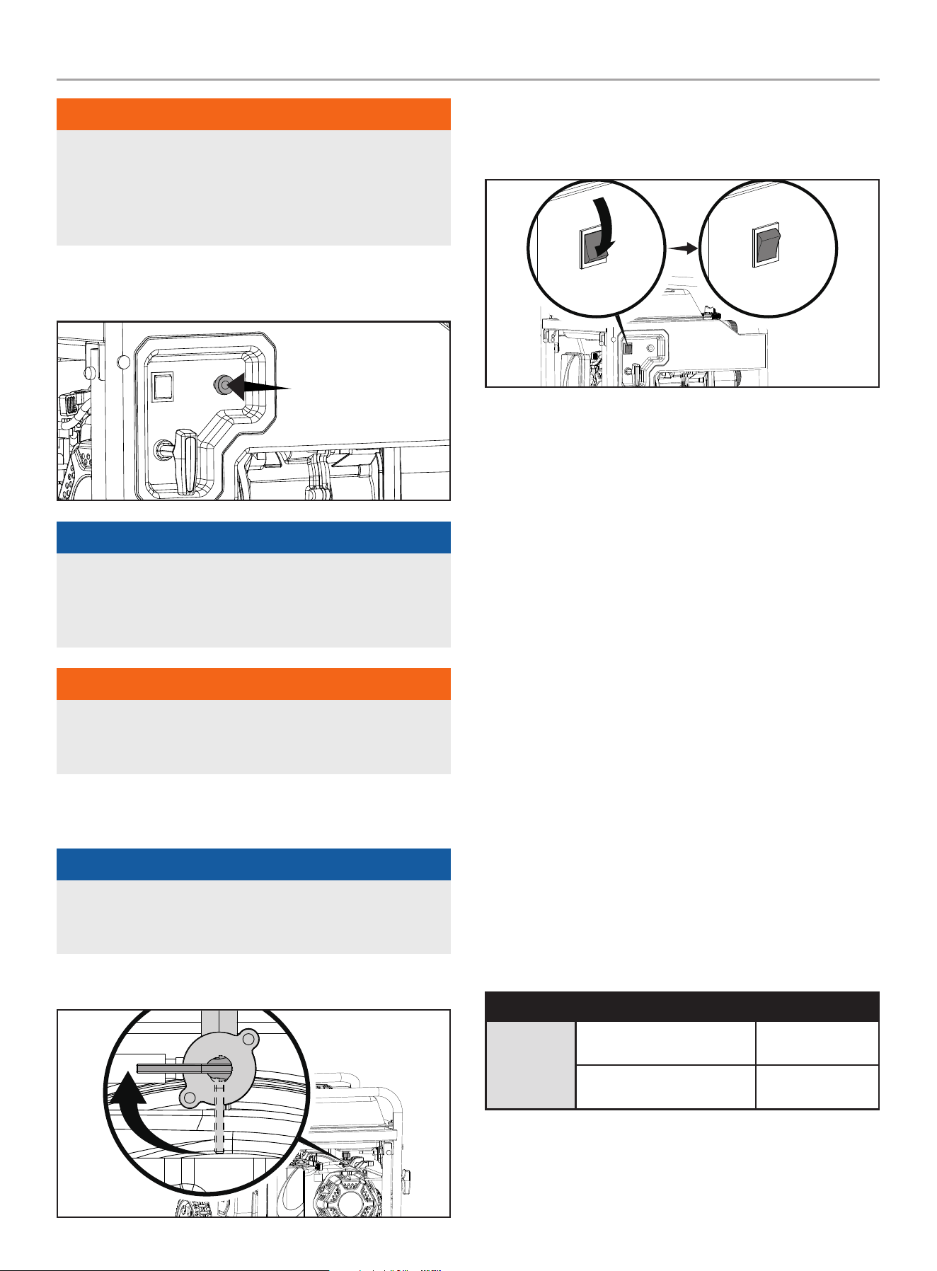
1. Turn the fuel valve to the “OFF” position.
2. Let the engine run until fuel starvation has stopped the
engine. This usually takes a few minutes.
3. Press the engine switch to the “OFF” position.
Important: Always ensure that the fuel valve and the engine
switch are in the “OFF” position when the engine is not in use.
Operation at high altitude
The density of air at high altitude is lower than at sea level.
Engine power is reduced as the air mass and air-fuel ratio
decrease. Engine power and water pump output will be reduced
approximately 3½% for every 1000 ft. of elevation above sea
level. This is a natural trend and cannot be changed by adjusting
the engine. At high altitudes increased exhaust emissions can
also result due to the increased enrichment of the air fuel ratio.
Other high altitude issues can include hard starting, increased fuel
consumption and spark plug fouling.
To alleviate high altitude issues other than the natural power
loss, CPE can provide a high altitude carburetor main jet. The
alternative main jet and installation instructions can be obtained
by contacting our Technical Support Team. Installation instructions
are also available in the Technical Bulletin area of the CPE website.
The part number and recommended minimum altitude for the
application of the high altitude carburetor main jet is listed in the
table below.
In order to select the correct high altitude main jet it is necessary
to identify the carburetor model. For this purpose, a code is
stamped on the side of the carburetor. Select the correct high
altitude jet part number corresponding to the carburetor code
found on your particular carburetor.
Carb. Code High Alt. Jet Part Number Altitude Range
16100-
Z2M0110-
00M0
16161-Z152210-0000
3000-6000ft
914-1829 m
16161-Z152010-0000
6000-8000ft
1829-2434 m
23
100743 - 3 iN. (7.5 cM) SEMi-TRASh PUMP
MAiNTENANcE
WARNiNG
Operation using the alternative main jet at elevations lower
than the recommended minimum altitude can damage the
engine. For operation at lower elevations, the originally
supplied standard main jet must be used. Operating the
engine with the wrong engine configuration at a given altitude
may increase its emissions and decrease fuel efficiency and
performance.
MAiNTENANcE
Make certain that the water pump is kept clean and stored
properly. Only operate the unit on a flat, level surface in a clean,
dry operating environment. DO NOT expose the unit to extreme
conditions, excessive dust, dirt, moisture or corrosive vapors.
WARNiNG
Never operate a damaged or defective water pump.
WARNiNG
Improper maintenance will void your warranty.
NOTicE
For emission control devices and systems, read and
understand your responsibilities for service as stated in the
Emission Control Warranty Statement of this manual.
The owner/operator is responsible for all periodic maintenance.
Complete all scheduled maintenance in a timely manner.
Correct any issue before operating the water pump.
For service or parts assistance, contact our
Technical Support Team at 1-877-338-0999.
cleaning the Water Pump
cAUTiON
DO NOT spray water pump with water.
Water can contaminate the fuel system and can enter the
engine through the cooling slots and damage the engine.
1. Use a damp cloth to clean exterior surfaces of the water
pump.
2. Use a soft bristle brush to remove dirt and oil.
3. Use an air compressor (25 PSI) to clear dirt and debris from
the water pump
4. Inspect all air vents and cooling slots to ensure that they are
clean and unobstructed.
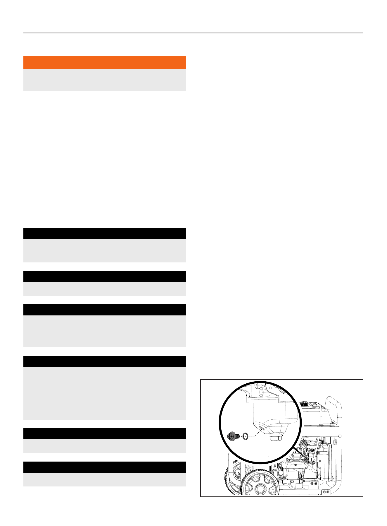
changing the Engine Oil
Change oil when the engine is warm. Refer to the oil specification
to select the proper grade for your operating environment.
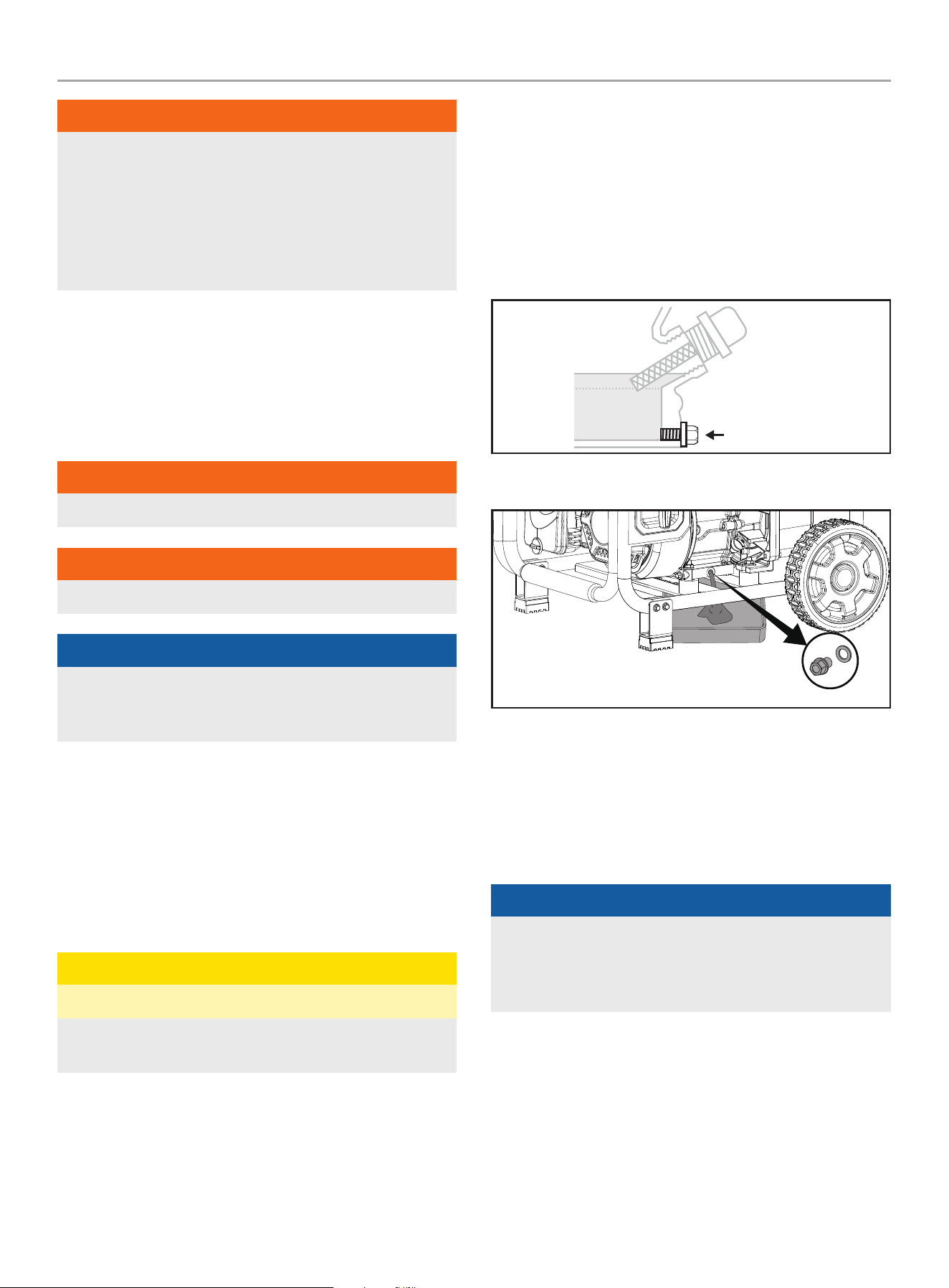
1. Remove the oil drain bolt with a 10 mm socket
(not included) and extension.
DRAIN BOLT
2. Allow the oil to drain completely into an appropriate container.
3. Replace the oil drain bolt. Tighten to 8.8 lbf-ft − 10.3 lbf-ft
(12-14 Nm).
4. Add oil according to “Add Engine Oil” in Assembly section.
DO NOT OVERFILL. Oil not included for routine maintenance.
5. Dispose of used oil at an approved waste management
facility.
NOTicE
Once oil has been added, a visual check should show oil
about 1-2 threads from running out of the fill hole. If using the
dipstick to check oil level, DO NOT screw in the dipstick while
checking.
24
100743 - 3 iN. (7.5 cM) SEMi-TRASh PUMP
MAiNTENANcE
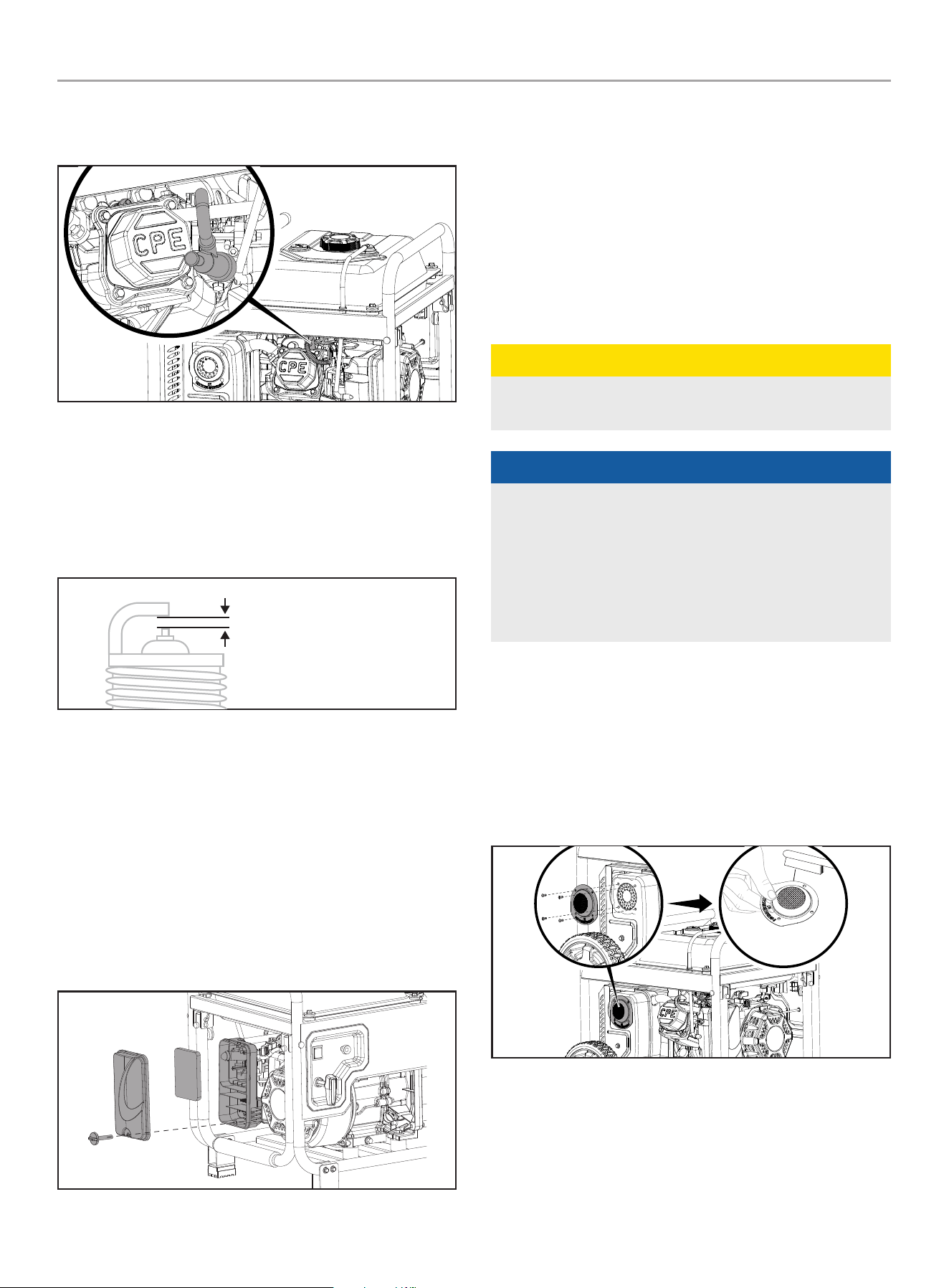
cleaning and Adjusting the Spark Plug(s)
1. Remove the spark plug cable from the spark plug.
2. Use a spark plug socket tool (not included), or a 13/16 in.
(21 mm) (not included) socket to remove the plug.
3. Inspect the electrode on the plug. It must be clean and not
worn to produce the spark required for ignition.
4. Make certain the spark plug gap is set within limits. Refer to
the Specifications section for values.
SPARK PLUG GAP
5. Refer to the spark plug section on the Specifications page
when replacing the plug.
6. Carefully thread the plug into the engine.
7. Use the spark plug socket tool (not included), or a 13/16 in.
(21 mm) (not included) socket to install the plug.
8. Attach the spark plug wire to the plug.
cleaning the Air filter
1. Remove the cover holding the air filter (foam element) to the
assembly.
2. Remove the foam element.
3. Wash the foam element in liquid detergent and water.
Squeeze thoroughly dry.
4. Saturate in clean engine oil.
5. Squeeze in a clean, absorbent cloth to remove all excess oil.
6. Place the air filter (foam element) back into the assembly.
7. Reattach the air filter cover.
cleaning the Spark Arrestor
cAUTiON
Failure to clean the spark arrestor will result in degraded
engine performance.
NOTicE
Federal and local laws and administrative requirements
indicate when and where spark arrestors are required. When
ordered, spark arrestors are required for operation of this
water pump in National Forest lands. In California, this water
pump must not be used on any forest-covered land, brush-
covered land, or grass-covered land unless the engine is
equipped with a spark arrestor.
1. Allow the engine to cool completely before servicing the spark
arrestor (if equipped).
2. Remove the screws holding the cover plate which retains the
spark arrestor screen to the muffler.
3. Remove the spark arrestor screen.
4. Carefully remove the carbon deposits from the spark arrestor
screen with a wire brush.
5. Replace the spark arrestor if it is damaged.
6. Position the spark arrestor on the muffler and attach with the
screws.
25
100743 - 3 iN. (7.5 cM) SEMi-TRASh PUMP
STORAGE
Adjusting the Governor
WARNiNG
Tampering with the factory set governor will void your
warranty.
The air-fuel mixture is not adjustable. Tampering with the governor
can damage your water pump and will void your warranty. Contact
our Technical Support Team at 1-877-338-0999 for all other
service and/or adjustment needs.
Maintenance Schedule
Follow the service intervals indicated in the following maintenance
schedule.
Service your water pump more frequently when operating in
adverse conditions.
Contact our Technical Support Team at 1-877-338-0999 to locate
the nearest CPE certified service dealer for your water pump or
engine maintenance needs.
EVERY 8 hOURS OR PRIOR TO EaCh USE
Check oil level
Clean around air intake and muffler
FIRST 5 hOURS
Change oil
EVERY 50 hOURS OR EVERY SEaSON
Clean air filter
Change oil if operating under heavy load or in hot
environments
EVERY 100 hOURS OR EVERY SEaSON
Change oil
Clean/adjust spark plug
Check/adjust valve clearance*
Clean spark arrester
Clean fuel tank and filter*
EVERY 250 hOURS
Clean combustion chamber*
EVERY 3 YEaRS
Replace fuel line*
* To be performed by knowledgeable, experienced owners or CPE certified service
centers.
STORAGE
Refer to the Maintenance section for proper cleaning instructions.
Water Pump Storage
1. Allow the water pump to cool completely before storage.
2. Turn off the fuel supply at the fuel valve.
3. Clean the water pump according to the instructions in the
Maintenance section.
4. Drain the pump chamber thoroughly.
5. Once the pump is dry, spray WD-40 or similar product into
the pump housing through all ports and drainage hole.
6. Store the unit in a clean, dry area out of direct sunlight.
Short Term Engine Storage (Up to 30 Days)
1. Allow the engine to cool completely before storage.
2. Clean engine according to the Maintenance section.
3. To extend the fuel storage life add a properly formulated fuel
stabilizer to the fuel tank.
4. Ensure the fuel valve is in the “OFF” position.
Mid Term Engine Storage ( 30 Days – 1 year)
1. Add a properly formulated fuel stabilizer to the tank.
2. Run the engine for a few minutes so the treated fuel cycles
through the fuel system and carburetor.
3. Turn the fuel valve to the “OFF” position.
4. Let the engine run until fuel starvation has stopped the
engine. This usually takes a few minutes. The engine needs
to cool completely before cleaning and storage.
5. Use a funnel (and appropriate hose if necessary) under the
carburetor drain bolt to avoid spillage. Be sure to properly
dispose of the drained gasoline according to local regulations
or guidelines.

26
100743 - 3 iN. (7.5 cM) SEMi-TRASh PUMP
STORAGE
6. Clean the engine according to the Maintenance section.
7. Change the oil.
8. Remove the spark plug and pour about 1⁄2 oz. (14.9 mL) of oil
into the cylinder. Crank the engine slowly to distribute the oil
and lubricate the cylinder.
9. Reattach the spark plug.
Long Term Storage
WARNiNG
Never store the water pump indoors or next to appliances
where there is a source of heat or open flame, spark or pilot
light because they can ignite gasoline vapors. DO NOT store a
water pump near fertilizer or any corrosive material. Even with
an empty gas tank, gasoline vapors could ignite.
DANGER
Engine exhaust contains odorless and colorless carbon
monoxide gas.
To avoid accidental or unintended ignition of the product
during periods of storage, the following precautions should be
followed:
– When storing the water pump for short or long periods of
time make sure that the engine switch (where applicable)
and the fuel valve are set in the “OFF” position.
NOTicE
Our engines work well with 10% or less ethanol blend
gasoline. When using ethanol-gasoline blends there are some
issues worth noting:
– Ethanol-gasoline blends can absorb more water than
gasoline alone.
– These blends can eventually separate, leaving water or a
watery goo in the tank, fuel valve and carburetor.
– With gravity-fed supplies, the compromised gasoline can
be drawn into the carburetor and cause damage to the
engine and/or potential hazards.
– There are only a few suppliers of fuel stabilizer that are
formulated to work with ethanol-gasoline blends.
– Any damages or hazards caused by using improper
gasoline, improperly stored gasoline, and/or improperly
formulated stabilizers, are not covered by manufacturer’s
warranty.
It is advisable to always shut off the gasoline supply, run the
engine to starvation and drain the tank when the equipment is
not in use for more than 30 days.
Protect your water pump from freezing.
1. Apply all storage instructions from previous sections.
2. Make sure water pump is free of all water before storing for
winter.
3. In order to prevent the pump from freezing you will need to
insert RV antifreeze.
4. You will need approximately 6 oz. (177.4 mL) of RV antifreeze,
a funnel, and approximately 12 in. (30.5 cm) of garden hose
or equivalent.
5. Pour the antifreeze into the funnel connected to the pump
inlet or priming cap (top) with a small hose, then pull on the
recoil starter. Pull the recoil several times to circulate the
antifreeze.
27
100743 - 3 iN. (7.5 cM) SEMi-TRASh PUMP
SPEcificATiONS
SPEcificATiONS
Water Pump Specifications
Water Pump Type .......................................Semi-trash
Port Diameter (in./cm) ........................................ 3 / 7.5
Port Connection Type .......................................... NPT
Discharge Rate (gal/min - L/min) ........................ 264/1000
Total Head (ft/m) ............................................. 92/28
Suction Head (ft/m) .......................................... 26 / 8
Solids Handling (in/mm) .....................................0.75/19
Impeller Material .......................................... Cast Iron
Volute Material ............................................ Cast Iron
Self-Priming ..................................................... Yes
Hose Kit Included ................................................ Yes
Discharge Hose Length (ft/m) ...............................25/ 7.6
Suction Hose Length (ft/m) ..................................12/3.7
Overall Dimensions
Net Weight ............................................. 90 lb. (41kg)
Length ..............................................21.7 in. (55 cm)
Width .................................................22 in. (56 cm)
Height ...............................................21.3 in. (54 cm)
Engine Specifications
Model ........................................................ R224P
Displacement .................................................224 cc
Type ................................................... 4-Stroke OHV
Start Type .................................................... Recoil
Engine Oil Specifications
DO NOT OVERFILL.
Type ................................................ See chart below
Capacity ........................................ 16.9 fl. oz (500 ml)
-20 0 20 40 60
Ambient temperature
Recommended Engine Oil Type
80 100 120
-28.9
°F
°C -17.8 -6.7 4.4 15.6 26.7 37.8 48.9
10W-30
5W-30 Synthetic
10W-405W-30
NOTicE
Weather will affect engine oil and engine performance. Change
the type of engine oil used based on weather conditions to suit
the engine needs.
fuel Specifications
Use regular unleaded gasoline with a minimum octane rating of 87
and an ethanol content of less than 10% by volume. DO NOT USE
E15 or E85. DO NOT OVERFILL.
Gasoline Capacity .................................... 3 gal. (11.5 L)
Spark Plug Specifications
OEM Type .............................................. NHSP F6RTC
Replacement Type ...................... NGK BPR6ES or equivalent
Gap ..................................0.028-0.031 in. (0.7-0.8 mm)
Valve Specifications
Intake Clearance .............. 0.0004 - 0.0006 in. (0.1-0.15 mm)
Exhaust Clearance ............0.0006 - 0.0008 in. (0.15-0.2 mm)
NOTicE
A technical bulletin regarding valve adjustment procedures is
available at www.championpowerequipment.com.
important Message About Temperature
Your product is designed and rated for continuous operation at
ambient temperatures up to 104°F (40°C). When your product is
needed it may be operated at temperatures ranging from
2°F (-10°C) to 122°F (50°C) for short periods of time. If exposed
to temperatures outside this range during storage, it should be
brought back within this range before operation. In any event, the
product must always be operated outdoors, in a well-ventilated
area and away from doors, windows and vents.
28
100743 - 3 iN. (7.5 cM) SEMi-TRASh PUMP
SPEcificATiONS
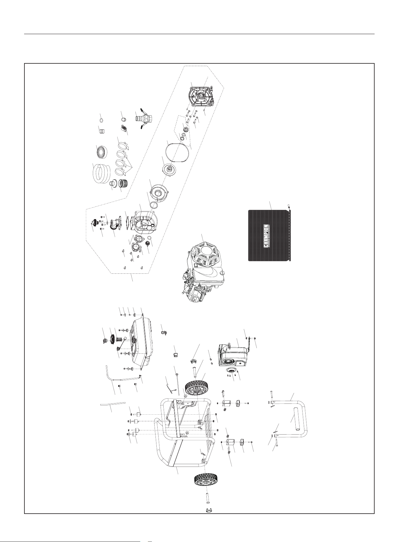
Parts Diagram - frame and Engine
42
44
50
51
46
45
54
53
52
43
44
49
48
47
69
68
70
71
62
64
65
66
67
58
59
61
60
57
56
55
9
8
7
5
6
4
3
2
10
11
12
13
15
16
17
18
19
20
21
32
31
8
27
26
30
29
28
35
34
33
26
40
38
22
23
24
39
12
25
1
75
63
14
36
37
33
33
28
41
72
73
74
76
77
29
100743 - 3 iN. (7.5 cM) SEMi-TRASh PUMP
SPEcificATiONS
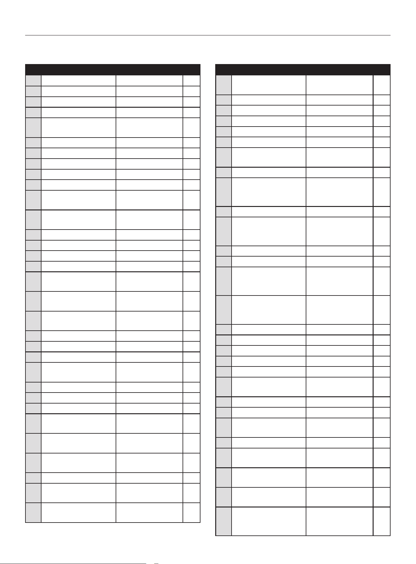
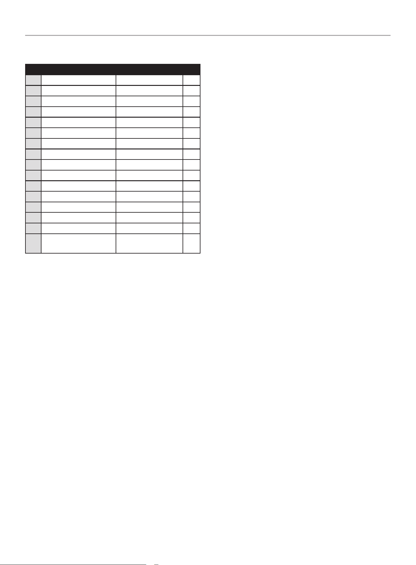
Parts List
# Part Number Description Qty.
1 R225MP000Q3-CMP304 Engine, 224cc 1
2 15150-Y1Z0110-00A0 Valve, One Way 1
3 16730-Z810110-0001 Fuel Tank Cap 1
4 16652-Z0M0110-00A1 Fuel Filter 1
5 90007-0625-0301
Hexagon Flange Bolt,
M6 x 25, Black Zinc
4
6 90408-Y020110-0006 Flat Washer, Black Zinc 4
7 90683-Y020210-0000 Bushing 4
8 16601-Y020120-0001 Rubber, Fuel Tank 6
9 16600-V580110-L400 Fuel Tank Assembly 1
10 37200-Y1Y0110-00A1 Fuel Gauge 1
11 16804-V580110-0001
Fuel Steam Rubber
Hose
1
12 90698-Y1Z0110-0001
Protective Rubber
Sleeve
2
13 90685-Z030410-0001 Clamp, Ø10.7 x 0.6 x 8 1
14 30431-YBW0210-0000 Rubber Sleeve 1
15 16750-Y900111-0001 Fuel Valve Assembly 1
16 90406-0800-E109 Flat Washer 2
17 51005-V580110-0000
Vibration Mount 1,
Frame
2
18 51005HV090210-0000
Vibration Mount 2,
Frame
2
19 16080-V580110-0001
Choke Handle
Subassembly
1
20 35541-V330310-0000 Engine Stop Wire 1
21 35160-Y450110-0000 Switch Assembly 1
22 44001-V580110-L401 Cover, Hub Decorated 2
23 44020-V580110-0300
Roll Pin, L=96, Black
Zinc
2
24 44110-V580110-0000 Wheel 2
25 90722-Y9X0110-0000 End Plug 2
26 90583-YGK0110-03A0 R Pin, Black Zinc 4
27 51100-V530210-H7A0
Frame Assembly, Ø25,
510 x 395 x 450
1
28 90305-0600-0301
Hexagon Flange Nut,
M6, Black Zinc
6
29 90001-0640-0301
Hexagon Flange Bolt,
M6 x 40, Black Zinc
4
30 51016-V580110-H700 Support Leg 2
31 51014HY3Y0110-0000
Vibration Mount,
Support Leg
2
32 90001-0625-0306
Hexagon Flange Bolt,
M6 x 25, Black Zinc
2
# Part Number Description Qty.
33 90305-0800-0102
Hexagon Flange Nut,
M8, Blue White Zinc
9
34 53438-V580110-QCA0 Pin Shaft, Ø8 x 65 2
35 54101-Y9P0110-0001 Handle Sheath 1
36 54110-V580110-H7A0 Handle, Ø25 x 1.2 1
37 18250-V580110-0000 Spark Arrestor 1
38 90124-Y2C0110-0100 Screw,ST4.2×9.5 4
39 90303-0800-3101
Nut, M8, Blue White
Zinc
2
40 18100-V580110-H3A0 Muffler Assembly 1
41 90001-0835-0102
Hexagon Flange Bolt,
M8 x 35, Blue White
Zinc
1
42 70107-V580110-L400 Plug, Outlet 1
43 90001-1025-51
Hexagon Flange Bolt,
M10 x 25, Blue White
Zinc
4
44 70122-V260110-0000 Sealing Ring, Plug 2
45 70108-V340510-0K00 Outlet 1
46 90001-1030-01
Hexagon Flange Bolt,
M10 x 30, Blue White
Zinc
4
47 90001-1020-51
Hexagon Flange Bolt,
M10 x 20, Blue White
Zinc
3
48 70116-V340210-0K00 Inlet 1
49 70115-V340110-0000 Inlet Gasket 1
50 70107-V330110-L400 Plug, Pump Body 1
51 70109-V340110-000 Outlet Gasket 1
52 70105-V340810-0K00 Pump Body 1
53 70104-V340110-0000
Sealing Ring, Whorl
Case Seal
1
54 70103-V340110-0000 Whorl Case 1
55 70102-V340210-0000 Water Pump Impeller 1
56 70119-V340110-0000
Sealing Ring, Water
Pump Joint
1
57 70125-V260210-0000 Sealing Ring, Impeller 1
58 70309-V330110-0000
Friction-Piece, Silicon
Carbide
1
59 70300-V330110-0000
Water Seal, Silicon
Carbide
1
60 70300HV330110-0000
Seal Assembly,
Mechanism
1
61 90001-V020110-0000
Hexagon Flange Bolt,
5/16-24UNF, L=60,
Blue White Zinc
4
30
100743 - 3 iN. (7.5 cM) SEMi-TRASh PUMP
SPEcificATiONS
Parts List
# Part Number Description Qty.
62 90409-V260110-0000 Sealing Ring, Bolt 4
63 90505-0618-00 Pin 2
64 70118-V340110-0K00 Water Pump Joint 1
65 70100-V530110-WT00 Water Pump Assembly 1
66 70113-V270210-0000 Filter Cover 1
67 70114-V270310-0000 Filter 1
68 70400-V530210-0200 Hose Clamp, Ø80-Ø85 3
69 70400-V530110-0100 Hose Clamp, Ø74-Ø79 1
70 70111-V270710-0K00 Outlet hose adapter 1
71 93161-V580110-0000 Teflon Tape 1
72 70134-V530110-0P00 Cam Lock Coupler 1
73 71108-V530110-0000 Suction Hose, Green 1
74 71311-V530110-0000 Discharge Hose, Blue 1
75 70112-V340210-0000 Outlet hose fitting 1
76 70131-V270310-0000 Gasket, Hose Coupler 1
77 94026-V530110-00E0
Accessory Bag, 1000 x
730 mm
1
31
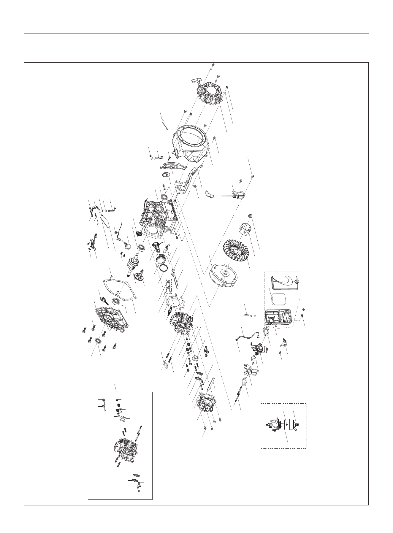
100743 - 3 iN. (7.5 cM) SEMi-TRASh PUMP
SPEcificATiONS
Engine Parts Diagram
1
1
2
3
4
5
6
7
8
9
10
11
12
13
14
15
16
17
18
19
20
21
22
23
24
25
26
27
28
29
30
31
32
33
34
35
36
37
38
39
40
41
42
43
48
49
49
50
51
52
53
54
55
56
57
58
59
60
61
62
62
62
62
63
64
65
66
67
67
68
69
70
71
72
73
74
75
76
77
78
80
81
82
83
84
85
86
79
44
45
46
47
87
5
6
7
42
29
8
9
11
13
21
22
14
12
88
89
90
91
32
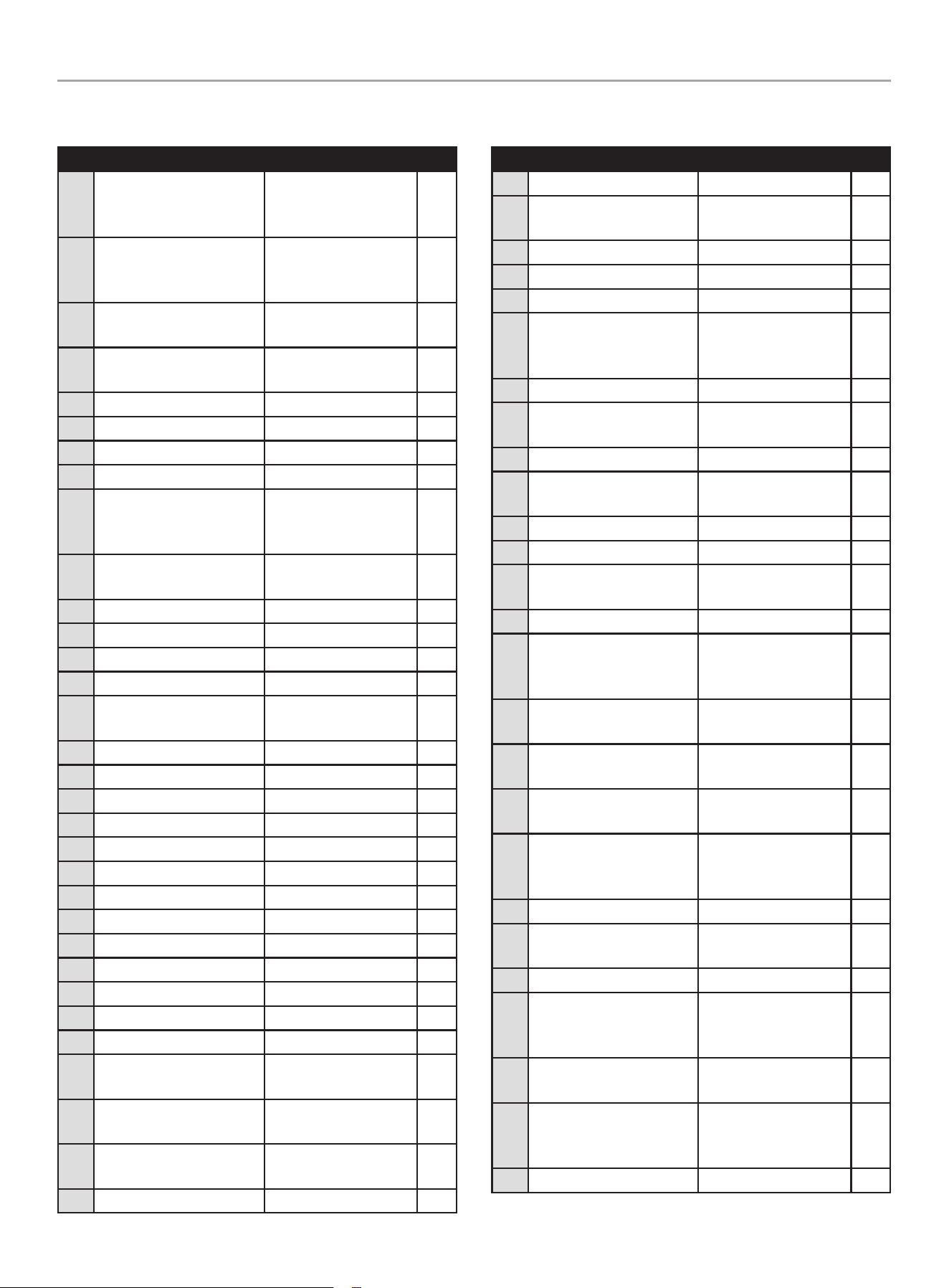
100743 - 3 iN. (7.5 cM) SEMi-TRASh PUMP
SPEcificATiONS
Engine Parts List
# Part Number Description Qty.
1 90001-0612-0101
Hexagon Flange Bolt,
M6 x 12, Blue White
Zinc
8
2 12410-Z440110-0001
Cylinder Head Cover
Subassembly, Blue
White Zinc
1
3 17004-Z510110-0001
Breather Tube, Ø8 x
Ø12 x 100
1
4 12004-Z440110-00A0
Cylinder Head Cover
Gasket
1
5 14312-Z010110-0000 Valve Lock Nut 2
6 14314-Z010110-0000 Valve Adjusting Nut 2
7 14311-Z010110-0000 Valve Rocker 2
8 14313-Z010110-0000 Valve Adjusting Bolt 2
9 14090-Z010110-0000
Lifter Stopper Plate
Subassembly, Blue
White Zinc
1
10 12003-Z010110-0001
Cylinder Head Bolt, M8
x 60, Blue White Zinc
4
11 12109-Z810110-0000 Valve Lock Clamp 4
12 12112-Z810210-0000 Valve Spring Set 2
13 12103-Z010110-0000 Valve Spring 2
14 12101-Z810210-0000 Seal Guide 1
15 12140-Z810210-0BA0
Cylinder Head
Subassembly
1
16 30010-Z010110-0000 Spark Plug 1
17 12131-Z530320-0000 Cylinder Head Gasket 1
18 90502-1114-00 Pin, 11 x 14 2
19 14071-Z440110-0000 Valve Lifter 2
20 12110-Z810120-0099 Valve Set 1
21 12121-Z810120-0000 Exhaust Valve 1
22 12111-Z810110-0000 Intake Valve 1
23 14081-Z040110-0000 Valve Tappet 2
24 13200-Z140210-00A9 Piston Ring Assembly 1
25 13122-Z510210-0000 Piston Pin Clip 2
26 13111-Z810120-00A0 Piston 1
27 13121-Z810110-0000 Piston Pin, Ø13 x 45.9 1
28 13010-Z810210-00A0 Connecting Rod 1
29 90204-Z010210-0000
Stud, M6 x 96, Black
Zinc
2
30 16002-Z050110-0000
Carburetor Insulator
Gasket
1
31 16003-Z010110-0000
Carburetor Insulator
Plate
1
32 16001-Z010110-0000 Carburetor Gasket 1
# Part Number Description Qty.
33 16100-Z2M0110-00M0 Carburetor Assembly 1
34 90686-Z510110-00M1
Fuel Pipe, Ø4.5 x Ø8.5
x 190
1
35 90685-Z030610-01A1 Clamp, Ø8 x 7 x 0.6 2
36 17001-Z010110-0000 Air Cleaner Gasket 1
37 17100-Z810510-0000 Air Cleaner 1
38 90001-0612-0101
Hexagon Flange Bolt,
M6 x 12, Blue White
Zinc
1
39 17003-Y110130-0000 Air cleaner Support 1
40 90305-0600-33
Hexagon Flange Nut,
M6, Black Zinc
2
41 17151-Z300310-00A0 Air Cleaner Element 1
42 90203-Z010110-0000
Stud, M8 x 34, Black
Zinc
2
43 18001-Z440110-0000 Exhaust Gasket 1
44 90502-0912-00 Pin, 9 x 12 2
45 15010-Z290110-L401
Oil Dipstick
Subassembly
1
46 11411-Z441310-0BA0 Crankcase Cover 1
47 90001-0832-0101
Hexagon Flange Bolt,
M8 x 32, Blue White
Zinc
6
48 11310-Z810210-0BA0
Crankcase
Subassembly
1
49 90682-Z300110-0001
Oil Seal, Ø25 x Ø41.25
x 6
2
50 90408-Z010110-0000
Washer, Ø10 x Ø15.8
x 1.5
2
51 11007-Z010110-0001
Drain Plug Bolt, M10
x1.25 x15, Blue White
Zinc
2
52 16061-Z010110-0000 Governor Arm 1
53 90408-Z010210-0000
Washer, Ø6.2 x Ø15
x 0.6
1
54 90501-Z010110-0001 Pin, Blue White Zinc 1
55 16070-Z010110-0001
Governor Support
Subassembly, Blue
White Zinc
1
56 90305-0600-3101
Hexagon Flange Nut,
M6, Blue White Zinc
1
57 16072-Z010110-0001
Governor Support Bolt,
M6 x 21, Blue White
Zinc
1
58 16063-Z010310-0100 Governor Spring 1
33
100743 - 3 iN. (7.5 cM) SEMi-TRASh PUMP
SPEcificATiONS
# Part Number Description Qty.
59 16062-Z010110-0001
Governeor Rod, Blue
White Zinc
1
60 16012-Z010310-0000
Throttle Valve
Returning Spring
1
61 16520-Z440410-0101
Throttle Control
Assembly, Blue White
Zinc
1
62 90001-0610-0101
Hexagon Flange Bolt,
M6 x 10, Blue White
Zinc
5
63 37060-Z010120-0001
Engine oil Sensor, W/O
Nut
1
64 90001-0614-01
Hexagon Flange Bolt,
M6 x 14, Blue White
Zinc
2
65 90305-Z010210-0101
Hexagon Flange Nut,
M10, Blue White Zinc
1
66 16400-Z810210-0000
Governor Gear
Assembly
1
67 90547-0205-00 Bearing 2
68 13510-Z440410-0000 Flywheel Subassembly 1
69 19352-Z440110-0001 Impeller 1
70 28002-Z0L0110-0000
Starter Pulley, Blue
White Zinc
1
71 13501-Z010110-0000
Flywheel Nut, M14 x
1.5, Blue White Zinc
1
72 30400-Z440410-0001 Ignition Coil 1
73 90001-0625-01
Hexagon Flange Bolt,
M6 x 25, Blue White
Zinc
2
74 19304-Z010610-0001 Cylinder Body Shroud 1
75 90684-Z010510-0000 Clip 1
76 19340-Z011010-0000 Lower Shield 1
77 90001-0616-01
Hexagon Flange Bolt,
M6 x 16, Blue White
Zinc
1
78 37050-Z010210-0001
Oil Protector, Blue
White Zinc
1
79 11001-Z440110-00A0 Crankcase Gasket 1
80 28110-Z010610-L400 Shroud 1
81 28200-Z141010-H301
Recoil Starter
Assembly
1
82 90408-0600-03 Washer, Black Zinc 3
83 90001-0608-03
Hexagon Flange Bolt,
M6 x 8, Black Zinc
3
84 30009-Z010210-0000 Grounding Wiring 1
85 14200-Z810310-0000 Camshaft Assembly 1
86 13300-Z811910-0000 Crankshaft Assembly 1
# Part Number Description Qty.
87 210P-001
Cylinder Head
Subassembly
1
88
16161-Z152410-0000 Main Jet, Standard 1
16161-Z152210-0000
Main Jet, Altitude
3000-6000 Feet
/
16161-Z152010-0000
Main Jet, Altitude
6000-8000 Feet
/
89 16112-Z010110-0000 Seal Ring, Float 1
90 90681-Z010610-0000 Seal Ring 1
91 30431-Y020110-0001 Rubber Sleeve 1
34
100743 - 3 iN. (7.5 cM) SEMi-TRASh PUMP
TROUbLEShOOTiNG
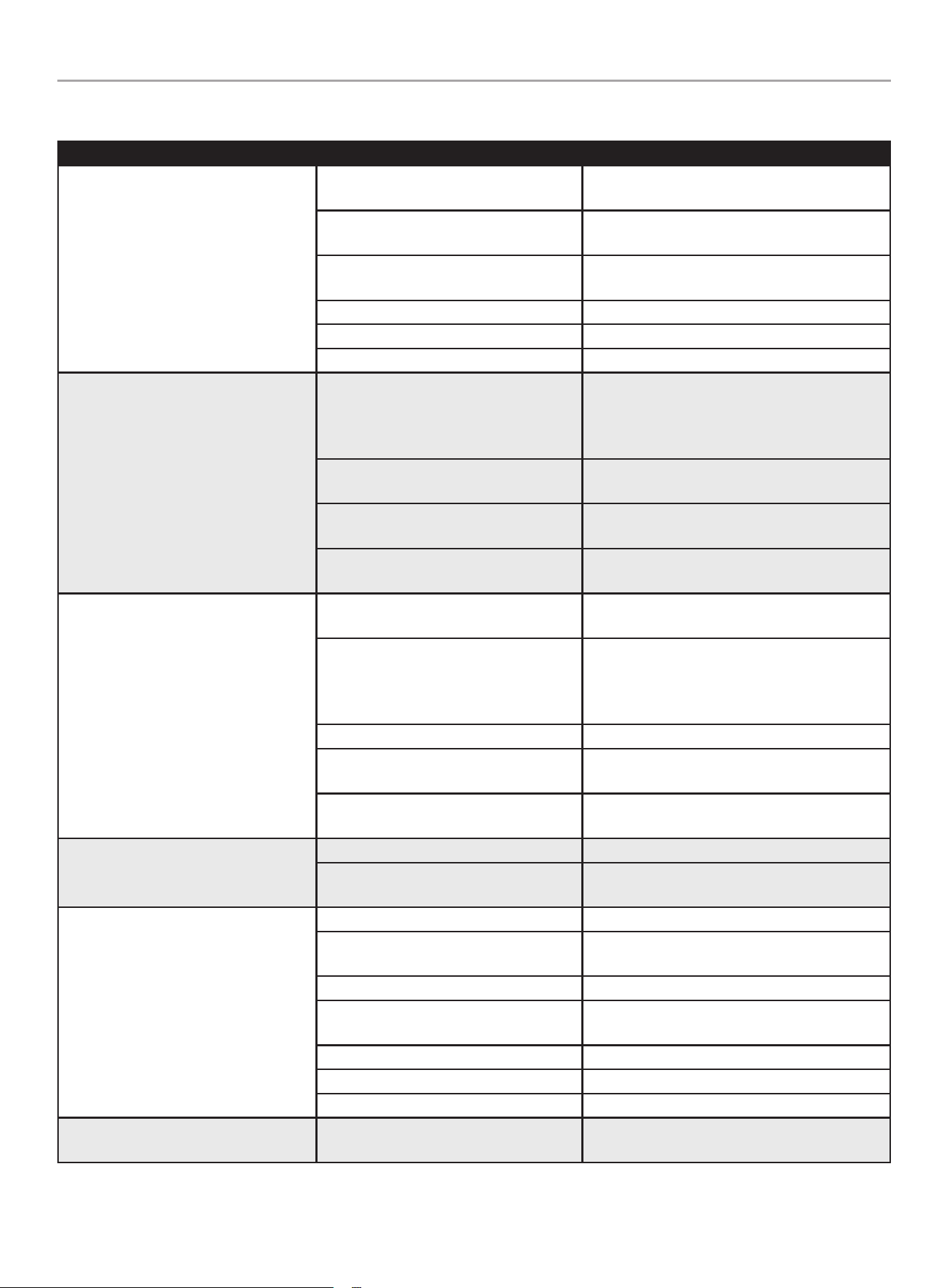
TROUbLEShOOTiNG
Problem Cause Solution
Pump will not start.
No fuel.
Allow engine to cool for 2 minutes, then fill fuel
tank.
Low oil.
Fill or check oil is to the proper level; place water
pump on a flat, level surface.
Faulty spark plug or cable
Replace spark plug or check spark plug cable is
seated properly.
Fuel valve lever is in the OFF position. Turn the fuel valve lever to the ON position.
Ignition switch is in the OFF position. Turn the ignition switch to the ON position.
Choke is in the wrong position. Slide choke lever to the CHOKE position.
Pump will not pump.
Air leak in suction hose.
Make sure suction hose is double clamped at
joints, clamps are tight, fittings have thread
compound and are tight, with no nicks or cuts in
hose.
The suction and/or discharge line(s) may
be blocked.
Check to see that the hoses and filter are in good
working order.
The end of the suction line is not
submerged.
Increase its length, or move pump closer to
source of liquid.
Total head is too high for this pump to
work against
Reduce total head or use a higher head pump.
Pump will not prime.
Allow more time
It may take up to 6 minutes to prime water up to
the pump, depending on suction lift height.
Hose clamps on inlet hose are not tight.
Even small pinhole leak can result in vacuum
loss preventing pump from priming. Check hose
clamps to ensure they are tight. Adjust clamp
position if necessary."
Excessive suction lift (*1). Move the pump closer to liquid source.
Excessive head lift.
Relocate pump so suction head is less than
discharge head.
Water not added through the top prime
cap.
Review “Priming the Pump” section.
Priming takes a long time.
Suction line is quite long. Move pump closer to source.
Air pockets or leaks in the suction line.
Check the line for loose connections. Make sure
suction hose is submerged.
Pump does not perform as well as it
should.
Flow is restricted due to debris build-up. Clean the hoses, fittings and filter.
Insufficient submergence of the end of
suction hose.
The end of the suction line must be submerged.
Excessively worn impeller (*2). Replace impeller.
Seal is damaged (*3). Liquid will be
leaking through the middle of the adapter.
Replace the seal.
Air pockets or leaks in the suction hose. Check suction hose.
Clogged impeller. Remove casing to clean out.
Engine throttle is in SLOW position. Move throttle to FAST position.
Pump loses prime.
Water level drops below the end of the
suction line.
Increase length of suction line or move the pump
closer to the water source.

35
100743 - 3 iN. (7.5 cM) SEMi-TRASh PUMP
TROUbLEShOOTiNG
Problem Cause Solution
Pump starts, but runs roughly.
Choke is in the wrong position. Slide choke lever to the RUN position.
Spark plug wire is loose. Attach wire to spark plug securely.
Faulty spark plug. Replace spark plug.
Fuel is contaminated (water, debris, etc.).
Allow engine to cool for 2 minutes, then drain
fuel tank and carburetor. Fill tank with fresh fuel.
Pump shuts down during operation.
No fuel.
Allow engine to cool for 2 minutes, then fill fuel
tank.
Low oil sensor shuts down unit.
Make sure unit is on flat surface. Check oil level
and add more if necessary.
Excessive suction lift must take into
consideration:
A. Size and length of pipe
B. Pipe fitting
C. Elevation above sea level
Including all of the above, we
recommend that the total suction head
not exceed 26’
An excessively worn impeller is mainly
caused from cavitation, which is caused
by a number of situations, such as:
A. Restricted suction
B. Excessive suction lift
The seal may be damaged due to:
A. Normal wear
B. Overheating
C. Pumping chemicals that this seal is
not designed for.
For further technical support:
Technical Support Team
Mon-Fri 8:30 AM-5:00 PM (PST/PDT)
Toll Free 1-877-338-0999
support@championpowerequipment.com

WARRANTY*
CHAMPION POWER EQUIPMENT
2 YEAR LIMITED WARRANTY
Warranty Qualifications
To register your product for warranty and FREE lifetime call center
technical support please visit:
https://www.championpowerequipment.com/register
To complete registration you will need to include a copy of the
purchase receipt as proof of original purchase. Proof of purchase
is required for warranty service. Please register within ten (10)
days from date of purchase.
Repair/Replacement Warranty
CPE warrants to the original purchaser that the mechanical and
electrical components will be free of defects in material and
workmanship for a period of two years (parts and labor) from
the original date of purchase and 90 days (parts and labor) for
commercial and industrial use. Transportation charges on product
submitted for repair or replacement under this warranty are the
sole responsibility of the purchaser. This warranty only applies to
the original purchaser and is not transferable.
Do Not Return The Unit To The Place Of
Purchase
Contact CPE’s Technical Service and CPE will troubleshoot any
issue via phone or e-mail. If the problem is not corrected by
this method, CPE will, at its option, authorize evaluation, repair
or replacement of the defective part or component at a CPE
Service Center. CPE will provide you with a case number for
warranty service. Please keep it for future reference. Repairs or
replacements without prior authorization, or at an unauthorized
repair facility, will not be covered by this warranty.
Warranty Exclusions
This warranty does not cover the following repairs and equipment:
Normal Wear
Products with mechanical and electrical components need
periodic parts and service to perform well. This warranty does not
cover repair when normal use has exhausted the life of a part or
the equipment as a whole.
Installation, Use and Maintenance
This warranty will not apply to parts and/or labor if the product is
deemed to have been misused, neglected, involved in an accident,
abused, loaded beyond the product’s limits, modified, installed
improperly or connected incorrectly to any electrical component.
Normal maintenance is not covered by this warranty and is not
required to be performed at a facility or by a person authorized by
CPE.
Other Exclusions
This warranty excludes:
– Cosmetic defects such as paint, decals, etc.
– Wear items such as filter elements, o-rings, etc.
– Accessory parts such as hoses, hose fittings, etc.
– Failures due to acts of God and other force majeure events
beyond the manufacturer’s control.
– Problems caused by parts that are not original Champion
Power Equipment parts.
When applicable, this warranty does not apply to products used
for prime power in place of a utility.
Limits of Implied Warranty and
Consequential Damage
Champion Power Equipment disclaims any obligation to cover
any loss of time, use of this product, freight, or any incidental
or consequential claim by anyone from using this product.
THIS WARRANTY AND THE ATTACHED U.S. EPA and/or CARB
EMISSION CONTROL SYSTEM WARRANTIES (WHEN APPLICABLE)
ARE IN LIEU OF ALL OTHER WARRANTIES, EXPRESS OR IMPLIED,
INCLUDING WARRANTIES OF MERCHANTABILITY OR FITNESS
FOR A PARTICULAR PURPOSE.
A unit provided as an exchange will be subject to the warranty
of the original unit. The length of the warranty governing the
exchanged unit will remain calculated by reference to the purchase
date of the original unit.
This warranty gives you certain legal rights which may change
from state to state or province to province. Your state or province
may also have other rights you may be entitled to that are not
listed within this warranty.
Contact Information
Address
Champion Power Equipment, Inc.
12039 Smith Ave.
Santa Fe Springs, CA 90670 USA
www.championpowerequipment.com
Customer Service
Toll Free: 1-877-338-0999
info@championpowerequipment.com
Fax no.: 1-562-236-9429
Technical Service
Toll Free: 1-877-338-0999
tech@championpowerequipment.com
24/7 Tech Support: 1-562-204-1188
*Except as otherwise stipulated in any of the following enclosed Emission Control System Warranties (when applicable) for the Emission Control System: U.S. Environment Protection Agency
(EPA) and/or California Air Resources Board (CARB).

CHAMPION POWER EQUIPMENT, INC. (CPE)
AND THE UNITED STATES ENVIRONMENTAL PROTECTION AGENCY (U.S. EPA)
EMISSION CONTROL SYSTEM WARRANTY
Your Champion Power Equipment (CPE) engine complies with U.S. EPA emissions regulations.
YOUR WARRANTY RIGHTS AND OBLIGATIONS:
The US EPA and CPE are pleased to explain the Federal Emission Control Systems Warranty on your 2020 small off-road engine (SORE)
and engine powered equipment. New engines and equipment must be designed, built and equipped, at the time of sale, to meet U.S.
EPA regulations for small off-road engines (SORE). CPE warrants the emission control system on your small off-road engine (SORE)
and equipment for the period of time listed below, provided there has been no abuse, neglect, unapproved modification, or improper
maintenance of your equipment.
Your emission control system may include parts such as the carburetor, fuel-injection system, the ignition system, catalytic converter and
fuel lines. Also included may be hoses, belts, connectors and other emission related assemblies. Where a warrantable condition exits, CPE
will repair your small off-road engine (SORE) at no cost to you including diagnosis, parts and labor.
MANUFACTURER’S EMISSION CONTROL SYSTEM WARRANTY COVERAGE:
This emission control system is warranted for two years, subject to provisions set forth below. If, during the warranty period, an emission
related part on your engine is defective in materials or workmanship, the part will be repaired or replaced by CPE.
OWNER WARRANTY RESPONSIBILITIES:
As the small off-road engine (SORE) owner, you are responsible for the performance of the required maintenance listed in your Owner’s
Manual. CPE recommends that you retain all your receipts covering maintenance on your small off-road engine, but CPE cannot deny
warranty solely for the lack of receipts or for your failure to ensure the performance of all scheduled maintenance.
As the small off-road engine (SORE) owner, you should however be aware that CPE may deny you warranty coverage if your small, off-road
engine (SORE) or a part has failed due to abuse, neglect, improper maintenance or unapproved modifications.
You are responsible for presenting your small off-road engine (SORE) to an Authorized CPE service outlet or alternate service outlet as
described in (3)(f.) below, CPE dealer or CPE, Santa Fe Springs, Ca. as soon as a problem exists. The warranty repairs should be completed
in a reasonable amount of time, not to exceed 30 days.
If you have any questions regarding your warranty rights and responsibilities, you should contact:
Champion Power Equipment, Inc.
Customer Service
12039 Smith Ave.
Santa Fe Springs, CA 90670
1-877-338-0999
tech@championpowerequipment.com

EMISSION CONTROL SYSTEM WARRANTY
The following are specific provisions relative to your Emission Control System (ECS) Warranty Coverage.
1. APPLICABILITY: This warranty shall apply to 1997 and later model year small off-road engines (SORE). The ECS Warranty Period shall
begin on the date the new engine or equipment is delivered to its original, end-use purchaser, and shall continue for 24 consecutive
months thereafter.
2. GENERAL EMISSIONS WARRANTY COVERAGE
CPE warrants to the original, end-use purchaser of the new engine or equipment and to each subsequent purchaser that each of its
small off-road engines (SORE) is:
2a. Designed, built and equipped so as to conform to U.S. EPA emissions standards for spark-ignited engines at or below 19 kilowatts.
2b. Free from defects in materials and workmanship that cause the failure of a warranted part to be identical in all material respects
to the part as described in the engine manufacturer’s application for certification for a period of two years.
3. THE WARRANTY ON EMISSION-RELATED PARTS WILL BE INTERPRETED AS FOLLOWS:
3a. Any warranted part that is not scheduled for replacement as required maintenance in the Owners Manual shall be warranted for
the ECS Warranty Period. If any such part fails during the ECS Warranty Period, it shall be repaired or replaced by CPE according
to Subsection “d” below. Any such part repaired or replaced under the ECS Warranty shall be warranted for any remainder of the
ECS Warranty Period.
3b. Any warranted, emissions-related part which is scheduled only for regular inspection as specified in the Owners Manual shall be
warranted for the ECS Warranty Period. A statement in such written instructions to the effect of “repair or replace as necessary”,
shall not reduce the ECS Warranty Period. Any such part repaired or replaced under the ECS Warranty shall be warranted for the
remainder of the ECS Warranty Period.
3c. Any warranted, emissions-related part which is scheduled for replacement as required maintenance in the Owner’s Manual shall
be warranted for the period of time prior to the first scheduled replacement point for that part. If the part fails prior to the first
scheduled replacement, the part shall be repaired or replaced by CPE according to Subsection “d” below. Any such emissions-
related part repaired or replaced under the ECS Warranty, shall be warranted for the remainder of the ECS Warranty Period prior to
the first scheduled replacement point for such emissions-related part.
3d. Repair or replacement of any warranted, emissions-related part under this ECS Warranty shall be performed at no charge to the
owner at a CPE Authorized Service Outlet.
3e. The owner shall not be charged for diagnostic labor which leads to the determination that a part covered by the ECS Warranty is in
fact defective, provided that such diagnostic work is performed at a CPE Authorized Service Outlet.
3f. CPE shall pay for covered emissions warranty repairs at non-authorized service outlets under the following circumstances:
i. The service is required in a population center with a population over 100,000 according to U.S. Census 2000 without a CPE
Authorized Service Outlet AND
ii. The service is required more than 100 miles from a CPE Authorized Service Outlet. The 100 mile limitation does not apply in the
following states: Alaska, Arizona, Colorado, Hawaii, Idaho, Montana, Nebraska, Nevada, New Mexico, Oregon, Texas, Utah and
Wyoming.
3g. CPE shall be liable for damages to other original engine components or approved modifications proximately caused by a failure
under warranty of an emission-related part covered by the ECS Warranty.
3h. Throughout the ECS Warranty Period, CPE shall maintain a supply of warranted emission-related parts sufficient to meet the
expected demand for such emission-related parts.
3i. Any CPE Authorized and approved emission-related replacement part may be used in the performance of any ECS Warranty
maintenance or repair and will be provided without charge to the owner. Such use shall not reduce CPE’s warranty obligation.
3j. Unapproved add-on or modified parts may not be used to modify or repair a CPE engine. Such use voids this ECS Warranty and
shall be sufficient grounds for disallowing an ECS Warranty claim. CPE shall not be liable hereunder for failures of any warranted
parts of a CPE engine caused by the use of such an unapproved add-on or modified part.

EMISSION-RELATED PARTS INCLUDE THE FOLLOWING: (using those portions of the list
applicable to the engine)
Systems covered by this
warranty
Parts Description
Fuel Metering System Fuel regulator, Carburetor and internal parts
Air Induction System Air cleaner, Intake manifold
Ignition System Spark plug and parts, Magneto ignition system
Exhaust System Exhaust manifold, catalytic converter
Miscellaneous Parts Tubing, Fittings, Seals, Gaskets, and Clamps associated with these listed systems.
Evaporative Emissions Fuel Tank, Fuel Cap, Fuel Lines (for liquid fuel and fuel vapors), Fuel Line Fittings, Clamps, Pressure
Relief Valves, Control Valves, Control Solenoids, Electronic Controls, Vacuum Control Diaphragms,
Control Cables, Control Linkages, Purge Valves, Gaskets, Liquid/Vapor Separator, Carbon Canister,
Canister Mounting Brackets, Carburetor Purge Port Connector
TO OBTAIN WARRANTY SERVICE:
You must take your CPE engine or the product on which it is installed, along with your warranty registration card or other proof of original
purchase date, at your expense, to any Champion Power Equipment dealer who is authorized by Champion Power Equipment, Inc. to
sell and service that CPE product during his normal business hours. Alternate service locations defined in Section (3)(f.) above must be
approved by CPE prior to service. Claims for repair or adjustment found to be caused solely by defects in material or workmanship will not
be denied because the engine was not properly maintained and used.
If you have any questions regarding your warranty rights and responsibilities, or to obtain warranty service, please write or call
Customer Service at Champion Power Equipment, Inc.
Champion Power Equipment, Inc.
12039 Smith Ave.
Santa Fe Springs, CA 90670
1-877-338-0999
Attn.: Customer Service
tech@championpowerequipment.com