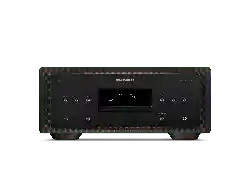
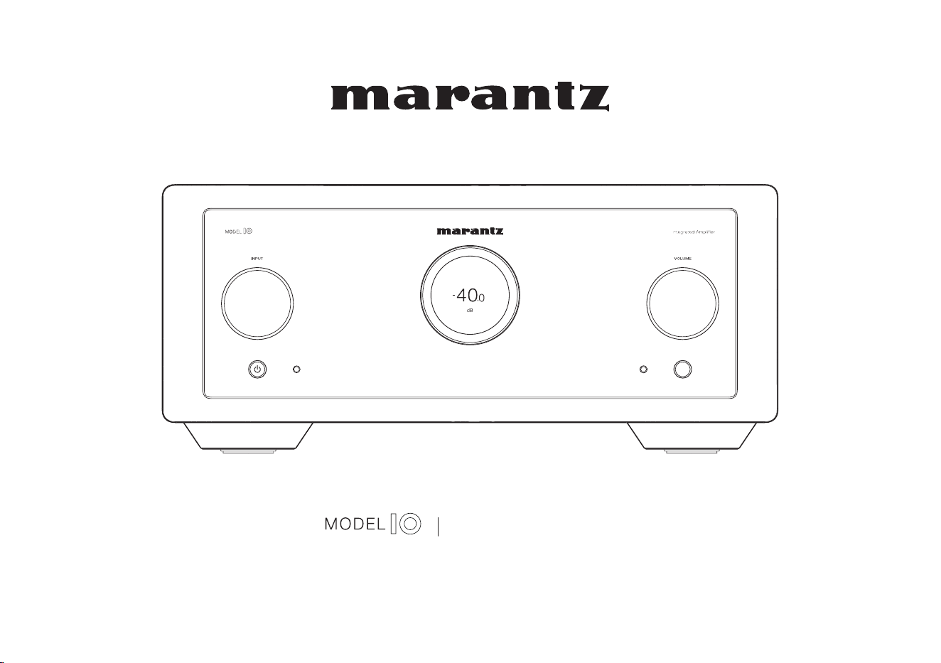
Integrated Amplifier
Owner’s Manual
1
Accessories
4
Inserting the batteries
5
Operating range of the remote control unit
5
Part names and functions
6
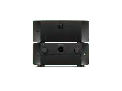
Front/Top panel
6
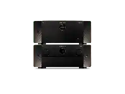
Rear panel
9
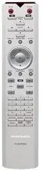
Remote control unit
11
Connections
Connecting speakers
17
Speaker A/B connection
19
Bi-wiring connection
20
Connecting a playback device
21
Connecting a recording device
23
Connecting a pre-amplifier or power amplifier
24
Connecting multiple MODEL 10 units (F.C.B.S. connection)
26
Preparation for F.C.B.S. connection
26
Stereo complete bi-amp connection
29
Connection for 5.1 Multi-channel Playback
31
Connecting an external control device
35
FLASHER IR IN jack
35
REMOTE CONTROL connectors
36
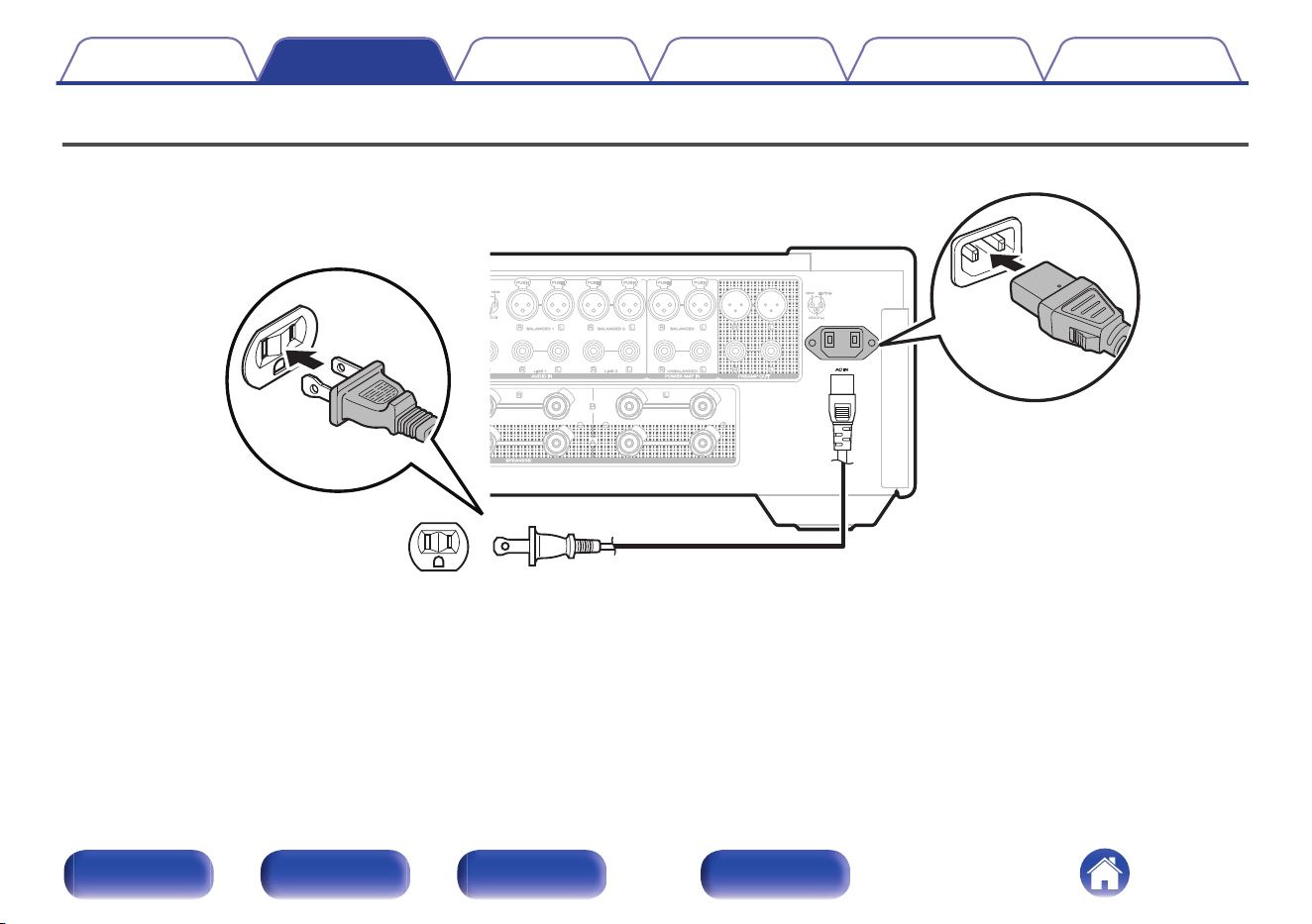
Connecting the power cord
38
Playback
Turning the power on
40
Switching the power to standby
40
Selecting the input source
41
Adjusting the volume
41
Turning off the sound temporarily (Muting)
41
Adjusting the tone and balance
42
Playback in source direct mode
44
Switching the display’s brightness
44
Turning the front panel illumination, interior illumination and
display on/off
45
Using this unit as a power amplifier
45
Recording
46
Contents Connections Playback Settings Tips Appendix
2
Front/Top
panel
Rear panel
Remote control
unit
Index
Settings
Menu map
47
Menu operation
48
Level Meter
49
Illumination
49
Volume Scale
50
Phono
50
Auto-Standby
51
Setting remote control codes
52
Setting remote control codes for the remote control
53
Setting remote control codes for the main unit
53
Disabling SACD player/streaming preamplifier operating mode
on remote control
54
Disabling SACD player operating mode
55
Disabling streaming preamplifier operating mode
55
Setting the device to be operated by the volume buttons on the
remote control
56
Setting the device to be operated by the volume buttons in SACD
player operating mode
57
Setting the device to be operated by the volume buttons in
streaming preamplifier operating mode
57
Tips
Tips
59
Troubleshooting
60
Power does not turn on / Power is turned off
61
Operations cannot be performed through the remote control unit
63
Display on this unit shows nothing
64
No sound comes out
64
Desired sound does not come out
65
Sound is interrupted or noise occurs
66
Error messages
67
Appendix
Explanation of terms
68
Specifications
69
Index
72
Contents Connections Playback Settings Tips Appendix
3
Front/Top
panel
Rear panel
Remote control
unit
Index
Thank you for purchasing this Marantz product.
To ensure proper operation, please read this owner’s manual carefully before using the product.
After reading this manual, be sure to keep it for future reference.
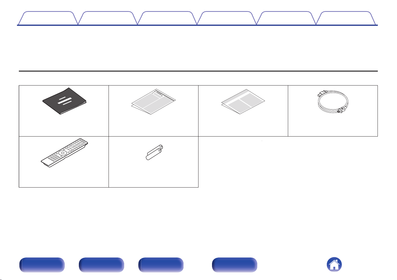
Accessories
Check that the following parts are included with the product.
Warranty
(for North America model only)
Safety InstructionsQuick Start Guide Power cord
Remote control unit
(RC004PMND)
2× R03/AAA batteries
Contents Connections Playback Settings Tips Appendix
4
Front/Top
panel
Rear panel
Remote control
unit
Index
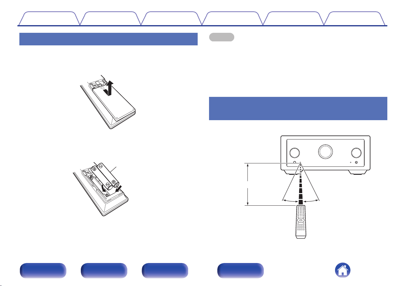
Inserting the batteries
1
Remove the rear lid in the direction of the arrow and
remove it.
2
Insert two batteries correctly into the battery
compartment as indicated.
Batteries
3
Put the rear lid back on.
NOTE
0
To prevent damage or leakage of battery fluid:
0
Do not use a new battery together with an old one.
0
Do not use two different types of batteries.
0
Remove the batteries from the remote control unit if it will not be in use for long
periods.
0
If the battery fluid should leak, carefully wipe the fluid off the inside of the battery
compartment and insert new batteries.
Operating range of the remote control
unit
Point the remote control unit at the remote sensor when operating it.
Approx. 23 ft/7 m
30° 30°
Contents
Connections Playback Settings Tips Appendix
5
Front/Top
panel
Rear panel
Remote control
unit
Index
r
we
q
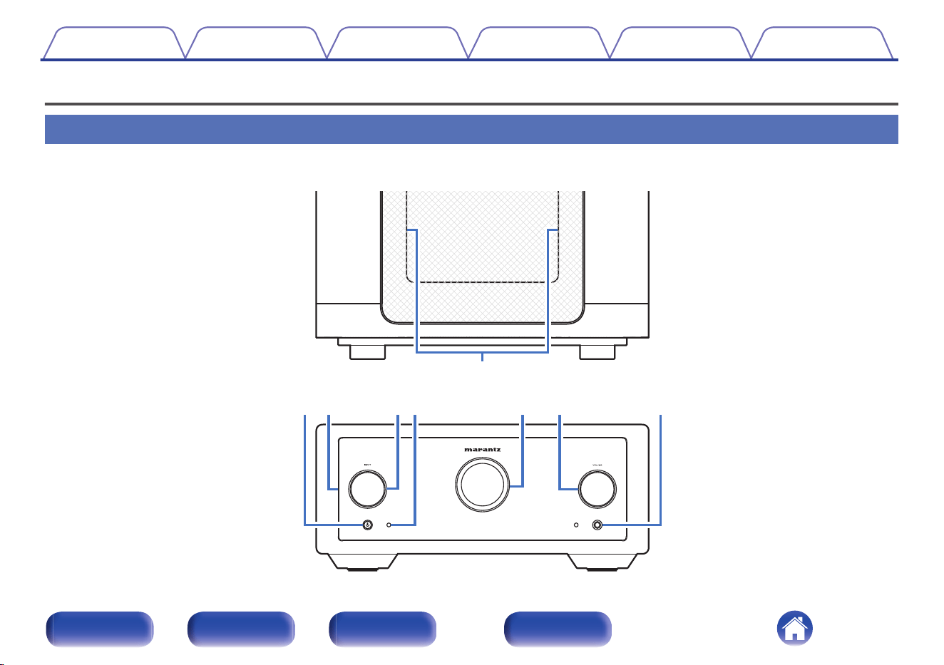
GTop panelH
GFront panelH
A
Interior illumination
Illuminates when powered on. Brightness can be changed and lighting
turned off.
0
“Turning the front panel illumination, interior illumination and display
on/off” (v p. 45)
0
“Illumination” (v p. 49)
B
Power (X) button/indicator
0
This turns the power on/off (standby). (v p. 40)
0
This is lit as follows according to the power status:
0
Power on : White
0
Standby : Off
0
When the protection circuit is activated : Orange (blinking)
C
Front panel illumination
Illuminates when powered on. Brightness can be changed and lighting
turned off.
0
“Turning the front panel illumination, interior illumination and display
on/off” (v p. 45)
0
“Illumination” (v p. 49)
D
INPUT selector knob
This selects the input source. (v p. 41)
Contents
Connections Playback Settings Tips Appendix
7
Front/Top
panel
Rear panel
Remote control
unit
Index
ty
ui
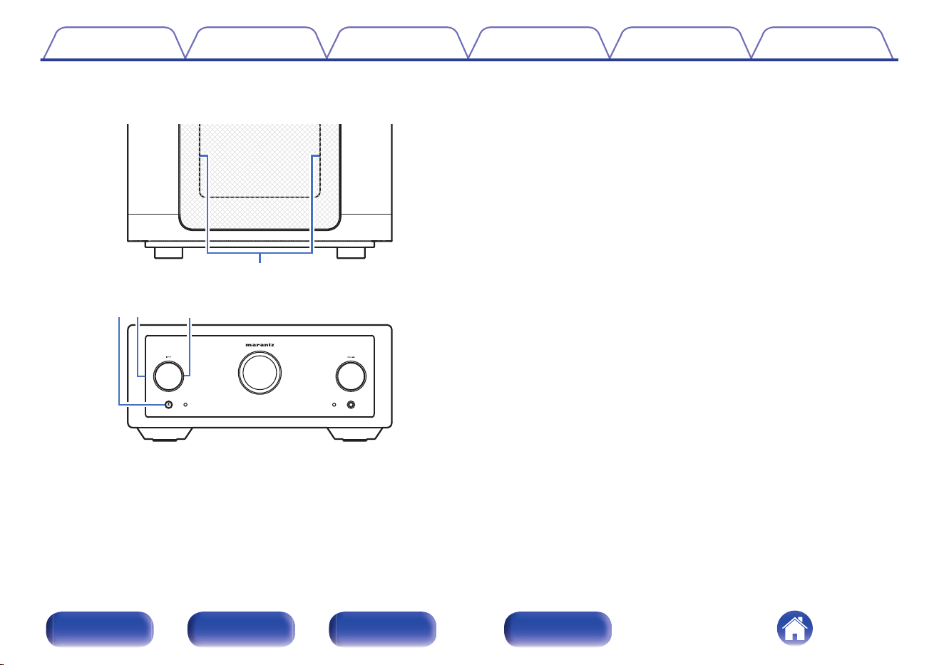
GFront panelH
E
Remote control sensor
This receives signals from the remote control unit. (v p. 5)
F
Display
This displays various pieces of information.
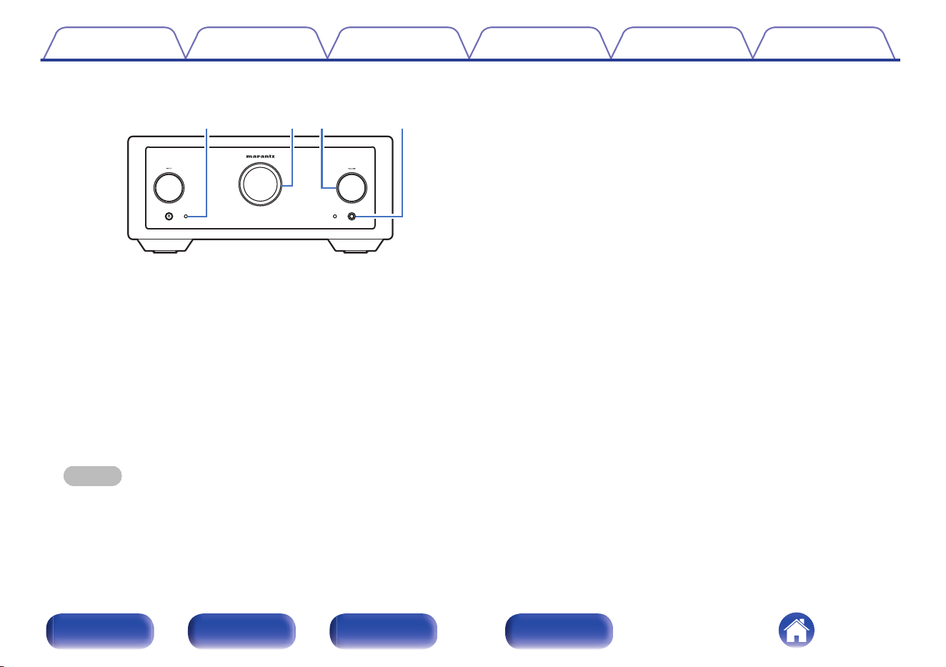
G
VOLUME knob
Adjusts the volume level. (v p. 41)
H
Headphones jack
Used to connect headphones.
When the headphones are plugged into this jack, audio will no longer
be output from the connected speakers and from the PREAMP OUT
connectors.
NOTE
0
To prevent hearing loss, do not raise the volume level excessively when using
headphones.
Contents Connections Playback Settings Tips Appendix
8
Front/Top
panel
Rear panel
Remote control
unit
Index
q erwty
Q3
u
Q2iQ0o Q1
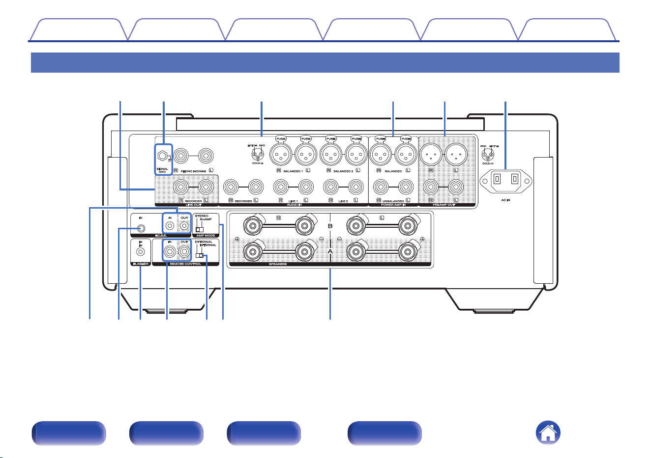
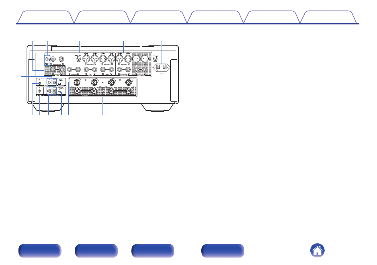
A
LINE OUT connectors (RECORDER)
Used to connect the input connector of a recorder. (v p. 23)
B
SIGNAL GND terminal
Used to connect a turntable. (v p. 21)
C
Analog audio input connectors (AUDIO IN)
Used to connect devices equipped with analog audio output
connectors.
0
“Connecting a playback device” (v p. 21)
0
“Connecting a recording device” (v p. 23)
D
Power amplifier connectors (POWER AMP IN)
Used to connect a pre-amplifier when this unit is used as a power
amplifier. (v p. 24)
E
PREAMP OUT connectors
Use this to add such equipment as a power amplifier. (v p. 24)
F
AC inlet (AC IN)
Used to connect the power cord. (v p. 38)
G
F.C.B.S. connectors
Used to connect a high quality playback system using two or more of
these units. (v p. 26)
H
F.C.B.S. ID button
Used to set the ID for F.C.B.S.. (v p. 28)
I
FLASHER IR IN jack
Used to connect a control box, etc. (v p. 35)
J
Remote control input/output connectors (REMOTE CONTROL)
Used to connect to a Marantz audio device that is compatible with the
remote control function. (v p. 36)
K
EXTERNAL/INTERNAL switch
Turn this switch to "INTERNAL", this unit receives the remote control
signal and the Marantz audio device connected to this unit using the
remote control connection operates by receiving the remote control
signal from this unit. (v p. 37)
L
AMP MODE switch
Used to switch the amplifier mode (STEREO/BI-AMP). (v p. 29)
M
Speaker terminals (SPEAKERS)
Used to connect speakers. (v p. 17)
Contents
Connections Playback Settings Tips Appendix
10
Front/Top
panel
Rear panel
Remote control
unit
Index
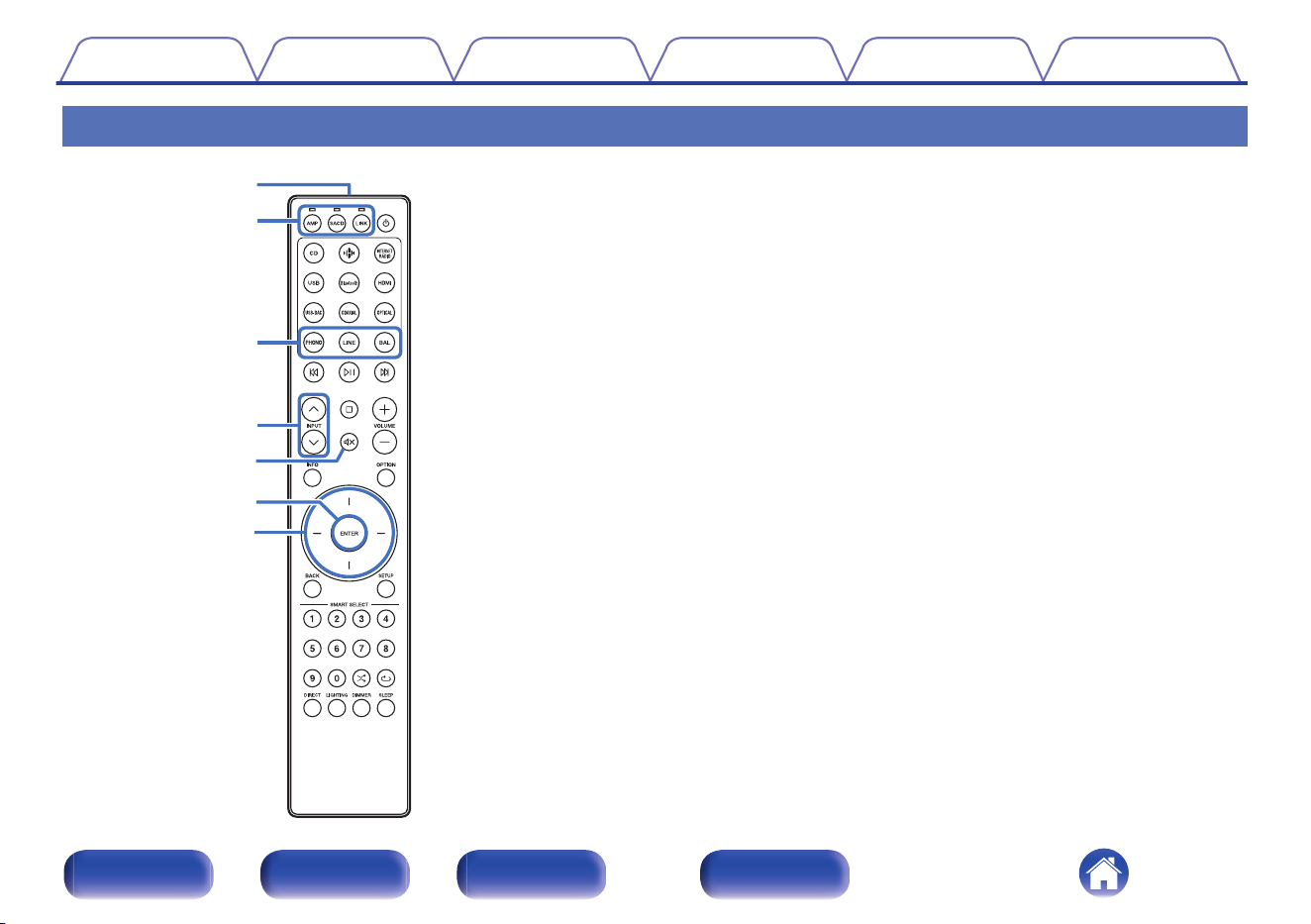
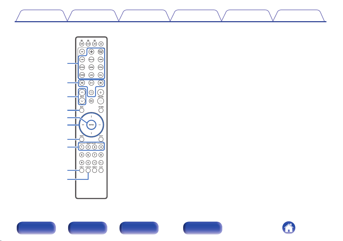
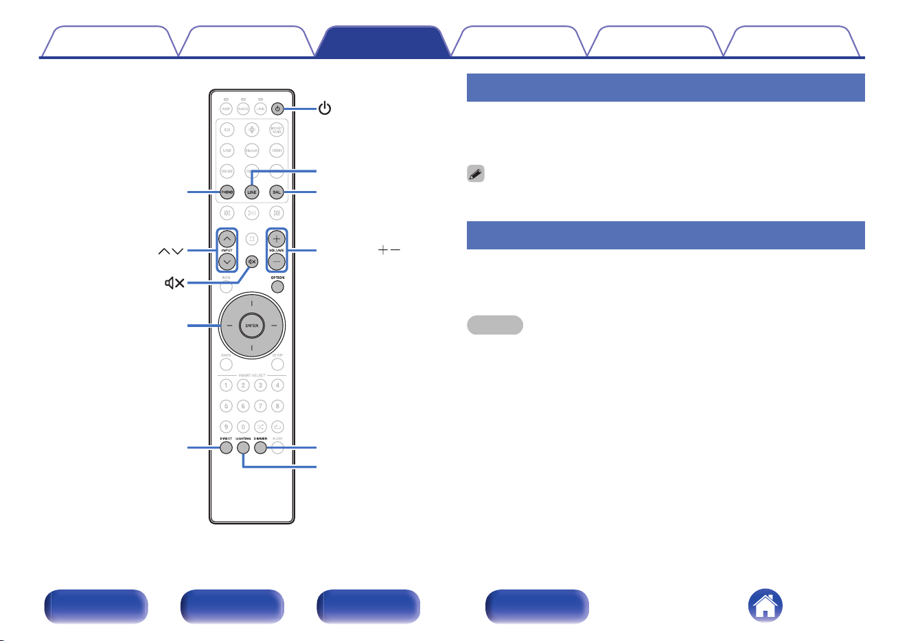
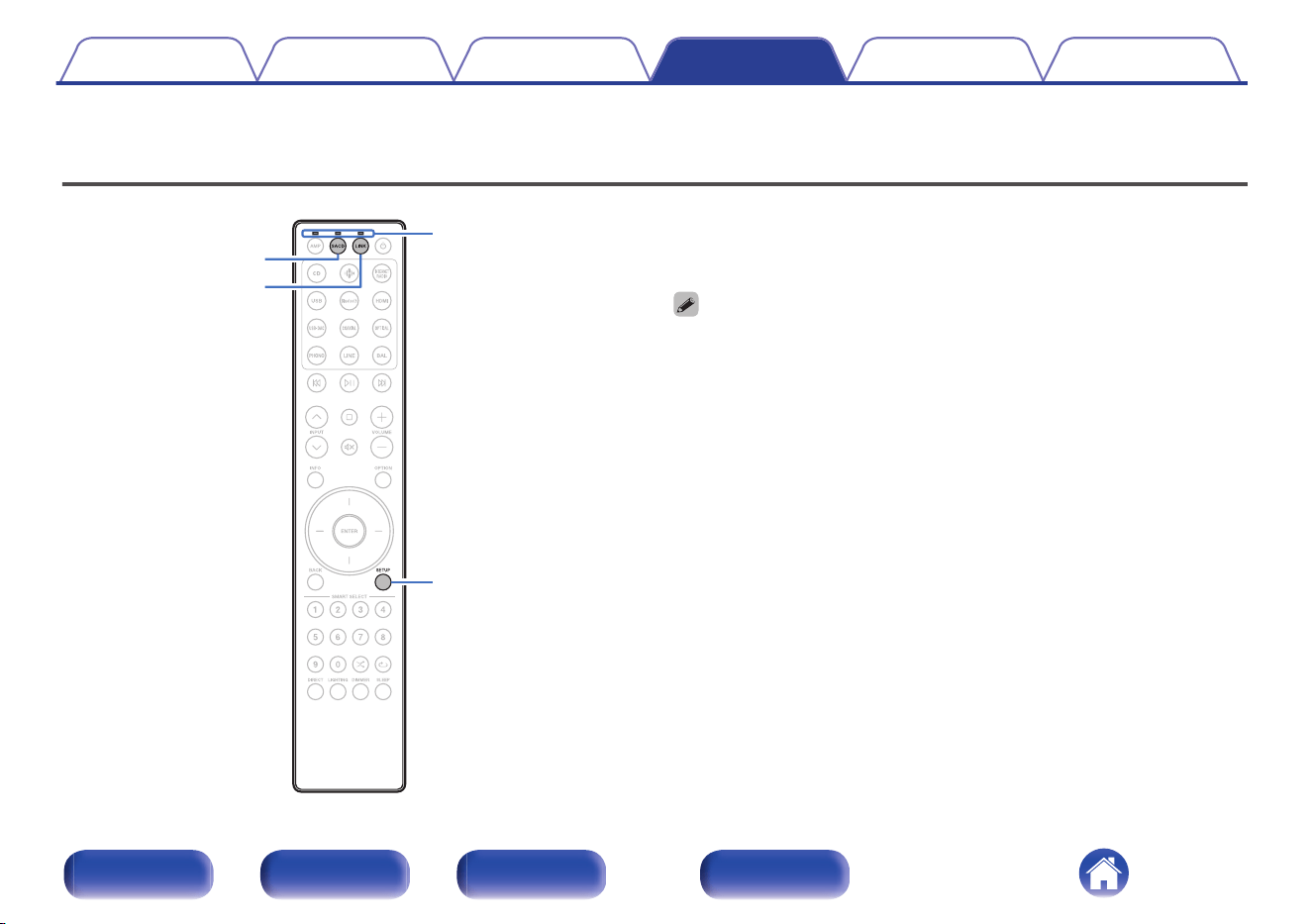
Remote control unit
w
q
r
e
t
y
u
The remote control provided with this unit can control a Marantz SACD
player and streaming preamplifier.
0
“SACD player operations” (v p. 13)
0
“Streaming preamplifier operations” (v p. 14)
o
Operating this unit
To operate this unit, press AMP button to switch the remote control
operating mode to this unit.
A
Remote control signal transmitter
This transmits signals from the remote control unit. (v p. 5)
B
Remote mode select buttons/indicators (AMP/SACD/LINK)
0
These switch the remote control operating mode (AMP/SACD/LINK).
0
The indicator will light up according to the device being operated.
C
Input source select buttons (PHONO/LINE/BAL)
This selects the input source. (v p. 41)
D
INPUT buttons (ml)
This selects the input source. (v p. 41)
E
Mute button (:)
This mutes the output audio. (v p. 41)
F
ENTER button
This determines the selection.
G
Cursor buttons
These select items.
Contents
Connections Playback Settings Tips Appendix
11
Front/Top
panel
Rear panel
Remote control
unit
Index
Q1
i
o
Q0
Q3
Q4
Q5
Q2
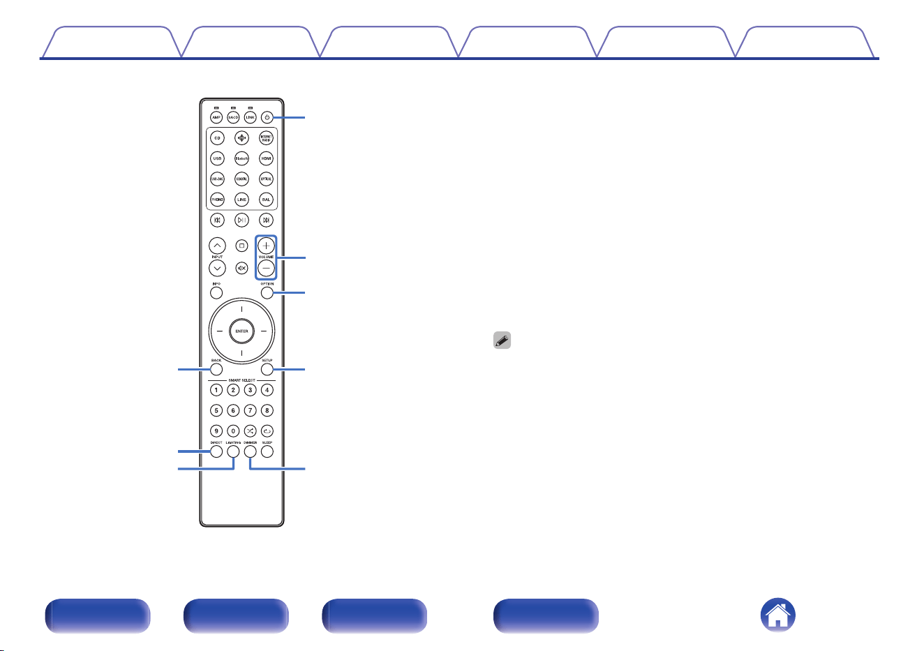
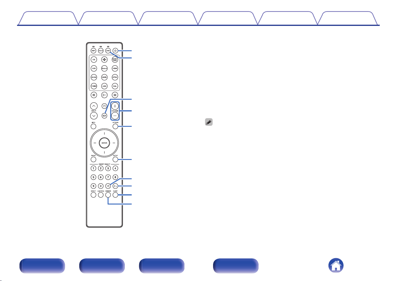
H
BACK button
Returns to the previous item.
I
DIRECT button
This turns source direct mode on/off. (v p. 44)
J
LIGHTING button
This turns the front panel illumination, interior illumination and display
on/off. (v p. 45)
K
Power (X) button
This turns the power on/off (standby). (v p. 40)
L
VOLUME buttons (no)
These adjust the volume level. (v p. 41)
M
OPTION button
This displays the option menu on the display.
0
“Adjusting the tone and balance” (v p. 42)
0
An option menu is not displayed when the input sources are “Power Amp
Balanced” and “Power Amp Unbalanced”.
N
SETUP button
The setting menu is displayed on the display. (v p. 48)
O
DIMMER button
Adjust the display brightness of this unit. (v p. 44)
Contents
Connections Playback Settings Tips Appendix
12
Front/Top
panel
Rear panel
Remote control
unit
Index
q
w
t
i
u
o
r
e
y
Q11
Q2
Q3
Q5
Q4
Q6Q0
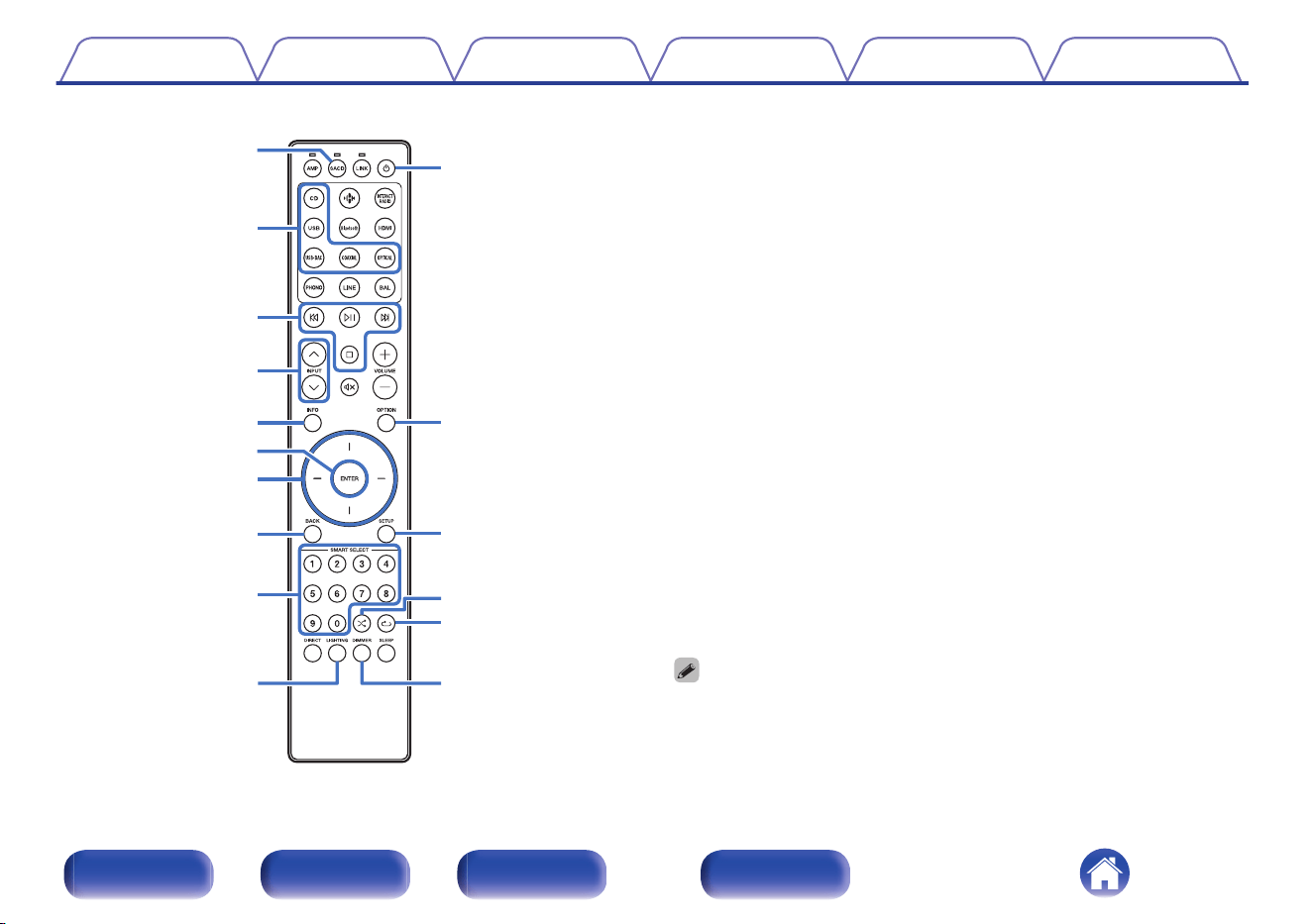
o
SACD player operations
A Marantz SACD player can be operated.
To operate SACD player, press SACD button to switch the remote
control to the SACD player operation mode.
A
Remote mode select button (SACD)
B
Input source select buttons
C
System buttons
D
INPUT buttons (ml)
E
Information button (INFO)
F
ENTER button
G
Cursor buttons
H
BACK button
I
Number buttons (0 – 9)
J
LIGHTING button
K
Power (X) button
L
OPTION button
M
SETUP button
N
Random button (s)
O
Repeat button (r)
P
DIMMER button
0
The remote control may not operate some products.
Contents Connections Playback Settings Tips Appendix
13
Front/Top
panel
Rear panel
Remote control
unit
Index
q
r
u
y
i
o
Q0
e
w
t
o
Streaming preamplifier operations
A Marantz streaming preamplifier can be operated.
To operate streaming preamplifier, press LINK button to switch the
remote control to the streaming preamplifier operation mode.
A
Input source select buttons
B
System buttons
C
INPUT buttons (ml)
D
Information button (INFO)
E
ENTER button
F
Cursor buttons
G
BACK button
H
SMART SELECT 1 - 4 buttons
I
DIRECT button
J
LIGHTING button
Contents Connections Playback Settings Tips Appendix
14
Front/Top
panel
Rear panel
Remote control
unit
Index
Q1
Q2
Q3
Q4
Q5
Q6
Q8
Q9
Q7
W0
K
Power (X) button
L
Remote mode select button (LINK)
M
Mute button (:)
N
VOLUME buttons (no)
O
OPTION button
P
SETUP button
Q
Random button (s)
R
Repeat button (r)
S
SLEEP button
T
DIMMER button
0
The remote control may not operate some products.
Contents Connections Playback Settings Tips Appendix
15
Front/Top
panel
Rear panel
Remote control
unit
Index
o
Contents
Connecting speakers 17
Connecting a playback device 21
Connecting a recording device 23
Connecting a pre-amplifier or power amplifier 24
Connecting multiple MODEL 10 units (F.C.B.S. connection) 26
Connecting an external control device 35
Connecting the power cord 38
NOTE
0
Do not plug in the power cord until all connections have been completed.
0
Do not bundle power cords together with connection cables. Doing so can result in
humming or noise.
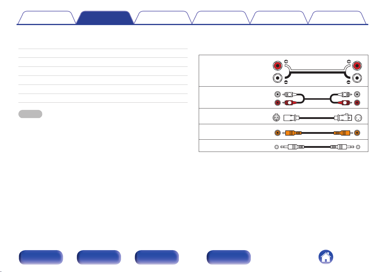
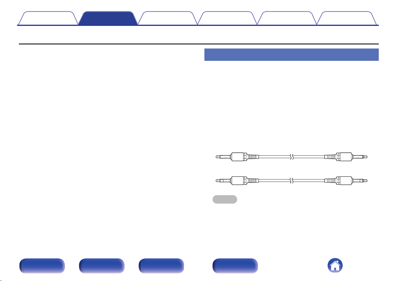
o
Cables used for connections
Provide necessary cables according to the devices you want to
connect.
Speaker cable
Audio cable
R
L
R
L
Balance cable
Remote connector cable
Monaural mini-plug cable
Contents Connections Playback Settings Tips Appendix
16
Front/Top
panel
Rear panel
Remote control
unit
Index

Connecting speakers
NOTE
0
Disconnect this unit’s power plug from the power outlet before connecting the
speakers.
0
Connect so that the speaker cable core wires do not protrude from the speaker
terminal. The protection circuit may be activated if the core wires touch the rear
panel or if the + and - sides touch each other. (“Protection circuit” (v p. 68))
0
Never touch the speaker terminals while the power cord is connected. Doing so
could result in electric shock.
0
Use speakers with impedances within the ranges shown below to suit how they
are used.
Speaker terminals
used on this unit
No. of connected
speakers
Speaker
Impedance
SPEAKERS A
(Standard
connection)
2 (one set) 4 – 16 Ω/ohms
SPEAKERS B
2 (one set) 4 – 16 Ω/ohms
SPEAKERS A and
SPEAKERS B
4 (two sets) 8 – 16 Ω/ohms
SPEAKERS A and
SPEAKERS B
(Bi-wiring
connection)
2 (one set) 4 – 16 Ω/ohms
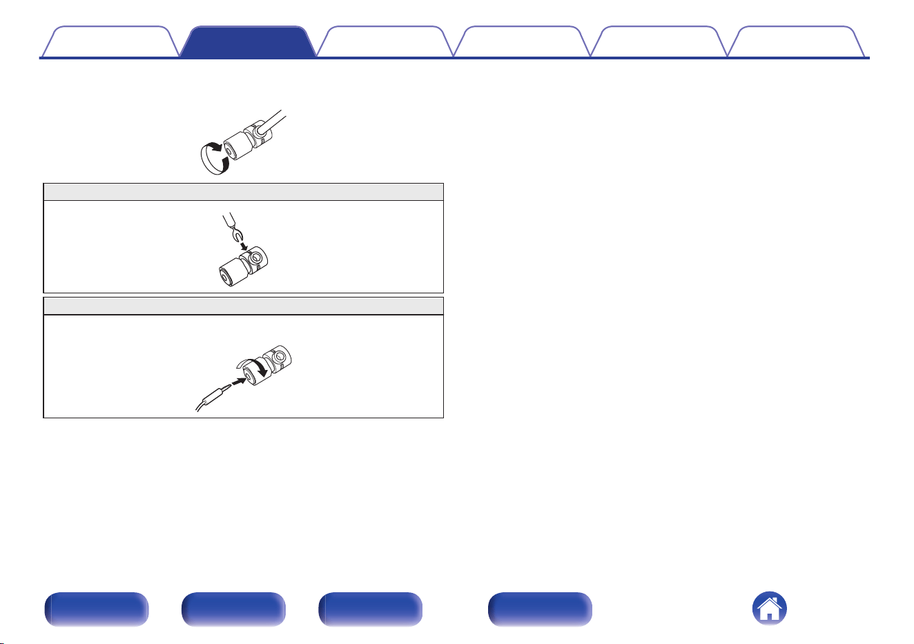
o
Connecting the speaker cables
Carefully check the left (L) and right (R) channels and + (red) and - (white)
polarities on the speakers being connected to this unit, and be sure to
connect the channels and polarities correctly.
1
Peel off about 3/8 inch (10 mm) of sheathing from the
tip of the speaker cable, then either twist the core wire
tightly or terminate it.
2
Turn the speaker terminal counterclockwise to loosen it.
3
Insert the speaker cable’s core wire to the hilt into the
speaker terminal.
Contents Connections Playback Settings Tips Appendix
17
Front/Top
panel
Rear panel
Remote control
unit
Index
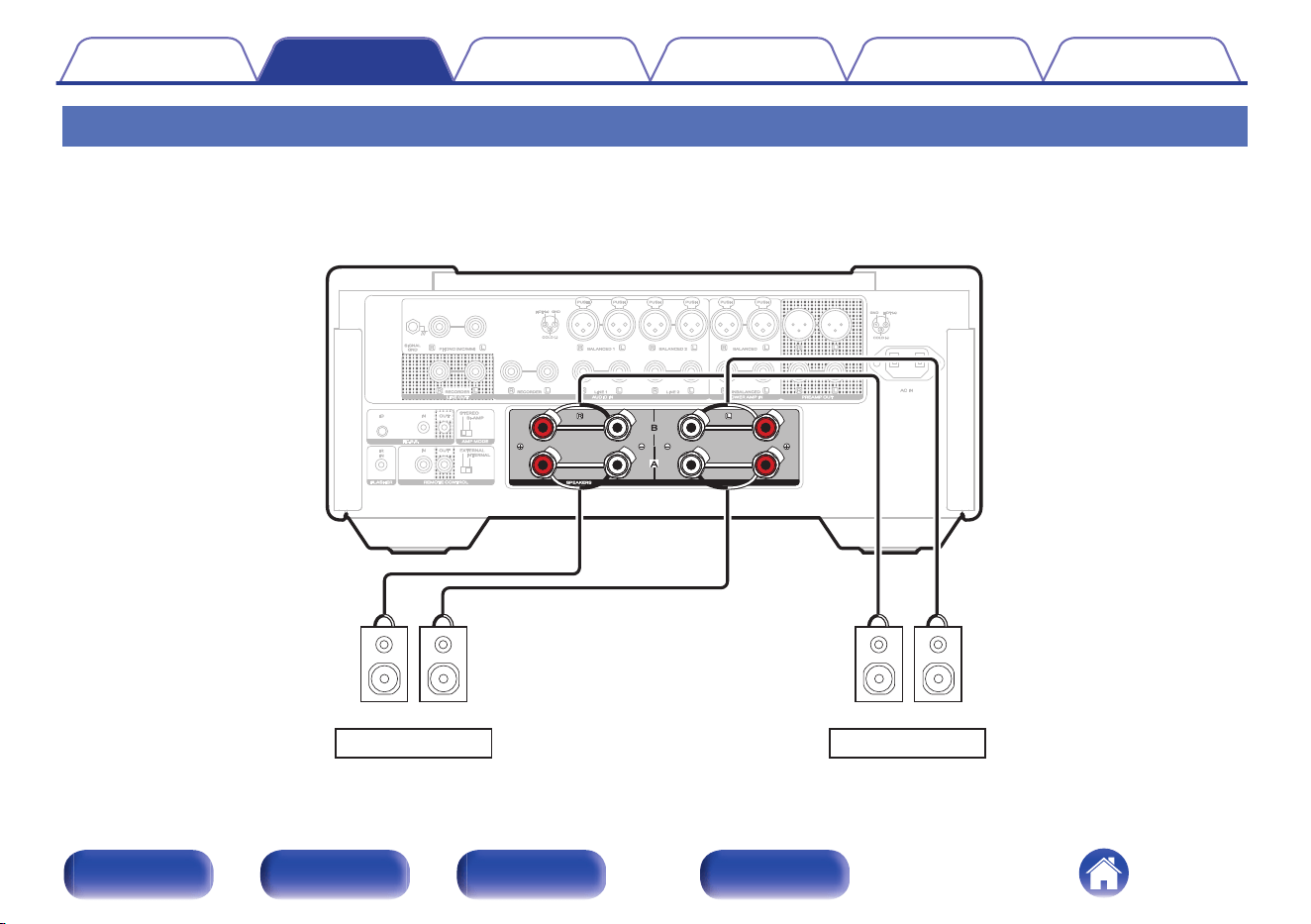
Speaker A/B connection
This unit is equipped with two sets of speaker terminals (SPEAKER A and SPEAKER B). One set of speakers can be connected to each set of terminals,
and a total of two sets of speakers can be connected.
The same signal is output from the SPEAKERS A and SPEAKERS B terminals.
When only one set of speakers is to be connected, use either the SPEAKERS A or SPEAKERS B terminals.
wqwq wqwq
SPEAKERS A
SPEAKERS B
(R) (L)
(R) (L)
Contents
Connections Playback Settings Tips Appendix
19
Front/Top
panel
Rear panel
Remote control
unit
Index
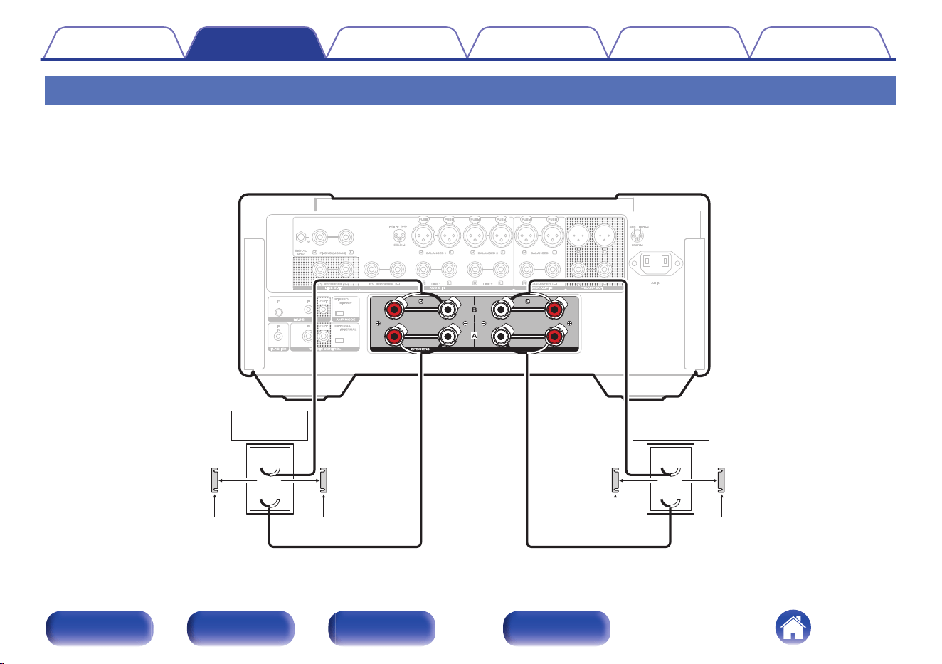
Bi-wiring connection
This connection limits the effects of signal interference between the high range speakers (tweeters) and low range speakers (woofers), allowing you to
enjoy high quality playback.
When bi-wiring with bi-wireable speakers, connect the mid and high range terminals to SPEAKERS B (or SPEAKERS A), the low range terminals to
SPEAKERS A (or SPEAKERS B).
wq
wq
HIGH
LOW
wq
wq
HIGH
LOW
Speaker
(R)
Speaker
(L)
Remove shorting bar
Remove shorting bar Remove shorting bar
Remove shorting bar
Contents Connections Playback Settings Tips Appendix
20
Front/Top
panel
Rear panel
Remote control
unit
Index
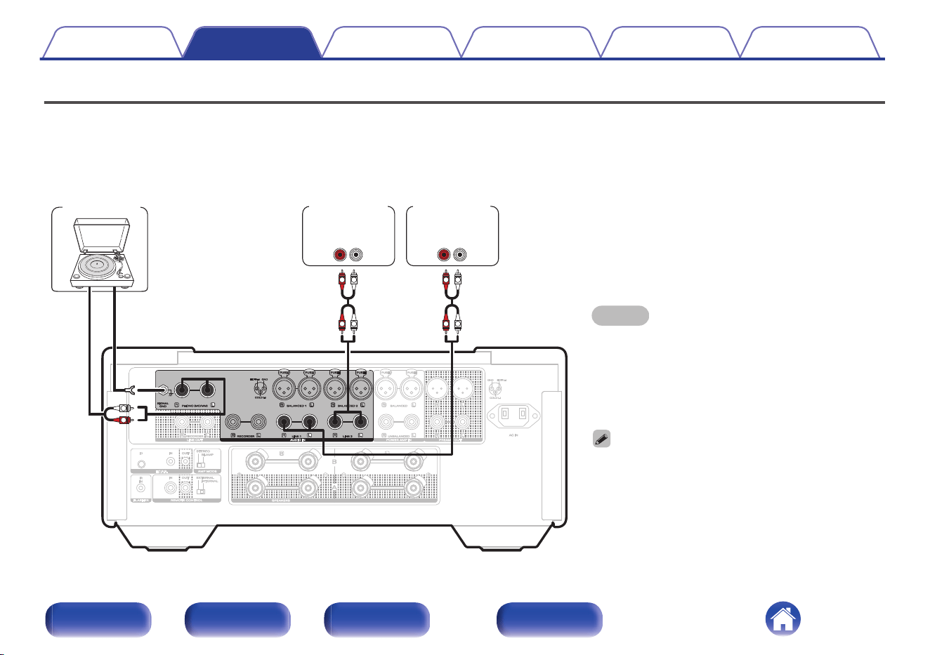
Connecting a playback device
You can connect turntables, network audio players and CD players to this unit. Set the phono equalizer of this unit in the “Phono” section of the setting
menu according to the type of turntable cartridge to be connected. (v p. 50)
If you set this unit’s input source to “Phono” and you accidentally increase the volume without having a turntable connected, you may hear a hum noise
from the speakers.
NOTE
0
The earth terminal (SIGNAL GND) of this unit is not for
safety grounding purposes. If this terminal is connected
when there is a lot of noise, the noise can be reduced.
Note that depending on the turntable, connecting the
ground line may have the reverse effect of increasing
noise. In this case, it is not necessary to connect the
ground line.
0
The PHONO input terminals are equipped with a short-
circuiting pin plug. Remove this plug to connect a record
player. Store the removed short-circuiting pin plug in a
safe place so as not to lose it.
GND
AUDIO
OUT
L
R
AUDIO
OUT
LR
AUDIO
OUT
LR
L
L
R
R
L
L
R
R
Turntable
Network audio
player
CD player
Contents Connections Playback Settings Tips Appendix
21
Front/Top
panel
Rear panel
Remote control
unit
Index
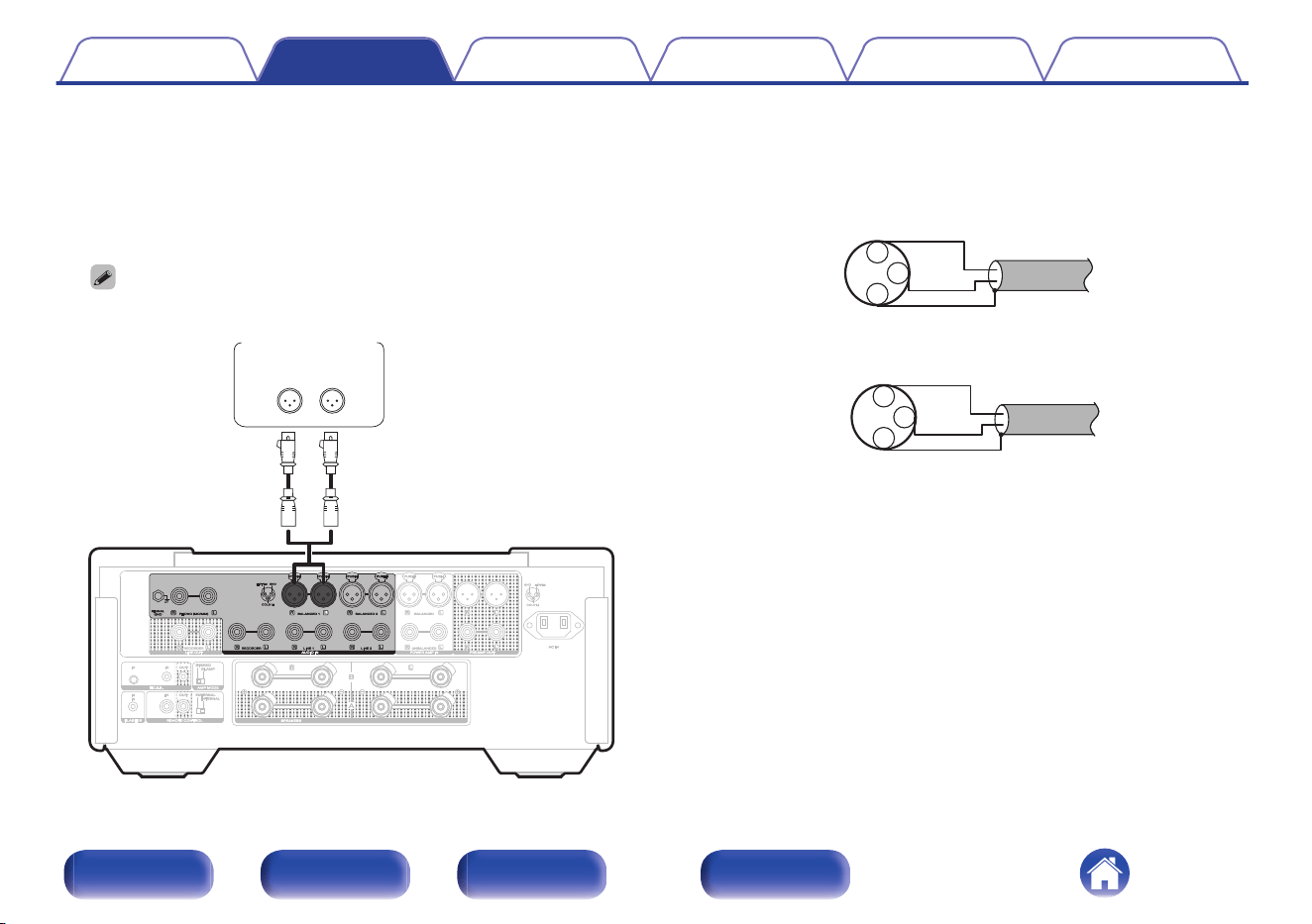
o
About balanced connectors
This unit has both unbalanced and balanced connectors. The
balanced connectors have three pins, making it possible to transmit
audio signals as a balanced signal, reducing the effect of external
noise. They also have a removable lock mechanism, which reduces
shaking in the connector area, making the connection highly reliable.
0
The balanced connection is an all-stage balanced configuration.
AUDIO OUT
LR
CD player etc.
o
Phases of the balanced connectors
The XLR connector is internally wired in either of the following two
systems. This unit employs the European system.
0
European system (B PIN=HOT/ C PIN=COLD)
1
2
3 COLD
HOT
GND
0
USA system (B PIN=COLD / C PIN=HOT)
1
2
3 HOT
COLD
GND
If a product that employs the USA system is connected with this unit
via a balanced cable, the output signal may be phase-inverted. To
correct the inversion, connect the one side XLR connector reversing
the B PIN and C PIN.
Contents
Connections Playback Settings Tips Appendix
22
Front/Top
panel
Rear panel
Remote control
unit
Index
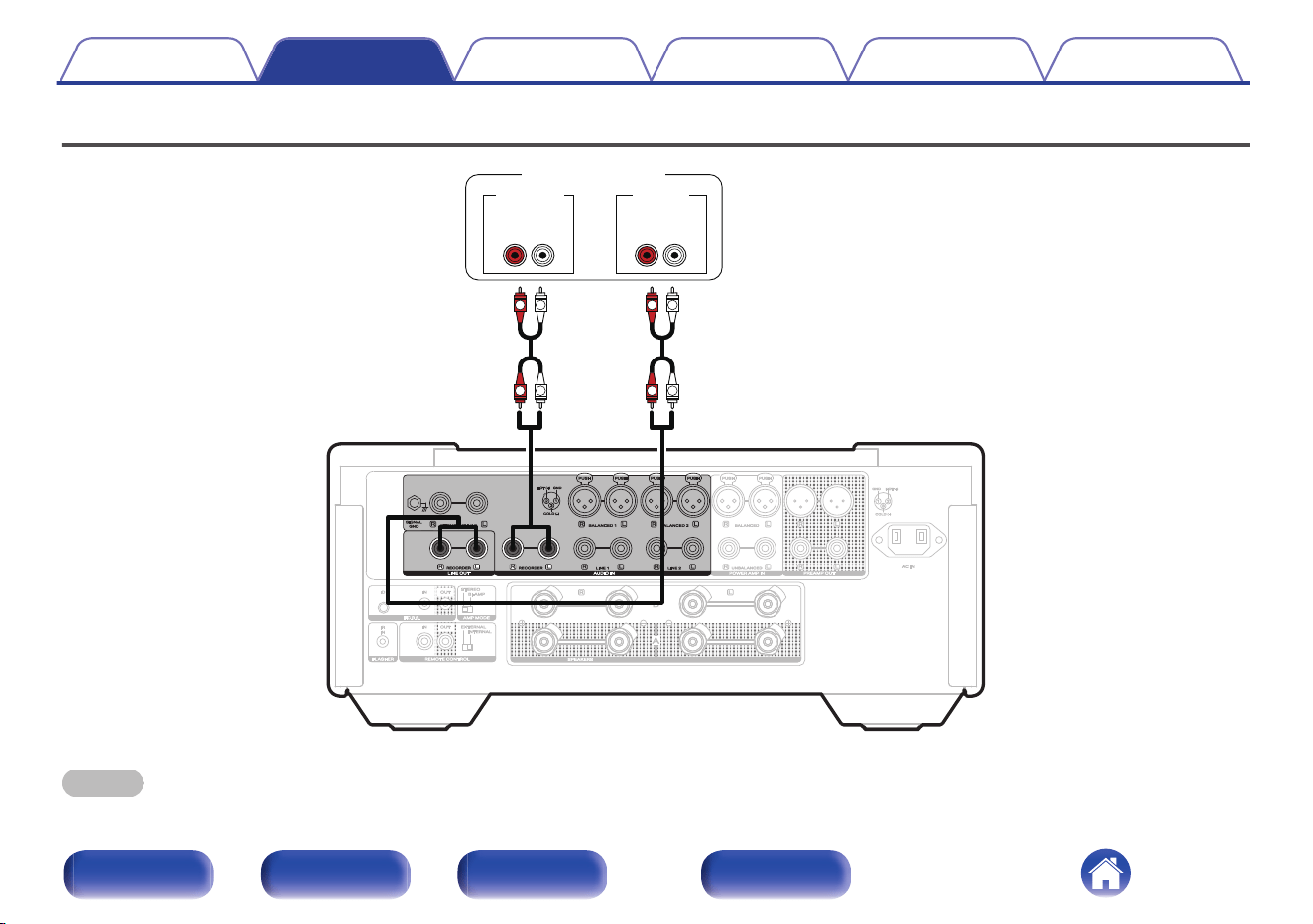
Connecting a recording device
LR
L
L
R
R
L
L
R
R
LR
AUDIO INAUDIO OUT
Recording device
NOTE
0
Never insert the short-circuiting pin plug into the recording output connectors (LINE OUT RECORDER). Doing so could result in damage.
Contents Connections Playback Settings Tips Appendix
23
Front/Top
panel
Rear panel
Remote control
unit
Index
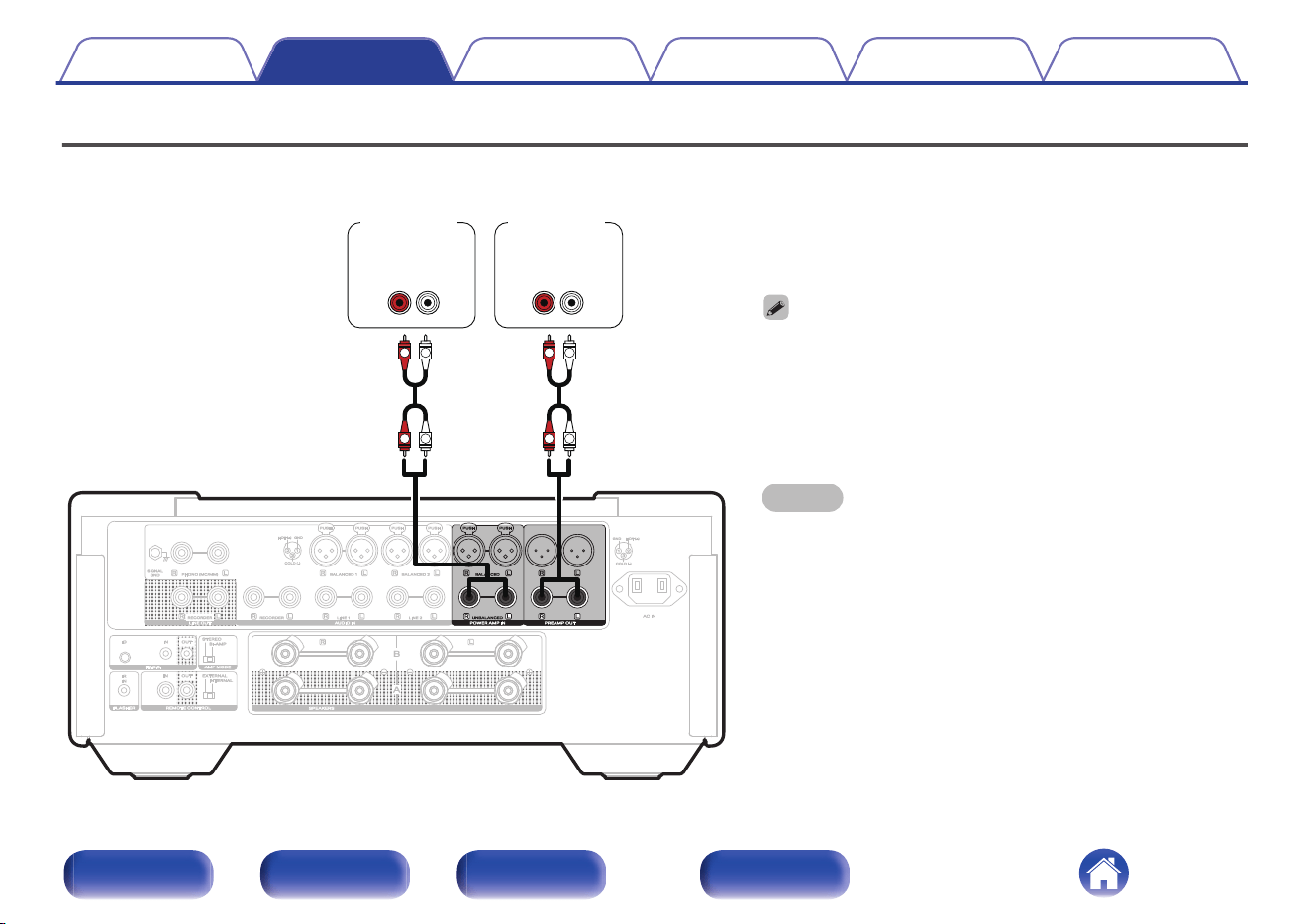
Connecting a pre-amplifier or power amplifier
Connect a power amplifier to the unit to use it as a pre-amplifier, or connect a pre-amplifier to the unit to use it as a power amplifier.
0
When connecting a pre-amplifier and using this unit as a power
amplifier, switch the input source to “Power Amp Balanced” or
“Power Amp Unbalanced”. (v p. 45)
0
The POWER AMP IN (UNBALANCED) connectors are equipped with
a short-circuiting pin plug. Remove this plug to connect a pre-
amplifier. Store the removed short-circuiting pin plug in a safe place
so as not to lose it.
NOTE
0
Never insert the short-circuiting pin plug into the PREAMP OUT
connectors. Doing so could result in damage.
LR
L
L
R
R
L
L
R
R
LR
AUDIO
OUT
AUDIO
IN
Power
amplifier
Pre-
amplifier
Contents Connections Playback Settings Tips Appendix
24
Front/Top
panel
Rear panel
Remote control
unit
Index
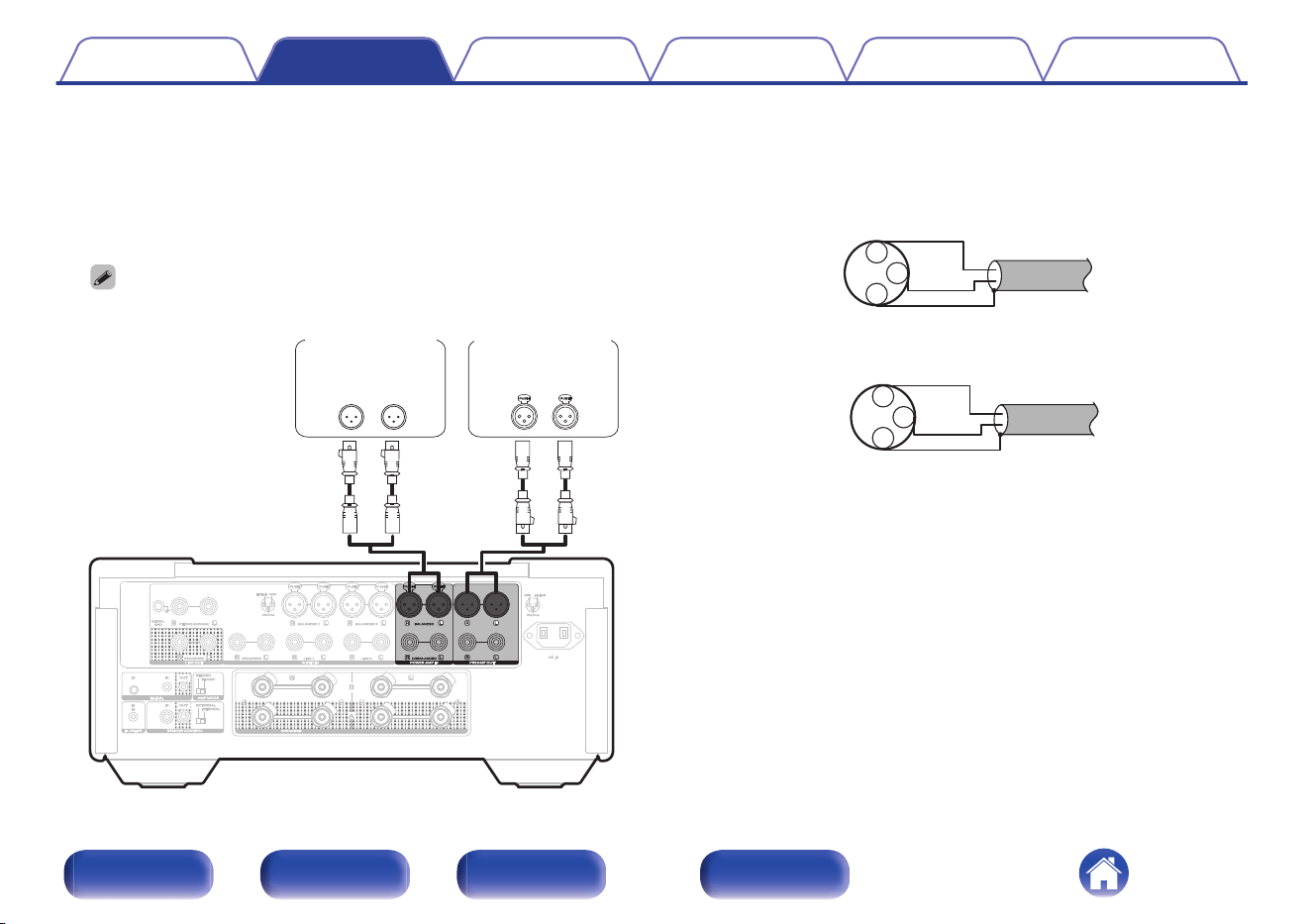
o
About balanced connectors
This unit has both unbalanced and balanced connectors. The
balanced connectors have three pins, making it possible to transmit
audio signals as a balanced signal, reducing the effect of external
noise. They also have a removable lock mechanism, which reduces
shaking in the connector area, making the connection highly reliable.
0
The balanced connection is an all-stage balanced configuration.
LR LR
Pre-amplifier
Power amplifier
AUDIO
OUT
AUDIO
IN
o
Phases of the balanced connectors
The XLR connector is internally wired in either of the following two
systems. This unit employs the European system.
0
European system (B PIN=HOT/ C PIN=COLD)
1
2
3 COLD
HOT
GND
0
USA system (B PIN=COLD / C PIN=HOT)
1
2
3 HOT
COLD
GND
If a product that employs the USA system is connected with this unit
via a balanced cable, the output signal may be phase-inverted. To
correct the inversion, connect the one side XLR connector reversing
the B PIN and C PIN.
Contents
Connections Playback Settings Tips Appendix
25
Front/Top
panel
Rear panel
Remote control
unit
Index
Connecting multiple MODEL 10 units (F.C.B.S. connection)
The Marantz F.C.B.S. (Floating Control Bus System) is the high quality
sound system for link control between multiple MODEL 10 units (up to 4
units). Each unit is controlled via its ID registered beforehand. The IDs
need to be set to an operating unit (Leader) and a subordinate unit
(Member 1 - 3) receiving the command from the leader. For member units,
register Member 1 - 3 in the order of command reception from the leader.
IDs can be set for units connected by F.C.B.S. to perform linked
operations such as switching the input source, adjusting the volume,
muting, adjusting the volume balance, adjusting the sound quality and
trimming the display brightness. Furthermore, F.C.B.S. connection of
multiple MODEL 10 units has the feature that switches this unit’s output
from stereo to monaural so that the unit can works as a monaural output
amplifier. Follow the respective instructions to make the necessary
settings.
Preparation for F.C.B.S. connection
o
Making the F.C.B.S. connection
To use multiple MODEL 10 units, make this connection in addition to
audio connection. For details on each connection feature, refer to the
respective instructions.
0
“Stereo complete bi-amp connection” (v p. 29)
0
“Connection for 5.1 Multi-channel Playback” (v p. 31)
Prepare the correct number of portable audio connection cables for the
number of units to be connected. Either of the following types of
connection cables are adequate.
0
Φ3.5 Monaural mini plug O N Φ3.5 monaural mini plug connecting
cable
0
Φ3.5 Stereo mini plug O N Φ3.5 stereo mini plug connecting cable
NOTE
0
Do not use connecting cables that contain resistance.
Contents Connections Playback Settings Tips Appendix
26
Front/Top
panel
Rear panel
Remote control
unit
Index
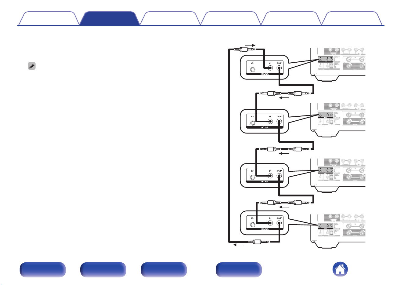
o
Connection example
In this example, the unit with ID set to “Leader” controls the units with
the IDs set to “Member 1”, “Member 2”, or “Member 3”.
0
The MODEL 10 F.C.B.S. function is only valid between the same MODEL 10
models.
0
If you want to power on multiple amplifiers connected to the F.C.B.S., please
turn on the power in the order of “Leader” - “Member 1” - “Member 2” -
“Member 3”. When turning off the power, turn them off in the reverse order.
Signal flow
Leader
Member 1
Member 2
Member 3
Contents
Connections Playback Settings Tips Appendix
27
Front/Top
panel
Rear panel
Remote control
unit
Index
o
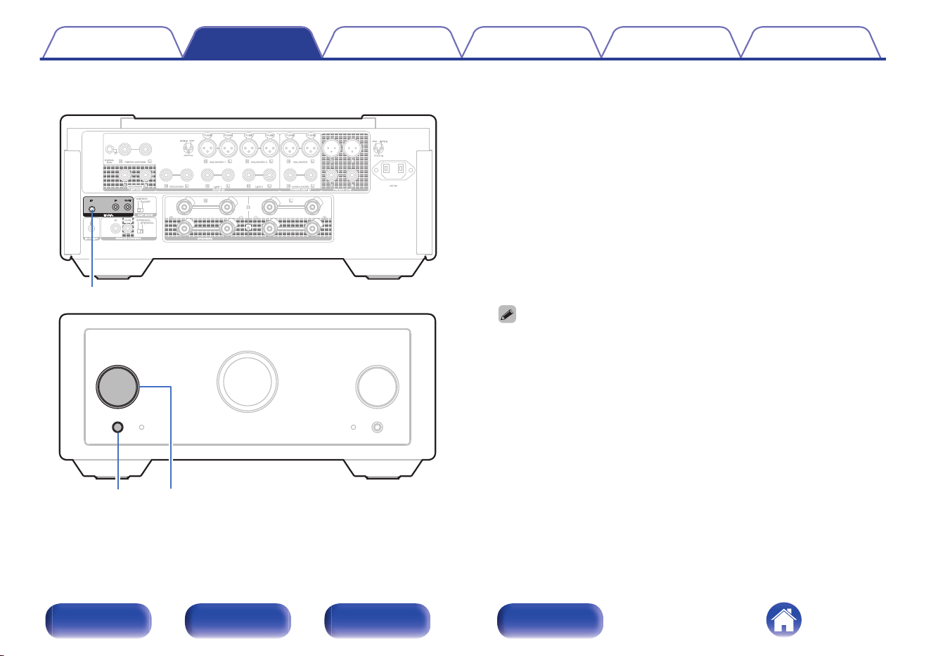
How to set ID for F.C.B.S.
F.C.B.S. ID
INPUT
X
1
While holding F.C.B.S. ID on the rear panel, press X.
2
Turn the INPUT knob on the main unit to select an ID.
0
The IDs need to be set to an operating unit (Leader) and a
subordinate unit (Member 1 - 3) receiving the command from the
leader.
3
Press F.C.B.S. ID on the rear panel to confirm the
selected ID.
After showing the ID on the display for about 3 seconds, the unit will
automatically restart.
0
If set to “Member 1”, “Member 2” or “Member 3”, the ID set on the
normal screen is displayed.
0
If using this unit by itself as a stereo amplifier, set the ID to “Off”. (Default
setting is “Off”.)
0
If the ID is set to other than “Off”, this unit cannot be used for standalone
operation.
Contents
Connections Playback Settings Tips Appendix
28
Front/Top
panel
Rear panel
Remote control
unit
Index
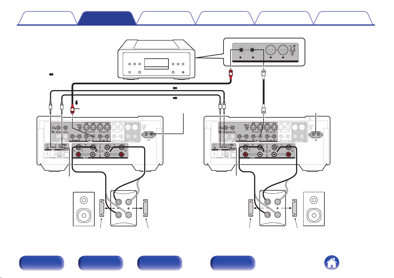
Stereo complete bi-amp connection
This mode enables the two amplifiers connected to this unit to function as
one monaural amplifier. To use this mode, two F.C.B.S. connected
MODEL 10 units are required.
To switch the mode, use the AMP MODE switch on the rear panel while
the power is off.
If this unit is set to the bi-amp mode, “BI-AMP” appears on the display.
In bi-amp mode, connect to the left channel input connector.
The right channel input is disabled.
The same signals are output from the left and right speaker terminals.
0
Be sure to turn the power off before operating the AMP MODE switch. Settings can
be configured when the power is turned on.
0
When in bi-amp mode, the R channel input connectors cannot be used.
0
When in bi-amp mode, the signals input into the L channel are output from both
channels. Therefore, the same signals are output from the L channel and R
channel in LINE OUT (RECORDER), PREAMP OUT, headphones jack.
0
Speaker systems connected using complete bi-amp connections must support bi-
amp connections. Before connecting your speakers, check in the instruction
manual that came with the speakers or contact the manufacturer to confirm
whether they support bi-amp connection.
Contents Connections Playback Settings Tips Appendix
29
Front/Top
panel
Rear panel
Remote control
unit
Index
MF / HF
LF
MF / HF
LF
BALANCED
BALANCED
LINE OUT
LINE OUT
R L R L
UNBALANCED
UNBALANCED
L
L
R
R
Super Audio CD player, etc.
: Signal flow
Set to “BI-AMP” Set to “BI-AMP”
Set MODEL 10 for
R channel to “Member 1”
To power outletTo power outlet
Remove shorting bar
Remove shorting bar
Remove shorting barRemove shorting bar
R channel
speaker
L channel
speaker
When in bi-amp mode,
connect to the L channel
input connector.
Set MODEL 10 for
L channel to “Leader”
Contents Connections Playback Settings Tips Appendix
30
Front/Top
panel
Rear panel
Remote control
unit
Index
Connection for 5.1 Multi-channel Playback
Three MODEL 10 units can be connected by F.C.B.S. and used through linked operation. For details on F.C.B.S. connection, see “Connection
example” (v p. 27).
Connect the outputs of players that have 5.1 channel analog outputs to each of the three units.
If using an active subwoofer, see the instruction manual that came with the subwoofer for further instructions.
Set the IDs for the three amplifiers as explained in How to set ID for F.C.B.S. (v p. 28)
0
When you operate the unit with the ID set to “Leader”, the units set to “Member 1” and “Member 2” are linked.
Contents Connections Playback Settings Tips Appendix
31
Front/Top
panel
Rear panel
Remote control
unit
Index
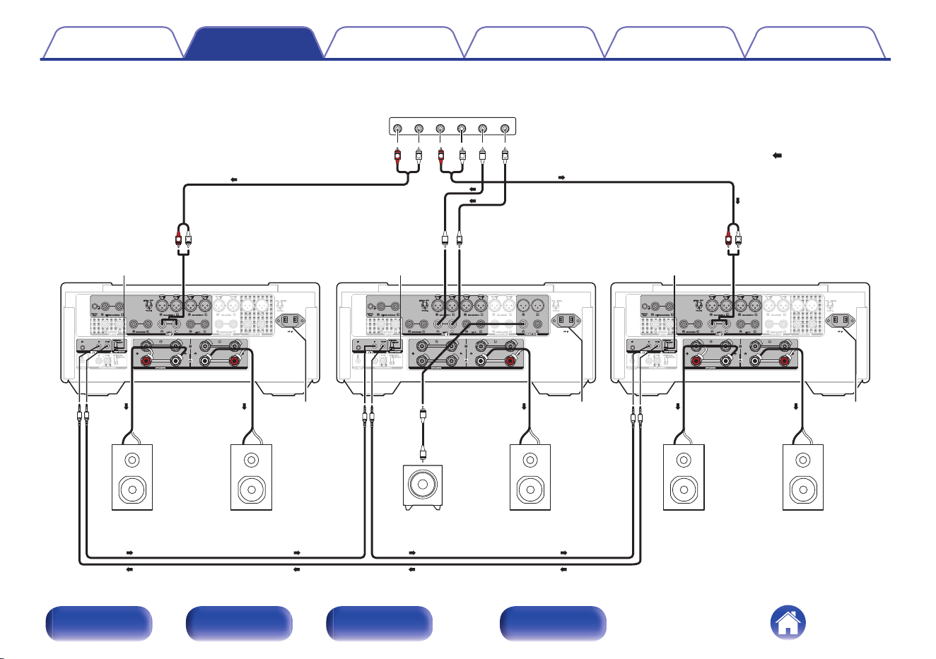
FRONT R FRONT L SURROUND R
MULTI CHANNEL AUDIO OUT
SURROUND L SUB-WOOFER CENTER
L
L
R
L
R
L
R
L L
R
: Signal flow
To power
outlet
To power
outlet
To power
outlet
Rear speaker
(Left Surround)
Rear speaker
(Right Surround)
Center speaker
Front speaker
(Left)
Front speaker
(Right)
SACD multi-channel player, etc.
Set to “STEREO” Set to “STEREO”
Set to “STEREO”
For front L/R speakers
Set MODEL 10 to
“Leader”
For center speaker
Set MODEL 10 to
“Member 1”
For surround speakers
Set MODEL 10 to
“Member 2”
Subwoofer
Contents Connections Playback Settings Tips Appendix
32
Front/Top
panel
Rear panel
Remote control
unit
Index
o
Speaker Positioning for Super Audio Multi-channel Sound
In order to enjoy Super Audio CD multi-channel sound with the best possible acoustics, it is recommended to position speakers as specified in ITU-R
BS.775-1 of the International Telecommunication Union (ITU). Super Audio CD multichannel discs are recorded and mixed so as to achieve the
optimum effect with a speaker system laid out as specified in ITU-R BS.775-1.
0
With Super Audio CD multi-channel discs, the music signals are basically recorded using 5 channels (3 - 6 channels sometimes), but in some
cases, LFE (for subwoofer) is recorded as a sixth channel.
0
Each disc indicates how many channels have been recorded on it.
0
The basic layout is 3 speakers in the front and 2 in the back since multi-channel discs usually have 5 channels. The 2 front, 1 center and 2 surround
(rear) speakers should be set in a circle around the listening point. If using speakers of differing sizes, adjust volume balance from the amplifier.
0
The location of the subwoofer in the figure is just for explanatory purposes. It can be located anywhere in the room. For connection and positioning
instructions, see the instruction manual that came with the subwoofer.
Contents Connections Playback Settings Tips Appendix
33
Front/Top
panel
Rear panel
Remote control
unit
Index
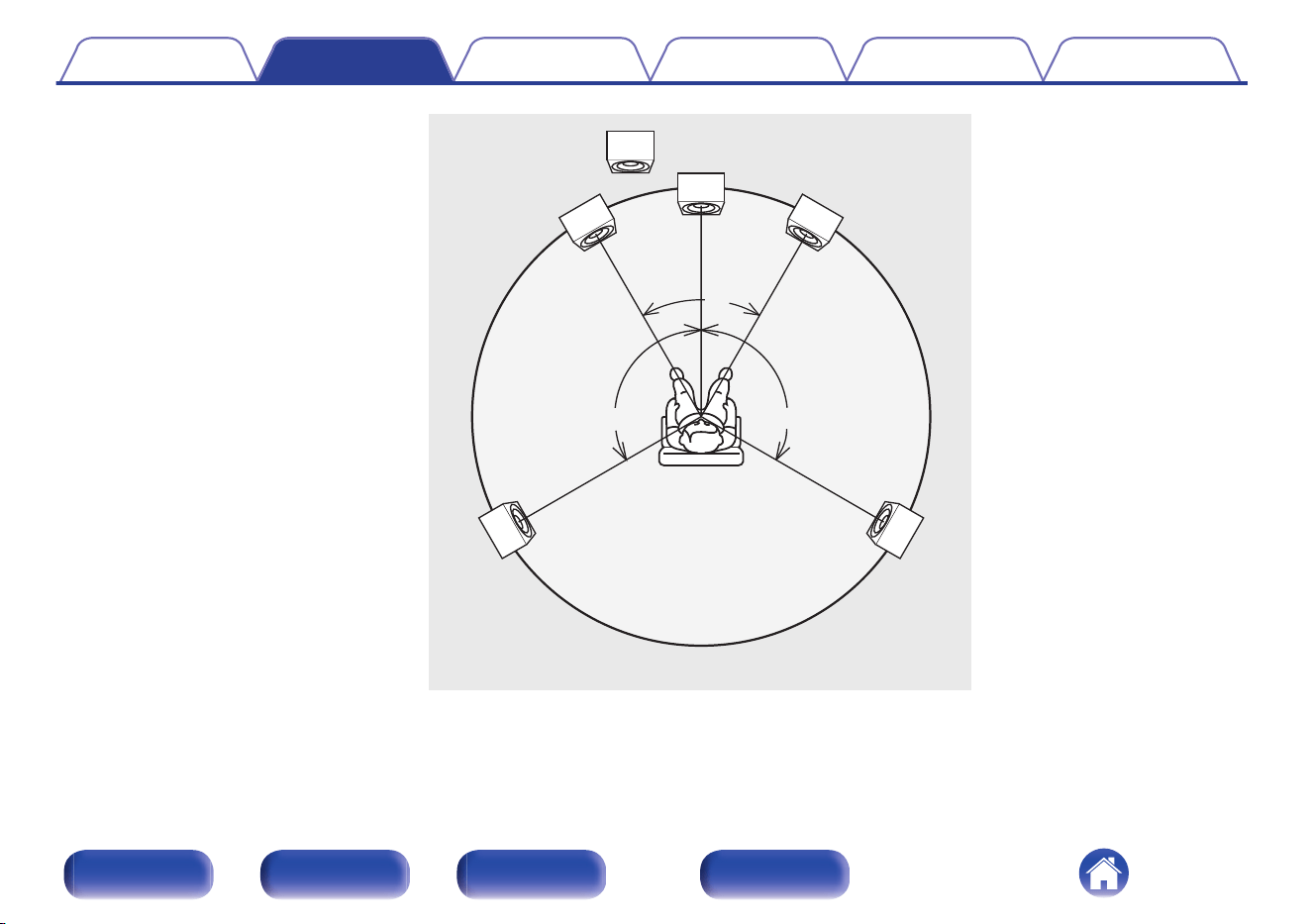
60°
Subwoofer
Center
speaker
Front speaker
(Left)
Front speaker
(Right)
Rear
speaker
(Left Surround)
Rear
speaker
(Right Surround)
approx.110°
approx.110°
Recommended
listening position
0
ITU (International Telecommunication Union)
The ITU is a special organization of the United Nations. It consists of a number of organs, one of which is the Radio Broadcasting Section.
ITU-R BS in the recommendation which consists of standards relating to broadcasting (audio) operations, one of which is the ITU-R BS.775-1 which
governs “multi-channel stereo sound systems”.
Contents
Connections Playback Settings Tips Appendix
34
Front/Top
panel
Rear panel
Remote control
unit
Index
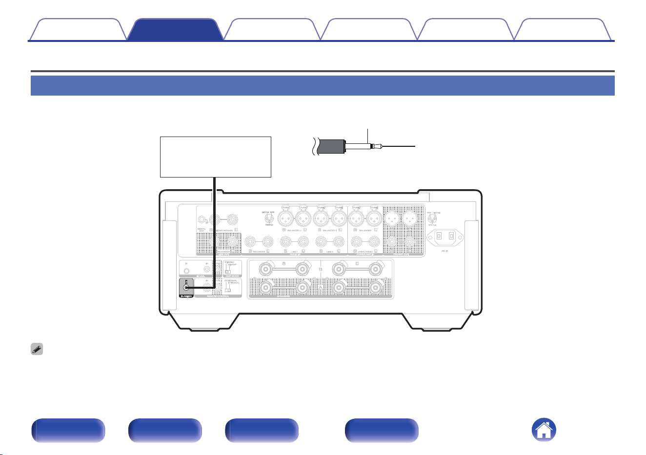
Connecting an external control device
FLASHER IR IN jack
This unit can be controlled by connecting a control box or other control device to this unit.
Control box
or
control device
GND
Signal
Monaural mini-plug cable
(not included)
0
To use the FLASHER IR IN jack, set the EXTERNAL/INTERNAL switch to “INTERNAL”.
Contents Connections Playback Settings Tips Appendix
35
Front/Top
panel
Rear panel
Remote control
unit
Index
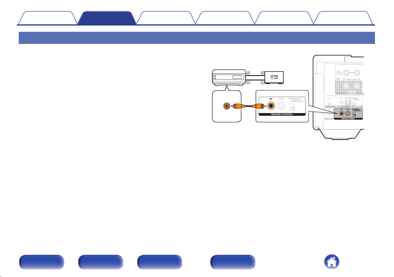
REMOTE CONTROL connectors
o
Performing operations by RC on this unit
without visual contact
You can connect an external IR receiver to the REMOTE CONTROL
connectors to perform operations on this unit with the included remote
control unit without visual contact. This might be necessary if the unit is
hidden in a cupboard or corner, so you can’t directly point with the
remote control unit to the device.
RC OUT
Infrared
retransmitter
Infrared
sensor
Contents Connections Playback Settings Tips Appendix
36
Front/Top
panel
Rear panel
Remote control
unit
Index
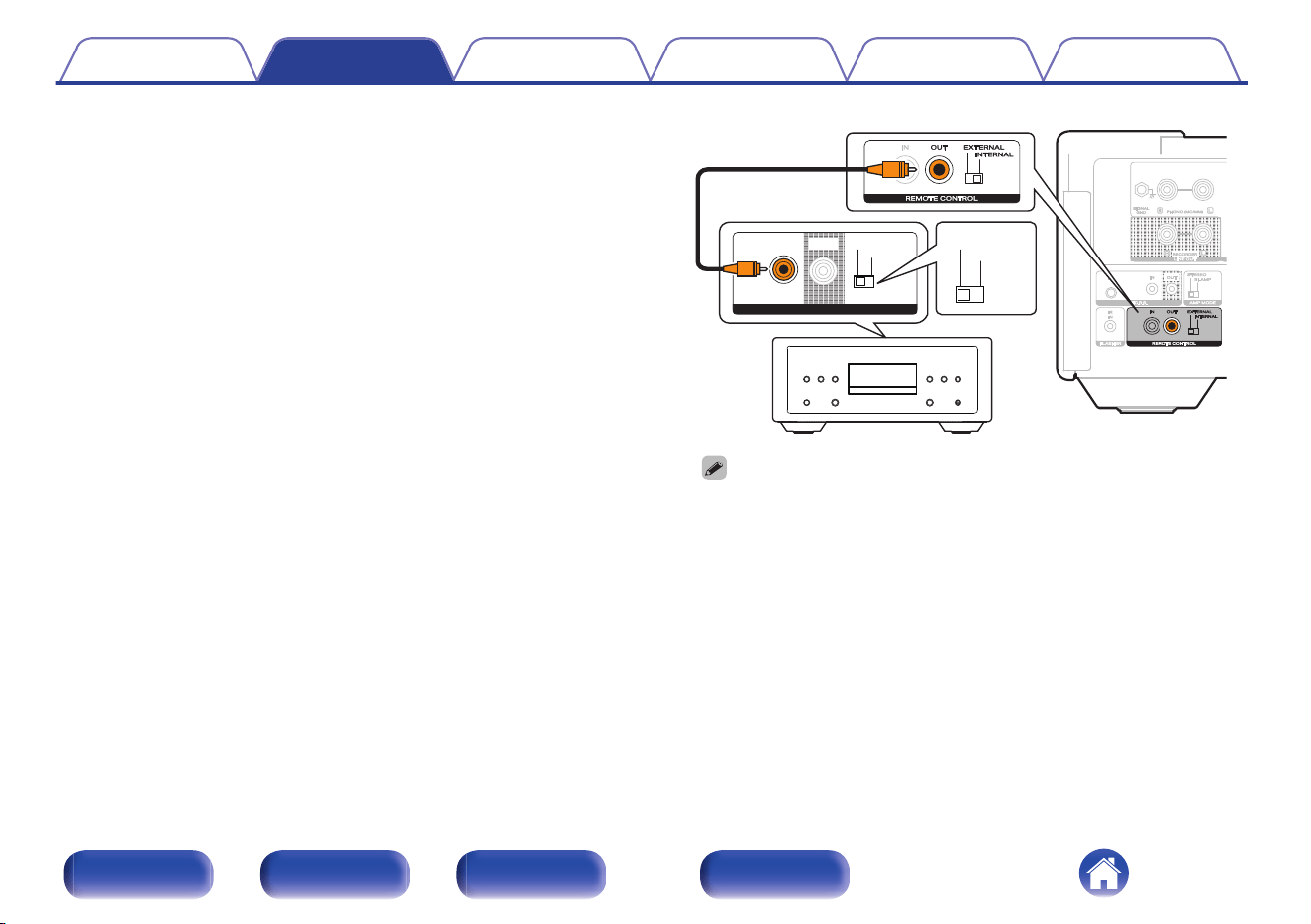
o
Remotely connecting Marantz LINK 10n and
SACD 10
If you connect the unit to the REMOTE CONTROL IN/OUT connectors
using the remote connection cable provided with the Marantz audio
unit, you can turn on the power or the standby mode of the LINK 10n
and SACD 10 in conjunction with the operation of the unit.
Set the EXTERNAL/INTERNAL switch on the rear panel of this unit
and the connected device as follows.
0
Turn this unit’s EXTERNAL/INTERNAL switch to “INTERNAL”.
0
Turn the EXTERNAL/INTERNAL switch of the connected device to
“EXTERNAL”.
ININ EXTERNALEXTERNAL
INTERNALINTERNAL
OUTOUT
REMOTE CONTROLREMOTE CONTROL
EXTERNALEXTERNAL
INTERNALINTERNAL
0
To operate the unit, point the remote control at the remote sensor of this unit.
0
To use this unit by itself without connecting a Marantz audio device, turn the
switch to “INTERNAL”.
Contents Connections Playback Settings Tips Appendix
37
Front/Top
panel
Rear panel
Remote control
unit
Index

o
Contents
Turning the power on 40
Switching the power to standby 40
Selecting the input source 41
Adjusting the volume 41
Turning off the sound temporarily (Muting) 41
Adjusting the tone and balance 42
Playback in source direct mode 44
Switching the display’s brightness 44
Turning the front panel illumination, interior illumination and display
on/off 45
Using this unit as a power amplifier 45
Recording 46
Contents Connections Playback Settings Tips Appendix
39
Front/Top
panel
Rear panel
Remote control
unit
Index
VOLUME
BAL
INPUT
DIMMER
LIGHTING
LINE
PHONO
DIRECT
ENTER
Cursor Up/Down/
Left/Right
Turning the power on
1
Press X to turn on power to the unit.
The display turns on.
0
You can also press X on the main unit to turn on power from standby mode.
Switching the power to standby
1
Press X.
The unit switches to standby mode.
NOTE
0
Power continues to be supplied to some of the circuitry even when the power is in
the standby mode. When leaving home for long periods of time or when going on
vacation, unplug the power cord from the power outlet.
Contents Connections Playback Settings Tips Appendix
40
Front/Top
panel
Rear panel
Remote control
unit
Index
Selecting the input source
1
Use input source select buttons (PHONO/LINE/BAL) to
select the input source to be played back.
The selected input source appears on the display.
0
This unit switches between Line 1 and Line 2 each time LINE is pressed.
0
This unit switches between Balanced 1 and Balanced 2 each time BAL is pressed.
0
You can also select the input source by using INPUT ml.
0
You can also select the input source by turning INPUT selector on the main unit.
Adjusting the volume
1
Use VOLUME no to adjust the volume.
The volume level appears on the display.
0
You can also adjust the volume by turning VOLUME on the main unit.
0
You can change how the volume level is displayed. (v p. 50)
Turning off the sound temporarily
(Muting)
1
Press :.
“Mute” is displayed on the display.
0
To cancel mute, either adjust the volume or press : again.
Contents Connections Playback Settings Tips Appendix
41
Front/Top
panel
Rear panel
Remote control
unit
Index
Adjusting the tone and balance
o
Adjusting the tone
1
Press OPTION.
The option menu screen is displayed.
2
Use Cursor Up/Down buttons to select “Tone”, then
press ENTER.
3
Use Cursor Up/Down buttons to select “Bass” or
“Treble”, then press ENTER.
0
If you are using an F.C.B.S. connection, a screen for selecting the
F.C.B.S. ID (“Leader”, “Member 1”, “Member 2” or “Member 3”)
will appear after step 3. Use Cursor Up/Down buttons to select
the ID of the device you want to set, then press ENTER.
4
Use Cursor Up/Down buttons to adjust the bass or
treble volume.
Bass: –10 dB – +10 dB (Default: 0 dB)
Treble: –10 dB – +10 dB (Default: 0 dB)
0
When the input source is set to “Power Amp Balanced” or “Power Amp
Unbalanced”, the tone adjustment function does not work.
0
When the source direct mode is turned on, the tone adjustment function does
not work.
Contents
Connections Playback Settings Tips Appendix
42
Front/Top
panel
Rear panel
Remote control
unit
Index
o
Adjusting the volume balance
1
Press OPTION.
The option menu screen is displayed on the display.
2
Use Cursor Up/Down buttons to select “Trim”, then
press ENTER.
3
Use Cursor Left/Right buttons to select “Left” or
“Right”.
0
If you are using an F.C.B.S. connection, a screen for selecting the
F.C.B.S. ID (“Leader”, “Member 1”, “Member 2” or “Member 3”)
will appear after step 3. Use Cursor Up/Down buttons to select
the ID of the device you want to set, then press ENTER.
4
Use Cursor Up/Down buttons to adjust the volume
balance.
Left:
-∞ (minimum), -19.0 - 0 (maximum)
(Default: 0)
Right:
-∞ (minimum), -19.0 - 0 (maximum)
(Default: 0)
0
When the input source is set to “Power Amp Balanced” or “Power Amp
Unbalanced”, the volume balance adjustment function does not work.
0
When the source direct mode is turned on, the volume balance adjustment
function does not work.
0
When the source direct mode is turned on, the “Trim” setting is set to 0
(maximum).
Contents Connections Playback Settings Tips Appendix
43
Front/Top
panel
Rear panel
Remote control
unit
Index
Playback in source direct mode
The signal does not pass through the tone adjustment circuitry, resulting in
playback of a higher sound quality.
1
Press DIRECT to turn on source direct mode.
“Source Direct” is displayed on the display.
0
When the input source is set to “Power Amp Balanced” or “Power Amp
Unbalanced”, the source direct function does not work.
Switching the display’s brightness
The display brightness can be adjusted from 100 % to Off (0 %) in steps of
5 %. Switching the display off reduces a source of noise that affects sound
quality, enabling higher sound quality playback.
1
Press DIMMER.
The dimmer menu screen is displayed on the display.
2
Use Cursor Up/Down buttons to adjust the brightness
of the display.
0
You can also adjust the brightness by pressing DIMMER.
0
If button operations are made while the display is off, information is temporarily
displayed at 100 %.
0
The display brightness is set to 100 % by default.
0
The display brightness setting is synchronized with the “Illumination” - “Display”
setting in the settings menu. (v p. 49)
0
DIMMER does not work when LIGHTING is pressed and turned off.
Contents Connections Playback Settings Tips Appendix
44
Front/Top
panel
Rear panel
Remote control
unit
Index
Turning the front panel illumination,
interior illumination and display on/off
Turn on/off the front panel illumination, interior illumination and display.
1
Press LIGHTING.
0
Each time the button is pressed, the front panel illumination,
interior illumination and display are turned on/off.
0
In the Settings menu, “Illumination” allows you to set the brightness of the front
panel illumination, interior illumination and display. (v p. 49)
0
When LIGHTING is pressed and lit, the front panel illumination, interior illumination
and display light up to the brightness set in “Illumination” in the Settings menu.
(v p. 49)
Using this unit as a power amplifier
When connecting a pre-amplifier and using this unit as a power amplifier,
switch the input source of this unit to “Power Amp Balanced” or “Power
Amp Unbalanced”.
Select “Power Amp Balanced” if the connection is balanced, or “Power
Amp Unbalanced” if the connection is unbalanced.
1
Use INPUT ml to switch the input source to “Power
Amp Balanced” or “Power Amp Unbalanced”.
“Power Amp Balanced” or “Power Amp Unbalanced” is displayed on
the display.
0
When the input source is “Power Amp Balanced” or “Power Amp Unbalanced”,
adjustment of the volume, balance and tone has no effect. Adjust these
adjustments on the pre-amplifier.
NOTE
0
When the input source is “Power Amp Balanced” or “Power Amp Unbalanced”, the
main unit outputs at maximum volume. Check the output level on the input device
before playing it and adjust the volume accordingly.
Contents Connections Playback Settings Tips Appendix
45
Front/Top
panel
Rear panel
Remote control
unit
Index
Recording
Audio signals input into this unit can be output to an external recording
device. When recording audio from a playback device connected to this
unit, audio can be recorded with the playback device still connected to this
unit.
1
Press X to turn the power on.
2
Use INPUT ml to switch to the input source from
which you want to record.
The selected input source appears on the display.
3
Recording starts.
0
For information on operations, see the owner’s manual of the
recording device.
0
When this unit is in standby mode, no audio output from LINE OUT connectors.
Contents Connections Playback Settings Tips Appendix
46
Front/Top
panel
Rear panel
Remote control
unit
Index
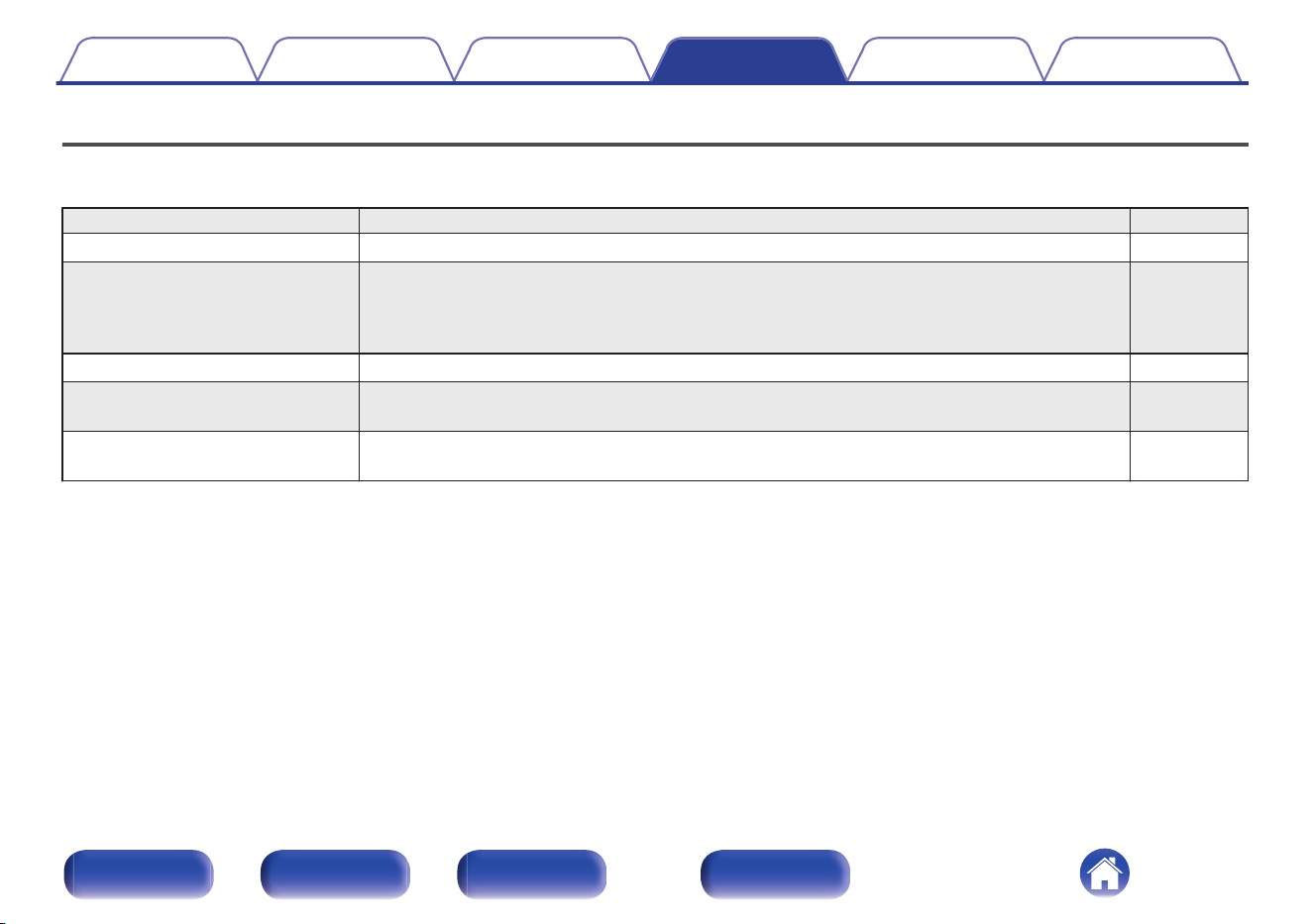
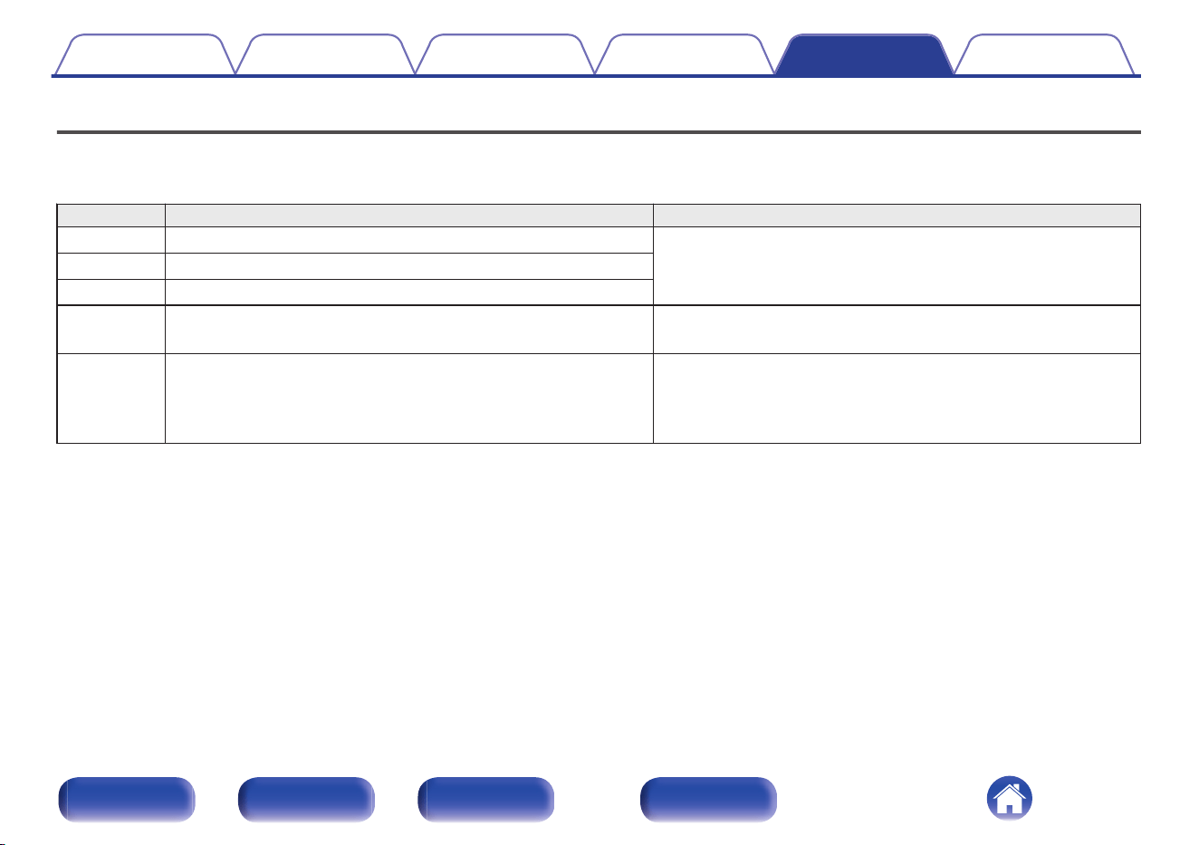
Menu map
For menu operations, see the following page.
By default, this unit has recommended settings defined. You can customize this unit based on your existing system and your preferences.
Setting items Description Page
Level Meter Sets whether to display the level meter. 49
Illumination You can adjust the brightness of the front panel illumination, interior illumination and display. You
can also link the front panel illumination and the interior illumination to the brightness of the display.
When the brightness is turned “Off”, the noise source affecting the sound quality is suppressed,
and high-quality sound playback is possible.
49
Volume Scale Set how the volume is displayed. 50
Phono Sets the phono equalizer of this unit according to the type or impedance of the turntable cartridge
to be connected.
50
Auto-Standby Sets whether to automatically switch the unit to the standby mode when there is no audio input and
no operations are performed for more than 15 minutes.
51
Contents Connections Playback Settings Tips Appendix
47
Front/Top
panel
Rear panel
Remote control
unit
Index
BACK
SETUP
ENTER
Cursor Up/Down
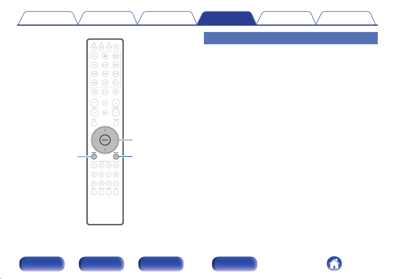
Menu operation
1
Press SETUP.
The setup menu is displayed on the display.
2
Use Cursor Up/Down buttons to select the menu to be
set or operated, then press ENTER.
3
Use Cursor Up/Down buttons to change to desired
setting.
4
Press ENTER to enter the setting.
0
To return to the previous item, press BACK.
0
Exiting the Menu, press SETUP while the setup menu is
displayed. The display returns to the normal display.
Contents Connections Playback Settings Tips Appendix
48
Front/Top
panel
Rear panel
Remote control
unit
Index
Level Meter
Sets whether to display the level meter. The level meter displays the
output level.
Off
(Default):
The level meter is not displayed.
Power Amp:
The level meter is displayed if the input
source is “Power Amp Balanced” or “Power
Amp Unbalanced”.
On:
The level meter is displayed on all input
sources.
Illumination
You can adjust the brightness of the front panel illumination, interior
illumination and display. You can also link the front panel illumination and
the interior illumination to the brightness of the display. When the
brightness is turned “Off”, the noise source affecting the sound quality is
suppressed, and high-quality sound playback is possible.
o
Display
100 – 5 (Default: 100)
Off
0
The display brightness setting is synchronized with the Dimmer menu setting.
(v p. 44)
o
Front Panel
Sync
(Default):
The brightness of the front panel
illumination is linked to the brightness of
the display.
100 – 5
Off
o
Interior
Sync
(Default):
The brightness of the interior illumination
is linked to the brightness of the display.
100 – 5
Off
Contents Connections Playback Settings Tips Appendix
49
Front/Top
panel
Rear panel
Remote control
unit
Index

Volume Scale
Set how the volume is displayed.
-99.5 dB – 0 dB
(Default):
Display volume in relative value.
0 – 100: Display volume in absolute value.
Phono
Sets the phono equalizer of this unit according to the type or impedance of
the turntable cartridge to be connected.
MM
(Default):
Set this for an MM cartridge.
MC-Low:
Use this setting for an MC cartridge of less
than 50 Ω/ohms.
MC-Mid:
Use this setting for an MC cartridge of
about 50 Ω/ohms.
MC-High:
Use this setting for an MC cartridge of 100
Ω/ohms or higher.
0
For an MC cartridge, select the input impedance closest to the impedance
recommended for the cartridge used or select a value a few times that of the
cartridge’s internal impedance.
0
If this setting change operation is performed, playback sound is output
approximately 4 seconds after the change.
Contents
Connections Playback Settings Tips Appendix
50
Front/Top
panel
Rear panel
Remote control
unit
Index
Auto-Standby
Sets whether to automatically switch the unit to the standby mode when
there is no audio input and no operations are performed for more than 15
minutes.
Off
(Default):
Disable Auto Standby mode.
On: Enable Auto Standby mode.
0
The display will show the remaining time for three minutes before the units enters
standby mode.
0
In F.C.B.S. connection, only the ID “Leader” unit activates Auto Standby mode. If
the ID “Leader” unit is operated with no audio input, set the Auto Standby mode to
off.
Contents
Connections Playback Settings Tips Appendix
51
Front/Top
panel
Rear panel
Remote control
unit
Index
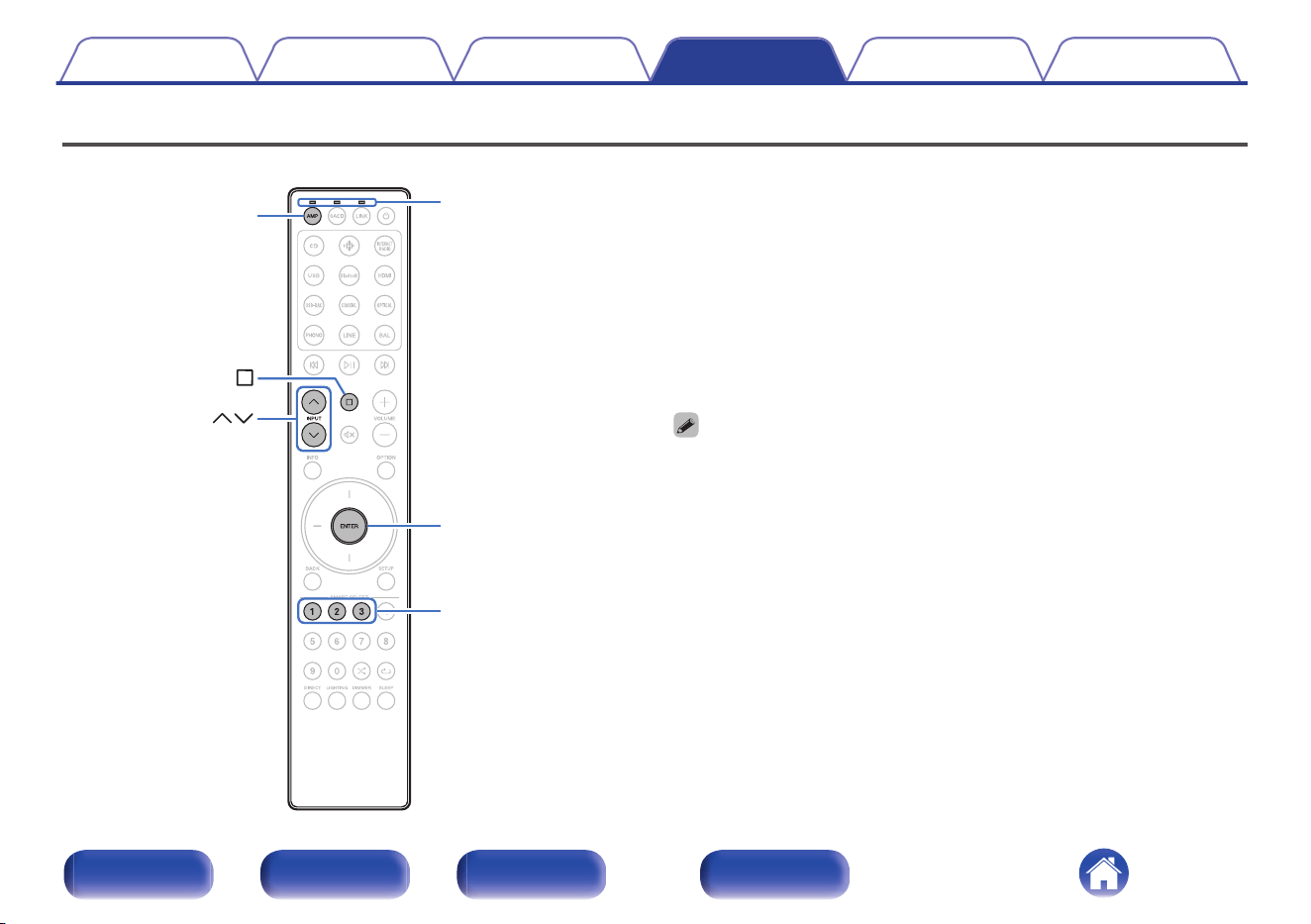
Setting remote control codes
INPUT
1 – 3
ENTER
Remote mode
select indicators
AMP
Remote control codes are set between this unit and the included remote
control. You can select one of the three types of remote control codes, and
the remote control can be used to control the unit when the same remote
control code is used. If three of these units are used in the same location,
all three units can be controlled simultaneously using one remote control
in the default settings. By setting individual remote control codes between
a unit and the remote control, the remote control can be used to control
only the unit that has the same remote control code.
Be sure to check the operation of each unit after setting the remote control
codes.
The default setting is “AMP 1”.
0
Set the remote control cord to “AMP 1” when controlling this unit from a Marantz
SACD player, streaming preampifier or other device connected using a remote
connection cable to this unit. (v p. 37)
Contents Connections Playback Settings Tips Appendix
52
Front/Top
panel
Rear panel
Remote control
unit
Index
Setting remote control codes for the
remote control
o
To set the remote control codes to AMP 1,
AMP 2 or AMP 3
1
Press AMP.
0
Set the remote control to amplifier operating mode.
2
Hold down i and one of the number 1, 2 or 3 buttons
for more than 5 seconds.
The remote mode select indicators will flash green.
0
Set the remote control code to AMP 1, AMP 2 or AMP 3
according to the selected number button.
Setting remote control codes for the
main unit
1
Point the remote control for which the remote control
code was set at the main unit, and press i and ENTER.
When setting the remote control code of the main unit is complete,
the remote control code set (AMP 1 – 3) is displayed on the display.
Contents Connections Playback Settings Tips Appendix
53
Front/Top
panel
Rear panel
Remote control
unit
Index
Disabling SACD player/streaming preamplifier operating mode on remote
control
SETUP
SACD
LINK
Remote mode
select indicators
If you do not want to use this unit in combination with SACD 10 or LINK
10n, you can disable the remote control operating mode of the device that
you are not using. By default, all remote control operating modes are
enabled.
0
When remote control operating mode is enabled, be sure to check the operation of
your device.
Contents Connections Playback Settings Tips Appendix
54
Front/Top
panel
Rear panel
Remote control
unit
Index

Disabling SACD player operating mode
1
Press and hold SACD and SETUP simultaneously until
the remote mode select indicators flash green.
0
Each time you perform Step 1, the SACD player operating mode
is toggled between enabled/disabled.
Disabling streaming preamplifier
operating mode
1
Press and hold LINK and SETUP simultaneously until
the remote mode select indicators flash green.
0
Each time you perform Step 1, the streaming preamplifier
operating mode is toggled between enabled/disabled.
Contents Connections Playback Settings Tips Appendix
55
Front/Top
panel
Rear panel
Remote control
unit
Index

Setting the device to be operated by the volume buttons on the remote
control
ENTER
1 – 2
On the included remote control, you can set the device to be operated by
the volume buttons so that you can adjust the volume of this unit when it is
either in SACD player operating mode or streaming preamplifier operating
mode. You can select either “Amplifier” or “Streaming Preamplifier” as the
device to be operated by the volume buttons on the remote control.
0
After setting the device to be operated by the volume buttons on the remote
control, be sure to check the operation of your device.
0
Switching the device to be operated affects the VOLUME no and : buttons on
the remote control.
Contents
Connections Playback Settings Tips Appendix
56
Front/Top
panel
Rear panel
Remote control
unit
Index
Setting the device to be operated by
the volume buttons in SACD player
operating mode
If you use a Marantz SACD player in combination with this unit, you can
adjust the volume of this unit without switching to amplifier operating mode
while the included remote control is set to SACD player operating mode.
By default, the device to be operated is set to “Amplifier”.
o
Set the device to be operated by the volume
buttons to this unit (amplifier)
1
Press and hold ENTER and 1 on the remote control
simultaneously for 5 seconds or more.
The AMP indicator will flash green.
o
Set the device to be operated by the volume
buttons to the streaming preamplifier
1
Press and hold ENTER and 2 on the remote control
simultaneously for 5 seconds or more.
The LINK indicator will flash green.
Setting the device to be operated by
the volume buttons in streaming
preamplifier operating mode
If you use a Marantz streaming preamplifier in combination with this unit,
you can adjust the volume of this unit without switching to amplifier
operating mode while the included remote control is set to streaming
preamplifier operating mode.
By default, the device to be operated is set to “Streaming Preamplifier”.
o
Set the device to be operated by the volume
buttons to the streaming preamplifier
1
Press and hold ENTER and 1 on the remote control
simultaneously for 5 seconds or more.
The LINK indicator will flash green.
o
Set the device to be operated by the volume
buttons to this unit (amplifier)
1
Press and hold ENTER and 2 on the remote control
simultaneously for 5 seconds or more.
The AMP indicator will flash green.
Contents Connections Playback Settings Tips Appendix
57
Front/Top
panel
Rear panel
Remote control
unit
Index
o
Contents
Tips
I want to adjust the tone myself 59
I want to turn the display off 59
I want to turn off the front panel illumination, interior illumination
and display 59
I want to use two or more of MODEL 10 units for high quality
playback 59
I want to operate a Marantz SACD player and streaming
preamplifier using the remote control of this unit 59
I want to use this unit as a power amplifier 59
I want to use this unit as a pre-amplifier 59
I want to use more than one unit in one location 59
Troubleshooting
Power does not turn on / Power is turned off 61
Operations cannot be performed through the remote control unit 63
Display on this unit shows nothing 64
No sound comes out 64
Desired sound does not come out 65
Sound is interrupted or noise occurs 66
Contents Connections Playback Settings Tips Appendix
58
Front/Top
panel
Rear panel
Remote control
unit
Index
Tips
I want to adjust the tone myself
0
Press the OPTION button to adjust “Tone” setting on the option menu. (v p. 42)
I want to turn the display off
0
Press the DIMMER button to adjust the display’s brightness on the dimmer menu. (v p. 44)
I want to turn off the front panel illumination, interior illumination and display
0
Press the LIGHTING button to turn off. (v p. 45)
I want to use two or more of MODEL 10 units for high quality playback
0
Use the stereo complete bi-amp connections. (v p. 29)
0
Use the multi-channel playback connections. (v p. 31)
I want to operate a Marantz SACD player and streaming preamplifier using the remote control of this unit
0
Marantz SACD player and streaming preamplifier can also be operated with the remote control of this unit. Also refer to the SACD player and streaming
preamplifier instruction manuals for those players. (v p. 13)
I want to use this unit as a power amplifier
0
Connect a pre-amplifier to the POWER AMP IN connectors of this unit and switch the input source to “Power Amp Balanced” or “Power Amp
Unbalanced”. (v p. 24)
I want to use this unit as a pre-amplifier
0
Connect a power amplifier to the PREAMP OUT connectors of this unit. (v p. 24)
I want to use more than one unit in one location
0
Set individual remote control codes for each combination of devices and remote control. (v p. 52)
Contents
Connections Playback Settings Tips Appendix
59
Front/Top
panel
Rear panel
Remote control
unit
Index

Troubleshooting
If a problem should arise, first check the following:
1. Are the connections correct?
2. Is the set being operated as described in the owner’s manual?
3. Are the other devices operating properly?
If this unit does not operate properly, check the corresponding symptoms in this section.
If the symptoms do not match any of those described here, consult your dealer as it could be due to a fault in this unit. In this case, disconnect the power
immediately and contact the store where you purchased this unit.
Contents Connections Playback Settings Tips Appendix
60
Front/Top
panel
Rear panel
Remote control
unit
Index
Power does not turn on / Power is turned off
Power is not turned on.
0
Check whether the power plug is correctly inserted into the power outlet. (v p. 38)
0
This unit is in standby mode. Press the X button on the main unit or the X button on the remote control. (v p. 40)
Power automatically turns off.
0
The Auto Standby mode is on. When approx. 15 minutes pass with no audio input and no operations on the unit, this unit automatically enters the
standby mode. To turn off the Auto Standby mode, set “Auto-Standby” on the setup menu to “Off”. (v p. 51)
0
When this unit and a Marantz audio device compatible with the power synchronization function are connected using a remote connection cable, the
power of this unit turns off (standby) in synchronization with the power off operation of the device connected to this unit. (v p. 36)
The power turns off and the power indicator shows one long blink and two short blinks in orange.
0
Stop playback on the playback device, and then turn the power off and on again.
0
If the problem is not solved by turning the power off and on again, this unit’s amplifier circuit has failed. Unplug the power cord and contact our customer
service center.
The power turns off and the power indicator shows one long blink and three short blinks in orange.
0
This unit’s power circuit has failed. Unplug the power cord and contact our customer service center.
Contents
Connections Playback Settings Tips Appendix
61
Front/Top
panel
Rear panel
Remote control
unit
Index
The power turns off and the power indicator shows one long blink and four short blinks in orange.
0
The protection circuit has been activated due to a rise in temperature within this unit. Turn the power off, wait about an hour until this unit cools down
sufficiently, and then turn the power on again.
0
Please re-install this unit in a place having good ventilation.
0
Stop playback on the playback device, and then turn the power off and on again.
The power turns off and the power indicator shows one long blink and five short blinks in orange.
0
Check the speaker connections. The protection circuit may have been activated because speaker cable core wires came in contact with each other or a
core wire was disconnected from the connector and came in contact with the rear panel of this unit. After unplugging the power cord, take corrective
action such as firmly re-twisting the core wire or taking care of the connector, and then reconnect the wire. (v p. 17)
0
Stop playback on the playback device, and then turn the power off and on again.
0
If the problem is not solved by turning the power off and on again, this unit’s amplifier circuit or power circuit has failed. Unplug the power cord and
contact our customer service center.
The power turns off and the power indicator shows one long blink and six short blinks in orange.
0
This unit’s power circuit has failed. Unplug the power cord and contact our customer service center.
Contents
Connections Playback Settings Tips Appendix
62
Front/Top
panel
Rear panel
Remote control
unit
Index

Operations cannot be performed through the remote control unit
Operations cannot be performed through the remote control unit.
0
Batteries are worn out. Replace with new batteries. (v p. 5)
0
Operate the remote control unit within a distance of about 23 ft/7 m from this unit and at an angle of within 30°. (v p. 5)
0
Remove any obstacle between this unit and the remote control unit.
0
Insert the batteries in the proper direction, checking the q and w marks. (v p. 5)
0
The set’s remote control sensor is exposed to strong light (direct sunlight, inverter type fluorescent bulb light, etc.). Move the set to a place in which the
remote control sensor will not be exposed to strong light.
0
When using a 3D video device, the remote control unit of this unit may not function due to effects of infrared communications between units (such as TV
and glasses for 3D viewing). In this case, adjust the direction of units with the 3D communications function and their distance to ensure they do not
affect operations from the remote control unit of this unit.
0
Press the AMP button to switch the remote control operating mode to amplifier operating mode. (v p. 11)
0
Remote control amplifier operating mode is disabled. Press and hold the AMP and SETUP buttons simultaneously for 3 seconds or more to enable amp
operating mode.
0
The device to be operated by the VOLUME no and : buttons is a Marantz streaming preamplifier. If the remote control is in SACD player operation
mode and the volume of this unit cannot be adjusted, switch the device to be operated to this unit. (v p. 57)
0
The device to be operated by the VOLUME no and : buttons is a Marantz streaming preamplifier. If the remote control is in streaming preamplifier
operation mode and the volume of this unit cannot be adjusted, switch the device to be operated to this unit. (v p. 57)
0
The remote control code between this unit and the remote control is different. Set this unit and the remote control to the same remote control code.
(v p. 52)
0
The EXTERNAL/INTERNAL switch should be switched to “INTERNAL” if the Marantz audio device is not remotely connected and is used only with this
unit. (v p. 36)
Contents
Connections Playback Settings Tips Appendix
63
Front/Top
panel
Rear panel
Remote control
unit
Index
Display on this unit shows nothing
Display is off.
0
Press the DIMMER button, and change the setting to anything other than “Off” on the dimmer menu. (v p. 44)
0
Press the LIGHTING button to turn on the lighting. (v p. 45)
0
Set “Illumination” – “Display” on the setup menu to something other than “Off”. (v p. 49)
No sound comes out
No sound comes out of speakers.
0
Check the connections for all devices. (v p. 16)
0
Insert connection cables all the way in.
0
Check that input connectors and output connectors are not reversely connected.
0
Check cables for damage.
0
Check that speaker cables are properly connected. Check that cable core wires come in contact with the metal part on speaker terminals. (v p. 17)
0
Securely tighten the speaker terminals. Check speaker terminals for looseness. (v p. 17)
0
Check that the proper input source is selected. (v p. 41)
0
The volume is set to the minimum level. Adjust the volume to a suitable level. (v p. 41)
0
Cancel the muting mode. (v p. 41)
Contents
Connections Playback Settings Tips Appendix
64
Front/Top
panel
Rear panel
Remote control
unit
Index

Desired sound does not come out
No sound comes out of a specific speaker.
0
Check that speaker cables are properly connected. (v p. 17)
0
Press the OPTION button and use “Trim” on the option menu to adjust the left/right volume balance. (v p. 43)
The left and right of stereo sound is reversed.
0
Check whether the left and right speakers are connected to the correct speaker terminals. (v p. 17)
The settings of the “Bass”, “Treble” and “Trim” are not applied.
0
Press the DIRECT button to turn off source direct mode. (v p. 44)
Sound is not correctly output from the power amplifier connected to the PREAMP OUT connectors.
0
Check the power amplifier connections. (v p. 24)
Sound is not correctly output from the pre amplifier connected to the POWER AMP IN connectors.
0
Check the pre amplifier connections. (v p. 24)
0
Check the the input source of this unit is set to “Power Amp Balanced” or “Power Amp Unbalanced”. (v p. 41)
Contents
Connections Playback Settings Tips Appendix
65
Front/Top
panel
Rear panel
Remote control
unit
Index

Sound is interrupted or noise occurs
When playing a record, the sound is distorted.
0
Adjust to a proper needle pressure.
0
Check the tip of the needle.
0
Replace the cartridge.
When playing a record, a humming noise comes out of the speakers.
0
Check that the turntable is connected correctly. (v p. 21)
0
If there is a TV or AV device near the turntable, such devices may affect the playback sound. Install the turntable in a location as far away as possible
from the TV or other AV devices.
When playing a record, a humming noise comes out of the speakers when the volume is high. (Howling phenomenon)
0
Install the turntable and speakers as far from each other as possible. (v p. 21)
0
The vibrations from the speakers are being transmitted to the player through the floor. Use cushions, etc., to absorb the speakers’ vibrations.
Contents
Connections Playback Settings Tips Appendix
66
Front/Top
panel
Rear panel
Remote control
unit
Index
Error messages
When multiple MODEL 10 units are connected by F.C.B.S., the error messages described in the table below may be displayed on the display. In such a
case, ID setting or remote cable connection may be in failure. Check the ID or remote cable connection, referring to the table below. For details on ID
setting, see “How to set ID for F.C.B.S.” (v p. 28).
Error Code Meaning Cause / Solution
001 Multiple amplifiers take ID “Member 1”.
0
Assign different IDs to the amplifiers.
002 Multiple amplifiers take ID “Member 2”.
003 Multiple amplifiers take ID “Member 3”.
011 The amplifiers with ID “Member 1 - 3” cannot communicate with the
amplifier with ID “Leader”.
0
If the amplifier with ID “Leader” is not on, turn it ON.
0
Check that the remote cable is properly connected.
012 The amplifier with ID “Leader” cannot communicate with the
amplifiers with ID “Member 1 - 3”.
0
If multiple amplifiers take ID “Leader”, set IDs properly.
0
If the amplifier with ID “Leader” is connected to the amplifier with
ID “Off”, set IDs properly.
0
Check that the remote cable is properly connected.
Contents Connections Playback Settings Tips Appendix
67
Front/Top
panel
Rear panel
Remote control
unit
Index
Explanation of terms
MM/MC cartridge
There are two types--MM (Moving Magnet) and MC (Moving Coil)--of
cartridges for turntable. As the output levels for these two types of
cartridges differ, the setting of the phono equalizer that is mounted in this
unit must be switched according to the type of cartridge for your turntable.
Change this setting in the “Phono” section of the setup menu. (v p. 50)
Source direct
Playback with higher fidelity to the source becomes possible, as input
audio signals are output by bypassing the tone control circuits (Bass/
Treble/Trim).
Speaker impedance
This is an AC resistance value, indicated in Ω (ohms).
Greater power can be obtained when this value is smaller.
Protection circuit
This is a function to prevent damage to devices within the power supply
when an abnormality such as an overload, excess voltage occurs or over
temperature for any reason.
Contents
Connections Playback Settings Tips Appendix
68
Front/Top
panel
Rear panel
Remote control
unit
Index
Specifications
0
RMS Power output (Simultaneous drive of both channels) : 250 W x 2 (8 Ω/ohms load, 20 Hz - 20 kHz, T.H.D. 0.05 %)
500 W x 2 (4 Ω/ohms load, 20 Hz - 20 kHz, T.H.D. 0.05 %)
0
Distortion (THD+N, CCIF IMD, DFD IMD)
(20 Hz - 20 kHz, simultaneous driven of both channels,
125 W, 8 Ω/ohms load, AES 20 kHz LPF) :
0.005 %
0
Frequency response (CD, 1 W, 8 Ω/ohms load) : 5 Hz - 60 kHz +0 dB/-3 dB
20 Hz - 20 kHz +0 dB/-0.3 dB
0
Damping factor (8 Ω/ohms load, 20 Hz – 20 kHz) : 500
0
Input sensitivity/Input impedance
PHONO (MC Low) :
400 μV / 33 Ω/ohms
PHONO (MC Mid) :
400 μV / 100 Ω/ohms
PHONO (MC High) :
400 μV / 390 Ω/ohms
PHONO (MM) :
3.6 mV / 39 kΩ/kohms
BALANCED 1/BALANCED 2 :
700 mV / 36 kΩ/kohms
LINE 1/LINE 2/RECORDER :
350 mV / 47 kΩ/kohms
POWER AMP UNBALANCED :
1.58 V / 47 kΩ/kohms
POWER AMP BALANCED :
3.16 V / 15 kΩ/kohms
0
Output voltage/Output impedance
PREOUT UNBALANCED :
1.58 V / 230 Ω/ohms
PREOUT BALANCED :
3.17 V / 480 Ω/ohms
Contents Connections Playback Settings Tips Appendix
69
Front/Top
panel
Rear panel
Remote control
unit
Index
0
Maximum allowable PHONO input level (1 kHz)
MC :
8 mV
MM :
80 mV
0
RIAA deviation (20 Hz – 20 kHz) : ±0.5 dB
0
S/N (IHF-A, 8 Ω/ohms load)
PHONO (MC) :
76 dB (0.5 mV Input, 1 W Output)
PHONO (MM) :
88 dB (5 mV Input, 1 W Output)
BALANCED 1/BALANCED 2 :
122 dB (4 V Input, Rated output)
LINE 1/LINE 2/RECORDER :
122 dB (2 V Input, Rated output)
0
Tone control
BASS (50 Hz) :
±10 dB
TREBLE (15 kHz) :
±10 dB
0
Operating temperature: 41 °F - 95 °F (5 °C - 35 °C)
0
Power requirement : AC 120 V, 60 Hz
0
Power consumption : 270 W
0
Power consumption in standby mode : 0.1 W
For the purpose of improvement, the specifications and design are subject to change without notice.
Contents
Connections Playback Settings Tips Appendix
70
Front/Top
panel
Rear panel
Remote control
unit
Index
Index
v A
Auto Standby mode ........................................ 51
v C
CD player ....................................................... 21
v F
Front panel ....................................................... 6
v I
Input source ................................................... 41
v M
Muting ............................................................ 41
v N
Network audio player ..................................... 21
v P
Power amplifier .............................................. 24
Pre-amplifier ................................................... 24
Protection circuit ............................................ 68
v R
Rear panel ........................................................ 9
Recording device ........................................... 23
Remote control codes settings ....................... 53
Remote control unit ........................................ 11
v S
Speaker impedance ....................................... 68
Speakers ........................................................ 17
v T
Tips ................................................................ 59
Tone ............................................................... 42
Troubleshooting ............................................. 60
Turntable ........................................................ 21
v V
Volume ........................................................... 41
Contents
Connections Playback Settings Tips Appendix
72
Front/Top
panel
Rear panel
Remote control
unit
Index

3520 10983 00AS
© 2024 Masimo. All Rights Reserved.
73