
Technical Support and E-Warranty Certificate www.vevor.com/support
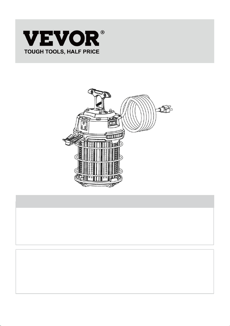
LED WORK LIGHT
INSTRUCTION MANUAL
We continue to be committed to provide you tools with competitive price.
"Save Half", "Half Price" or any other similar expressions used by us only
represents an estimate of savings you might benefit from buying certain tools
with us compared to the major top brands and does not necessarily mean to cover
all categories of tools offered by us. You are kindly reminded to verify carefully
when you are placing an order with us if you are actually Saving
Half in comparison with the top major brands.

- 1 -
MODEL:GT-ZBQW-150W
Have product questions? Need technical support? Please feel free to
contact us:
Technical Support and E-Warranty Certificate
www.vevor.com/support
NEED HELP? CONTACT US!
This is the original instruction, please read all manual instructions
carefully before operating. VEVOR reserves a clear interpretation of our
user manual. The appearance of the product shall be subject to the
product you received. Please forgive us that we won't inform you again if
there are any technology or software updates on our product.
LED WORK LIGHT
- 2 -
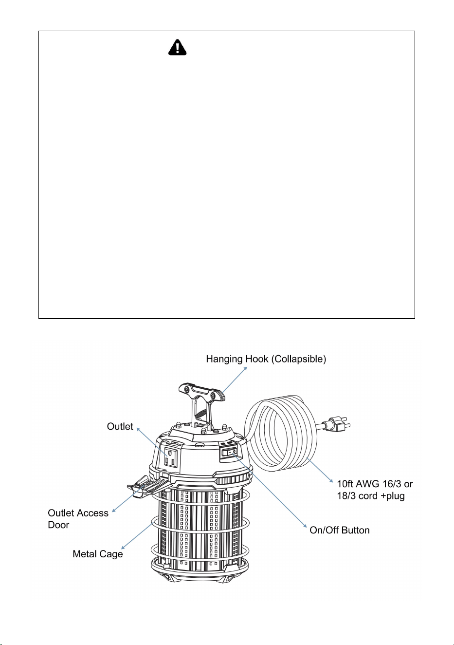
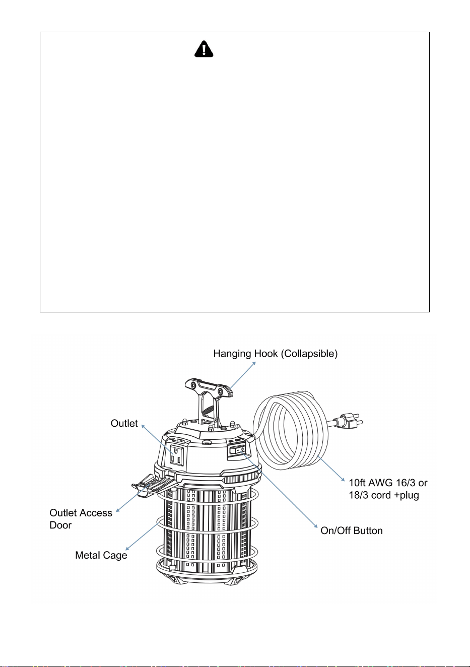
WARNING
RISK OF ELECTRIC SHOCK
IMPORTANT:
READ BEFORE REMOVING FIXTURE FROM CARTON. RETAIN FOR
FUTURE REFERENCE.
— Disconnect electrical power to fixture and follow proper lockout/tag out
procedures before
installation or maintenance. Contact a qualified electrician for installation.
— DO NOT disassemble the fixture.
— Use ONLY in 120VAC, 60Hz circuits.
— Suitable for use in dry or damp location.
— DO NOT use with extension cord near water or wherever water may
accumulate.

- 3 -
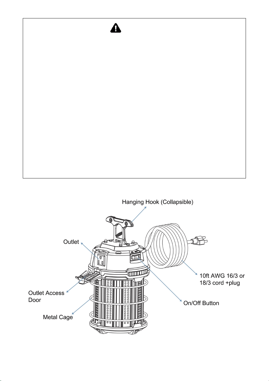
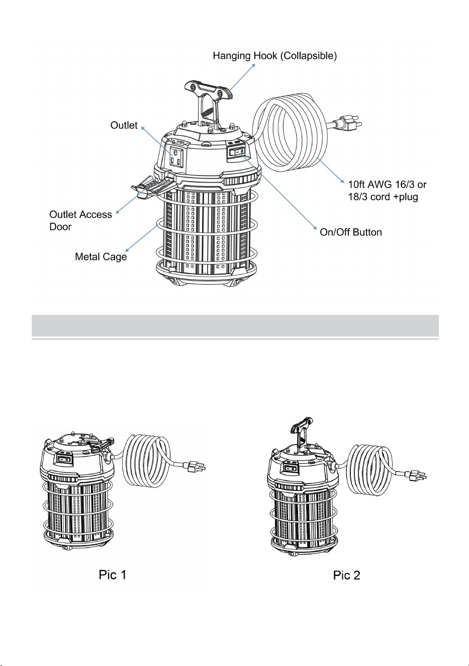
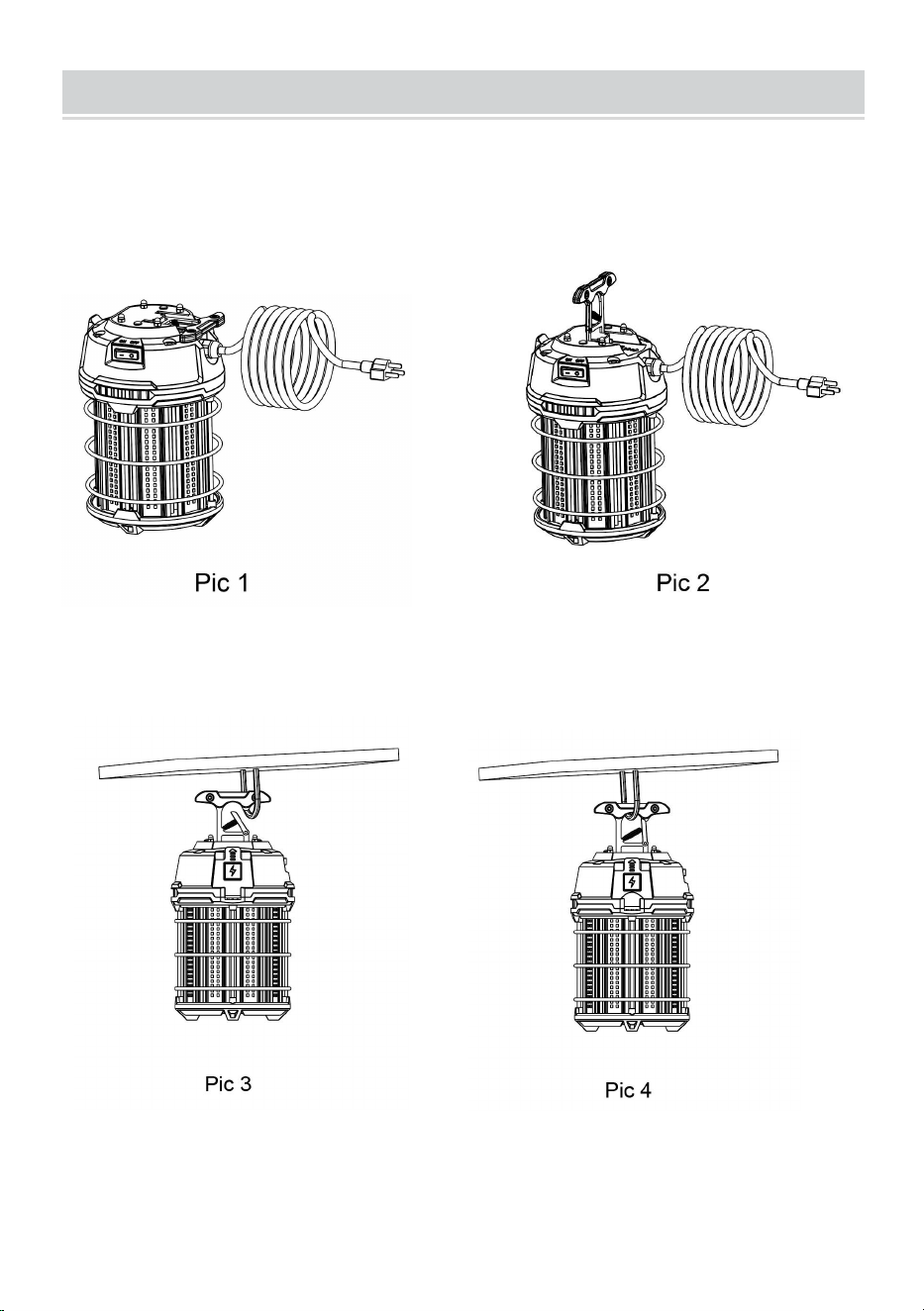
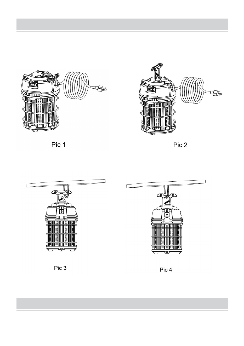
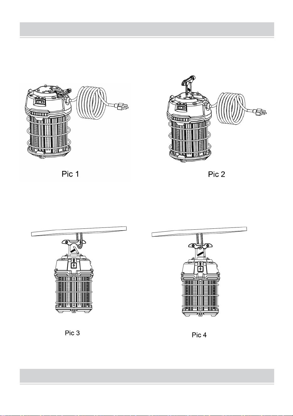
HOOK INSTALLATION
1.Check whether the appearance
of the fixture is in good condition
(Pic 1)
2.Stand the metal hook up (Pic 2)
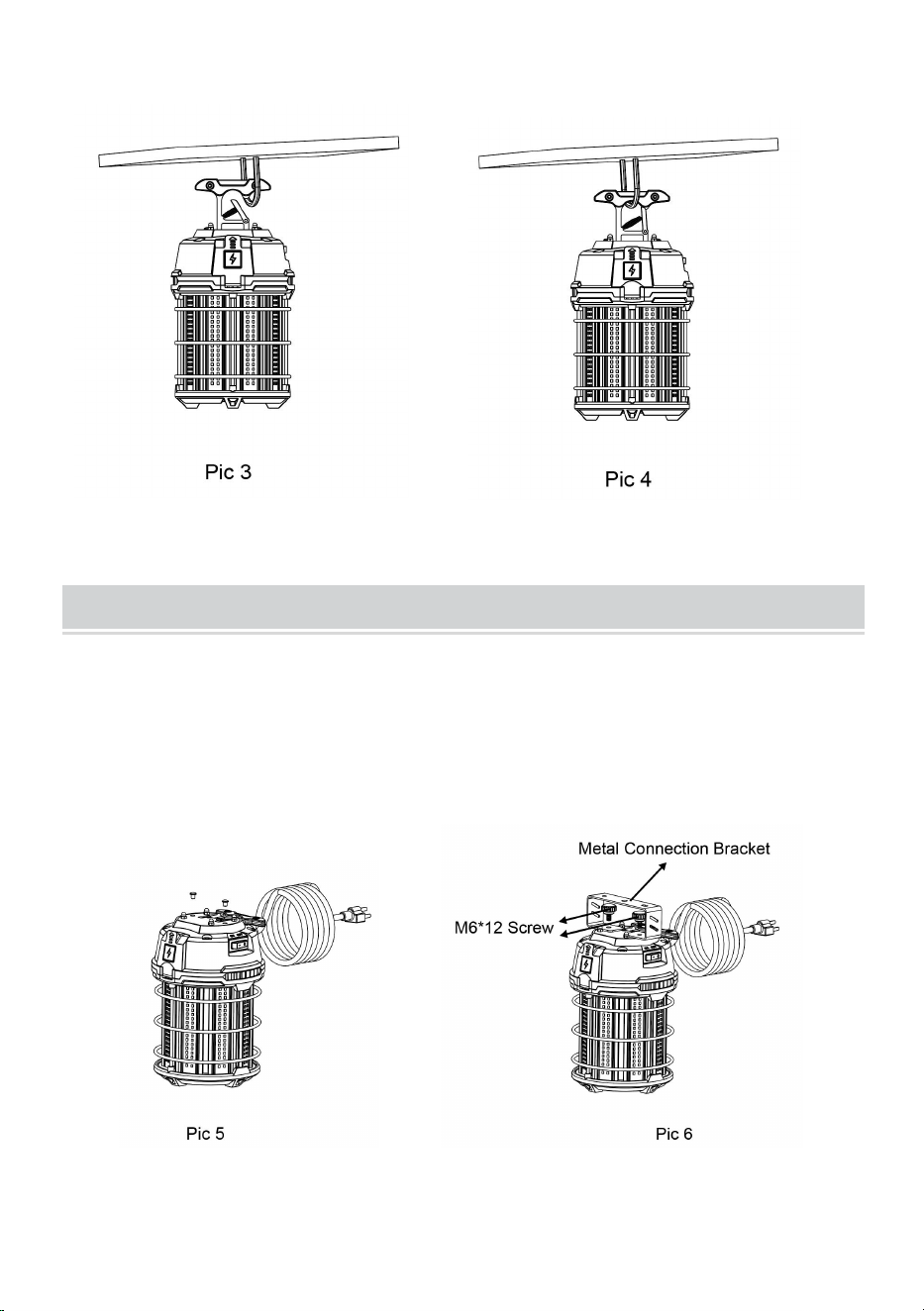
3.Rotate the buckle of the hook
and hang it on the ring or rope (Pic
3)
4.Installation finished (Pic 4)
- 4 -
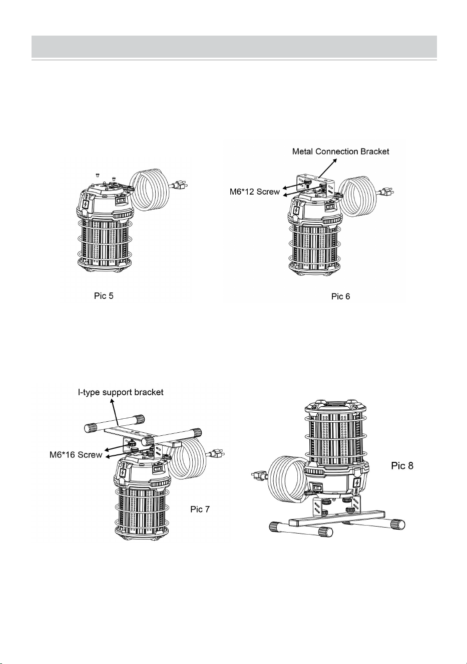
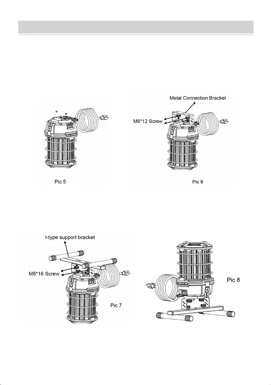
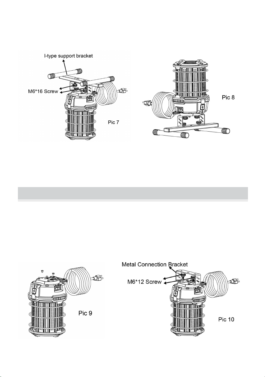
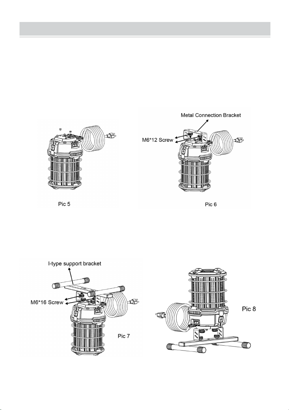
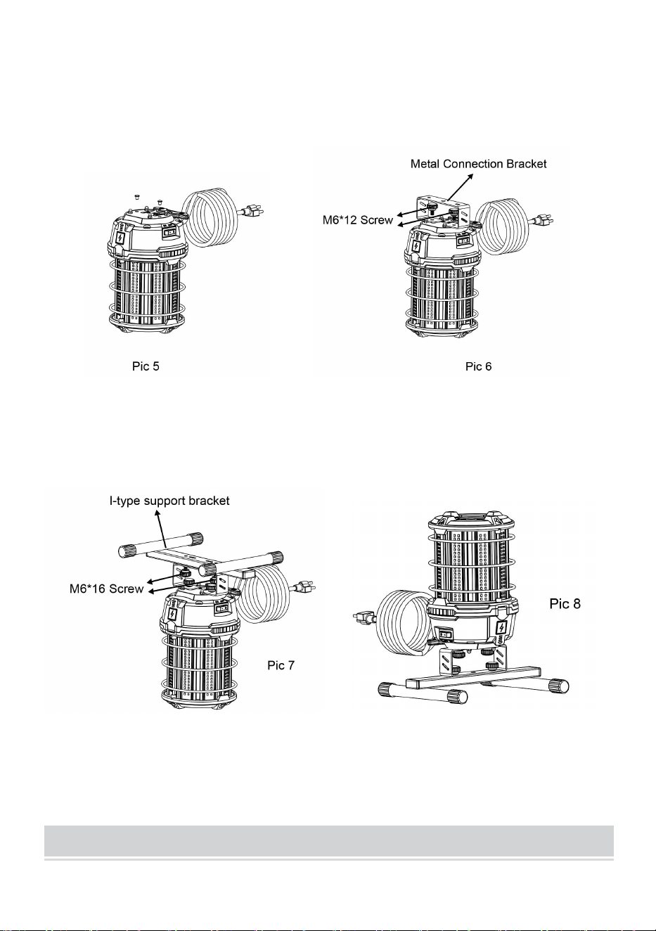
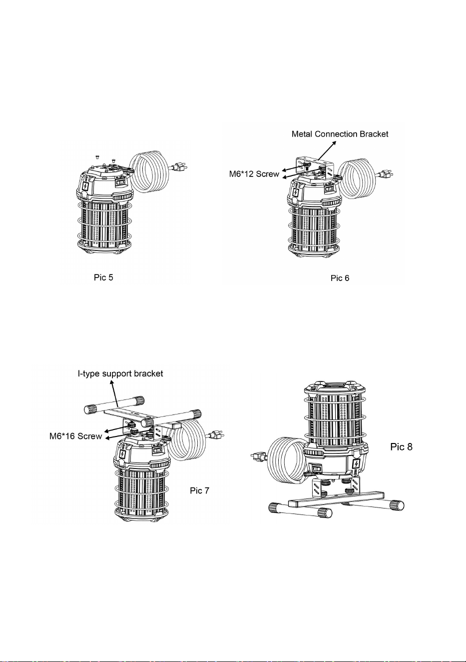
I-TYPE SUPPORT BRACKET INSTALLATION
1.Remove the protective glue
plugs inside the two bracket
mounting holes on the top (Pic 5)
2.Install the metal connection
bracket on the top of the product
with two M6*12 screws (Pic 6)
3. Install the I-type support bracket
with two M6*16 screws on the
connecting bracket (Pic 7)
4. I-type support bracket
installation finished (Pic 8)
- 5 -
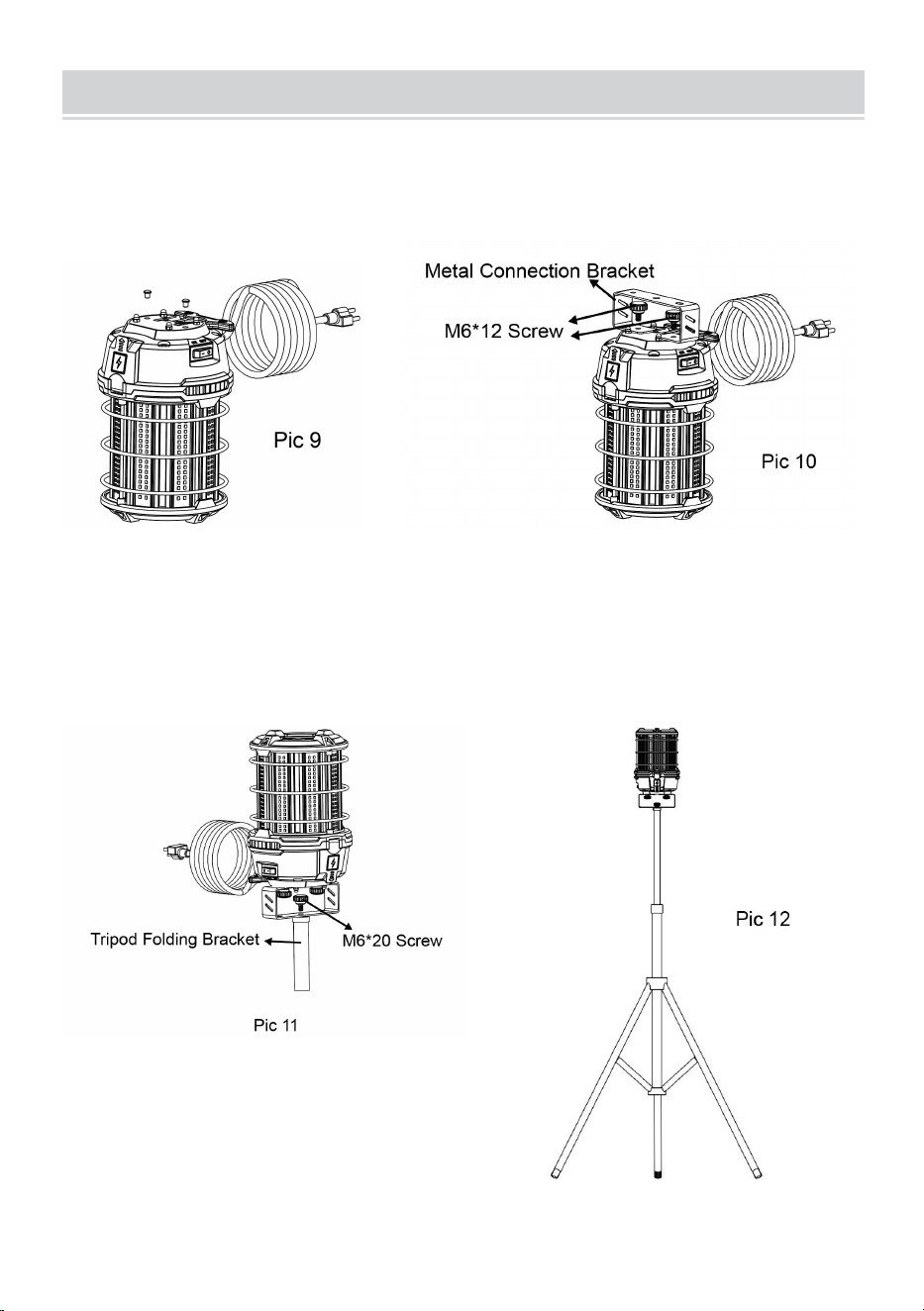
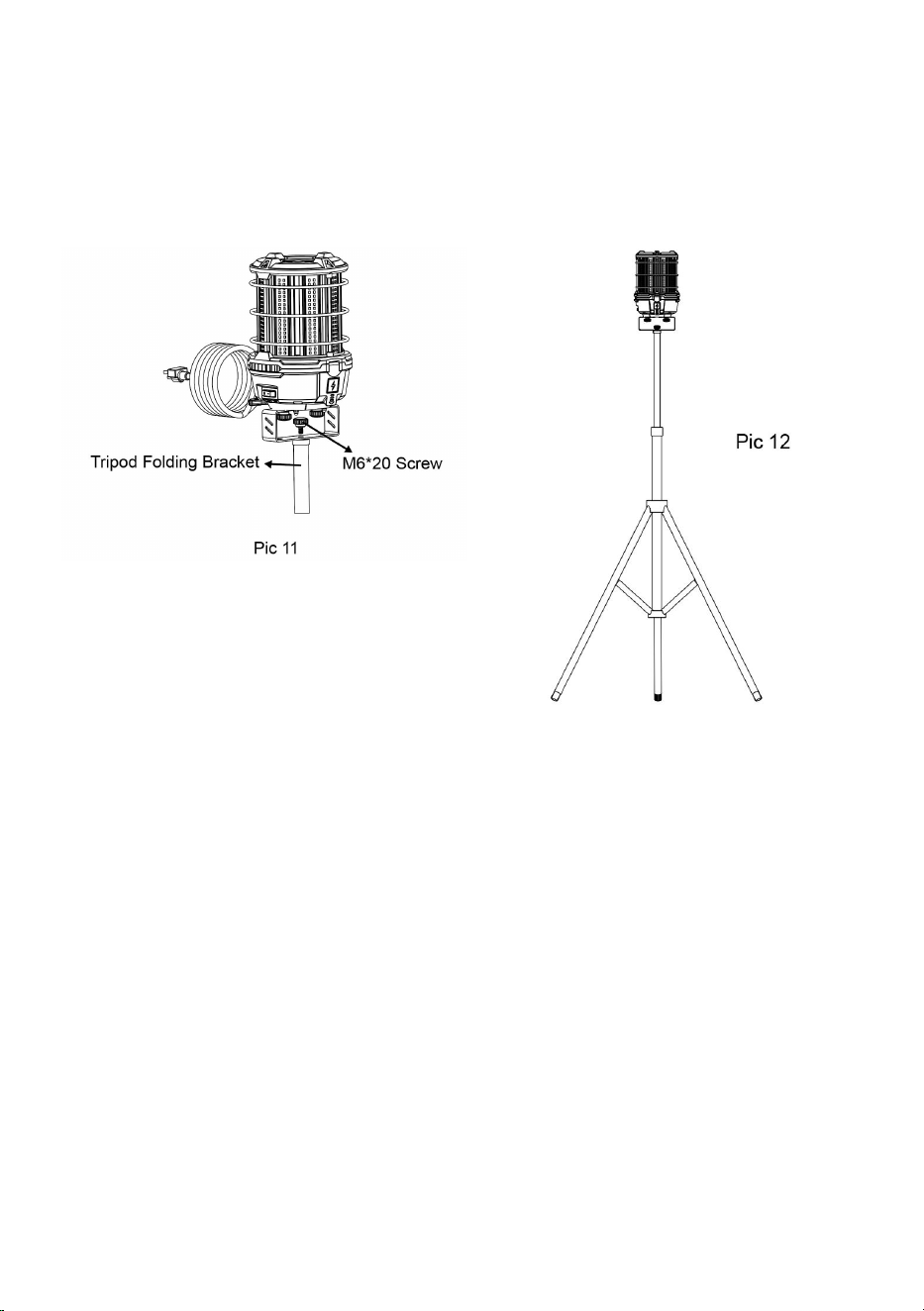
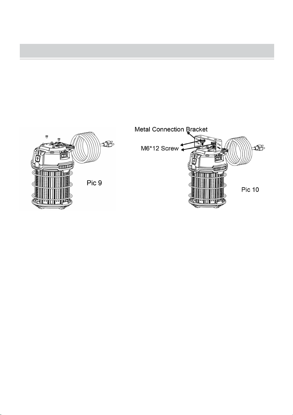
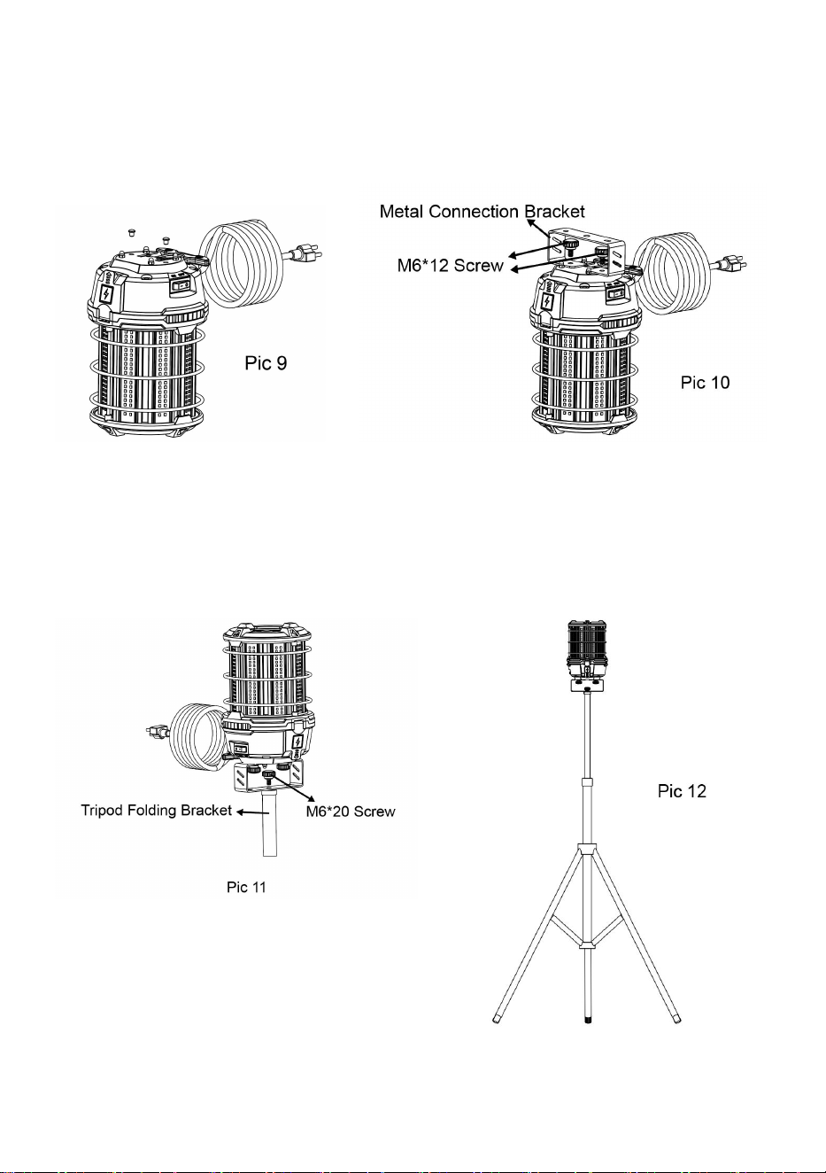
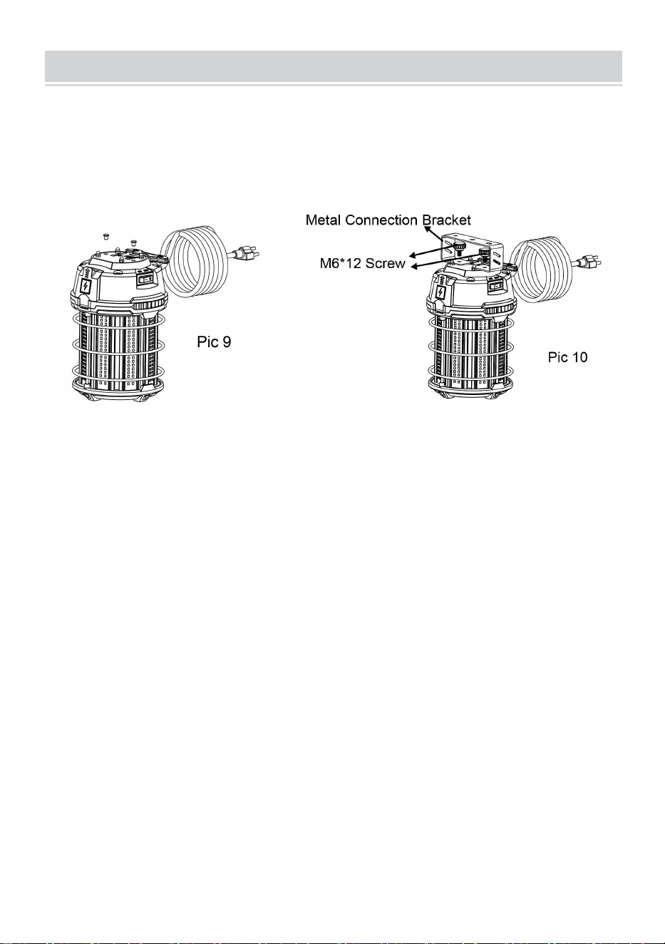
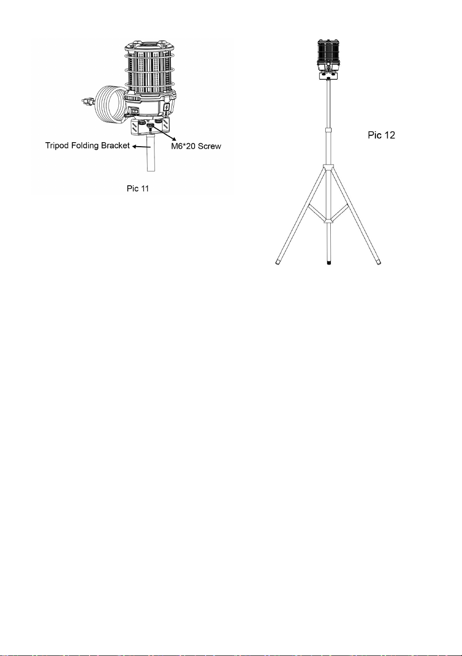
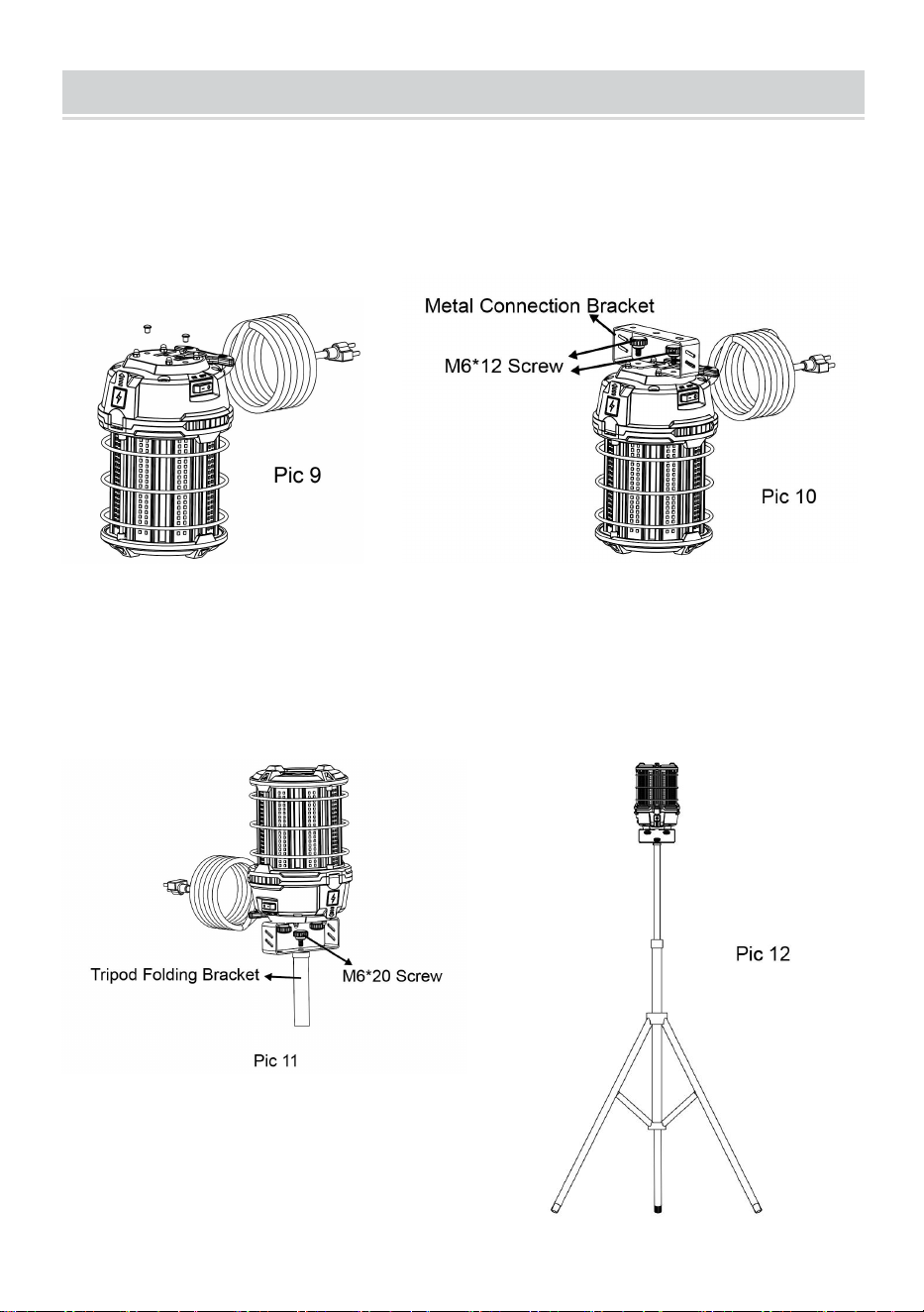
TRIPOD INSTALLATION
1. Remove the protective glue
plugs inside the two bracket
mounting holes on the top (Pic 9)
2. Install the metal connection
bracket on the top of the product
with two M6*12 screws (Pic 10)
3. Install the metal connection bracket
on the tripod folding bracket with one
M6*20 screw (Pic11)
4. Tripod folding bracket
installation finished (Pic 12)
- 6 -
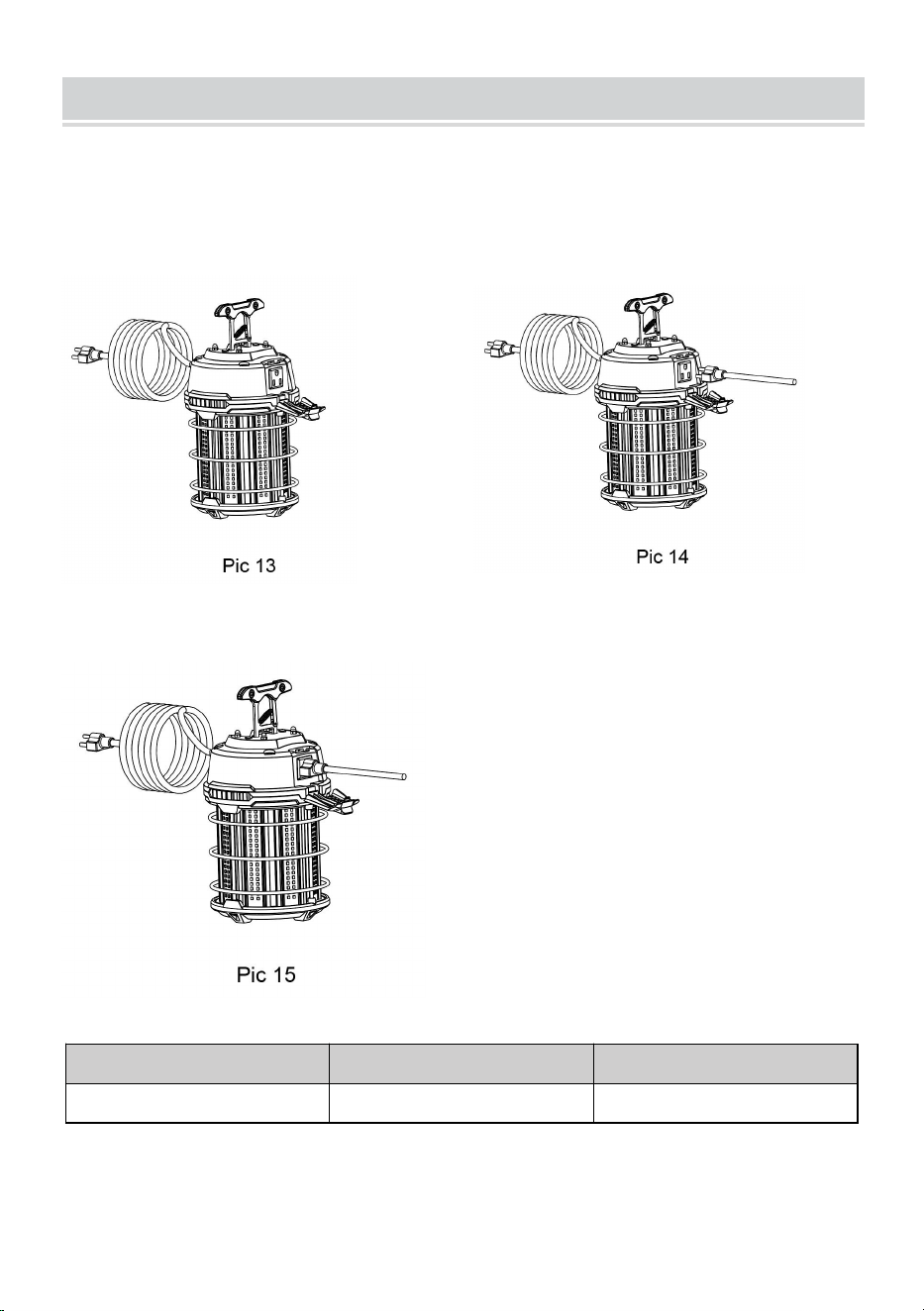
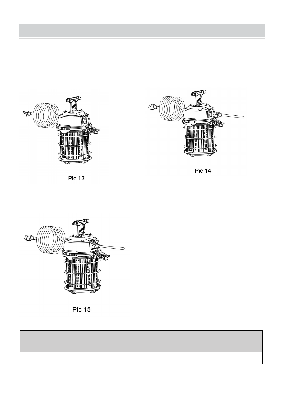
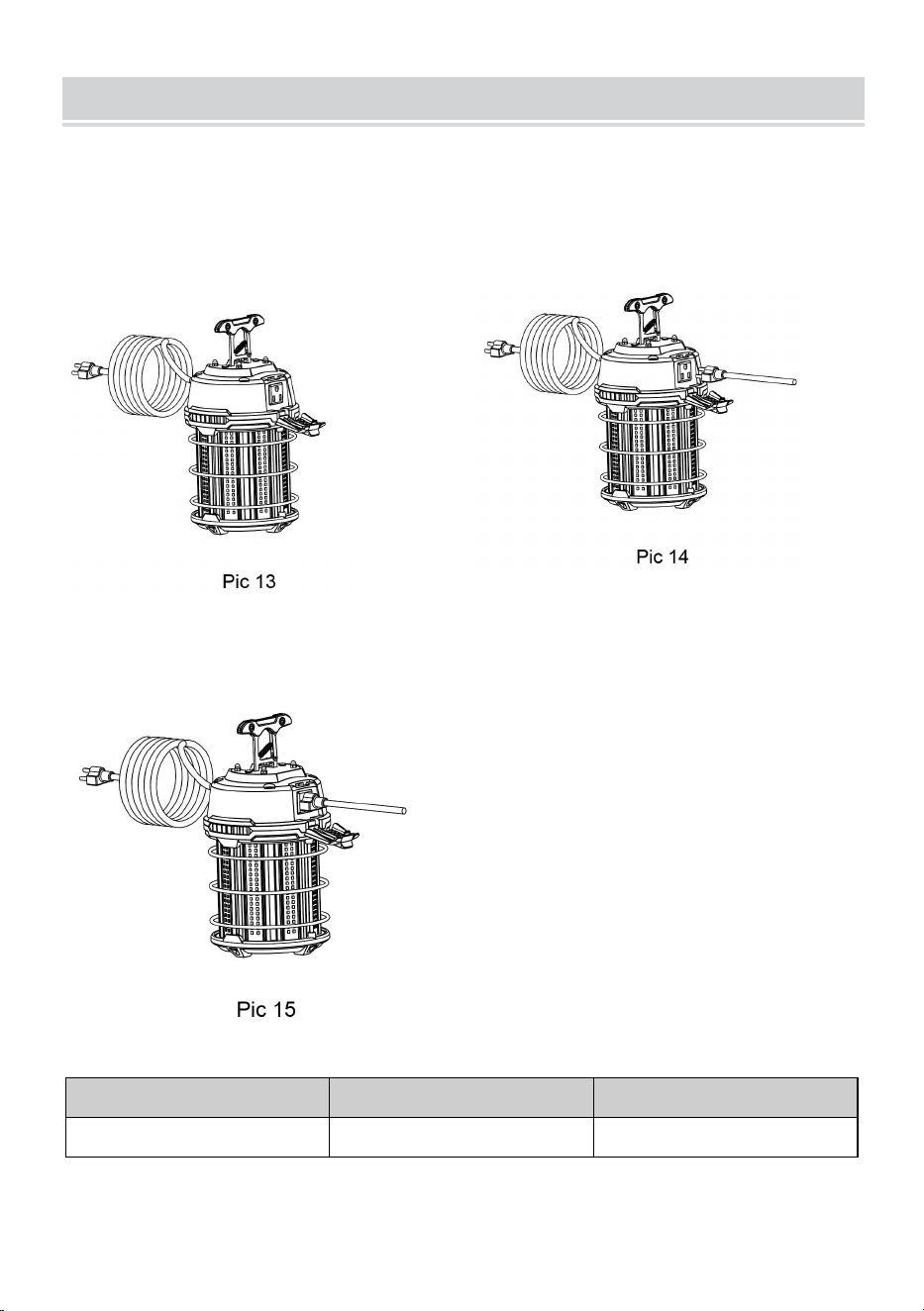
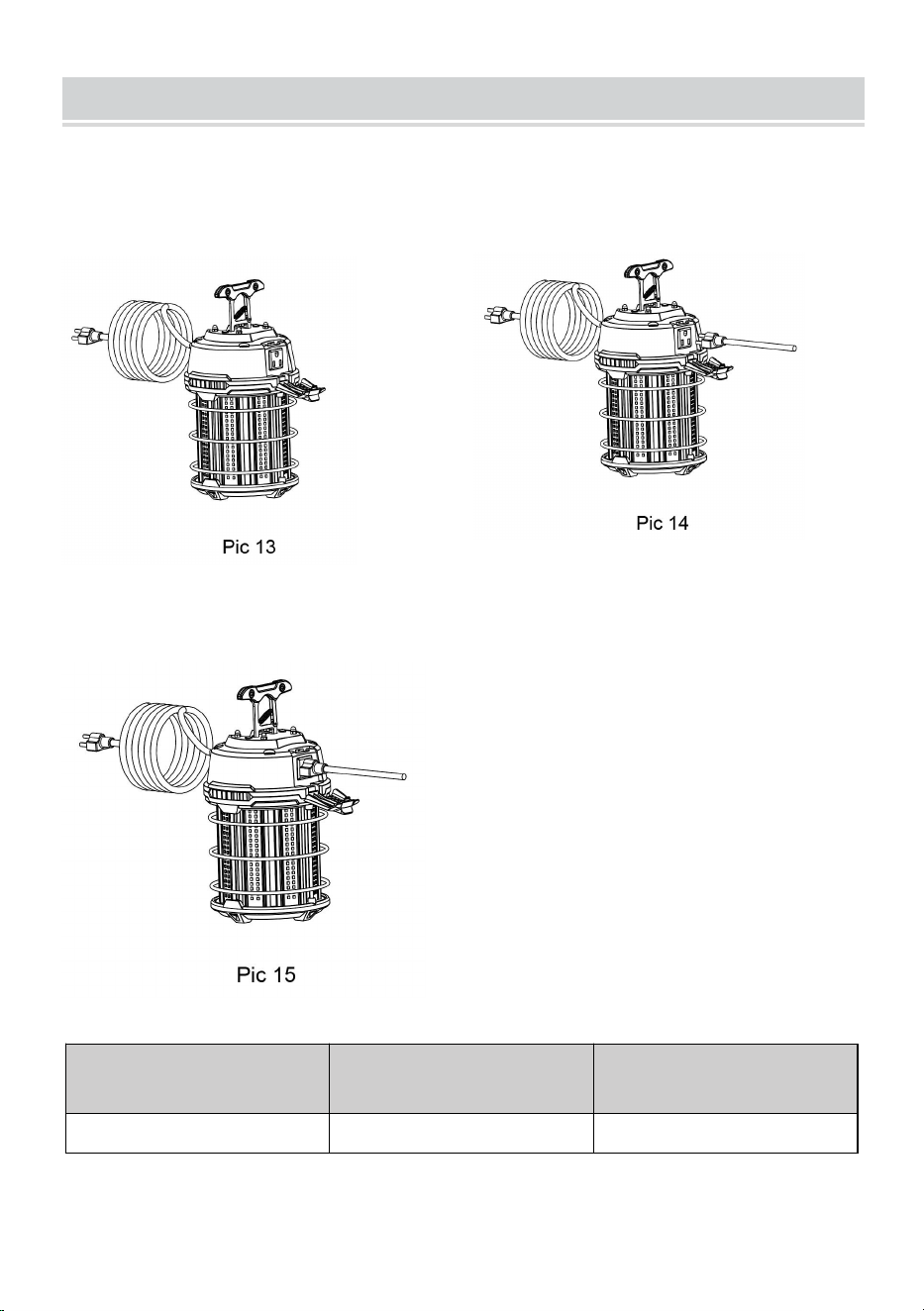
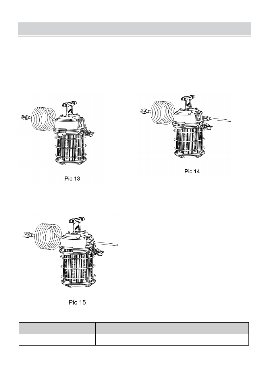
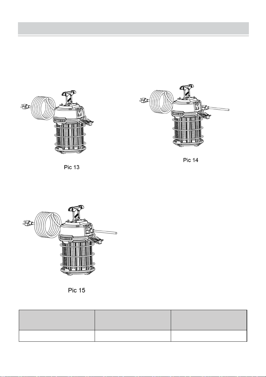
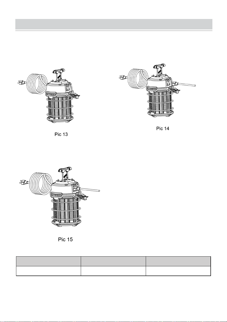
LINKING ADDITIONAL UNITS
1. Turn down to open the protective
cover (Pic 13)
2. Insert the American standard
three-hole plug into the socket (Pic
14)
3. Product linked one by one (Pic 15)
Wattage
UL Current@ 120V(A)
Link-able Qtys
150W
1.5
6pcs


- 8 -
Technique Certificat d'assistance et de garantie électronique
www.vevor.com/support
LAMPE DE TRAVAIL À LED
MANUEL D'INSTRUCTIONS
Nous continuons à nous engager à vous fournir des outils à des prix compétitifs.
« Économisez la moitié », « Moitié prix » ou toute autre expression similaire utilisée par
nous uniquement
représente une estimation des économies dont vous pourriez bénéficier en achetant
certains outils
avec nous par rapport aux grandes marques et ne signifie pas nécessairement couverture
toutes les catégories d'outils que nous proposons. Nous vous rappelons de bien vouloir
vérifier soigneusement
lorsque vous passez une commande chez nous si vous êtes réellement Économie
Moitié par rapport aux plus grandes marques.

- 9 -

- 1 -
MODÈLE : GT-ZBQW-150W
Have product questions? Need technical support? Please feel free to
contact us:
Technical Support and E-Warranty Certificate
www.vevor.com/support
NEED HELP? CONTACT US!
This is the original instruction, please read all manual instructions
carefully before operating. VEVOR reserves a clear interpretation of our
user manual. The appearance of the product shall be subject to the
product you received. Please forgive us that we won't inform you again if
there are any technology or software updates on our product.
LED WORK LIGHT
- 2 -
AVERTISSEMENT
RISQUE DE CHOC ÉLECTRIQUE
IMPORTANT:
À LIRE AVANT DE RETIRER LE LUMINAIRE DU CARTON. CONSERVER
POUR RÉFÉRENCE ULTÉRIEURE.
— Débranchez l'alimentation électrique de l'appareil et suivez les
procédures de verrouillage/étiquetage appropriées avant
installation ou entretien. Contactez un électricien qualifié pour l'installation.
— NE PAS démonter le luminaire.
— Utiliser UNIQUEMENT dans des circuits 120 VCA, 60 Hz.
— Convient pour une utilisation dans un endroit sec ou humide.
— NE PAS utiliser avec une rallonge à proximité de l’eau ou dans un endroit
où l’eau peut s’accumuler.

- 3 -
HOOK INSTALLATION
1.Vérifiez si l'apparence du
luminaire est en bon état état
(Photo 1)
2. Placez le crochet métallique
debout (photo 2)
3. Faites tourner la boucle du
crochet et accrochez-le à l'anneau
ou à la corde (Photo 3)
4.Installation terminée (Photo 4)
- 4 -
I-TYPE SUPPORT BRACKET INSTALLATION
1. Retirez les bouchons de colle
protecteurs à l'intérieur du deux
trous de montage du support sur le
dessus (Photo 5)
2. Installez le support de
connexion métallique sur le dessus
du produit avec deux vis M6*12
(Photo 6)
3. Installez le support de type I
avec deux vis M6*16 sur le support
de connexion (Pic 7)
4. Installation du support de type I
terminée (photo 8)

- 5 -
TRIPOD INSTALLATION
1. Retirez les bouchons de
protection en colle à l'intérieur des
deux trous de montage du support
sur le dessus (Photo 9)
2. Installez le support de
connexion métallique sur le dessus
du produit avec deux vis M6*12
(Photo 10)
3. Installez le support de connexion
métallique sur le support pliable du
trépied avec une vis M6*20 (Pic11)
4. Installation du support pliable
du trépied terminée (photo 12)
- 6 -
LINKING ADDITIONAL UNITS
1. Tournez vers le bas pour ouvrir le
couvercle de protection (Photo 13)
2. Insérez la fiche standard
américaine à trois trous dans la
prise (photo 14)
3. Produits liés un par un (Photo 15)
Puissance
Courant UL à 120 V (A)
Quantités pouvant être
liées
150 W
1,5
6 pièces


- 8 -
Technisch Support und E-Garantie-Zertifikat www.vevor.com/support
LED-ARBEITSLICHT
BEDIENUNGSANLEITUNG
Wir sind weiterhin bestrebt, Ihnen Werkzeuge zu wettbewerbsfähigen Preisen anzubieten.
"Sparen Sie die Hälfte", "Halber Preis" oder andere ähnliche Ausdrücke, die wir nur
verwenden
stellt eine Schätzung der Einsparungen dar, die Sie durch den Kauf bestimmter Werkzeuge
erzielen können
mit uns im Vergleich zu den großen Top-Marken und bedeutet nicht unbedingt, Abdeckung
alle von uns angebotenen Werkzeugkategorien. Wir möchten Sie bitten, zu überprüfen
sorgfältig
wenn Sie bei uns eine Bestellung aufgeben, wenn Sie tatsächlich Speichern
Hälfte im Vergleich mit den Top-Großmarken.

- 9 -

- 1 -
MODELL: GT-ZBQW-150W
Have product questions? Need technical support? Please feel free to
contact us:
Technical Support and E-Warranty Certificate
www.vevor.com/support
NEED HELP? CONTACT US!
This is the original instruction, please read all manual instructions
carefully before operating. VEVOR reserves a clear interpretation of our
user manual. The appearance of the product shall be subject to the
product you received. Please forgive us that we won't inform you again if
there are any technology or software updates on our product.
LED WORK LIGHT

- 2 -
WARNUNG
STROMSCHLAGGEFAHR
WICHTIG:
LESEN SIE DIESE HINWEISE, BEVOR SIE DIE LEUCHTMITTEL AUS
DEM KARTON NEHMEN. BEWAHREN SIE SIE ZUM SPÄTEREN
NACHSCHLAGEN AUF.
— Trennen Sie die Stromversorgung zum Gerät und befolgen Sie die
entsprechenden Sperr-/Kennzeichnungsverfahren, bevor Sie
Installation oder Wartung. Wenden Sie sich für die Installation an einen
qualifizierten Elektriker.
— Das Gerät NICHT auseinandernehmen.
— NUR in Stromkreisen mit 120 V Wechselstrom und 60 Hz verwenden.
— Geeignet für den Einsatz in trockenen und feuchten Räumen.
— Verwenden Sie das Verlängerungskabel NICHT in der Nähe von Wasser
oder an Orten, an denen sich Wasser ansammeln kann.
- 3 -
HOOK INSTALLATION
1.Überprüfen Sie, ob das
Erscheinungsbild der Leuchte in
Ordnung ist Zustand (Bild 1)
2. Stellen Sie den Metallhaken auf
(Bild 2)
3. Drehen Sie die Schnalle des
Hakens und hängen Sie ihn an den
Ring oder das Seil (Bild 3)
- 4 -
4.Installation abgeschlossen (Bild
4)
I-TYPE SUPPORT BRACKET INSTALLATION
1. Entfernen Sie die Schutzstopfen
im Inneren des zwei
Halterungsbefestigungslöcher auf
der Oberseite (Bild 5)
2. Befestigen Sie die
Metallverbindungshalterung mit
zwei M6*12-Schrauben oben am
Produkt (Bild 6).
3. Installieren Sie die
I-Typ-Halterung mit zwei
- 5 -
M6*16-Schrauben an der
Anschlusshalterung (Bild 7)
4. Installation der
I-Typ-Stützhalterung
abgeschlossen (Bild 8)
TRIPOD INSTALLATION
1. Entfernen Sie die
Schutzklebestopfen in den beiden
oberen
Halterungsbefestigungslöchern
(Bild 9).
2. Befestigen Sie die
Metallverbindungshalterung mit
zwei M6*12-Schrauben oben am
Produkt (Bild 10).
- 6 -
3. Befestigen Sie die
Metallverbindungshalterung mit einer
M6*20-Schraube an der
Stativklapphalterung (Bild 11).
4. Installation der
Stativklapphalterung
abgeschlossen (Bild 12)
- 7 -
LINKING ADDITIONAL UNITS
1. Schutzabdeckung nach unten
drehen und öffnen (Bild 13)
2. Stecken Sie den amerikanischen
Standard-Dreilochstecker in die
Steckdose (Bild 14)
3. Produkt einzeln verlinkt (Bild 15)
Leistung
UL-Strom bei 120 V (A)
Verknüpfbare Mengen
150 W
1.5
6 Stück


- 9 -
Tecnico Supporto e certificato di garanzia elettronica www.vevor.com/support
LUCE DA LAVORO A LED
MANUALE DI ISTRUZIONI
Continuiamo a impegnarci per fornirvi strumenti a prezzi competitivi.
"Risparmia la metà", "Metà prezzo" o altre espressioni simili utilizzate solo da noi
rappresenta una stima dei risparmi che potresti ottenere acquistando determinati strumenti
con noi rispetto ai principali marchi top e non significa necessariamente copertina
tutte le categorie di strumenti da noi offerti. Ti ricordiamo cortesemente di verificare
accuratamente
quando effettui un ordine con noi se sei effettivamente Risparmio
Metà rispetto ai marchi più importanti.

- 10 -

- 1 -
MODELLO: GT-ZBQW-150W
Have product questions? Need technical support? Please feel free to
contact us:
Technical Support and E-Warranty Certificate
www.vevor.com/support
NEED HELP? CONTACT US!
This is the original instruction, please read all manual instructions
carefully before operating. VEVOR reserves a clear interpretation of our
user manual. The appearance of the product shall be subject to the
product you received. Please forgive us that we won't inform you again if
there are any technology or software updates on our product.
LED WORK LIGHT
- 2 -
AVVERTIMENTO
RISCHIO DI SCOSSA ELETTRICA
IMPORTANTE:
LEGGERE PRIMA DI RIMUOVERE L'APPARECCHIO DALLA SCATOLA.
CONSERVARE PER RIFERIMENTO FUTURO.
— Scollegare l'alimentazione elettrica dall'apparecchio e seguire le
procedure di blocco/etichettatura appropriate prima
installazione o manutenzione. Contattare un elettricista qualificato per
l'installazione.
— NON smontare l'apparecchio.
— Utilizzare SOLO in circuiti da 120 V CA, 60 Hz.
— Adatto all'uso in luoghi asciutti o umidi.
— NON utilizzare con una prolunga vicino all'acqua o in qualsiasi luogo in
cui possa accumularsi acqua.
- 3 -
HOOK INSTALLATION
1. Controllare se l'aspetto
dell'apparecchio è buono
condizione (Foto 1)
2. Posizionare il gancio metallico in
posizione verticale (foto 2)
3. Ruotare la fibbia del gancio e
appenderla all'anello o alla corda
(foto 3)
4. Installazione completata (Foto 4)

- 4 -
I-TYPE SUPPORT BRACKET INSTALLATION
1. Rimuovere i tappi di colla
protettiva all'interno del due fori di
montaggio della staffa nella parte
superiore (foto 5)
2. Installare la staffa di
collegamento in metallo sulla parte
superiore del prodotto con due viti
M6*12 (immagine 6)
3. Installare la staffa di supporto di
tipo I con due viti M6*16 sulla staffa
di collegamento (Foto 7)
4. Installazione della staffa di
supporto tipo I completata
(immagine 8)

- 5 -
TRIPOD INSTALLATION
1. Rimuovere i tappi di protezione
della colla all'interno dei due fori di
montaggio della staffa nella parte
superiore (foto 9)
2. Installare la staffa di
collegamento in metallo sulla parte
superiore del prodotto con due viti
M6*12 (immagine 10)
3. Installare la staffa di collegamento
in metallo sulla staffa pieghevole del
treppiede con una vite M6*20 (Fig.11)
4. Completamento
dell'installazione della staffa
pieghevole del treppiede
(immagine 12)

- 6 -
- 7 -
LINKING ADDITIONAL UNITS
1. Ruotare verso il basso per aprire
il coperchio protettivo (foto 13)
2. Inserire la spina americana a tre
fori nella presa (foto 14)
3. Prodotto collegato uno per uno (Immagine 15)
Potenza
Corrente UL a 120 V
(A)
Qtà collegabili
150W
1.5
6 pezzi


- 9 -
Técnico Soporte y certificado de garantía electrónica www.vevor.com/support
LUZ DE TRABAJO LED
MANUAL DE INSTRUCCIONES
Seguimos comprometidos a brindarle herramientas a precios competitivos.
"Ahorra la mitad", "mitad de precio" o cualquier otra expresión similar utilizada únicamente
por nosotros
Representa una estimación de los ahorros que podría obtener al comprar ciertas
herramientas.
con nosotros en comparación con las principales marcas líderes y no significa
necesariamente cubrir
Todas las categorías de herramientas que ofrecemos. Le recordamos que debe verificar
con cuidado
Cuando realiza un pedido con nosotros, si realmente está Ahorro
Medio en comparación con las principales marcas líderes.

- 10 -

- 1 -
MODELO: GT-ZBQW-150W
Have product questions? Need technical support? Please feel free to
contact us:
Technical Support and E-Warranty Certificate
www.vevor.com/support
NEED HELP? CONTACT US!
This is the original instruction, please read all manual instructions
carefully before operating. VEVOR reserves a clear interpretation of our
user manual. The appearance of the product shall be subject to the
product you received. Please forgive us that we won't inform you again if
there are any technology or software updates on our product.
LED WORK LIGHT
- 2 -
ADVERTENCIA
RIESGO DE DESCARGA ELÉCTRICA
IMPORTANTE:
LEA ANTES DE SACAR EL ACCESORIO DE LA CAJA. CONSÉRVELO
PARA FUTURAS CONSULTAS.
— Desconecte la energía eléctrica del artefacto y siga los procedimientos
adecuados de bloqueo y etiquetado antes
Instalación o mantenimiento. Contacte a un electricista calificado para la
instalación.
— NO desmonte el aparato.
—Utilizar ÚNICAMENTE en circuitos de 120 V CA, 60 Hz.
— Adecuado para uso en lugares secos o húmedos.
— NO utilice el cable de extensión cerca del agua o en cualquier lugar
donde pueda acumularse agua.

- 3 -
HOOK INSTALLATION
1. Verifique si la apariencia del
accesorio es buena. Estado (Foto
1)
2. Coloque el gancho de metal en
posición vertical (Imagen 2)
3. Gire la hebilla del gancho y
cuélguelo en el anillo o cuerda
(Imagen 3)
4.Instalación finalizada (Foto 4)
- 4 -
I-TYPE SUPPORT BRACKET INSTALLATION
1. Retire los tapones de
pegamento protectores del interior
del Dos orificios de montaje del
soporte en la parte superior
(imagen 5)
2. Instale el soporte de conexión
de metal en la parte superior del
producto con dos tornillos M6*12
(Imagen 6)
3. Instale el soporte tipo I con dos
tornillos M6*16 en el soporte de
conexión (Imagen 7)
4. Finalizada la instalación del
soporte tipo I (Imagen 8)
- 5 -
TRIPOD INSTALLATION
1. Retire los tapones de
pegamento protectores dentro de
los dos orificios de montaje del
soporte en la parte superior
(Imagen 9)
2. Instale el soporte de conexión
de metal en la parte superior del
producto con dos tornillos M6*12
(Imagen 10)
3. Instale el soporte de conexión de
metal en el soporte plegable del
trípode con un tornillo M6*20 (Imagen
11)
4. Finalizada la instalación del
soporte plegable para trípode
(Imagen 12)

- 6 -

- 7 -
LINKING ADDITIONAL UNITS
1. Gire hacia abajo para abrir la
cubierta protectora (Imagen 13)
2. Inserte el enchufe de tres orificios
estándar americano en la toma
(Imagen 14)
3. Producto vinculado uno a uno (Imagen 15)
Potencia
Corriente UL a 120
V(A)
Cantidades enlazables
150 W
1.5
6 piezas


- 9 -
Techniczny Wsparcie i certyfikat gwarancji elektronicznej www.vevor.com/support
LAMPA ROBOCZA LED
INSTRUKCJA OBSŁUGI
Nadal staramy się oferować Państwu narzędzia w konkurencyjnych cenach.
„Oszczędź połowę”, „Połowa ceny” lub jakiekolwiek inne podobne wyrażenia używane
wyłącznie przez nas
przedstawia szacunkowe oszczędności, jakie możesz uzyskać kupując określone
narzędzia
z nami w porównaniu do głównych, najlepszych marek i niekoniecznie oznacza to okładka
wszystkie kategorie narzędzi oferowanych przez nas. Przypominamy o sprawdzeniu
ostrożnie
gdy składasz u nas zamówienie, jeśli faktycznie Oszczędność
Połowa w porównaniu z wiodącymi markami.

- 10 -
- 1 -
MODEL: GT-ZBQW-150W
Have product questions? Need technical support? Please feel free to
contact us:
Technical Support and E-Warranty Certificate
www.vevor.com/support
NEED HELP? CONTACT US!
This is the original instruction, please read all manual instructions
carefully before operating. VEVOR reserves a clear interpretation of our
user manual. The appearance of the product shall be subject to the
product you received. Please forgive us that we won't inform you again if
there are any technology or software updates on our product.
LED WORK LIGHT
- 2 -
OSTRZEŻENIE
RYZYKO PORAŻENIA PRĄDEM ELEKTRYCZNYM
WAŻNY:
PRZECZYTAJ PRZED WYJĘCIEM URZĄDZENIA Z OPAKOWANIA.
ZACHOWAJ DO PRZYSZŁOŚCI.
— Przed przystąpieniem do prac odłącz zasilanie elektryczne urządzenia i
wykonaj odpowiednie procedury blokowania/oznaczania.
instalacja lub konserwacja. Skontaktuj się z wykwalifikowanym elektrykiem
w celu instalacji.
— NIE rozmontowuj urządzenia.
— Stosować TYLKO w obwodach 120 V AC, 60 Hz.
— Nadaje się do stosowania w pomieszczeniach suchych i wilgotnych.
— NIE używać przedłużacza w pobliżu wody lub w innych miejscach, w
których może gromadzić się woda.
- 3 -
HOOK INSTALLATION
1.Sprawdź, czy wygląd oprawy jest
dobry stan (fot. 1)
2. Postaw metalowy hak (rys. 2)
3. Obróć klamrę haka i zawieś ją
na kółku lub linie (rys. 3)
4. Instalacja zakończona (fot. 4)
I-TYPE SUPPORT BRACKET INSTALLATION
- 4 -
1. Usuń ochronne zatyczki klejowe
znajdujące się wewnątrz dwa
otwory montażowe uchwytu na
górze (fot. 5)
2. Zamontuj metalowy uchwyt
łączący na górze produktu za
pomocą dwóch śrub M6*12 (rys. 6)
3. Zamontuj wspornik typu I za
pomocą dwóch śrub M6*16 na
uchwycie łączącym (fot. 7)
4. Zakończono montaż wspornika
typu I (rys. 8)
TRIPOD INSTALLATION
- 5 -
1. Usuń ochronne zaślepki klejowe
znajdujące się wewnątrz dwóch
otworów montażowych wspornika
na górze (rys. 9)
2. Zamontuj metalowy uchwyt
łączący na górze produktu za
pomocą dwóch śrub M6*12 (rys.
10)
3. Zamontuj metalowy uchwyt łączący
na składanym uchwycie statywu za
pomocą jednej śruby M6*20 (Rys. 11)
4. Montaż składanego uchwytu
statywu zakończony (fot. 12)
- 6 -
LINKING ADDITIONAL UNITS
1. Obróć w dół, aby otworzyć
pokrywę ochronną (rys. 13)
2. Włóż standardową amerykańską
wtyczkę trzyotworową do gniazdka
(rys. 14)
3. Produkty połączone jeden po drugim (Rys. 15)
Moc
Prąd UL @ 120 V(A)
Łączone ilości
150 W
1,5
6 szt.


- 8 -
Technisch Ondersteuning en E-garantiecertificaat www.vevor.com/support
LED WERKLAMP
GEBRUIKSAANWIJZING
Wij streven er voortdurend naar om u gereedschappen tegen concurrerende prijzen te
leveren.
"Bespaar de helft", "halve prijs" of andere soortgelijke uitdrukkingen die alleen door ons
worden gebruikt
geeft een schatting van de besparingen die u kunt behalen door bepaalde gereedschappen
te kopen
bij ons vergeleken met de grote topmerken en betekent niet per se dat omslag
alle categorieën van tools die wij aanbieden. U wordt vriendelijk verzocht om te verifiëren
voorzichtig
wanneer u een bestelling bij ons plaatst, als u daadwerkelijk Besparing
Half in vergelijking met de grote topmerken.

- 9 -

- 1 -
MODEL: GT-ZBQW-150W
Have product questions? Need technical support? Please feel free to
contact us:
Technical Support and E-Warranty Certificate
www.vevor.com/support
NEED HELP? CONTACT US!
This is the original instruction, please read all manual instructions
carefully before operating. VEVOR reserves a clear interpretation of our
user manual. The appearance of the product shall be subject to the
product you received. Please forgive us that we won't inform you again if
there are any technology or software updates on our product.
LED WORK LIGHT

- 2 -
WAARSCHUWING
RISICO OP ELEKTRISCHE SCHOK
BELANGRIJK:
LEES DIT VOORDAT U HET APPARAAT UIT DE DOOS HAALT. BEWAAR
VOOR TOEKOMSTIGE RAADPLEGING.
— Koppel de elektrische stroom naar het armatuur los en volg de juiste
lockout/tagout-procedures voordat u
installatie of onderhoud. Neem contact op met een gekwalificeerde
elektricien voor installatie.
— Haal het armatuur NIET uit elkaar.
— ALLEEN gebruiken in circuits van 120 VAC, 60 Hz.
— Geschikt voor gebruik op droge of vochtige locaties.
— Gebruik het apparaat NIET met een verlengsnoer in de buurt van water of
op een plek waar zich water kan verzamelen.

- 3 -
HOOK INSTALLATION
1. Controleer of het uiterlijk van het
armatuur in goede staat is conditie
(foto 1)
2. Zet de metalen haak rechtop
(foto 2)
3. Draai de gesp van de haak en
hang deze aan de ring of het touw
(foto 3)
4.Installatie voltooid (Foto 4)

- 4 -
I-TYPE SUPPORT BRACKET INSTALLATION
1. Verwijder de beschermende
lijmpluggen aan de binnenkant van
de twee bevestigingsgaten voor de
beugel aan de bovenkant (foto 5)
2. Monteer de metalen
verbindingsbeugel aan de
bovenkant van het product met
twee M6*12 schroeven (foto 6)
3. Installeer de I-type steunbeugel
met twee M6*16 schroeven op de
verbindingsbeugel (foto 7)
4. Installatie van de I-type
steunbeugel is voltooid (foto 8)
- 5 -
TRIPOD INSTALLATION
1. Verwijder de beschermende
lijmpluggen in de twee
bevestigingsgaten van de beugel
aan de bovenkant (foto 9)
2. Monteer de metalen
verbindingsbeugel aan de
bovenkant van het product met
twee M6*12 schroeven (foto 10)
3. Installeer de metalen
verbindingsbeugel op de
statiefvouwbeugel met één
M6*20-schroef (foto 11)
4. Installatie van de opvouwbare
statiefbeugel is voltooid (foto 12)
- 6 -
- 7 -
LINKING ADDITIONAL UNITS
1. Draai naar beneden om de
beschermkap te openen (foto 13)
2. Steek de Amerikaanse standaard
driegatsstekker in het stopcontact
(foto 14)
3. Producten één voor één gekoppeld (foto 15)
Vermogen
UL-stroom bij 120 V
(A)
Koppelbare
hoeveelheden
150W
1.5
6 stuks


- 9 -
Teknisk Support och e-garanticertifikat www.vevor.com/support
LED ARBETSBELJUS
BRUKSANVISNING
Vi fortsätter att vara engagerade i att ge dig verktyg till konkurrenskraftiga priser.
"Spara hälften", "Halva priset" eller andra liknande uttryck som endast används av oss
representerar en uppskattning av besparingar du kan dra nytta av att köpa vissa verktyg
med oss jämfört med de stora toppmärkena och betyder inte nödvändigtvis att täcka
alla kategorier av verktyg som erbjuds av oss. Du påminns vänligen om att verifiera
försiktigt
när du gör en beställning hos oss om du faktiskt gör det Sparande
Halv i jämförelse med de främsta varumärkena.

- 10 -

- 1 -
MODELL: GT-ZBQW-150W
Have product questions? Need technical support? Please feel free to
contact us:
Technical Support and E-Warranty Certificate
www.vevor.com/support
NEED HELP? CONTACT US!
This is the original instruction, please read all manual instructions
carefully before operating. VEVOR reserves a clear interpretation of our
user manual. The appearance of the product shall be subject to the
product you received. Please forgive us that we won't inform you again if
there are any technology or software updates on our product.
LED WORK LIGHT
- 2 -
VARNING
RISK FÖR ELEKTRISK STÖT
VIKTIG:
LÄS INNAN DU BORTTAGAR FIXTUREN FRÅN KARTONGEN. BEHÅLL
FÖR FRAMTIDA REFERENS.
— Koppla bort den elektriska strömmen till fixturen och följ lämpliga
lås-/tag-out-procedurer innan
installation eller underhåll. Kontakta en behörig elektriker för installation.
— Plocka INTE isär fixturen.
— Använd ENDAST i 120VAC, 60Hz kretsar.
— Lämplig för användning på torra eller fuktiga platser.
— ANVÄND INTE med förlängningssladd nära vatten eller där vatten kan
samlas.
- 3 -
HOOK INSTALLATION
1.Kontrollera om fixturen ser bra ut
skick (bild 1)
2. Ställ upp metallkroken (Bild 2)
3. Vrid spännet på kroken och
häng det på ringen eller repet (Bild
3)
4. Installationen avslutad (Bild 4)
I-TYPE SUPPORT BRACKET INSTALLATION
- 4 -
1. Ta bort de skyddande
limpluggarna inuti två
monteringshål för fästen på toppen
(bild 5)
2. Montera anslutningsfästet i
metall på toppen av produkten
med två M6*12 skruvar (bild 6)
3. Montera stödfästet av I-typ med
två M6*16 skruvar på
anslutningsfästet (bild 7)
4. I-type-stödfästesinstallation
avslutad (bild 8)
- 5 -
TRIPOD INSTALLATION
1. Ta bort de skyddande
limpropparna inuti de två
monteringshålen för fästet på
toppen (Bild 9)
2. Montera anslutningsfästet i
metall på toppen av produkten
med två M6*12 skruvar (bild 10)
3. Montera metallanslutningsfästet på
stativets vikfäste med en M6*20-skruv
(Pic11)
4. Monteringen av stativets
fällbara fäste är klar (Bild 12)
- 6 -
LINKING ADDITIONAL UNITS
1. Vrid ned för att öppna
skyddslocket (Bild 13)
2. Sätt i amerikansk standard
trehålskontakt i uttaget (bild 14)
3. Produkten länkad en efter en (Bild 15)
Wattal
UL-ström @ 120V(A)
Länkbara Antal
150W
1.5
6 st