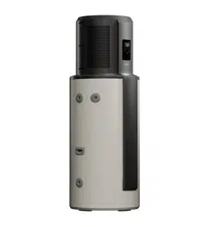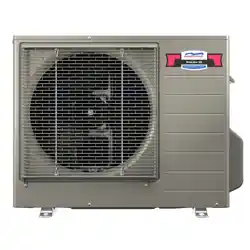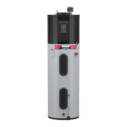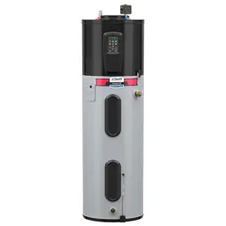
Heat Pump Water Heater
Operation and Installation Manual
Model
HP200M1-U1
HP250M1-U1
SAA-230239-EA
AS/NZS 2712
SMK41331
AS 3498 WMK26822
Please read this manual carefully prior to the
installation and use of this appliance.
The appearance of the water heater given in
this manual is for reference only.
This product must be installed outdoors.

2
Product safety statement:
Contents
1. Safety warnings ....................................................................................................... 4
2. Functioning principles of heat pump water heaters ..................................................... 8
3. Technical specification ............................................................................................. 9
4. Description of parts and components ...................................................................... 10
5. Transport and storage instructions .........................................................................12
6. Installation instructions ........................................................................................... 12
7. Commissioning checklist ......................................................................................... 19
8. Operating functions ............................................................................................... 20
9. Checking and maintenance ................................................................................... 25
10. Faults and protection .............................................................................................. 27
Dear users of Haier,
Thank you for choosing Haier products.
Please read this manual carefully and follow the operation and safety instruction to
ensure best installation and utilisation of the product.
1.
This appliance is not intended for use by persons with reduced physical,
sensory or mental capabilities, persons with a lack of experience and
knowledge, or children under the age of 8 years. Persons in this group must
be supervised while using the appliance by a person responsible for their
safety.
2.
Children should be supervised to ensure that they do not play with the
appliance.
3.
Installation must be carried out by qualified professionals. Do not
open the cover or panel unless qualified to undertake this work.
Contact Haier Customer Service if service or repair work is required.
4.
This appliance must be permanently connected to mains water supply
and continuous electrical supply.
3
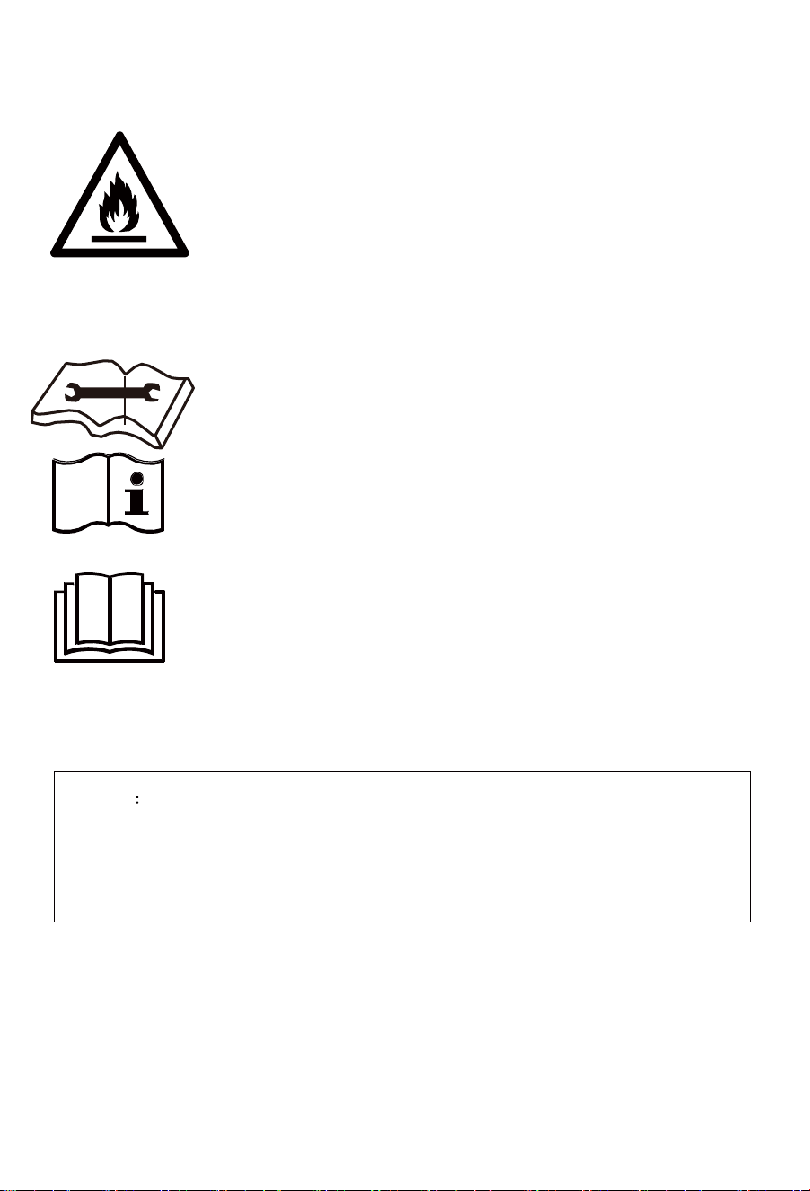
Warning Risk of damage to the environment
This heat pump contains R290 refrigerant. This refrigerant must not escape into
the atmosphere.
Refrigerant must be removed and disposed of by a qualified professional.
Warning: flammable hazard!
1. Please read the instructions carefully before
installation and use of this appliance.
2. Do not puncture or ignite this product.
3. The environment-friendly refrigerant R290 used in
this product is odorless.
4. This product must be installed outdoors.
5. This product cannot be discarded or scrapped without
correct retrieval of the refrigerant.
a. If necessary, please contact Haier Customer Service to
obtain the correct disposal method.
6. The product must not be stored in an area containing
an open flame such as an open fire, gas appliance or
electric heater.
7. Before the refrigeration system is repaired, the refrigerant
must be removed by a qualified professional.
8. Do not use any method to accelerate the defrosting
process or clean frosted components of the appliance.
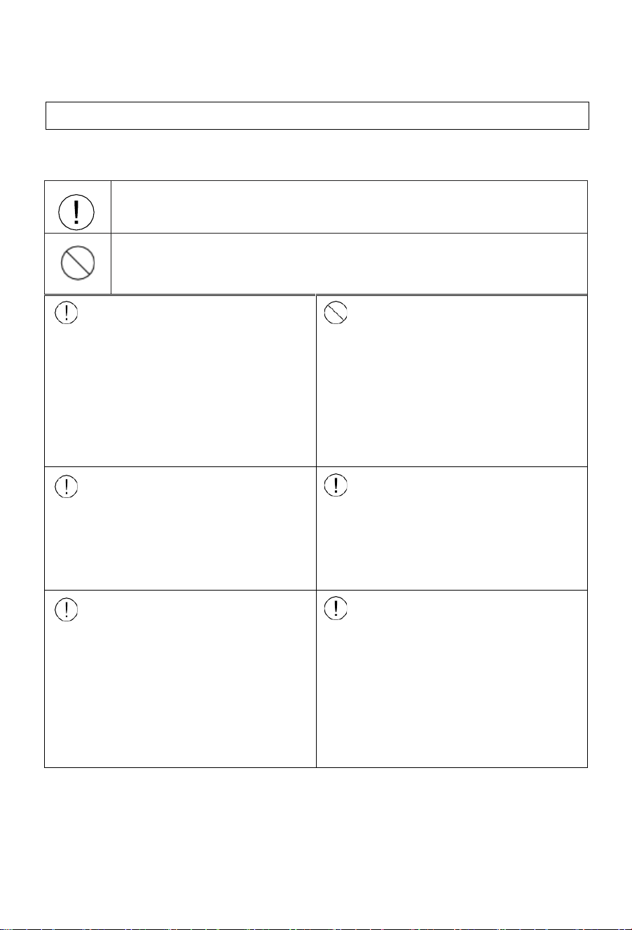
Safety warnings – To be followed at all times
4
Failure to follow these instructions may lead to serious malfunctions of the device
and danger to the user.
Instructions marked with this symbol must be followed. Failure to do so
may lead to product damage and harm to the user.
Information marked with this symbol are forbidden. Failure to follow
this instruction may lead to product damage and harm to the user.
The water heater shall be
installed in strict accordance
with local wiring regulations.
The power supply must have
a grounding line. Ensure an
effective ground connection.
Ground and neutral lines of
the power supply must not
be connected. The ground
line shall not be connected
to gas or water pipes,
lightning arresters or
telephone lines.
The water heater must be
installed in a location where
suitable water drainage is
possible.
The water heater must be
installed outside.
This appliance must be fitted
with the pressure temperature
relief valve (PTR valve)
supplied with the appliance.
The PTR valve must be fitted
directly to the appliance.
While bathing, children must
be under guidance of an adult.
Children must not play with
the appliance.
Interpretation of marks and symbols
Safety warnings – To be followed at all times
5
The outlet water temperature
of a water heater is typically
higher than the temperature
indicated on the display.
Ensure that contact to hot
water directly leaving the
appliance cannot occur.
This appliance must be
installed with an isolation
switch to the power supply.
This switch must ensure full
disconnection and be in
accordance with the wiring
rules.
Install the water heater in strict
accordance with these
installation instructions.
If the power cord is damaged,
it must be replaced by a
qualified professional.
Do not put hands or other
items into the air grid. This
may cause injury or damage
to the appliance.
Risk of damage to the
environment. This heat pump
contains the refrigerant R290.
The PTR valve drain must be
installed in a continuously
downward direction, be open
to the atmosphere, be free
from blockages, and the
potential to frost.
The PTR valve must be
operated every six months to
remove lime deposits, and to
ensure that it is free from
blockages.

Safety warnings – To be followed at all times
6
1.
Installation, service, or maintenance of this appliance must be carried out
by a qualified professional. Failure to adhere to this may result in damage
to the appliance or other property, or cause injury.
2.
Fit the appliance in accordance with this installation manual.
3.
Be sure to use only certified parts and accessories in the installation of this
appliance.
4.
Install the product on a base that can hold the filled weight of the
appliance.
5.
Electrical work must be performed in accordance with all local standards
and regulations, including AS/NZS3000, and the instructions in this
manual.
6.
This appliance must be connected to a dedicated electrical circuit.
7.
During installation, ensure that the ground wire is disconnected last.
8.
If a refrigerant leak occurs, ventilate the area immediately. The refrigerant
is flammable, so damage or injury is possible if it reaches an open flame.
9.
Be aware that the refrigerant contained in this appliance does not have an
odour.
10.
Do not accelerate the defrosting process or clean the evaporator when
frosted. Only a qualified person should clean the evaporator.
11.
Do not pierce or burn this appliance.
12.
This appliance must be installed outside and be well ventilated. A gas
leak in a poorly ventilated area could create an explosion risk.
13.
Prevent insects and small animals entering the appliance. This may cause
electrical shorts, malfunctions or fire.
14.
Only qualified personnel can handle, fill, purge and dispose of the
refrigerant in this appliance.
15.
If installed in a coastal or high sulfate gas region, corrosion will occur
shortening the appliance life.

Safety warnings – To be followed at all times
7
Loading and unloading requirements
1.
This appliance shall be carefully handled during transport loading and
unloading.
2.
Ensure that the appliance is not dropped, bumped, or rolled during
transportation as this could cause damage to the appliance,
potentially creating a refrigerant leak.
Transport requirements
1.
Local transport regulations should be consulted to determine the
maximum allowable appliance quantity or refrigerant (R290) volume
that can be transported at any one time.
Storage requirements
1.
As this appliance contains a flammable refrigerant R290, its storage
must be in accordance with local regulations.
2.
The storage should ensure that there is no potential for damage to the
appliance. Any damage could result in a refrigerant leak.
Scrapping and recovery requirements
1.
Scrapping must only be carried out by a qualified professional. This
professional must safely recover the appliance’s refrigerant before the
appliance is scrapped. Contact Haier Customer Service to correctly
dispose of this appliance.
Technical specifications
8
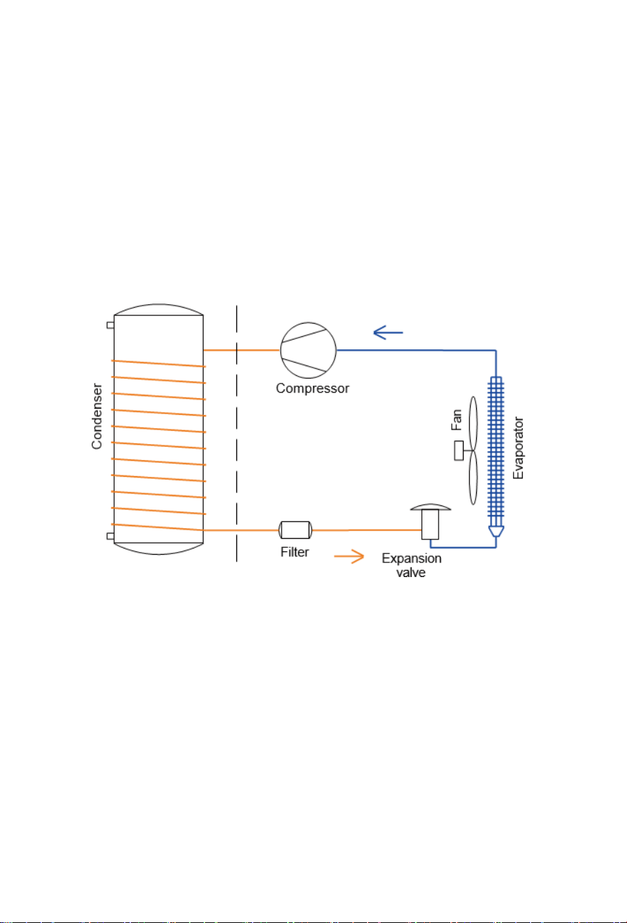
Functioning principles of heat pump water heaters
Air source heat pump water heaters mainly consist of a compressor, an
expansion valve, a filter, an evaporator, a condenser, and a fan. Powered
by electricity, the compressor absorbs low-temperature and low-pressure
refrigerant gas from the evaporator. It compresses the gas into high-
temperature and high-pressure gas, which is passed through the condenser
to transfer heat to the water. The condensed refrigerant is then throttled and
depressurized by the expansion valve. It then absorbs heat from the
surrounding air via the evaporator.
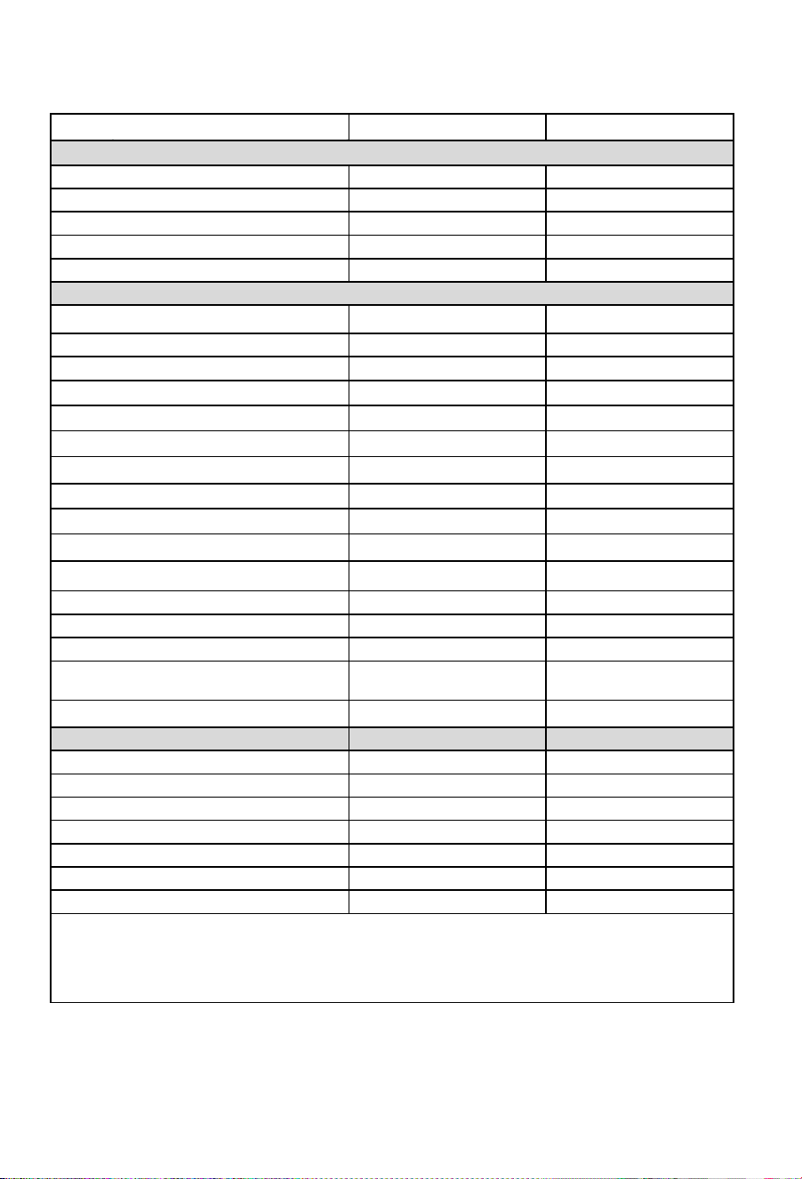
Technical specifications
9
Model
HP200M1-
U1
HP250M1-
U1
Tank
Total water
capacity
195L
246L
Rated
voltage/
frequency
220-
240V/50Hz
220-
240V/50Hz
Tank
max pressure
700kPa
700kPa
Corrosion
protection
Magnesium
rod
Magnesium
rod
Waterproof
grade
IPX4
IPX4
Performance
(20°C/15°C
Ambient
air
temperature,
15°C
-55°C
water
temperature)
COP*@ 20°C/15°C
4.49
4.48
Power
input
of
electric
element
1500W
1500W
Rated
power
input of heat
pump
430W
430W
Maximum
power
input
of
heat
pump
750W
750W
Maximum
power
input
2250W
2250W
Average
heating
capacity
by
heat
pump
2000W
2000W
Heating
water
capacity
42L / h
42L / h
Heating
up
time
(15
℃
-55
℃
)
4.6h
5.8h
Default
temperature
setting
60°C
60°C
Temperature
setting
range-
with
heater
35°C – 75°C
35°C – 75°C
Max temperature of the heat pump only
65°C
65°C
Max
working
pressure
of refrigerant
1.0/3.3MPa
1.0/3.3MPa
Refrigerant
type
/
weight
R290/0.34kg
R290/0.34kg
Sound
pressure
level
*@
1m
43dB(A)
43dB(A)
Ambient
temperature for heat pump
and element
-7~45°C
-7~45°C
Ambient
temperature
of heat
pump
-7~45°C
-7~45°C
Dimension
and
connections
Water
inlet
and
outlet
connection
Rp
¾”
Rp
¾”
TPR
valve
connection
Rp
¾”
Rp
¾”
Drain
&
Water
inlet
connection
Rp
¾”
Rp
¾”
Product
Dimensions
600*630*1658mm
600*630*1951mm
Packing
dimension
with
pallet
736*695*1940mm
736*695*2250mm
Net/Gross
weight
91/116kg
106/128kg
Filled
weight
of
the
appliance
286kg
352kg
*
The COP was measured under test conditions with an ambient air temperature of 20˚C/15˚C
(Dry Bulb/Wet Bulb) and heating of the water from 15˚C to 55˚C during water heater operation.
*
The noise level was measured at 1 m from the water heater during a Noise Test conducted to
Standard GB/T 23137 in a hemi-anechoic chamber within a laboratory.
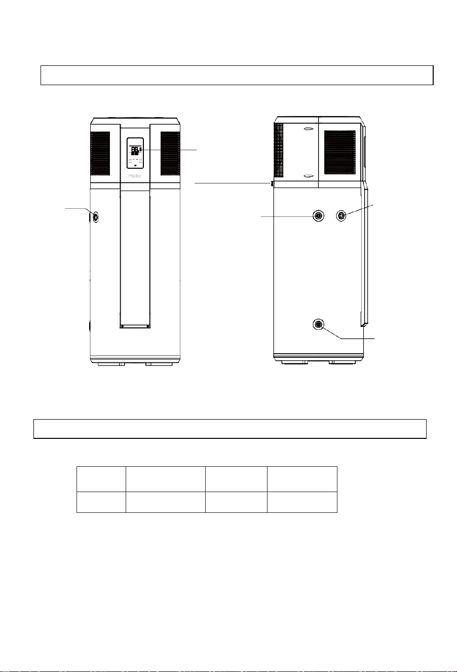
Description of parts and components
10
Carton contents
Display
PTR valve
connection
Condensation drain
Hot water
outlet
PTR valve
connection
Cold water
Inlet
Part
name
Heat pump
water heater
TPR
valve
Instruction
manual
Quantity
1
1
1
Heat pump layout
Description of parts and components
11
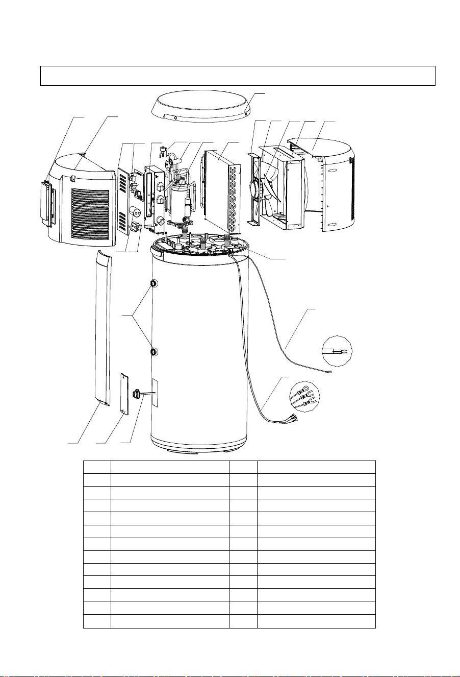
Exploded view of the heat pump
S/N Description
1 Display panel & Cover
2
Front shell
3 Electrical box cover
4 Control panel
5 Electrical box
6
Electronic expansion valve
7 Four-way valve
8 Compressor
9 Evaporator
10 Top cover
11 Support
13
14
Diversion air duct
Fan blade
S/N Description
15
Rear shell
16 Compressor capacitanc
e
17
Thermal cut-out
18 Decorative cover
19 Waterproof cover
20 Heating element
21 Sensor pocket
22 Magnesium anode
2
1
3
4
5
16
●
17
6
7
8
9
12
13
11
14
15
10
18 19
20
23
21
24
22
12 DC motor
23
Communication cable
24
Power cable

Installation instructions
12
Selection of installation site
1.
During transport or storage, the heat pump water heater should
remain in undamaged packaging to prevent damage to the appliance.
2.
During long periods of transport or storage, the heat pump water
heater must be in an upright position.
3.
For short distance transportation (under one hour), this product may
be laid down within 1 hour as per indication on packaging. If laid
down, the appliance must be at an upright position for 4 hours prior
to its initial startup.
1.
Ensure the install location is stable and level, and that air can flow in and out freely,
and will be minimally affected by wind.
2.
The base or surface can support the filled weight of the appliance and the
condensate water can be drained freely.
3.
If installed on a base, ensure that this base is level to allow correct drainage
via the condensate drain at the rear of the appliance.
4.
The location or position of the appliance will not create nuisance
noise for the homeowners or neighbors, especially through proximity
to bedrooms.
5.
Ensure that the location allows condensate and PTR valves to be
drained into an area that will not cause damage to the surrounding
area.
6.
There is sufficient space left for installation and maintenance of the appliance.
7.
There is no strong electromagnetic interference around the appliance
that may affect its control functions.
8.
There are no corrosive vapors such as aerosol sprays, stain removers or
household chemicals near the install location. These vapors may corrode the
appliance and its fittings.
9.
Considerations have been made to prevent water pipes from freezing in colder
regions.
Transporting the appliance
Installation instructions
13
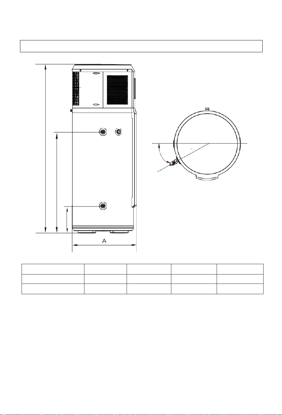
30°
PTR valve
unit:
mm
Model
A
B
C
D
HP200M1-U1
630
267
979
1658
HP250M1-U1
630
267
1272
1951
Installation dimensions
D
C
B
Installation instructions
14
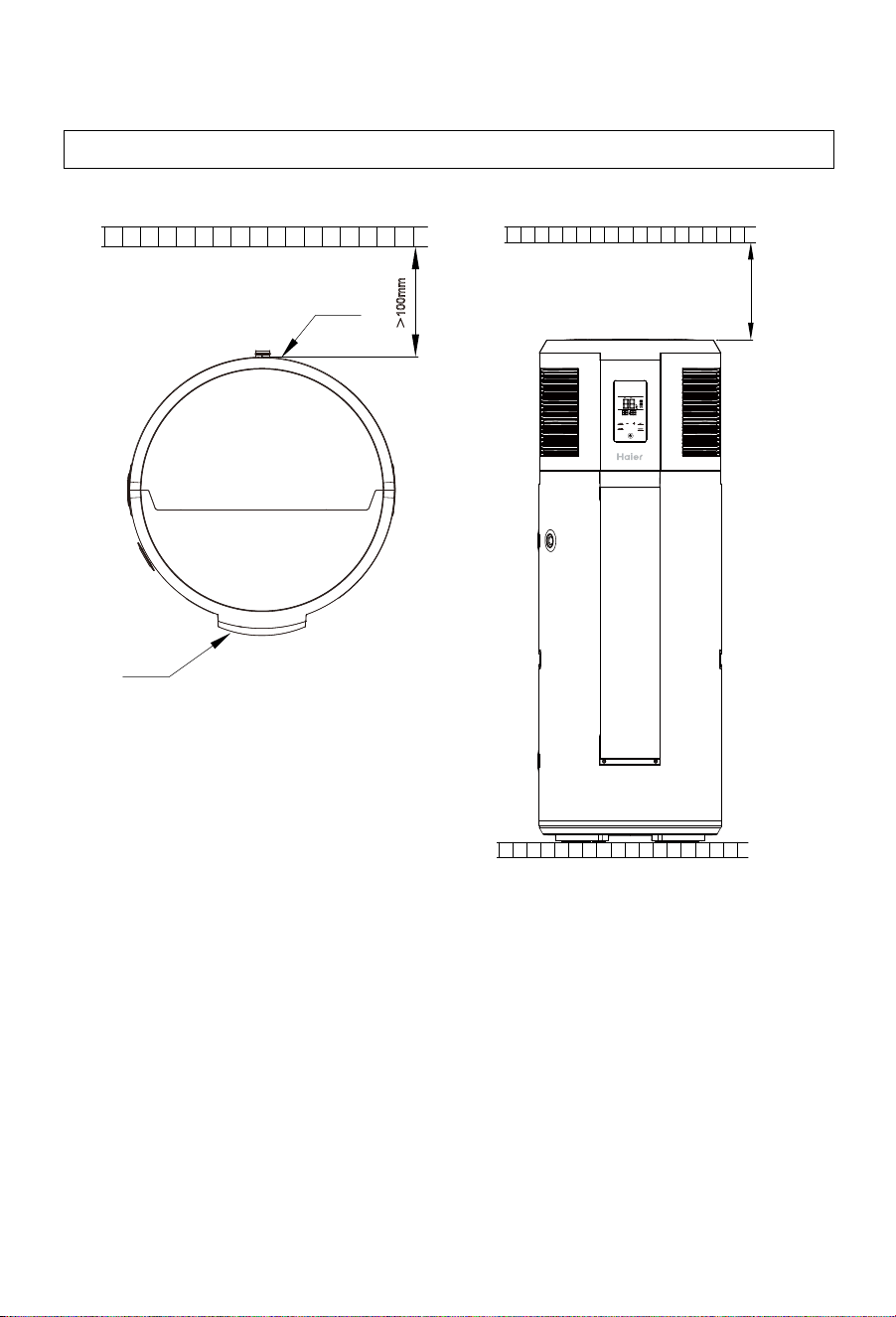
Installation clearances
Note: This appliance must be installed in a location where it can be
quickly and easily drained and moved to a location with 1000mm
clearance above the appliance. This is so the anode to be removed for
checking and replacing during the 5 yearly service
.
>300mm
>100mm
Air outlet
Display

Installation instructions
15
WARNING — FOR CONTINUED SAFETY OF THIS APPLIANCE IT
MUST BE INSTALLED, OPERATED AND MAINTAINED IN
ACCORDANCE WITH THE MANUFACTURER’S INSTRUCTUCTIONS.
WARNING — THIS APPLIANCE MAY DELIVER WATER AT HIGH
TEMPERATURES. REFER TO THE PLUMBING CODE OF
AUSTRALIA (PCA), AND ALL LOCAL REGLATIONS ON ADDITIONAL
DELIVERY TEMPERATURE CONTROL MUST BE FOLLOWED.
1.
The water heater must be installed:
a.
by licensed trades people.
b.
in accordance with all local codes and regulations and
standards including AS/NZS3500.4, AS/NZS 3000, and the
Plumbing Code of Australia (PCA).
2.
The inlet water pressure of water supply must be between 100kPa –
500kPa.
3.
Inlet water connections: An isolating and non-return valve must be
installed on the inlet to the appliance. If the supply pressure could
exceed 500kPa, a pressure limiting valve must be installed on the
cold-water inlet. If a cold water expansion control valve (ECV) is
required by local regulations, a valve of a maximum of 600kPa can
be fitted. The correctly sized pressure limiting valve should also be
fitted as per the ECV manufacturers specifications.
If no ECV is fitted, a pressure limiting valve of a maximum of 500kPa
should be fitted.
4.
The cold-water inlet to the appliance must have a line filter, non-
return valve and isolating valve fitted. Combination valves of these
functions are also suitable.
5.
Outlet water connections: A thermostatic mixing or tempering valve
must be used when hot water is supplied to fixtures used for sanitary
use (i.e. bathrooms) according to AS/NZS 3500.4 requirements.
6.
For ease of assembly and disassembly of the appliance, it is
recommended that mechanical joints are used to connect to the
water heater.
Plumbing installation

Installation instructions
16
7.
The water inlet and outlet pipes must be fitted to as per the labels at
the hot and cold-water connections.
8.
To avoid damage to the appliance, the inlet water temperature should
remain between 10-40°C.
9.
Before filling the tank, make sure that the cold-water inlet and hot-
water outlet of the appliance are open, along with the farthest hot
water fixture are opened. The appliance will be correctly filled once
water flows continuously from this fixture without air bubbles.
Venting through the PTR could cause premature failure of the
valve.
10.
If there is a risk of freezing, hot and cold water pipes connected to
the appliance must be insulated with 20mm insulation. Failure to
adhere to this may result in a voided warranty if damage due to
freezing occurs.
11.
In accordance with safety rules, a PTR valve (700kPa, 99°C, Rp3/4”)
must be installed directly into the PTR valve connection on the
appliance. Never block the outlet of the safety valve or its drain line
for any reason.
Plumbing installation continued

Installation instructions
17
CAUTION: In order to avoid inadvertent resetting of the thermal cut-out, this
appliance must not be supplied through an external switching device, such as
a timer, or connected to a circuit that is regularly switched on and off by the
utility (off-peak electrical line).
Electrical Safety Requirements
1.
The installation, service or repair of the electrical components of this
appliance must be completed:
a.
by licensed trades people.
b.
in accordance with all local codes and regulations and
standards AS/NZS 3000.
2.
The surrounding conditions (ambient temperature, direct sunlight and
rainwater) shall be considered during electrical wiring, with effective
protective measures taken to suit the environment.
3.
Materials that are certified to local standards must be used in the
installation of this appliance.
4.
The appliance must be reliably earthed.
5.
This appliance must be connected to a dedicated circuit. This circuit
must be fitted with a circuit breaker that is no greater than 20 A. It is
recommended that a residual current device (RCD) is also fitted.
6.
The circuit to the appliance should be a minimum of 2.5mm² 2-core
and earth.
Electrical installation
Installation instructions
18
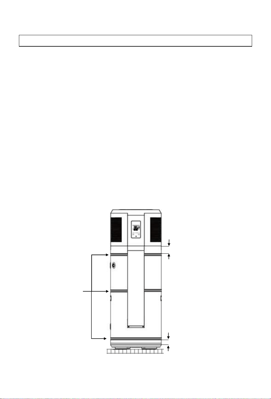
FOR NEW ZEALAND INSTALLS ONLY
The Plumbing and Drainage standard (AS/NZS 3500.4) requires all
storage water heaters in New Zealand to be installed with seismic
restraints to avoid damage or personal injury if a seismic event should
occur.
To meet this requirement this appliance should be fitted with three
stainless steel straps, 25mm wide x 1mm thick.
These straps should be fitted as per the following instructions:
Top strap: Under the front cover, and no more than 100mm from the
top the painted cylinder section of the appliance
Middle strap: Under the front cover, at the center of the painted
cylinder section of the appliance
Bottom strap: Below the front cover, and no more than 100mm from
the bottom the painted cylinder section of the appliance.
Seismic straps
Seismic strapping
<100mm
<100mm
Installation instructions
19
Installers should check that the following tasks have been completed correctly
during the commissioning of this appliance.
o
The electrical connection is correctly hard wired.
o
Water connections have been fitted correctly and are leak free after the
appliance is filled.
o
The control panel is operational.
o
The supplied PTR valve has been correctly fitted to the appliance, and
releases water when the lever is pulled.
o
All hot water lines are correctly insulated.
Commissioning checklist
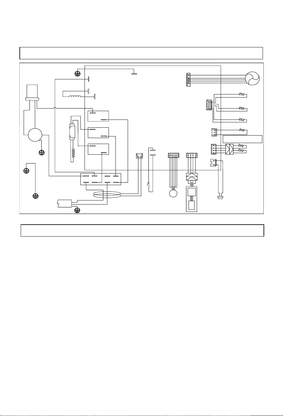
Wiring diagram
R
S
C
K3
Black
FAN
t
●
t
t
CN1
K1
K2
L
(L)
(
N
)
L
︳
IN
N
︳
IN
N
Leakage
protection coil
GND
Capacitor
White
Compressor
Electric
heating
element
Blue
Brown
Blue
Over-tempeature
thermostart
Four-way
valve
White
Discharge temperature
sensor
Defrost temperature
sensor
Ambient temperature
sensor
Suction temperature
sensor
CN12
CN6
C
N19
CN
1
7
t
CN15
Water tank temperature
sensor ( upper)
t
t
CN14
Water tank temperature
sensor
(
lower
)
High pr
essure
switch
Dis
p
lay pane
l
WIF
I
EXV
Expan
sion valve
CN7/8
CN24
CN5
Blue
CN11
Valley valve electric signal
Electric
wire
MAIN BOARD
CN
16
L
︳
IN
CN13
CN10
Red
Brown
Brown
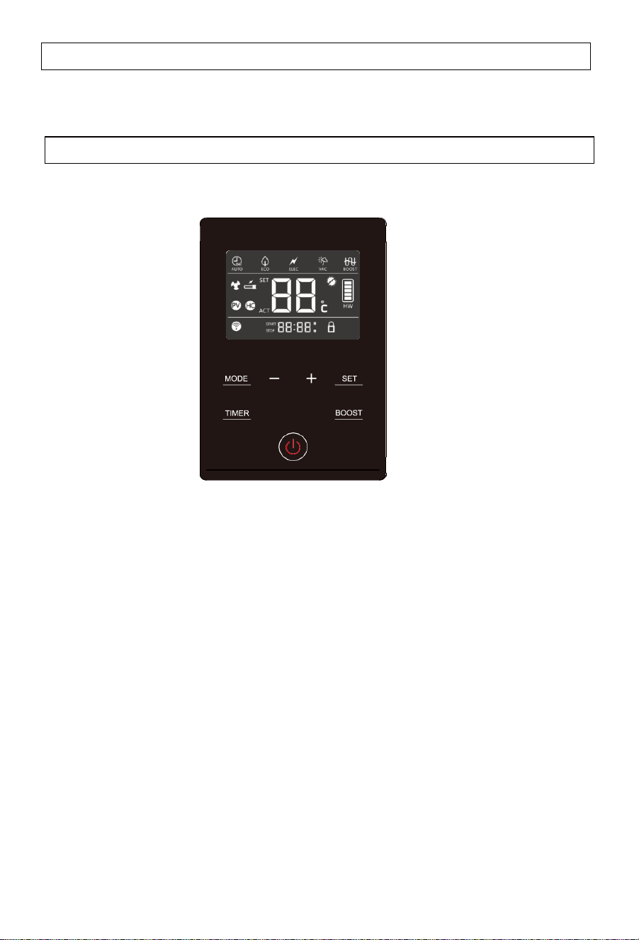
Description of the icons
20
Display
Operating functions
Functions & Protections
A.
Electrical
leakage
protection
This appliance features an electricity leakage protection function.
B.
Compressor protection
When switched on, the appliance will take approximately 3 minutes to start the
compressor for heat pump heating.
C.
Automatic defrosting function
The defrosting mode is automatically activated if the outdoor temperature is
low and the compressor has run for some time.
D.
Overload protection
The working load of the compressor will be high in warm ambient air temperatures.
To meet hot water requirements and to lengthen appliance life, this product
automatically adjusts the fan speed to ensure reliable operation of the
compressor.
E.
Anti-freezing function
The heat pump maintains a minimum temperature to avoid damage to the
appliance caused by freezing.
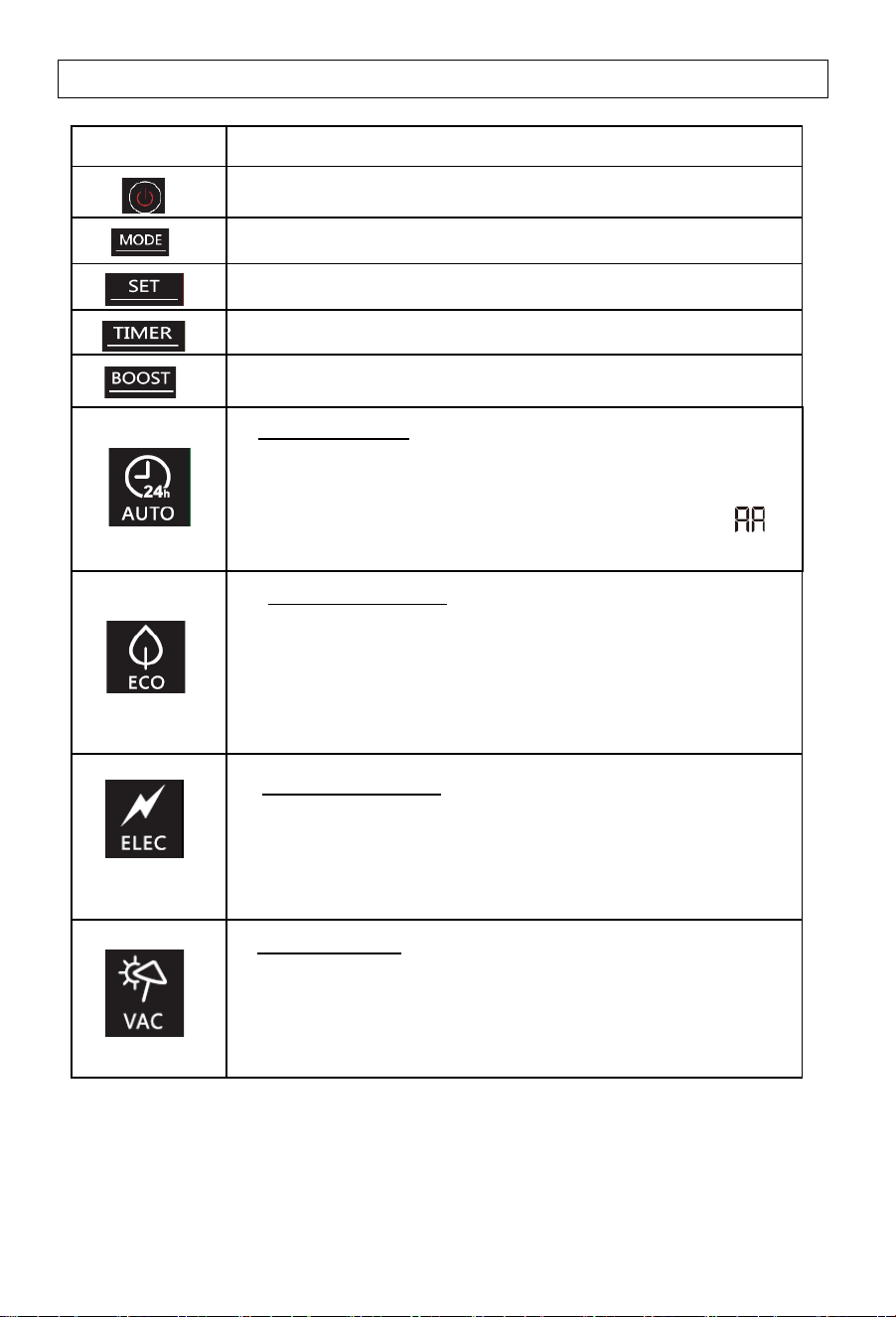
Description of the icons
21
Symbol
Description
Power ON/OFF switch
Working mode selection
Confirming the selection
Timer adjustment
Boost mode. Heat pump and backup element heat
simultaneously for a faster recovery time.
Auto mode
- Optimised management of the heat pump and backup element
for guaranteed comfort
- The compressor maximum continuous working time( )
can be adjusted in the installer settings.
ECO (off-peak) mode
- Prioritizes heat pump heating via two
methods
1 - User entered timer settings
2 - Communication from power companies.
Electric heating mode
- In this mode, the backup element is used as the only
heat source.
- This function ensures hot water supply when the heat pump
is not working properly.
Vacation mode
- Maintains a minimum temperature to prevent freezing, then
heats to the set temperature for the owners return. Set by
number of days by the owner.
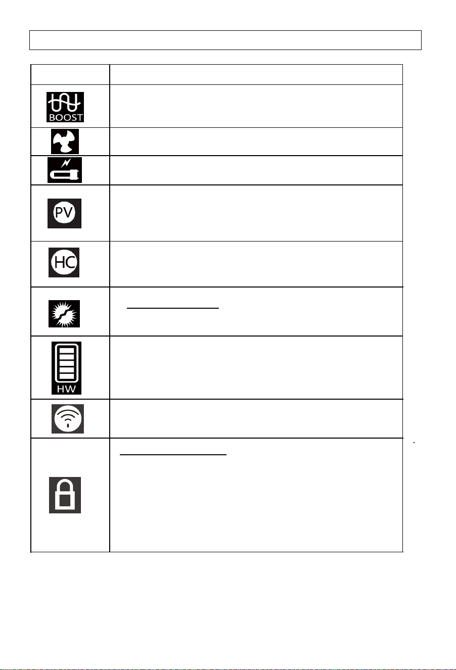
Description of the icons
22
Symbol
Description
Boost mode. Heat pump and backup element
are activated at the same time (only in AUTO mode).
Heat pump working icon.
Auxiliary electrical heater working icon.
legionella
Note: Under certain conditions, ECO mode may result in shortages of hot water if
the ambient air temperature is low.
When the PV function is turned on, the setting temperature will
be automatically adjusted to 65
°C,
when the PV effective signal
is received, the heat pump and electric heating will be turned on
at the same time.
Hot water volume display.
Time of peak/off-peak hours. In Time of peak/off-peak hours
mode, the symbol corresponding to the mode is displayed.
When receiving the signal, "HC" lights up.
Anti-
- Anti-legionella function will be activated every 7 days to
heat the tank to 65°C automatically .
WIFI signal icon.
Lock screen display icon
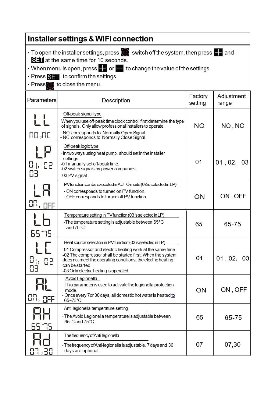
1. Enter: In the power-on state, press and hold TIMER+BOOST
(combination key) for 6s at the same time, the lock sign will be
on, and the screen lock mode will be turned on.
2. After the screen lock mode is turned on, the device will not
respond when the user touches any key.
3. Exit: press and hold TIMER+BOOST (combination key) for 6s
at the same time, the lock sign is closed, and the screen lock
mode is exited.
Operating functions
23
Operating functions
24
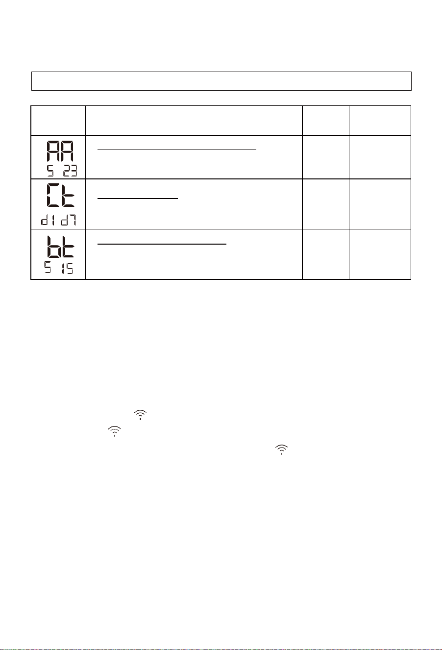
Parameters
Description
Factory
setting
Adjustment
range
-
Compressor maximum continuous working time
- If the maximum continuous working time of the compressor
more than Set Time, start auxiliary power.
10h
5-15h
-
Set the day of the week
- Set the day of the week, d1 to d7 for Monday to Sunday, and
remember the day of the week.
/
d1-d7
-
Reheat differential temperature setting
- Reheating will start in the 200L at 10°C below the set
temperature. The 250L will start at 9°C below the set
temperature. The adjustment range is 5-15°C.
9/10
5-15
WIFI connection
Your appliance can be connected to your home wireless network and operated
remotely using the app.
Getting started:
1. Ensure your home Wi-Fi network is turned on.
2. Press and hold "-" to enter the distribution network status. At this
time, the WIFI icon ( ) will flash. If the connection is successful
the WIFI icon ( ) will always be on.
If the connection is not successful, the WIFI icon ( ) will always be flashing.
3. It may take up to 10 minutes to connect your appliance.
On your mobile device:
1. Download the app from www.fisherpaykel.com/connect
2. Register and create an account.
3. Add your appliance and set up the Wi-Fi connection.
Installer settings & WIFI connection
25
Installation and maintenance of the appliance must be undertaken by a qualified
professional.
Before working on the appliance, shut down the machine and isolate the power
supply at the switch.
Do not touch with wet hands.
Maintenance operations are important to guarantee optimal
performance
and extend the life of the appliance.
-
The evaporator fins are sharp and are a potential injury risk.
-Avoid damaging the evaporator fins as this can affect the performance of the
appliance.
Checking and maintenance
Checking the PTR valve
-
Operate the PTR valve at least once
every six months to ensure it is functioning
correctly. If the valve fails to release water when the lever is activated, check
for blockages. If none exist, call Haier Customer Care or a qualified
professional to resolve the issue.
Checking the pipework
-
Check the watertightness of the water connections and piping.
Cleaning the fan
-
The fan should be checked for dust annually. If cleaning is required call Haier Customer
Service or a qualified professional.
-
Checking and cleaning the evaporator must be completed by a qualified professional.
-
It is recommended that the evaporator is cleaned every two years.
Clean the evaporator with a soft brush and water if required. Do not use cleaners on the
evaporator fins.
Checking the condensate drain
-
Check the condensate drain for blockages as they have the potential to flood
the appliance.
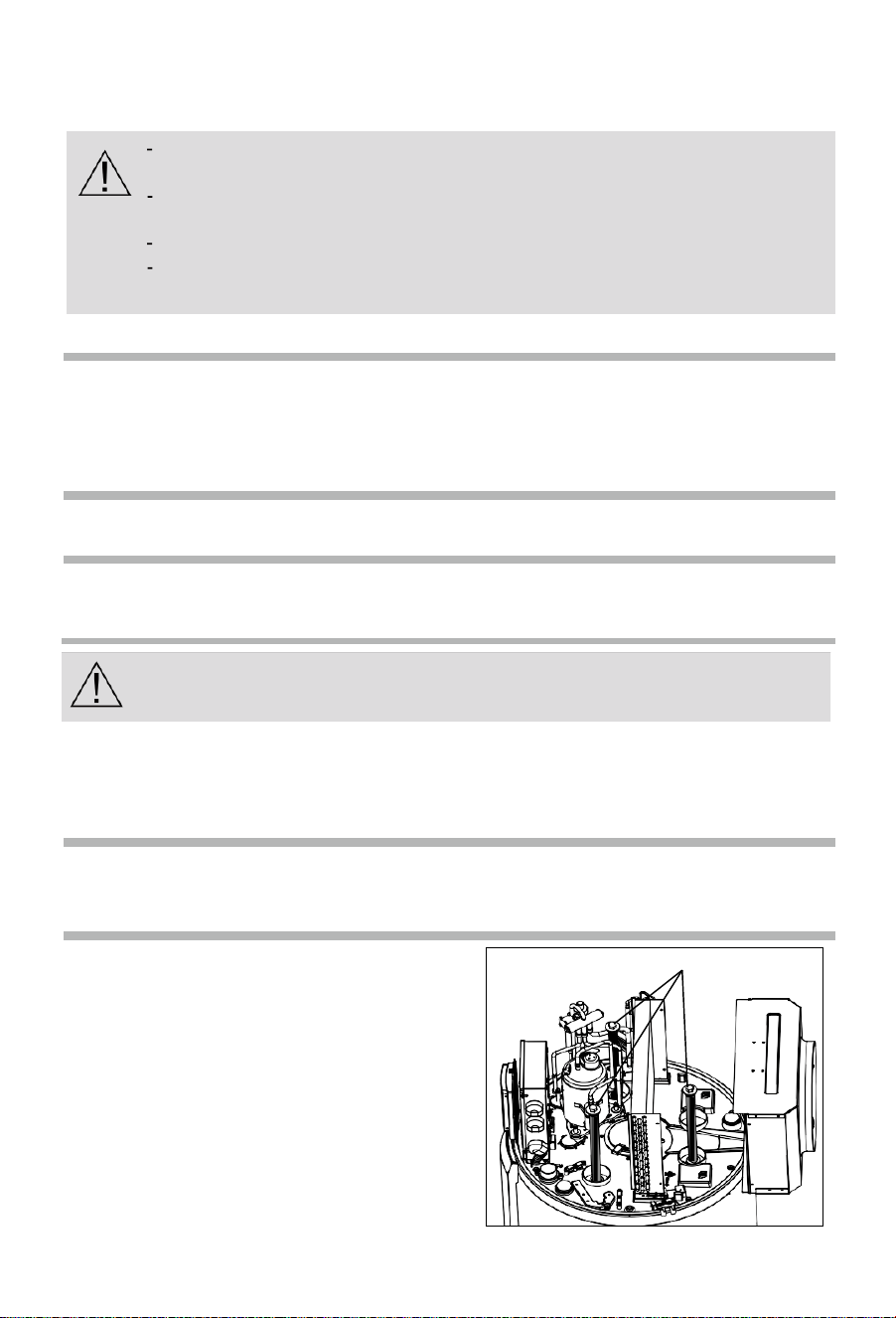
Checking the anode
-
Checking and replacing the anode must be
carried out by a qualified professional.
-
To avoid irreversible corrosion of the cylinder,
it is recommended to check the anode every
five years, and replaced if required.
Magnesium anode

Faults and protection
26
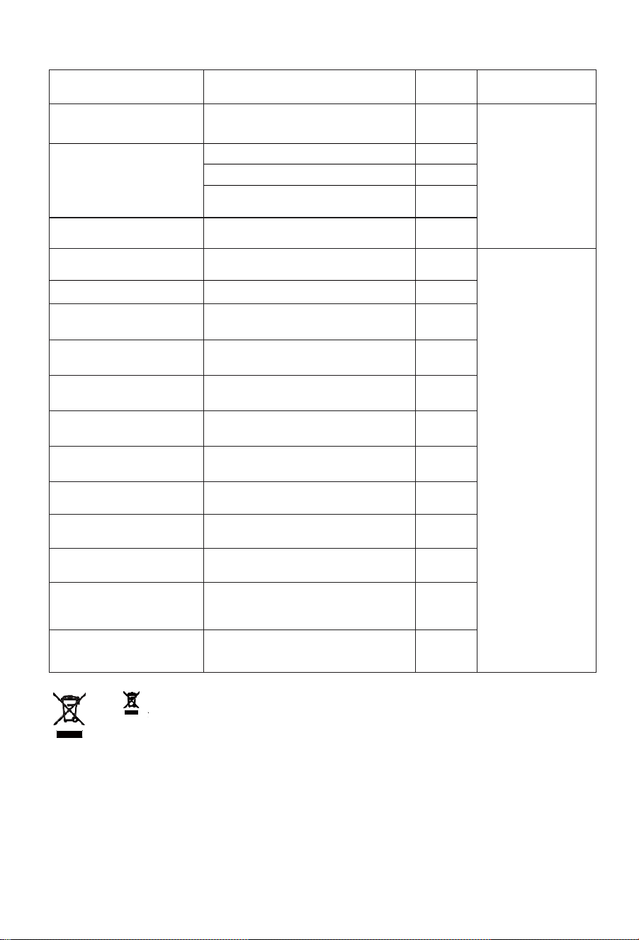
Water Properties
Acceptable Levels
pH
Min 6.5 to Max 8 .5
Water Quality
A breach of this condition may void the warranty in the event of damage caused
by water quality exceeding these characteristics.
Water supply from an unfiltered water source that may be highly conductive or have a
high mineral content may void the system warranty.
The following characteristics should not be exceeded in order for the warranty to be
conditions not to be breached.
Total hardness
200 mg/litre or ppm
Chloride
250 mg/litre or ppm
Sodium
150 mg/litre or ppm
Electrical conductivity
850 μS/cm
10 mg/litre or ppm
Magnesium
600 mg/litre or ppm
Total Dissolved Solids (TDS)
Faults and protection
27
Fault
type
Action
Digital
indication
Release
Communication fault
Communication failure between Wi-Fi
module and control board
F0
Please call Haier
Customer Service to
resolve the issue.
Compressor protection
Operating temperature protection
F2
Air exhaust temperature protection
F3
Evaporation high temperature
protection
F5
Compressor over-current
protection
Over-current protection
F6
Electricity
leakage
alarming
The system will automatically cut off
power supply if any line fault occurs
E1
Please call Haier
Customer Service to
resolve the issue.
Over temperature alarming
The actual water temperature≥85℃
E2
Fault of the inner
temperature sensor
If short circuit or circuit break occurs
to the sensor
E3
Fault of the ambient
temperature sensor
If short circuit or circuit break occurs
to the sensor
E4
Fault of the evaporation
temperature sensor
If short circuit or circuit break occurs
to the sensor
E5
Fault of the air exhaust
temperature sensor
If short circuit or circuit break occurs
to the sensor
E6
Fault of the air intake
temperature sensor
If short circuit or circuit break occurs
to the sensor
ED
Communication fault
Communication of main control panel
and display panel is abnormal
E7
Pressure switch protection
Action of the pressure switch at the
exhaust outlet
E8
Ambient temperature
protection
Ambient or outdoor temperature
<-7℃ or>45℃
E9
Fault of the Off-peak power
switching signal
If not received the Off-peak signal
when selecting switch signals by
power companies
EF
Fault of the fan
Fan blade is stuck or fan and control
panel communication failure
L7
The symbol on the product or on its packaging indicates that this product is not
to be treated as regular household waste. It must be taken to a recycling
collection point for electronic equipment. By properly disposing of this product,
you are contributing to the preservation of the environment and the wellbeing of
your fellow citizens. Improper disposal is hazardous to health and environment. You
can obtain further information on how to dispose of this product correctly by calling Haier
Customer Service.

Haier Appliances
Australia 1300 729 948 | haier.com.au
New Zealand 0800 424 372 | haier.co.nz
Fisher & Paykel Australia Pty Ltd, Level 1, 1 Eden Park Drive, Macquarie Park, NSW 2113.
Phone Customer Care: 1300 729 948 Email: customer.care@haier.com.au
Fisher & Paykel Appliances Ltd, 78 Springs Road, East Tamaki, Auckland 2013.
Phone Customer Care: 0800 424 372. Email: customer.care@haier.co.nz
0040511380
20230228
V*****