Please read this manual carefully prior to the
installation and use of this appliance.
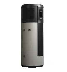
The appearance of the water heater given in
this manual is for reference only.
This product must be installed outdoors.
Heat Pump Water Heater
Operation and Installation Manual
Model
HP330M1U1
SAA-230239-EA
AS/NZS 2712
SMK41331
AS 3498 WMK26822

2
Product safety statement:
1. This appliance is not intended for use by persons with reduced
physical, sensory or mental capabilities, persons with a lack of
experience and knowledge, or children under the age of 8 years.
Persons in this group must be supervised while using the appliance
by a person responsible for their safety.
2.
Children should be supervised to ensure that they do not play with
the appliance.
3. Installation must be carried out by qualified professionals. Do not
open the cover or panel unless qualified to undertake this work.
Contact Haier Customer Service if service or repair work is required.
4. This appliance must be permanently connected to mains water
supply and continuous electrical supply.
Contents
1. Safety warnings .............................. .................................................................. 4
2. Functioning principles of heat pump water heaters .............................................13
3. Technical specification ......................................................................................14
4. Descriptionof parts and components ................................................................. 15
5. Transport and storage instructions .................................................................... 17
6. Installation instructions ..................................................................................... 18
7. Commissioning checklist .................................................................................. 27
8. Operating functions .......................................................................................... 28
9. Checking and maintenance .............................................................................. 40
10. Faults and protection ........................................................................................ 42
Dear users of Haier,
Thank you for choosing Haier products.
Please read this manual carefully and follow the operation and safety
instruction to ensure best installation and utilisation of the product.
3
Warning: Risk of damage to the environment
This heat pump contains R290 refrigerant.This refrigerant must not escape
into the atmosphere.
Refrigerant must be removed and disposed of by aqualified professional.
The valve or drain valve outlet pipe must not be sealed or blocked.
If the hot water system is not used for two weeks or more, a quantity of highly
flammable hydrogen gas may accumulate in the water heater. To dissipate
this gas safely, it is recommended that a hot tap be turned on for several
minutes or until discharge of gas ceases. Use a sink, basin, or bath outlet,
but not a dishwasher, clothes washer, or other appliance. During this
procedure, there must be no smoking, open flame, or any electrical appliance
operating nearby. If hydrogen is discharged through the tap, it will probably
make an unusual sound similar to air escaping.
Warning: flammable hazard!
1. Please read the instructions carefully before
installation and use of this appliance.
2. Do not puncture or ignite this product.
3. The environment-friendly refrigerant R290 used in
this product is odorless.
4. This product must be installed outdoors.
5. This product cannot be discarded or scrapped without
correct retrieval of the refrigerant.
a. If necessary, please contact Haier Customer Service to
obtain the correct disposal method.
6. The product must not be stored in an area containing
an open flame such as an open fire, gas appliance or
electric heater.
7. Before the refrigeration system is repaired, the
refrigerant must be removed by a qualified
professional.
8. Do not use any method to accelerate the defrosting
process or clean frosted components of the appliance.

Safety warnings – To be followed at all times
Servicing and Decommissioning Warnings
Please follow this manual for installation and operation to avoid excessive
vibration or pulsation to refrigerating piping.
Workplace safety procedures must be followed to minimise the risk
caused by flammable refrigerant.
All maintenance staff and others working in the surrounding area shall be
instructed on the nature of work being carried out. Work in confined
spaces shall be avoided.
The area shall be checked with an appropriate refrigerant detector prior to
and during work, to ensure the technician is aware of potentially toxic or
flammable atmospheres. Ensure that the leak detection equipment being
used is suitable for applicable refrigerants, i.e. non-sparking, adequately
sealed or intrinsically safe.
If any brazing is required for repair of the applaince, appropriate fire
extinguishing equipment shall be available to hand. Have a dry powder or
CO2 fire extinguisher close by.
No person carrying out work on the refrigerant system must use any
sources of ignition in a manner that create a fire or explosion risk.
All possible ignition sources, including cigarette smoking, must be kept
sufficiently far away from the site of installation, repairing, removing and
disposal, during which refrigerant can possibly be released to the
surrounding space.
Prior to work taking place, the area around the equipment is to be
surveyed to make sure that there are no flammable hazards or ignition
risks. “No Smoking” signs displayed.
Ensure that the area is adequately ventilated before disconnecting the
refrigerant system or conducting any brazing. This must be continued
while work is carried out.
The ventilation should safely disperse any released refrigerant and
preferably expel it externally into the atmosphere.
When replacing electrical components, ensure that they are the correctly
specified parts supplied by Haier / Fisher & Paykel.
At all times the manufacturer’s maintenance and service guidelines shall
be followed. If in doubt, consult the manufacturer’s technical department
for assistance.
Repair and maintenance to electrical components shall include initial
safety checks and component inspection procedures.
If a fault exists that could compromise safety, then disconnect the
electricity supply until the fault is satisfactorily.
4

Safety warnings – To be followed at all times
5
Initial safety checks shall include:
that capacitors are discharged: this shall be done in a safe
manner to avoid possibility of sparking.
that no live electrical components and wiring are exposed while
charging, recovering or purging the system.
that there is continuity of earth bonding.
Sealed electrical components must not be repaired.
Under no circumstances shall potential ignition sources be used in the
searching for or detection of refrigerant leaks. A halide torch (or any
other detector using a naked flame) shall not be used.
Electronic leak detectors may be used to detect refrigerant leaks but, in
the case of flammable refrigerants, their sensitivity can be inadequate, or
can need re-calibration.
Ensure that the detector is not a potential source of ignition and is
suitable for the refrigerant used. Leak detection equipment shall be set at
a percentage of the refrigerant’s LFL, and shall be calibrated to the
refrigerant employed, and the appropriate percentage of gas (25%
maximum) is confirmed.
Leak detection fluids are also suitable for use with most refrigerants but
the use of detergents containing chlorine must be avoided as the chlorine
can react with the refrigerant and corrode the copper pipework.
If a leak is suspected, all naked flames shall be extinguished.
If a refrigerant leak is found which requires brazing, all refrigerant must be
recovered from the system, or isolated by means of shut off valves.
Removal of refrigerant shall be according to Clause 60335-2-40 DD.8.
When breaking into the refrigerant circuit to make repairs – or for any
other purpose – conventional procedures used. However, for flammable
refrigerants it is important that best practice is followed since flammability
is a consideration. The following procedure adhered to:
safely remove refrigerant following local and national regulations.
purge the circuit with inert gas evacuate.
continuously flush with inert gas when using flame to open circuit.
open the circuit.
This process repeated until no refrigerant is within the system
The system vented down to atmospheric pressure to enable work
to take place.
Ensure that the outlet of the vacuum pump is not close to any
potential ignition sources and that ventilation is available.

Safety warnings – To be followed at all times
6
Servicing and Decommissioning Warnings
In addition to conventional charging procedures, the following requirements
shall be followed.
Before attempting the procedure, ensure that:
Ensure that contamination of different refrigerants does not occur
when using charging equipment. Hoses or lines shall be as short as
possible to minimise the amount of refrigerant contained in them.
Cylinders shall be kept in an appropriate position according to the
instructions.
Ensure that the refrigerating system is earthed prior to charging the
system with refrigerant.
Label the system when charging is complete (if not already labelled).
Extreme care shall be taken not to overfill the refrigerating system.
Prior to recharging the system, it shall be pressure-tested with the
appropriate purging gas.
Before carrying out this procedure, it is essential that the technician
is completely familiar with the equipment and all its detail. It is
recommended good practice that all refrigerants are recovered
safely.
Prior to the task being carried out, an oil and refrigerant sample shall
be taken in case analysis is required prior to re-use of recovered
refrigerant.
It is essential that electrical power is available before the task is
commenced.
Become familiar with the equipment and its operation.
Isolate the electrical supply to the appliance.
mechanical handling equipment is available, if required, for handling
refrigerant cylinders.
all personal protective equipment is available and being used
correctly.
the recovery process is supervised at all times by a competent
person.
recovery equipment and cylinders conform to the appropriate
standards.

Safety warnings – To be followed at all times
Pump down refrigerant system, if possible.
In addition to conventional charging procedures, the following requirements
shall be followed.
If a vacuum is not possible, make a manifold so that refrigerant can
be removed from various parts of the system.
Make sure that the cylinder is situated on the scales before recovery
takes place.
Start the recovery machine and operate in accordance with
instructions.
Do not overfill cylinders (no more than 80% volume liquid charge).
Do not exceed the maximum working pressure of the cylinder, even
temporarily.
When the cylinders have been filled correctly and the process
completed, make sure that the cylinders and the equipment are
removed from site promptly and all isolation valves on the equipment
are closed off.
Recovered refrigerant shall not be charged into another refrigerating
system unless it has been cleaned and checked.
Equipment shall be labelled stating that it has been decommissioned
and emptied of refrigerant. The label shall be dated and signed. For
appliances containing flammable refrigerants, ensure that there are
labels on the equipment stating the equipment contains flammable
refrigerant.
When removing refrigerant from a system, either for servicing or
decommissioning, it is required to follow good practice so that all
refrigerants are removed safely.
When transferring refrigerant into cylinders, ensure that only
appropriate refrigerant recovery cylinders are employed. Ensure that
the correct number of cylinders for holding the total system charge is
available. All cylinders to be used are designated for the recovered
refrigerant and labelled for that refrigerant (i.e. special cylinders for
the recovery of refrigerant). Cylinders shall be complete with
pressure-relief valve and associated shut-off valves in good working
order.
7

Safety warnings – To be followed at all times
Empty recovery cylinders are evacuated and, if possible, cooled
before recovery occurs. The recovery equipment shall be in good
working order with a set of instructions concerning the equipment
that is at hand and shall be suitable for the recovery of the
flammable refrigerant.
Consult manufacturer if in doubt. In addition, a set of calibrated
weighing scales shall be available and in good working order. Hoses
shall be complete with leak-free disconnect couplings and in good
condition.
The recovered refrigerant shall be processed according to local
legislation in the correct recovery cylinder, and the relevant waste
transfer note arranged. Do not mix refrigerants in recovery units and
especially not in cylinders.
If compressors or compressor oils are to be removed, ensure that
they have been evacuated to an acceptable level to make certain
that flammable refrigerant does not remain within the lubricant. The
compressor body shall not be heated by an open flame or other
ignition sources to accelerate this process. Draining of oil from a
system shall be carried out safely.
8
Safety warnings – To be followed at all times
Failure to follow these instructions may lead to serious malfunctions of the
device and danger to the user.
Instructions marked with this symbol must befollowed. Failure to
do so may lead to product damage and harm to the user.
Information marked with this symbol are forbidden. Failure to
follow this instruction may lead to product damage and harm to
the user.
The water heater shall be
installed in strict accordance
with local wiring regulations.
The power supply must have
a grounding line. Ensure an
effective ground connection.
Ground and neutral lines of
the power supply must not
be connected. The ground
line shall not be connected
to gas or water pipes,
lightning arresters or
telephone lines.
The water heater must be
installed in a location where
suitable water drainage is
possible.
The water heater must be
installed outside.
This appliance must be fitted
with the pressure temperature
relief valve (PTR valve)
supplied with the appliance.
The PTR valve must be fitted
directly to the appliance.
While bathing, children must
be under guidance of an
adult. Children must not play
with the appliance.
Interpretation of marks and symbols
9
The outlet water temperature
of a water heater is typically
higher than the temperature
indicated on the display.
Ensure that contact to hot
water directly leaving the
appliance cannot occur.
Install the water heater in
strict accordance with these
installation instructions.
A qualified tradesperson
must replace the power cord
if it is damaged.
Safety warnings – To be followed at all times
Do not put hands or other
items into the air grid. This
may cause injury or damage
to the appliance.
As this appliance contains
R290 refrigerant,
environmental damage
may occur if it is incorrectly
transported, installed or used.
The PTR valve drain must be
installed in a continuously
downward direction, be open
to the atmosphere, be free
from blockages and frosting
potential.
The PTR valve must be
operated every 6 months to
remove debris and lime
scale deposits, and to
ensure it is free from
blockages.
This appliance must be
installed with an isolation
switch to the power supply.
This switch must ensure full
disconnection and be in
accordance with local wiring
regulations.
10

15. Only qualified personnel can handle, fill, purge and dispose of the
refrigerant in this appliance.
16. Installing this appliance in a coastal or high sulphur gas region without
additional protection will shorten the life of the appliance. Additional protective
coatings should be applied to exposed components within the heat pump
module cover.
1. Installation, service, or maintenance of this appliance must be carried out by
a qualified professional. Failure to adhere to this may result in damage to the
appliance or other property, or cause injury.
2. Fit the appliance in accordance with this installation manual.
3. Be sure to use only certified parts and accessories when installing or
servicing this appliance.
4. Install the appliance on a base suitable for its filled weight.
5. Electrical work must be performed in accordance with all local standards
and regulations, including AS/NZS3000, and the instructions in this manual.
6. Plumbing work must be performed in accordance with all local standards
and regulations including AS/NZS 3500.4 and the instructions in this manual.
7. This appliance must be connected to a dedicated electrical circuit.
8. During installation, ensure that the earth wire is disconnected last.
9. If a refrigerant leak occurs, ventilate the area immediately. The refrigerant
is flammable, so damage or injury is possible if it reaches an open flame.
10. Be aware that the refrigerant contained in this appliance is odourless.
11. Do not accelerate the defrosting process or clean the evaporator when
frosted. Only a qualified person should clean the evaporator.
12. Do not pierce or burn this appliance.
13. This appliance must be installed outside in a well-ventilated area. A gas
leak in a poorly ventilated area could create an explosion risk. The refrigerant
gas in this appliance is heavier than air.
14. Prevent insects and small animals entering the appliance. This may
cause electrical shorts, malfunctions or fire.
Safety warnings – To be followed at all times
11

Loading and unloading requirements
Warning:
National and state regulations for the storage, handling, and
transport of hazardous goods (including R290 flammable gases) must be
followed at all times. Local regulations will determine the maximum number
of pieces of equipment or the configuration of the equipment permitted to
be transported or stored together.
1.
This appliance shall be carefully handled during transport loading
and unloading.
2.
Ensure that the appliance is not dropped, bumped, or rolled during
transportation. Failure to comply with this could damage the
appliance and potentially cause a refrigerant leak.
2.
Tradespeople may carefully transport the appliance to the site in a
horizontal position. The time taken should be one hour or less, and
the appliance must be laid down on the side indicated on the
packaging.
Transport requirements
1. This appliance must be transported to warehouses or stores in a
vertical position. This is to prevent damage to anodes or the internal
enamel lining of the appliance.
3. Local transportation regulations around transporting R290 must be
followed at all times.
4. During transport or storage, the appliance should remain
undamaged within its packaging.
Storage requirements
1.
As this appliance contains a flammable refrigerant R290, its storage
must be in accordance with local regulations.
2.
The method of storage should ensure that there is no potential for
damage to the appliance. Any damage could result in a refrigerant
leak, creating an explosion risk.
Scrapping and recovery requirements
1.
Scrapping must only be carried out by a qualified professional. This
professional must safely recover the appliance’s refrigerant before
the appliance is scrapped. Contact Haier Customer Service to
correctly dispose of this appliance.
Safety warnings – To be followed at all times
12
Technical specifications
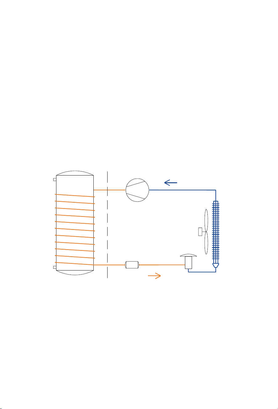
Functioning principles of heat pump water heaters
An air-sourced heat pump water heater mainly consists of a compressor,
expansion valve, filter, evaporator, condenser, fan and water storage tank.
Powered by electricity, the compressor absorbs low-temperature and
low-pressure refrigerant gas from the evaporator. It compresses the gas into
high-temperature, high-pressure gas, which is passed through the condenser.
Heat is transferred to the water from the condenser through the cylinder walls.
The condensed refrigerant is then depressurised by the expansion valve,
allowing it to absorb heat from the surrounding air in the evaporator.
Compressor
Filter
Expansion
valve
Fan
Evaporator
Condense
13
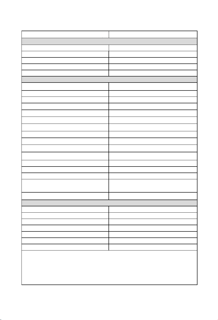
Technical specifications
Model
HP330M1U1
water heater
Tank
Total water capacity 330L
Rated voltage/ frequency
220-240V/50Hz
Tank max pressure
850kPa
Corrosion protection Magnesium rod
Waterproof grade IP24
Performance (20°C/15°C Ambient air temperature, 15°C -55°C water temperature)
COP*@20°C/15°C
4.00
Power input of electric element 2.2kW
Rated power input of compressor
0.7kW
Power input range of compressor 0.2 to 1.2 kW
Maximum power input (total appliance) 3.4kW
Rated heating capacity (compressor)
2.8kW
Heating water capacity
60L/h
Heating up time * 5.5h
Default temperature setting
60°C
Temperature setting range - with heater
35°C - 75°C
Max temperature of the heat pump only
65°C
Max working pressure of refrigerant 1.0/3.3MPa
Refrigerant type / weight R290/0.47kg
Sound pressure level *@ 1m
47dB(A)
Ambient temperature range for appliance -7°C~45°C
-7°C~45°C
Ambient temperature range of heat pump
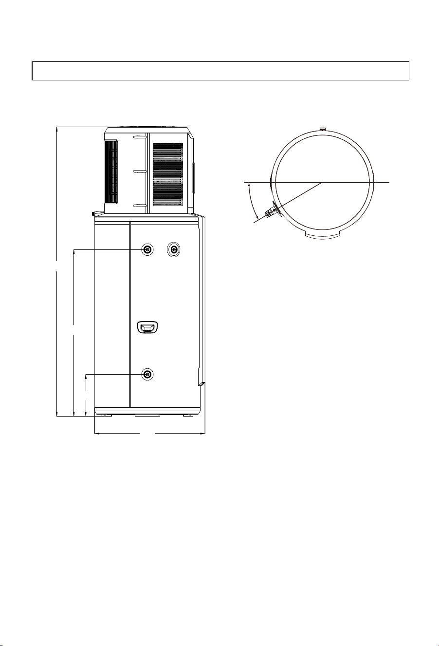
Dimension and connections
Rp ¾”
Rp ¾”
Rp ¾”
(710*758*1941)mm
(745*745*2263)mm
122/150kg
452kg
* The COP was measured under test conditions with an ambient air temperature of 20˚C/15˚C
(Dry Bulb/Wet Bulb) and heating of the water from 15˚C to 55˚C during water heater operation.
* The noise level was measured at 1 m from the water heater during a Noise Test conducted to
Standard GB/T 23137 in a hemi-anechoic chamber within a laboratory.
The voltage that these figures are calculated at 230V.
Water inlet and outlet connection
TPR valve connection
Drain & Water inlet connection
Product Dimensions
Packing dimension with pallet
Net/Gross weight
Filled weight of the appliance
14
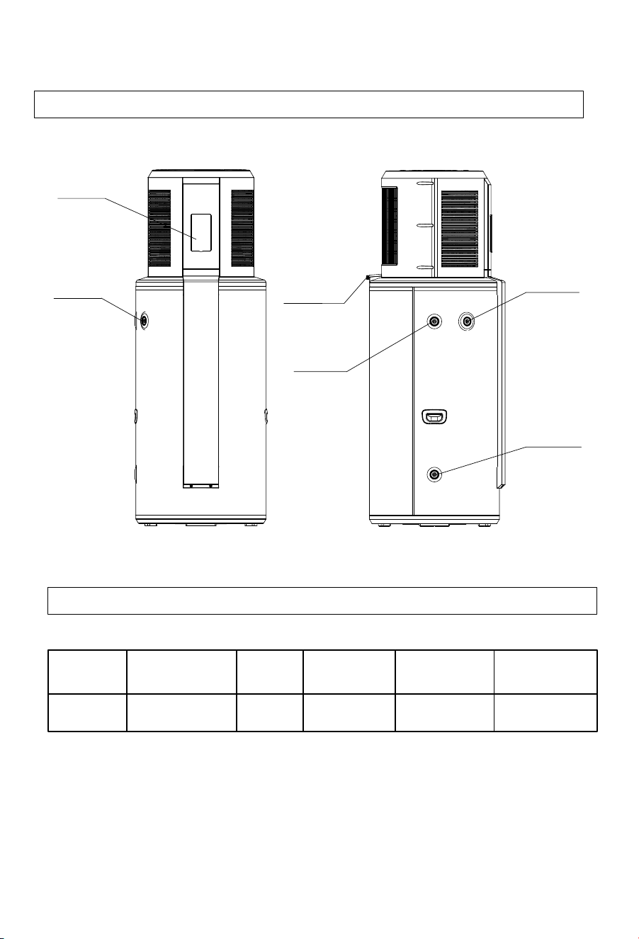
Description of parts and components
Part
name
TPR
Heat pump
water heater valve
Instruction
manual Supply Cable
Condensate
drain Hose
Conduit for
Quantity 1 1 1
1 1
Heat pump layout
Carton contents
15
Display
PTR valve
PTR valve
connection
connection
Hot water
outlet
Condensation
drain
Cold water
inlet
Description of parts and components
16
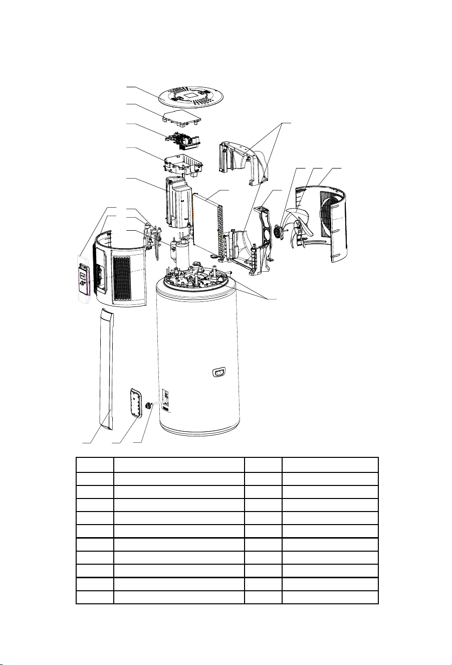
Exploded view of the heat pump
S/N
Description
S/N
Description
1
Display panel & Cover
11
Evaporator
2
Front shell
12
Diversion air duct
3
Top cover
13
Support
4
Electrical box cover
14
DC motor
5
Control panel
15
Fan blade
6
Electrical box
16
Rear shell
7
Compressor cover
17
Magnesium anode
8
Four-way valve
18
Decorative cover
9
Electronic expansion valve
19
Waterproof cover
10
Compressor
20
Heating element
4
6
5
8
9
10
1
2
3
11
7
13
15 1614
12
17
18 19
20

Installation instructions
17
Selection of installation site
1.
During transport or storage, the heat pump water heater should remain in
undamaged packaging to prevent damage to the appliance.
2.
During long periods of transport or storage, the heat pump water heater
must be in an upright position.
3.
For short distance transportation (under one hour), this product may
be laid down within 1 hour as per indication on packaging. If laid down,
the appliance must be at an upright position for 4 hours prior to its initial
startup.
1.
Ensure the install location is stable and level, and that air can flow in
and out freely, and will be minimally affected by wind.
2.
The base or surface can support the filled weight of the appliance and
the condensate water can drain freely.
3.
If installed on a base, ensure that this base is level to allow correct
drainage via the condensate drain at the rear of the appliance.
4.
The location or position of the appliance will not create nuisance
noise for the homeowners or neighbors, especially through proximity to
noise-sensitive areas such as bedrooms.
5.
Ensure that the location allows condensate and PTR valves to be
drained into an area that will not cause damage to the surrounding
area.
6.
There is sufficient space left for installation and maintenance of the
appliance.
7.
There is no strong electromagnetic interference around the appliance
that may affect its control functions.
8.
There are no corrosive vapors such as aerosol sprays, stain removers or
household chemicals near the install location. These vapors may corrode
the appliance and its fittings.
9.
Considerations have been made to prevent water pipes from freezing in
colder regions.
Transporting the appliance
Installation instructions
18
Installation dimensions
1941
1119
282
741
30°
PTR valve
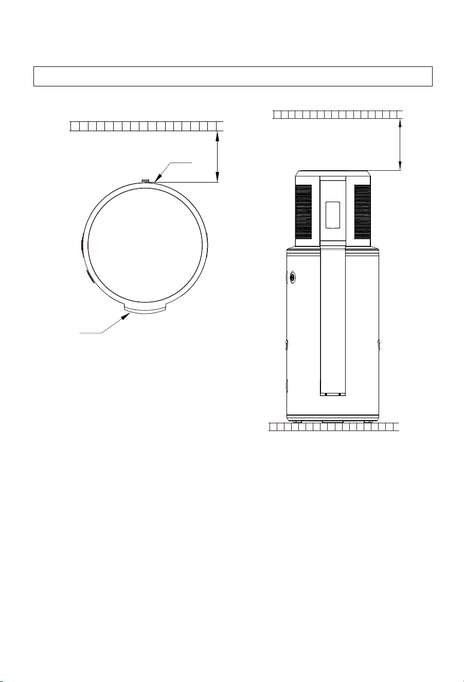
19
Note: This appliance must be installed in a location where it can be
quickly and easily drained and moved to a location with 1000mm
clearance above the appliance. This is so the anode to be removed for
checking and replacing during the 5 yearly service.
Installation clearances
Installation instructions
>300mm
>100mm
Air outlet
Display

20
WARNING — FOR CONTINUED SAFETY OF THIS APPLIANCE IT MUST
BE INSTALLED, OPERATED AND MAINTAINED IN ACCORDANCE WITH
THE MANUFACTURER’S INSTRUCTUCTIONS.
WARNING — THIS APPLIANCE MAY DELIVER WATER AT HIGH
TEMPERATURES. REFER TO THE PLUMBING CODE OF
AUSTRALIA (PCA), AND ALL LOCAL REGLATIONS ON ADDITIONAL
DELIVERY TEMPERATURE CONTROL MUST BE FOLLOWED.
1.
The water heater must be installed:
a. by licensed trades people.
b. in accordance with all local codes and regulations and standards
including AS/NZS3500.4, AS/NZS 3000, and the Plumbing Code of
Australia (PCA).
2.
The inlet water pressure of water supply must be between
100kPa and 500kPa.
3.
Water inlet Connections: An isolating and non-return valve and
line filter (or a combination) must be installed on the inlet of the
appliance. A pressure limiting valve must be installed if the inlet
supply pressure exceeds 500kPa.
4.
If a cold-water expansion control valve (ECV) is required by
regulation, a valve of a maximum of 600kPa should be fitted. The
correctly sized pressure limiting valve should also be fitted as per
the ECV manufacturer's specifications. If no ECV is fitted, the
pressure limiting valve should have a maximum pressure of
500kPa.
5.
Water outlet connections: A thermostatic mixing valve or
tempering valve must be used when hot water is supplied to
fixtures used for sanitary use (i.e. bathrooms) in accordance with
the requirements of AS/NZS 3500.4.
6.
For ease of assembly and disassembly of the appliance, it is
recommended that mechanical joints are used to connect the
plumbing pipework to the water heater.
7.
The water inlet, outlet and PTR/TPR valve must be fitted as per the
labels at the hot, cold and PTR connections.
Plumbing installation
Installation instructions

Installation instructions
21
8.
To avoid damage to the appliance, the inlet water temperature should
remain between 5°C - 40°C.
9.
Before filling the tank, make sure that the cold-water inlet and hotwater
outlet of the appliance are open, along with the farthest hot water fixture
are opened. The appliance will be correctly filled once water flows
continuously from this fixture without air bubbles. Venting through
the PTR/TPR valve may cause premature failure of this valve.
10.
If there is a risk of the hot water line, cold water line or PTR/TPR
valve drain freezing, the pipework must be insulated with an
appropriate 20mm thick insulation material. Failure to adhere to
this requirement may result in a voided warranty if the damage is
due to freezing.
11.
In accordance with the safety rules, a PTR/TPR valve must be
installed directly into the appliance's PTR/TPR valve connection.
(This valve is rated at a maximum pressure of 850kPa, a maximum
operating temperature of 99°C, and a connection size of 3/4”). Never
block the outlet of the PTR/TPR valve, the ECV, or their drain lines for
any reason.
Plumbing installation continued
Installation instructions
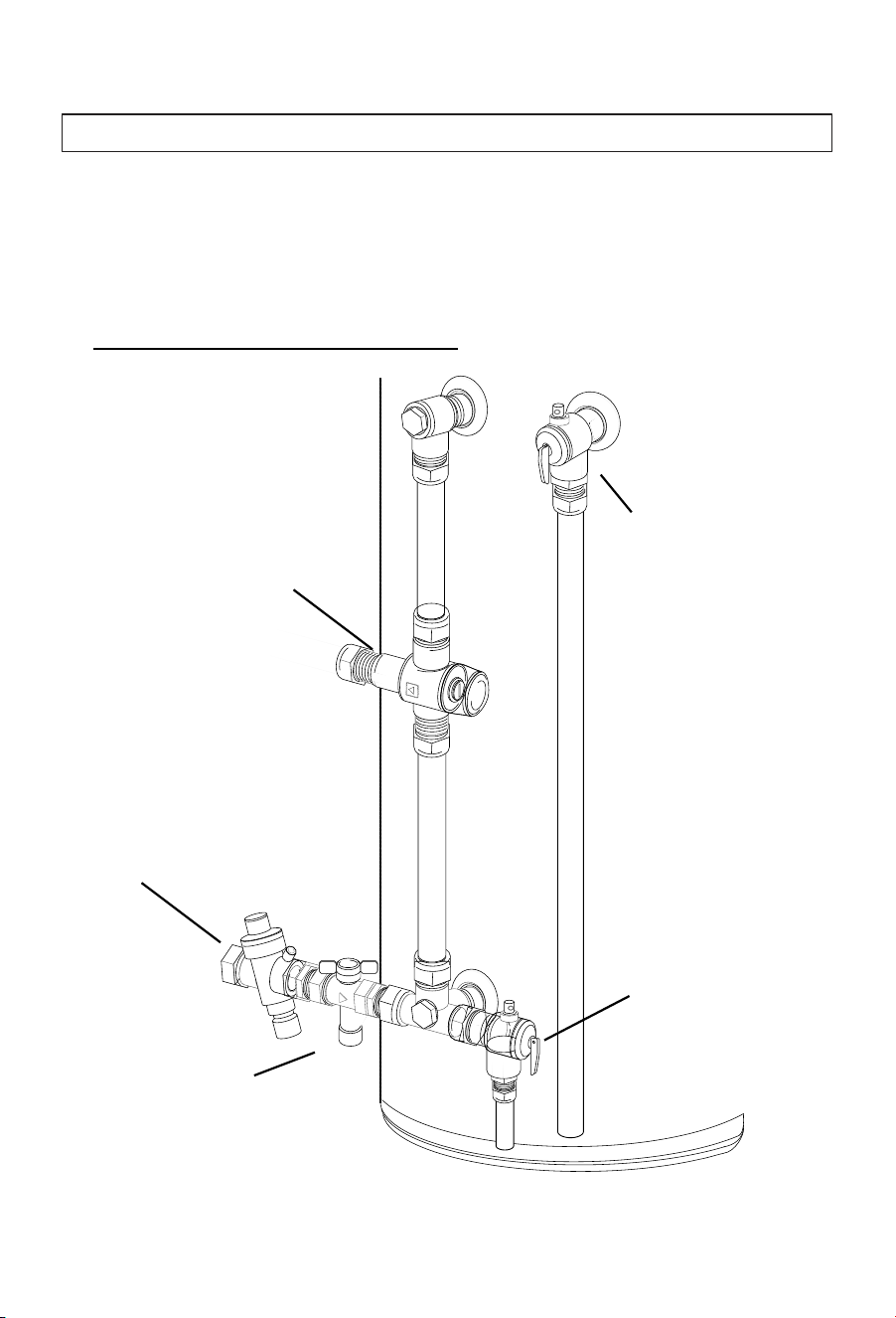
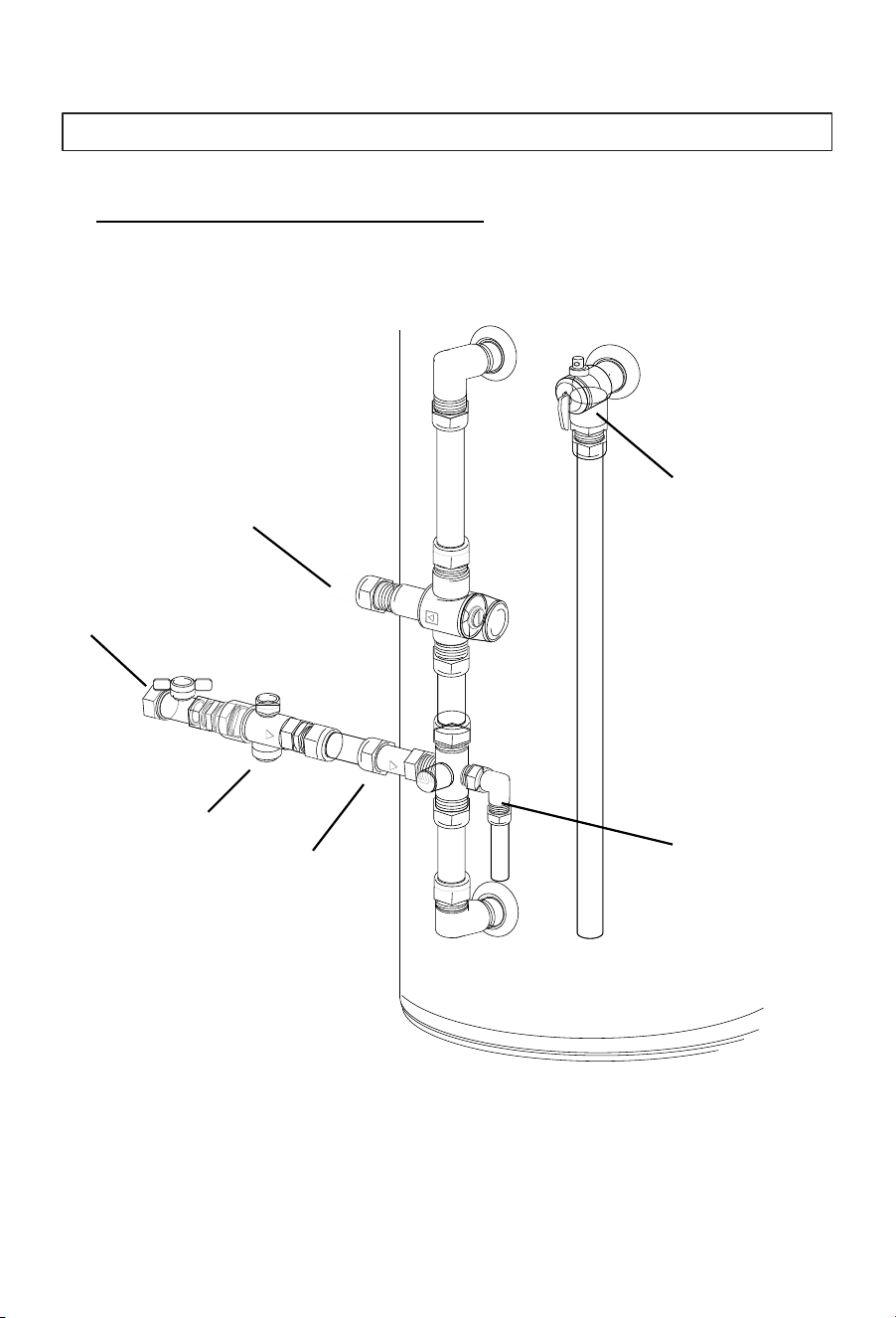
22
Although the plumbing inlet and outlet layouts can differ between
New Zealand and Australia, they effectively carry out the same
functions.
Typical Australian Pipework Valve
Cold water
expansion valve
Line strainer
Isolating valve
PTR valve
Thermostatic mixing valve
Supply valve configurations
Installation instructions
23
Typical New Zealand Pipework Valve
Supply valve configurations
Thermostatic mixing valve
TPR valve
Isolating valve
Cold water
expansion valve
Inlet filter
Non-return valve
Installation instructions
24
Condensate drain
Warning: Ensure the condensate drain cannot become blocked and flood
condensate tray.
Ensure the condensate drain is a minimum 20mm in diameter.
Ensure that drainpipe has continuous downward fall to allow it to
drain freely.
Make sure the condensate drain is open to the atmosphere to
prevent airlocks.
Installing the condensate drain
A flexible condensate drain is supplied as an accessory to this appliance.
This drain hose is connectable to the condensate drain hose connection
located at the rear of the appliance.
Note: The condensate from this appliance is pure water. It should be drained
to a gully trap or to a location such as a garden bed, in a way that won’t cause
and damage or nuisance to the surrounding area.

25
CAUTION: In order to avoid inadvertent resetting of the thermal cut-out, this
appliance must not be supplied through an external switching device, such
as a timer, or connected to a circuit that is regularly switched on and off by
the utility (off-peak electrical line).
Electrical Safety Requirements
The installation, service or repair of the electrical components of this
appliance must be completed:
Electrical installation
Installation instructions
By a qualified and licensed electrical trades person.
By the local electrical codes and regulations and standard AS/NZS
3000.
During the electrical wiring of this appliance, the surrounding conditions
(ambient temperature, direct sunlight, wind, and rainwater) shall be
considered. Effective protective measures shall be taken to suit the
installation's environment.
Must use materials certified to local standards for local conditions.
The circuit to the appliance should be a minimum of 2.5mm²2-core
and earth.
The communication Cable (Part number 23 on Page 9) is for use with a
Photovoltaic power system is used. When not used, this cable can be
coiled up and located neatly outside the cylinder or inside the Heat pump
casing in a safe location.
The appliance must be correctly and reliably earthed.
The appliance must be connected to a dedicated circuit. This Circuit
must be fitted with a circuit breaker no greater than 20 Amps. A residual
current device (RCD) is also recommended.
26
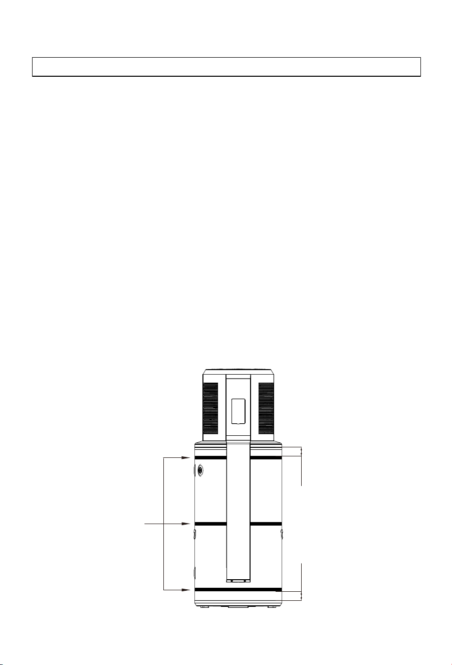
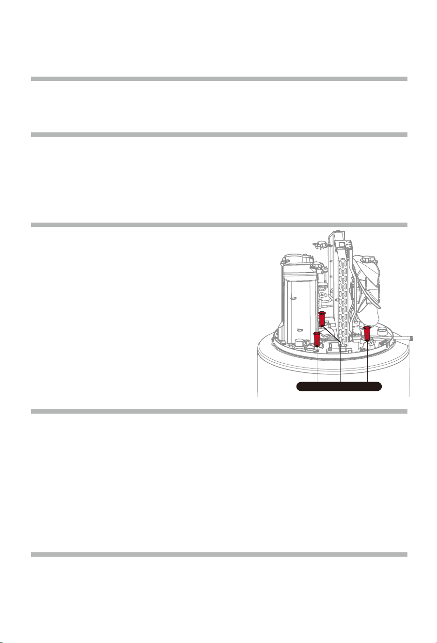
FOR NEW ZEALAND INSTALLS ONLY
In New Zealand, the appliance must be seismically restrained with three
seismic straps in accordance with the NZBC (G12/AS1) and
AS/NZS3500.4.
To meet this requirement this appliance should be fitted with three
stainless steel straps, 25mm wide x 1mm thick.
These straps should be fitted as per the following instructions:
The appliance must have adequate airflow at the rear of the appliance,
as this is where the outlet to the heat pump is located. When seismically
strapped, the appliance can be braced 100mm from the wall or be
installed at a 45°C angle with 50mm braces to allow sufficient airflow.
Top strap: Under the front cover, and no more than 100mm from the top the
painted cylinder section of the appliance.
Middle strap: Under the front cover, at the center of the painted cylinder
section of the appliance.
Bottom strap: Below the front cover, and no more than 100mm from the
bottom the painted cylinder section of the appliance.
Seismic straps
Seismic strapping
Installation instructions
<100mm<100mm
27
Commissioning checklist
Installers should check that the following tasks have been completed correctly
during the commissioning of this appliance.
The appliance is placed on a level surface that can hold its filled weight.
The electrical connections are correctly made to local installation
standards.
The water connections have been correctly fitted and are leak-free after
the appliance has been filled and pressurised.
Check to make sure the water is heating.
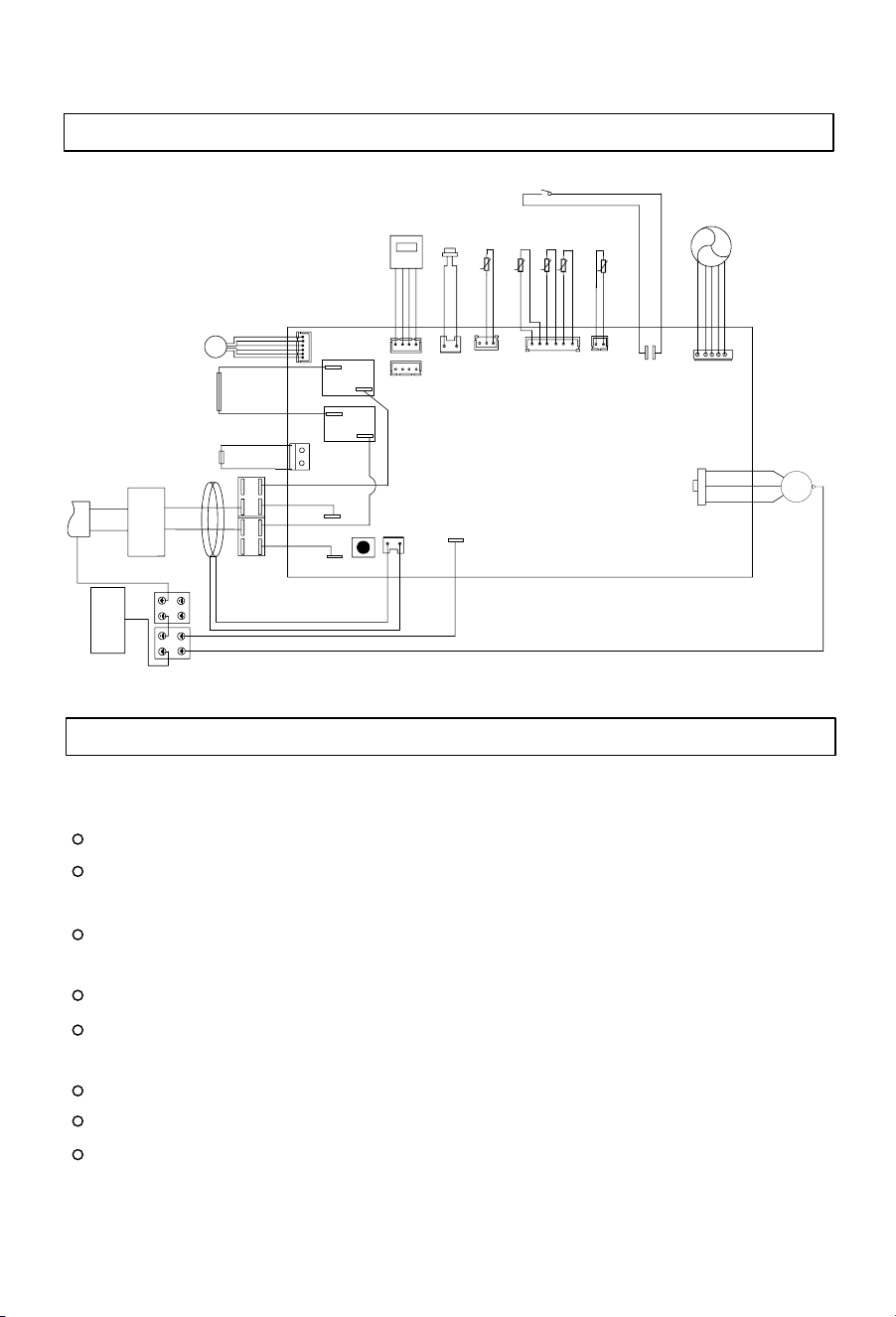
Wiring diagram
Installation instructions
The control panel is operational (the display is active).
All hot water pipework is insulated.
All cold water and drain pipework is insulated if required.
The supplied PTR / TPR valve has been correctly fitted to the appliance
and releases water when the lever is activated.
CN19
CN7
CN11
CN16
CN15
EXV
CN9
K1
CN8
CN10
SW1
CN6
K2
CN22
CN20
CN21
U
V
W
Red
L
N
CN32
CN31
MAIN BOARD
FAN
High pressure switch
Expansion valve
Leakage
protection coil
Water tank temperature
sensor
Suction sensor
Exhalation sensor
t
t
Defrosting sensor
Environmental sensor
CN18
Four-way
valve
Electric heating
element
Brown
Brown
Brown
Brown
Blue
Blue
Blue
Blue
GND
Over-t
e
mpe
a
tur
e
th
e
rmo
s
tart
White
Black
Compressor
Yellow-green
Yellow-green
Yellow-green
N-OUT
N-IN
L-OUT
L-IN
Valley valve electric signal
Yellow-green
Electric
wire
Electric heating
element
Brown
Blue
Display panel
Terminal
strip
t
t
t
U
V
W
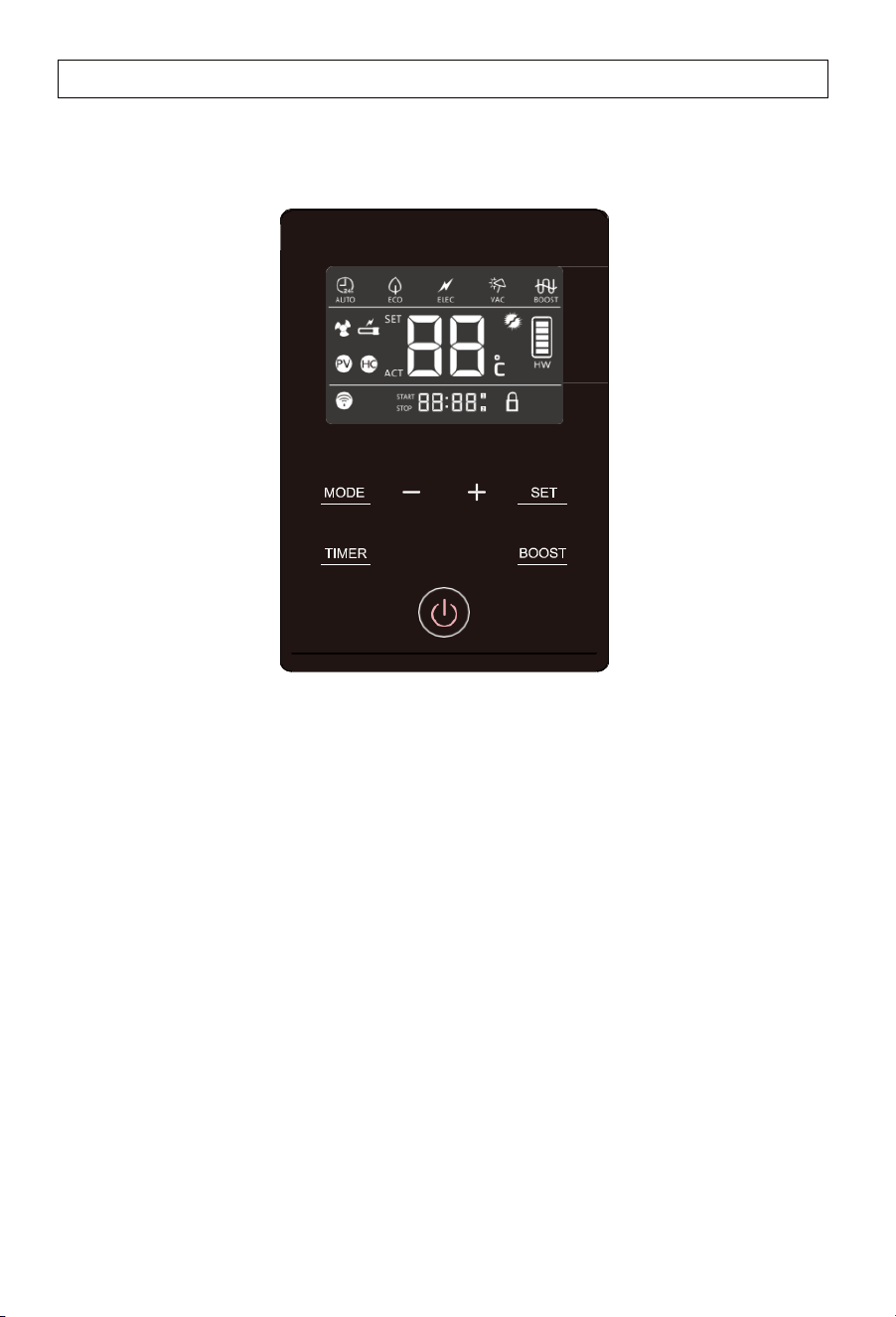
Description of the icons
28
Functions & Protections
A.
Electrical leakage protection
This appliance features an electricity leakage protection function.
B.
Compressor protection
Whenswitchedon, theappliance willtake approximately 3minutes to start the
compressor for heat pump heating.
C.
Automatic defrosting function
The defrosting mode is automatically activated if the outdoor temperature is
low and the compressor has run for some time.
D.
Overload protection
The working load of the compressor will be high in warm ambient air
temperatures. To meet hot water requirements and to lengthen appliance
life, this product automatically adjusts the fan speed to ensure reliable
operation of the compressor.
E.
Anti-freezing function
The heat pump maintains a minimum temperature to avoid damage to the
appliance caused by freezing.
Description of the icons
29
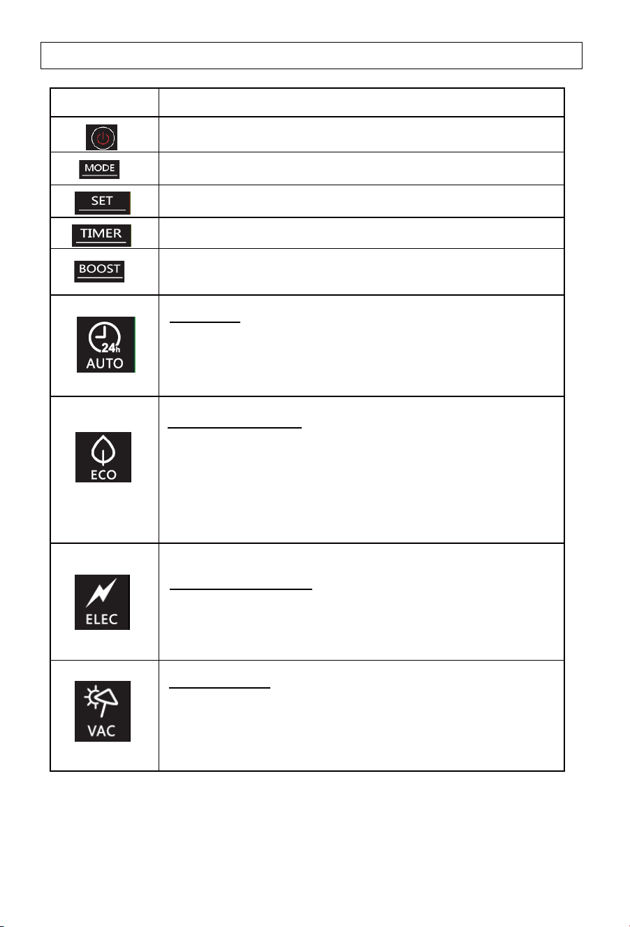
Symbol
Description
Power ON/OFF switch
Working mode selection
Confirming the selection
Timer adjustment
Boost mode. Heat pump and backupelement heat
simultaneously to speed up hot water recovery
Auto mode
-
Heats primarily via theheat pumpas hot water is required.
The back-up element is activated if expected heating times
are exceeded.
ECO (off-peak) mode
-
Prioritizes heatpumpheating to match either
1 - User programmed timer settings
2 - Smart Grid (SG) mode via comms signal.
3 - Solar PV (PV) mode via comms signal.
Electric heating mode
- A service menu, for use when the heat pump module is
faulty. Uses only the backup element for heating.
Vacation mode
- Maintains a minimum temperature to prevent freezing, then
heats to the set temperature for the owners return. The
number of days is programmed by the owner.
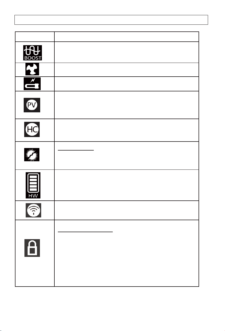
Description of the icons
30
Symbol
Description
Boost mode. Heat pump and backup element are activated at
the same time.
Icon indicating that the heat pump is activated.
Icon indicating that the back-up heating element is activated.
PV Mode. When the PV signal is received, the appliance will
revert to pre-set PV mode settings.
Smart Grid (SG) mode. In Time of peak/off-peak hours mode,
the symbol corresponding to the mode is displayed.
When receiving the signal, the HC icon will illuminate.
Hot water volume display. Shows heating required to get to the
maximum set temperature of 65°C.
WIFI signal icon
Lock screen display icon
1.
Enter: In the power-on state, press and hold TIMER+BOOST
(combination key) for 6s at the same time, the lock sign will be
on, and the screen lock mode will be turned on.
2. After the screen lock mode is turned on, the device will not
respond when the user touches any key.
3. Exit: press and hold TIMER+BOOST (combination key) for
6s at the same time, the lock sign is closed, and the screen
lock mode is exited.
Note: Under certain conditions, ECO mode may result in shortages of hot water if
the ambient air temperature is low.
Anti- legionella
-
Anti-legionella function will be activated every 7 days to
heat the tank to 61°C automatically.
Operating functions
31
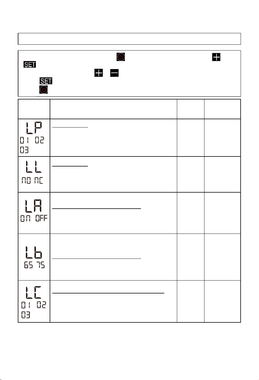
Installer settings & WIFI connection
- To open the installer settings, press switch off the system, then press and
at the same time for 10 seconds.
- When menu is open, press or to change the value of the settings.
- Press to confirm the settings.
- Press to close the menu.
Parameters
Description
When using the SG or PV comms signal line, sets to match
the relay/dry contact signal received.
Eco mode type
Comms signal type
- Sets the applaince to the Eco mode options.
-01:
User programmed timer function.
-02: Smart Grid (SG) mode via comms signal.
-03: Solar PV (PV) mode via comms signal.
NO
01
NO , NC
01 , 02 , 03
01 , 02 , 03
Factory
setting
Adjustment
range
- NC corresponds to Normally Close Signal.
- NO corresponds to Normally Open Signal.
,
,
ON OFF
,
PV function can be executed in AUTO mode
(when 03 is selected in LP)
-ON allows PV mode activation in Auto mode.
-OFF prevents PV mode activation in Auto mode.
Temperature setting in PV function
(when 03 is selected in LP)
The temperature setting is adjustable between 65°C and 75°C.
Heat source selection in PV function (03 isselected in LP)
-01 Heat pump and element work simultaneously.
-02 Heat pump heating.
-03 Element only heating.
-
65
65-75
01
,
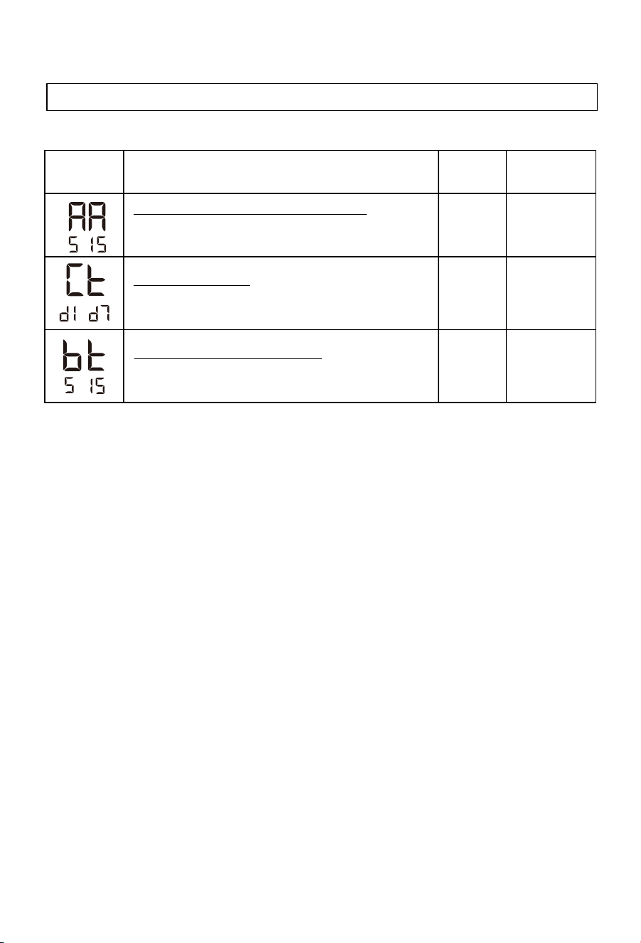
32
-
Compressor maximum continuous working time
- If themaximum continuous working timeof the compressor
more than Set Time, start auxiliary power.
10h
5-15h
-
Set the day of the week
- Set the day of theweek, d1 to d7 for Monday to Sunday, and
remember the day of the week.
/
d1-d7
Reheat differential temperature setting
- Reheating will start in the 330L at 10°C below the
set temperature. The adjustment range is 5-15°C.
10 5-15
Installer settings & WIFI connection
Operating functions
Parameters
Description
Factory
setting
Adjustment
range
-

33
Connecting to WIFI & SmartHQ
Operating functions
Step one: Make sure the appliance is connected to power but is switched
off using the (On/Off) button. The actual temperature of the appliance should
be visible.
Step two: Ensure your home Wi-Fi network is switched on and has good
signal strength from the appliance location.
Step three: Ensure that your smartphone has Wi-Fi and Bluetooth switched on.
Step four: Press and hold the (-) button on the appliance to enter ‘pairing
mode’. The Wi-Fi icon will flash when the pairing mode is activated. Once a
successful connection to the SmartHQ app is made, the Wi-Fi will stay
illuminated.
Step five: Download the SmartHQ app from the Apple Store or Play Store.
A direct link to the SmartHQ app can also be found at
Step six: Open the SmartHQ app, register and create an account.
Step seven: Add the Monoblock by clicking the “Add an appliance button”
on the app, then select the ‘water heater’ option. From there, select the
water heater by working through the qualifying questions on the app.
Step eight: Once the correct appliance is selected, it may take up to 10
minutes for the appliance to connect and for the app to start functioning.
For more information on setting up SmartHQ visit
.www.fisherpaykel.com/connect
https://support.fisherpaykel.com/s/article/Setting-up-with-SmartHQ
.

34
Programming the timer function
Operating functions
1. Step 1: Ensure the Eco Mode is set to ‘timer mode’.
Open the service menu, press (+) and (SET) with the appliance
in standby and hold for 10 seconds.
Press ‘SET’ until LP (LP – Eco Mode Setting) is visible.
With LP visible, if “01” is shown then the timer function is set. If
not, press (+) or (-) until the screen shows “01”, and then press
set.
a.
b.
c.
2. Step 2: Ensure the ‘day of the week’ is set correctly.
3.
Note: The weekday heating periods are labelled L1 & L2, and the weekend
heating periods are labelled L3 & L4.
Note: Ensure that a sufficient heating periods are allowed per each 24 hour
period. Failure to do this may result in insufficient hot water supplied. Please
see the heating time chart on page xx. (add the heating chart).
Note: Programming one heating period time per day is sufficient. If the second
period isn’t required, leave both the start and stop times at: for the second
period (i.e. L2 and L4).
Step 3: Set the heating periods (2 periods for weekdays and 2 periods
for weekends).
Still in the service menu, press (SET) to until ‘Ct’ is displayed. (Ct
– Set the day of the week).
Press (+) to change the displayed value (d1 to d7) to program the
day of the week. This sets the day where 01 is Monday, and 07
is Sunday. Press set to confirm.
Press the (SET) button until the service menu is exited. The
screen should now display the ‘actual temperature’ of the water
inside the cylinder.
a.
b.
c.
Ensure that the appliance is switched on using the on/off button.
Ensure the product is set to ECO mode. Press the MODE button
until the Eco mode symbol is displayed.
Press the SET button until the display shows the hour and minute
section flashing “00:00” along with “L1” displayed. Hours will flash
first, set the desired time then press SET. The minutes will flash,
prog.
a.
b.
c.

35
Programming the timer function
Installing the PV communication cable
Operating functions
WARNING: For the appliance to heat on weekends, at least one weekend
heating time (either L3 or L4) must be set.
Note: Each solar PV and smart-grid communications system can be set up
using a different method. To understand how each inverter or smart grid
comms unit is set up, please contact the manufacturer of the solar PV
inverter or smart grid comms module.
Warning: Installation must be carried out only by a licensed electrician
This appliance is fitted with a communications cable for connecting to solar
PV and smart grid systems. This cable is designed for connecting to dry
contact connections from these systems.
Press the + or – buttons to move the time to the START time of
the L1 heating period. Press SET to confirm this time. Then,
move the time to the STOP time of the L1 heating period and
press SET to confirm.
d.
If a second weekday heating period is required, adjust the times
for L2 using the same process as step 2.c. If no additional
weekday heating period is needed, press SET at 00:00 for both
the start and finish times of L2. Repeat steps 2.c and 2.d for the
weekend heating times.
e.
1. Step one: With the appliance off The Haier heat pump comms cable
comes fitted inside the appliance module. To find this cable, remove the
cover of the appliance by removing the 8 x screws of the module cover.
You will need to unplug the IU/controller.
2. Step two: Connect a communications cable to the correct standard
(2 x1.5mm). Make the connection inside the module. The connection
should remain inside the module, with the communications cable fed
through the cover to the inverter or dry contact fitting.
3. Step three: Wire the other end of the comms cable into the dry contact
of the solar PV inverter or its communications accessory.
36
Programming the timer function
Operating functions
Note: The power supply cable and the communications cable need to be
run in separate conduit pipes. Preparation should be taken to keep these
lines separated from each other.
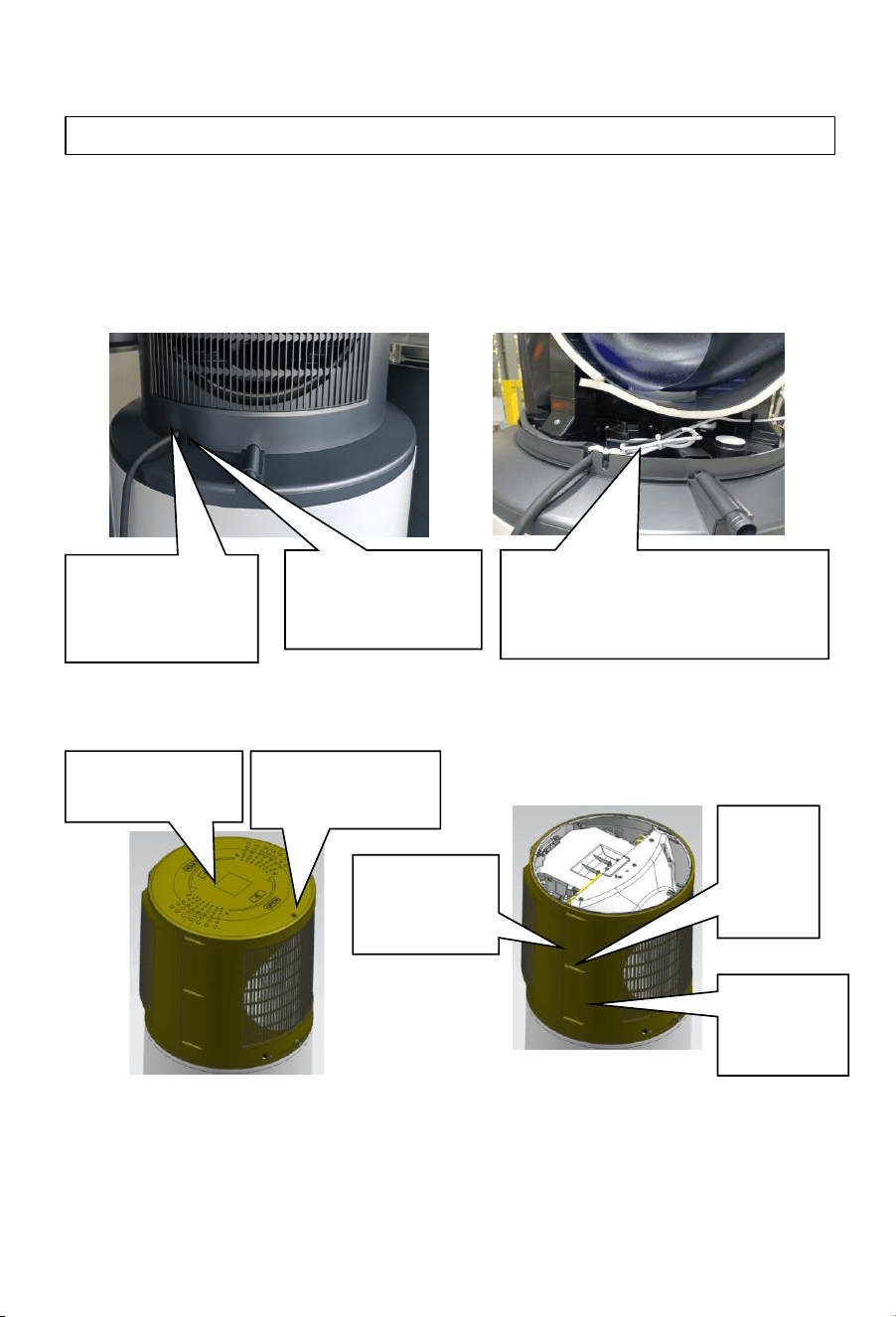
Remove the service cover fixing screws. The service cover rotates
counterclockwise to be removed. Remove the 6 cover shell fixed screw
to remove the front & rear shell.
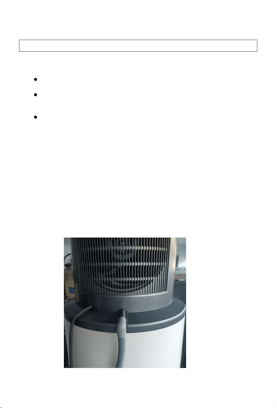
Communication cable location:
Cover shell disassembly:
Power line out
of the box
position
The signal wire bundle is
positioned near the wire
clamp clip the hood
Location of the
signal line out
of the box
Service cover
fixing screws
Maintenance
cover
Front over
shell
The rear
cover
shell
Cover
shell
fixed
screw

37
Programming the PV Mode
Operating functions
Note: The solar PV inverter or comms box should have the ability to program
a power export threshold at which the dry contact switch will be activated. It
may also allow programming for ‘closed’ for activated or ‘open’ for activated.
Take note of which option the relay is set for.
1. Step 1: Program the threshold setting in the inverter or comms module,
understanding if it will be signaled by an open or closed switch.
2. Step 2: Ensure the PV comms signal type is set.
3. Step 3: Ensure the Eco Mode is set to ‘PV mode’.
Open the service menu, Press (+) and (SET) with the appliance
in standby and hold for 10 seconds.
The screen should show LL, indicating the PV comms signal type
adjustment. Change this to NO (normally open) or NC (normally
closed) to match the signal setting on the inverter or comms
module.
a.
b.
Still in the service mode, Press (SET) to change the displayed
value to (LP – Eco Mode Setting).
Press (+) or (-) until the screen shows “03 – PV mode”, and then
press SET.
a.
b.
4. Step 4: Program the PV mode settings to suit the application.
Use the table on page 34 to understand the setting requirements
for the application.
In the service mode, program the settings shown in the table for
LA (PV function activation in Auto mode), Lb (Temperature
setting in PV mode), and LC (Heating selection in PV mode).
a.
b.
5. Step 5: Change the user settings of the appliance.
With the appliance switched on, press the MODE button until
the appliance is in ECO mode. The ECO symbol with the leaf
should be illuminated.
Change the standard set temperature (i.e. the set temperature
for when the appliance isn’t receiving a PV signal) to match the
requirement in the table on page 34.
a.
b.

38
Operating functions
PV comms
signal type
Displayed code LL
Factory Setting NO
Code option NO, NC
Description
NO = Normally
open
NC = normally
closed
Programming method
The most efficent use of energy
PV System
Dependant
Heats only when Solar PV electricity is available
PV System
Dependant
Highest assurance that hot water will be available.
PV System
Dependant
Storing the highest volume of hot water
PV System
Dependant
The fastest recovery of hot water/ using PV energy quickly
PV System
Dependant
Eco mode
setting
PV function
activation in
Auto mode
Set Temperature
(AUTO w no
PV Supply)
Temperature
setting in PV
mode
Heating selection
in PV mode
User Mode
LP
LA
Lb LC AUTO, ECO, ELEC
01
ON
65 01
01, 02, 03
ON, OFF 65 - 75 01, 02, 03
01 = Timer
mode
02 = Smart
Grid mode
03 = Solar PV
mode
ON = PV mode
will activate in
AUTO mode.
OFF= PV will not
activate in AUTO
mode.
Adjusts the set
temperature
when PV mode
is activated
01 = Heats via HP
& element
similtaniously.
02 = Heats via the
HP, then element
above 65°C.
03 = Heats via the
HP only.
AUTO = Auto
mode
Eco = Eco mode
for PV.
ELECT = Electric
only mode for
servicing
03 ON 65 AUTO
03
OFF 75 ECO
03 ON 75 AUTO
03 ON 75 AUTO
03 ON 75 ECO
User Settings
35 - 75
35 - 75
60
35-75
35
50
35
35
-

39
Hot water recovery & heating times
Operating functions
Ambient air temp
(dry/wet) (
°C)
Start water
temp (°C)
Finishing water
temp ( )
Heating
time (h)
2/1
9
60
13.48
9/8
9
60
9.58
19/15
9
60
5.82
33/26
9
60
5.17
As the ambient air temperature decreases, the efficiency and heat
output of the heat pump also decreases. Lower air temperatures mean that
there is less heat to be extracted from the air, which directly leads to the
reduction of heat production from the heat pump unit.
In a low temperature environment, the surface of the evaporator can
easily frost. This increases the heat transfer resistance and the time taken to
transfer the heat to the water. In frost conditions, the heat pump will
periodically switch to a defrosting mode in place of heating, which also
extends the heating time.
°C

Checking and maintenance
40
Checking the PTR valve
-
Operate the PTR valve at least once every six months to ensure it functions
correctly. Lift the lever on the PTR valve. It should release water for 5 seconds.
Gently lower the lever until the water stops. Do not let the lever go, as this could
damage the valve. If water is not released, contact Haier Customer Care or a
qualified plumbing tradesperson to resolve the issue.
Excessive discharge from the PTR valve
-
A small quantity of water is expected to be released from the PTR valve during
each heating cycle of a storage water heater. If the volume is greater than a
bucket of water every 24 hours or there is continuous running or dripping of
water from the valve, there may be an issue with the valve.
-
If there is a continuous run from the valve, gently activate the valve lever for a
few seconds. If the discharge stops, foreign matter may have been dislodged
from the valve. If the PTR valve continues to run at a high rate, the water
pressure exceeds the design pressure of the water heater. This issue can be
resolved by a plumber fitting a Pressure Limiting Valve (PLV). Alternatively, the
valve might be faulty and need replacing.
Checking the expansion control valve
-
The cold water expansion control valve is expected to allow a small quantity of
water to be discharged during the heating cycle. If it discharges more than a
bucket of water per day or continuously, there may be another issue. If the valve
leaks continuously, try easing the lever for a few seconds. This will dislodge any
foreign matter that could cause the issue.
-
Operate the valve’s lever often to remove foreign matter and check for a
blockage in the valve’s drain line.
- Installation and maintenance of the appliance must be undertaken by a
qualified professional.
- Before working on the appliance, shut down the machine and cut off the
power supply at the switch.
- Do not touch with wet hands.
- Maintenance operations are important to guarantee optimal performance
and extend the life of the appliance.
Checking and maintenance
41
Checking the pipework
-
Check the water tightness of the water pipework connections and pipework.
Drainpipes should drip occasionally, but they should not run.
Checking the condensate drain
-
Check the condensate drain on the appliance. If it blocks, it may cause the heat
pump to flood.
-
Also, check the drainpipes from the PTR valve and CWEV. They should flow
freely and should not be blocked.
Cleaning the fan & evaporator
-
The fan should be checked annually for dust buildup. If cleaning is required,
contact Haier Customer Care or a qualified professional.
Scrapping and refrigerant recovery requirements
Only a qualified professional can scrap the appliance, safely recovering the appliance's
refrigerant. Contact Haier Customer Services for advice on correctly disposing of this
appliance.
-
Checking and cleaning the evaporator must be completed by a qualified
professional.
-
It is recommended that the evaporator is cleaned every two years.
-
Clean the evaporator with a soft brush and water if required. Do not use
cleaners on the evaporator fins.
Checkingthe anode
- Checking and replacing the anode must
be carried out by a qualified plumbing
tradesperson.
- To avoid irreversible corrosion of the
cylinder, it is recommended to check the
anode every five years and replaced if
required.
Magnesium anodes

Faults and protection
42
Water Quality
A breach of this condition may void the warranty if exceeding these
characteristics causes damage to the water heater.
Water supply from an unfiltered source that is highly conductive or has a high
mineral content may void the system warranty.
The following characteristics should be within the warranty conditions not to
be breached.
Please be advised that in areas of geothermal activity where sulphur or salt
contamination or corrosion may occur, additional protection to your
appliance's copper pipework will be required.
Please contact Haier Customer Services for appropriate advice.
Magnesium 10 mg/litre or ppm
Total hardness
200 mg/litre or ppm
Chloride
250 mg/litre or ppm
Sodium
150 mg/litre or ppm
Electrical conductivity
850 μS/cm
600 mg/litre or ppm
pH
Min 6.5 to Max 8.5
Total Dissolved Solids (TDS)
Water Properties
Acceptable Levels
Faults and protection
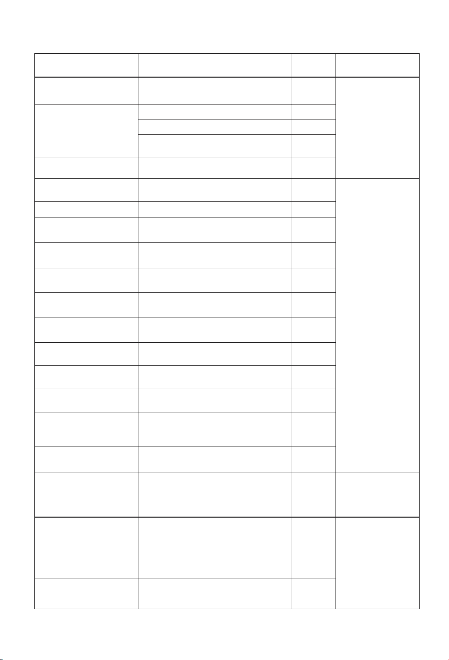
43
Fault type Action
Digital
indication
Release
Communication fault
Communication failure between Wi-Fi
module and control board
F0
Compressor protection
Operating temperature protection
F2
Air exhaust temperature protection
F3
Evaporation high temperature
protection
F5
Compressor over-current
protection
Over-current protection
F6
Electricity leakage alarming
Automatic disconnection of power supply
due to line fault
E1
Please call Haier
CustomerService to
resolve the issue.
Over temperature alarming The actual water temperature≥85°C
E2
Fault of the inner
temperature sensor
If short circuit or circuit break occurs
to the sensor
E3
Fault of the ambient
temperature sensor
If short circuit or circuit break occurs
to the sensor
If short circuit or circuit break occurs
to the sensor
If short circuit or circuit break occurs
to the sensor
If short circuit or circuit break occurs
to the sensor
Abnormal communication of main control
panel and display panel
Action of the pressure switch at the
exhaust outlet
Ambient or outdoor temperature
<-7°C or>45°C
If not received the Off-peak signal
when selecting switch signals by
power companies
E4
Fault of the evaporation
temperature sensor
E5
Fault of the air-exhaust
temperature sensor
E6
Fault of the air intake
temperature sensor
ED
Communication fault E7
Pressure switch protection
E8
Ambient temperature
protection
E9
Fault of the Off-peak
power switching signal
EF
Fault of the fan
Transient hardware
overcurrent of the
compressor phase current
Fan blade is stuck or fan and control
panel communication failure
The MCU detects a low level input at
the FO port or a bus current greater
than the 19.4A peak threshold set by
the MCU internal comparator
L7
P1
Switch the appliance
off then on again.
Compressor phase current
software transient
overcurrent
The instantaneous output current is
greater than 17A
IPM module temperature > 100 ° C
P2
The heat sink (IPM)
temperature is too hig
P3
Appliance auto
corrects. Please call
Haier Customer
Services if the fault
remains\
Please call Haier
CustomerService to
resolve the issue.

Faults and protection
44
Input overflow load
The input current RMS exceeds 18A or
peak output current is >17A
P4
undervoltage protection
Bus voltage below 200V lasts for
5ms
P5
Over Voltage Protection
PFC voltage or bus voltage VDC
greater than 390V for 5ms
P6
The communication
between the main control
chip and the driver chip is
abnormal
The master control and driver
cannot receive data or a data error
persists for 2 minutes
P7
The current detection on
the frequency conversion
side is abnormal
Before the compressor is in
operation, there is a 10%-20%
deviation between the AD value of
the incoming voltage detected by
the sampling circuit and the AD
value of 1.65V
P8
Compressor out of step
The actual running speed of the
compressor is less than 50% or
more than 120% of the target
speed of the drive for more than 5S
PB
Instantaneous Software
Overflow on the rectifier
Side
The instantaneous value of the
input current is greater than 30A
for 3 times, and each PWM cycle is
detected once
PD
Transient hardware
overcurrent
on the rectifier side
PF
Switch the appliance
off then on again.
Appliance auto
corrects. Please call
Haier Customer
Services if the fault
remains\
The instantaneous input current is
greater than 31A for four times
Fault type Action
Digital
indication
Release

Faults and protection
45
The symbol on the product or on its packaging indicates that this product is
not to be treated as regular household waste. It must be taken to a recycling
collection point for electronic equipment. By properly disposing of this product,
you are contributing to the preservation of the environment and the wellbeing of
your fellow citizens. Improper disposal is hazardous to health and environment.
You can obtain further information on how to dispose of this product correctly by
calling Haier Customer Service.


Haier Appliances
Australia 1300 729 948 | haierhome.com.au
New Zealand 0800 424 372 | haierhome.co.nz
Fisher & Paykel Australia Pty Ltd, Level 1, 1 Eden Park Drive, Macquarie Park, NSW 2113.
Phone Customer Care: 1300 729 948.
Fisher & Paykel Australia Pty Ltd, 78 Springs Road, East Tamaki, Auckland 2013.
Phone Customer Care: 0800 424 372.
0040514026
20241127
V*****