01
BODY BIKE INDOOR CYCLING APP
INSTRUCTIONS
BODY BIKE
®
INDOOR CYCLE
BODY BIKE
®
CONNECT
ENGLISH

Equipment required 3
Introduction 4
Certification 5
Specifications 6
General information 7
Warranty 8-10
Assembly
Unpacking 12
Bottom frame 12-13
Handlebar 14
Bottle holder 14
Console 15-16
Saddle 17
Pedals 17-18
Maintenance
Cleaning 20
Sidewards play in posts 21
Cleaning the posts 22
Adjustment handles 22-23
Replacing the brake block 23-24
Poly-V belt 25
Replace console box batteries 26
Replace console batteries 26
Resetting load cell 27
Removal of side covers 28
TABLE OF CONTENTS
Using the console
On, off and reset 29
Keys 29
Default settings 29-30
Tips and information 31
Heart rate 32
Age or MHR and weight 33
Watt test 33-34
Navigation and scan 34-35
Support
Troubleshooting 36-37
Online information 38
Index 39
02

Unpacking
Drill bit
Drill
Bottom frame
13 mm wrench
Saddle
14 mm wrench
Pedals
15mm pedal wrench
Grease
Cleaning
Tissue paper or cloth
Spray bottle with water
Soap (only washing-up liquid)
Vaseline oil
Post cleaning
Cloth
Vaseline oil
Console
3mm and 4mm Allen Wrench
Sidewards play in posts
A coin
3mm Allen wrench
32mm wrench
Adjustment handle
5mm Allen Wrench
Screwdriver
Steel brush
Grease
Brush
Brake block
A coin
8 mm wrench
Poly-V belt
A coin
10 mm Allen wrench
19 mm wrench
Measuring device
Side covers
A coin
3,4 and 8 mm Allen wrenches
13 mm wrench
EQUIPMENT REQUIRED
03
This manual provides information on the assembly and
maintenance of the BODY BIKE® indoor cycle. The manual
is intended for the owners and service people responsible
for cleaning and maintenance.
Before assembling the cycle, please read the manual and
prepare the correct tools, see equipment required page
2. When assembling the cycle, we recommend that you
follow the manual step by step.
Maintaining the cycle is very important. In the manual you
will find clear instructions on how to maintain the cycle.
Over time it will be necessary to replace worn-out parts.
You will find a detailed description and exploded drawings
of BODY BIKE®’s spare parts on our website www.body-
bike.com. When ordering spare parts from the local BODY
BIKE® distributor, please refer to the item number (P/N
no.) in order to make sure you will receive the correct
spare part.
We recommend that you order original parts, accessories
and materials necessary for the maintenance of the cycle
at your local BODY BIKE® distributor.
For further information on accessories, please check our
website www.body-bike.com
INTRODUCTION
04

Federal Communication Commission In-
terference Statement
This equipment has been tested and
found to comply with the limits for a Class
B digital device, pursuant to Part 15 of
the FCC Rules. These limits are designed
to provide reasonable protection against
harmful interference in a residential in-
stallation. This equipment generates,
uses, and can radiate radio frequency
energy and, if not installed and used in
accordance with the instructions, may
cause harmful interference to radio com-
munications. However, there is no guar-
antee that interference will not occur in a
particular installation. If this equipment
does cause harmful interference to ra-
dio or television reception, which can be
determined by turning the equipment off
and on, the user is encouraged to try to
correct the interference by one or more
of the following measures:
•Reorient or relocate the receiving anten-
na.
• Increase the separation between the
equipment and receiver.
• Connect the equipment into an outlet
on a circuit different from that to which
the receiver is connected.
• Consult the dealer or an experienced
radio/TV technician for help.
FCC Caution:
This device complies with Part 15 of
the FCC Rules. Operation is subject to
the following two conditions:
(1) This device may not cause harmful
interference, and (2) this device must
accept any interference received, in-
cluding interference that may cause
undesired operation.
EU Declaration of Conformity
This device complies with the essen-
tial requirements of the R&TTE Di-
rective 1999/5/EC. The following test
methods have been applied in order
to prove presumption of conformity
with the essential requirements of the
R&TTE Directive 1999/5/EC:
EN 60950-1:2006+A12:2011
EN 55022+EN 55024(2010)
EN 301 489-1 V1.8.1(2008-04)
EN 301 489-3V1.4.1(2002-08)
EN 300 440-2 V1.3.1(2009-03)
This device is a 2.4 GHz wideband
transmission system (transceiver),
intended for use in all EU member
states and EFTA countries, except in
France and Italy where restrictive use
applies.
In Italy the end-user should apply for a li-
cense at the national spectrum authorities in
order to obtain authorization to use the de-
vice for setting up outdoor radio links and/or
for supplying public access to telecommuni-
cations and/or network services.
This device may not be used for setting up
outdoor radio links in France and in some ar-
eas the RF output power may be limited to
10 mW EIRP in the frequency range of 2454
– 2483.5 MHz. For detailed information the
end-user should contact the national spec-
trum authority in France.
Hereby, BODY BIKE® declares that this Per-
formance Console is in compliance with the
essential requirements and other relevant
provisions of Directive 1999/5/EC.
ANT+
TM
Performance Console and Control Box is
ANT+ certified.
CERTIFICATION
05

Manufacturer:
BODY BIKE® International A/S
Niels Bohrs Vej 2
DK-9900 Frederikshavn
Denmark
Phone: +45 9843 9696
Weight:
Assembled: 65 kilogram
Packed weight(5 cycles): 350kg
Length, Width, Height:
Assembled size:
105cm, 60cm, 100cm
Packed size (5 cycles):
120cm, 80cm, 114cm
Maximum user weight
150 kg (Please note that the
max. pedal load may be lower)
Patent held for:
Crank system
Materials
Cast iron
Stainless steel
Plastic (ABS) covers
High quality bearings
Frame: Robot-welded, powder coated and hardened.
Console features
ABS plastic with POM battery hatch
LCD Display of the FSTN type
Acrylic glass lens
ANT+ wireless data transfer
Compatible with most heart rate transmitters, but BODY BIKE recommends
ANT+ (See a list of ANT+ heart rate transmitters here: www.thisisant.com/
directory)
Water resistant (IPX2)
Console battery: 3 AAA (DC 4,5V 30mA), battery life: 450 hours*
Control box battery: 3 AA (DC 4,5V 30mA), battery life: 400 hours*
*depending on usage.
CE 1177 Certified
FCC Certified. FCC ID: QSWAPWDBB
ANT+ Certified.
SPECIFICATIONS
06

Wipe off the cycle after EVERY
use.
ALWAYS loosen all handles
and release tension after use.
The rubber feet should always be
adjusted to
ensure that the cycle is in level.
Every other year the rubber feet
should be
replaced as the rubber hardens
and becomes
unable to absorb the impact.
Tighten up the pedals every 14
days or every month to avoid them
getting loose or breaking off.
Pedals and adjustment handles
should be changed once a year.
Inspect the brake pad after the first
month and hereafter every three
months to make sure it is not worn
through.
GENERAL INFORMATION
DO NOT perform stretch exercises
on the cycle, pedals or up against
the cycle, except against the stretch
area at the rear end of the cycle.
DO NOT switch the front or seat post
from one cycle to another.
DO NOT lift the cycle by the saddle.
DO NOT switch console from one
bike to another unless recoding
Immediately change the battery
in console when the icon below is
shown on the screen
Immediately change the battery in
control box when the icon below is
shown on the screen
DO NOT pedal fast in an attempt to
set a record if you do not have the
bike under control
DO NOT add more tension than
necessary. Over-tightening the
tension knob to the extent that
pedaling is not possible may cause
harm to the brake unit
The console is water resistant, not
water proof. Do not expose it to
large amounts of water
DO NOT overload the load cell by
pulling or twisting it by hand
07
®
®
®
®
SMART
®
®
®
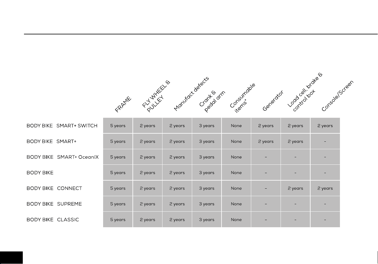
WARRANTY
Figure 1
As information to our customers we hereby outline the warranty obligations applicable to BODY BIKE
®
Indoor Cycles.
The warranty comes into force the moment the unit leaves BODY BIKE International A/S.
To get an overview see figure 1.
08

WARRANTY
09
The warranty does not cover any
accessories used together with
the BODY BIKE® Performance
Console. Data transfer between
the cycle and non-BODY BIKE®
products is not guaranteed by
any warranty.
PLEASE NOTE
All warranties are cancelled if
the console or control box has
been disassembled.
!

Warranty for the Danish manufactured BODY
BIKE® Indoor Cycle:
A two-year warranty against manufacturing
defects, excluding normal wear and tear, is given
for the flywheel and pulley. A three-year warranty is
given on the crank and the pedal arms, and a five
year warranty is given against frame breakage.
Consumable items (such as the poly V-belt, brake
pad, handlebar rubber, adjustment handles, saddle
and pedals, etc.) which are subject to continuous
wear and tear, are not covered by a warranty.
There is currently no warranty applying to the pedals.
The warranty only applies to cycles equipped with
original BODY BIKE® spare parts. All warranties are
cancelled if the cycle has been modified or in any way
not used as intended.
PLEASE NOTE
ALWAYS RELEASE TENSION AFTER USE
WARRENTY
!
In order for the warranty to be sustained, all instructions in
the respective manuals have to be followed.
This particularly relates to:
• Replacement of rubber feet on the bottom frames
once a year
• Replacement of pedals once a year and tightening of
these
• General cleaning of the bikes after use with correct
materials
• Lubrication of the adjustment handles every 3 months
• Original spare parts must be used on the bike
Warranty repairs are to be carried out by BODY BIKE In-
ternational A/S in Denmark.
At the expense of BODY BIKE International A/S.
Related freight costs are held by the customer.
Warranty spare parts are shipped ex. works.
010

ASSEMBLY
ASSEMBLY
Unpacking 12
Bottom frame 12-13
Handlebar 14
Bottle holder 14
Console 15-16
Saddle 17
Pedals 17-18
011
A fixing tool can be bought at BODY BIKE® International
A/S to ease the mounting of the bottom frame. Go to
page 38.
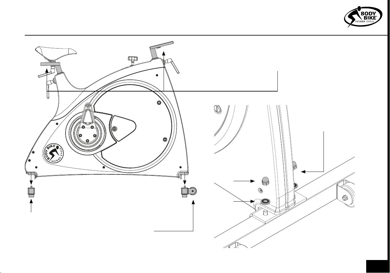
1) Arrange the bottom frames parallel on the floor
next to the cycle with the correct mounting distance
between them, see figure 3. On the front bottom
frame, the transport wheels should point forward.
2) Take hold of the front post and seat post and lift the
cycle onto the bottom frames, see figure3. Ensure that
the holes in the frame match the holes in the bottom
frames.
3) Put on the spring lock washer and the cap nut and
tighten by using a 13 mm wrench, see figure 4.
4) Unscrew the rubber feet a little. Place the cycle in
the correct position. Turn them up and down until the
cycle stands properly and it is in level.
UNPACKING BOTTOM FRAME
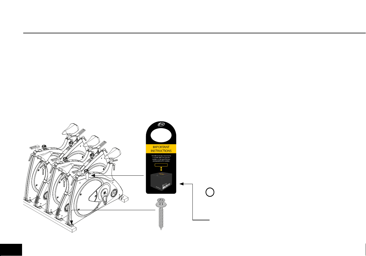
1) Open the top of the box.
2) Remove all the unmounted parts.
3) Flatten the box on the floor next to the pallet.
4) Loosen the four screws mounting the first
cycle to the pallet. See figure 2.
5) Lift the cycle off the pallet and place it on
the flattened box to spare your floor from
getting marks.
Remove all four screws
Figure 2
PLEASE NOTE
Do not overtighten the nuts. Max 12 Nm.
The cycle is precoded to a console. Match
the number on the hanger to the number
on the console box.
!
012
ASSEMBLY
BOTTOM FRAME
Figure 3
Figure 4
CAP NUT
WASHER
Front bottom
frame with
wheels pointing
forward
Tighten with
no more than
12 Nm
Back bottom
frame
LIFTING SPOTS. Be sure that the saddle
and handlebar are locked before lifting
013
HANDLEBAR BOTTLE HOLDER
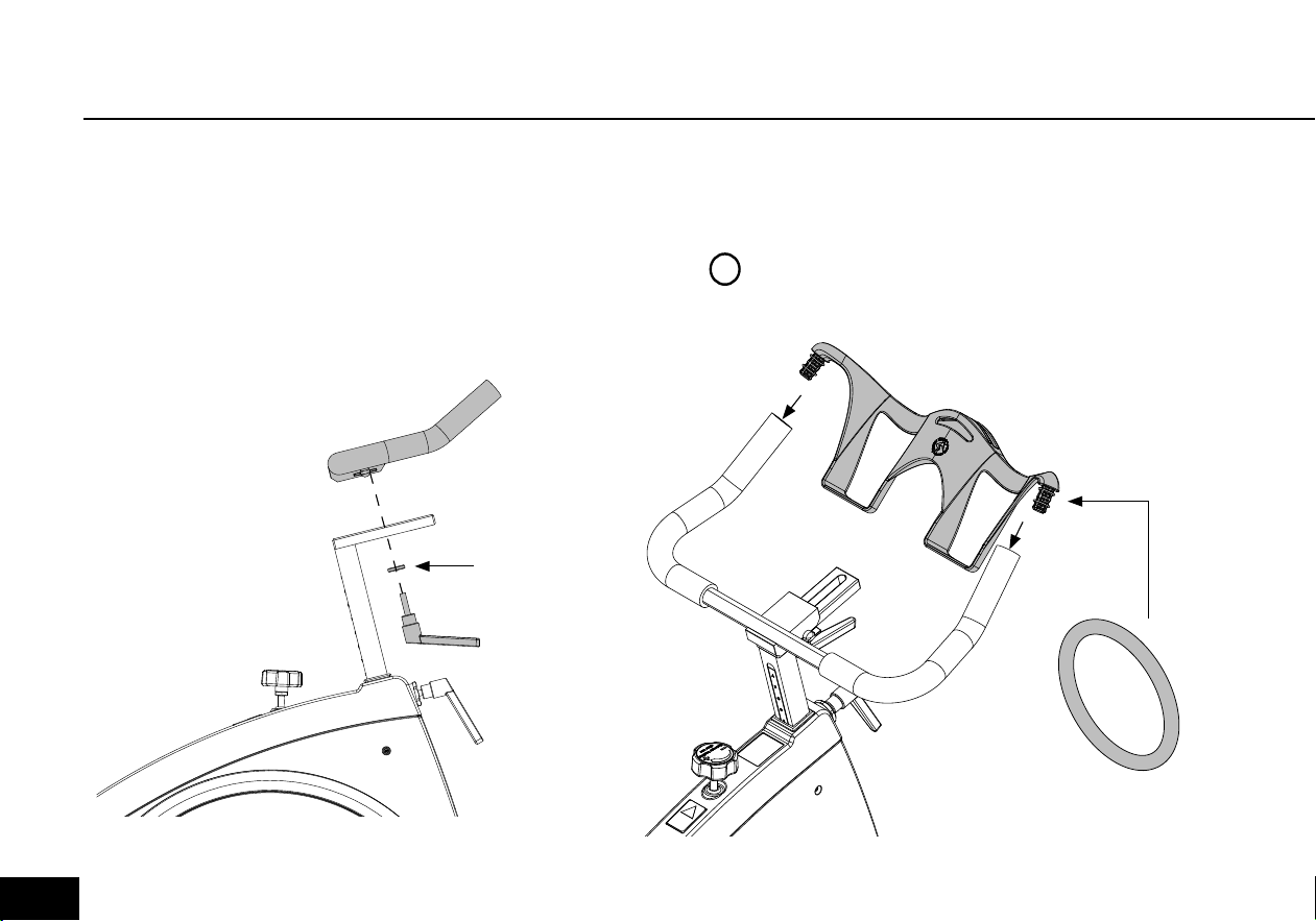
1) Place the handlebar on top of the front post.
2) Screw an adjustment handle (size 32mm)
clockwise into the socket from underneath the
post, see figure 5. Fix the handlebar completely
to the front post by tightening the adjustment
screw on the right side of the handlebar.
Mount the bottle holder at the top of the handlebar, see
figure 6. Insert the two rubber rings so the bottle holder
is firmly fixed.
Figure 6
Add 2 x on each
side
WASHER
Figure 5
PLEASE NOTE
Do not lift the bike in the Bottle Holder.
!
014
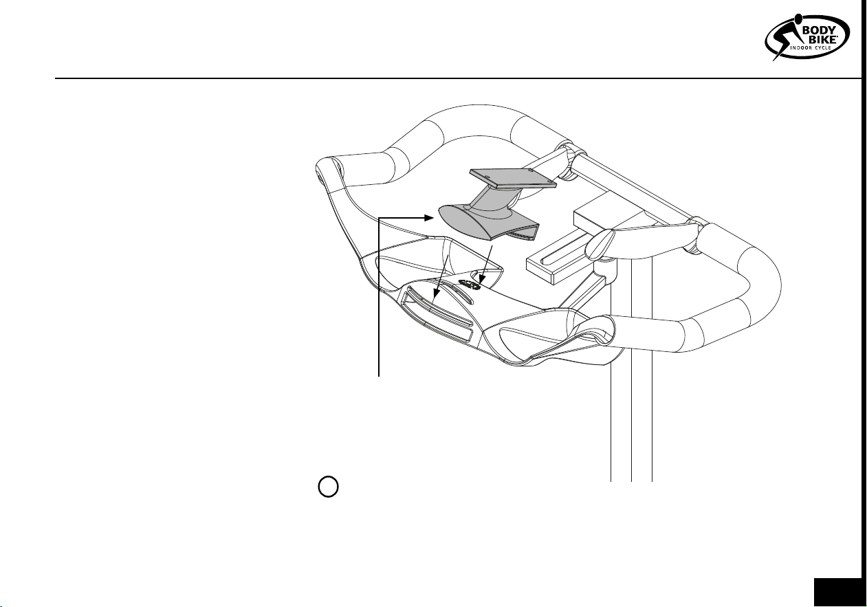
CONSOLE
1) Make sure batteries are correctly
inserted into the console. Check this
before you continue.
2) First mount the console bracket
on the bottle holder by placing the
bottom of the bracket as shown on
figure 7.
2) Press the bottom of the bracket in
place. It may be necessary to push
to fit it. Push back on the bottle
holder to counter the pressure
(figure 7).
3) Nudge the top of the bracket in
position right above the tip of the
bottle holder. Carefully press down
until it clicks. Again push back on
the bottle holder to counter the
pressure (figure 7).
4) Place the lock fitting under the
bottleholder and screw the two
stainless steel screws into the fitting
with a 3mm Allen wrench (figure 8).
PLEASE NOTE
The console is set for km and kg as default.
If preferred change to miles and lb before
mounting the console, see page 18.
!
Figure 7
ASSEMBLY
Snaps into place
015
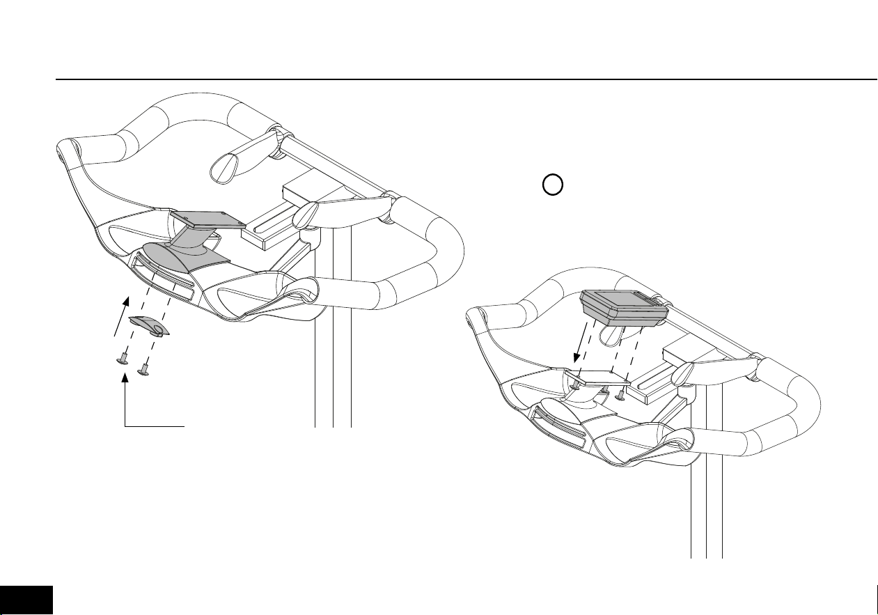
Figure 8
Figure 9
5) Place the console on the bracket - make sure that the
batteries are inserted. Screw the three black screws up into
the bracket and console using the Allen key. Keep a
hand on the console until the first screw is in to avoid it falling
off, see figure 9.
5mm Screw
PLEASE NOTE
Tighten the screws carefully
!
016
SADDLE PEDALS
ASSEMBLY
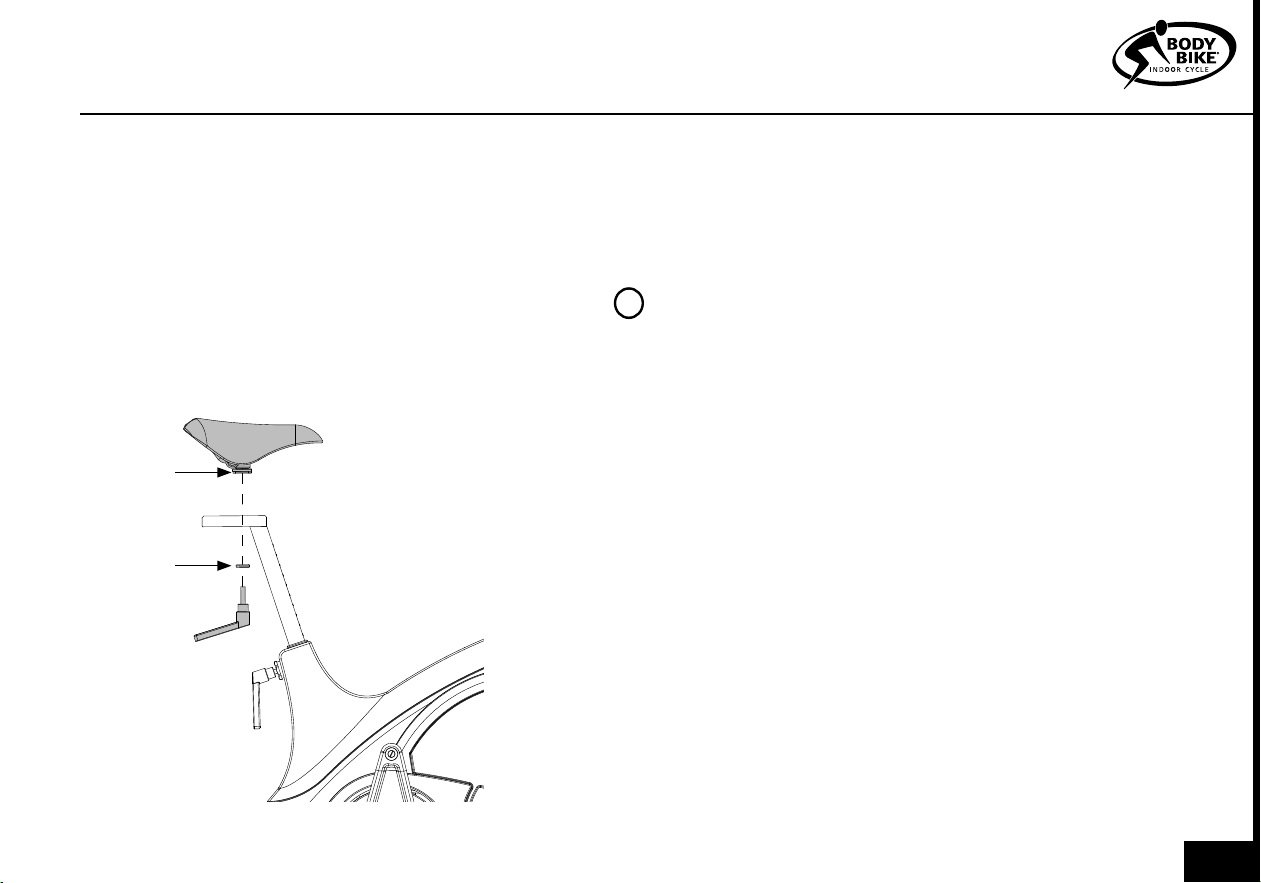
ONLY RELAVENT IF THE SADDLE IS NOT ALREADY
INSTALLED.
1) Place the saddle in the track on the seat post.
2) Secure the saddle with the remaining adjustment
handle, see figure 10.
To fasten the saddle to the adaptor and adjust the
tilt of the saddle, use a 14 mm wrench on the bolt
marked with an A on figure 10.
1) Place the right pedal arm with the socket pointing
upwards, see figure 11.
2) Put maximum resistance on the brake, so the peda-
larm is unable to rotate, see figure 12
PLEASE NOTE
The pedals are marked with R for Right and
L for Left side.
The pedals should always be screwed on in the
direction of the handlebar, see figure 13 and 14.
Make sure that the hole in the pedal arm is
greased when mounting the pedal.
Start mounting the pedal by hand as tools
will tighten the pedal at a wrong angle.
3) After tightening by hand, use a 15mm pedal wrench
to tighten the pedal completely (45Nm).
WASHER
Figure 10
A
!
017
PEDALS
Figure 11
Figure 12
Figure 13
Figure 14
Always screw
on in the
direction
towards the
handlebar
Increase the resistance of
the brake, before installing
the pedals.
018

MAINTENANCE
MAINTENANCE
Cleaning 20
Sidewards play in posts 21
Cleaning the posts 22
Adjustment handles 22-23
Replacing the brake block 23-24
Poly-V belt 25
Replace console box batteries 26
Replace console batteries 26
Resetting load cell 27
Removal of side covers 28
Using the console 29-35
019
CLEANING
After each workout, wipe the cycle down with
tissue paper.
If the cycle is covered in sweat or dirt, use water in
a spray bottle and if necessary a tissue with some
washing-up liquid.
Remember handlebar and saddle.
To make the cycle look its best, use a cloth with a
little vaseline oil on all parts except the handlebar
and saddle.
Vacuum clean the bike inside when necessary to
prevent dust from gathering on the flywheel. If dirt
has already gathered on the flywheel edge, use a
piece of rough felt to sand it down.
At an annual service check, remove the right
side cover and make sure that the small hole by
the front bottom frame is not blocked and allows
water and sweat to exit the frame, see figure 15.
Also check that the ribs on the poly-v belt and
pulley are clean. To remove the side cover go to
page 28.
Figure 15
Small drainage
hole.
Right side
cover has
been removed.
PLEASE NOTE
NEVER use alcohol or chemicals
!
020
MAINTENANCE
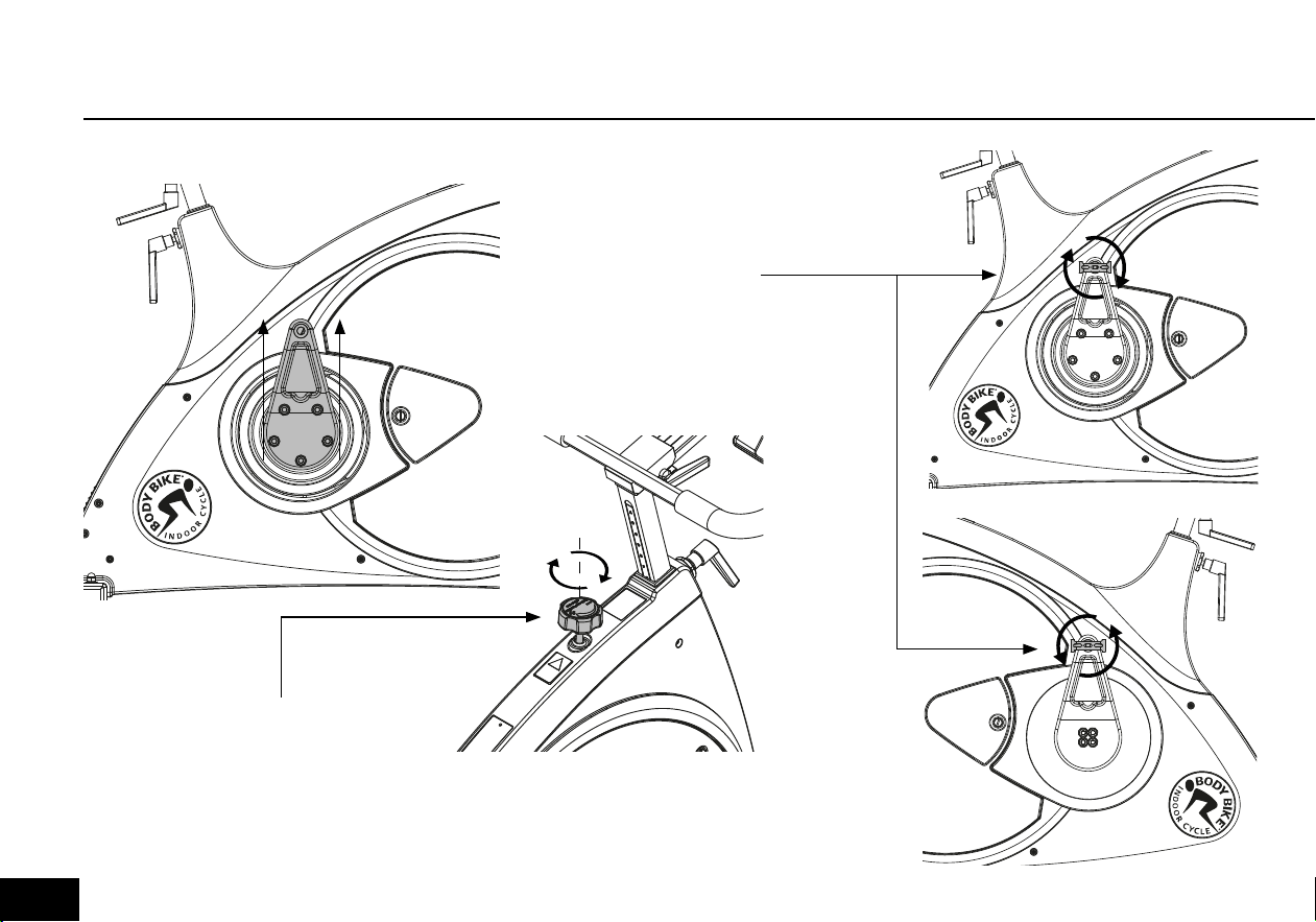
SIDEWARDS PLAY IN POSTS
Front post
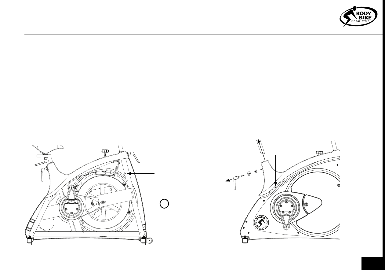
1) Remove the service hatch. See figure 20. Re-
move the right side cover by loosening the 8 bolts
by using a 3 mm Allen wrench. Go to page 28.
2) Adjust the 5x6mm pinion screw, marked S1 by
using a 2.5 mm Allen wrench, see figure 16.
Seat post
1) Remove the seat post
2) Remove the handle, the 32 mm nut and the
brass piston with a 32 mm wrench.
3) Remount the seat post
4) Carefully lift up the top cover as shown on figure
17. Adjust the right hand side screw marked S2 with a
2.5 mm Allen wrench. See figure 17.
5) Push the top cover back in place.
6) Remove the seat post and remount the brass pis-
ton, 32 mm nut and the handle
7) Remount the seat post
Figure 16
S1
S2
Figure 17
PLEASE NOTE
The adjustment has
to be very subtle in
order for the post
still to be able to
move up and down.
!
021
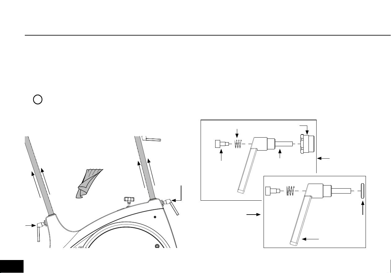
ADJUSTMENT HANDLESCLEANING THE POSTS
Every other week the posts need cleaning to protect
them from sweat etc.
Pull out the seat post and the front post and wipe
them clean with an oily cloth, see figure 18. Use
vaseline oil.
PLEASE NOTE
The posts should be cleaned every other
week to keep them in good condition
Figure 18
Created by Olena Panasovska
from the Noun Project
1x oily cloth
Every 3 months the handles need cleaning and grease to
protect the parts from sweat, dust, dirt and water.
1) Remove the adjustment handle and disassemble the
handle completely into a screw, a spring, a handlegrip,
a main screw and a brass washer, see figure 19. Do this
with both the horizontal and vertical adjustment handle.
Removing the 32mm nut is optional.
Release
Figure 19
Vertical
adjustment
Herizontal
adjustment
Washer
Screw
Main
screw
Spring
Hand grip
32mm nut
!
022
REPLACING THE BRAKE BLOCK
MAINTENANCE
2) Clean all the parts thoroughly one by one using a
steel brush. If the residue is extreme, a sharp object
can be used, for example a screwdriver.
3) Lubricate the internal parts with grease before
reassembling the handle. Remember to lubricate
inside the handlegrip as well.
4) Reassemble the handle by inserting the main screw
in the handlegrip.
5) The spring is inserted into the top of the handle and
fixed in place with the remaining screw.
6) Tighten with a 5mm Allen wrench.
7) Add grease to the main screw before mounting it
on the cycle.
PLEASE NOTE
Never use a tool when tightening
the adjustment handle on the cycle.
By pulling the handle it can be
turned freely.
!
The Kevlar® pad on the BODY BIKE® Synthetic Brake
has an expected durability of a minimum of 1500
hours, so eventually the brake pad will be worn. To
ensure that the brake pad is correctly mounted, it has
been pre-fitted to the block, and it is only possible to
purchase the complete brake block. Go to page 38.
Inspect the Kevlar brake pad after the first month
and hereafter every 3rd month. The Kevlar® brake
pad should be replaced before it is worn through and
reveal the black rubber. Go to page 38.
Figure 20
Service hatch
Lock
Lock
Lock
023
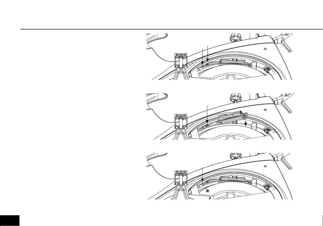
1) Remove both service hatches by loosening
the locks with a coin, see figure 20.
2) Release tension completely on the brake.
3) Remove the two screws holding the brake
block to the frame by using an 8 mm wrench,
see figure 21
4) Take the new brake block and fasten it to
the frame by tightening the screw closest to
the brake block. Then place the block in the
correct position under the brake (see figure
22).
5) Fasten the remaining screw furthest away
from the block, and then make sure that both
screws are tightened properly, see figure 23.
6) Grease should be applied to the cavity
on top of the brake block or to the top nut
on the brake to ensure a smooth interaction
between the two.
7) Remount both service hatches.
Figure 21
Figure 22
Figure 23
Remove
screws
Install and
twist
Reinstall the
last screw
REPLACING THE BRAKE BLOCK
024
MAINTENANCE
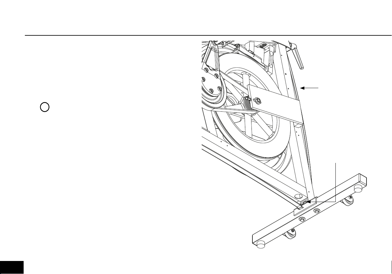
POLY-V BELT
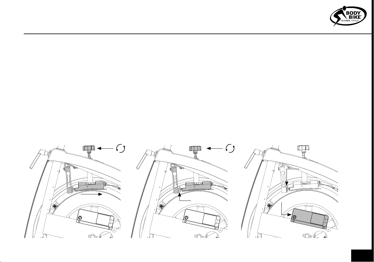
If the belt does not catch hold of the flywheel, it is time for
it to be tightened.
1) Remove the service hatch on both sides of the cycle by
loosening the three locks with a coin, see figure 20.
2) Loosen the bolts (1) on both sides of the cycle with a 19
mm wrench, see figure 24.
3) Loosen the nuts (2) on the counter bolt on both sides of
the cycle using a 10 mm wrench, see figure 24.
4) Use a 10 mm wrench to tighten the counter bolts (3). On
the right side, the tool should be pulled downwards and on
the left side upwards to tighten.
5) The belt should be tightened to approximately 125
kg/229 Hz. To measure this, a special device can be bought
at your local BODY BIKE® distributor. Go to page 28.
6) Tighten the counter bolt (2) on both sides of the cycle
again.
7) And tighten the bolt(1) again on both sides of the cycle.
8) Close the cycle by fastening the two hatches again.
PLEASE NOTE
The belt should be evenly tightened on both
sides.
The flywheel should be parallel with the long
main side member.
!
1
2
3
Figure 24
025
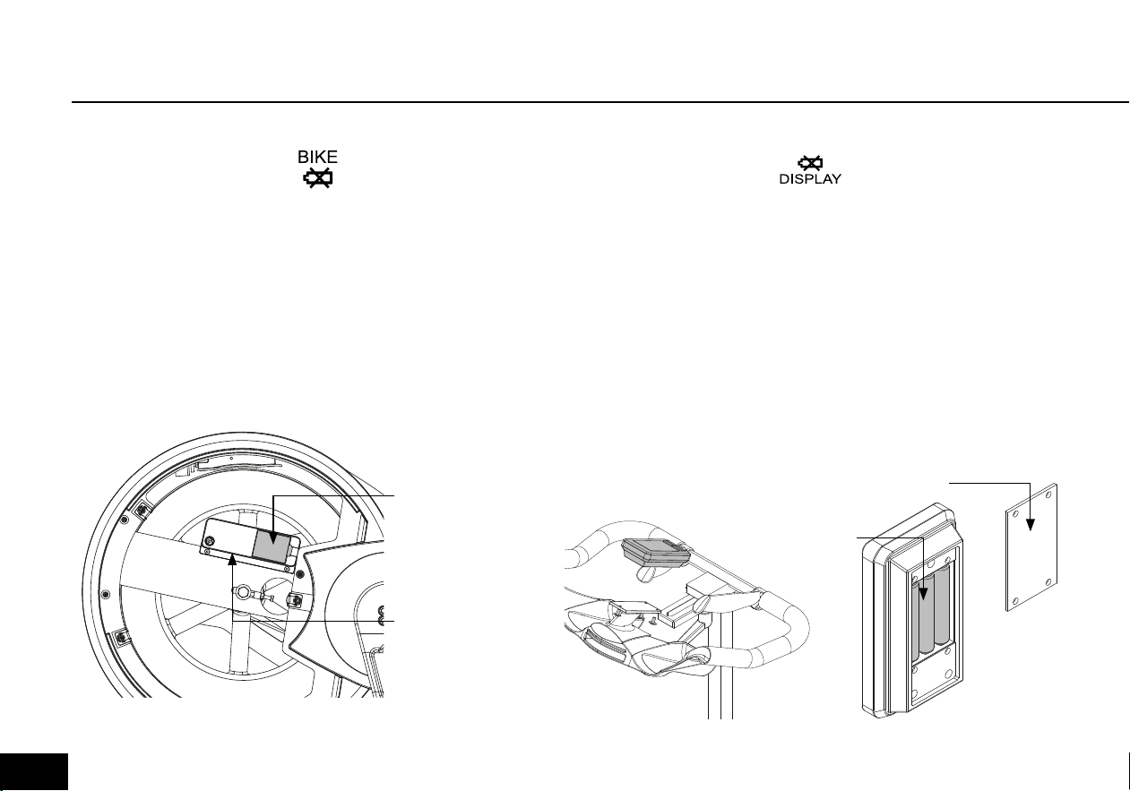
An icon lights up on the console when the display needs
fresh batteries.
1) Dismount the console from the bottleholder by removing
the three screws on the back, see figure 26.
2) Remove the battery hatch on the back of the console,
see figure 27.
3) Replace the 3 AAA batteries.
They should be minimum 1.5 V and they must not be
rechargeable.
4) Remount the battery hatch and remount the console.
See page 16.
REPLACE Console BATTERIESREPLACE CONTROL BOX BATTERIES
An icon lights up on the console when the control box
needs fresh batteries.
1) Remove the left side service hatch with a coin, see
figure 20 page 23.
2) Remove the battery hatch on the control box
and replace the three AA batteries, see figure 25.
They should be minimum 1.5V and they must not be
rechargeable.
3) Remount the battery hatch and the service hatch.
Battery hatch
Figure 27
Figure 26
AAA Batteries
Battery hatch
Figure 25
Control box
026
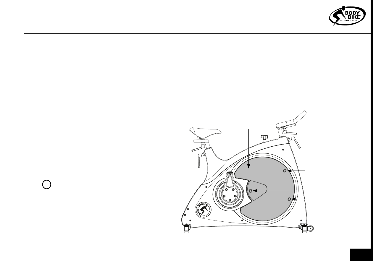
RESETTING LOAD CELL
BODY BIKE® Connect is able to
measure extremely accurate due
to the unique brake unit. When
replacing the brake unit it can be
necessary to adjust the set screw
in order to obtain full advantage of
the high level of accuracy.
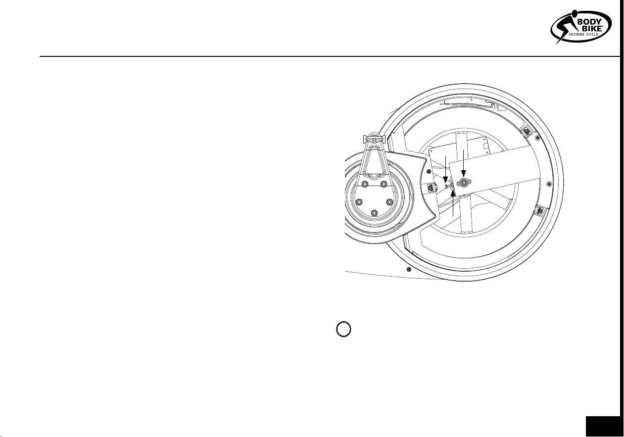
1) Remove the right service hatch,
see figure 10 on page 23.
2) Release all tension and push the
brake unit back on the shaft, see
figure 28.
3) Slowly add tension without
touching the brake unit. The brake
unit will automatically move
forward on the shaft until the brake
block arc settles on the flywheel
curvature. If the brake unit does not
move forward it has already settled
on the flywheel.
4) When the brake unit has settled,
adjust the set screw to obtain 1mm
space between the load cell and the
set screw, see figure 29. Tighten
counter nut. Move the load cell
bracket if the adjustment of the set
screw is not adequate. Be careful
not to overload the load cell by
pulling or twisting it.
5) Tighten the counter nut, see
figure 29.
6) Reset the load cell by pressing
the red reset button on the control
box, see figure 30. Make sure
nothing is pressing on the load cell
when resetting. Lastly remount the
service hatch.
Figure 28
Figure 29 Figure 30
1 mm space
Red reset button
No pressure
Move backwards
MAINTENANCE
027
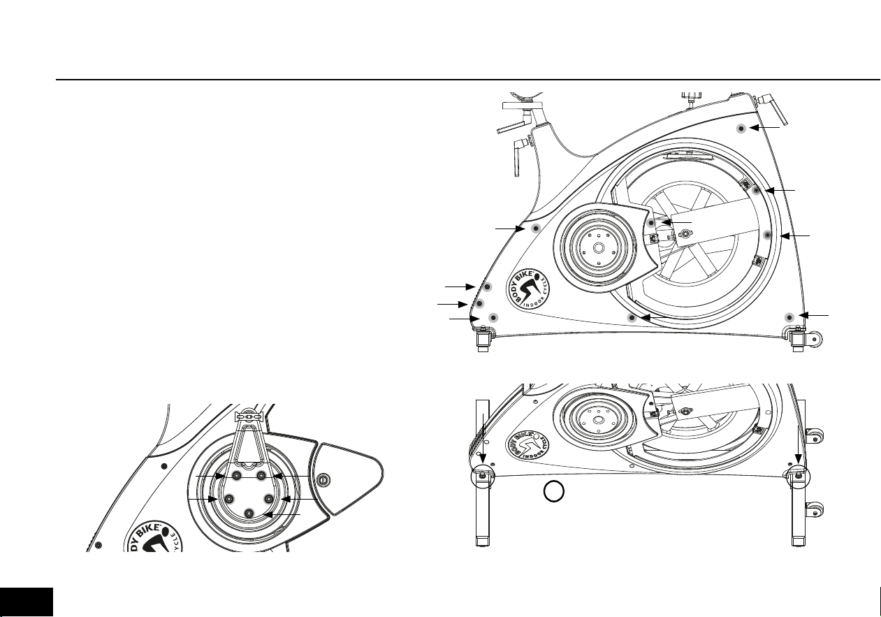
REMOVAL OF SIDE COVERS
The side covers can be removed e.g. if the belt needs to
be changed. This is technician only.
1) Dismount the right pedal arm with an 8mm Allen
wrench. See figure 31. Remove hatch. See figure 20.
2) Loosen all the screws holding the side cover with a 3
and 4 mm Allen wrench and remove them. See figure 32.
3) Dismount the top nut and washer on the bottom frame
on the right side of the cycle both in front and back with
a 13 mm wrench. See figure 33.
4) Screw the bolts down in order for the side covers to
slide past them. See figure 33.
5) Remove the side cover.
Figure 31
Figure 32
Figure 33
PLEASE NOTE
Be careful not to scratch
the side cover
!
028

USING THE Console
The console will turn ON when you
are pressing on a random key.
The console will turn OFF when you
are continually pressing E. Or no
cadence for 5 minutes.
The console will RESET when you
are continually pressing F and the
message ‘Hold to clear’ will appear.
Keep pressing the key for 5 sec
and all recorded data will be reset.
Heart rate pairing and individual
settings will be kept. This function is
useful if you have used the console
during warm-up before the actual
class starts. When turning off the
console, all data and individual
settings will be reset and the
console is ready for a new user.
and are for navigating between
screens and for adjusting values
in setting mode. Continually press
either
or to increase/decrease
rapidly.
F is for entering setting mode and
for accepting individual values. A
continued press will reset time and
data measurements.
E is for starting or pausing
time and data measurements. A
continued press will turn off the
console.
In the default settings it is possible
to change 3 settings.
• Model (Cad/Po)
• Code for control box
• Units (kg/lb, km/mi).
1) Enter default settings by taking
out the batteries and press any
button while reinserting the
batteries. A full screen display will
indicate that you have entered the
default settings. Press F to accept.
See figure 34.
ON, OFF AND RESET KEYS DEFAULT SETTINGS
PLEASE NOTE
Individual settings like age,
MHR and weight can be
changed in setting mode,
see page 32-34.
!
TIP How to enter default settings without taking out the bat-teries. 1.Turn on console 2. Go to screen 3 by pressing
3 times 3. Press E to pause the console 4. Press and hold F (do not let go) 5.
While holding F simultaneously
press and hold the other 3 buttons. Keep holding until the console displays the second screen on figure 34. You
have now entered default settings.
029
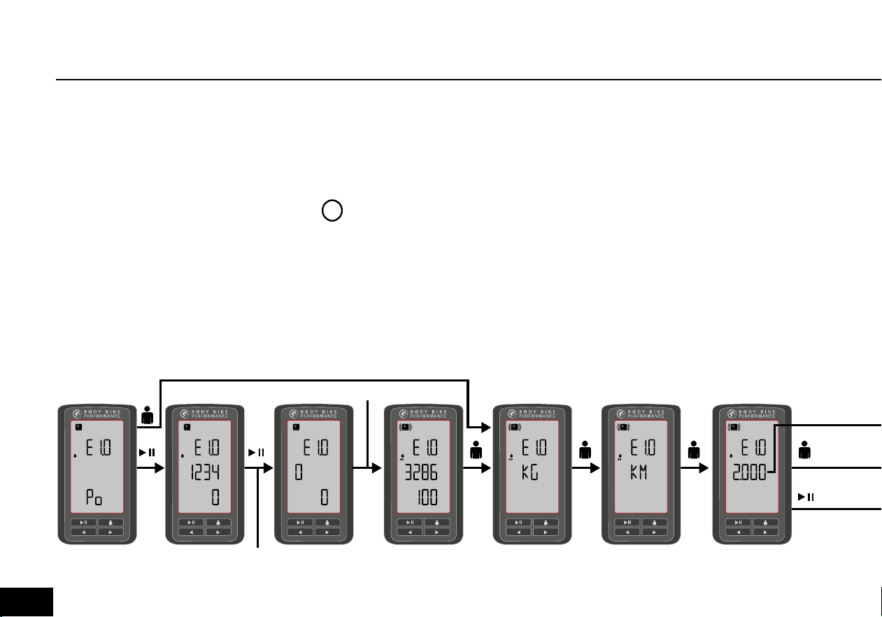
2) Choose the model Po. Use to
change. Press F to continue directly
to set units (go to step 3) or press
E to start reconnecting to the
control box. See figure 34.
For reconnecting automatically,
press E again and pedal a few
times to activate the control box.
The console will run segments until
the control box code is shown. For
reconnecting manually, continually
press E.
Use to enter code and F to
accept. The control box code is
written on the black/white label
inside the control box battery hatch.
3) Set units (kg or lb) by using . Press F to accept.
4) Set units (km or miles) by using . Press F to accept.
5) The next number shown on the display will be the load cell calibration
number. Do not change this number unless you have replaced the load cell.
Move between options by using . Accept and quit by pressing F.
DEFAULT SETTINGS
ACCEPT
ADJUST
ACCEPT
ADJUST
ACCEPT
ADJUST
ACCEPTACCEPTACCEPT
PLEASE NOTE
The console will display ‘Err’ if it is not able to leave default setting
mode because it failed to connect to the control box. Make sure the
control box code is correct and pedal a few times to activate the control
box.
You can retain the load cell calibration number from BODY BIKE® if
necessary. Please write an email to info@body-bike.com and state the
bike’s serial number (on the metal plate on the top cover) and the two
numbers on the right side of the load cell.
!
Figure 34
PRESS E FOR AUTO SEARCH
LONG PRESS E FOR MANUAL
PEDAL
030

USING THE Console
INDIVIDUAL LOAD CELL NO. DO NOT CHANGE.
END DEFAULT SETTING MODE
CHANGE LOAD CELL CAL. NO. (ONLY WHEN REPLACING LOAD CELL)
Heart rate
The BODY BIKE® Performance
Console is able to receive data
from several brands of heart rate
transmitters. Some connections
may be more fragile than others.
Move the bikes further apart if you
experience crosstalk. BODY BIKE®
recommends use of an ANT+ heart
rate transmitters. Make sure you
are the one closest to the console
when pairing.
Weight
Units (kg/lb) can be set in default
setting mode, see page 29-30.
Your weight together with your work
load is used for calculating calories.
Age or MHR
Enter maximum heart rate if you
know it. Otherwise enter age and
your maximum heart rate will be
calculated from your age (220 -
age). Your MHR is used to determine
%MHR.
Watt level test
Relative VO2 max and %MAX WATT
If you do not know your relative VO2
max, you can take the watt level test
to determine it. The test will reveal
your watt level and from this the
relative VO2 max is calculated. The
relative VO2 max is an expression of
your oxygen consumption in relation
to your body weight. The watt level
is used to determine %MAX WATT.
Many instructors use the %MAX
WATT to guide a class because it is
relative to what each participant is
able to perform. If you feel the level
is too high or too low, adjust your
watt level in user settings, see page
33-34. A high watt level means you
will have to work harder to obtain
a certain %MAX WATT than if you
choose a lower watt level. Adjust
the watt level according to your
physical state.
Default user values
If you start pedaling without
entering your individual values, the
default settings will be used.
The default setting are:
Age or MHR - 30 or 190bpm.
Weight - 70kg or 154lb.
Relative VO2 max - 35.
TIPS AND INFORMATION
031
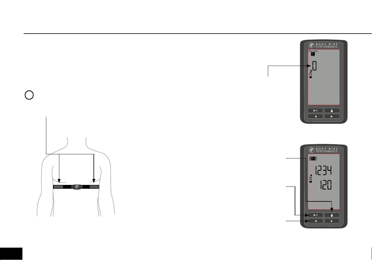
2) Press F to enter setting mode.
3) If there is no heart rate
transmitter paired, the pairing will
start automatically and the display
will look like figure 36. If a heart
rate transmitter is already paired,
the display will look like figure 33.
Press F to maintain this pairing and
continue to next setting, see figure
41, or press or to start new
pairing.
4) Lean forward to get your heart
rate transmitter as close to the
bottom of the console as possible.
The display will run segments in 0
shapes until the code is registered.
When the pairing is finished the
display will look like figure 37. Press
F to maintain this pairing and
continue to next setting. Press or
to start new pairing.
1) Put on your heart rate transmitter,
see figure 35. The belt should
be worn tight without causing
discomfort. The electrodes must be
moist and be placed just below the
chest muscles.
HEART RATE
Figure 35
PLEASE NOTE
Electrodes facing inwards
in contact
!
CODE
HR PAIRING
PAUSE
ACCEPT
ADJUST
QUIT
HR PAIRING
PAUSE
ACCEPT
ADJUST
QUIT
CODE
HR PAIRING
PAUSE
ACCEPT
ADJUST
QUIT
HR PAIRING
PAUSE
ACCEPT
ADJUST
QUIT
Running
segments
until pairing
is complete
Figure 36
Figure 37
Press F to
accept and
continue
Press E to
accept and
end
Press or
to start new
pairing
032
USING THE Console
Press F to enter setting mode.
If you are wearing a heart rate
transmitter, follow the guidance
on page 32 to pair it. If not, press
F to continue without heart rate
transmitter. Enter your age or MHR
and weight as described on figure
38.
AGE, HMR AND WEIGHT
Press E to
accept and
end setting
mode
Press F to
accept and
continue to
next setting
Press or
to increase/
decrease
Figure 38
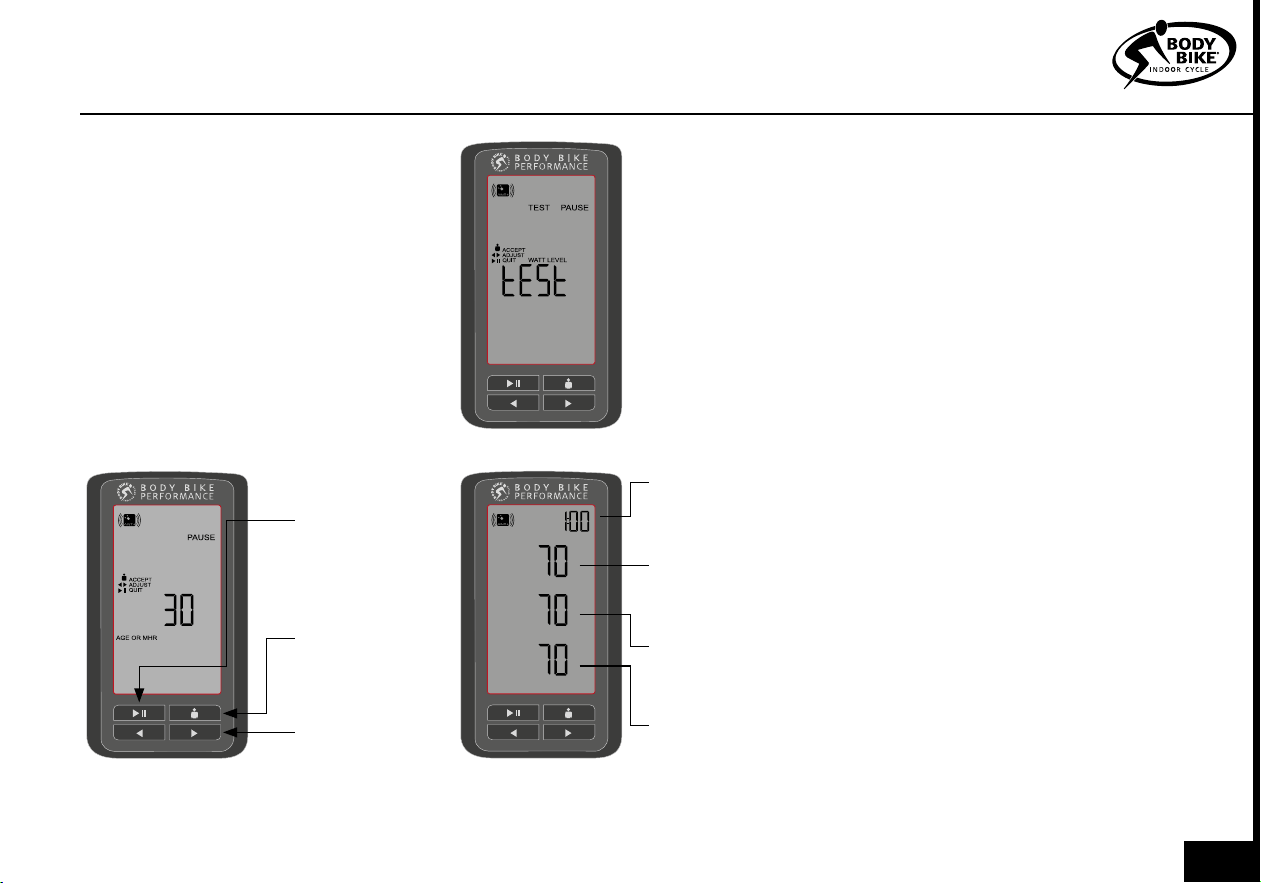
If you already know your relative
VO2 max, use the arrows to enter
it and press F or
E to accept and
end setting mode. If you do not
know it, you can do a watt max test.
Please follow the guide below.
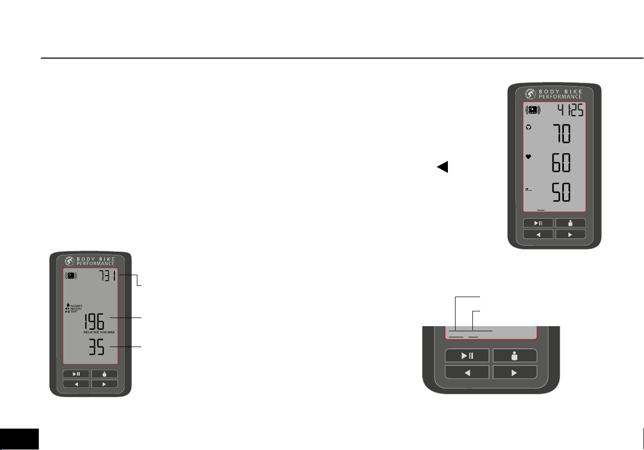
1) Gently warm up for 5-10 min.
2) Enter the test by pressing F until
you reach the test screen, see figure
39.
3) Press F again to start the test.
4) The top figure is your cadence.
This should be as close to 70 as
possible, see figure 40.
5) The middle figure is the watt
you need to attain and the bottom
figure is how many watt you are
currently performing, see figure 40.
Adjust the tension until you attain
the watt prescribed in the middle
figure. The arrows at the bottom
left of the screen will tell you if you
need to add more tension or release
tension.
WATT TEST
RPM
WATT LEVEL
WATT
TEST
Time left on
this level
Your current
cadence
The watt
you must
attain
Your current
watt
Figure 39
Figure 40
033
6) Every 2 minutes, the watt will
increase by 35 watt. Adjust tension
to match again. You can follow the
time in the top right corner of the
display, see figure 40.
7) Continue until you are unable to
progress further. Press any button
to end test. The display will show
your relative VO2 max and your
watt level, see figure 41. Press F or
E to accept and end or use
to adjust.
WATT TEST
WATT LEVEL
PAUSE
Total test time
Your Watt
level
Your relative
VO2 max
NAVIGATION AND SCAN
The navigation line at the bottom
of the screen will show you what
screen you are on and if you are
in scan mode. In scan mode the
console automatically changes
between the first two screens. The
console is in scan mode when the
line underneath the word ‘scan’ is
on and the line above ‘scan 1 2’ is
on. A line will also appear under the
screen number which is currently
shown, see figure 43.
End scan mode:
Press
or and the console will
end scan mode.
takes you to
screen 1 and
takes you to screen
5, see figure 46.
Enter scan mode:
Keep pressing
or until the line
under ‘scan’ turns on, see figure 42.
Navigate between screens:
Use
or , see figure 42.
RPM
%
MAX
HR
HR
2 3 4 51SCAN
The console is in scan
mode on screen 1
2 3 4 51SCAN
RPM
%
MAX
HR
%
MAX
WATT
SCAN
MODE
Figure 41
Figure 42
Figure 43
034
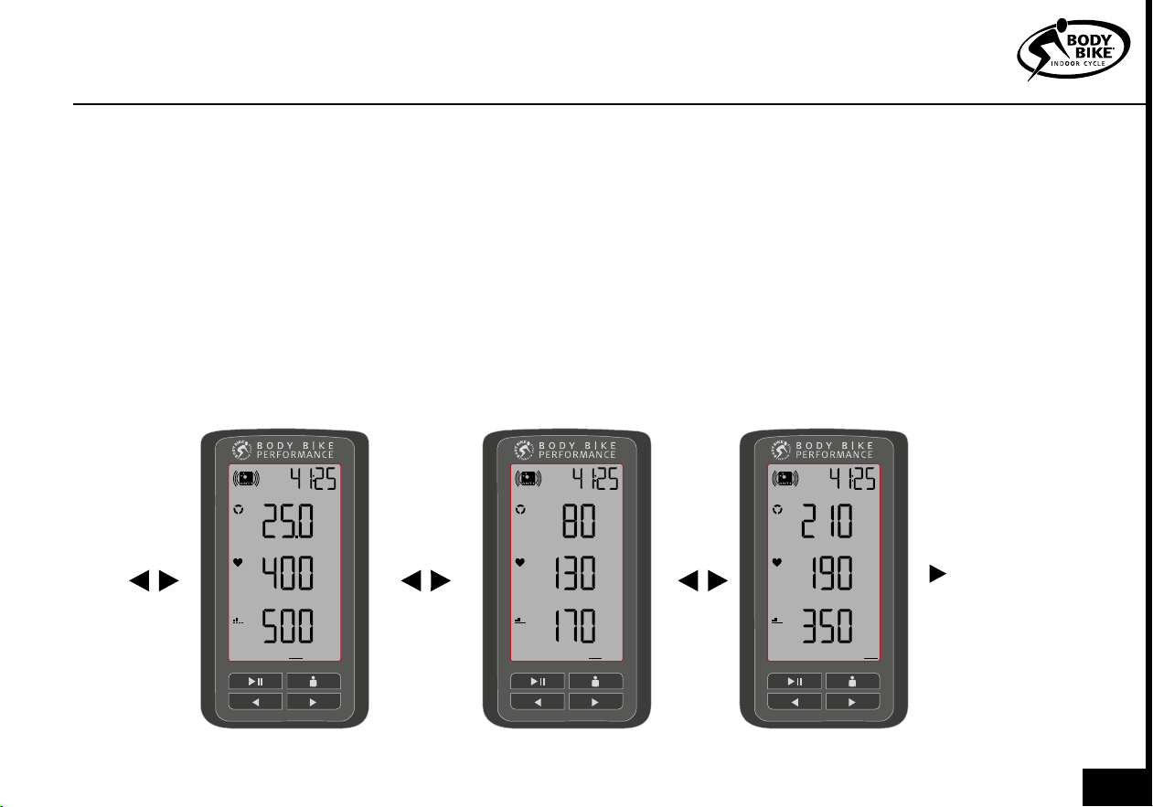
Screen 1
[RPM, %MAX HR, %MAX WATT] The
screen shows the values relative to
your maximum values. This is the
data you will most likely use during
training.
Screen 2
[RPM, HR, WATT] This screen holds
the absolute values.
Screen 4
[RPM AVG, HR AVG, WATT AVG]
Screen 4 holds average values
accumulated from all data col-
lected throughout the workout.
Screen 5
[MAX RPM, MAX HR, MAX WATT]
Screen 5 shows the maximum
values you have reached during
the workout. Do not pedal
uncontrollably fast or hard in an
attempt to break a record.
Screen 3
[Km/Mi, Kcal/Hr, Kcal]
This is a summary screen with your
total distance at the top and your
total burned kilocalories at the
bottom. Both the distance and the
calories are based on watt. The
middle figure is KCAL/HR. It is an
expression of how hard you are
working right now and tells how
many kilocalories you will burn if
you keep up the current pace and
tension for an hour.
2 3 4
5
1SCAN
KM
KCAL/
HR
KCAL
2 3 4
5
1SCAN
RPM
AVG
HR
AVG
WATT
AVG
2 3 4
5
1SCAN
MAX
RPM
MAX
HR
MAX
WATT
SCAN
MODE
USING THE Console
Figure 44 Figure 45 Figure 46
035

TROUBLESHOOTER
1) The bike is showing an uneven watt output?
In most situations, an uneven watt output is due to a
dirty flywheel and brake pad. This needs to be main-
tained in order to keep up a smooth ride. Resetting
the loadcell can also help in some situations. Go to
page 27.
4) How do I replace batteries?
Over time you will have to change the batteries in
both the console and control box. This is quite simple.
Go to page 26 and follow the instructions.
3) How to get rid of horizontal movement in the
saddle and steer?
If the front sled or saddle sled begins to slide forward
even though they are locked by the smart handles, it
is time to tighten them up Go to page 14 and 17 and
follow the instructions. Remember, do not overtight-
en. Everybody needs to be able to adjust the bike.
6) Does the warranty cover me?
If something on your bike breaks it is always a good
idea to check if it is covered by the warranty. Go to
page 8 and 10. This gives you the overview that you
need. If the warranty covers the damage then go to
Page 38.
2) How to get rid of downwards movement in
the saddle and steer?
If the front post or saddle post begins to slide down
even though they are locked, it is time to tighten them
up. Go to page 21 and follow the instructions. Re-
member, do not overtighten.
5) How to pair the console with my Heartrate
monitor?
This operation is simple. Just follow the instructions
on page 32. Connecting an HRM to the console will
happen automatically if it has been connected be-
fore. We recommend a waist HRM because it is the
most precise compared to other types eg. wrist.
036

TROUBLESHOOTER
TROUBLESHOOTER
7) How do I perform a VO2 max test?
If you don’t know your relative VO2 MAX, it will be a
good idea to perform a test. Go to page 33-34 and
follow the instructions. Remember to warm up before
you do the test.
10) Any good daily advice to keep the cycles in
a good condition?
It is not only important to follow the maintenance
but also very important to treat the bike well in every-
day use. This keeps the bikes in a good condition.
Go to page 7 and make sure that this is respected in
daily use.
9) What is the durability of the brake block?
It is expected that the durability of the brake block is
minimum 1500 hours. This can vary depending on the
power applied. Go to page 23 and check if it is time to
replace your brake block.
8) The poly-v belt doesn’t grip properly in the
flywheel?
This can easily be fixed. Go to page 25 and follow
the instructions. But do not perform this action if you
don’t have the necessary tools.
037

ONLINE INFORMATION
Need any spare parts?
If you need any spare parts for your bike, follow the link below and choose your location.
You will then get the direct contact information for your local distributor.
https://body-bike.com/distributors-search/
Need more information?
Wanna know more about your BODY BIKE Supreme, follow the link below.
https://body-bike.com/indoor-bikes/body-bike-connect/
Need online support?
If you have any questions, problems or anything else regarding your BODY BIKE,
you are welcome to contact us on the mail below.
info@body-bike.com
Looking for another bike?
Take a look at our collection.
We provide a wide range of bikes and customization.
Follow the link below.
https://body-bike.com/category/indoor-bikes/
038

INDEX
Adjustment handles 7, 10,22
Adjustment screw 14
Assembly 11-18
Belt 10, 25
Bottom frame 12-13
Bottle holder 14
Brake 7, 10, 23
Cleaning 4, 20, 22
Cover 28
Crank, warranty 8
Frame 10, 12, 13
Grease 17, 22, 24
Handle 10, 22
Handlebar 14
Height 6
Information, general 7
Length 6
Maintenance 19-28
Manufacturer 6
Mounting 12-13
Patent 6
Pedal 17-18
Poly V-belt 25
Post (front and seat) 22
Product description 6
Rubber feet 7, 12
Saddle 17
Side cover 28
Tools 3
Trouble shooter 36-37
User weight 6
Wear and tear 10
Weight 6
Width 6
Wheel 9
039

BODY BIKE
®
International A/S
Niels Bohrs Vej 2
DK-9900 Frederikshavn
Denmark
Phone: +45 9843 9696
www.body-bike.com
Edition 5.0