01
INSTRUCTIONS
BODY BIKE
®
INDOOR CYCLE
BODY BIKE
®
SMART+
ENGLISH

Equipment required 2
Introduction 3
Specifications 4
General information 4
Certification 5
Warranty 6-7
Assembly
Unpacking 9
Bottom frame 9-10
Handlebar 11
Bottleholder 11
Saddle 12
Pedals 13-14
Maintenance
Adjustment handle horizontal 16-17
Adjustment handle vertical 18
Cleaning the flywheel 19
Cleaning the brake 19
Removal of side covers 20-21
Service hatch 22
Replacing the brake block 22-23
Poly-V belt 24
Posts 25
Control box 26-27
Support
Troubleshooting 28-29
Online information 30
Index 31
TABLE OF CONTENTS
Unpacking
Drill bit
Drill
Bottom frame
5 mm Allen wrench
Saddle
14 mm wrench
Pedals
15mm pedal wrench
Grease
Cleaning
Tissue paper or cloth
Spray bottle with water
Soap (only washing-up liquid)
Vaseline oil
Consol Box
3mm Allen Wrench
Post cleaning
Cloth
Vaseline oil
Adjustment handle
6mm Allen Wrench
5mm Allen Wrench
3mm Allen Wrench
Screwdriver
Brake block
8 mm wrench
Poly-V belt
10 mm Allen wrench
19 mm wrench
Measuring device
Screwdriver
Side covers
3 mm Allen wrench
EQUIPMENT REQUIRED
02
This manual provides information on the assembly
and maintenance of the BODY BIKE® indoor cycle.
The manual is intended for the owners and service
people responsible for cleaning and maintenance.
Before assembling the cycle, please read the manual
and prepare the correct tools, see equipment
required page 2. When assembling the cycle, we
recommend that you follow the manual step by step.
Maintaining the cycle is very important. In the manual, you
will find clear instructions on how to maintain the cycle.
Over time it will be necessary to replace worn-out parts.
You will find a detailed description and exploded drawings
of BODY BIKE®’s spare parts on our website www.body-
bike.com. When ordering spare parts from the local BODY
BIKE® distributor, please refer to the item number (P/N no.)
in order to make sure you will receive the correct spare part.
We recommend that you order original parts, accessories
and materials necessary for the maintenance of
the cycle at your local BODY BIKE® distributor.
For further information on accessories, please check our
website www.body-bike.com
INTRODUCTION
03

Manufacturer:
BODY BIKE® International A/S
Niels Bohrs Vej 2
DK-9900 Frederikshavn
Denmark
Phone: +45 9843 9696
Weight:
Assembled: 64 kilogram
Packed weight(5 cycles): 350kg
Length, Width, Height:
Assembled size:
106cm, 56cm, 99cm
Packed size (5 cycles):
120cm, 80cm, 114cm
Maximum user weight
150 kg (Please note that the
max. pedal load may be lower)
Patent held for:
Crank system
Materials
Cast iron
Stainless steel
Plastic (ABS) covers
High quality bearings
Frame: Robot-welded, fully
galvanized, powder coated and
hardened
Anodized aluminum
Wipe off the cycle after EVERY use.
ALWAYS loosen all handles
and release tension after use.
The rubber feet should always be adjusted to
ensure that the cycle is in level.
Every other year the rubber feet should be
replaced as the rubber hardens and becomes
unable to absorb the impact.
Tighten up the pedals every 14 days or every month to avoid
them getting loose or breaking off. Pedals and adjustment
handles should be changed once a year.
DO NOT perform stretch exercises on the cycle, pedals or up
against the cycle, except against the stretch area at the rear end
of the cycle.
DO NOT switch the front or seat post from one cycle to another.
DO NOT lift the cycle by the saddle.
GENERAL INFORMATION
SPECIFICATIONS
PLEASE NOTE
ALWAYS RELEASE
TENSION AFTER USE
!
04

Federal Communication Commission In-
terference Statement
This equipment has been tested and
found to comply with the limits for a Class
B digital device, pursuant to Part 15 of
the FCC Rules. These limits are designed
to provide reasonable protection against
harmful interference in a residential in-
stallation. This equipment generates,
uses, and can radiate radio frequency
energy and, if not installed and used in
accordance with the instructions, may
cause harmful interference to radio com-
munications. However, there is no guar-
antee that interference will not occur in a
particular installation. If this equipment
does cause harmful interference to ra-
dio or television reception, which can be
determined by turning the equipment off
and on, the user is encouraged to try to
correct the interference by one or more
of the following measures:
•Reorient or relocate the receiving anten-
na.
• Increase the separation between the
equipment and receiver.
• Connect the equipment into an outlet
on a circuit different from that to which
the receiver is connected.
• Consult the dealer or an experienced
radio/TV technician for help.
FCC Caution:
This device complies with Part 15 of
the FCC Rules. Operation is subject to
the following two conditions:
(1) This device may not cause harmful
interference, and (2) this device must
accept any interference received, in-
cluding interference that may cause
undesired operation.
EU Declaration of Conformity
This device complies with the essential
requirements of the Radio Equipment
Directive, RED 2014/53/EU. The fol-
lowing test methods have been ap-
plied in order to prove presumption of
conformity with the essential require-
ments of the RED 2014/53/EU:
EN60950
EN61000-6-2
EN61000-6-3
EN 55022+EN 55024(2010)
EN 301 489-1 V1.8.1(2008-04)
EN 301 489-3V1.4.1(2002-08)
EN 300 440-2 V1.3.1(2009-03)
This device is a 2.4 GHz wideband
transmission system (transceiver),
intended for use in all EU member
states and EFTA countries, except in
France and Italy where restrictive use
applies.
In Italy the end-user should apply for a li-
cense at the national spectrum authorities in
order to obtain authorization to use the de-
vice for setting up outdoor radio links and/or
for supplying public access to telecommuni-
cations and/or network services.
This device may not be used for setting up
outdoor radio links in France and in some ar-
eas the RF output power may be limited to
10 mW EIRP in the frequency range of 2454
– 2483.5 MHz. For detailed information the
end-user should contact the national spec-
trum authority in France.
Hereby, BODY BIKE, declares that the BODY
BIKE SMART+ is in compliance with the es-
sential requirements and other relevant pro-
visions of RED 2014/53/EU.
ANT+ and Bluetooth
The SMART+ control box is compatible with
BLE/Bluetooth Smart and ANT+ certified.
CERTIFICATION
05
®
®
®
®
SMART
®
®
®
WARRANTY
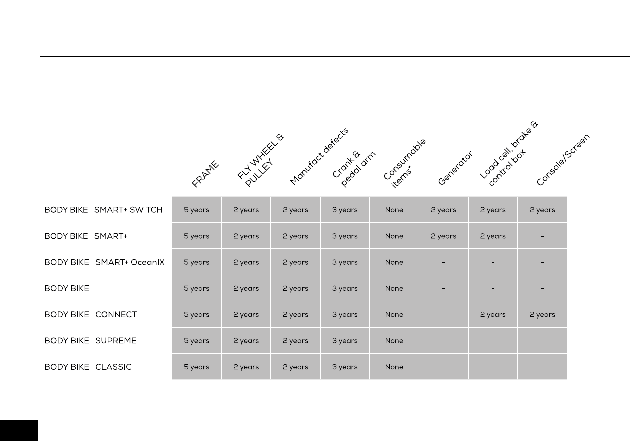
Figure 1
As information to our customers we hereby outline the warranty obligations applicable to BODY BIKE
®
Indoor
Cycles. The warranty comes into force the moment the unit leaves BODY BIKE International A/S.
To get an overview see figure 1.
06

WARRANTY
Warranty for the Danish manufactured BODY
BIKE® Indoor Cycle:
A two-year warranty against manufacturing
defects, excluding normal wear and tear, is given
for the flywheel and pulley. A three-year warranty is
given on the crank and the pedal arms, and a five
year warranty is given against frame breakage.
Consumable items (such as the poly V-belt, brake
pad, handlebar rubber, adjustment handles, saddle
and pedals, etc.) which are subject to continuous
wear and tear, are not covered by a warranty.
There is currently no warranty applying to the pedals.
The warranty only applies to cycles equipped with
original BODY BIKE® spare parts. All warranties are
cancelled if the cycle has been modified or in any way
not used as intended.
In order for the warranty to be sustained, all instructions in
the respective manuals have to be followed.
This particularly relates to:
• Replacement of rubber feet on the bottom frames
once a year
• Replacement of pedals once a year and tightening of
these
• General cleaning of the bikes after use with correct
materials
• Lubrication of the adjustment handles every 3 months
• Original spare parts must be used on the bike
Warranty repairs are to be carried out by BODY BIKE In-
ternational A/S in Denmark.
At the expense of BODY BIKE International A/S.
Related freight costs are held by the customer.
Warranty spare parts are shipped ex. works.
PLEASE NOTE
All warranties are cancelled if
the control box has been disas-
sembled.
!
07

Unpacking 9
Bottom frame 9-10
Handlebar 11
Bottleholder 11
Saddle 12
Pedals 13-14
ASSEMBLY
08
1) Open the top of the box.
2) Remove all the unmounted parts.
3) Flatten the box on the floor next to the pallet.
4) Loosen the two screws mounting the first cycle to
the pallet. See figure 2
5) Lift the cycle off the pallet and place it on the flat-
tened box to spare your floor from getting marks.
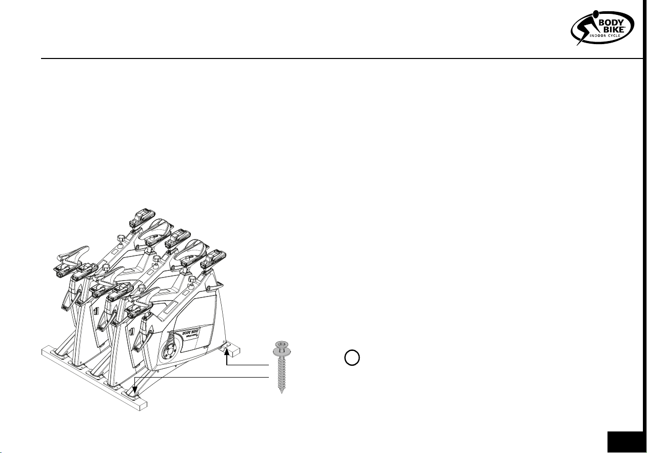
UNPACKING
Figure 2
A fixing tool can be bought at BODY BIKE®
International A/S to ease the mounting of the bottom
frame. Go to page 30.
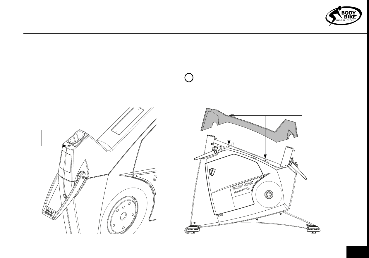
1) Arrange the bottom frames parallel on the floor
next to the cycle with the correct mounting distance
between them, see figure 3. On the front bottom
frame, the transport wheels should point forward.
2) Take hold of the front post and seat post and lift
the cycle onto the bottom frames, see figure 3. Ensure
that the holes in the frame match the holes in the
bottom frames.
3) Put on the spring lock washer and the 8mm bolt
and tighten by using a 5 mm Allen wrench, see figure
4.
4) Unscrew the rubber feet a little. Place the cycle in
the correct position. Turn them up and down until the
cycle stands properly and it is in level.
BOTTOM FRAME
PLEASE NOTE
Do not overtighten the nuts. Max 12 Nm.
!
ASSEMBLY
09
BOTTOM FRAME
Figure 3
Figure 4
Front bottom
frame with wheels
pointing forward
Back bottom frame
LIFTING SPOTS. Be sure that the saddle
and handlebar are locked before lifting
8mm Bolt
WASHER
Tighten with no
more than 12 Nm
Do not lift in the
saddle
010
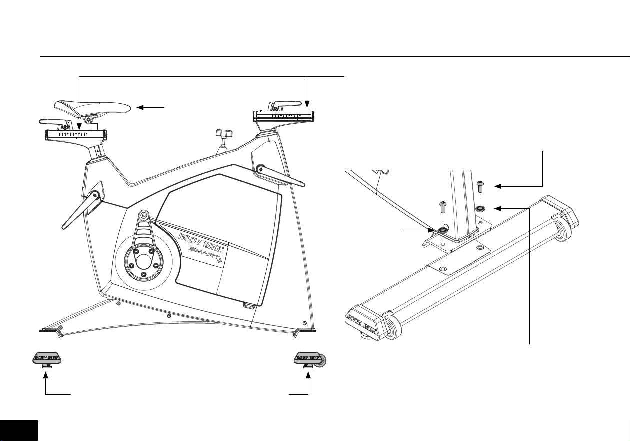
1) Release the front sled and pull it al the
way backwards.
2) Place the handlebar on top of the front
sled as shown in figure 5.
3) Screw a 4mm bolt into the sled from be-
low. Remember to use a washer in between
as shown in figure 5. Tighten with no more
than 8 Nm.
HANDLEBAR
Figure 5
ASSEMBLY
BOTTLEHOLDER
PLEASE NOTE
Make sure the
handlebar is stable.
!
1) Grab the bottleholder and install two o-rings on each
side.
2) Press the bottleholder into the steer as shown in figure
6. Make sure that the o-rings stay in place.
WASHER
BOLT 4mm
O-RING
PLEASE NOTE
Do not lift the bike in the bottleholder
!
Bottleholder
011
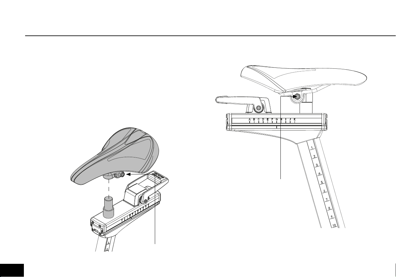
SADDLE
ONLY RELEVANT IF THE SADDLE IS NOT ALREADY
INSTALLED.
1) Place the saddle on top of the cylinder.
2) Secure the saddle by tightening the bolt. Adjustment and
tilt can be done before it’s completely fixed.
ADJUSTMENT BOLT
Figure 6
ADJUSTMENT BOLT
Figure 7
012
ASSEMBLY
PEDALS
1) Place the right pedal arm with the socket
pointing upwards, see figure 9.
2) Put maximum resistance on the brake, so the
pedal arm is unable to rotate, see figure 8.
Please note
The pedals are marked with R for Right and L
for Left side.
The pedals should always be screwed on in the
direction of the handlebar, see figure 10 and 11.
Make sure that the hole in the pedal arm is
greased when mounting the pedal.
Start mounting the pedal by hand as tools will
tighten the pedal at a wrong angle.
3) After tightening by hand, use a 15mm ped-
al wrench to tighten the pedal completely
(45N/4,5kg).
!
Figure 8
Clockwise will increase
the resistance
Counterclockwise will
loosen the resistance
013
Figure 9
Figure 10
Figure 11
Tighten in the direction
of the handlebar
Point upwards
014

MAINTENANCE
Adjustment handle horizontal 16-17
Adjustment handle vertical 18
Cleaning the flywheel 19
Cleaning the brake 19
Removal of side covers 20-21
Service hatch 22
Replacing the brake block 22-23
Poly-V belt 24
Posts 25
Control box 26-27
MAINTENANCE
015
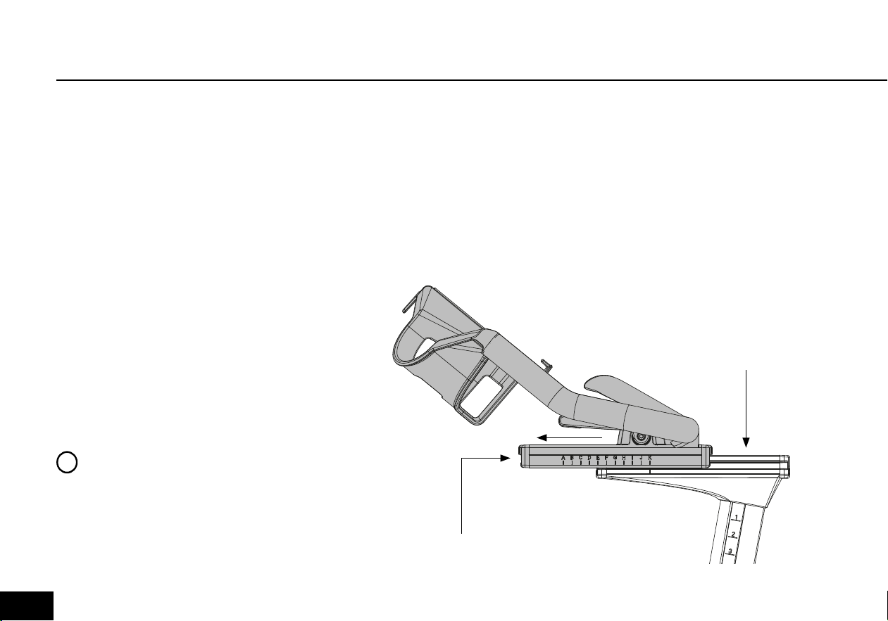
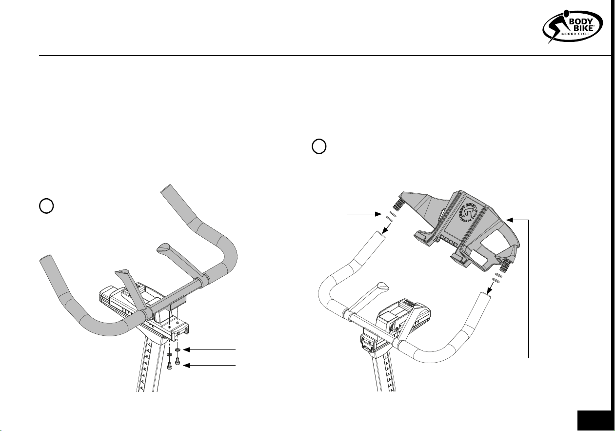
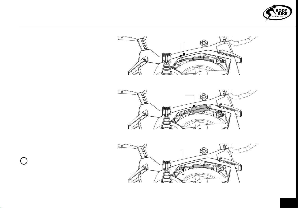
Every 3 months the handles need
cleaning and vaseline oil to protect
the parts from sweat, dust, dirt, salt
and water.
1) Remove the front end-cap bye
releasing the two 4mm bolts. See
figure 11
2) Release resistance and push the
sled forward. The letter
K Should be
above the line as shown in figure 11.
3) Unscrew the 8mm bolt from
below. This enables you to slide off
the handlebar from the sled. See
figure 11.
4) Remove the handlebar, 8mm
bolt, brake plate and plastic tube.
See figure 13
5) Clean every part if necessary.
Clean also inside the aluminum
sled. Do not use any kind of grease
inside the sled.
6) Check if the brake plate and 8mm
bolt are fine. If not replace
these parts.
7) This is optional. Use vaseline
oil on top of the front post sled.
Apply sparingly.
8) Reassemble the slep by
pushing the brake plate into
the front post alu profil. Place it
above the hole.
9) Insert the 8mm bolt from
ADJUSTMENT HANDLE HORIZONTAL
PLEASE NOTE
Never use grease or vaseline oil on
the Brake plate. See figure 13.
!
Figure 11
End cap
Front post
sled
016
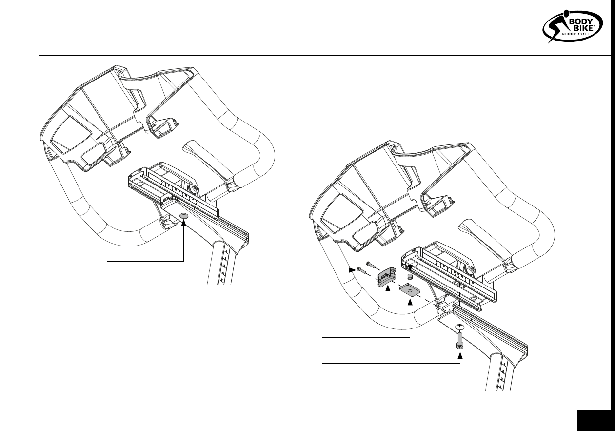
End cap
Brake plate
Bolt 8mm
Figure 12
Figure 13
Unscrew the
bolt
MAINTENANCE
below.
Mount the plastic tube on top of the bolt
from above.
10) Slide on the handlebar until
K is above
the line. Screw in the bolt.
11) Mount the end cap and the two 4mm bolts.
12) Tighten or loosen the 8 mm bolt to adjust the
smart handle. Make sure that everybody can release
the smart handle. If that is not the case, the smart
handle has been overtightened.
Plastic tube
4mm Bolt
017
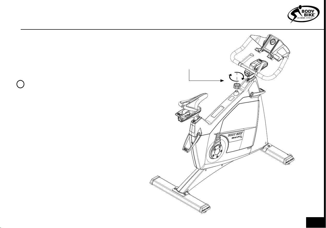
ADJUSTMENT HANDLE VERTICAL
Figure 15Figure 14
The vertical adjustment handles doesn’t need cleaning,
but with time they need to be tightened in order to
keep the posts in position. In order to do so a 6mm
Allen wrench is needed.
Front post adjustment
1) Open the service hatch as shown in figure 23.
2) Locate the adjustment bolt, just above the control
box. See figure 14.
3) Use a 6mm Allen wrench to tighten the front post.
4) Lock the adjustment handle and validate if the
front post is fixed. Continue until it is fixed in position.
Saddle post adjustment
1) Push the 6mm Allen wrench into the hole at the
back of the bike. Tighten carefully.
2) Lock the adjustment handle and validate if
the saddle post is fixed. Continue until it is fixed in
position.
Control
box
Adjustment
bolt
Adjustment
bolt
Saddle
post
Flywheel
018
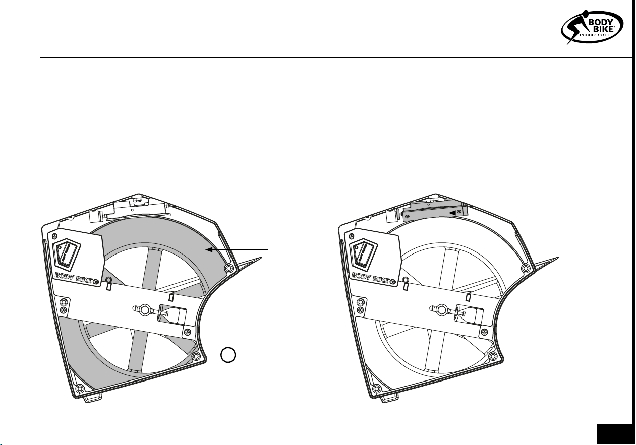
CLEANING THE FLYWHEEL
PLEASE NOTE
NEVER use alcohol or
chemicals when
cleaning the bike
!
Figure 16
CLEANING THE BRAKE BLOCK
MAINTENANCE
Figure 17
Flywheel
Kevlar
pad
To maintain a smooth ride it is important to clean the
flywheel from dust. No cleaning results in an uneven
watt output.
1) Remove the service hatch. See figure 23.
2) Vacuum clean the bike inside when necessary to
prevent dust from gathering on the flywheel. If dirt
has already gathered on the flywheel edge, use a
piece of rough felt to sand it down.
To maintain a smooth ride it is important to clean the
kevlar pad from dust. No cleaning results in a dark
slippery surface on the brake pad and uneven watt
output.
1) Remove the service hatch. See figure 23.
2) Use steel wool or something similar to remove the
slippery surface. Vacuum clean the kevlar pad and
the inside of the bike afterwards.
019
REMOVAL OF SIDE COVERS
The side covers can be removed e.g. if the
belt needs to be changed. This is technician
only.
1) Dismount the right pedal arm with an 8mm
Allen wrench. See figure 19.
2) Dismount the brake lever. See figure 20.
Hold the cap nut with a 17 mm wrench and
unscrew the brake handle.
Be sure to catch all internal parts in the brake
system.
3) Remove front and back post sealings. See
figure 18.
4) Remove the 4mm bolt in the front and
back of the bike. See figure 21.
PLEASE NOTE
Don’t change the poly v-belt if you
don’t have the right tools to install
it properly again.
!
Figure 19
Figure 18
Post sealing
Figure 20
Cap nut
Brake
handle
10mm
bolts
020
MAINTENANCE
Figure 22
Figure 21
5) Pull off the top cover. This makes the two hidden
bolts accessible. See figure 22
6) Remove the service hatch. See figure 23.
7) Unscrew all bolts on each side cover. 8 bolt on the
left side and 11 on the right side. Keep all the bolts to-
gether in order not to lose them.
4mm
bolt
4mm
bolts
8) It is possible to remove the side covers without re-
moving the 8mm bolt mounted in the bottom frame.
But we recommend that it gets removed. See figure
4.
PLEASE NOTE
When assembling, be sure that the steer and
saddle don’t get mixed up with others.
!
021
The Kevlar® pad on the BODY BIKE Synthetic Brake
has an expected durability of a minimum of 1500
hours, so eventually the brake pad will be worn. To
ensure that the brake pad is correctly mounted,
it has been pre-fitted to the block, and it is only
possible to purchase the complete brake block. Go
to page 30.
But most of the time, cleaning the Kevlar® pad is
enough to obtain a smooth ride again. See figure
17. If cleaning doesn’t help anymore follow the steps
below.
Inspect the Kevlar® brake pad after the first month
and thereafter every 3rd month. The Kevlar® brake
pad should be replaced before it is worn through
and reveal the black rubber.
To get to the brake block, it is necessary to remove
the service hatch. See figure 23.
1) Release tension completely on the brake. Coun-
terclockwise will loosen the resistance. See figure 8.
2) Remove the two screws holding the brake block
to the frame by using an 8 mm wrench, see figure
24.
REPLACING THE BRAKE BLOCK
SERVICE HATCH
Figure 23
Most maintenance and actions can be done through
the service hatch. Pull out the service hatch in the small
opening as shown in figure 23.
Small
opening
PLEASE NOTE
Be careful when remounting the
service hatch. The magnets make
the hatch snap and can squeeze
a finger.
!
022
MAINTENANCE
Remove
screws
Install and
twist
Reinstall the
last screw
Figure 26
Figure 25
Figure 24
3) Take the new brake block and fasten
it to the frame by tightening the screw
closest to the brake block. Then place
the block in the correct position under
the brake, see figure 25.
4) Fasten the remaining screw furthest
away from the block, and then make
sure that both screws are tightened
properly, see figure 26.
5) Grease should be applied to the
cavity on top of the brake block or to
the top nut on the brake to ensure a
smooth interaction between the two.
6) Finally, remount the service hatch.
Check with the BODY BIKE Indoor cycle
app that everything works as normal.
PLEASE NOTE
Clean the flywheels outer
diameter to an even smoother
ride.
!
023
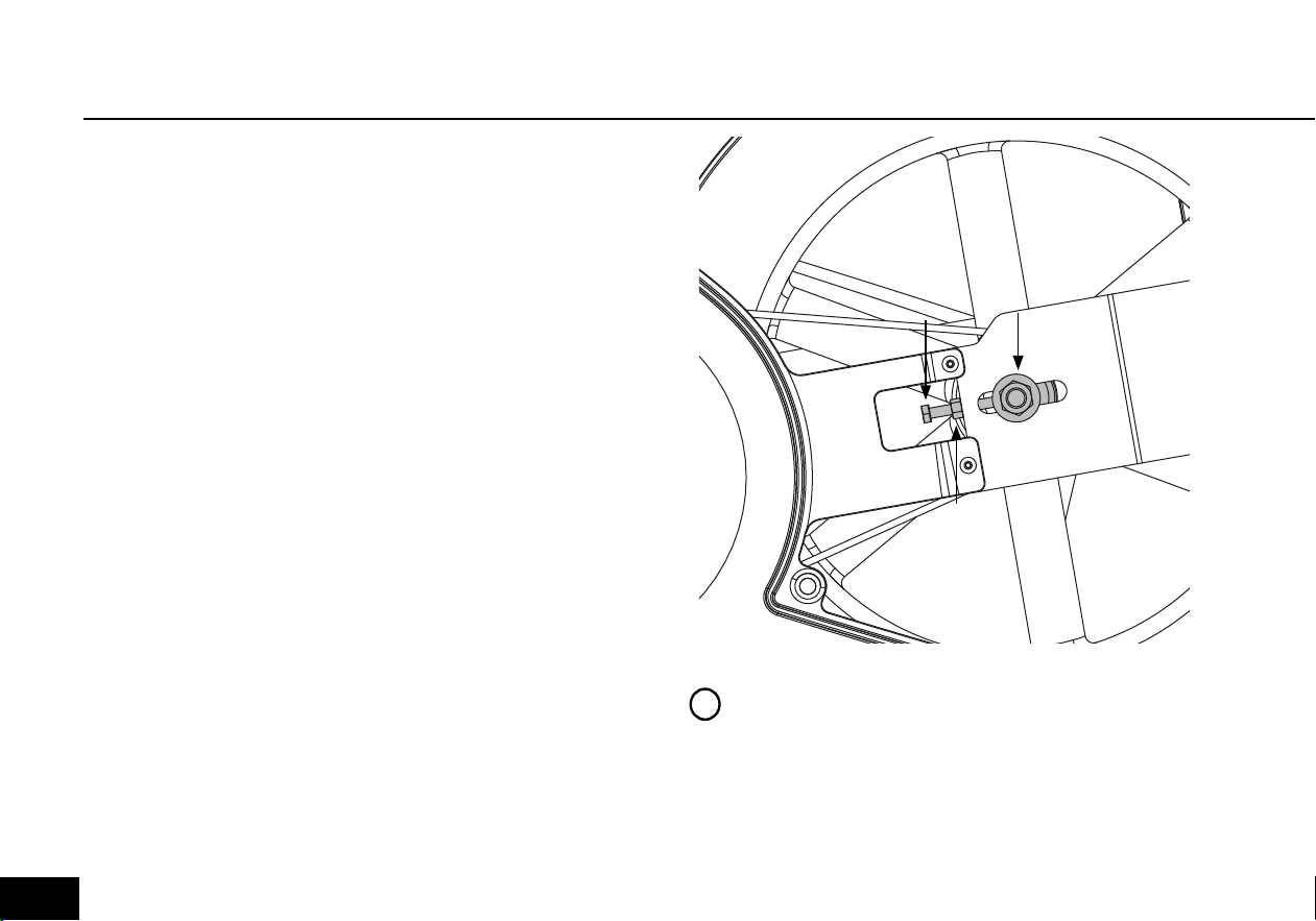
If the belt does not catch hold of the flywheel, it is time for
it to be tightened. Do not adjust this if you don’t have the
right tools. Check step 5.
1) Remove the service hatch on both sides of the cycle.
See figure 23.
2) Loosen the bolts (1) on both sides of the cycle with a 19
mm wrench, See figure 27
3) Loosen the nuts (2) on the counter bolt on both sides
of the cycle with a 10 mm wrench, see figure 27.
4) Use a wrench to tighten the counter bolts (3). On the
right side, the tool should be pulled downwards and on
the left side upwards to tighten with a 10 mm wrench.
5) The belt should be tightened to approximately 125
kg/229 Hz. To measure this, a special device can be
bought at your local BODY BIKE® distributor. Go to page
30.
6) Tighten the counter bolt (2) on both sides of the cycle
again.
7) And tighten the bolt(1) again on both sides of the cycle.
8) Close the cycle by fastening the two hatches again.
POLY-V BELT
PLEASE NOTE
The belt should be evenly tightened on both
sides.
The flywheel should be parallel with the long
main side member.
!
1
2
3
Figure 27
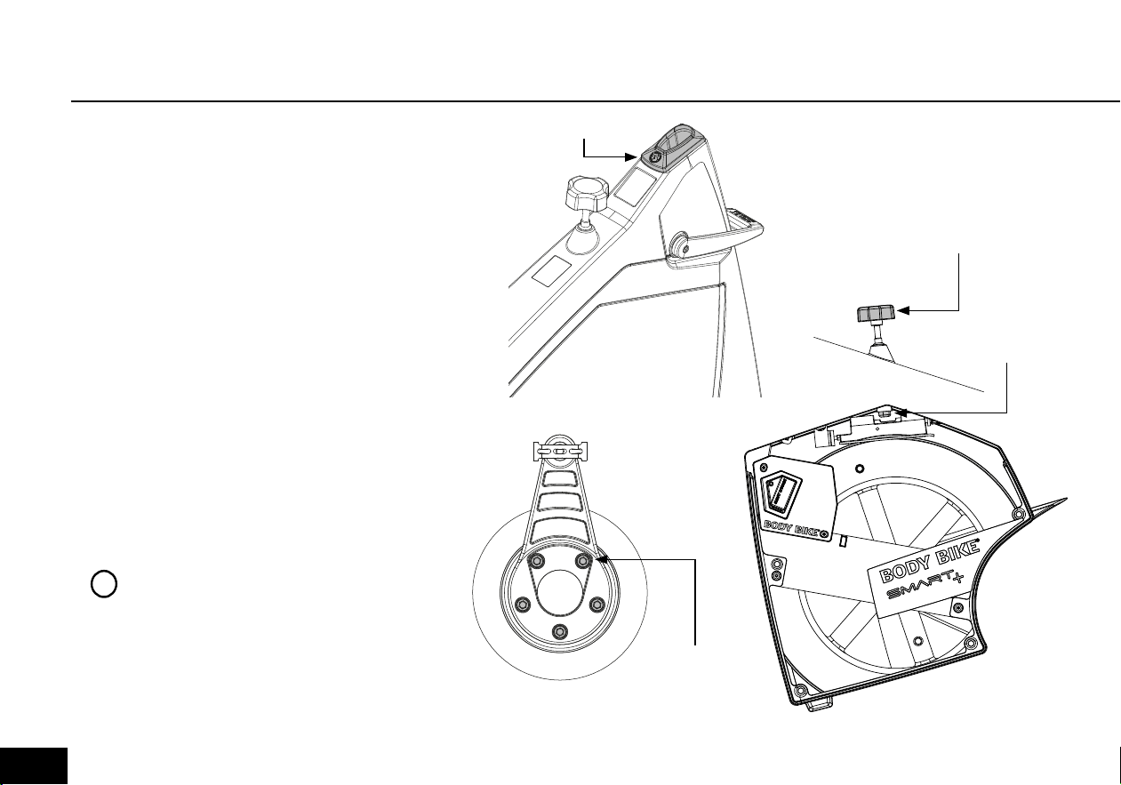
024
Every other week the posts need
cleaning to protect them from sweat
etc.
Pull out the seat- and front post until
a STOP sign appear then wipe them
clean with an oily cloth, see figure
28.
Do not pull the saddle and front post
out from the bike, unless it was the
intention. Remember each bike has
a bike nr. which is indicated on the
saddle and front post. Therefore, do
not switch posts between the bikes.
If this has happened, use the BODY
BIKE INDOOR CYCLE app to safely
switch the posts back. Step on the
pedals and the bike number will ap-
pear in the app. Match the number
with the number on the posts.
POSTS
PLEASE NOTE
The posts should be cleaned
every other week to keep them in
good condition
!
Created by Olena Panasovska
from the Noun Project
1x oily cloth
Release
Figure 28
Vertical
adjustment
Herizontal
adjustment
Pull until a
STOP sign
appear
MAINTENANCE
025
CONTROL BOX
The control box is located as shown in figure
40. This is the part of the bike which handles
all data. It communicates through ANT+ and
Bluetooth, which means that the SMART+ can
connect to a long range of different software.
Check out Explore and virtual software at
www.body-bike.com.
The LED light on the side of the control box tells
in which state the bike is in.
1) Constant blue. The bike is connected to a
device.
2) Flashing blue. The bike is searching for a de-
vice.
3) Purple. Bootloader menu. This is technician
only.
4) Yellow. Updating firmware. This is techni-
cian only.
5) Green. No loadcell number registred. This is
technician only.
Magnet
Control
box
LED
Light
Figure 29
PLEASE NOTE
The SMART+ can only be connected to
one device at a time trough bluetooth.
!
026
CONTROL BOX
If there is no light from the LED, then step on the pedals. The gener-
ator will then provide power to the control box. If there is still no light,
then open the service hatch and check if the generator spins, then
contact info@body-bike.com
Connect the BODY BIKE SMART+ with the BODY BIKE INDOOR CY-
CLE App and get a long range of different workout data.
1) Start time
2) Duration
3) Intensity scale in percentage.
4) Watt (Live, Avg and Max)
5) RPM (Live, Avg and Max)
6) Km/t (Live, Avg and Max)
7) Distance
8) Kcal/t (Live, Avg and Max)
9) HR (Live, Avg and Max)
10) FTP in percentage.
If some of the Live data doesn’t appear eg. RPM, then open the ser-
vice hatch and check if a magnet is mounted on the side of the fly-
wheel. If not then contact info@body-bike.com.
PLEASE NOTE
HR data is only possible if an HRM is connected with the BODY
BIKE app. Download the app on Play store or App store.
!
Figure 30
027

1) The bike is showing an uneven watt output?
In most situations, an uneven watt output is due to a
dirty flywheel and brake pad. This needs to be main-
tained in order to keep up a smooth ride. Go to page
19 and follow the instructions. If this doesn’t help go
to page 22-23 and follow the instructions.
TROUBLESHOOTER
4) Does the LED light, from the bikes left side,
have any meaning?
The BODY BIKE SMART+ is equipped with a control
box which is the heart of the bike. This box commu-
nicated through colour, telling which state it is in. Go
to page 26 and get an overview of the colour codes.
3) How to get rid of horizontal movement in the
saddle and steer?
If the front sled or saddle sled begins to slide forward
even though they are locked by the smart handles, it
is time to tighten them up Go to page 16-17 and fol-
low the instructions. Remember, do not overtighten.
Everybody needs to be able to adjust the bike.
6) Does the warranty cover me?
If something on your bike breaks it is always a good
idea to check if it is covered by the warranty. Go to
page 6 and 7. This gives you the overview that you
need. If the warranty covers the damage then go to
Page 30.
2) How to get rid of downwards movement in
the saddle and steer?
If the front post or saddle post begins to slide down
even though they are locked by the smart handles,
it is time to tighten them up. Go to page 18 and fol-
low the instructions. Remember, do not overtighten.
Everybody needs to be able to adjust the bike.
5) Does the BODY BIKE SMART+ provide LIVE
tracking data?
The BODY BIKE SMART+ provides a long list of track-
ing data. But an external device is needed in order to
display the data. Go to page 27 and download the
BODY BIKE INDOOR CYCLE app on your phone.
028

TROUBLESHOOTER
7) Can I replace the handlebar with a new one?
If there are several SMART+ bikes in the room, it is im-
portant not to switch the front- and saddle posts be-
tween the bikes. The bike has a unique number, which
is located on the posts. Go to page 25
10) Any good daily advice to keep the cycles in
a good condition?
It is not only important to follow the maintenance
but also very important to treat the bike well in every-
day use. This keeps the bikes in a good condition.
Go to page 4 and make sure that this is respected in
daily use.
9) What is the durability of the brake block?
It is expected that the durability of the brake block
is minimum 1500 hours. This can vary depending on
the power applied. Go to page 22-23 and check if it
is time to replace your brake block.
8) The poly-v belt doesn’t grip properly in the
flywheel?
This can easily be fixed. Go to page 24 and follow
the instructions. But do not perform this action if you
don’t have the necessary tools.
029

ONLINE INFORMATION
Need any spare parts?
If you need any spare parts for your bike, follow the link below and choose your location.
You will then get the direct contact information for your local distributor.
https://body-bike.com/distributors-search/
Need more information?
Wanna know more about your BODY BIKE SMART+, follow the link below.
https://body-bike.com/indoor-bikes/body-bike-smart-plus/
Need online support?
If you have any questions, problems or anything else regarding your BODY BIKE,
you are welcome to contact us on the mail below.
info@body-bike.com
Looking for another bike?
Take a look at our collection.
We provide a wide range of bikes and customization.
Follow the link below.
https://body-bike.com/category/indoor-bikes/
030

INDEX
Adjustment handles 16-18
Adjustment screw 17, 24
Assembly 8- 14
Belt 7, 24
Bottom frame 9-10
Bottle holder 11
Brake 22-23
Cleaning 19-25
Cover 20-21
Crank, warranty 6
Frame 6, 9-10
Grease 13, 16, 23
Handle 16-18
Handlebar 11
Height 4
Information, general 4
Length 4
Maintenance 15-27
Manufacturer 4
Mounting 9, 13, 22
Patent 4
Pedal 13-14
Poly V-belt 24
Post (front and seat) 25
Product description 4
Rubber feet 4, 7, 9
Saddle 12
Side cover 20-21
Tools 13, 20
Trouble shooter 28-29
User weight 4
Wear and tear 7
Weight 4
Width 4
Wheel 19
031

BODY BIKE
®
International A/S
Niels Bohrs Vej 2
DK-9900 Frederikshavn
Denmark
Phone: +45 9843 9696
www.body-bike.com
Edition 5.0