Models covered by this instructions:
SIU3, SIU5, SU404, SU405, SU401, SIU14, SIU24, SIU8
*** BEFORE INSTALLATION ***
ENSURE THERE IS NO VISIBLE OR HIDDEN DAMAGE
SUSTAINED DURING SHIPPING
*** SHIPPING DAMAGE ***
MUST BE REPORTED WITHIN 5 DAYS OF RECEIPT
INSTALLATION
INSTRUCTIONS
CARE AND USE MANUAL FOR:
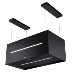
ISLAND RANGE HOODS

WARNING
Thank you for purchasing a Sirius Range Hood.
Please read all the instructions in this manual before
installing the appliance.
Save these instructions for future reference.
Only use this appliance as an exhaust ventilation system for the removal of coo-
king vapors. DO NOT use to expel ammable substances or any other materials
or vapors.
The installation procedures in this manual are intended for qualied installers, ser-
vice technicians or persons with similar qualied background.
DO NOT attempt to install this appliance yourself.
Ensure that electrical power is turned off at source before commencing installation.
All electrical wiring must be properly installed, insulated and grounded and conform
to all applicable codes and standards.
Make sure all existing duct work is clean of grease build up, or duct work should be
replaced, if necessary, to avoid the possibility of a grease re. Check all joints on
ductwork to ensure proper connection and all joints should be properly taped. Be
careful when cutting through ceilings or walls not to damage any hidden pipes or
electrical wiring. Ensure your kitchen has sufcient air return vents to replace the
exhausted air.
Fan ducts should always be vented to the outside of your home and never into
spaces within walls, ceilings, lofts or attics. Only use rigid, smooth steel for ducting.
The exhaust point of the blower requires a 6” round or 8” connection.
2
TABLE OF CONTENTS
BEFORE YOU BEGIN 4
MINIMUM AND MAXIMUMS 4
DUCTING 4
Duct Run Calculation 5
ELECTRICAL 5
Electrical Supply 5
INSTALLATION 6
Structural preparation for the hood fan installation 6
Fixing the Main Support Bracket 6
Attaching the range hood to the ceiling 7
Connecting Electricity and Ducting 8
Re-Circulating Requirements 8
Schematic of modular island components 9
OPERATING PROCEDURES 11
General Advice 11
Functions 11
MAINTENANCE 14
Cleaning the Filter 14
Cleaning the Hood 14
Substitution of the LED bar 15
WARRANTY 16
3

BEFORE YOU BEGIN: It is advisable to
test run the range hood before installa-
tion.
BEFORE STARTING – please read this
entire document and ensure you are fully
conversant with the require-ments and li-
mitations. These units weigh approximately
125lbs and therefore require a minimum of
two people to install.
BEFORE YOU BEGIN
The manufacturer declines all responsibility
in the event of failure to observe the instruc-
tions given here for installation, maintenan-
ce and suitable operation of the product. The
manufacturer further declines all responsibi-
lity for injury due to negligence and the war-
ranty of the unit automatically expires due
to improper maintenance and/or installation.
Use the shortest most direct ductwork rou-
te possible. Only use metal ducting - plastic
ducting is generally not permitted by code.
Do not use exible metal ducting as the rid-
ges of the ducting cause severe air turbulen-
ce and will signicantly reduce the efcien-
cy of any hood -THIS TYPE OF DUCTING
WILL REDUCE EFFICIENCY BY 50%.
Vent hoods may interrupt the proper ow of
exhaust gases from re-places, gas furna-
ces and gas water heaters. To minimize the
risk of drawing these lethal gases back into
the home please follow the heating equip-
ment manufacturers safety standards and
guidelines. Refer to NFPA and ASHRAE for
additional information.
DUCTING
If vented externally, 6” / 150mm round duc-
ting must be available for the hood through
the ceiling, in line with the central vertical
axis of the range hood.
If i’s gas range or cook top recommanded
8”.
This unit must have it’s own ductwork. Do
not under any circumstances vent this unit
into any other ductwork or exhaust ducting
in the building.
PLEASE NOTE THAT THE DUCT OUT-
LET ON THE TOP OF THE POWER UNIT
IS OFF SET FROM CENTRE AND THE-
REFORE AN ADJUSTABLE 6” ROUND
BEND WILL BE REQUIRED TO LINE THE
EXHAUST OUTLET WITH THE 6” HOLE IN
THE CEILING MOUNT BRACKET.
MINIMUM AND MAXIMUMS
Min length of power unit structure with de-
ector connected = 36.6”
Min length of power unit without deector = 32”.
Max length of power unit structure = 48”.
Recommended height from cook top to un-
derside of hood = 30” for gas, 25” for electric.
4
Maximum Run
6” or 3 1/4 x 10” duct * 100 FT
Deduct
Each 90 elbow used 15FT
Each 45 elbow used 9FT
Each 6” or 3 1/4 x 10” duct
Transition used 1FT
Each 3” 1/4 x 10” to 6”
Transition used 5FT
Side Wall with damper 30FT
Roof Cap 30FT
Duct Run Calculation.
The maximum duct run before effecting the
performance of the hood is 100’. Calculate
your duct run by measuring linear feet and
adding the elbows, transitions and caps ba-
sed on the table below.
* Gas range or gas cook top recommanded
8”.
Electrical Supply.
This appliance requires 120V/60Hz, 3amp
electrical supply - ensure an appropriately
qualied person completes the electrical ho-
ok-up. The connection point for the electrical
supply is at the top of the unit, therefore the
electrical supply must be run down from the
ceiling alongside the ductwork.
All electrical and venting hook-ups must be in
place before commencing installation of the
hood-fan.
ELECTRICAL
WARNING: All electrical work must be
performed by a qualied electrician.
Please ensure that the appropriate electrical
codes or prevailing local building codes and
ordinances are adhered to.
Ensure that the electricity supply is discon-
nected at source. Do not use an extension
cord or adapter plug with this appliance.
This appliance must be grounded. Connect
to a properly grounded branch circuit, pro-
tected by a 15 amp circuit breaker.
5
Structural Preparation for the Hood Fan
Installation.
The island hood weighs approximately 125
lbs. It is therefore imperative that a substan-
tial structure is prepared in the ceiling to at-
tach the range hood to. Ideally block off an
area of at least 12”x12” between the ceiling
joists using 2x4’s. Allow for a hole through
the center of this blocking of at least 6” in
diameter through which to pass the duct-
work and electrical cable.
The underside of the hood must not be clo-
ser than 30” from the cook-top and ideally
not higher than 32”above the cook-top. It is
strongly recommended, at this point, that
calculations and measurements be made
and all planning and heights be nalized.
You will need to t the appropriate length of
ducting to the hood fan before installing it to
the ceiling.
Planning should consist of a test assembly
of the power unit and telescoping structure
before attempting to mount everything to the
ceiling. By following this test assembly you
will be able to nalize the correct length of
the assembly before mounting it to the cei-
ling.
Test assembly should include actually at-
taching the following items together – refer
schematic of components and “Fixing the
main support brackets” below – Brackets
A, B, C, power unit and deector if re-circu-
lating.
This is also a good time to test the electrical
functioning of the hood before it is installed.
Before switching on the light or lights, ensu-
re the tape holding the globes in place has
been removed.
The globes gets extremely hot and will very
quickly burn the tape and discolor the glo-
bes irreparably.
INSTALLATION
Do not switch on the lights with the hood at
on any surface as the in-tense heat will burn
the surface and destroy the lamps. Connect
a power supply to the unit and test all fun-
ctions.
Installation of the island hood consists of -
xing the ceiling Bracket A substantial mem-
bers in the ceiling. The bracket must be xed
to the frame by screwing through the ceiling
into the heavy members inside the ceiling.
This is critically important as the entire
hood fan hangs from this position, and
ceiling board alone will not support the
weight of the hood fan. Discard the plastic
wall plugs supplied for xing the bracket to
the ceiling - these are not appropriate for
North American structures.
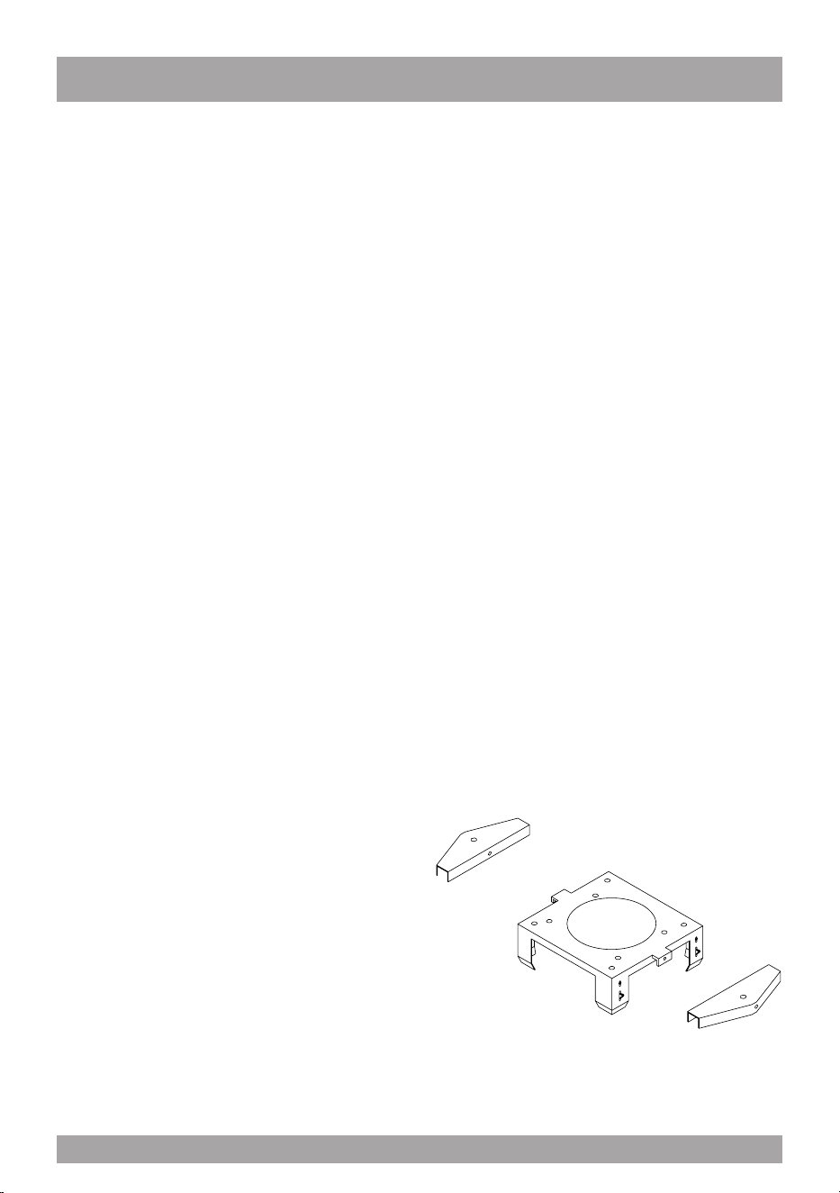
Fixing the Main Support Brackets
Using Bracket “A” as a template mark the cei-
ling where the xing screws “A” will be posi-
tioned - remember the correct orientation
from above. Attach bracket “A” to the ceiling
permanently. If re-circulating, attach the de-
ector to Bracket “A” before xing it to the
ceiling – refer schematic on page 5.
The 2 brackets for the support of the chimney
(Part A) is to be installed to Bracket A with
the screws (C Fig.1) Fix the structure on the
ceiling by inserting the 2 dowels.
g. 1
6

Fix Bracket “C” to the power unit with the
nuts and washers supplied (Items “A” on the
schematic on page 5). Please ensure that
the bracket is installed as shown to enable
full ac-cess to the square plastic black box
and the metal electrical junction box. Slide
Bracket “B” over Bracket “C” (once again
ensure full access to the plastic and electri-
cal boxes is main-tained) and x it in place,
at the previously calculated length using the
machine screws denoted by items “B” on the
schematic on page 5.
Check that the plastic aps at the exhaust
outlet for the fan move freely and have not
become jammed during shipping or whilst
working with the power unit. Connect an ap-
propriate length of ducting to the unit.
Do not x the ducting to the outlet with
screws - use DUCT TAPE.
Only for SU 401,SIU3, SIU5, SIU14, SIU24:
Install the glass as per the instructions con-
tained in the packaging of the glass. (only
for SU401).
Stand the assembled structure on a clean
soft surface. Ensure the underside of the
hood does not get scratched and slide the
chimneys of the assembled structure from
the top down as per the schematic on page
5. Ensure that the holes for xing the deco-
rative chimney are correctly orientated with
the holes at the top of bracket A.
Attaching the Range Hood to the Ceiling.
The entire structure that has been pre-as-
sembled above, must now be hoisted up to
the ceiling. A few things have to happen at
once here: the slots (as discussed below)
need to be engaged and the ductwork must
make connection with the length of ductwork
on the structure.
This will require two strong people –do not
attempt this step on your own. Bracket “B”
has slots, position C per Diagram “A” (refer
to page 5), at the top that will receive the
spring clips located on Bracket “A” -THIS IS
A TEMPORARY HOLD ONLY –DO NOT
RELY SOLELY ON THESE CLIPS TO
HOLD THE HOOD UP – THEY WON’T.
Once “hooked” by the spring clips immedia-
tely secure the structure with the machine
screws at point “E” on the schematic on
page 5 – this must be done immediate-
ly and should not be skipped. Raise the
upper chimney to the ceiling and x it to the
bracket “A” with the screws supplied “D”.
Ensure the entire structure is sturdy - serious
injury, death and MAJOR damage could re-
sult should the unit not be well connected to
the frame structure within the ceiling.
This is of utmost importance - do not go any
further until this has been tested and double
checked - the installer has sole responsibi-
lity for the safe installation of this product.
Only for SU 404-405: Stand the assem-
bled structure on a clean soft surface. En-
sure the underside of the hood does not get
scratched and slide the chimneys of the as-
sembled structure from the top down as per
the schematic on page 5. Ensure that the
holes for xing the decorative chimney are
correctly orientated with the holes at the top
of bracket A.
7
This will require two strong people –do not
attempt this step on your own. Bracket “B”
has slots, position C per Diagram “A” (refer
to page 5), at the top that will receive the
spring clips located on Bracket “A” - THIS
IS A TEMPORARY HOLD ONLY - DO
NOT RELY SOLELY ON THESE CLIPS
TO HOLD THE HOOD UP - THEY WON’T.
Once “hooked” by the spring clips immedia-
tely secure the structure with the machine
screws at point “E” on the schematic on
page 5 - this must be done immediately
and should not be skipped.
Ensure the entire structure is sturdy- serious
injury, death and MAJOR damage could re-
sult should the unit not be well connected to
the frame structure within the ceiling.
This is of utmost importance – do not go any
further until this has been tested and double
checked – the installer has sole responsibi-
lity for the safe installation of this product.
Once the entire structure has been xed to
the ceiling slide the chimneys on the assem-
bled structure from the bottom up as per the
schematic on page 5. And x the chimneys
with the screws supplied. Raise the upper
chimney to the ceiling and x it to the bra-
cket “A” with the screws supplied “D”.
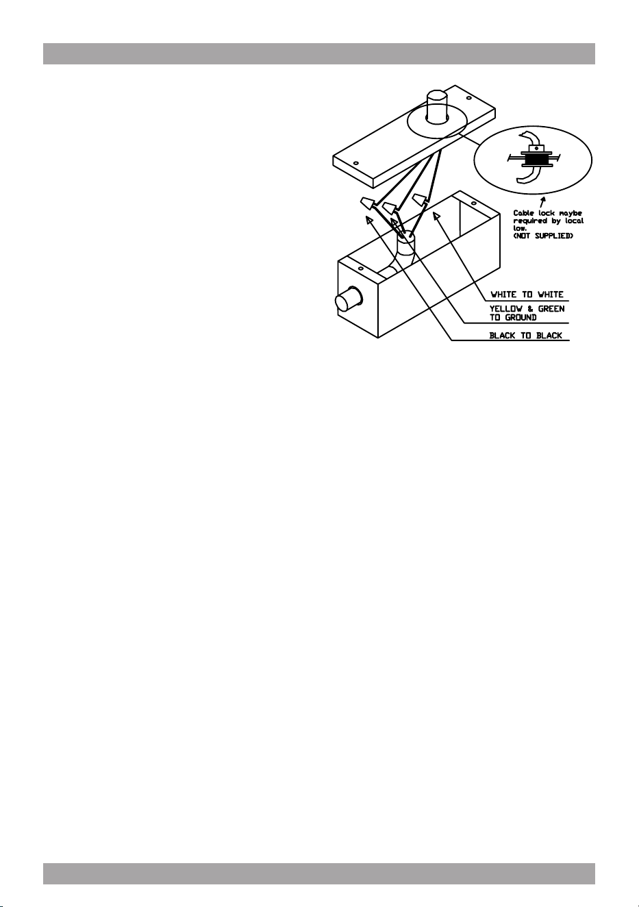
Connecting Electricity and Ducting.
Make sure power is turned off at the source.
Make the electrical connection (see gure
2). Test the functioning of the hood. Slide the
upper chimney into place and attach with
the machine screws provided to Bracket “A”.
Re-Circulating Requirements.
Fit the carbon lter after the installation is
complete – these t in behind the aluminum
grease lter.
A short length of ductwork must be connec-
ted from the exhaust outlet up to the deector
(must be purchased with hood).
The deector, after attaching part B with
screws E connects to the top of Bracket “A”
and forces the air out through the grills on
the side of the chimney section back into the
room. (see diagram C).
g. 2
8
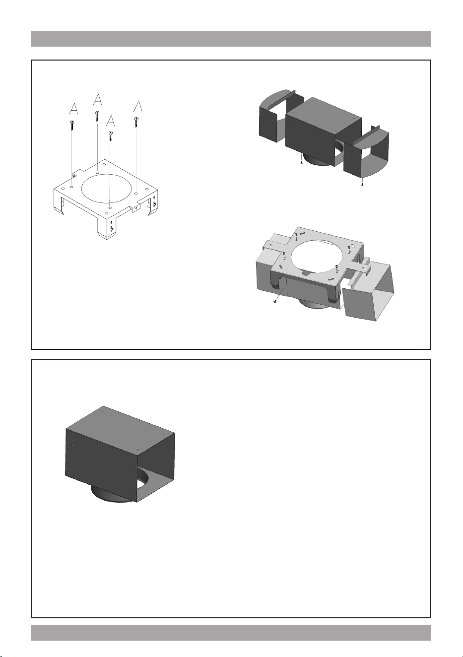
Diagram c - Deector
Bracket
Deector FOR SU404
E
E
Part B
Deector FOR SU405
E
E
Part B
Part B
Deector FOR SIU3, SIU5
Deector attaches to ceiling mount bracket when island hood is installed in re-circu-
lating mode and the air that has passed through the fat and carbon lters is returned
to the room via a short length of 6” round ductwork attached to the power unit and
deector.
9
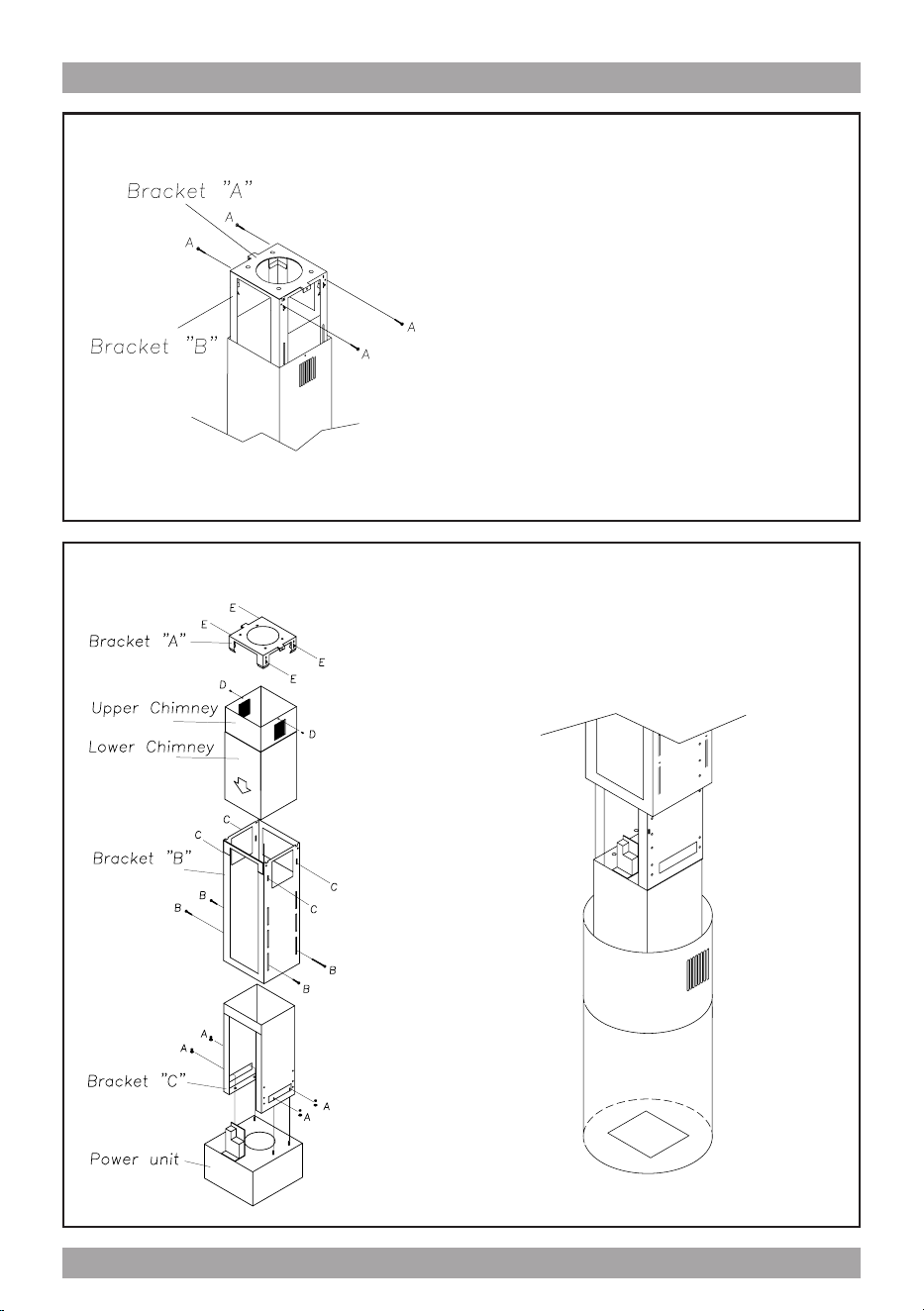
Diagram b – Securing Bracket “A” to “B”
Please note – this is critically important - do not rely on the spring clips.
Diagram A – Main Assembly
FOR SU404
10
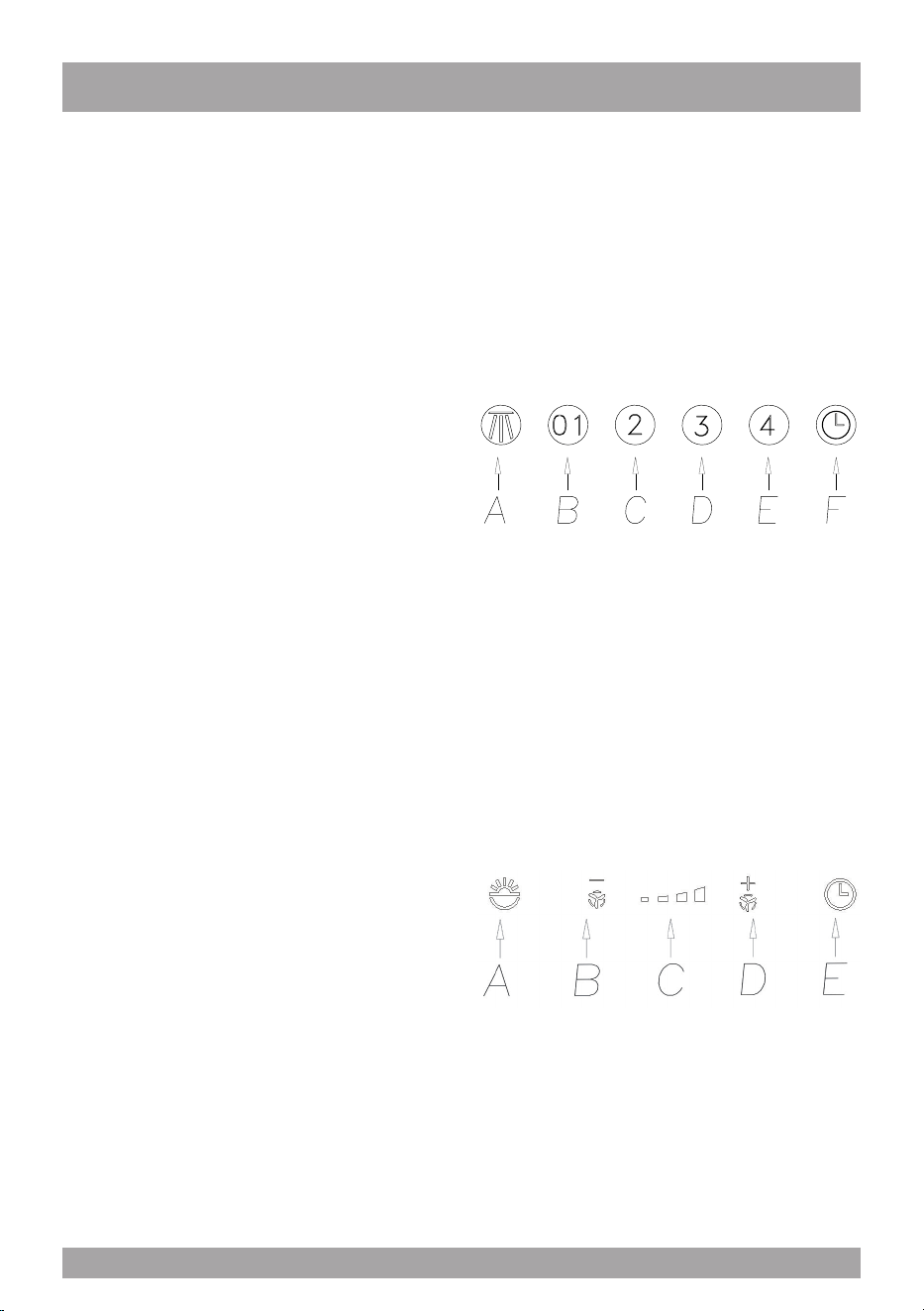
FUNCTION
SIU3 – SIU5 (Fig.3)
A: Light ON/OFF button
B: Blower Speed 1 (low) or OFF
C: Blower Speed 2 (medium)
D: Blower Speed 3 (high)
E: Blower Speed 4 (intensive)
F: 10 Minute Timer
OPERATING PROCEDURES
Read all the instructions before operating
the appliance. Save these instructions for
future reference.
General Advice.
Ensure that the grease lters are in place.
Without these components, operating blo-
wers could catch on to hair, ngers and lo-
ose clothing.
Keep fan, lters and surfaces clean of gre-
ase and fat. Always turn hood fan ON when
cooking. NEVER leave cooking unattended.
NEVER dispose cigarette ashes, ignitable
substances or any foreign objects into blo-
wers.
Cooking that generates ame is not recom-
mended as this hood is equipped with a
thermal overload that will shut down the mo-
tor if it senses excessive heat. When frying,
oil in the pan can easily overheat and ignite.
Heat oil slowly in an appropriately sized pot
(covering the entire burner) to reduce the
risk of boiling over and burning.
In the event of a range top grease re, ob-
serve the following:
Switch OFF the range hood. Turn off the
cook top then smother ames with a close
tting lid, cookie sheet or other metal tray. If
the ames do not go out immediately.
EVACUATE AND CALL THE FIRE DE-
PARTMENT.
Never pick up a aming pan – you may be
burned. DO NOT USE WATER including
wet dishcloths or towels, as a violent steam
explosion may occur.
g. 3
TC models (SIU24) g. 4
A: Light switch On/Off
B: Reduce speed
C: Luminous telltale
D: Incrase speed
E: 10 - minute timer
The touch control key allows the function de-
sired by touching the relative key.
g. 4
11
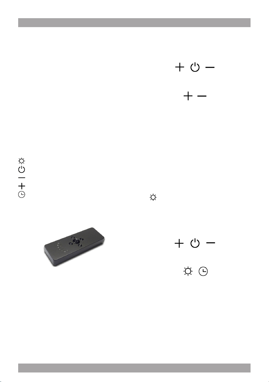
SU401 - SU404 – SU405
RC001
RADIO CONTROL
Radio control used for the remote operation of
ducted cooker hoods.
TECHNICAL DATA
- Alkaline battery powered: 12 V mod. 27A
- Operating frequency: 433.92 Mhz
- Combinations: 32.768
- Max. consumption: 25 mA
- Operating temperature: -20 ÷ + 55 °C
- Dimensions: 130 x 45 x 15 mm.
OPERATING DESCRIPTION
The transmitter is equipped with 5 buttons for coo-
ker hood management, as specied below:
: Light ON/OFF command.
: Motor ON (speed level 1) / OFF command.
: Reduce speed.
: Increase speed.
: 10-minute timer.
INITIAL OPERATING CONDITION
The manufacturer supplies the radio control unit
ready to be used with codes preset in the Factory
OPERATION MODE
Standard conguration:
Standard conguration requires all “cooker hoods
- radio control - system” to be provided with the
same transmission code. In the event two cooker
hoods - radio control system are installed in the
same room or nearby, each system may affect the
operation of the another. Therefore, the code of
one radio control system must be changed.
Generating a new transmission code:
The radio control system is provided with preset
codes. Should new codes be required, proceed
as follows: Press simultaneously buttons:
for two seconds. When Leds light on, press but-
tons:
(within 5 seconds). Leds ashing 3 times indicate
the procedure is completed.
WARNING! This operation deletes permanen-
tly the preset codes.
Learning the new transmission code:
Once the transmission code is changed in the ra-
dio control unit, the electronic central unit of the
cooker hood must be made to set the new code in
the fol- lowing way:
Press the main power-off button of the hood and
then restore power to the electronic control unit.
Within the next 15 seconds, press the Liight But-
ton to synchronise the central unit with the
code.
Reset of the Factory conguration:
To restore the Factory conguration, follow the
procedure described below: press simultaneously
buttons:
for 2 seconds. When Leds light on, press buttons:
(within 5 seconds). Leds ashing 6 times indicate
the procedure is completed.
WARNING! This operation deletes permanen-
tly the preset codes.
Emergency button:
In the event that the radio control does not work,
use the emergency button to switch the appliance
off. After any necessary repairs have been perfor-
med, reset the emergency button.
12
WARNING
The battery should be replaced every year to
guarantee the optimal range of the transmitter.
To replace the exhausted battery, take the pla-
stic lid off, remove the battery and replace it
with a new one, observing the correct battery
polarities.
Used batteries should be discarded in special
collection bins.
The below product:
RC001 Radiio Controll
complies with the specications set out in the
R&TTE Directive 99/5/EC.
WARNING
Any adjustments or modications which have
not been expressly approved by the holder of
the legal conformity certicate may invalidate
the user’s rights relating to the operation of
the device.
The products are endowed with an electronic de-
vice which allows the automatic switching off after
4 hours working from the last operation.
13

Warning The battery should be replaced
every year to guarantee the optimal range
of the transmitter. To replace the exhau-
sted battery, take the plastic lid off, remo-
ve the battery and replace it with a new
one, observing the correct battery polari-
ties. Used batteries should be discarded
in special collection bins.
Cleaning the Hood.
Cleaning of the internal parts should be done
with a clean damp (not excessively wet) cloth
together with regular household detergent.
The external stainless steel elements should
be cleaned with a good quality foaming stain-
less steel cleaner. Read the manufacturers
directions. Generally they recommend that
the foam be sprayed onto a clean dry cloth
and then applied to the stainless steel. Allow
the foam to react on the surface for a few mi-
nutes and then wipe with a clean dry cloth.
On the surfaces that are exposed directly
to heat from the cook-top, it is advisable to
clean these on a regular basis to avoid the
marks from becoming baked on.
Do not under any circumstances use an
abrasive type cleaner as this will scratch and
damage the stainless steel nish. Glass com-
ponents should be cleaned with a product
such as Windex.
MAINTENANCE
The hood-fan should provide many years of
trouble free service provided it is maintained
properly.
Cleaning the Filter.
Clean the grease lter either by carefully
hand washing, (so as not to damage the
lter design) or, preferably in a dishwasher.
Depending on use, the lters should be cle-
aned at least every two weeks in a dishwa-
sher.
If a carbon lter has been tted this must be
replaced at least every 6 months as a mini-
mum. Depending on cooking style and na-
ture of cooking (greasy foods, fry’s, curries
etc) would probably require more frequent
replacement – if odors start to manifest
themselves when cooking it is time to repla-
ce the carbon lter . We suggest you retain
a spare set. These can be ordered from the
supplier of your range hood.
Filter requires washing indicator: after 30
hours of use, all the buttons will light up to
remind you that the grease lter should be
cleaned. Follow the instructions for cleaning
lters in this booklet. Once the grease lters
have been cleaned and replaced, reset by
pressing the timer button (F). Do not rely so-
lely on this indicator. Generally, the grease
lter should be washed on a regular basis to
avoid grease lter res.
The blower should be turned on for appro-
ximately 5 minutes before cooking in order
to establish air currents upward through the
hood. Use the low speeds for normal use
and the higher speeds for strong odors and
fumes.
14
Light Bulb Replacement.
(if in doubt, call 877-474-8770)
FOR SU401 – SU404 – SU405
Turn blower and lights off. Make sure the
lights are cool.
If new lights do not operate, check fuses and
be sure globes and breakers are inserted
correctly.
Do not remove the entire xture (socket) as
this is very difcult to reinstall. Gently pry the
bulb from the xture using a soft instrument
such as a toothpick. Steel instruments will
scratch the surface (refer to gure 5).
Replace the appropriate bulb. Check parts
brochure or specication sheets on our web-
site. Wipe both sides of the glass whilst it is
out. Re-insert the glass-blocking ring and fa-
sten it.
If it is not possible to access the back side of
the lamp, you have to: provide yourself with
a sharp utensil, insert the utensil between the
lamp and the stainless steel frame (on the
side where the little support wings are pla
ced), push to remove the lamp from the coo
ker hood.
g. 5
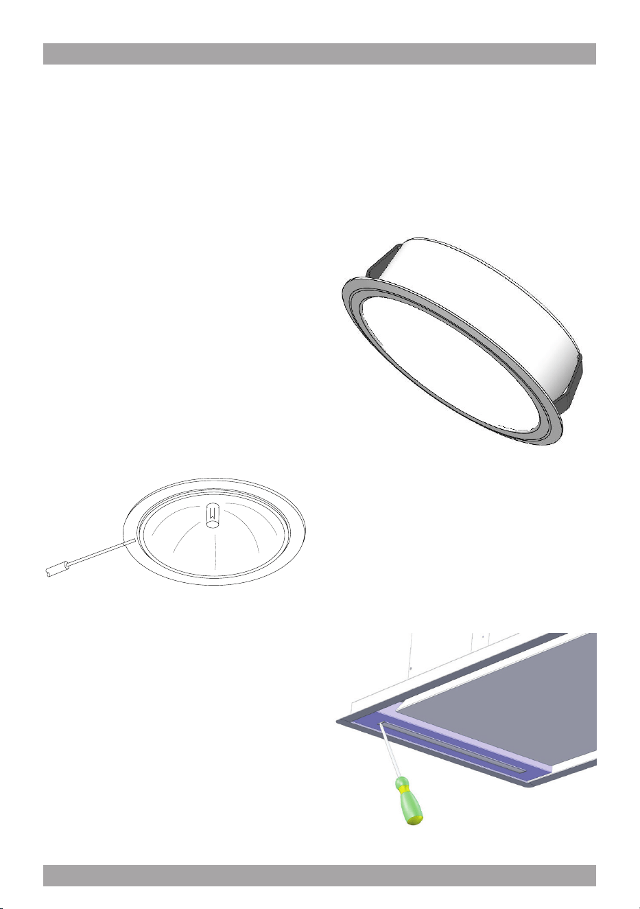
FOR SIU3 – SIU5 – SIU14
To replace the round LED lamps (g. 6)
you have to check rst if it is possible to
access the back side of the lamp with your
hand.
If it is possible to access the back side of the
lamp, you have to: insert your hand , push at
the same time both support wings of the
lamp, push to remove the lamp.
FOR SIU24
Substitution of the LED bar:
Using an appropriate tool, remove the LED
bar from its seat (refer to Fig. 7), disconnect
it electronically using the appropriate con-
nector then substitute it with a LED bar with
same characteristics.
g. 7
g. 6
15

Three Year Limited Warranty
YOU MUST REGISTER THE PURCHASE OF YOUR PRODUCT ON LINE AT
www.siriuscappe.com/usa/warranty.htm TO CONVALIDATE YOUR WARRANTY.
YOU CAN FIND THE DATA OF YOUR HOODS ON A LABEL INSIDE THE HOOD. JUST REMOVE
THE GREASE FILTER TO READ IT.
Sirius S.P.A.
Zona industriale Berbentina 6/A
60041 SASSOFERRATO (AN)
ITALY
Sirius after sale service
Telephone (toll free): 1-877-474-8770
Email: Sirius@adcoservice.com
Register Online! www.siriuscappe.com/usa/warranty.htm
90010004020 - 05/19
WARRANTY SERVICE
To qualify for warranty service, you must notify Sirius After sale service at the email address
stated below or call toll free USA 1-877-474-8770 and provide the model number, description
of the fault or defect and original date of purchase. Sirius reserves the right to request proof
of original purchase. Sirius will at its sole option and discretion replace products that arrive
damaged through shipping, provided shipping damage is reported as stated above WITHIN 5
BUSINESS DAYS OF RECEIPT of the shipped product or products.
ONE YEAR SERVICE REPAIR WARRANTY:
During the rst year from date of original purchase, Sirius will, at its option, repair or replace, without
charge, any product or part which is found to be defective under normal use and service.
THREE YEAR PARTS WARRANTY:
For three years from date of purchase, Sirius will provide free of charge, non-consumable replacement
parts which are found to be defective under normal use and service.
WHO IS COVERED:
Sirius warrants to the original consumer purchaser of its products that such products will be free from
defects in materials and workmanship for a period of three years from the original date of purchase.
There are no other warranties, express or implied, including, but not limited to, implied warranties of
merchantability or tness for a particular purpose or application.
WHAT IS NOT COVERED:
This warranty does not extend to lters, lamps, batteries, ducts and ductwork components. This war-
ranty does not cover normal maintenance and service or products or parts which have been subject to
misuse, negligence, accident, improper maintenance or repair, faulty installation or installation contrary
to recommended installation instructions. The warranty on glass screens is limited to manufacturing
defects only and expressly excludes cracks and breakages as a result of faulty installation.
Labor and
associated costs associated directly with removal and re-installation are expressly excluded.
The duration of any implied warranty is limited to the three year period as specied for the express
warranty. Some states and provinces do not allow limitation on how long an implied warranty lasts, so
the above limitation may not apply to you.