GT12M-THF/GT15M-THF TRANSDUCER
INSTALLATION INSTRUCTIONS
Important Safety Information
WARNING
See the Important Safety and Product Information guide in the chartplotter, fishfinder, or sonar module product
box for product warnings and other important information.
You are responsible for the safe and prudent operation of your vessel. Sonar is a tool that enhances your
awareness of the water beneath your boat. It does not relieve you of the responsibility of observing the water
around your boat as you navigate.
CAUTION
For the best possible performance and to avoid potential injury, damage to the device, or damage to your vessel,
installation by a qualified marine installer is recommended.
Failure to install and maintain this equipment in accordance with these instructions could result in damage or
injury.
To avoid possible personal injury, always wear safety goggles, ear protection, and a dust mask when drilling,
cutting, or sanding.
NOTICE
When drilling or cutting, always check what is on the opposite side of the surface to avoid damaging the vessel.
Read all installation instructions before proceeding with the installation. If you experience difficulty during the
installation, contact Garmin
®
Product Support.
To prevent interference and avoid possible overheating damage, do not install the transducer near the engine or
in the engine room.
To prevent damage to the cable and the transducer, do not use the cable to pick up or pull the transducer.
Always operate the transducer when it is submerged. Operating the transducer when it is exposed to the air may
result in damage due to overheating.
To prevent permanent damage to the surface of the transducer, do not use solvents such as mineral spirits,
acetone, Methyl Ethyl Ketone (MEK), or similar products when cleaning. Do not use a power sander or pressure
washer to clean the transducer.
GUID-FBCD49EF-8D56-47CE-97B4-1B8840440007
v2
August 2024

Important Hull Material Considerations
Not all transducer models can be installed in all hull types. When installing this transducer, it is critical that you
install the type of transducer that is designed for use with the material of the boat hull.
The GT15M-THF transducer is made from stainless steel, and can be installed in a fiberglass, wood, composite,
aluminum, or steel-hulled vessel. When installing this model in an aluminum or steel hull, you must install the
included galvanic isolation components as instructed.
NOTICE
Installing the GT15M-THF transducer in an aluminum or steel hull without the galvanic isolation components
will create galvanic corrosion that may result in water entry around the transducer.
The GT12M-THF transducer is made from brass, and can be installed in a fiberglass, wood, or composite-hulled
vessel. You must not install this model in an aluminum or steel hull.
NOTICE
Installing the GT12M-THF transducer in an aluminum or steel hull will create galvanic corrosion that may result
in water entry around the transducer.
Software Update
You must update the Garmin chartplotter software when you install this device. For instructions on updating the
software, see your chartplotter owner's manual at support.garmin.com.
Tools Needed
• Drill
• 3mm (
1
/
8
in.) drill bit
• Adjustable wrench suitable for nuts up to 75 mm
• Marine sealant (flexible, fast-cure type, for below the waterline)
• Mild household detergent or rubbing alcohol
• Sandpaper
• Masking tape
• Waterproof electrical tape
• Grommets (optional)
• Water-based anti-fouling paint (optional)
These additional items are needed depending on the installation.
For mounting in a fiberglass hull:
• 73 mm (2
7
/
8
in.) hole saw
• Marine grade epoxy resin for fiberglass (cored fiberglass hulls)
For mounting in a metal hull:
• File
• 75 mm (3in.) hole saw
2
Mounting Location Considerations
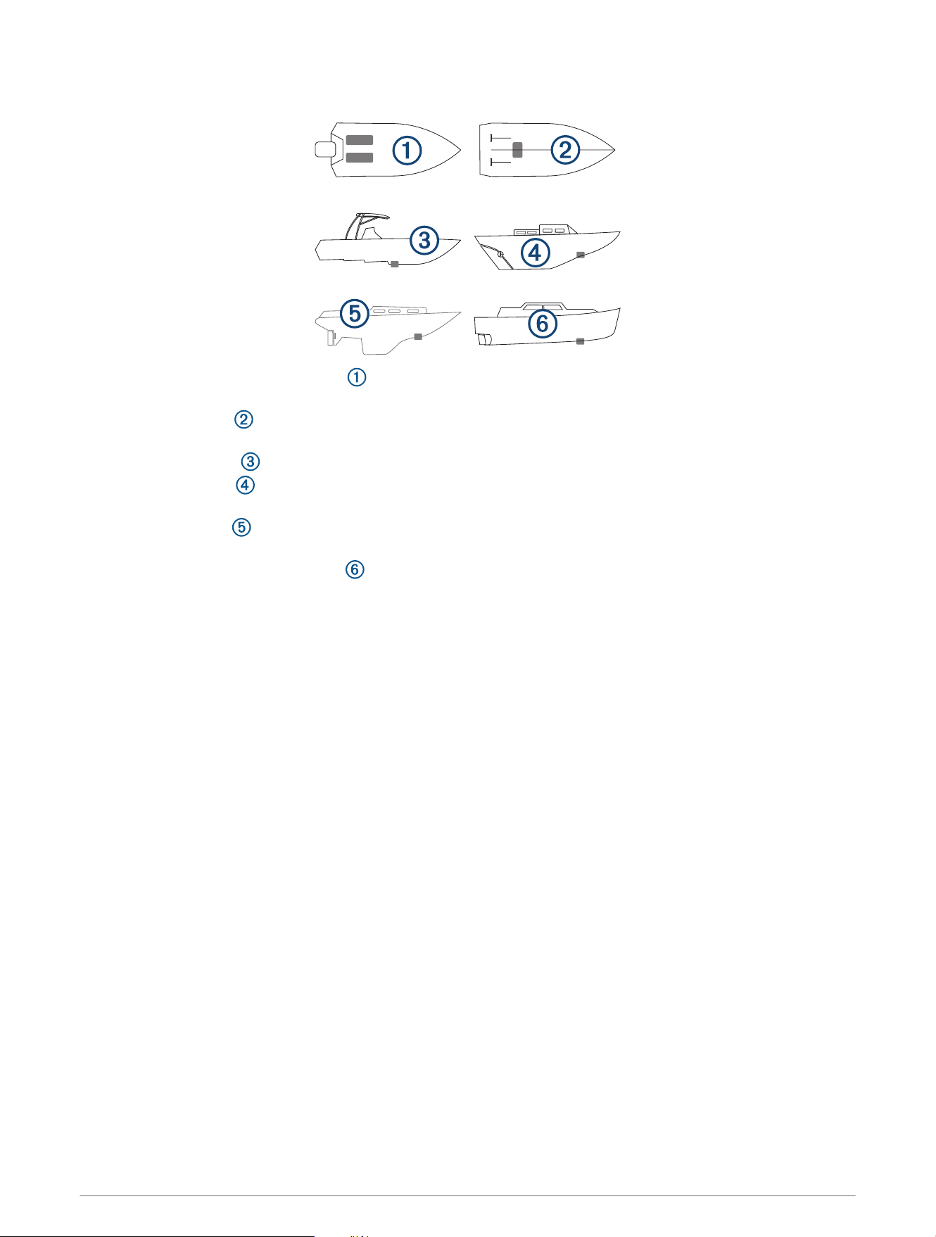
• On outboard and sterndrive vessels , the transducer should be mounted in front of and close to the engine
or engines.
• On inboard vessels , the transducer should be mounted in front of and far away from the engine propeller
and shaft.
• On step-hull vessels , the transducer should be mounted in front of the first step.
• On full-keel vessels , the transducer should be mounted at a slight angle that aims at the bow, parallel to
the centerline.
• On fin-keel vessels , the transducer should be mounted from 25cm to 75cm (from 10to 30in.) in front of
the keel and a maximum of 10cm (4in.) to the side of the centerline.
• On vessels with displacement hulls , the transducer should be mounted approximately
1
/
3
aft of the
waterline length of the vessel from the bow, and from 150 to 300mm (from 6 to 12in.) to the side of the
centerline.
• The transducer should be mounted parallel to the bow-stern axis of your vessel.
• The transducer should not be mounted behind strakes, struts, fittings, water intake or discharge ports, or
anything that creates air bubbles or causes the water to become turbulent.
The transducer must be in clean (non-turbulent) water for optimal performance.
• The transducer should not be mounted in a location where it might be jarred when launching, hauling, or
storing.
• On single-drive boats, the transducer must not be mounted in the path of the propeller.
The transducer can cause cavitation that can degrade the performance of the boat and damage the propeller.
• On twin-drive boats, the transducer should be mounted between the drives, if possible.
3
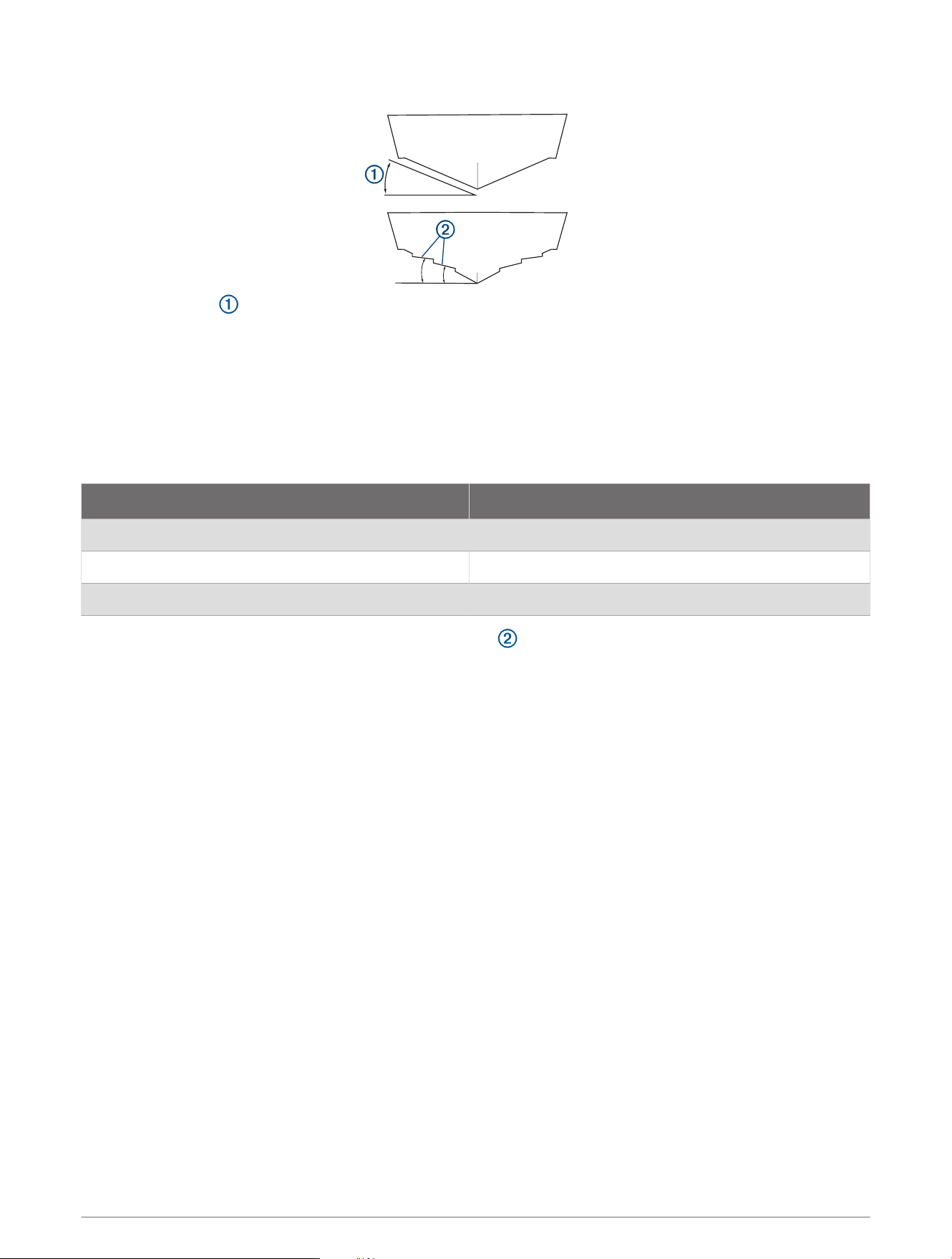
Deadrise Angle
The deadrise angle is the measurement of the angle between a horizontal line and the outer hull at a single
point.
These transducers are available in a selection of pre-configured angles from 0 to 20 degrees. For optimal
performance, it is critical that the transducer angle you purchase is as close as possible to the deadrise angle at
the installation location.
Before drilling any holes in the hull, you should verify the deadrise angle at the installation location by measuring
with a smartphone application, an angle finder, a protractor, or a digital level. You can also ask your boat
manufacturer for the deadrise of a specific point on your boat hull. You should confirm that you have purchased
the correct transducer for the mounting location by referring to this table.
Deadrise Angle Measurement Appropriate Transducer Model
From 0 to 5 degrees 0 degree
From 6 to 16 degrees 12 degree
From 17 to 24 degrees 20 degree
NOTE: Your vessel's hull may have several deadrise angles depending on the hull shape. Be sure to measure
the deadrise angle at the selected installation location.
4
Preparing the Hull
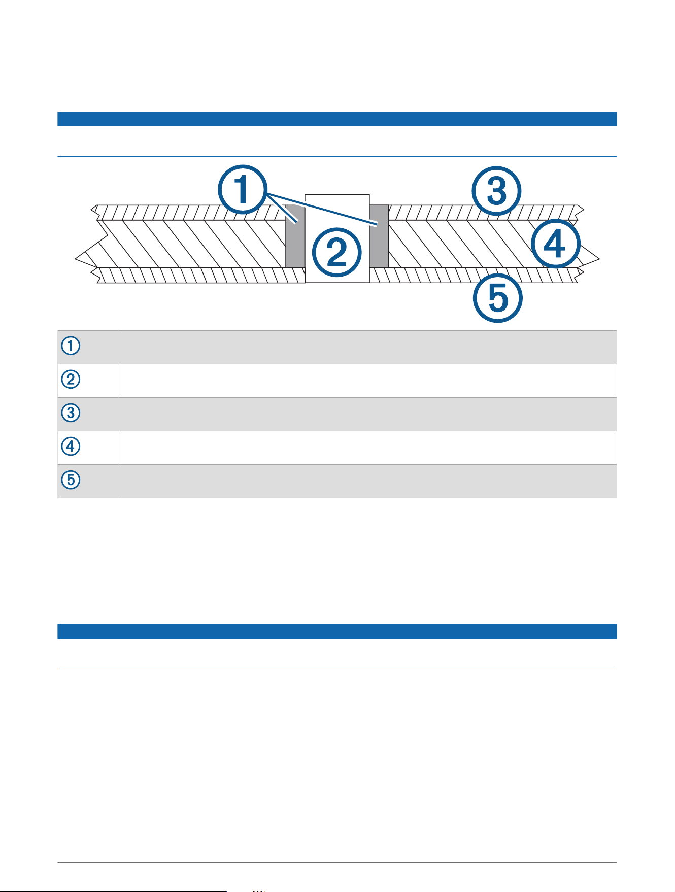
Preparing a Cored-Fiberglass Hull
NOTICE
If the core of a cored-fiberglass hull is not sealed properly, water may seep into the core and severely damage
the boat.
Fiberglass or casting epoxy (not included)
Cylinder spacer
Inner fiberglass skin
Core
Outer fiberglass skin
1 From outside the hull, drill a 3mm (
1
/
8
in.) pilot hole at the transducer location.
2 Place masking tape over the pilot hole and surrounding area outside the hull to reduce cracking of the gel
coat.
3 Use a utility knife to cut a hole in the tape over the pilot hole.
4 From outside the hull, use a 73 mm (2
7
/
8
in.) hole saw to cut the transducer hole completely through the
hull.
5 From inside of the hull, use a slightly larger hole saw to cut only the inner fiberglass skin and core.
NOTICE
You must take care not to cut the outer fiberglass skin with the larger hole saw, so that you can seal the core
properly.
6 Seal the core inside the hull using either fiberglass (Sealing the Core with Fiberglass, page5) or casting
epoxy (Sealing the Core with Fiberglass, page5).
Sealing the Core with Fiberglass
1 From inside the boat, coat a layer of fiberglass cloth with fiberglass resin, and place it inside the hole to seal
the core.
2 Add layers of fiberglass cloth and resin until the hole is the correct diameter of 73 mm (2
7
/
8
in.).
3 After the fiberglass has hardened, sand and clean inside and around the hole.
The cored-fiberglass hull is now prepared, and you can complete the transducer installation.
5
Sealing the Core with Casting Epoxy
To properly seal the core with casting epoxy, you must create a cylinder with an outer diameter of 73 mm (2
7
/
8
in.) to act as a spacer as the epoxy sets.
1 Coat a 73 mm (2
7
/
8
in.) cylinder with wax.
2 Insert the cylinder in the hole through the outer skin, and tape it in place on the outside of the boat.
3 Fill the space between the cylinder the core with casting epoxy.
4 After the epoxy has hardened, remove the cylinder, and sand and clean inside and around the hole.
The cored-fiberglass hull is now prepared, and you can complete the transducer installation.
Preparing a Solid Fiberglass or Metal Hull
1 From outside the hull, drill a 3mm (
1
/
8
in.) pilot hole at the transducer location.
2 On a fiberglass hull, place masking tape over the pilot hole and surrounding area outside the hull to reduce
cracking of the gel coat.
3 Use a utility knife to cut a hole in the tape over the pilot hole.
4 From outside the hull, cut the transducer hole using a hole saw of the appropriate size for your hull material:
• For a metal hull, use a 75 mm (3in.) hole saw.
• For a solid fiberglass hull, use a 73 mm (2
7
/
8
in.) hole saw.
5 Sand and clean the inside of the hole and the area around the hole.
Installing the Transducer
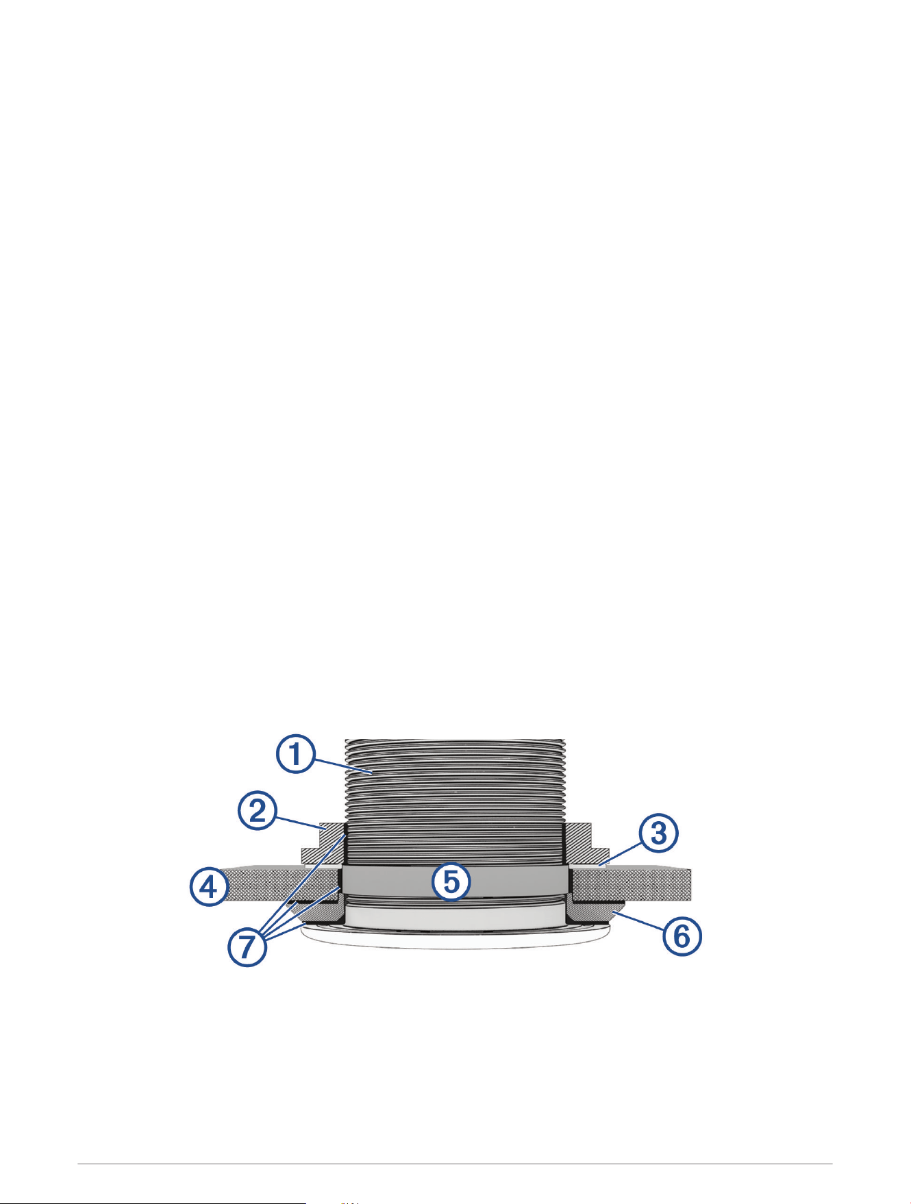
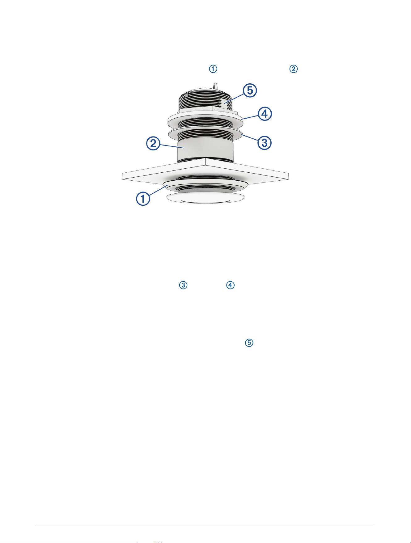
Applying Marine Sealant to a Thru-hull Transducer
When installing the transducer, you must apply marine sealant to the water path to ensure a tight, waterproof
seal between the transducer and hull.
1 When instructed in the installation procedure, apply a 2mm (
1
/
16
in.) layer of marine sealant to the inner
flange of the transducer housing where it contacts the hull.
2 Apply a layer of marine sealant along the threads of the transducer housing to fill the space between the
threads and the hull.
NOTE: The sealant on the threads should extend about 6mm (
1
/
4
in.) above the inside of the hull to seal the
hull and secure the hull nut.
6
Transducer threads
Hull nut
Washer (when installing in a metal hull)
Hull
Thread isolator (when installing in a metal hull)
Hull isolator (when installing in a metal hull)
Marine sealant
Installing the Transducer in a Fiberglass Hull
NOTICE
When installing a transducer in a fiberglass hull, avoid over-tightening the nut to prevent damaging the hull.
NOTE: It is recommended that two installers complete these instructions, with one positioned outside the boat
and one inside the boat.
1 Apply marine sealant to the transducer (Applying Marine Sealant to a Thru-hull Transducer, page6).
2 From outside the hull, insert the transducer through the mounting hole, using a twisting motion to squeeze
out excess sealant.
3 From inside the hull, place the nylon washer and hull nut onto the stem.
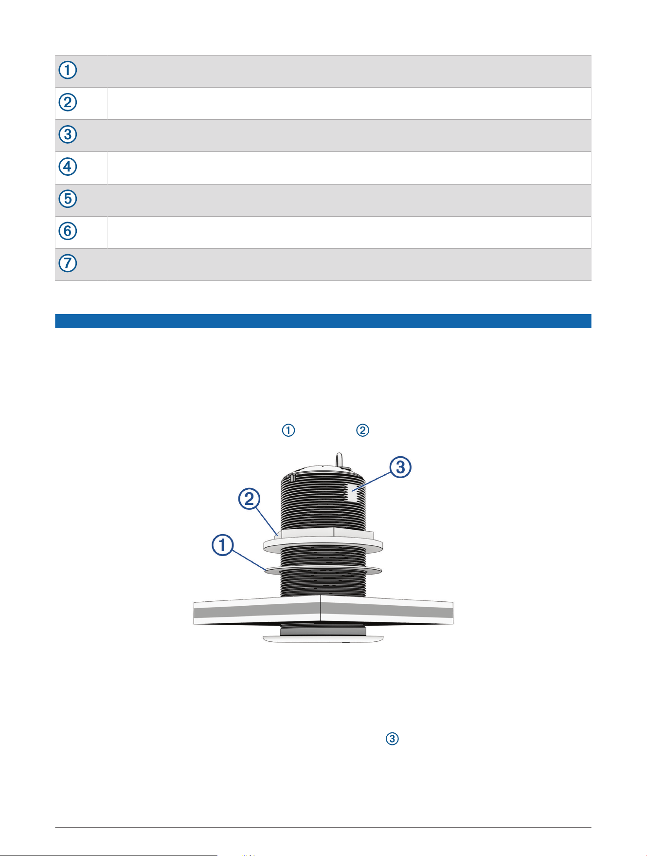
4 From inside the hull, rotate the transducer as needed until the arrow on the top points to the keel of the boat.
The arrow on the top of the transducer must point to the keel so the internal angle aligns with the deadrise
angle of the boat.
5 Using a 75 mm wrench or adjustable wrench, tighten the hull nut to secure the transducer in the hull.
NOTE: You can hold the transducer stem steady while tightening the hull nut using slip-joint pliers, a 67mm
wrench, or an adjustable wrench on the flat areas without threads .
Do not over-tighten the nut.
6 Before the sealant hardens, remove all excess sealant on the outside of hull to ensure smooth water flow
over the transducer.
7
Installing the Transducer in a Metal Hull
NOTE: It is recommended that two installers complete these instructions, with one positioned outside the boat
and one inside the boat.
1 Before applying marine sealant, place the hull isolator and the thread isolator on the transducer.
2 From outside the hull, insert the transducer through the mounting hole and hold it in place.
3 Using a knife or scissors, cut the thread isolator so it is flush with the surface of the inner hull.
NOTE: The thread isolator must be flush with the inner surface of the hull so it does not restrict the hull nut
when tightening it.
4 Remove the transducer from the mounting hole, and apply marine sealant to the transducer and isolators
(Applying Marine Sealant to a Thru-hull Transducer, page6).
5 Insert the transducer through the mounting hole, using a twisting motion to squeeze out excess sealant.
6 From inside the hull, place the nylon washer and hull nut onto the stem.
7 From inside the hull, rotate the transducer until the arrow on the top points to the keel of the boat.
The arrow on the top of the transducer must point to the keel so the internal angle aligns with the deadrise
angle of the boat.
8 Using a 75 mm wrench or adjustable wrench, tighten the hull nut to secure the transducer in the hull.
NOTE: You can hold the transducer stem steady while tightening the hull nut using slip-joint pliers, a 67mm
wrench, or an adjustable wrench on the flat areas without threads .
9 Before the sealant hardens, remove all excess sealant on the outside of the hull to ensure smooth water flow
over the transducer.
8

Routing and Connecting the Transducer Cable
NOTICE
To prevent damage to the cable and the transducer, do not use the cable to pick up or pull the transducer.
Unless you are connecting the transducer to a sonar black box that requires bare-wire connections, you should
not cut or splice the transducer cable. Cutting the transducer cable other than what is needed to connect to a
sonar black box may void your warranty.
If the transducer cable is not long enough to reach the chartplotter or sonar black box, you can purchase an
extension cable from your Garmin dealer or buy.garmin.com.
1 Route and connect the transducer cable to the chartplotter or sonar black box while taking these
precautions.
• Route the cable away from other wiring and the engine(s) to prevent possible interference with the sonar
signal.
• Route the cable so it is not pinched by other equipment.
• Use grommets to protect the cable if it passes through the bulkhead or other parts of the boat.
• Use zip ties or other suitable fastening equipment to secure the cable where necessary to protect it from
damage. You should avoid over-tightening zip ties and compressing the cable.
2 Connect the transducer cable to the appropriate port on the chartplotter or sonar black box.
3 Tighten the locking ring on the cable connector to secure it.
Maintenance
Testing the Installation
NOTICE
You should check your boat for leaks before you leave it in the water for an extended period of time.
Because water is necessary to carry the sonar signal, the transducer must be in the water to work properly. You
cannot get a depth or distance reading when out of the water. When you place your boat in the water, check for
leaks around any screw holes that were added below the water line.
Anti-Fouling Paint
To prevent corrosion on metal hulls and to slow the growth of organisms that can affect a vessel's performance
and durability on both metal and fiberglass hulls, you should apply a water-based anti-fouling paint to the hull of
your vessel every six months.
NOTICE
Never apply ketone-based anti-fouling paint to your vessel, because ketones attack many types of plastic and
could damage or destroy your transducer.
9

Cleaning the Transducer
CAUTION
To avoid possible transducer damage or personal injury, use care when cleaning the transducer, particularly
when attempting to remove severe fouling.
NOTICE
To prevent permanent damage to the surface of the transducer, do not use solvents such as mineral spirits,
acetone, Methyl Ethyl Ketone (MEK), or similar products when cleaning. Do not use a power sander or pressure
washer to clean the transducer.
Aquatic fouling accumulates quickly and can reduce your device's performance.
1 Remove the fouling with a soft cloth and mild detergent.
2 If the fouling is severe, use a non-metallic scouring pad or putty knife to remove growth.
3 Wipe the transducer dry.
Specifications
All Models
Specification Measurement
Frequencies
1
From 85 to 165kHz
Beamwidth From 24 to 16degrees
Operating temperature range From 0° to 50°C (from 32° to 122°F)
Storage temperature range From -40° to 70°C (from -40° to 158°F)
Dimensions
Diameter (threads): 70mm (2.76in.)
Diameter (flange): 94mm (3.70in.)
Height: 146mm (5.75in.)
Cable length 15m (50ft.)
GT12M-THF
Specification Measurement
Housing material Bronze
Weight 2.6kg (5.7lb.)
Maximum depth
2
Freshwater: 365m (1,200ft.)
Saltwater: 245m (800ft.)
Transmit power 350W
1
Dependent upon the chartplotter, fishfinder, or sounder model.
2
Dependent upon water conditions.
10
GT15M-THF
Specification Measurement
Housing material Stainless steel
Weight 2.3kg (5.1lb.)
3
Maximum depth
2
Freshwater: 580m (1,900ft.)
Saltwater: 365m (1,200ft.)
Transmit power 600W
Limited Warranty
The Garmin standard limited warranty applies to this accessory. For more information, go to garmin.com
/support/warranty.
Australian Purchases: Our goods come with guarantees that cannot be excluded under the Australian
Consumer Law. You are entitled to a replacement or refund for a major failure and for compensation for any
other reasonably foreseeable loss or damage. You are also entitled to have the goods repaired or replaced if the
goods fail to be of acceptable quality and the failure does not amount to a major failure. The benefits under our
Limited Warranty are in addition to other rights and remedies under applicable law in relation to the products.
Garmin Australasia, 30 Clay Place, Eastern Creek, NSW 2766, Australia. Phone: 1800 235 822.
連絡地址
製造銷售:台灣國際航電股份有限公司
聯絡地址:新北市汐止區樟樹二路 68 號
電 話:(02)2642-8999
客服專線:(02)2642-9199
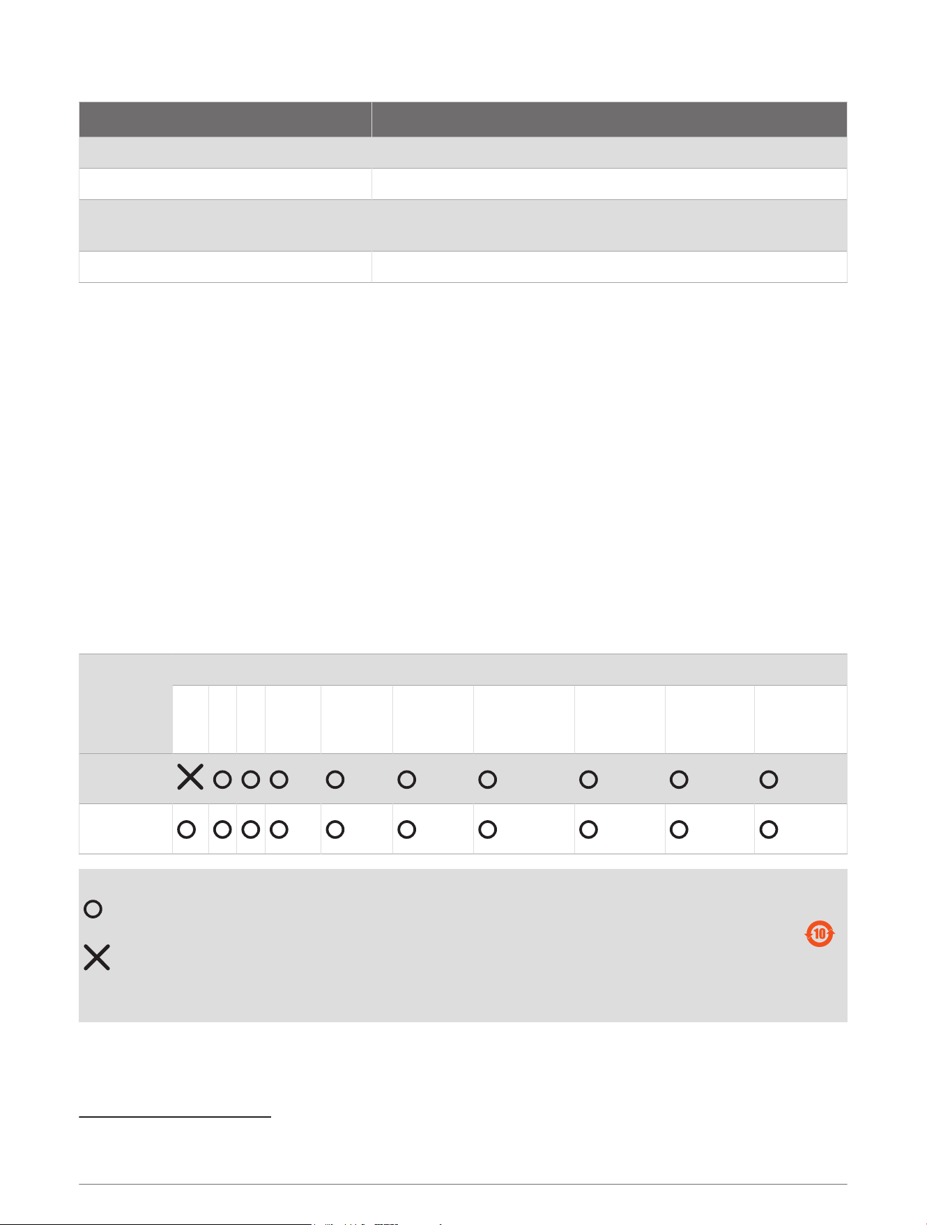
物質宣言
部件名称
有毒有害物质或元素
铅 汞 镉 六价铬 多溴联苯
多溴二苯
醚
邻苯二甲酸
二(2-乙基己)
酯
邻苯二甲酸
丁苄酯
邻苯二甲酸
二丁酯
邻苯二甲酸
二异丁酯
塑料和橡胶
零件
塑料和橡胶
零件
本表格依据 SJ/T11364 的规定编制。
: 代表此种部件的所有均质材料中所含的该种有害物质均低于
(GB/T26572) 规定的限量
: 代表此种部件所用的均质材料中, 至少有一类材料其所含的有害物质高于
(GB/T26572) 规定的限量
* 该产品说明书应提供在环保使用期限和特殊标记的部分详细讲解产品的担保使用条件。
产品
© 2023 Garmin Ltd. or its subsidiaries
Garmin
®
and the Garmin logo are trademarks of Garmin Ltd. or its subsidiaries, registered in the USA and other countries. These trademarks may not be used without the
express permission of Garmin.
3
If you are installing the transducer in a metal hull, the isolation components weigh an additional 27g (1oz.)
2
Dependent upon water conditions.
11

声纳探头
© 2023 Garmin Ltd. or its subsidiaries
support.garmin.com