Warning notices: Before using this product, please read this manual carefully and keep it for future reference.
The design and specifications are subject to change without prior notice for product improvement.
Consult with your dealer or manufacturer for details.
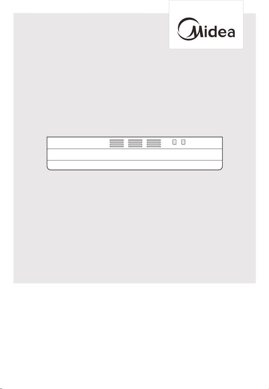
The diagram above is just for reference. Please take the appearance of the actual product as the standard.
USER MANUAL
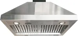
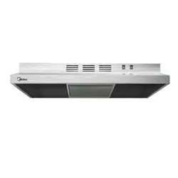
Cooker Hood
MVU30W2AST
THANK YOU LETTER
Thank you for choosing Midea! Before using your new Midea product, please read
this manual thoroughly to ensure that you know how to operate the features and
CONTENTS
0
02
1
09
19
20
22
23
23
24
THANK YOU LETTER
SAFETY INSTRUCTIONS
06
SPECIFICATIONS
07
PRODUCT OVERVIEW
PRODUCT INSTALLATION
OPERATION INSTRUCTIONS
CLEANING AND MAINTENANCE
TROUBLE SHOOTING
TRADEMARKS, COPYRIGHTS AND LEGAL STATEMENT
DISPOSAL AND RECYCLING
DATA PROTECTION NOTICE
01
Danger
Warning of electrical voltage
This symbol indicates that there is a danger to life and health of
persons due to voltage.
Warning
The signal word indicates a hazard with a medium level of risk which, if
not avoided, may result in death or serious injury.
Caution
The signal word indicates a hazard with a low degree of risk which, if
not avoided, may result in minor or moderate injury.
Attention
The signal word indicates important information (e.g. damage to
property), but not danger.
Observe instructions
This symbol indicates that a service technician should only operate and
maintain this appliance in accordance with the operating instructions.
Read these operating instructions carefully and attentively before using/commissioning the
unit and keep them in the immediate vicinity of the installation site or unit for later use!
Intended Use
Explanation of Symbols
SAFETY INSTRUCTIONS
02
The following safety guidelines are intended to prevent unforeseen risks or damage from
unsafe or incorrect operation of the appliance. Please check the packaging and appliance
on arrival to make sure everything is intact to ensure safe operation. If you find any
damage, please contact the retailer or dealer. Please note modifications or alterations to
the appliance are not allowed for your safety concern. Unintended use may cause
hazards and loss of warranty claims.
This symbol indicates that there are dangers to the life and health of
persons due to extremely flammable gas.
WARNING
TO REDUCE THE RISK OF FIRE,
ELECTRIC SHOCK, OR INJURY TO
PERSONS, OBSERVE THE FOLLOWING:
Use this unit only in the manner
intended by the manufacturer. If you
have questions, contact the
manufacturer.
Before servicing or cleaning the unit,
switch power off at service panel and
lock service panel disconnecting
means to prevent power from being
switched on accidentally. When the
service disconnecting means cannot
be locked, securely fasten a prominent
warning device, such as a tag, to the
service panel.
Installation Work and Electrical Wiring
Must Be Done By Qualified Person(s)
In Accordance With all Aplicable
Codes & Standards, Including
Fire-rated Construction.
Sufficient air is needed for proper
combustion and exhausting of gases
through the flue (Chimney) of fuel
burning equipment to prevent
back-drafting. Follow the heating
equipment manufacturers guideline
and safety standards such as those
published by the National Fire
Protection Association (NFPA), the
American Society for Heating,
Refrigeration and Air Conditioning
Engineers (ASHRAE), and the local
code authorities.
When cutting or drilling into wall or
ceiling, do not damage electrical
wiring and other hidden utilities.
Ducted systems must always be
vented to the outdoors.
A.
B.
C.
D.
E.
F.
CAUTION
To reduce risk of fire and to properly
exhaust air, do not vent exhaust air
into spaces within walls, ceilings, attics,
crawl spaces, or garages.
WARNING
This symbol alerts you to situations
that may cause serious body harm,
death or property damage.
Save these instructions for future references.
Approved for residential appliances.
For residential use only.
Do not attempt to install or operate your
appliance until you have read the safety
precautions in this manual.
Safety items throughout this manual are
labeled with a WARNING or CAUTION based
on the risk type.
This is the safety alert symbol. It is used
to alert you to potential personal injury
hazards. Obey all safety messeges that
follow this symbol to avoid possible injury or
death.
CAUTION
CAUTION indicates a potentially
hazardous situation which, if not
avoided, may result inminor or
moderate injury.
IMPORTANT
IMPORTANT indicates installation,
operation,maintenance or valuable
information that is not hazard related.
CAUTION
FOR GENERAL VENTILATING USE
ONLY. DO NOT USE TO EXHAUST
HAZARDOUS OR EXPLOSIVE
MATERIALS OR VAPORS.
WARNING
TO REDUCE THE RISK OF FIRE, USE
ONLY METAL DUCT WORK.
Install this hood in accordance with all
requirements specified.
03
Important Safety Instructions
TO REDUCE THE RISK OF A RANGE
TOP GREASE FIRE.
Never leave surface units unattended
at high settings. Boilovers cause
smoking and greasy spillovers that
may ignite. Heat oils slowly on low or
medium settings.
Always turn hood ON when cooking
at high heat or when flambeing food
(l.e. Crepes Suzette, Cherries Jubilee,
Peppercorn Beef Flambe).
Clean ventilating fans frequently.
Grease should not be allowed to
accumulate on fan or filter.
Use proper pan size. Always use
cookware appropriate for the size of
the surface element.
a)
b)
c)
d)
WARNING
TO REDUCE THE RISK OF INJURY TO
PERSONS, IN THE EVENT OF A RANGE
TOP GREASE FIRE, OBSERVE THE
FOLLOWING:
SMOTHER FLAMES with a close-fitting
lid, cookie sheet, or other metal tray,
then turn off the gas burner or the
electric element. BE CAREFUL TO
PREVENT BURNS. If the flames do not
go out immediately, EVACUATE AND
CALL THE FIRE DEPARTMENT.
NEVER PICK UP A FLAMING PAN-
you may be burned.
DO NOT USE WATER, including wet
dishcloths or towels - a violent steam
explosion will result.
Use an extinguisher ONLY if:
1)You know you have a class ABC
extinguisher,and you already know
how to operate it.
2)The fire is small and contained in the
area where it started.
3)The fire department is being called.
4)You can fight the fire with your back
to an exit.
a)
b)
c)
d)
OPERATION
Always leave safety grills and filters in
place.Without these components,
operating blowers could catch onto
hair, fingers and loose clothing.
The manufacturer declines all responsi-
bility in the event of failure to observe
the instructions given here for
installation,maintenance and suitable
use of the product. The manufacturer
further declines all responsibility
for injury due to negligence and the
warranty of the unit automatically
expires due to improper maintenance.
WARNING
NOT SUITBLE FOR USE WITH
SOLID-STATE SPEED CONTROLS.
WARNING
To Reduce The Risk Of Fire Or Electric
Shock, Do Not Use This Hood With Any
External Solid State Speed Control
Device.
WARNING
WARNING
NE CONVIENT PAS À DES RÉGULA-
TEURS DE VITE SSE À SEMI-CONDUC-
TEURS.
AVERTISSEMENT
Use only with rangehood cord-connec-
tion kits that have been investigated
and found acceptable for use with this
model rangehood.
04
Important Safety Instructions
READ AND SAVE THESE
INSTRUCTIONS
05
Important Safety Instructions
List of Materials
ELECTRICAL REQUIREMENTS
Observe all governing codes and
ordinances.
GROUNDING INSTRUCTIONS
This appliance must be grounded. In the
event of an electrical short circuit, ground-
ing reduces the risk of electric shock by
providing an escape wire for the electric
current. This appliance is equipped with a
cord having a grounding wire with a
grounding plug. The plug must be plugged
into an outlet that is properly installed and
grounded.
WARNING-Improper grounding can
result in a risk of electric shock.
Consuit a qualified electrician if the
grounding instructions are not
completely understood, or if doubt
exists as to whether the appliance is
properly grounded.
Do not use an extension cord. If the
power supply cord is too short, have a
qualified electrician install an outlet near
the appliance.
Ensure that the electrical installation is
adequate and in conformance with
National Electrical Code, ANSI/NFPA 70
(latest edition), or CSA Standards
C22.1-94, Canadian Electrical Code, Part
1 and C22.2 No. 0-M91 (latest edi-tion)
and all local codes and ordinances.
If codes permit and a separate ground
wire is used, it is recommended that a
qualified electrician determine that the
ground path is adequate.
A copy of the above code standards
can be obtained from:
Tools/Materials required
Wire nuts
Metal duct length to suit installation
Vent clamps/duct tape as required
UL listed or CSA approved ” strain relief
Remove the protective film covering the
product before putting into operation.
5/64” drill bit for cabinet pilot holes
Pencil
Wire cutter / stripper
Measuring tape
Caulking gun and weatherproof caulking
compound
Flat-blade screwdriver
Phillips screwdriver
Saber or keyhole saw
Safety glasses
Gloves
●
●
●
●
●
●
●
●
●
●
●
●
●
●
For cabinets with recessed bottoms
Two - 2” (5.1 cm) wide filler strips.
Length and thickness determined by
recess dimensions.
Four flat head wood screws or
machine screws with washers and nuts
(to attach filler strips).
●
●
LIST OF MATERIALS
Parts included in your hood
3 1/4" x 10" Rectangular vent damper
2 - Grease filters
Use and Care / Installation Manual
Mounting screw kit
2 - 0.49 * 5.0 cm mounting screws
4 - 0.50 * 1.9 cm mounting screws
6 - 0.40 * 0.8 cm rectangular vent damper
screws 2 - plastic wall anchores
●
●
●
●
CAUTION
Remove carton carefully. Wear gloves
to protect against sharp edges.
National Fire Protection Association
One Batterymarch Park
Quincy, MA 02269
CSA International
8501 East Pleasant Valley Road
Cleveland, OH 44131-5575

SPECIFICATIONS
MVU30W2ASTProduct Model
Voltage
Rated Power
Lighting Power
Motor Power
Air flow
Noise
120V~/60Hz
70 W
E26 LED MAX 9W
70 W
200CFM
≤72 dB(A)
06
List of Materials
A 120 volt, 60 Hz., AC only, 15-amp,
fused electrical circuit is required.
If the house has aluminum wiring, follow
the procedure below:
Follow the electrical connector
manufacturer’s recommended
procedure. Aluminum/copper
connection must conform with local
codes and industry accepted wiring
practices.
1. Connect a section of solid copper
wire to the pigtail leads.
2. Connect the aluminum wiring to
the added section of copper wire
using special conectors and/or tools
designed and UL listed for joining
copper to aluminum.
●
●
Wire sizes and connections must
conform with the rating of the appli-
ance as specified on the model/serial
rating plate.
The model/serial plate is located on the
left side of the range hood.
Wire sizes must conform to the
requirements of the National Electrical
Code, ANSI/NFPA 70 (laest edition), or
CSA Standards C22. 1-94, Canad
Electrical Code, Part 1 and C22.2 No.
0-M91 (latest edition) and all local
codes and ordinances.
●
●
PRODUCT OVERVIEW
07
●
●
●
●
It is the installer’s responsibility to comply
with installation clearances.
Range hood location should be away from
strong draft areas, such as windows, doors
and strong heating vents.
Cabinet opening dimensions that are shown
must be used. Given dimensions provide
minimum clearance.
Grounded electrical outlet is required. See
“Electrical Requirements” section.
All openings in ceiling and wall where
canopy hood will be installed must be
sealed.
Important
Observe all governing codes and ordinances.
The installation of this range hood must
conform to the Manufactured Home Construc-
tion Safety Standards, Title 24 CFR, Part 328
(formerly the Federal Standard for Mobile
Home Construction and Safety, Title 24, HUD,
Part 280) or when such standard is not applica-
ble, the stan-dard for Manufactured Home
Installation 1982 (Manu-factured Home Sites,
Communities and Setups) ANSI A225.1/NFPA
501A, or latest edition, or with local codes.
24''(61.0 cm) min. for electric
cooking surfaces;
27''(68.6 cm) min. for gas cooking
surfaces
30''(76.2 cm) suggested max.
30''(76.2 cm) min. cabinet
opening width for 30'' (76.2 cm)
models and 36''(91.4 cm) min.
cabinet width for 36''(91.4 cm)
models.
36''(91.4 cm) base cabinet height
For Mobile Home Installations
Cabinet Dimensions
A
B
C
A.
B.
C.
Product dimensions
unit:inch
08
(706mm)27
13
16
7
7
(230mm)
8
24
(620.75mm)
7
16
1
(43mm)
11
16
9
(251mm)
7
8
3
(80mm)
1
8
5 (143mm)
5
8
12
1
(306mm)
16
18”(458mm)
30”(760mm)
6 (176mm)
15
16
(225mm)
8
7
8
9 (240mm)
7
16
(200CFM Ducted version) (100CFM Ducted version)

Venting Requirements
●
●
●
Do not terminate the vent system into an attic or other enclosed area.
Do not use a 4'' (102 mm) laundry-type wall cap. Use metal vent only. Rigid metal
vent is recommended. Plastic or metal foil vent is not recommended.
The length of vent system and number of elbows should be kept to a minimum to
provide efficien performance.
09
●
●
●
●
●
●
●
Use no more than three 90° elbows.
Make sure there is a minimum of 24'' (610mm) of straight vent between the elbows if
more than 1 elbow is used.
Do not install 2 elbows together.
Use clamps or duct tape to seal all joints in the vent system.
The vent system at exit must have a cold air damper. Use caulking to seal exterior
wall or roof opening around the cap.
Best performances are reached with straight piping, without elbows and using
smooth pipe.
PRODUCT INSTALLATION
For the most efficient and quiet ope ation:
●
●
An additional back draft damper should be installed to minimize backward cold air
flow and a thermal b eak should be installed to minimize conduction of outside
tem-peratures as part of the vent system. The damper should be on the cold air side
of the thermal break.
The break should be as close as possible to where the vent system enters the heated
portion of the house.
Cold Weather Installations
●
Local building codes may require the use of makeup air systems when using ventila-
tion systems greater than specified CFM of air m vement. The specified CFM aries
from locale to locale. Consult your HVAC professional for specific equirements in your
area.
Makeup Air
●
Vent system can terminate either through the roof or wall. Use 3 '' x 10''(83 x 254
mm) rectangular with a maximum vent length of 35 ft (10.7 m) for vent system.
Venting Methods
10
Note
Flexible vent is not recommended. Flexible vent creates both back pressure and air
turbulence that greatly reduce performance.
Roof Venting Wall Venting
Calculating Vent System Length
To calculate the length of the system you need, add the equivalent feet (meters) for
each vent piece used in the system.
These directions are for rectangular vent installation only. If you choose to use round
rigid metal venting the minimum diameter to use is 8".
3¼ ” x 10” (83mm x 254mm) rectangular Vent System
Example Vent System
Vent Piece
3¼ ” x 10” (83 mm x 254 mm)
90° elbow
Maximum Recommended Length = 35 ft (10.7 m)
= 5.0 ft (1.5 m)
= 8.0 ft (2.4 m)
= 0.0 ft (0.0 m)
= 13.0 ft (3.9 m)
1 - 90° elbow
8 ft (2.4 m) straight
1 - wall cap
Length of 3¼” x 10”
(83 mm x 254 mm) system
3¼ ” x 10”
(83 mm x 254 mm)
elbow
5.0 ft
(1.5 m)
12.0 ft
(3.7 m)
0.0 ft
(0.0 m)
6 ft (1.8 m)
2 ft
(0.6 m)
Wall Cap
3¼ ” x 10” (83 mm x 254 mm)
flat elbow
3¼ ” x 10” (83 mm x 254 mm)
wall elbow
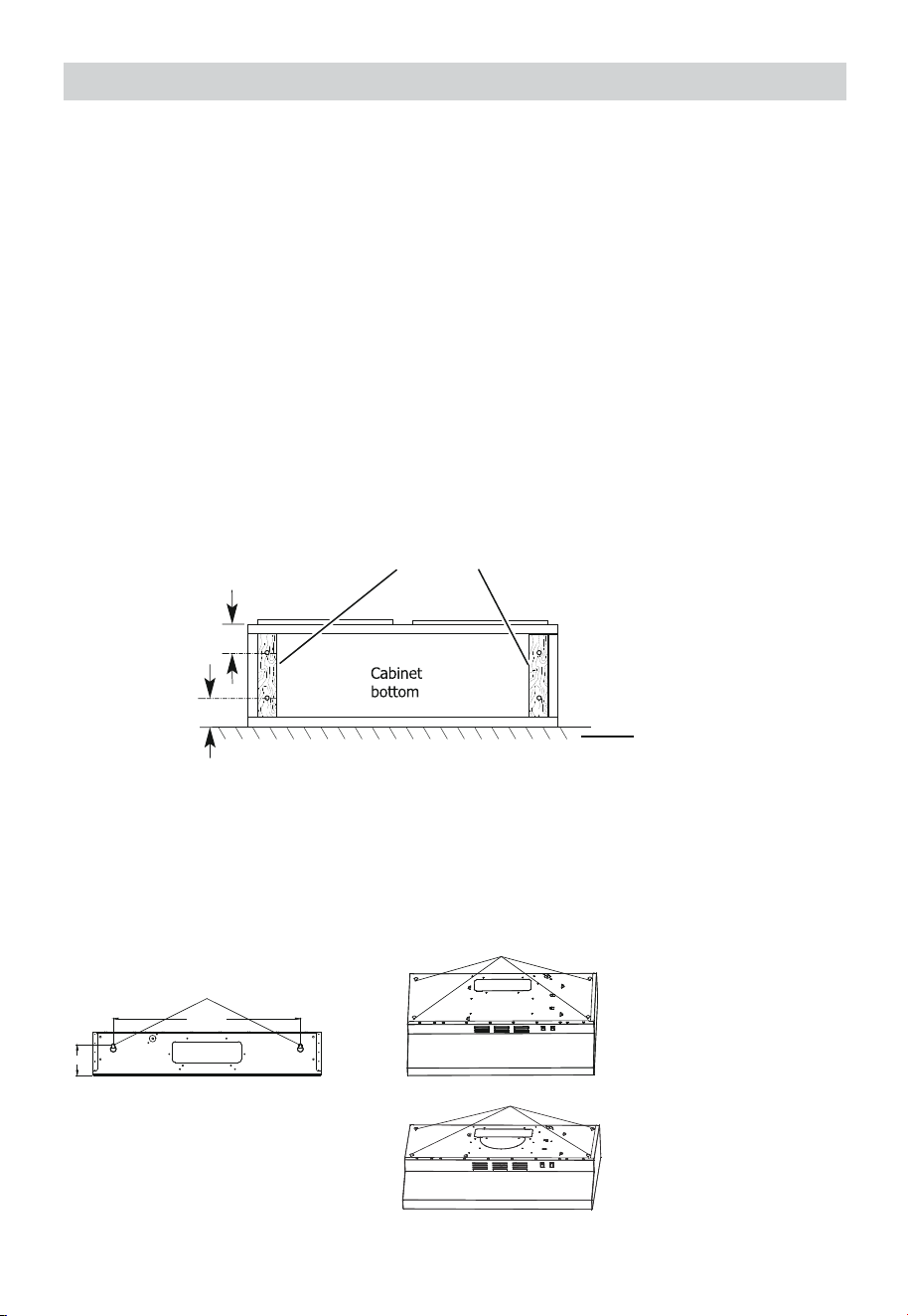
1.
2.
3.
4.
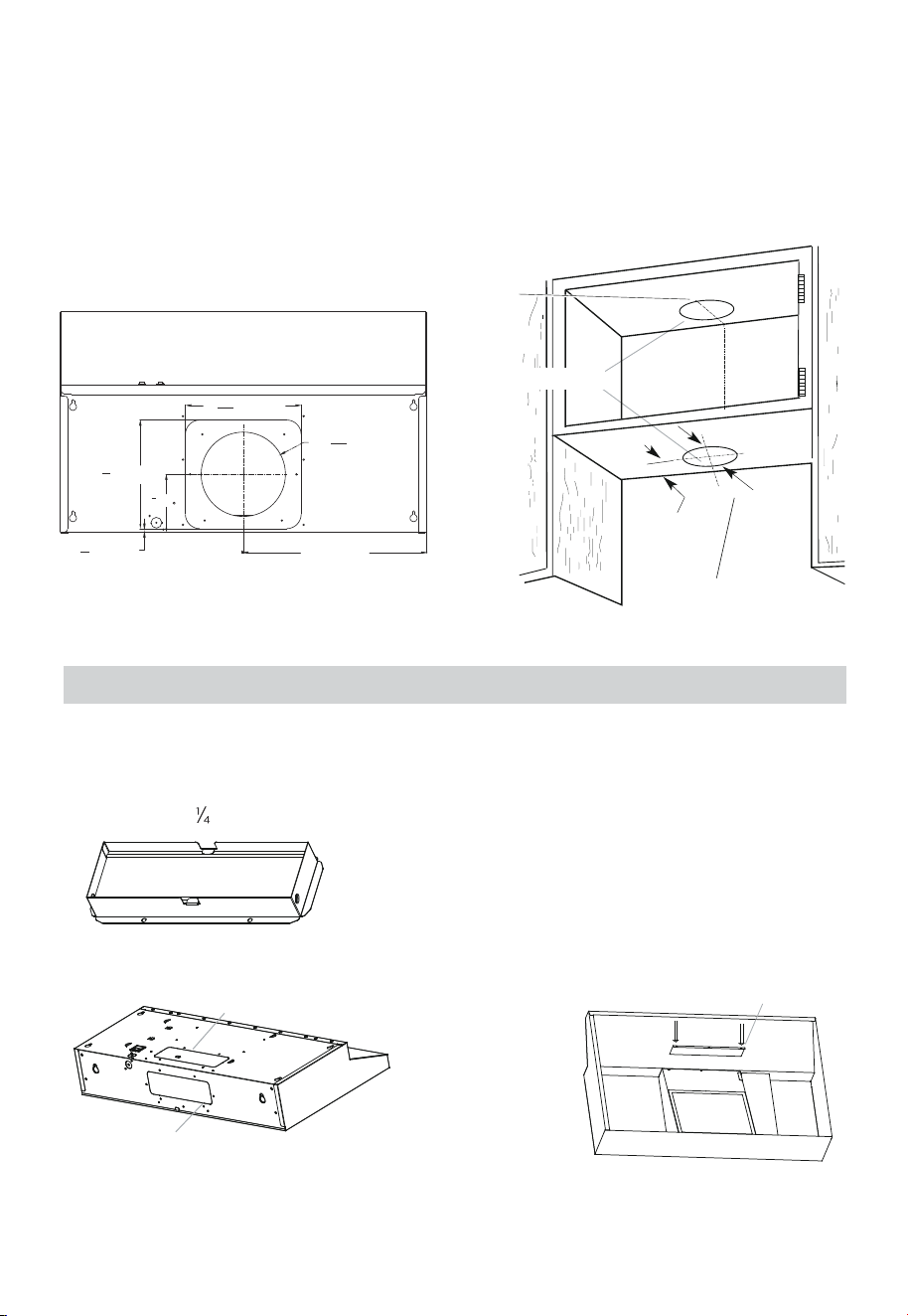
11
Disconnect power.
Select a flat surface for assembling the range hood. Place covering over that surface.
Lift the range hood and set it upside down onto cover ed surface.
If cabinet has recessed bot tom, add "two - 2” (51 mm) wide filler strips. Length and
thickness determined by recess dimensions. Four flat head wood screws or machine
screws wit h washers and nuts to attach filler strips in locations shown.
5.
Lift the range hood up under cabine and determine final location ycentering beneath
cabinet. Mark on the underside of cabinet the location of the 4 keyhole mounting
slots on the range hood (See slot dimensions on page 6). Mark rear mounting screw
hole locations.
Note
Prepare The Location
Before making cutouts, make sure there is proper clearance within the ceiling, wall or
cabinet.
Fitting material is provided to secure the hood to most types of walls and cabinets.
However, a qualified technician must verify suitability of the materials in accordance
with the type of wall and cabinet.
B
(100CFM)
(200CFM)
Set range hood aside on a covered surface.
A. Keyhole slot
3” (76 mm)
Wood filler strips
(recessed cabinet
bottoms only)
3” (76 mm)
Wall
A
B
620.7mm
100mm
12
6.
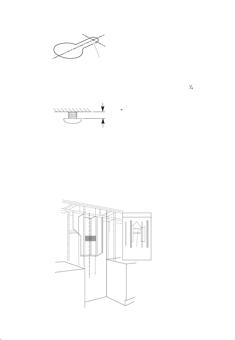
Use 5/64” drill bit and drill 4 pilot holes as shown for top range hood support.
NOTE: Make the drill holes on the thin area of the slot.
7.
Install the 4 - 5 mm x 19 mm mounting screws in pilot holes. Leave about ” (6.4
mm) space between screw heads and cabinet to slide range hood into place.
8.
Install framing for hood rear support
If drywall is present, using the rear mounting screw hole locations marked in the
previous step cut away enough drywall to expose 2 vertical studs at the rear
mounting screw holes locations. Install horizontal support at least 2” X 4” between
two wall studs at the rear mounting screw holes location. The horizontal support
must be flush with the room side of the studs. Use cleats behind both sides of the
support to secure to wall studs. Reinstall drywall and refinish. IMPORTANT –
Framing must be capable of supporting 100 lbs.
A
A. Drill pilot hole
1⁄4
(6.4 mm)
Centerline of
Installation
Space
View From
Cleats
Mounting
Support
8-1/2” min. opening for ductwork
Rear
2” x4” Min.
1.
Determine and clearly mark a vertical centerline on the wall and cabinet bottom.
Determine Wiring Hole Location
2.
Mark a line distance (A) from the right of the centerl ine on the underside of the
cabinet. Mark the point on this line that is from back wall. Drill a 1 ” (32 mm)
diameter hole (B) through the cabinet at this point.
3.
The actual size of the product is below, and the user is installed according to the
actual demand.
2.
The actual size of the product is below, and the user is installed according to the
actual demand.
To wire through top:
1.
Mark a line distance (A) from the right of the centerline on the underside of the wall.
Mark the point on this line that is fr om the underside of the cabinet. Drill a 1 ” (32
mm) diameter hole (B) through the rear wall at this point.
To wire through wall:
A
A
B
180mm
20mm
20mm
Centerline
A Centerline
A Centerline
180mm
A
B
13
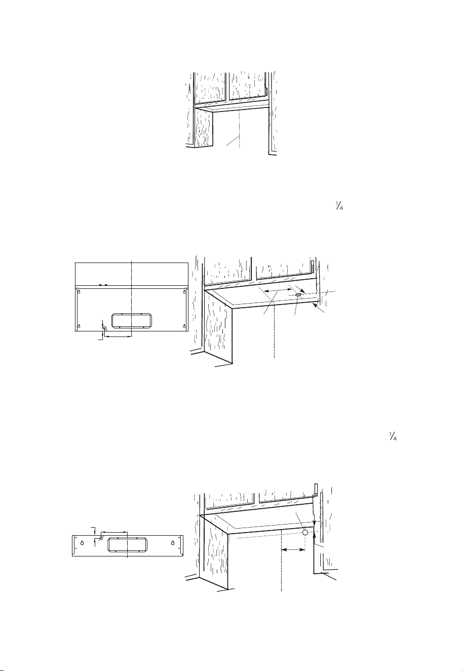
1.
cutout on the underside of cabinet top and bottom:
Mark lines from the back wall on the centerline of the underside of cabinet.
Mark lines to the right and left of the centerline on the underside of cabinet.
Use saber or keyhole saw to cut a rectangular opening for vent.
Repeat steps 1-3 for the underside of the top of the cabinet.
The actual size of the product is below, and the user is installed according to the
actual demand.
2.
3.
4.
5.
Roof Venting
1.
To make a 4 ” x 10 ” (108 mm x 267 mm) rectangle in the wall:
Mark lines from the back wall on the centerline of the underside of cabinet.
Mark lines to the right and left of the centerline on the underside of cabinet.
Use saber or keyhole saw to cut a rectangular opening for vent.
Repeat steps 1-3 for the underside of the top of the cabinet.
The actual size of the product is below, and the user is installed according to the
actual demand.
2.
3.
4.
5.
Wall Venting
From wall, not cabinet frame
Centerline
(Rectangle Ducted version)
10
5
8
(270mm)
9
7
8
(251mm)
3
(99mm)
3
0
16
(20mm)
1
32
5
13
4
11
(119mm)
16
4
5
16
(109.5mm)
1
8
7
8
(80mm)
(29.5mm)
Cabinet cutouts
Cabinet front
10
(270mm)
5
8
4
1
8
(105mm)
4
2
1
(114mm)
8
(251mm)
7
8
(24.8mm)
0
31
32
0
5
8
(15.4mm)
3
1
8
(80mm)
3
(98.8mm)
7
8
14
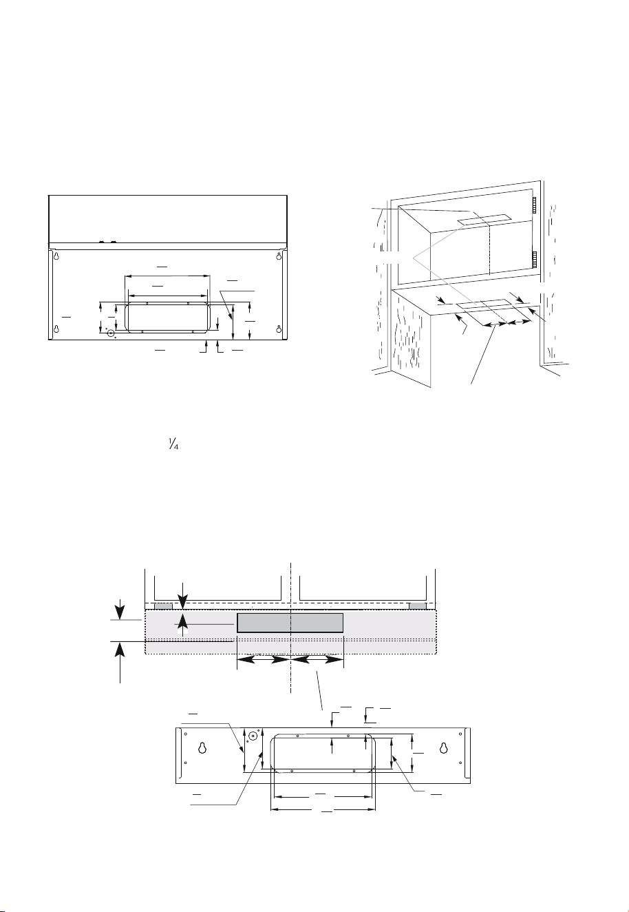
1.
2.
Install vent through the vent opening in upper cabinet.
Install Vent System
Detach the 3 ” x 10” (8.3 x 25.4 cm) rectangular vent damper from the package.
For roof installations, remove the top rectangular vent knockout A.For wall installa-
tions, remove the rear rectangular vent knockout B.
Install range hood (Ducted version).
Roof Venting(7" Circular interface)
To make 7 1/2"(190mm) rectangular cutout on the underside of cabinet topand bottom:
1.
Mark lines from the back wall on the centerline ofthe underside of cabinet.
Mark lines to the right and left of the centerline on the underside of cabinet. Use
saber or keyhole saw to cut a rectangular opening for vent.
Repeat steps 1-3 for the underside of the top of the cabinet.
The actual size of the product is below, and the user is installed according to the
actual demand.
2.
3.
4.
5.
Ø
(176mm)
4
0
16
5
(7.7mm)
6
16
15
(240mm)
9
16
7
(225mm)8
8
7
(120mm)
4
3
4
(380mm)
(Circular Ducted version)
Centerline
Cabinet cutouts
From wall, not cabinet
frame
C. Long baffle
when use A or B
air outlet, need
insert C baffle
A. Top rectangular knockout
B. Rear rectangular knockou
100CFM Ducted version
A. 3¼” x 10” (8.3 x 25.4 cm) rectangular vent damper
A
C
B
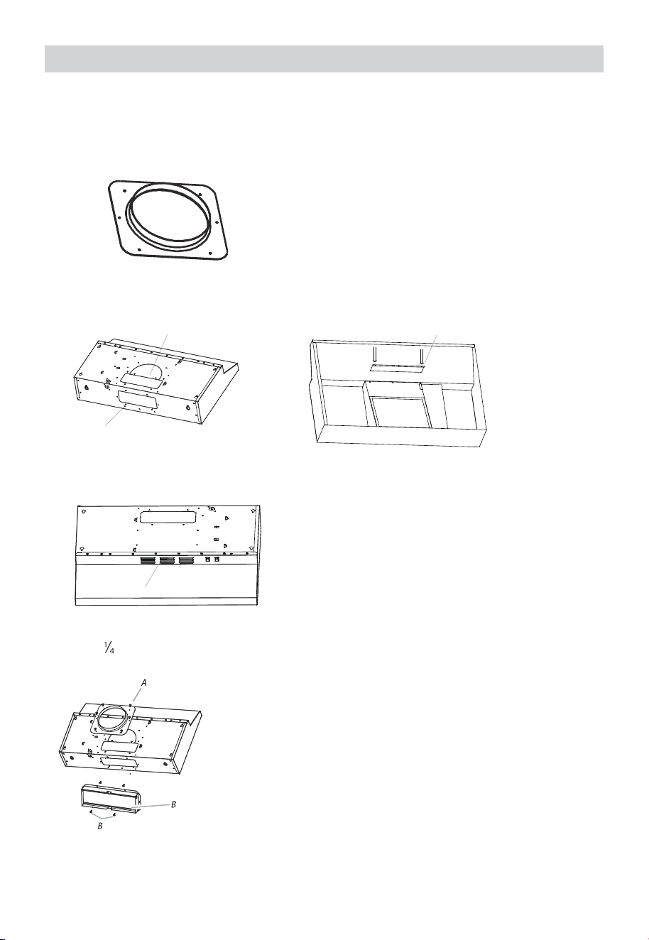
15
3.
Internal recycle air outlet
1.
2.
Remove the screws from the terminal box cover. Remove terminal box cover and
set aside.
A. Terminal box cover
B. Screw
Use D air outlet,retention A and B materials.
Vent Damper Installation
If a vent damper is installed with a wall cap with damper, check that they do not
interfere with each other. Remove the vent damper flap if they interfere.
Install 3 ” x 10” (8.3 x 25.4 cm) vent damper. Attach to range hood using the indicated
screws provided in hardware kit.
Power Supply Cable Installation
B
D
C
A
B
Install the 3¼” x 10” (8.3 x25.4 cm)
rectangular vent transition.
A. 3¼” x 10” (8.3 x 25.4 cm)
A
B
For direct wire installations, run the home power supply cable according to the
National Electric Code or CSA standards and local codes and ordinances.
Do not reconnect power until the installation is complete.
Before starting the installation, remove the vent grill and grease filters.
Note
16
If a vent damper is installed with a wall cap with damper, check that they do not
interfere with each other. Remove the vent damper flap if they interfere.
D
A
B
C
Install the 3¼” x 10” (8.3 x25.4 cm)
rectangular vent transition.
A. 3¼” x 10” (8.3 x 25.4 cm)
17
1.
Install vent through the vent opening in upper cabinet.
Install Vent System
200CFM Ducted version
2.
Detach the Ø7.08” (Ø 18cm) rectangular vent damper from the package.
For roof installations, remove the top rectangular vent knockout A. For wall installa-
tions, remove the rear rectangular vent knockout B.
INSTALL RANGE HOOD (Ducted version).
3.
Internal recycle air outlet.
Use D air outlet,retention A and B materials
A.Ø7.08” (Ø 18cm) rectangular vent damper
A. Top rectangular knockout
B. Rear rectangular knockout
C. Long baffle
Vent Damper Installation
nstall 3 ” x 10” (8.3 x 25.4 cm) vent damper. Attach to range hood using the
indicated screws provided in hardware kit.
A. Terminal box cover
B. Screw
A. Power supply knockout
18
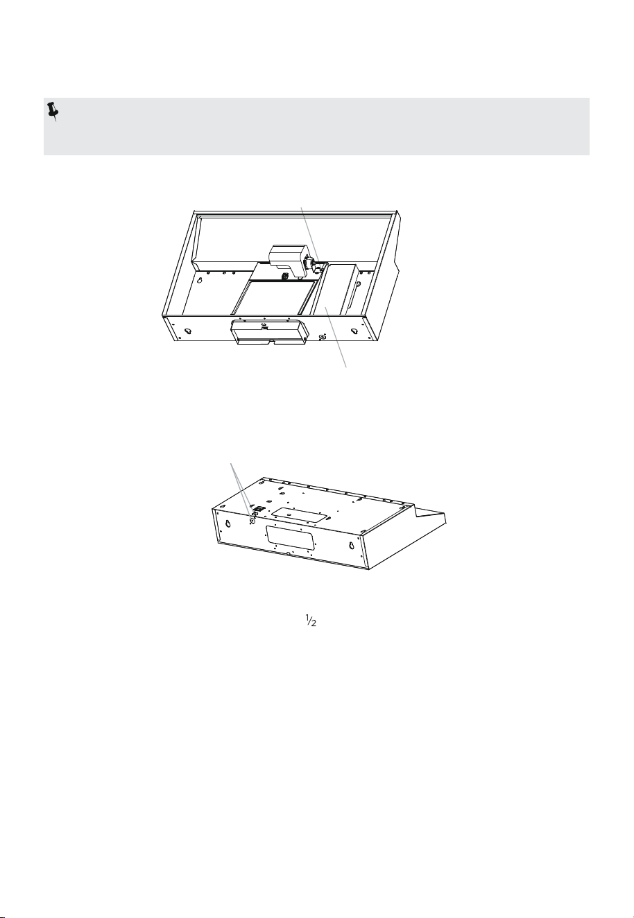
1.
2.
Remove the screws from the terminal box cover. Remove terminal bo x cover and
set aside.
3.
Remove the power supply knockout from the top or rear of the vent hood (depend-
ing on the incoming location of your home power supply cable) and install a UL
listed or CSA approved ” strain relief.
4.
5.
6.
7.
8.
Lift the hood into final position
Feed enough electrical wire through the ” UL listed or CSA approved strain relief to
make connections in the terminal box. Tighten the strain relief screws.
Position the range hood so that the large end of the keyhole slots are over the
mounting screws. Then push the hood toward the wall so that the screws are in the
neck of the slots. Tighten the mounting screws, making sure t he screws are in the
narrow neck of slots.
Add the 2 rear 0.49 * 5.0 cm rear mounting screws into the narrow neck of the rear
keyhole slots. These should screw into the horizontal support that was placed between
the two wall studs in Connect ventwork to hood.
Seal joints with vent clamps or duct tape to make secure and airtight.
Check that back draft dampers work properly.
Power Supply Cable Installation
For direct wire installations, run the home power supply cable according to the
National Electric Code or CSA standards and local codes and ordinances.
Do not reconnect power until the installation is complete.
Before starting the installation, remove the vent grill and grease filters.
Note
A
B
A
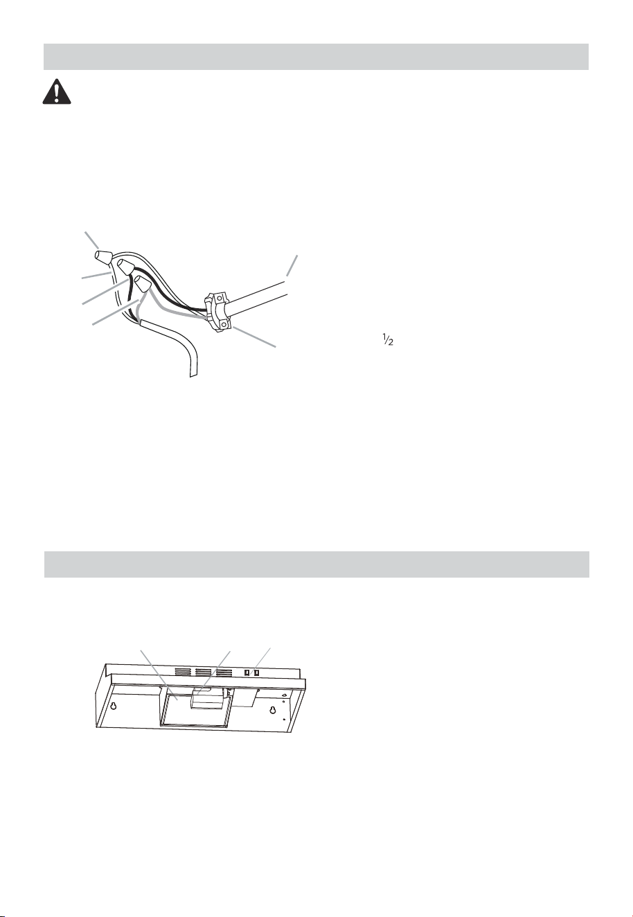
Make Electrical Connection
Electrical Shock Hazard
Disconnect power before servicing.
Replace all parts and panels before operating. Failure to do so can result in death or
electrical shock.
AB C
B
C
D
E
F
Warning
1.
Disconnect power.
2.
Use UL listed wire connectors and connect white wires (A) together.
3.
Use UL listed wire connectors and connect black wires (B) together.
A. White wires
B. Black wires
C. Green ground wire
D. UL listed wire connector
E. Home power supply cable
F. UL listed or CSA approved
” strain relief
The range hood is designed to remove smoke and cook-ing vapors from the cooktop
area. For best results, start the hood before cooking and allow it to operate several
minutes after the cooking is complete to clear all smoke f rom the kitchen.
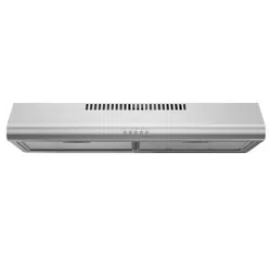
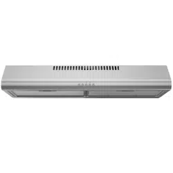
A. LED lights
B. Grease filter
C. Control knobs
19
A
OPERATION INSTRUCTIONS
Range Hood Use
CLEANING AND MAINTENANCE
Cleaning
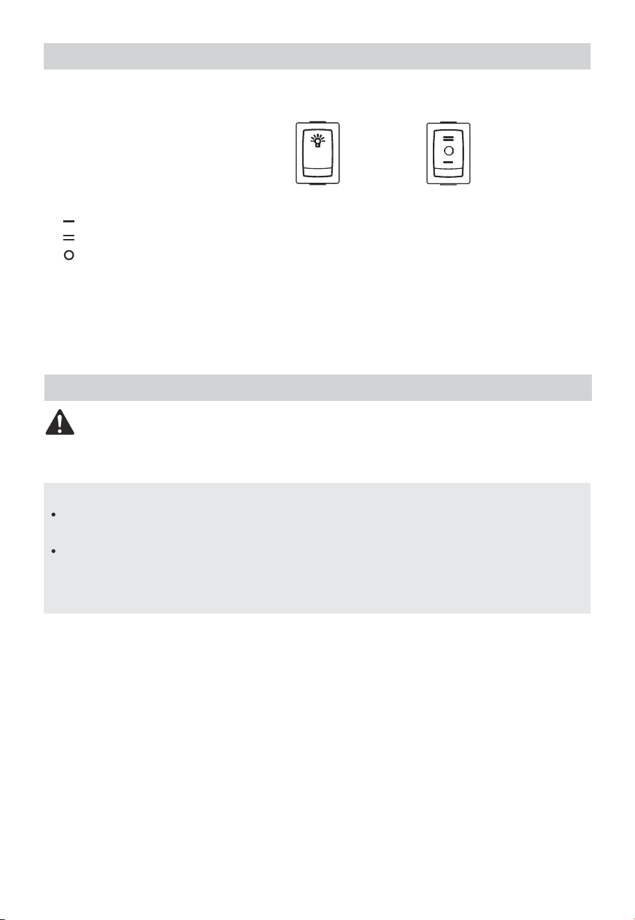
The hood controls are located at the bottom front section of the unit.
Motor Switch
Push lamp Switch
Push Motor Switch
:Motor Low Position
:Motor High Position
:Motor Off
Lamp Switch
To Reduce The Risk Of Fire Or Electrical shock disconnect from power supply before
cleaning.
Clean the stainless with warm soapy water using a clean sponge or cloth. Rinse with
clean water and dry with a soft clean cloth. DO NOT USE any cleaners like Stainless
Steel cleaners or any other types of cleaners containing any abrasive, c hlorides, c
hlorines or ammonia. It is recommended to use mild dish soap and water or a 50/50
solution of water and vinegar.
Warning
Clean the hood and grease filters frequently according to the following instruc-
tions. Replace grease filter before operating hood.
Important
Cleaning Method:
Exterior Surfaces
Do not use soap-filled scouring pads, abrasive cleaners, Cooktop Polishing
Creme, steel wool, gritty washcloths or paper towels.
To avoid damage to the stainless steel, do not use cleaners that contain chlorine.
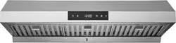
20
Range Hood Controls
Operating the Light
Operating the Fan
Assembly LED lights(Max 9W )
Electrical Shock Haxzard
Disconnect power before servicing.
Replace all parts and panels before operating. Failure to do so can result in death or
electrical shock.
Warning
Take down lamp-chimney,take down screw.
To clean or replace grease filter:
1.
Use E26 LED,Spin to tighten
1.
Place the lampshade in the hole
2.
According to " " direction loosen Plastic seat.
2.
To clean grease filter, soak the filters in hot water using a mild detergent. Rinse well
and shake to dry.
3.
Do not use ammonia. The aluminum on the grease filter will corrode and darken.
The grease filter is dishwasher safe.
To avoid grease filter damage while cleaning, place filter into the dishwasher top
rack for cleaning.
Note
21
22
TROUBLESHOOTING
Possible reason SolutionProblem
After installation,the
unit doesn’t work.
Light works,but
motor is not turning.
●
●
●
●
●
The power line and the cable
connector is not connected
properly.
The wires from the switches
are disconnected or loose.
Make sure the wires on the
switches are connected properly.
Check the power connections.
The motor is defective, possible
seized.
Change the motor.
The motor wire is not
connected.
Make sure the motor wire is
plugged into the terminal box
connector.
The unit is vibrating.
The motor is not secure in
place.
Tighten the motor in place.
●
The hood is not secured in
place.
Check the installation of the
hood.
●
Damaged blower wheel. Change the blower.
●
●
●
●
●
The motor is working,
but the lights are not.
Change the lamp.
Make sure the lamp is seated
properly.
Defective lamp.
●
Make sure the wires on light
switch are connected properly.
The wires on the light switch are
loose.
●
Adjust the duct opening
direction.
The direction of duct opening is
against the wind.
The lamp is loose.
●
heck installation instructions. The hood might be hanging to
high from the cook top.
●
Change the ducting to correct
size.
Using the wrong size of ducting.
The hood is not
venting out
properly.
The wind from the opened
windows or opened doors in the
surrounding area are affecting
the ventilation of the hood.
Close all the windows and
doors to eliminate the outside
wind flo.
Blockage in the duct
opening or duct work.
Remove all the blocking from
the duct work or duct
opening.
Vent grill or grease
filter is vibrating.
ent grill or grease filter is loose. ake sure vent grill or grease
filter is installed correctly.
logo, word marks, trade name, trade dress and all versions thereof are
trademarks, copyrights and other intellectual property rights, and all goodwill derived
from using any part of an Midea trademark. Use of Midea trademark for commercial
purposes without the prior written consent of Midea may constitute trademark
infringement or unfair competition in violation of relevant laws.
This manual is created by Midea and Midea reserves all copyrights thereof. No entity or
individual may use, duplicate, modify, distribute in whole or in part this manual, or
bundle or sell with other products without the prior written consent of Midea.
All the described functions and instructions were up to date at the time of printing this
manual. However, the actual product may vary due to improved functions and designs.
TRADEMARKS, COPYRIGHTS
AND LEGAL STATEMENT
DISPOSAL AND RECYCLING
Important instructions for environment
Compliance with the WEEE Directive and Disposing of the Waster Product:
This product complies with EU WEEE Directive (2012/19/EU). This product bears a
classification symbol for waster electrical and electronic equipment (WEEE).
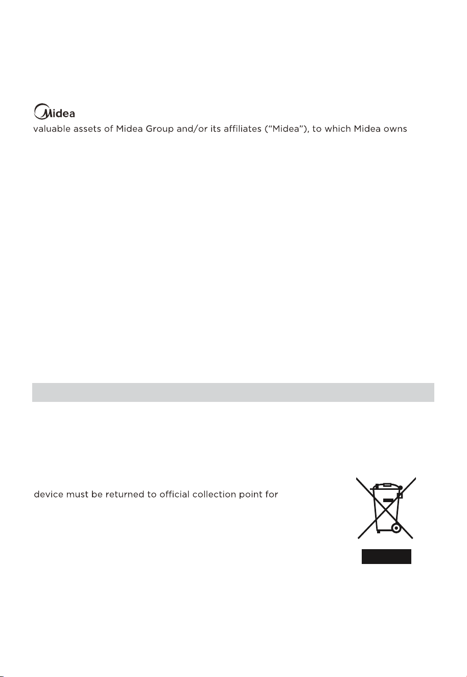
This symbol indicates that this product shall not be disposed
with other household wastes at the end of its service life. Used
recycling of electrical electronic devices. To find these
collection systems please contact to your local authorities or
retailer where the product was purchased. Each household
performs important role in recovering and recycling of old
appliance. Appropriate disposal of used appliance helps
prevent potential negative consequences for the environment
and human health.
23
Compliance with RoHS Directive
The product you have purchased complies with EU RoHS Directive (2011/65/EU). It does
not contain harmful and prohibited materials specified in the Directive.
Package information
Packaging materials of the product are manufactured from
recyclable materials in accordance with our National Environ-
ment Regulations. Do not dispose of the packaging materials
together with the domestic or other wastes. Take them to the
packaging material collection points designated by the local
authorities.
DATA PROTECTION NOTICE
For the provision of the services agreed with the customer,
we agree to comply without restriction with all stipulations of applicable data protection
law, in line with agreed countries within which services to the customer will be delivered,
as well as, where applicable, the EU General Data Protection Regulation (GDPR).
Generally, our data processing is to fulfil our obligation under contract with you and for
product safety reasons, to safeguard your rights in connection with warranty and
product registration questions. In some cases, but only if appropriate data protection is
ensured, personal data might be transferred to recipients located outside of the
European Economic Area.
Further information are provided on request. You can contact our Data Protection
[email protected]. To exercise your rights such as right to object your
personal date being processed for direct marketing purposes, please contact us via
[email protected]. To find further information, please follow the QR Code.
24


16173000A22733
V1.0