

Legal Informaon
©2023 Hangzhou Hikvision Digital Technology Co., Ltd. All rights reserved.
About this Manual
The Manual includes instrucons for using and managing the Product. Pictures, charts, images and
all other informaon hereinaer are for descripon and explanaon only. The informaon
contained in the Manual is subject to change, without noce, due to rmware updates or other
reasons. Please nd the latest version of this Manual at the Hikvision website ( hps://
www.hikvision.com/ ).
Please use this Manual with the guidance and assistance of professionals trained in
supporng the
Product.
Trademarks
and other Hikvision's trademarks and logos are the properes of
Hikvision in various jurisdicons.
Other trademarks and logos menoned are the properes of their respecve owners.
Disclaimer
TO THE MAXIMUM EXTENT PERMITTED BY APPLICABLE LAW, THIS MANUAL AND THE PRODUCT
DESCRIBED, WITH ITS HARDWARE, SOFTWARE AND FIRMWARE, ARE PROVIDED "AS IS" AND "WITH
ALL FAULTS AND ERRORS". HIKVISION MAKES NO WARRANTIES, EXPRESS OR IMPLIED, INCLUDING
WITHOUT LIMITATION, MERCHANTABILITY, SATISFACTORY QUALITY, OR FITNESS FOR A PARTICULAR
PURPOSE. THE USE OF THE PRODUCT BY YOU IS AT YOUR OWN RISK. IN NO EVENT WILL HIKVISION
BE LIABLE TO YOU FOR ANY SPECIAL, CONSEQUENTIAL, INCIDENTAL, OR INDIRECT DAMAGES,
INCLUDING, AMONG OTHERS, DAMAGES FOR LOSS OF BUSINESS PROFITS, BUSINESS
INTERRUPTION, OR LOSS OF DATA, CORRUPTION OF SYSTEMS, OR LOSS OF DOCUMENTATION,
WHETHER BASED ON BREACH OF CONTRACT, TORT (INCLUDING NEGLIGENCE), PRODUCT LIABILITY,
OR OTHERWISE, IN CONNECTION WITH THE USE OF THE PRODUCT, EVEN IF HIKVISION HAS BEEN
ADVISED OF THE POSSIBILITY OF SUCH DAMAGES OR LOSS.
YOU ACKNOWLEDGE THAT THE NATURE OF THE INTERNET PROVIDES FOR INHERENT SECURITY
RISKS, AND HIKVISION SHALL NOT TAKE ANY RESPONSIBILITIES FOR ABNORMAL OPERATION,
PRIVACY LEAKAGE OR OTHER DAMAGES RESULTING FROM CYBER-ATTACK, HACKER ATTACK, VIRUS
INFECTION, OR OTHER INTERNET SECURITY RISKS; HOWEVER, HIKVISION WILL PROVIDE TIMELY
TECHNICAL SUPPORT IF REQUIRED.
YOU AGREE TO USE THIS PRODUCT IN COMPLIANCE WITH ALL APPLICABLE LAWS, AND YOU ARE
SOLELY RESPONSIBLE FOR ENSURING THAT YOUR USE CONFORMS TO THE APPLICABLE LAW.
ESPECIALLY, YOU ARE RESPONSIBLE, FOR USING THIS PRODUCT IN A MANNER THAT DOES NOT
INFRINGE ON THE RIGHTS OF THIRD PARTIES, INCLUDING WITHOUT LIMITATION, RIGHTS OF
PUBLICITY, INTELLECTUAL PROPERTY RIGHTS, OR DATA PROTECTION AND OTHER PRIVACY RIGHTS.
YOU SHALL NOT USE THIS PRODUCT FOR ANY PROHIBITED END-USES, INCLUDING THE
Network Indoor Staon User Manual
i

DEVELOPMENT OR PRODUCTION OF WEAPONS OF MASS DESTRUCTION, THE DEVELOPMENT OR
PRODUCTION OF CHEMICAL OR BIOLOGICAL WEAPONS, ANY ACTIVITIES IN THE CONTEXT RELATED
TO ANY NUCLEAR EXPLOSIVE OR UNSAFE NUCLEAR FUEL-CYCLE, OR IN SUPPORT OF HUMAN
RIGHTS ABUSES.
IN THE EVENT OF ANY CONFLICTS BETWEEN THIS MANUAL AND THE APPLICABLE LAW, THE LATTER
PREVAILS.
Data Protecon
During the use of device, personal data will be collected, stored and processed. To protect data,
the development of Hikvision devices incorporates privacy by design principles. For example, for
device with facial recognion features, biometrics data is stored in your device with encrypon
method; for ngerprint device, only ngerprint template will be saved, which is impossible to
reconstruct a ngerprint image.
As data controller, you are advised to collect, store, process and transfer data in accordance with
the applicable data
protecon laws and regulaons, including without limitaon, conducng
security controls to safeguard personal data, such as, implemenng reasonable administrave and
physical security controls, conduct periodic reviews and assessments of the
eecveness of your
security controls.
Network Indoor Staon User Manual
ii
Symbol Convenons
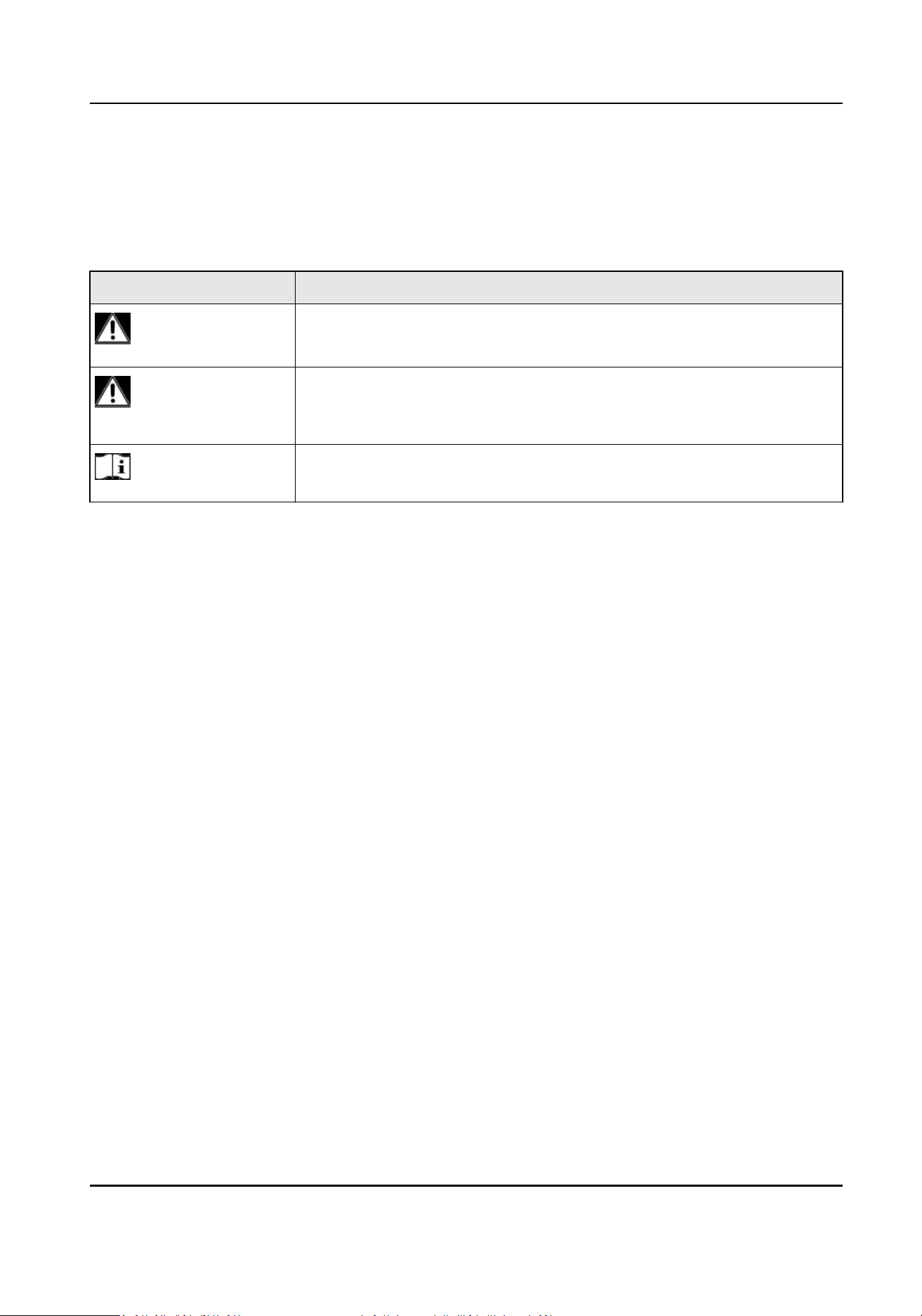
The symbols that may be found in this document are dened as follows.
Symbol Descripon
Danger
Indicates a hazardous situaon which, if not avoided, will or could
result in death or serious injury.
Cauon
Indicates a potenally hazardous situaon which, if not avoided, could
result in equipment damage, data loss, performance degradaon, or
unexpected results.
Note
Provides addional informaon to emphasize or supplement
important points of the main text.
Network Indoor Staon User Manual
iii

Regulatory Informaon
EU Conformity Statement
This product and - if applicable - the supplied accessories too are marked with "CE"
and comply therefore with the applicable harmonized European standards listed
under the EMC Direcve 2014/30/EU, RE Direcve 2014/53/EU,the RoHS Direcve
2011/65/EU
2012/19/EU (WEEE direcve): Products marked with this symbol cannot be disposed
of as unsorted municipal waste in the European Union. For proper recycling, return
this product to your local supplier upon the purchase of equivalent new equipment,
or dispose of it at designated
collecon points. For more informaon see:
www.recyclethis.info
2006/66/EC (baery direcve): This product contains a baery that cannot be
disposed of as unsorted municipal waste in the European Union. See the product
documentaon for specic baery informaon. The baery is marked with this
symbol, which may include
leering to indicate cadmium (Cd), lead (Pb), or mercury
(Hg). For proper recycling, return the
baery to your supplier or to a designated
collecon point. For more informaon see:www.recyclethis.info
Industry Canada ICES-003 Compliance
This device meets the CAN ICES-3 (B)/NMB-3(B) standards requirements.
This device complies with Industry Canada licence-exempt RSS standard(s). Operaon is subject to
the following two
condions:
1. this device may not cause interference, and
2. this device must accept any interference, including interference that may cause undesired
operaon of the device.
Le présent appareil est conforme aux CNR d'Industrie Canada applicables aux appareils
radioexempts de licence.
L'exploitaon est autorisée aux deux condions suivantes :
1. l'appareil ne doit pas produire de brouillage, et
2.
l'ulisateur de l'appareil doit accepter tout brouillage radioélectrique subi, même si le brouillage
est suscepble d'en compromere le fonconnement.
Under Industry Canada regulaons, this radio transmier may only operate using an antenna of a
type and maximum (or lesser) gain approved for the transmier by Industry Canada. To reduce
potenal radio interference to other users, the antenna type and its gain should be so chosen that
the equivalent isotropically radiated power (e.i.r.p.) is not more than that necessary for successful
communicaon.
Network Indoor Staon User Manual
iv

Conformément à la réglementaon d'Industrie Canada, le présent émeeur radio peut fonconner
avec une antenne d'un type et d'un gain maximal (ou inférieur) approuvé pour l'émeeur par
Industrie Canada. Dans le but de réduire les risques de brouillage radioélectrique à l'intenon des
autres
ulisateurs, il faut choisir le type d'antenne et son gain de sorte que la puissance isotrope
rayonnée équivalente (p.i.r.e.) ne dépasse pas l'intensité nécessaire à l'établissement d'une
communicaon sasfaisante.
This equipment should be installed and operated with a minimum distance 20cm between the
radiator and your body.
Cet équipement doit être installé et
ulisé à une distance minimale de 20 cm entre le radiateur et
votre corps.
If a power adapter is provided in the device package, use the provided adapter only. If no power
adapter is provided, ensure the power adapter or other power supply complies with Limited Power
Source. Refer to the product label for the power supply output parameters.
Network Indoor Staon User Manual
v
About this Manual
Get the manual and related soware from or the ocial website (hp://www.hikvision.com).
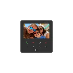
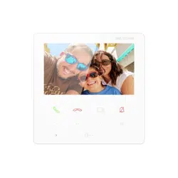
Product Model
Network Indoor Staon DS-KH6110-WE1
Network Indoor Staon User Manual
vi

Contents
Chapter 1 Introducon of Touch Buons .................................................................................... 1
Chapter 2 Acvaon ................................................................................................................... 3
2.1 Acvate Indoor Staon .......................................................................................................... 3
2.2 Acvate via iVMS-4200 Client Soware ................................................................................. 4
Chapter 3 Local Conguraon ..................................................................................................... 6
3.1 Quick Operaon ..................................................................................................................... 6
3.2 Basic Sengs ....................................................................................................................... 14
3.2.1 Set Indoor Staon Network Parameters ..................................................................... 14
3.2.2 Connect to Wi-Fi ......................................................................................................... 15
3.2.3 Set Linked Device IP .................................................................................................... 16
3.2.4 Set Local
Informaon .................................................................................................. 18
3.2.5 SIP
Sengs .................................................................................................................. 19
3.2.6 Add Camera ................................................................................................................ 21
3.3 Password Sengs ................................................................................................................ 22
3.3.1 Security
Sengs .......................................................................................................... 22
3.3.2 Modify Unlock/Duress Code ....................................................................................... 22
3.4 Device Informaon .............................................................................................................. 22
3.5 General
Sengs ................................................................................................................... 23
3.6 Preference ............................................................................................................................ 25
3.7 System Sengs .................................................................................................................... 26
3.8 Synchronize Time ................................................................................................................. 28
3.9 Sound
Sengs ..................................................................................................................... 29
3.9.1 Call Sengs ................................................................................................................. 29
3.9.2 Volume
Sengs .......................................................................................................... 31
3.10 Via the mobile client .......................................................................................................... 31
3.10.1 Link to the Mobile Client ........................................................................................... 31
Network Indoor Staon User Manual
vii

3.10.2 Unlink the Account ................................................................................................... 32
Chapter 4 Local Operaon ........................................................................................................ 34
4.1 Call
Sengs .......................................................................................................................... 34
4.1.1 Add Contact ................................................................................................................ 34
4.1.2 Call Resident ............................................................................................................... 35
4.1.3 Call Indoor Extension/Indoor Staon .......................................................................... 35
4.1.4 Receive Call ................................................................................................................. 36
4.1.5 View Call Logs ............................................................................................................. 36
4.2 Leave Message ..................................................................................................................... 37
4.3 Live View .............................................................................................................................. 37
4.4 Call Elevator ......................................................................................................................... 38
4.5 Informaon Management .................................................................................................... 39
Chapter 5 Client
Soware Conguraon ................................................................................... 40
5.1 Device Management ............................................................................................................ 40
5.1.1 Add Video Intercom Devices ....................................................................................... 40
5.1.2 Modify Network
Informaon ...................................................................................... 42
5.2 System
Conguraon ........................................................................................................... 43
5.3 Remote Conguraon .......................................................................................................... 43
5.3.1 System ......................................................................................................................... 43
5.3.2 Video Intercom ........................................................................................................... 48
5.3.3 Network ...................................................................................................................... 54
5.4 Call Indoor
Staon via Client Soware ................................................................................ 57
5.5 Receive Call from Indoor
Staon/Door Staon .................................................................... 58
5.6 View Live Video of Door Staon and Outer Door Staon .................................................... 59
5.7 View Call Logs ...................................................................................................................... 59
5.8 Release
Noce ..................................................................................................................... 60
5.9 Search Video Intercom Informaon ..................................................................................... 63
5.9.1 Search Call Logs ........................................................................................................... 63
Network Indoor Staon User Manual
viii

Chapter 1 Introducon of Touch Buons
You can operate the device locally via touch buons.
You can answer or hang up the call on the calling page, unlock the door and view the live videos of
the door staon on the live view page and mute the device via touch buons. When you are not
on the page of call or live view, you can use touch buons to enter dierent pages.
Note
You can also customize the four customizable buons remotely via iVMS-4200 Client Soware.
Figure 1-1 Touch Buons Funcon 1
Note
You need to long press the buon Live View and Mute and realize relave funcons.
Network Indoor Staon User Manual
1

Figure 1-2 Touch Buons Funcon 2
Network Indoor Staon User Manual
2
Chapter 2 Acvaon
2.1 Acvate Indoor Staon
You can congure and operate the indoor staon aer creang a password for the device
acvaon.
Steps
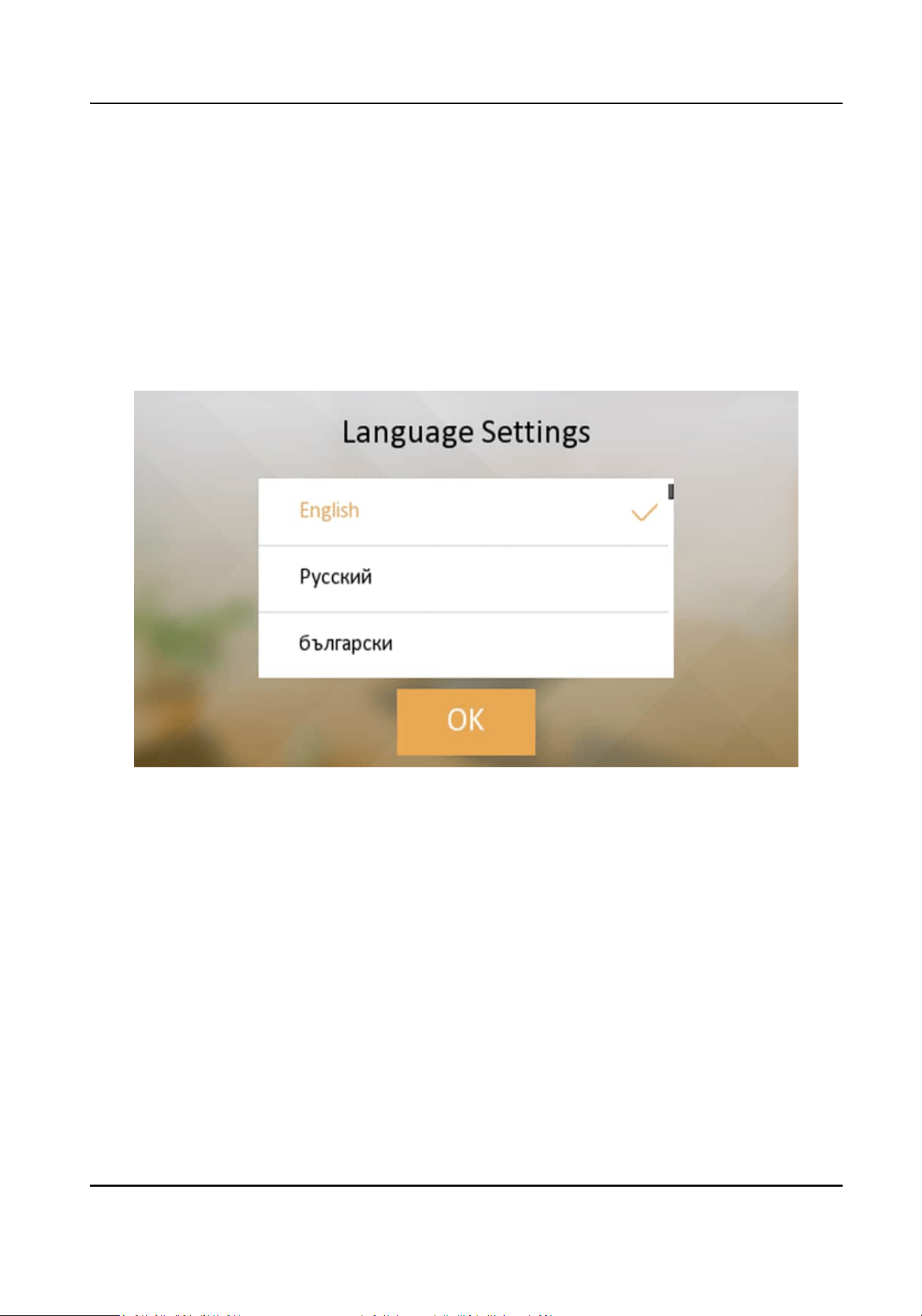
1.
Power on the device. It will enter the page of language sengs.
Figure 2-1 Language Sengs
2.
Aer seng the language, it will enter the acvaon page.
Network Indoor Staon User Manual
3
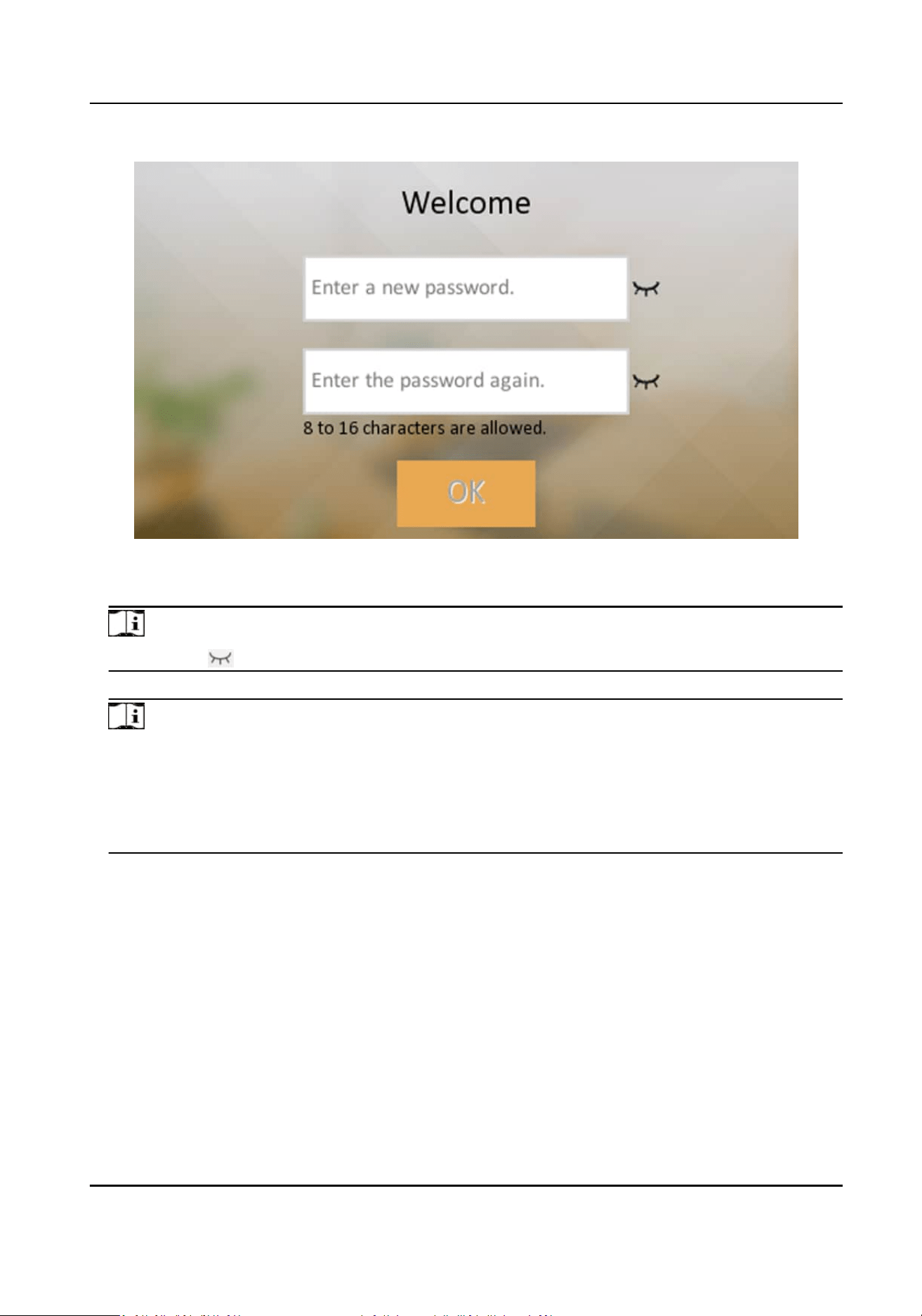
Figure 2-2 Acvaon Page
3.
Create a password and conrm it.
Note
You can click to enable or disable password reveal.
4.
Tap OK to acvate the indoor staon.
Note
We highly recommend you to create a strong password of your own choosing (using a minimum
of 8 characters, including at least three kinds of following categories: upper case leers, lower
case leers, numbers, and special characters) in order to increase the security of your product.
And we recommend you change your password regularly, especially in the high security system,
changing the password monthly or weekly can beer protect your product.
Aer
device acvaon, the wizard page will pop up.
2.2
Acvate via iVMS-4200 Client Soware
You can only congure and operate the indoor staon aer creang a password for the device
acvaon.
Before You Start
Default parameters of indoor staon are as follows:
Network Indoor Staon User Manual
4
●
Default IP Address: 192.0.0.64.
●
Default Port No.: 8000.
●
Default User Name: admin.
Steps
1.
Run the client
soware, enter Device Management, check the Online Device area.
2.
Select an inacvated device and click the Acvate.
3.
Create a password, and
conrm the password.
Note
We highly recommend you to create a strong password of your own choosing (using a minimum
of 8 characters, including at least three kinds of following categories: upper case leers, lower
case leers, numbers, and special characters) in order to increase the security of your product.
And we recommend you change your password regularly, especially in the high security system,
changing the password monthly or weekly can beer protect your product.
4.
Click OK to acvate the device.
Network Indoor Staon User Manual
5
Chapter 3 Local Conguraon
3.1 Quick Operaon
Aer device acvaon, the wizard page will pop up. If you acvate you device via Client Soware,
there will not be wizard for quick operaon.
Steps
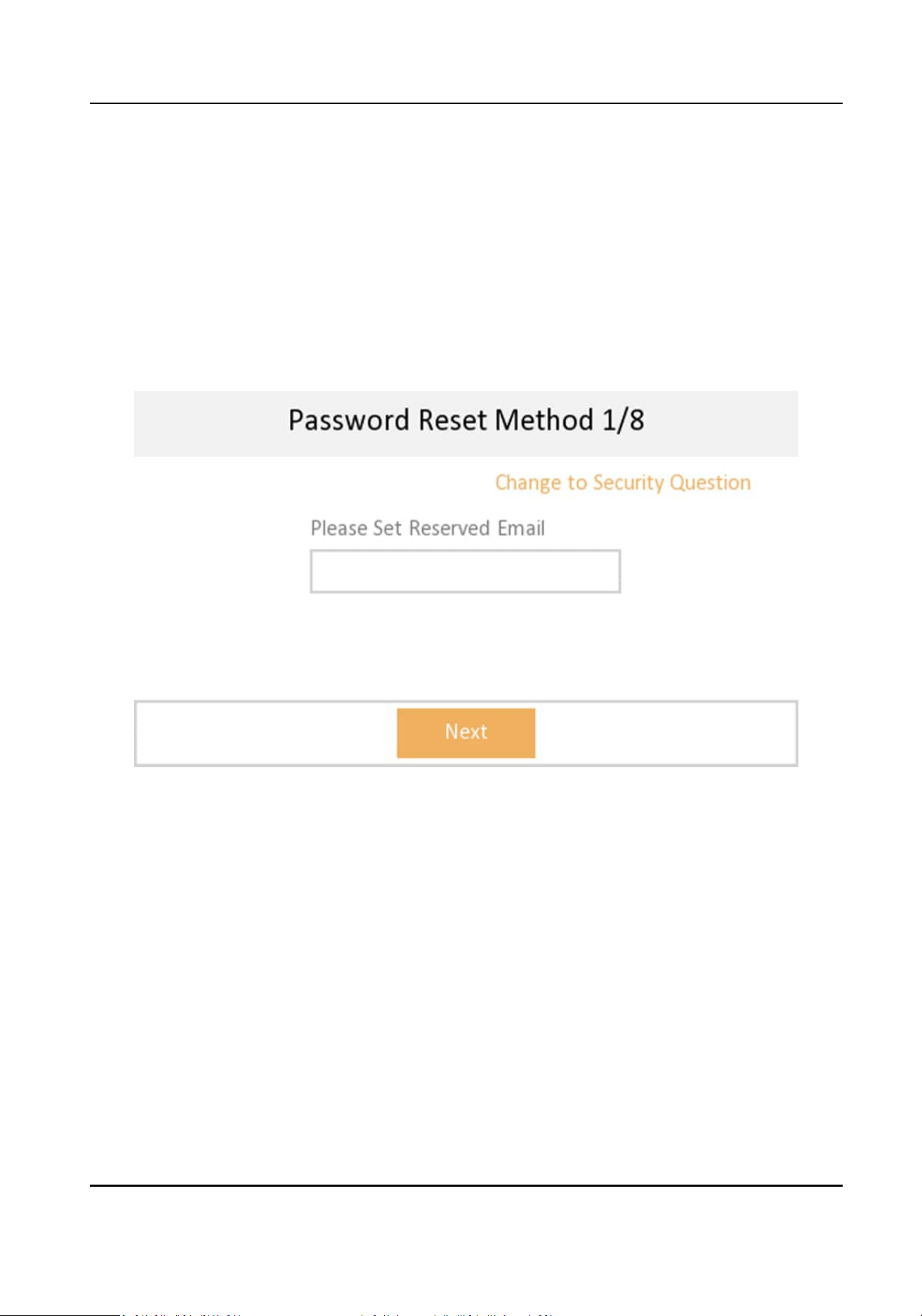
1.
Set password reset methods and tap Next.
Figure 3-1 Set reserved E-mail
Network Indoor Staon User Manual
6
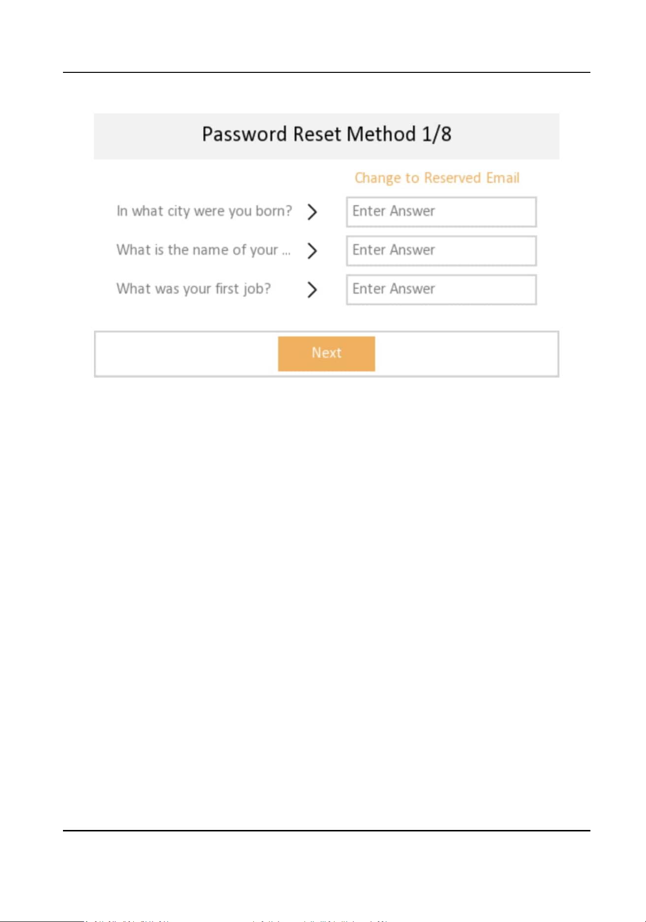
Figure 3-2 Set Security Quesons
-
Bind an email address. If you forget your admin and acvaon password, you can change the
password via the reserved email address.
-
Tap Change to Security Queson to select security quesons and enter the answers. If you
forget your admin and acvaon password, you can change the password via answering the
quesons.
2.
Set network parameters and tap Next.
Network Indoor Staon User Manual
7
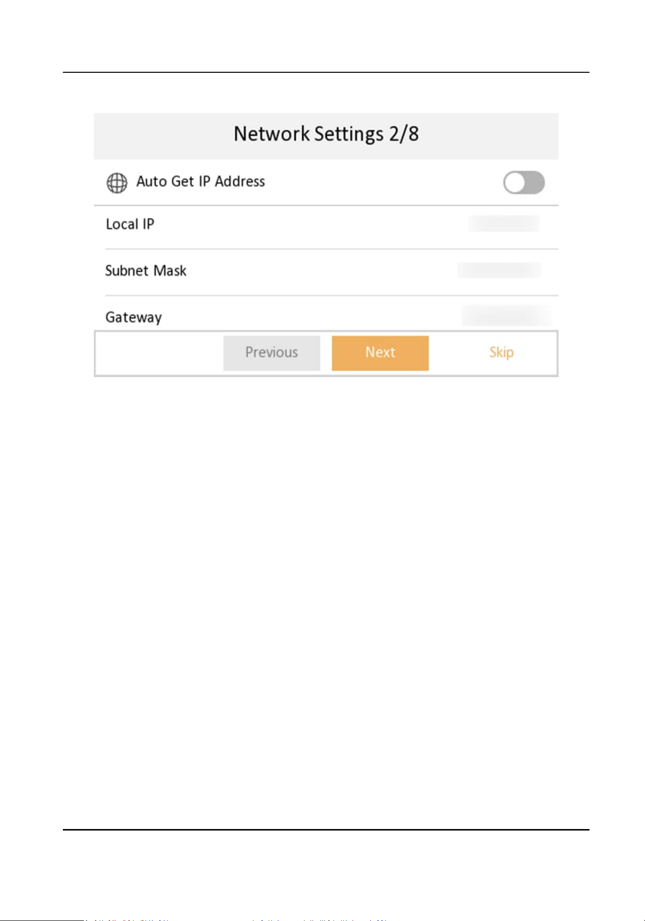
Figure 3-3 Network Sengs
-
Edit Local IP, Subnet Mask and Gateway parameters manually.
-
Enable Auto Get IP address, the device will get network parameters
automacally.
3.
Congure the indoor staon.
Network Indoor Staon User Manual
8
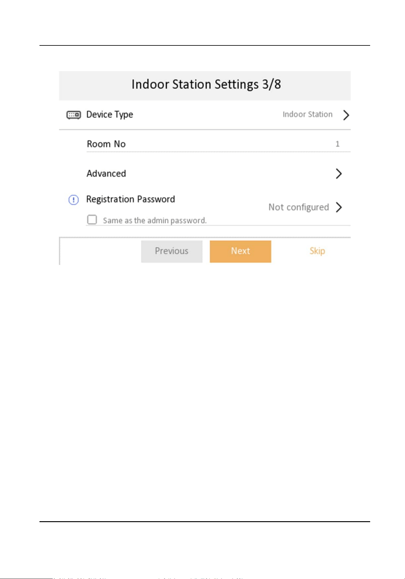
Figure 3-4 Indoor Staon Sengs
1) Select Device Type as Indoor Staon or Indoor Extension.
2) Set Room No..
3)
Congure advanced sengs. Set Community No., Building No., Unit No. and Floor No.
4) Set
Registraon Password.
5) Tap Next.
4.
Enable the Wi-Fi
funcon. Select a Wi-Fi from the list and enter the Wi-Fi's password to get
connected. Tap Next.
Network Indoor Staon User Manual
9
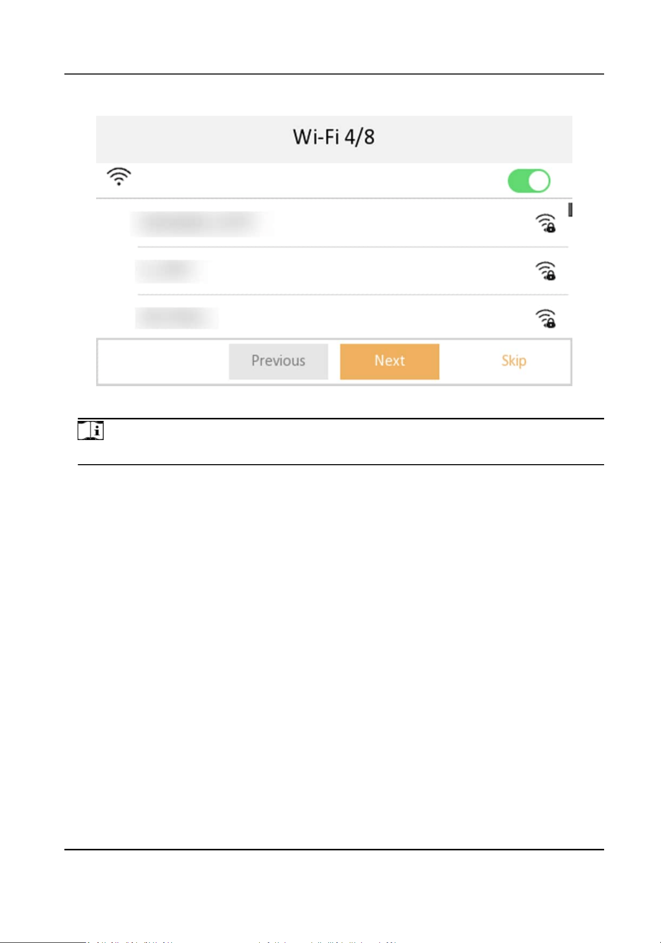
Figure 3-5 Wi-Fi Sengs
Note
The device should support Wi-Fi.
5.
Set me and tap Next.
Network Indoor Staon User Manual
10
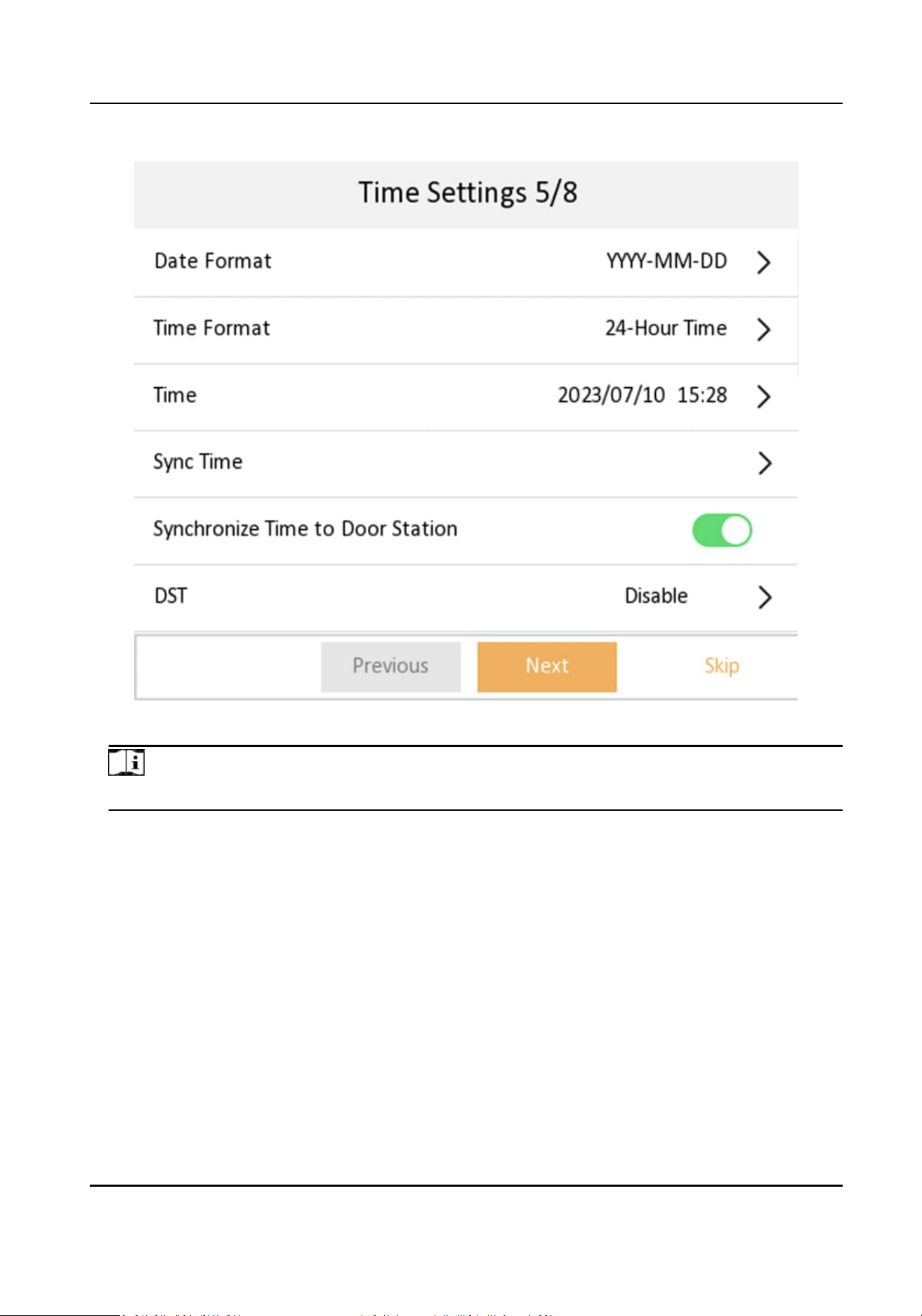
Figure 3-6 Time Sengs
Note
The me can be synchronized to door staons.
1) Tap Date Format and Time Format to set the me format.
2) Tap Time to set me manually.
3) Tap Sync Time to select Time Zone and enable NTP
funcon.
4) Tap to enable Synchronize Time to Door Staon to synchronize indoor staon me to linked
door
staon.
5) Enable DST.Set the DST start me, end me and bias me.
6.
Congure the Hik-Connect service sengs.
Network Indoor Staon User Manual
11
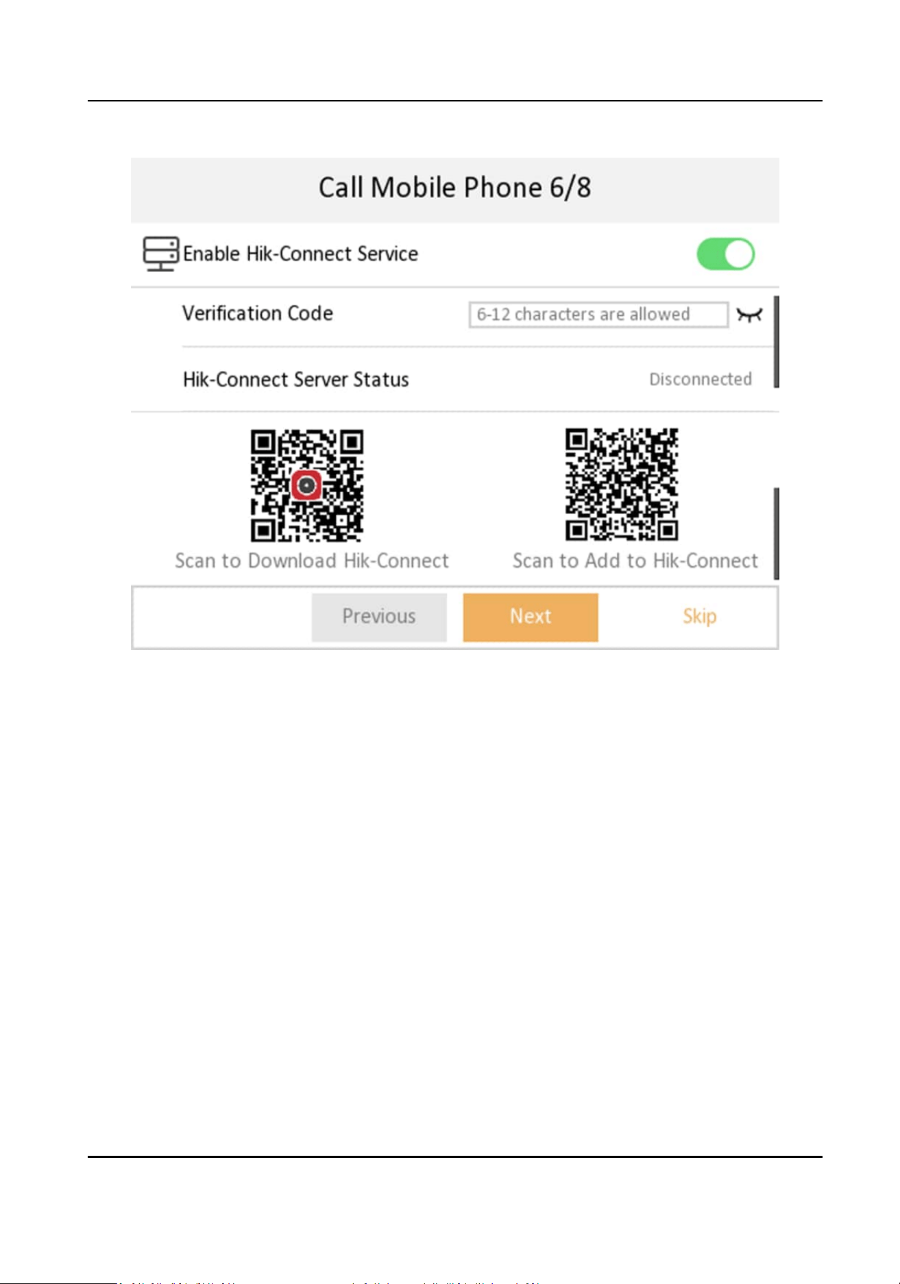
Figure 3-7 Call Mobile Phone
1) Enable Hik-Connect service.
2) Edit vericaon code or use the acvaon password by default.
3) View Hik-Connect Server Status.
4) Scan the
rst QR Code to download the APP of Hik-Connect. Scan the second QR Code to add
your device to the APP.
Aer adding the device to the APP, you can congure the device
remotely.
5) Tap Next.
7.
Link related devices and tap Next. If the device and the indoor
staon are in the same LAN, the
device will be displayed in the list.
1) Tap the door
staon in the list to link.
Network Indoor Staon User Manual
12
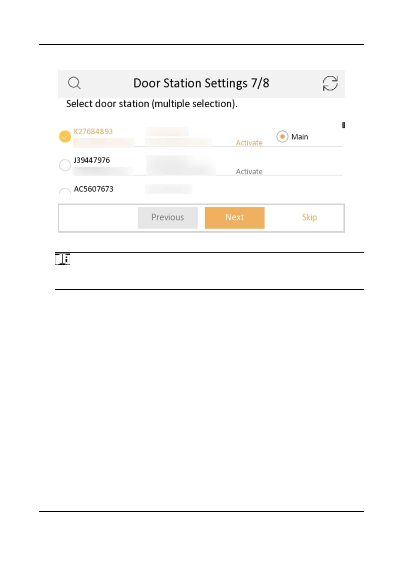
Figure 3-8 Door Staon Sengs
Note
If the door staon is inacve, the system will acvate the door staon automacally and
assign the network parameters to the door staon.
2) Tap Next.
8.
Oponal: Enable Indoor Extension and link related indoor extension devices. Tap Finish. If the
indoor extension and the indoor
staon are in the same LAN, the device will be displayed in the
list. Tap the device or enter the serial No. to link.
Network Indoor Staon User Manual
13
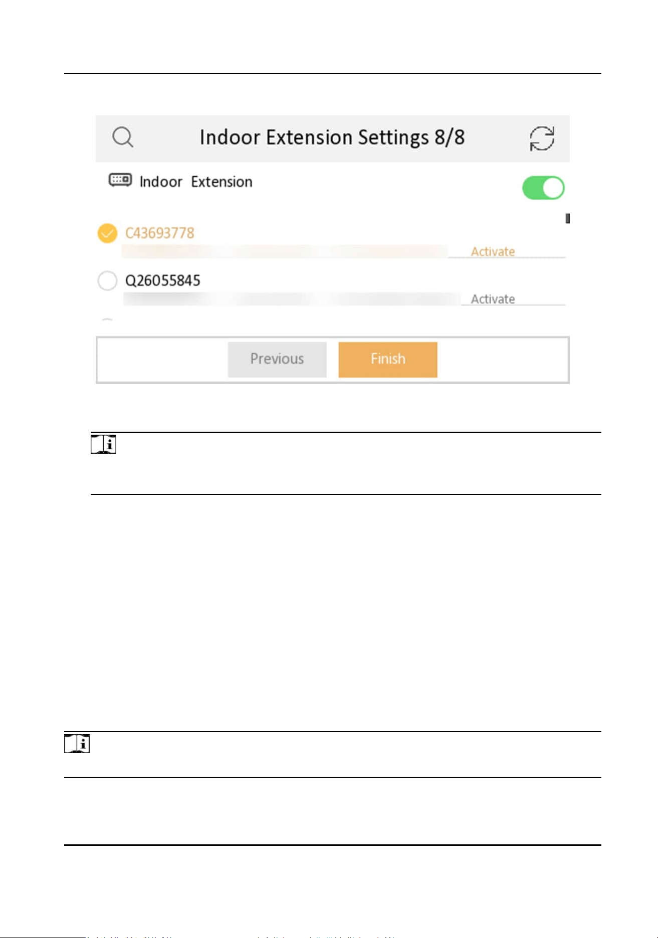
Figure 3-9 Indoor Extension Sengs
1) Tap the indoor extension in the list to link.
Note
If the indoor extension is inacve, the system will acvate the indoor staon automacally
and assign the network parameters to the indoor staon.
9.
Tap Finish to save the sengs.
3.2 Basic
Sengs
Basic sengs is required before starng using the indoor staon. It is necessary to set the indoor
staon network, room No., linked devices, device me display, and so on.
3.2.1 Set Indoor
Staon Network Parameters
Network connecon is mandatory for the use of the indoor staon. Set the network parameters
aer acvang the indoor staon. Only when the IP address of the indoor staon is in the same
network segment as other devices, it can work properly in the same system.
Steps
Note
The default IP address of the indoor staon is 192.0.0.64.
Network Indoor Staon User Manual
14
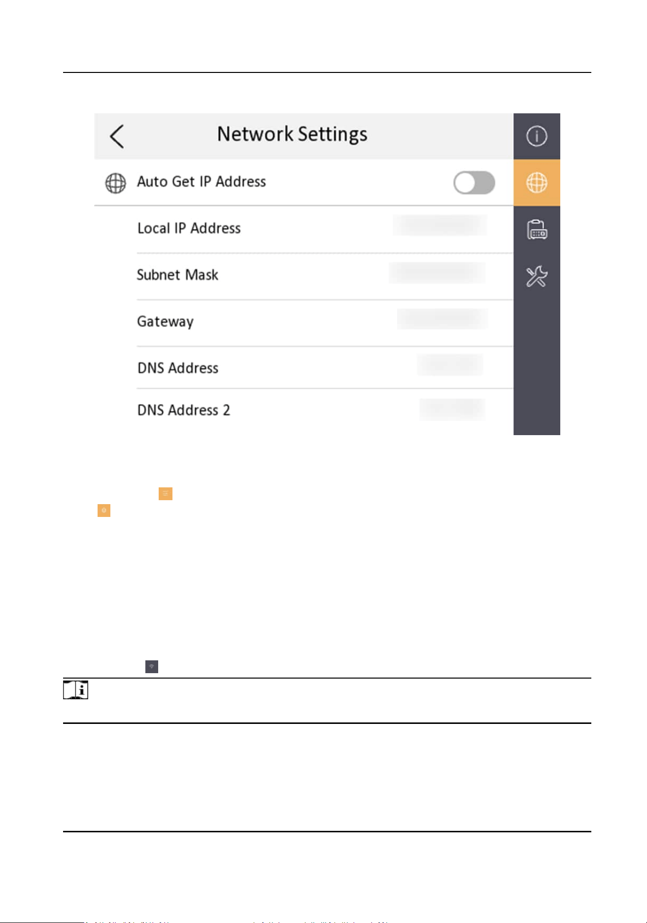
Figure 3-10 Network Informaon
Two ways are available for you to set IP address: DHCP, and set IP address manually.
1.
Tap
Sengs → → Conguraon , and enter admin (acvaon) password.
2.
Tap to enter the network sengs page.
3.
Set the network parameters.
-
Enable DHCP, and the system can assign an IP address of the indoor staon automacally.
-
Disable the DHCP funcon, and set the IP address manually. You should set the device IP
address, the gateway, the DNS address.
3.2.2 Connect to Wi-Fi
Set Wi-Fi connecon.
Tap Sengs → . Enable Wi-Fi, and the indoor staon will search available Wi-Fi automacally.
Note
The Wi-Fi IP can be changed.
Network Indoor Staon User Manual
15
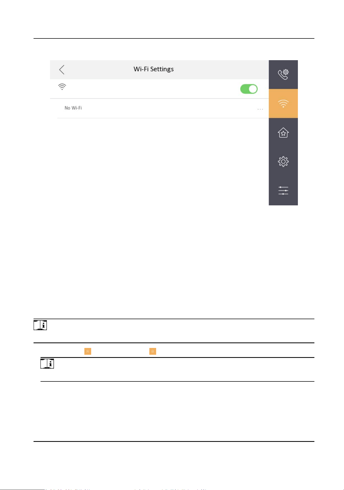
Figure 3-11 Wi-Fi Sengs
Select an Wi-Fi and connect.
3.2.3 Set Linked Device IP
Linked network parameters refers to network parameters of devices (such as door staon,
doorphone, main staon, center, etc.), to which the indoor staon is linked. Linked devices for
indoor
staon refer to door staon, center, main staon, and doorphone.
With the private SIP protocol, intercom can be realized only when all these devices are in the same
network segment with the indoor
staon.
Steps
Note
Here takes main door staon network sengs as an example.
1.
Tap Sengs → → Conguraon → to enter the device management page.
Note
Default admin password is the acvaon password.
2.
Tap Main Door Staon to pop up the device informaon dialog.
Network Indoor Staon User Manual
16
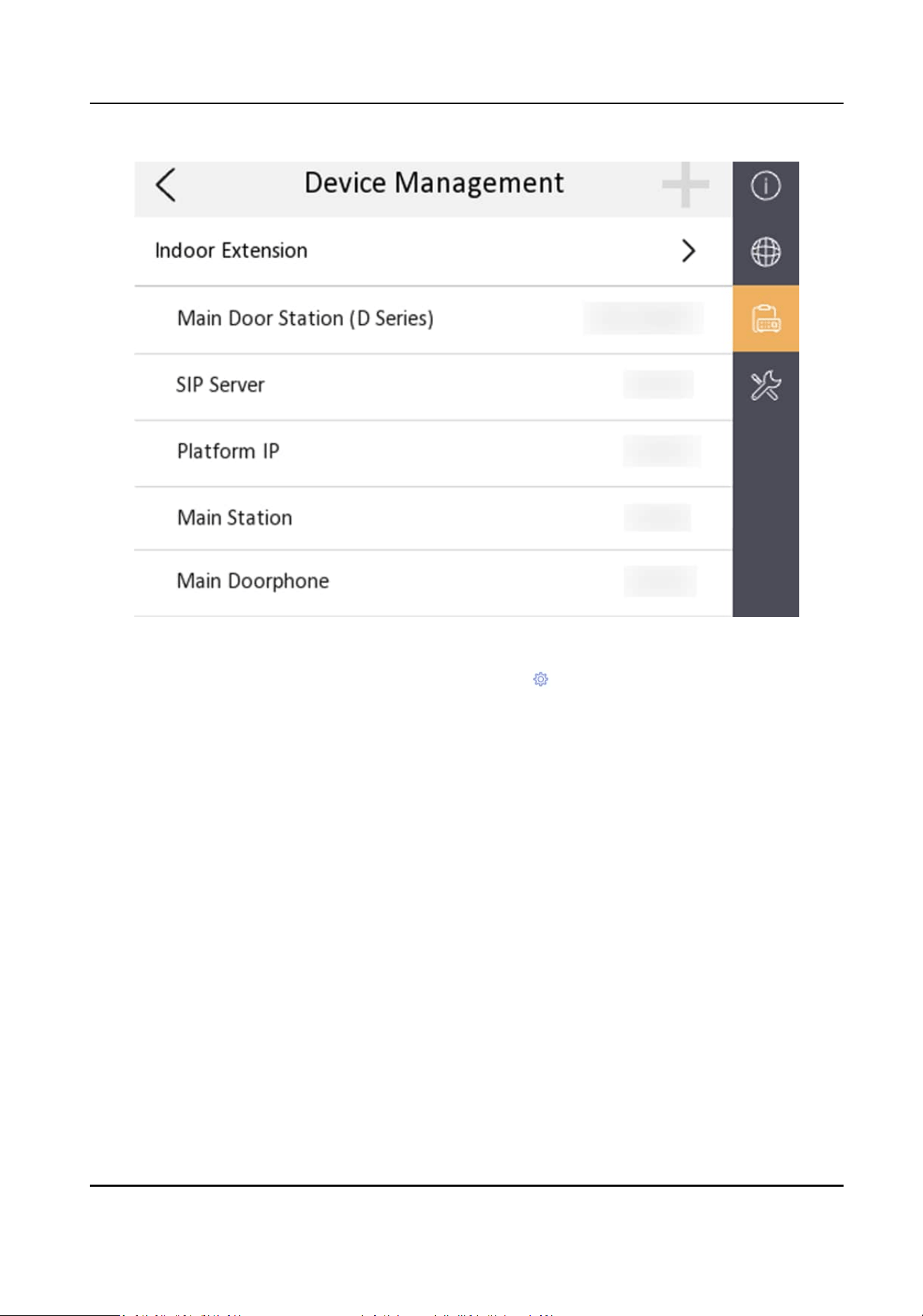
Figure 3-12 Device Management
Set the parameters of the linked door
staon. Tap to set parameters of the door staon.
3.
Select a device to link. Edit following parameters.
Name
You can edit the name of the device.
Language
Select a language from the drop-down list for the device.
Network
Enable Auto Get IP Address and the system will assign network parameters
automacally, or
you can edit network parameters manually.
Door Lock Parameters
Aer wire the lock with the door staon, you can set name and door opening duraon
according to your needs.
Volume Sengs
Set microphone volume and output volume.
Call Number Sengs
The call No. should be the same as the indoor staon's room No. If press the call buon of
the door
staon, you can call the indoor staon directly.
Network Indoor Staon User Manual
17
Restore to Default Sengs
Restore Default Sengs
Tap Restore Default Sengs to restore parameters except network parameters and
acvaon password to factory sengs. And the system will reboot automacally.
Restore All
All parameters will be restored to the factory sengs. The system will reboot to take
eect.
Device Reboot
Reboot the device.
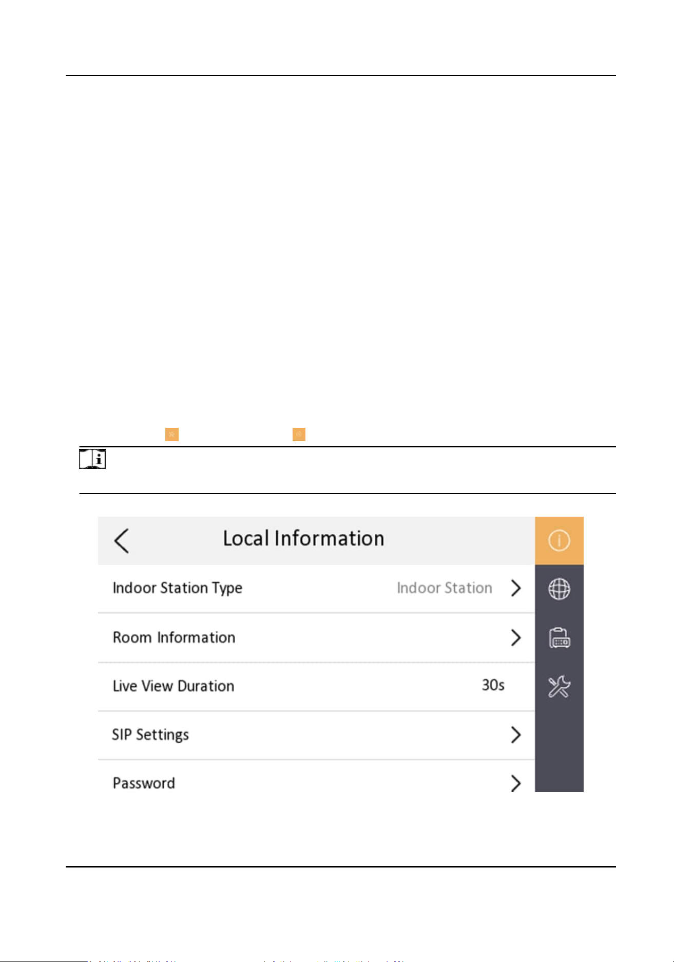
3.2.4 Set Local
Informaon
Indoor staon No. and the indoor extension No. are numbers, which can be dialed by other devices
to call the indoor staon and the indoor extension in an intercom system. The indoor staon No., is
composed of the oor No., room No., community No., building No. and unit No.
Up to 16 indoor extensions can be set for 1 indoor
staon.
Steps
1.
Tap
Sengs → → Conguraon → to enter the indoor staon No. sengs page.
Note
Default admin password is the acvaon password.
Figure 3-13 Local Informaon
Network Indoor Staon User Manual
18
2.
Select Indoor Staon to set the room informaon, live view duraon, SIP parameters and
password.
Room Informaon
You can set room name, room No. and in which way the room No. will be displayed. Tap
Advanced Sengs to set community No., building No., unit No. and oor No. if you need.
Note
●
Community No., building No., unit No. and oor No. can be omied if there is no such
informaon.
●
If there are two indoor staons that are in the same building, and should call each other,
enter the room No. directly to call.
●
If there are two indoor staons that are in two buildings, and should call each other, enter
the building No. and the room No. to call. For example, call 1-405 to call room 405 in
building 1.
Live View Duraon
You can set the duraon of live view.
SIP Sengs
You can set SIP parameters. For more details, please refer to: SIP Sengs
Password Sengs
You can set unlock password and duress code.
3.
Select Indoor Extension to set the room
informaon, live view duraon, registraon password
and enable SIP 1.0 according to your needs.
Room
Informaon
You can set room name and Extension No.
When calling the indoor staon and the two devices are in the same building, you can call the
Extension No. directly.
Live View
Duraon
You can set the duraon of live view.
Registraon Password
You can create a new registraon password.
Compable with SIP 1.0 indoor staon
You can tap to enable Compable with SIP 1.0 indoor staon according to your needs.
3.2.5 SIP
Sengs
Devices can communicate with each other via SIP protocol. You create set the SIP register
password, enable standard SIP and set VOIP account.
Network Indoor Staon User Manual
19
Steps
1.
Tap Sengs → → Conguraon , and enter admin (acvaon) password.
2.
Tap SIP Sengs in Local Informaon page.
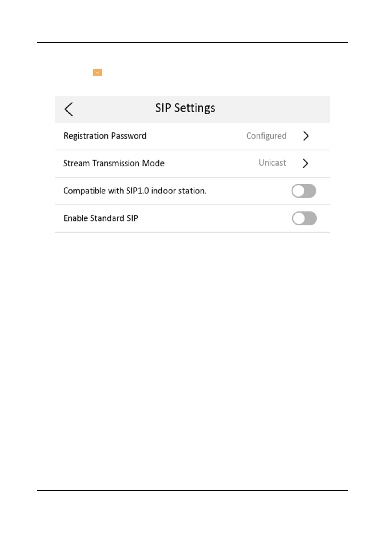
Figure 3-14 SIP Sengs
3.
Set SIP registraon password.
1) Tap Registraon Password.
2) Create a new SIP
registraon password and conrm the password.
3) Tap OK.
4.
Set Stream Transmission Mode as Unicast or
Muicast.
5.
Oponal: Tap to enable the funcon of compable with SIP 1.0 indoor staon.
6.
Oponal: Enable standard SIP.
1) Tap to Enable Standard SIP.
2) Tap VOIP Account Sengs and congure account informaon, including the user name, the
phone number, the registered user name, the password, the domain, the port No., and the
expiraon date.
Network Indoor Staon User Manual
20
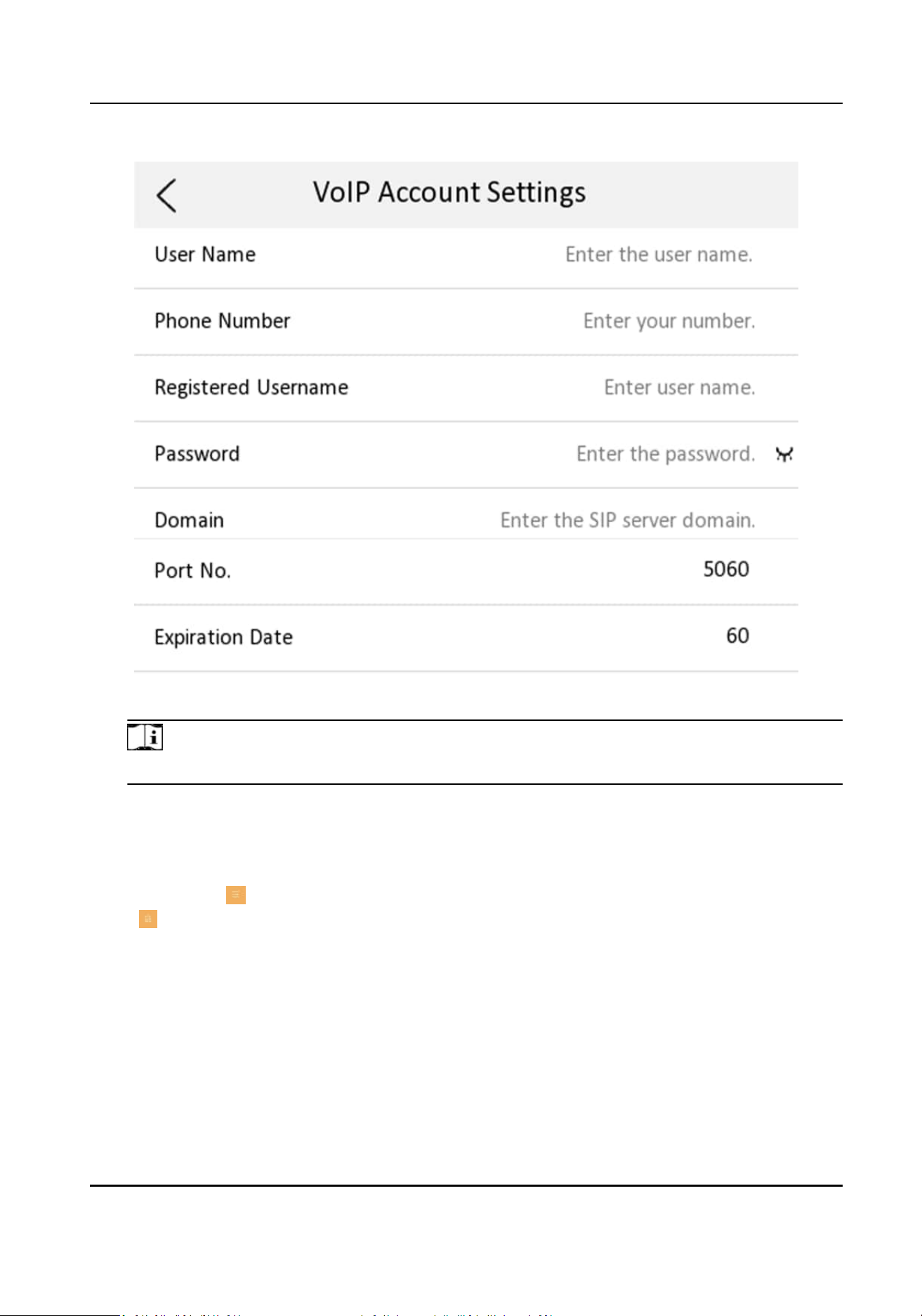
Figure 3-15 VOIP Account Sengs
Note
Up to 32 characters are allowed in the user name.
3.2.6 Add Camera
Steps
1.
Tap
Sengs → → Conguraon , and enter admin (acvaon) password.
2.
Tap to enter the device management page.
3.
Tap + to pop up the dialog box.
4.
Select a protocol to add the camera.
-
Select Private Protocoland you can add the camera depended on the Private Protocol .
Enter the device name, IP address, user name and the password of the camera. Edit port No.
and channel No.
Exit the page to save the
sengs.
-
Select Open Network Video Interface to add the camera.
Enter the device name, IP address, user name and the password of the camera.
Network Indoor Staon User Manual
21
Exit the page to save the sengs.
3.3 Password Sengs
3.3.1 Security Sengs
If you forgot the admin password, you can change your password via the reserved email address or
the security quesons.
Steps
1.
Tap
Sengs → → Conguraon , and enter the admin (acvaon) password to enter the
local informaon page. Tap → Security Sengs to enter security seng page.
2.
Tap Email Address. Enter or edit the address.
3.
Tap Security
Queson. Select quesons and enter the answers.
4.
Aer the sengs, you can reset your password via the reserved email address or via answering
quesons.
3.3.2 Modify Unlock/Duress Code
You can create and edit the duress code and unlock password of the indoor staon.
Steps
1.
Tap Sengs → → Conguraon , and enter admin (acvaon) password.
2.
Tap
→ Password to enter the password sengs page.
3.
Tap Unlock Password or Duress Code to pop up the password sengs dialog box.
Unlock Password
Create the indoor
staon's unlock password. If the device has connected to a lock, enter the
password to unlock.
Duress Code
When you are hijacked and forced to open the door, you can enter the duress code. An alarm
will be triggered to
nofy the management center secretly.
Note
The duress code and the unlock password cannot be the same.
4.
Create a new password and conrm it.
5.
Tap OK to save the sengs.
3.4 Device
Informaon
View the device informaon, including the version, model, serial No. and open source disclaimer.
Network Indoor Staon User Manual
22
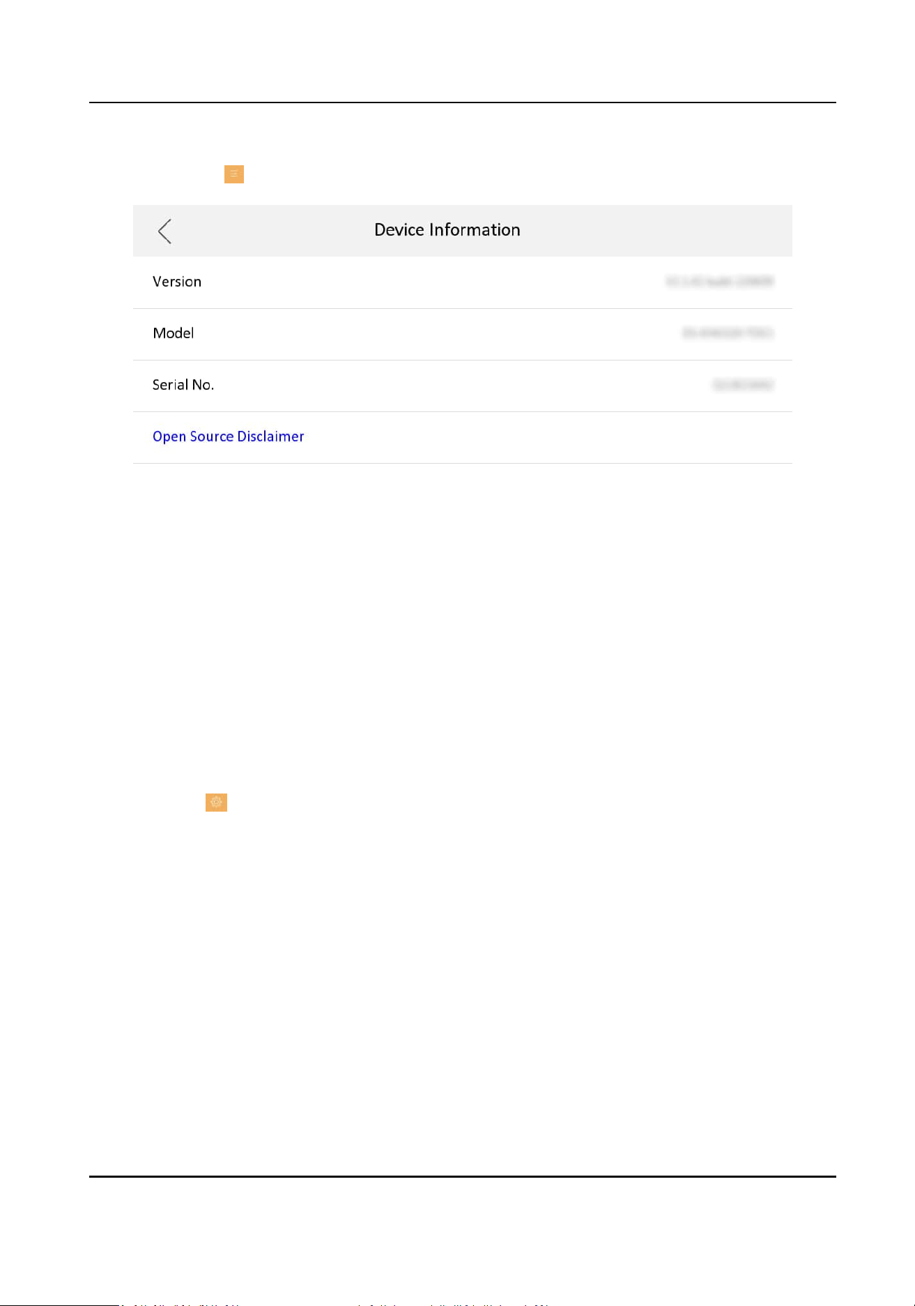
Steps
1.
Tap Sengs → → Device Informaon to enter the Device Informaon page.
Figure 3-16 Device Informaon
2.
View the device version, module, and serial No.
3.
Oponal: Tap Open Source Disclaimer to view the OSS statement.
3.5 General
Sengs
You can set me and date, system language and adjust the screen brightness on this page.
Tap Sengs → to enter the general sengs page.
Network Indoor Staon User Manual
23
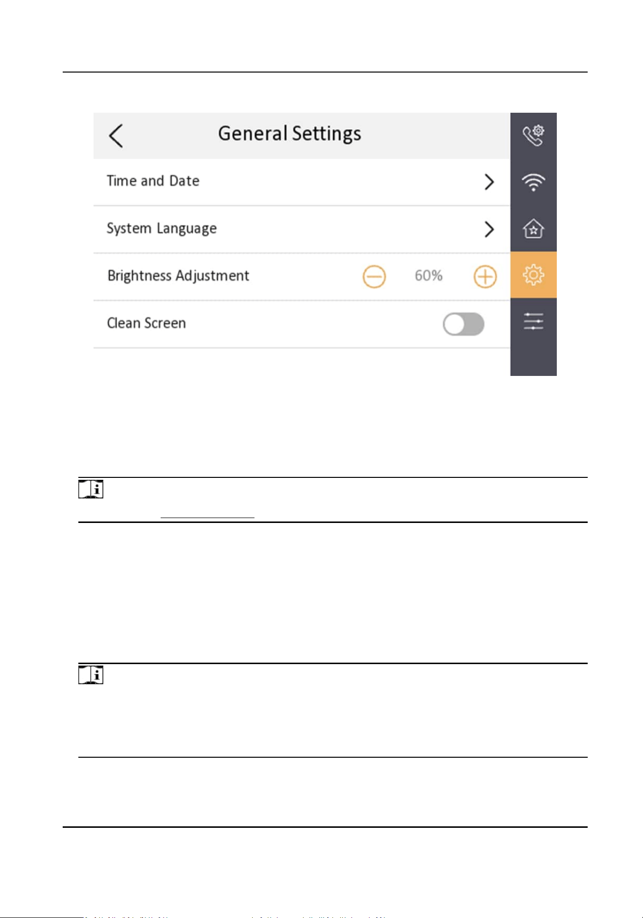
Figure 3-17 General Sengs
Time and Date
Set the displayed me and date format, current me. Tap Sync Time to synchronize the device
me. Tap to enable Synchronize Time to Door Staon to synchronize the device me to the
linked door
staon. You can also enable DST and set the DST start me, end me and bias.
Note
For details, see Synchronize Time .
System Language
Tap System Language to change the system language.
Brightness Adjustment
Tap + or - to adjust the screen brightness.
Clean Screen
Enable Clear Screen and the screen will be locked for 30s. And you can clear the screen within
the
me duraon.
Note
●
Aer enabling Clear Screen funcon, press and hold the Unlock key to exit the clear screen
mode.
●
The device without unlock key will exit the clear screen mode automacally when the me is
out.
Network Indoor Staon User Manual
24
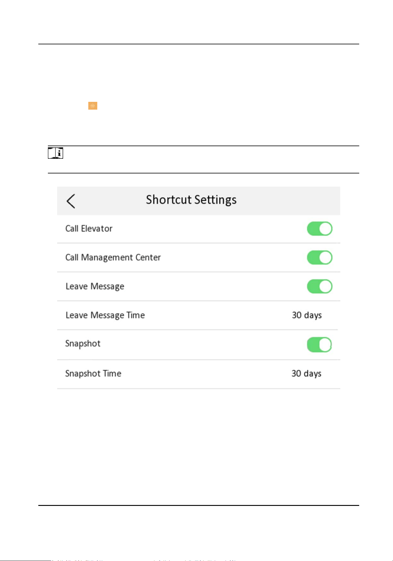
3.6 Preference
You can congure shortcut sengs and customizable buons on the preference page.
Tap Sengs → to enter the preference page.
Shortcut Sengs
You can enable Call Elevator, Call Management Center, Leave Message and Snapshot funcon,
and the icons will be displayed on the home page.
Note
You can set Leave Message Time and Snapshot Timeif these two funcons are enabled.
Figure 3-18 Shortcut Sengs
DIY Buon
You can customize funcons for four customizable touch-buon on the surface of the indoor
staon.
Network Indoor Staon User Manual
25
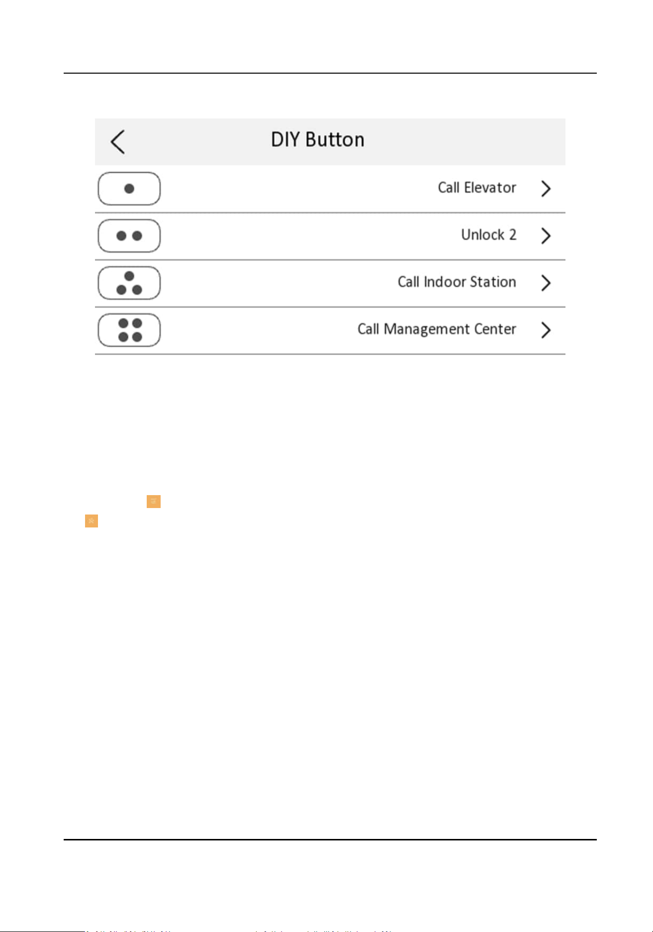
Figure 3-19 DIY Buon
3.7 System
Sengs
You can restore the device, unlink the APP, set mobile client services,etc.
Tap Sengs → → Conguraon , and enter the admin (acvaon) password.
Tap
to enter the system maintenance page.
Network Indoor Staon User Manual
26

Figure 3-20 System Maintenance
Restore
Restore Default Sengs
Tap Restore Default Sengs to restore parameters except network parameters and
acvaon password to factory sengs. And the system will reboot automacally.
Restore All
Tap Restore All to restore all parameters to factory sengs and the system will reboot
automacally.
Upgrade
Tap Upgrade to get the upgrade package online and reboot automacally.
Unlink APP Account
Aer unlinking APP account, you cannot operate via APP.
Wizard
Tap Wizard and set the language, network, indoor staon type, device No., and select a device
according to the wizard. Refers to
Quick Operaon for the details.
Network Indoor Staon User Manual
27
Hik-Connect Service Sengs
For more details, please refer to Link to the Mobile Client .
Security Sengs
Email Address
Tap Email Address. Enter or edit the address.
Security
Queson
Tap Security Queson. Select quesons and enter the answers.
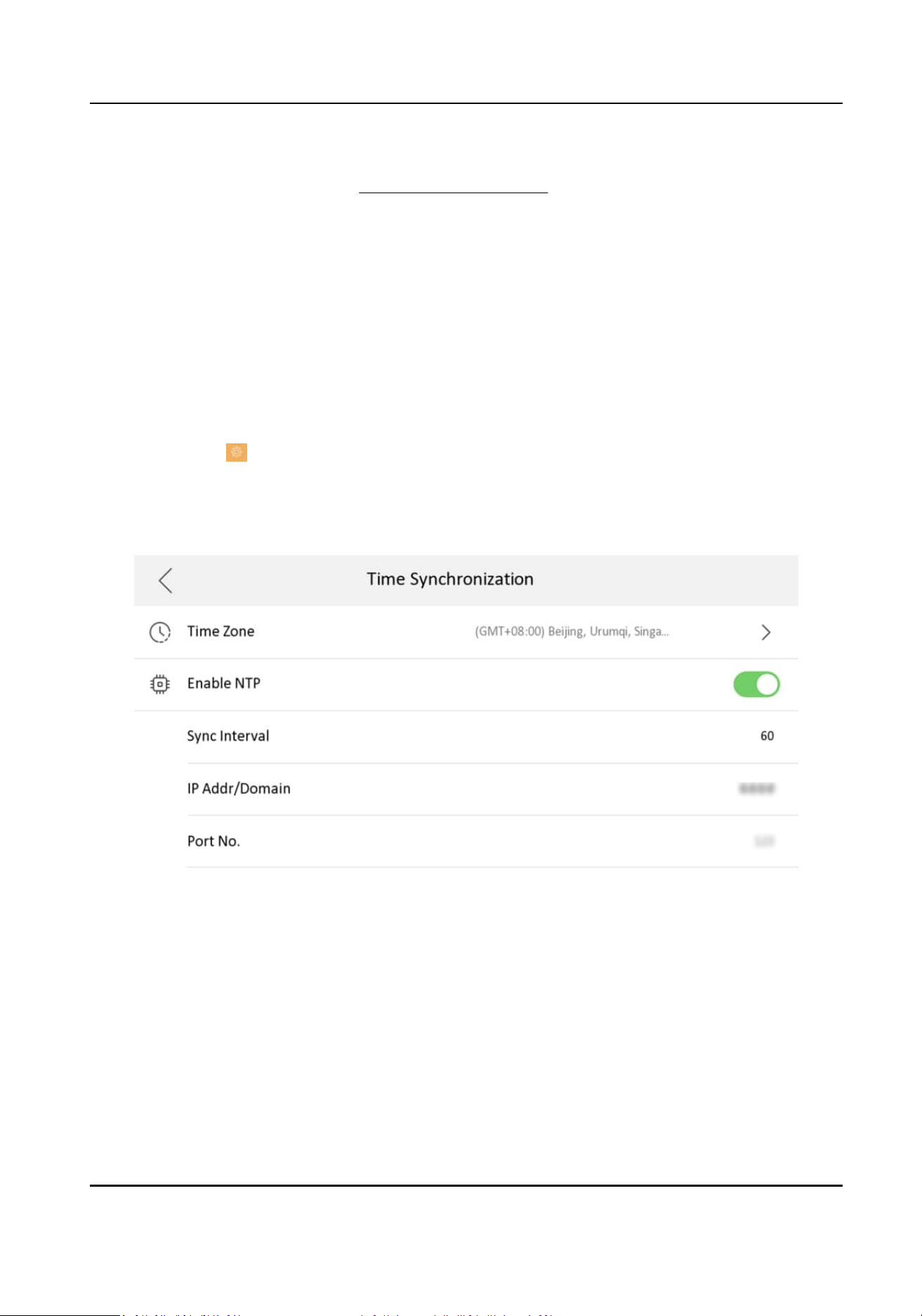
3.8 Synchronize Time
Steps
1.
Tap
Sengs → → Time and Date to enter the me synchronizaon page.
2.
Tap Date Format and Time Format to set the me format.
3.
Oponal: Tap Time to set me manually.
4.
Tap Sync Time.
Figure 3-21 Time Synchronizaon
1) Select the Time Zone.
2) Enable Enable NTP.
3) Set the synchronizing interval, enter the IP address/domain of NTP server and port No.
Network Indoor Staon User Manual
28
Note
●
The default unit of synchronizing interval is minute.
●
The me zone can be congured as well if the NTP is not enabled.
3.9 Sound Sengs
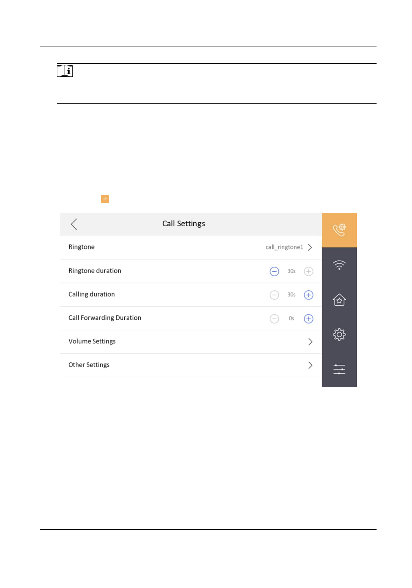
3.9.1 Call Sengs
You can set the ringtone, ring duraon, call forwarding me on call sengs page.
Steps
1.
Tap
Sengs → to enter the call sengs page.
Figure 3-22 Call Sengs
2.
Set corresponding parameters.
Ringtone
There are 3 ringtones by default, and you can custom and import at most 4 ringtones via
Batch
Conguraon Tool or iVMS-4200 Client Soware.
Ringtone Duraon: The maximum duraon of indoor staon when it is called without being
accepted. Ringtone
duraon ranges from 10 s to 60 s.
Calling Duraon
Network Indoor Staon User Manual
29
The call will end automacally when the actual calling duraon is longer than the congured
one. Calling duraon ranges from 30 s to 60 s.
Call Forwarding Duraon
The ring duraon limit beyond which the call is automacally forwarded to the mobile phone
designated by the resident. Call forwarding ranges from 0 s to 20 s.
Other Sengs
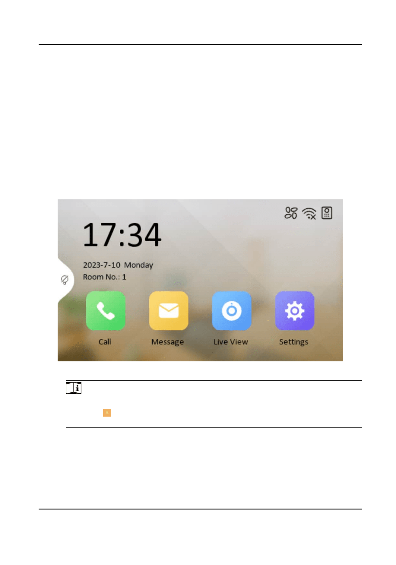
You can set the Do Not Disturb and Auto-answer funcons.
Auto-answer
Enable Auto-answer. Aer enabling, the call from door staon/villa door staon will be
answered by the indoor staon automacally. The caller from door staon/villa door
staon can leave voice messages. Aer the message is le, you can check it from Message
on the main page of the device.
Figure 3-23 Main Page
Note
Before enabling Auto-answer, the funcon of Leave Message needs to be enabled. Tap
Sengs → → to enter the shortcut sengs page. Eanble Leave Message and go back to
calling sengs page to enable Auto-answer.
Do Not Disturb Device
Select All and all devices will not disturb this device. Select Indoor Staon and all indoor
staon will not disturb this device.
Do Not Disturb
Network Indoor Staon User Manual
30
Set the do not disturb schedule. Select Close and the do not disturb funcon will not be
enabled. Select All Day and this device will not be disturbed all day. Select Schedule and
you can set the do not disturb me duraon. Within the congured me, this device will
not be disturbed.
Note
Indoor extension does not support the ring duraon sengs, call forwarding sengs, or auto-
answer funcon.
3.9.2 Volume Sengs
Set the microphone volume, prompt sound volume and call volume.
Steps
1.
Tap
Sengs → → Volume Sengs to enter the volume sengs page.
2.
Set the microphone volume, prompt sound volume, and the call volume of the indoor staon.
3.
Oponal: Enable Touch Sound to turn on the sound when you touch device screen.
3.10 Via the mobile client
The device support adding to Hik-Connect and coguraon remotely via the client.
3.10.1 Link to the Mobile Client
Before You Start
Note
The funcon of the device varies according to different models. Refers to the actual device for
detailed informaon.
Steps
1.
Tap
Sengs → → Conguraon → → Hik-Connect Service Sengs to enter the sengs
page.
Note
Admin password is required to enter the conguraon page.
2.
Enable Enable Hik-Connect Service.
Network Indoor Staon User Manual
31
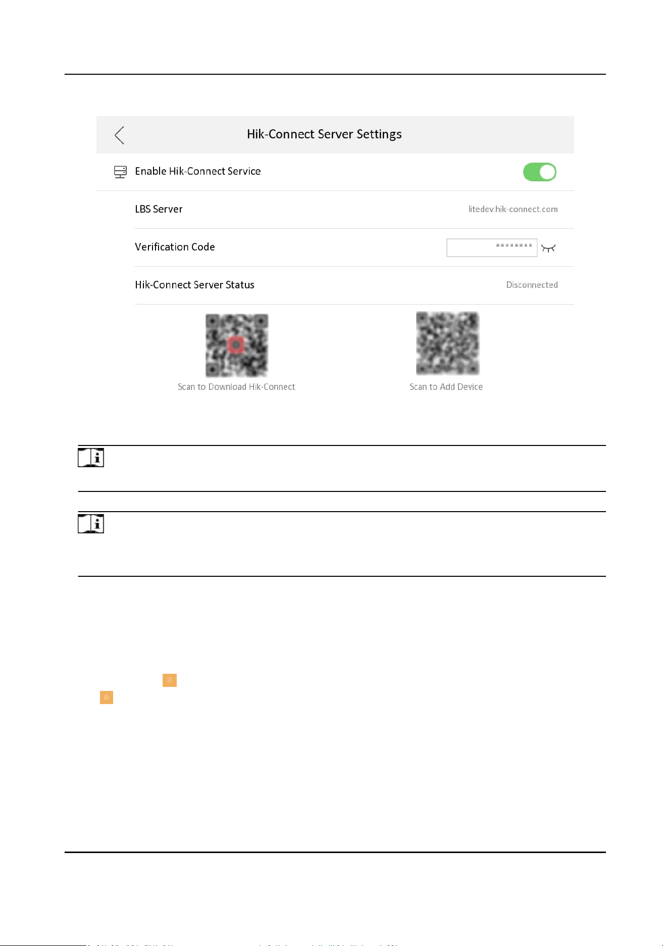
Figure 3-24 Enable Guarding Vision Service
3.
Edit LBS server and Vericaon Code.
Note
Vericaon code is used to add the device to mobile client.
4.
Oponal: Scan the QR code on the screen.
Note
●
Scan the le QR code on the screen to access Hik-Connect.
●
Scan the right QR code on the screen to add the device to the mobile client.
3.10.2 Unlink the Account
Remove the account from the mobile client.
Steps
1.
Tap Sengs → → Conguraon , and enter the admin (acvaon) password.
2.
Tap to enter the system maintenance page.
Network Indoor Staon User Manual
32
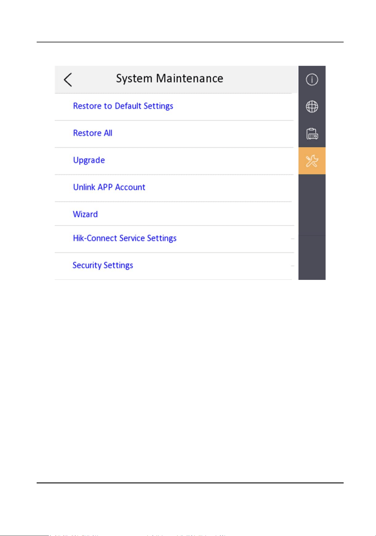
Figure 3-25 System Maintenance
3.
Tap Unlink App Account, and follow the steps on the page.
Network Indoor Staon User Manual
33
Chapter 4 Local Operaon
4.1 Call Sengs
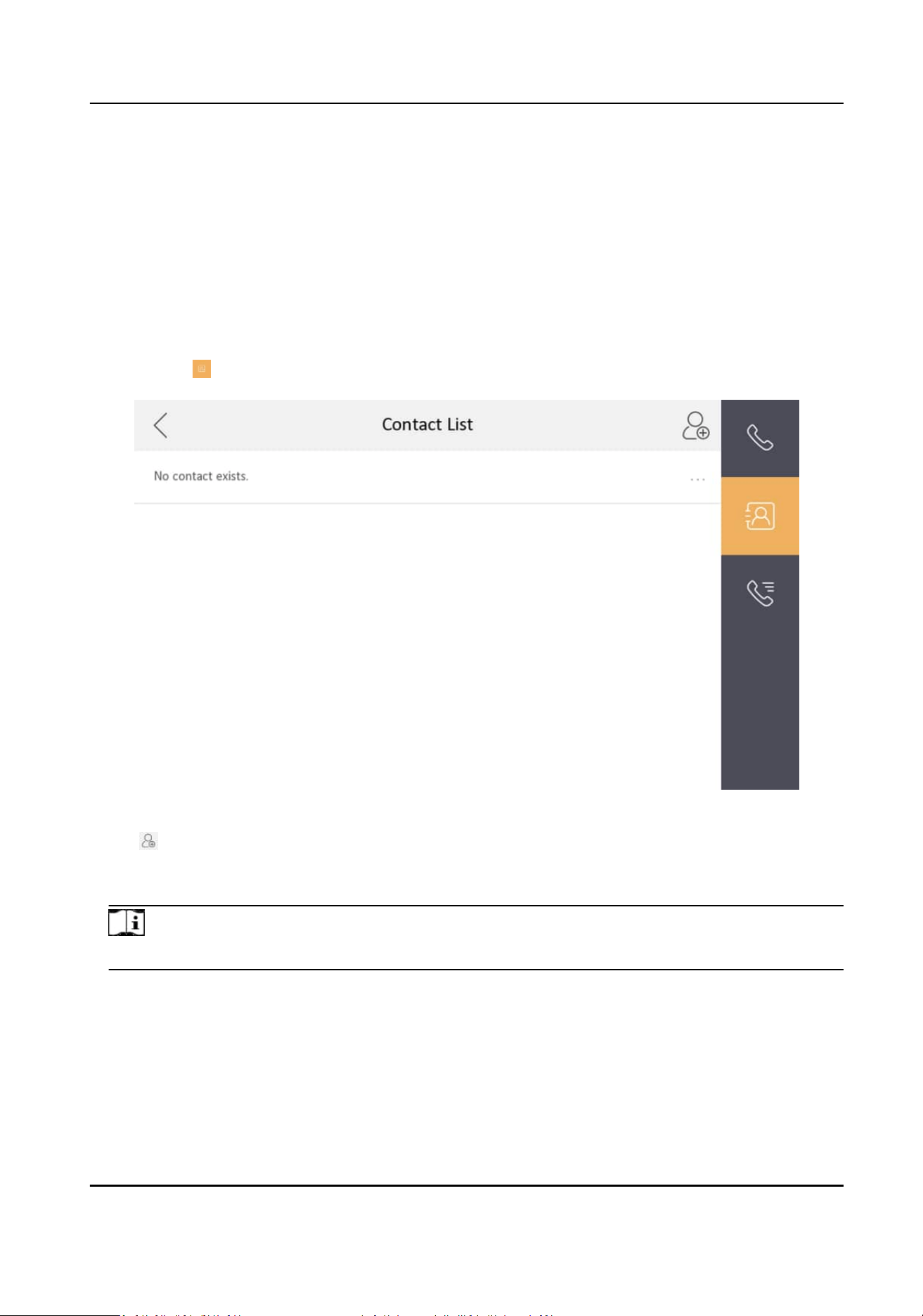
4.1.1 Add Contact
Steps
1.
Tap Call → to enter the contact list page.
Figure 4-1 Contact List
2.
Tap to pop up the contact adding dialog.
3.
Enter the contact name and the room No.
4.
Tap OK to save the
sengs.
Note
Up to 200 contacts can be added.
Network Indoor Staon User Manual
34
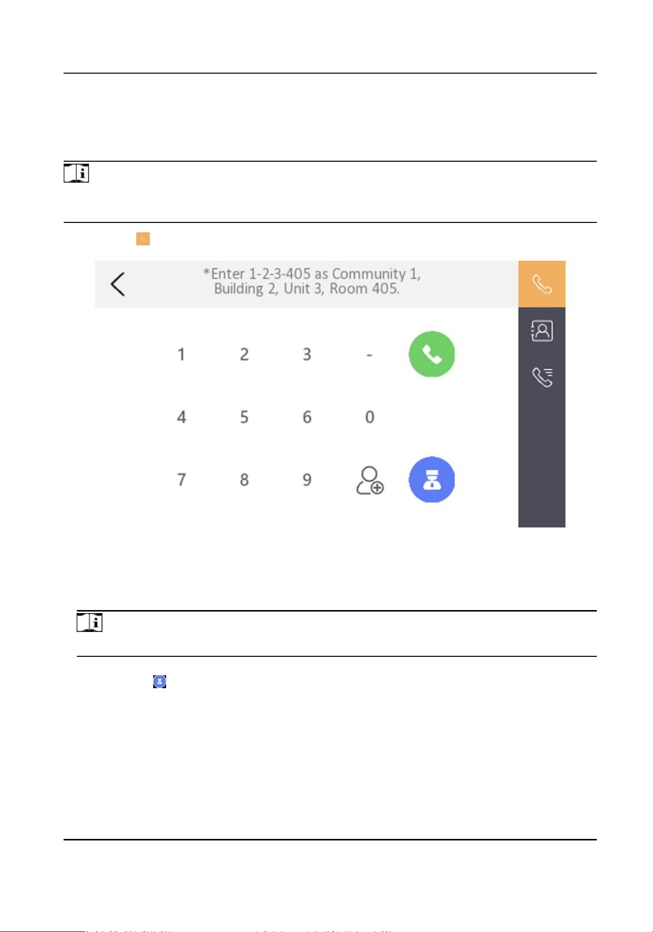
4.1.2 Call Resident
Steps
Note
Only when the Call Management Center funcon is enabled, should the call center buon be
displayed. For details, see the conguraon guide.
1.
Tap Call → to enter the residents calling page.
Figure 4-2 Call Resident
2.
Enter the calling number.
The calling number format should be x-x-x-xxx. For example, the calling number of Community 1,
Building 2, Unit 3, and Room 405 is 1-2-3-405.
Note
The community No. can be omied.
3.
Tap the call buon to start an audiovisual call.
4.
Oponal: Tap to call management center.
4.1.3 Call Indoor Extension/Indoor
Staon
Tap Call on the main page to enter the calling page.
If you install indoor staon and indoor extensions at home, you can call the indoor extension via
your indoor
staon, and vice versa.
Network Indoor Staon User Manual
35
Enter 【0-indoor extension No.】 on the indoor staon to start calling.
Enter 【0-0】 to call the indoor staon from the indoor extension.
4.1.4 Receive Call
The indoor staon and indoor extension can receive calls from the analog doorphone, the door
staon, the main staon or iVMS-4200 Client.
On the call from door staon page, there are 2 unlock buons: Unlock 1, and Unlock 2. When you
tap Unlock 1, the building gate will open by default, and when you tap Unlock 2, the door
connected to the door
staon with the secure control door unit will open.
Tap the capture
buon to capture and save the live view picture when speaking with the door
staon.
On the call from the analog doorphone page, you can tap the unlock buon to open the connected
door lock and tap the capture
buon to capture and save the live view pictures.
Indoor extension can receive calls from the door staon and the main staon only.
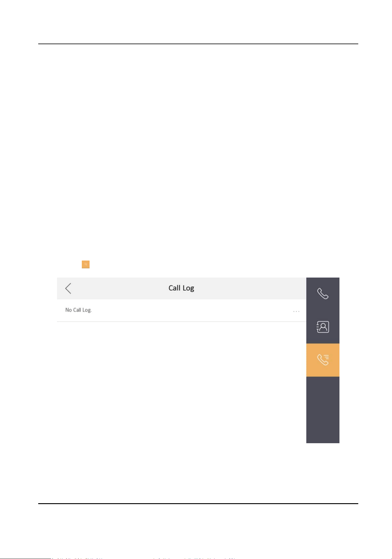
4.1.5 View Call Logs
Steps
1.
Tap Call →
to enter the call log page.
Figure 4-3 Call Logs
2.
Tap a piece of call logs in the list to call back.
Network Indoor Staon User Manual
36
Note
●
Indoor extension does not support this funcon.
●
The indoor staon saves call logs from analog doorphones, door staons, outer door staons,
management center and other indoor staons.
●
Hold a piece of call logs to open the call logs handling menu. Tap Delete to delete the piece of
call logs. Tap Clear to delete all pieces of call logs.
4.2 Leave Message
You can set leave message, and view the messages.
Tap Sengs → → Shortcut Sengs , and enable Leave Message.
Set Leave Message Time as 1 day, 7 days or 30 days.
Tap Message →
to view the visitor messages.
4.3 Live View
On the live view page, you can view the live video of linked door staons and network cameras.
Steps
Note
Make sure the network camera or the door staon is well-connected.
1.
Tap Live View to enter the live view page.
Network Indoor Staon User Manual
37
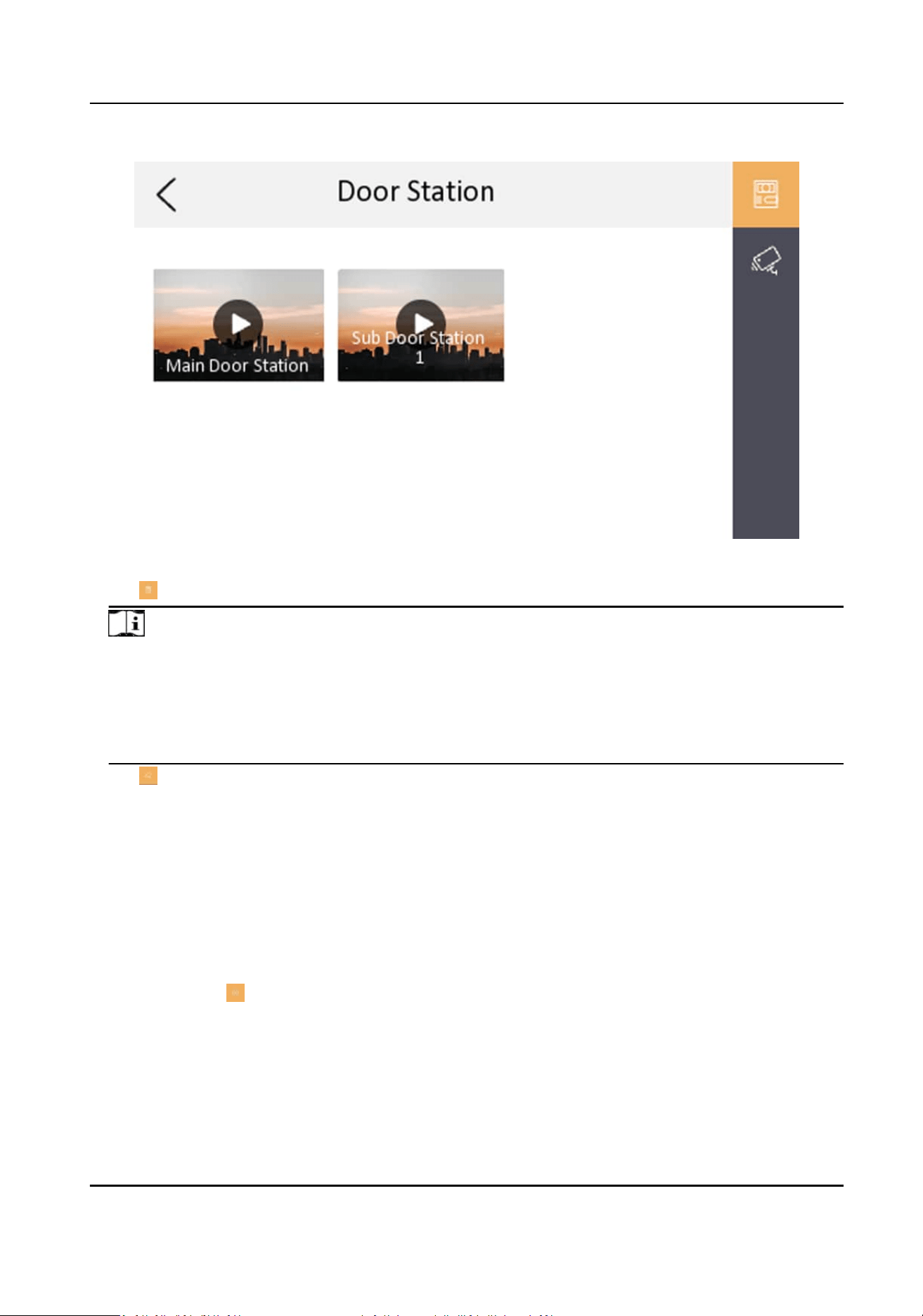
Figure 4-4 Live View
2.
Tap to enter the live view page of the door staon.
Note
●
On the Call from Door Staon page, there are 2 unlock buons: Unlock 1, and Unlock 2. When
you tap Unlock 1, the building gate will open by default. When you tap Unlock 2, the door
staon connected door will open.
●
On the Call from Door
Staon page, there is 1 capture buon. You can tap the buon to
capture the picture via door
staon.
3.
Tap to enter the live view page of network cameras.
4.4 Call Elevator
The indoor staon supports calling the elevator.
Before You Start
Enable call elevator via iVMS-4200 Client
Soware.
Steps
1.
Tap
Sengs → → Shortcut Sengs to enable Call Elevator.
Network Indoor Staon User Manual
38
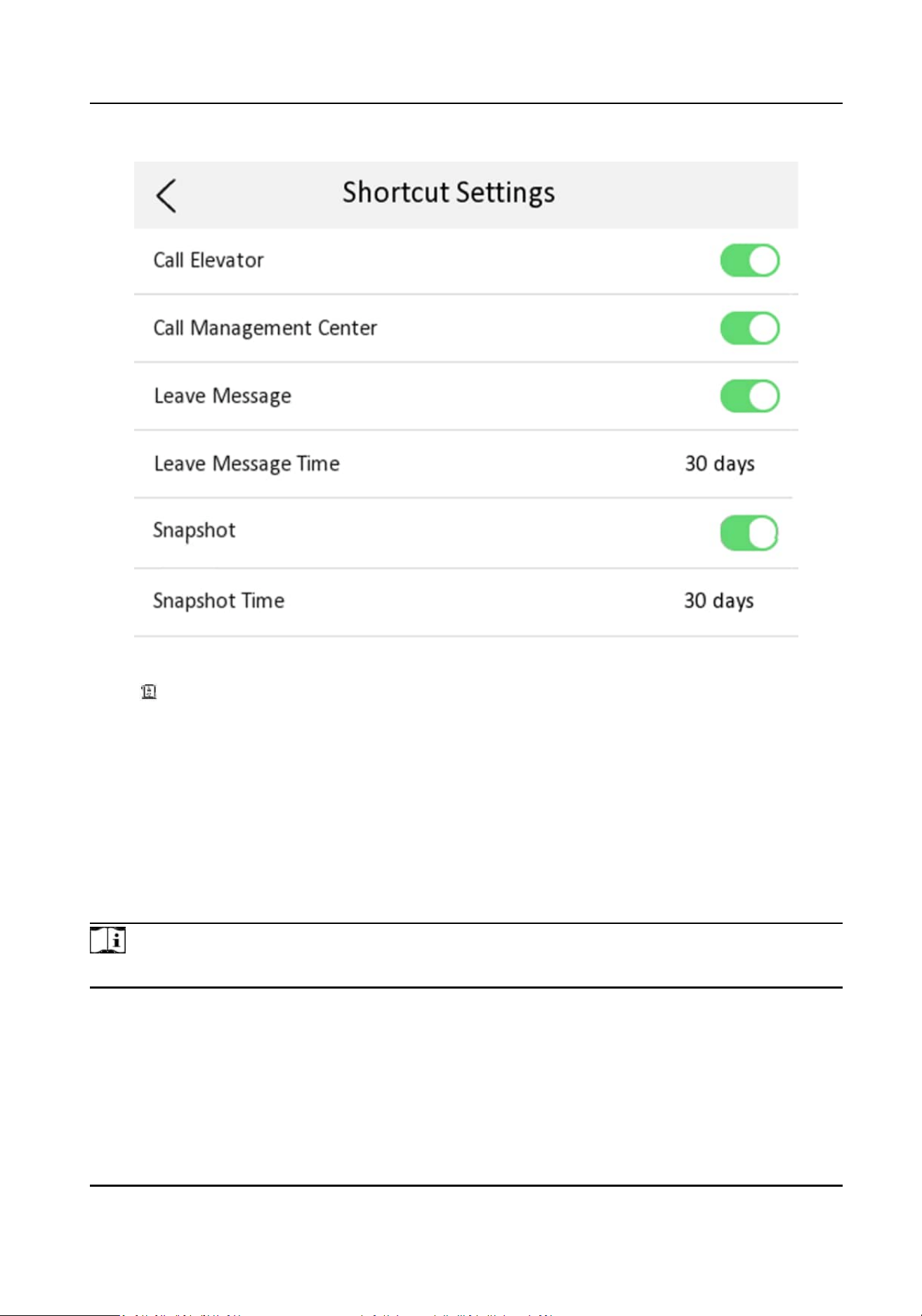
Figure 4-5 Call Elevator
2.
Tap on the home page of the indoor staon to start calling the elevator.
3.
When the device communicates with door staon, tap unlock icon to start calling the elevator.
4.5
Informaon Management
You can view public noce, visitor message, and capture log on informaon management page.
Tap Message to enter the
informaon management page.
Delete a Log: Hold the item, you can delete it.
Clear Logs: Hold the item, you can clear all logs.
Note
Indoor extension only supports capture log.
Network Indoor Staon User Manual
39
Chapter 5 Client Soware Conguraon
5.1 Device Management
Device management includes device acvaon, adding device, eding device, and deleng device,
and so on.
Aer running the iVMS-4200, video intercom devices should be added to the client soware for
remote conguraon and management.
5.1.1 Add Video Intercom Devices
Steps
Note
●
You can add at most 512 indoor staons and main staons in total to the client, and add at most
16 door staons to the client.
●
For video intercom devices, you are required to create the password to acvate them before
they can be added to the
soware and work properly.
●
You can add online video intercom devices, and add them manually. Here take adding online
video intercom devices as example.
1.
Click Maintenance and Management → Device Management to enter the device management
page.
2.
Click the Device tap.
3.
Click Add to add the device to the client.
Network Indoor Staon User Manual
40
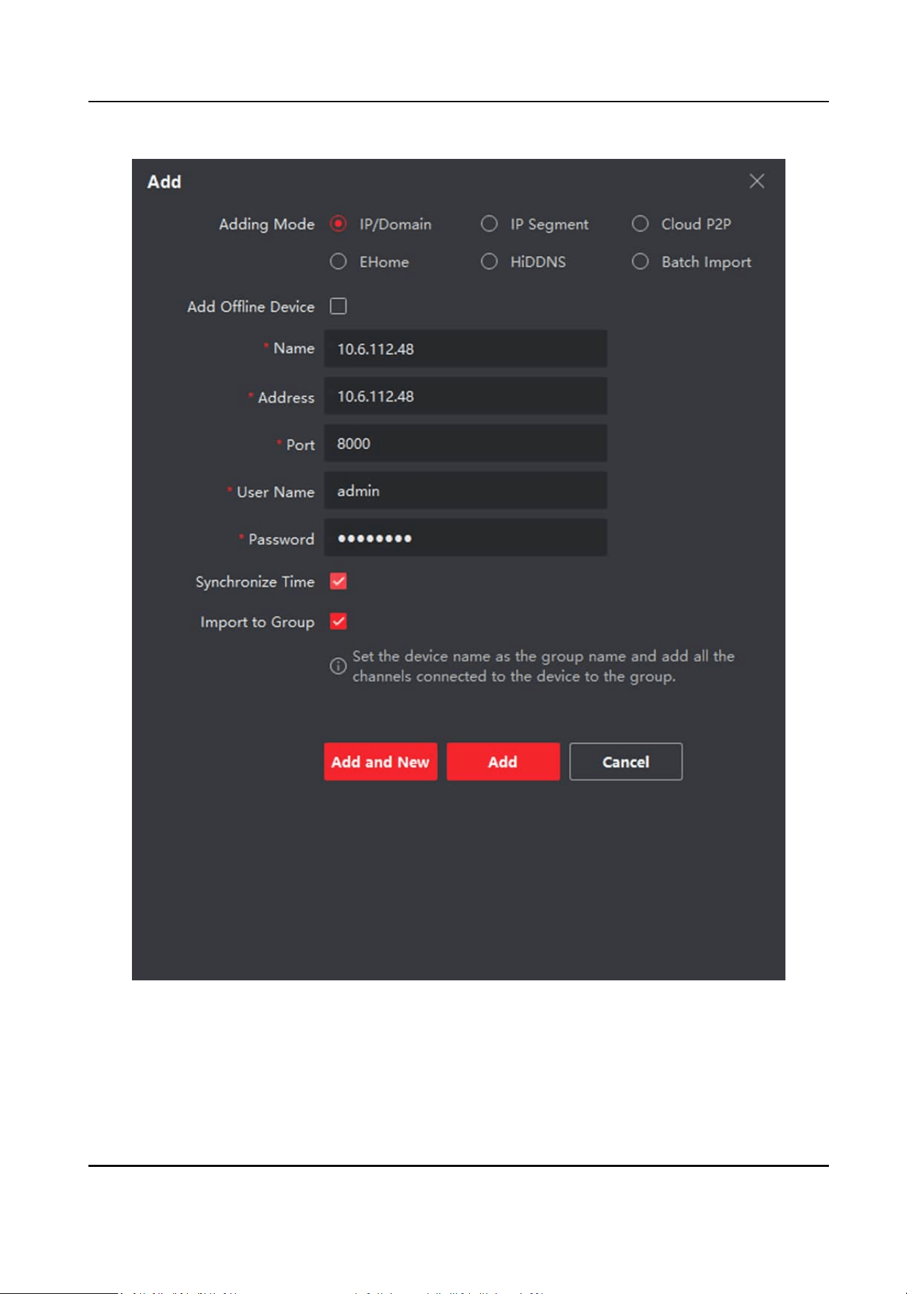
Figure 5-1 Add the Device
4.
Oponal: Click Online Device, the acve online devices in the same local subnet with the client
soware will be displayed on the Online Device area.
Network Indoor Staon User Manual
41
Note
To add online devices to the soware, you are required to change the device IP address to the
same subnet with your computer rst.
1) You can click Refresh Every 60s to refresh the informaon of the online devices.
2) Select the devices to be added from the list.
3) Click Add to Client to add the device to the client.
5.
Input the required
informaon.
Nickname
Edit a name for the device as you want.
Address
Input the device's IP address. The IP address of the device is obtained automacally in this
adding mode.
Port
Input the device port No. The default value is 8000.
User Name
Input the device user name. By default, the user name is admin.
Password
Input the device password.
6.
Oponal: You can check the checkbox Export to Group to create a group by the device name. All
the channels of the device will be imported to the corresponding group by default.
The client also provides a method to add the
oine devices. Check the checkbox Add Oine
Device, input the required informaon and the device channel number and alarm input number,
and then click Add. When the oine device comes online, the soware will connect it
automacally.
Note
●
Add Mulple Online Devices: If you want to add mulple online devices to the client soware,
click and hold Ctrl key to select mulple devices, and click Add to Client to open the device
adding dialog box. In the pop-up message box, enter the user name and password for the
devices to be added.
●
Add All the Online Devices: If you want to add all the online devices to the client soware,
click Add All and click OK in the pop-up message box. Then enter the user name and password
for the devices to be added.
5.1.2 Modify Network Informaon
Select the device from the device list, click , and then you can modify the network informaon
of the selected device.
Network Indoor Staon User Manual
42

Note
You should enter the admin password of the device in the Password eld of the pop-up window to
modify the parameters.
5.2 System Conguraon
You can congure the video intercom parameters accordingly.
Steps
1.
Click Maintenance and Management → System Conguraon → ACS & Video Intercom to
enter the system
conguraon page.
2.
Enter the required informaon.
Ringtone
Click ... and select the audio le from the local path for the ringtone of indoor staon.
Oponally, you can click for a tesng of the audio le.
Ringtone Duraon
Enter ringtone duraon, ranging from 15 seconds to 60 seconds.
Max. Speaking
Duraon with Indoor Staon
Enter the maximum duraon of speaking with the indoor staon, ranging from 120 seconds
to 600 seconds.
Max. Speaking Duraon with Door Staon
Enter the maximum duraon of speaking with the door staon, ranging from 90 seconds to
120 seconds.
Max. Speaking
Duraon with Access Control Device
Enter the maximum duraon of speaking with the access control device, ranging from 90
seconds to 120 seconds.
3.
Click Save to enable the
sengs.
4.
Oponal: Click Default to restore the default parameters.
5.3 Remote
Conguraon
In the device list area, select a device and click to enter the remote conguraon page.
5.3.1 System
Click System on the remote conguraon page to display the device informaon: Device
Informaon, General, Time, System Maintenance, User, RS-485, and Security.
Network Indoor Staon User Manual
43
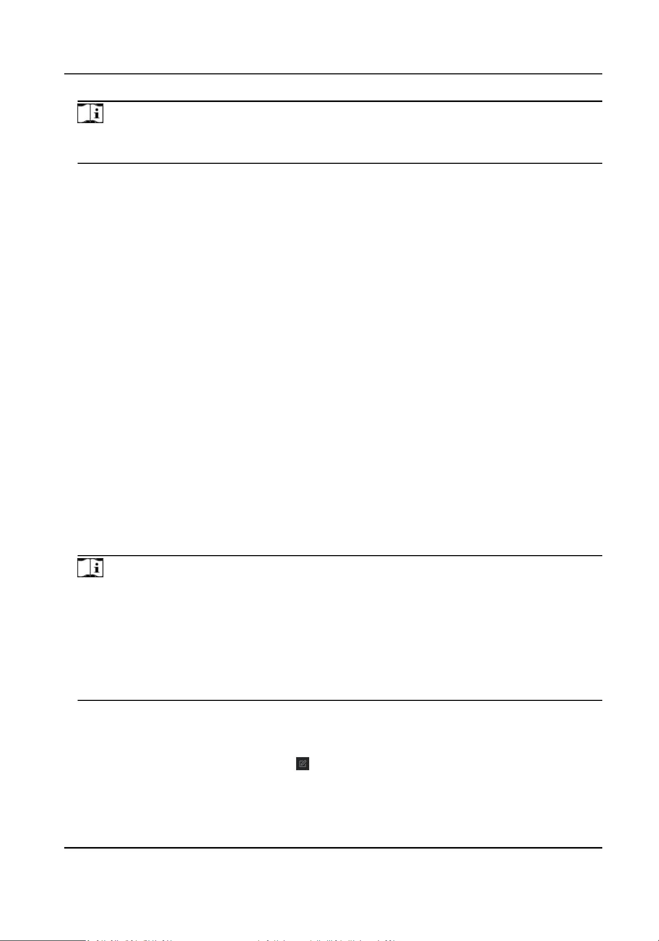
Device Informaon
Click Device Informaon to enter device basic informaon page. You can view basic informaon
(the device type, and serial No.), and version informaon of the device.
Figure 5-2 Device
Informaon
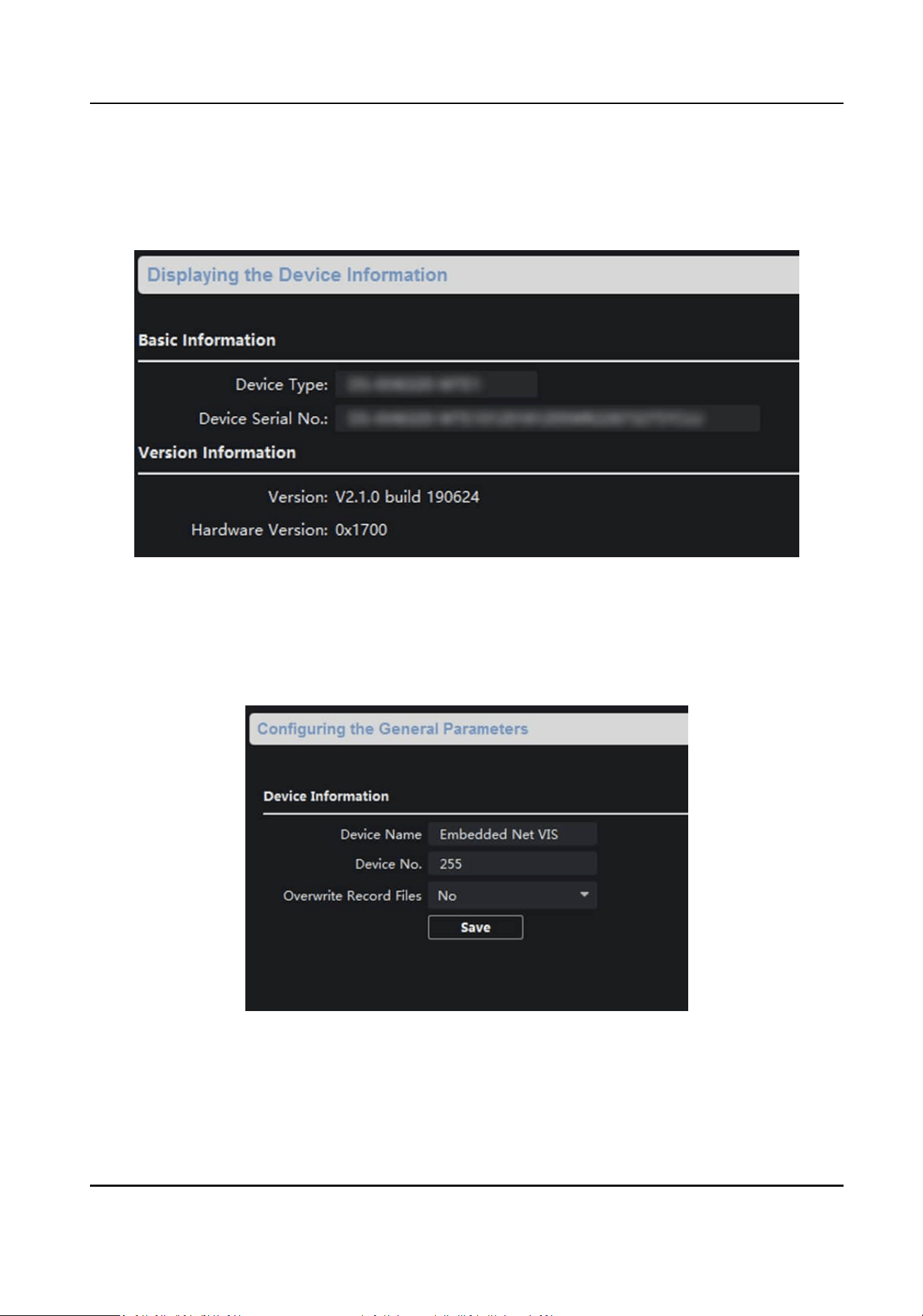
General
Click General to enter device general parameters sengs page. You can view and edit the device
name and device ID, and select overwrite record
le.
Figure 5-3 General
Time
Click
Time to enter the device me sengs page.
Network Indoor Staon User Manual
44
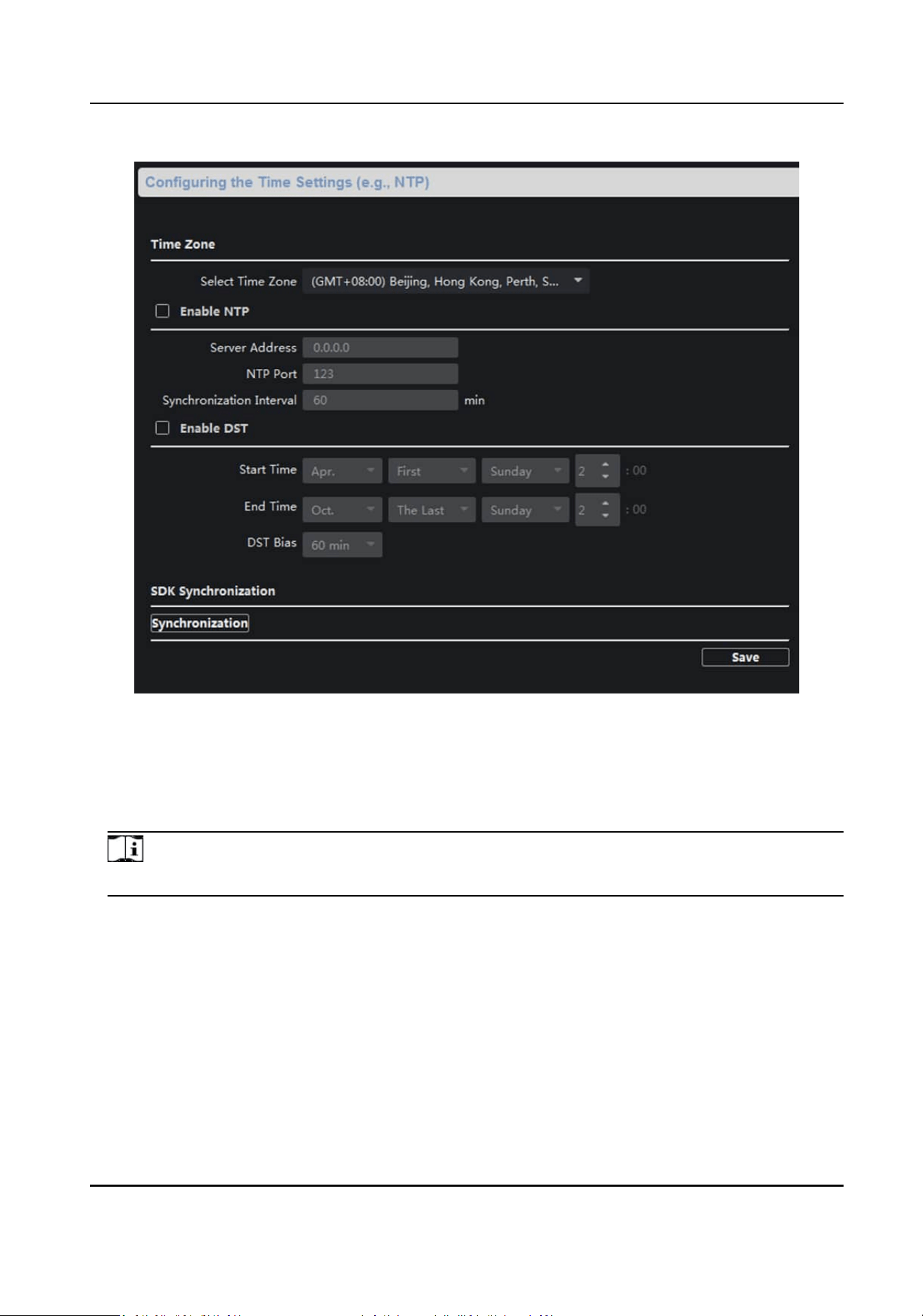
Figure 5-4 Time Sengs Page
Select Time Zone, Enable NTP, Enable DST, or SDK Synchronizaon. Click Save to save the me
sengs.
●
Time Zone: Select a me zone from the drop-down list menu.
●
NTP: Click Enable NTP, and enter the server address, NTP port, and
synchronizaon interval.
Note
The default port No. is 123.
●
DST: Click Enable DST, and set the start
me, end me, and bias.
●
SDK Synchronizaon: Click Synchronizaon, and the system will synchronize the data to the SDK.
System Maintenance
Click
System Maintenance to enter the page.
Network Indoor Staon User Manual
45
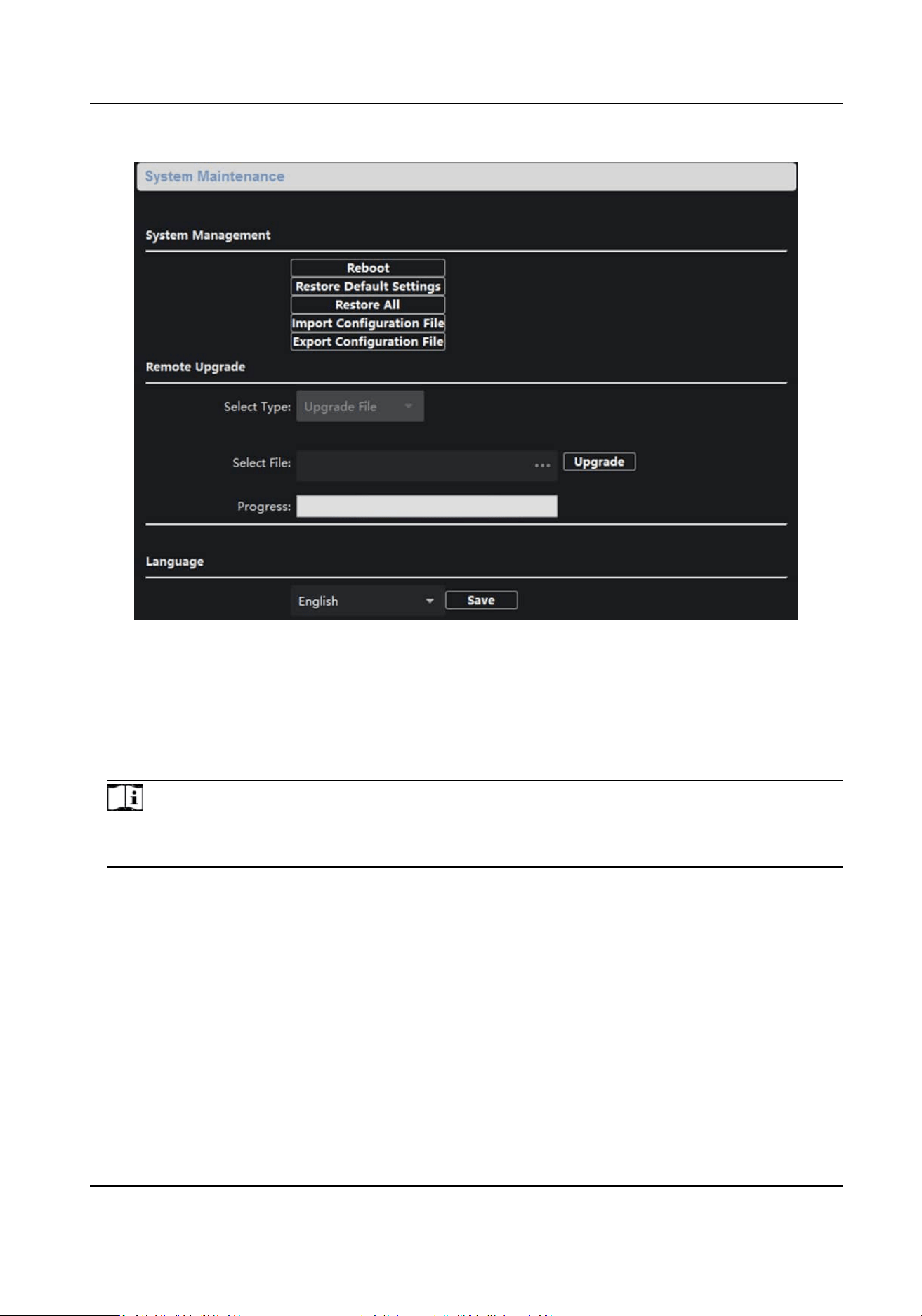
Figure 5-5 System Maintenance
●
Reboot: Click Reboot and the system reboot dialog box pops up. Click Yes to reboot the system.
●
Restore Default Sengs: Click Restore Default Sengs to restore the default parameters. All
default
sengs, excluding network parameters, will be restored.
●
Restore All: Click Restore All to restore all parameters of device and reset the device to inacve
status.
Note
all default sengs, including network parameters, will be restored. The device will be reset to
inacvated status.
●
Import Conguraon File: Click Import Conguraon File and the import le window pops up.
Select the path of remote
conguraon les. Click Open to import the remote conguraon le.
The conguraon le is imported and the device will reboot automacally.
●
Export
Conguraon File: Click Export Conguraon File and the export le window pops up.
Select the saving path of remote conguraon les and click Save to export the conguraon
le.
●
Remote Upgrade: Click ... to select the upgrade le and click Upgrade to remote upgrade the
device. The process of remote upgrade will be displayed in the process bar.
●
Language: Select a language, and click Save to change the device system language.
Network Indoor Staon User Manual
46
Note
○
The device supports 19 languages: English, French, Brazilian Portuguese, Spanish, Russian,
German, Italian, Polish, Arabic, Turkish, Vietnamese, Ukrainian, Hungarian, Dutch, Romanian,
Czech, Bulgarian, Croaan, Serbian.
○
Reboong the device is required aer you change the system language.
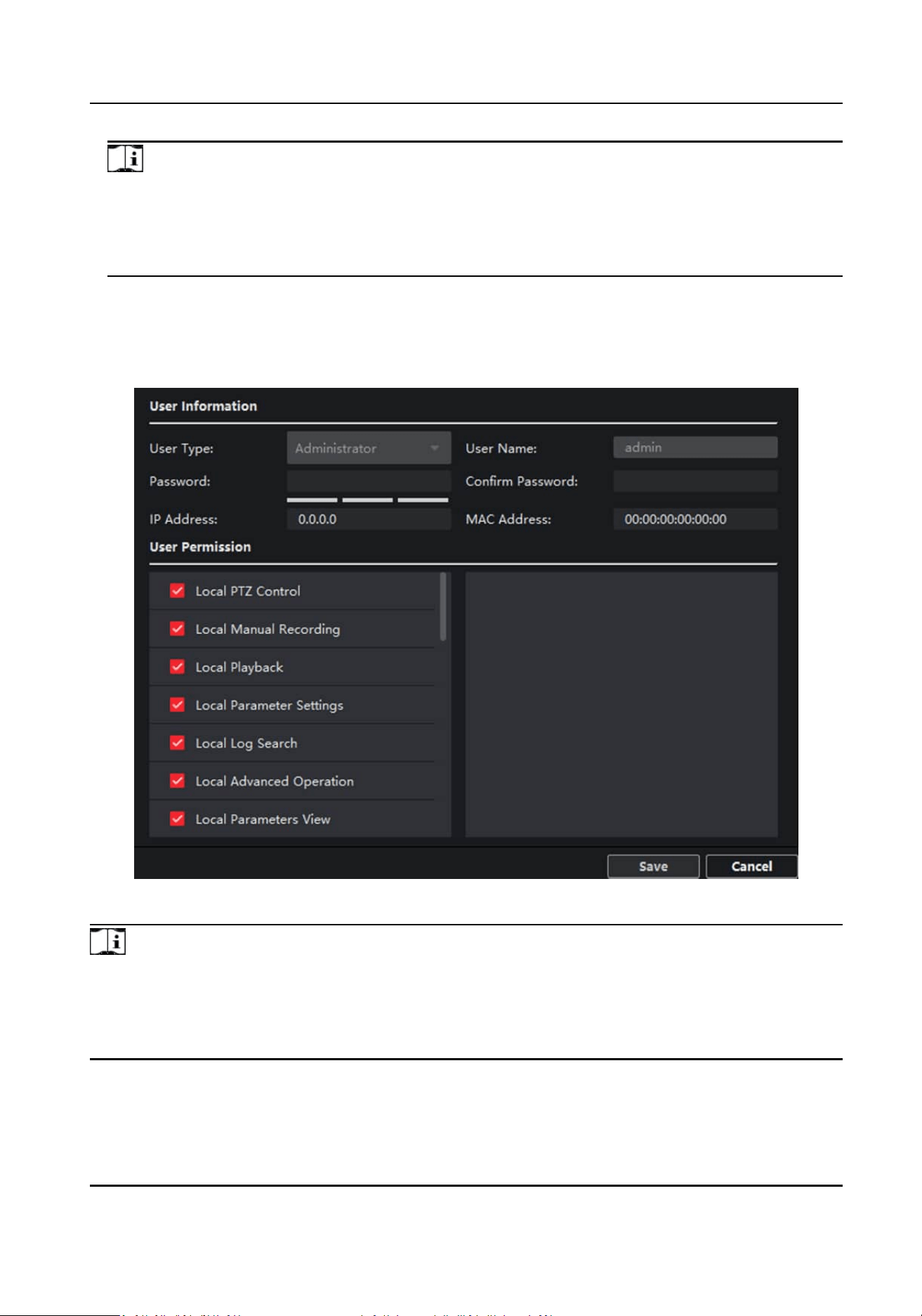
User
Click User to enter the user informaon eding page.
Select the user to edit and click Edit to enter the user parameter page.
Figure 5-6 User Page
Note
●
The new password and conrm password should be idencal.
●
Aer eding the password of device, click refresh buon from the device list, the added device
will not be there. You should add the device again with new password to operate the remote
conguraon.
Network Indoor Staon User Manual
47
Security
Click Security to enter the page. You can enable SSH or enable HTTPS on this page.
Click Save aer conguraon.
5.3.2 Video Intercom
Click Video Intercom on the remote conguraon page to enter the video intercom parameters
sengs: Time Parameters, Password, Zone Conguraon, IP Camera Informaon, Volume Input
and Output Conguraon, Ring, Arming Informaon, Calling Linkage, Relay, and SIP No.
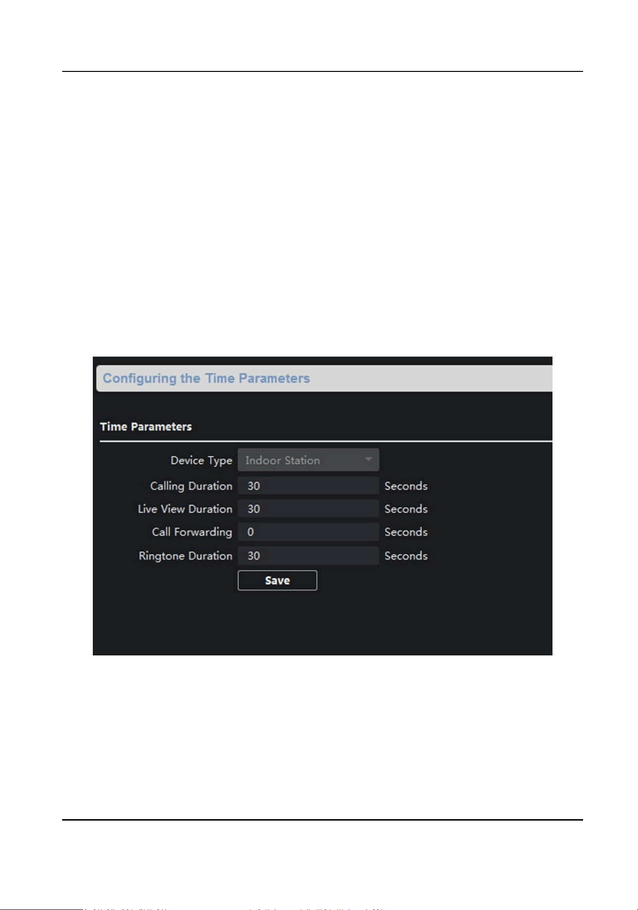
Time Parameters
Steps
1.
Click Time Parameters to enter
me parameters sengs page.
Figure 5-7 Time Parameters
2.
Congure the calling duraon, live view duraon, call forwarding me, and the ringtone
duraon.
3.
Click Save.
Network Indoor Staon User Manual
48
Note
●
Calling duraon is the maximum duraon of indoor staon when it is called without being
received. The range of maximum ring duraon varies from 30s to 60s.
●
Live view duraon is the maximum me of playing live view of the indoor staon. The range of
maximum live view
me varies from 10s to 60s.
●
Call forwarding refers to the ring
duraon limit beyond which the call is automacally
forwarded to the mobile phone designated by the resident. The range of call forwarding me
varies from 0s to 20s.
●
For indoor extension, it only requires
seng the maximum live view me.
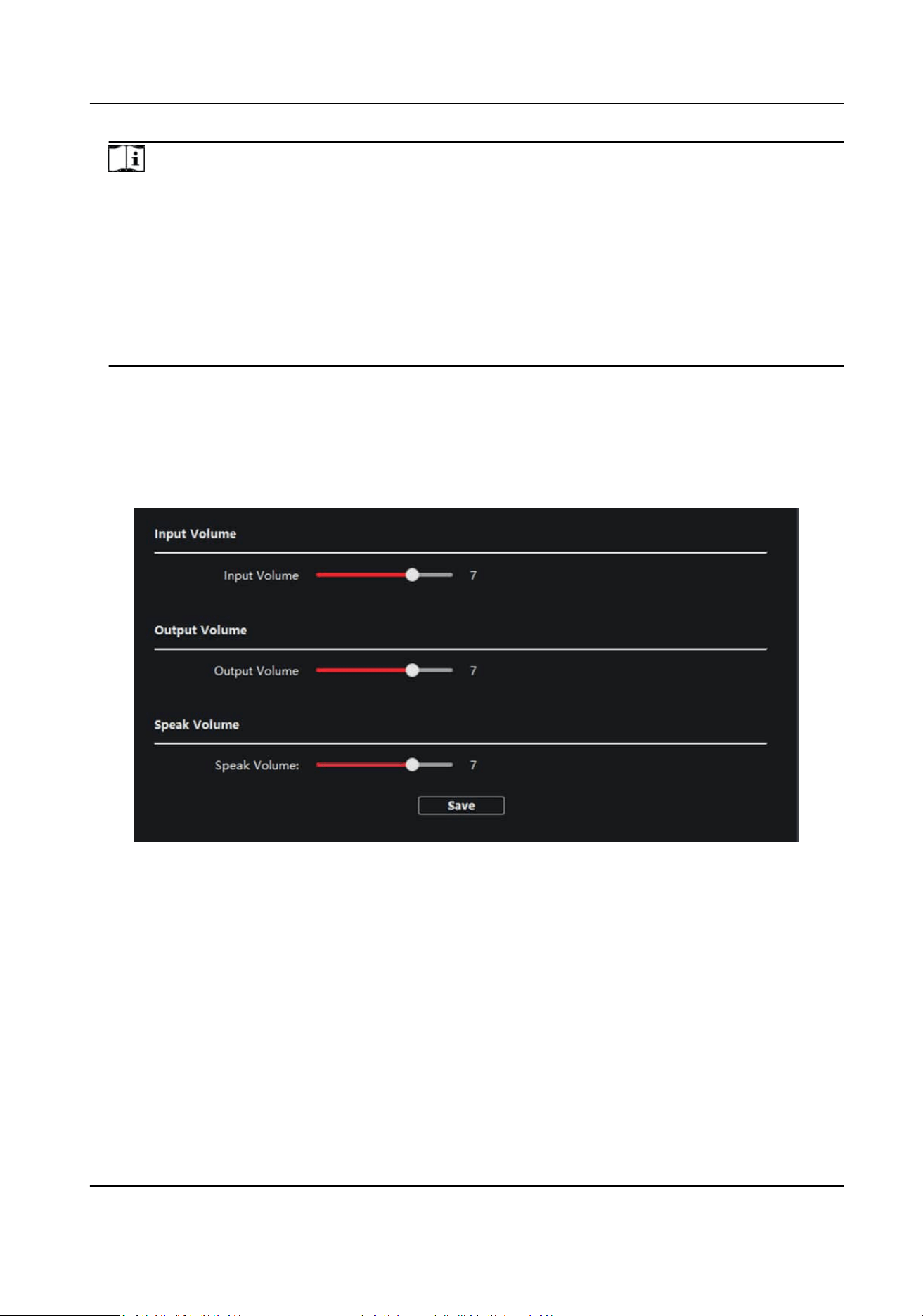
Volume Sengs
Steps
1.
Click Volume Input/Output to enter the
conguring the volume input or output page.
Figure 5-8 Volume Input or Output
2.
Slide the slider to adjust the input volume, output volume and speak volume.
3.
Click Save to enable the sengs.
Ring Import
Steps
1.
Click Ring Import to enter the ring
conguraon page.
Network Indoor Staon User Manual
49
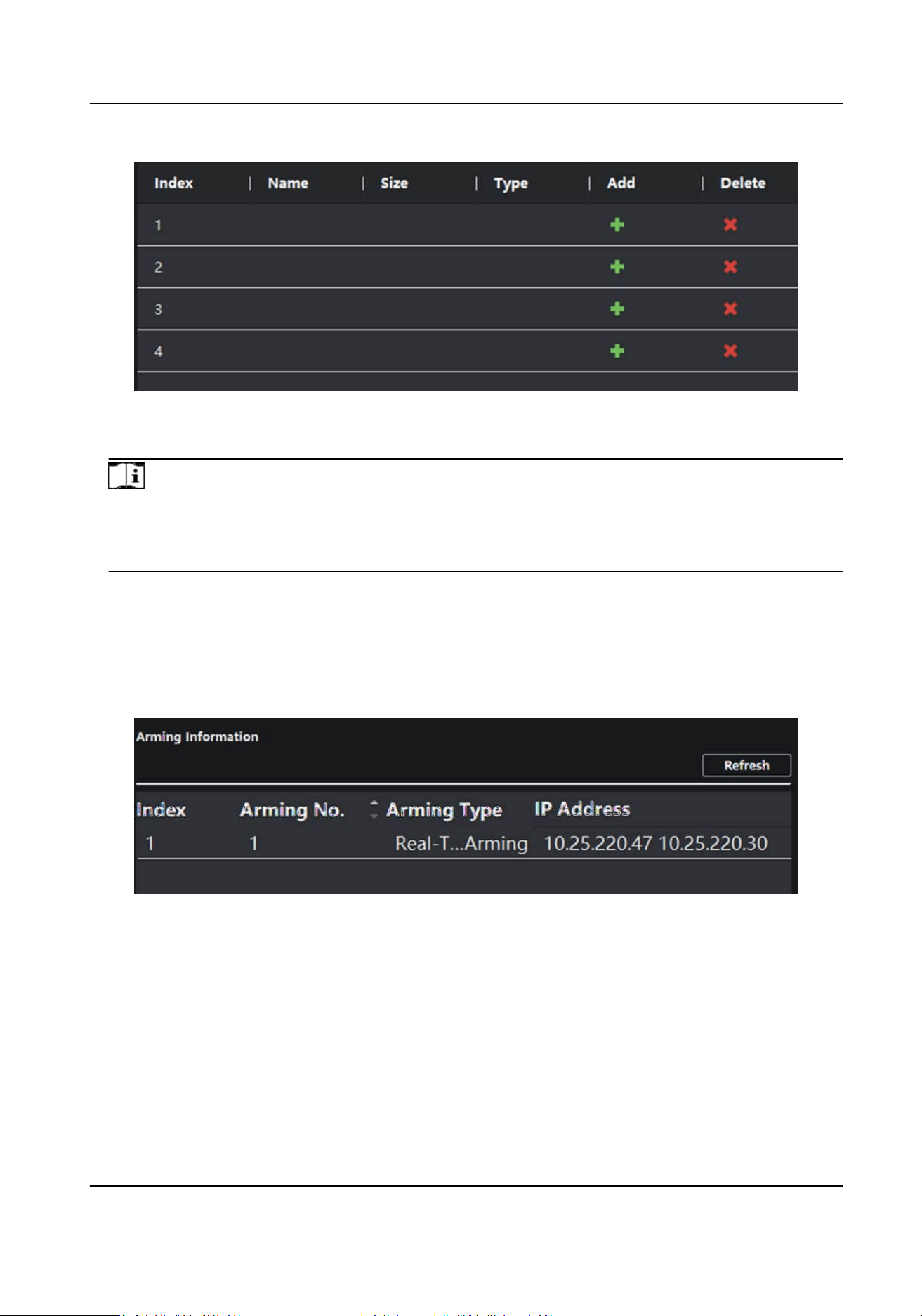
Figure 5-9 Ring Import
2.
Click + to add the ring, and click x to delete the imported ring.
Note
●
The ring to be imported should be in the wav format, and the size of the ring cannot be larger
than 300k.
●
Up to 4 rings can be added.
Arming Informaon
Click Arming Informaon to enter the conguring arming informaton page and view the arming
informaon.
Figure 5-10 Arming Informaon
Click Refresh to refresh the arming informaon.
SIP No.
Sengs
Steps
1.
Click SIP No. Sengs to enter the sengs page.
Network Indoor Staon User Manual
50
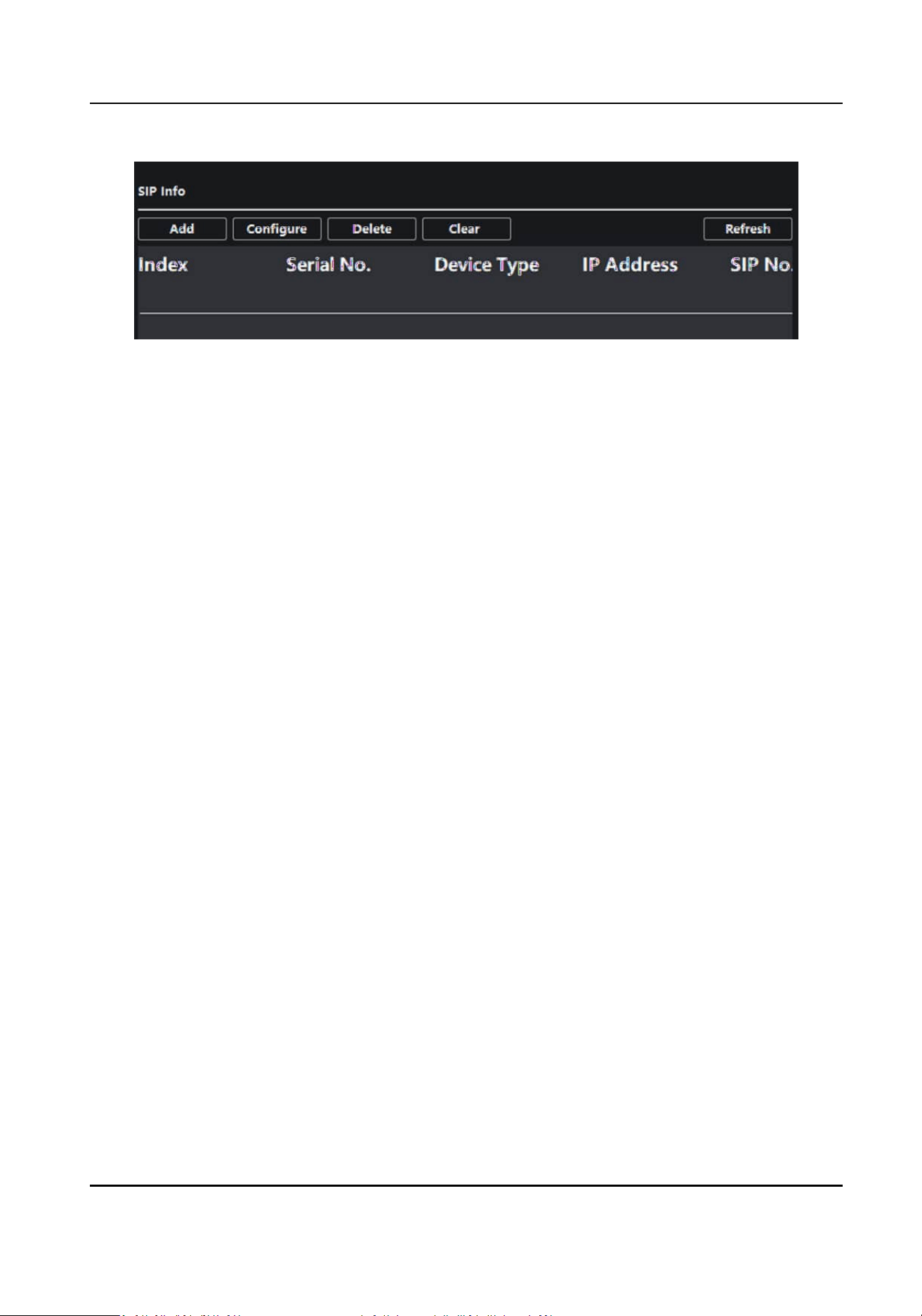
Figure 5-11 Extension Sengs
2.
Click Add.
Network Indoor Staon User Manual
51
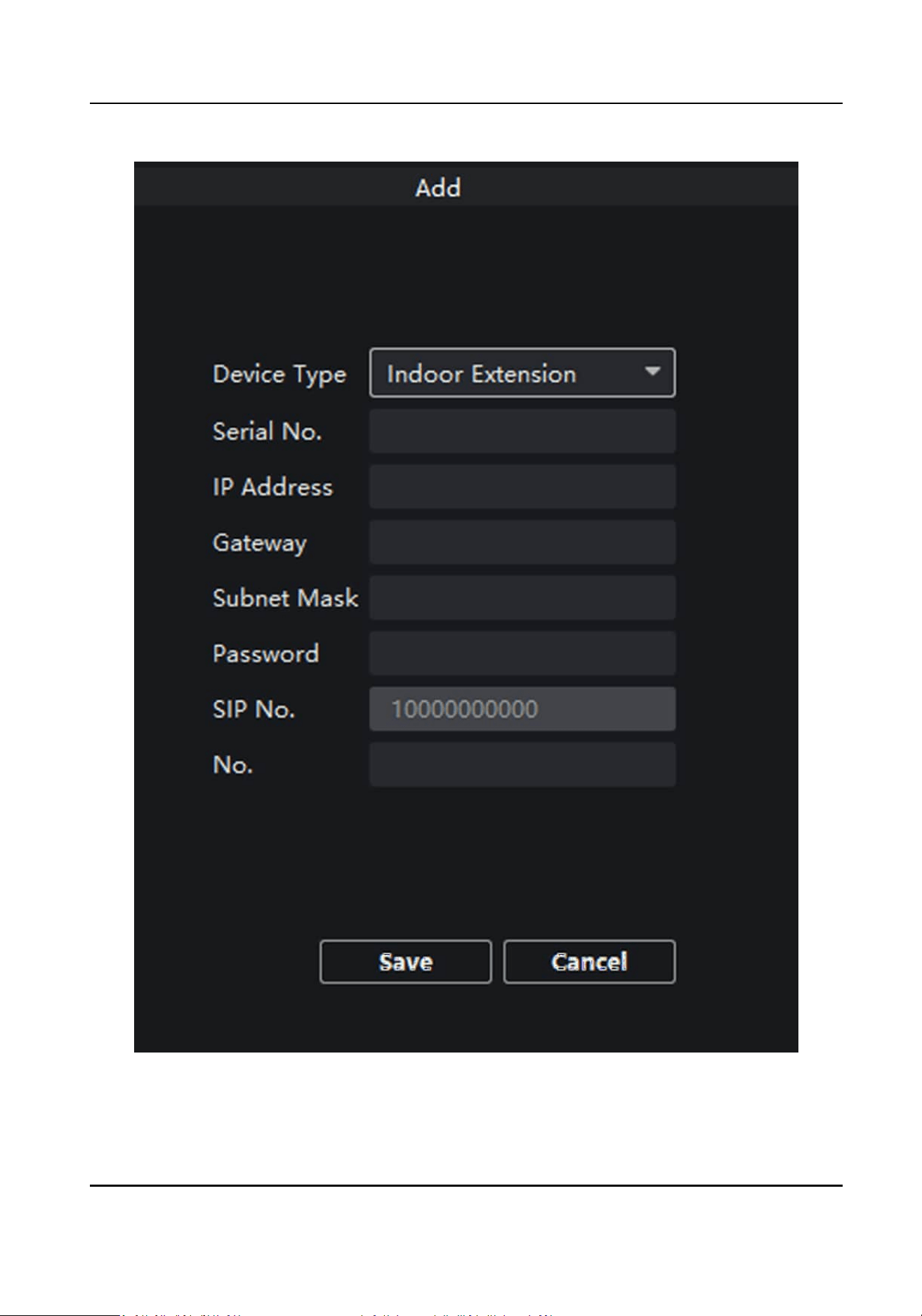
Figure 5-12 Add SIP Info
3.
Select Device Type as Indoor Extension.
Network Indoor Staon User Manual
52

4.
Enter the required informaon.
Serial No.
Enter the device's serial No.. The serial No. is on the rear panel of the device (A xed-length
number with 9 digits).
IP Address
Enter the device's IP address.
Gateway
Enter the device's gateway.
Subnet Mask
Enter the device's subnet mask.
Password
Enter the device password, ranging from 8 to 16 characters in length.
No.
Enter the device No., ranging from 1 to 5.
5.
Click Save to enable the
sengs.
6.
Set SIP informaon.
Click
Congure Congure serial No., IP address, gateway, subnet mask, password and No. of
the device.
Click Delete Delete the SIP Number.
Click Clear Clear all SIP numbers.
Click Refresh Refresh SIP Informaon.
Intercom Protocol
Steps
1.
Select Protocol as Private Protocol 1 or Private Protocol 2.
2.
Click save to save the
sengs.
Custom
Buon
Steps
1.
Click Custom
Buon to enter me parameters sengs page.
2.
Select Key Number as 1, 2, 3 or 4 depending on which buon you would like to custom.
3.
Congure dierent funcons for buons by selecng dierent Key Sengs.
4.
Oponal: Select Open in Screen Display Parameters area to display icons of Call Management
Center or Call Elevator on the menu.
Network Indoor Staon User Manual
53
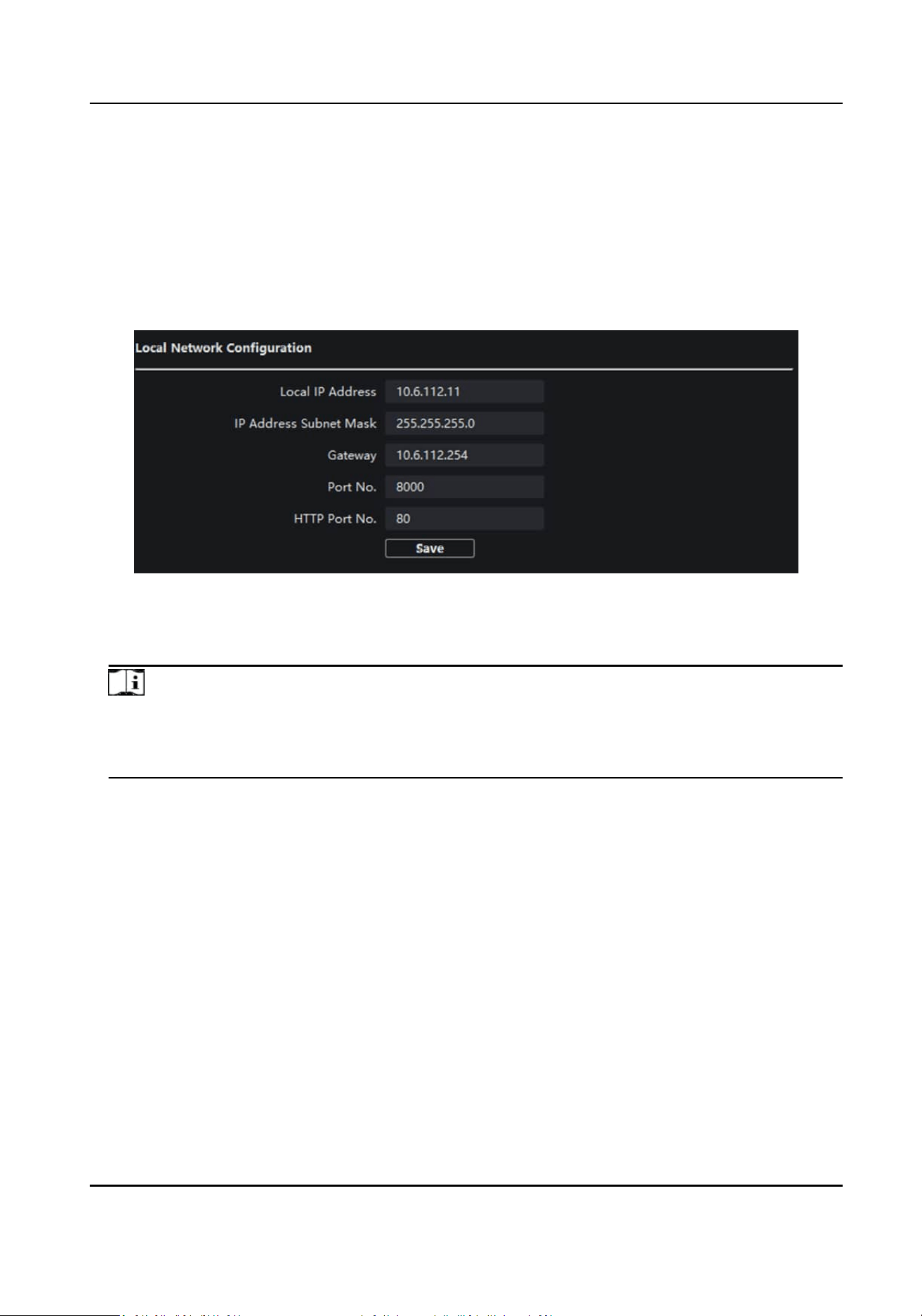
5.3.3 Network
Local Network Conguraon
Steps
1.
Click Local Network Conguraon to enter the conguring the local network parameters page.
Figure 5-13 Local Network Conguraon
2.
Enter the Local IP Address, IP Address Subnet Mask, Gateway, Port No. and HTTP Port No.
3.
Click Save to enable the sengs.
Note
●
The default port No. is 8000.
●
Aer eding the local network parameters of device, you should add the devices to the device
list again.
SIP Server Conguraon
Steps
1.
Click SIP Server Conguraon to enter the conguring the SIP parameters page.
Network Indoor Staon User Manual
54
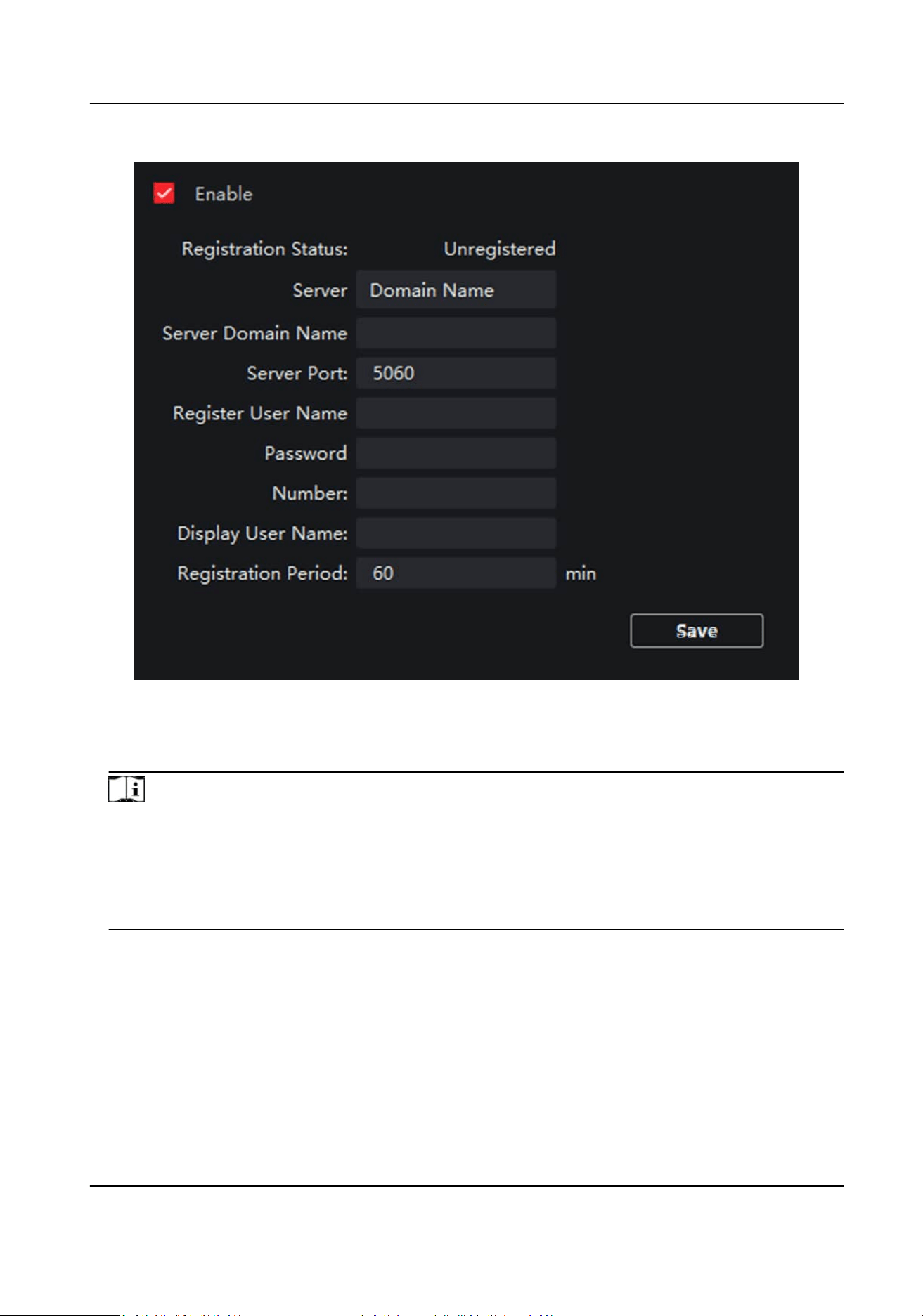
Figure 5-14 SIP Server Conguraon
2.
Click Enable.
3.
Set the parameters according to your needs.
Note
●
Up to 32 characters are allowed in the Register User Name eld.
●
Registraon password should be 1 to 16 characters in length.
●
Up to 32 characters are allowed in the Number eld.
●
The device
locaon should contain 1 to 32 characters.
●
The
registraon period should be between 15 minutes to 99 minutes.
4.
Click Save to enable the sengs.
DNS
Sengs
The indoor staon supports 2 DNS address.
Click Advanced Sengs to enter DNS address sengs page.
Edit the IP address and click Save.
Network Indoor Staon User Manual
55
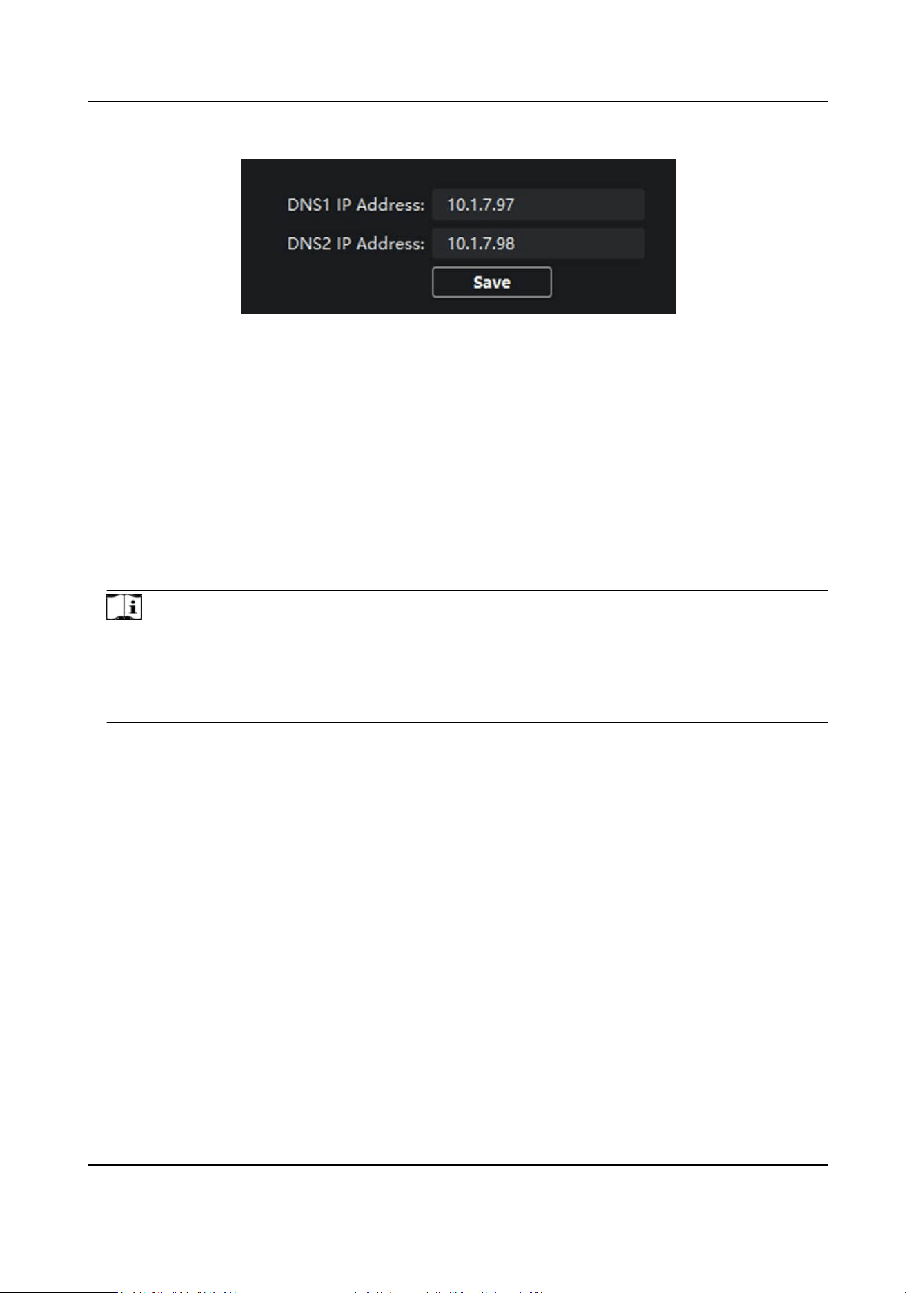
Figure 5-15 DNS Sengs
Congure Mobile Client Connecon
Congure Hik-Connect server parameters before viewing videos via mobile client.
Before You Start
Make sure the indoor staon connects to the network.
Steps
1.
Click Hik-Connect to enter the
conguring the sengs page.
2.
Enable Enable Hik-Connect.
Note
●
To enable Hik-Connect service, you need to create a vericaon code or change the
vericaon code.
●
The vericaon code should be 6 to 12 leers or numbers, case sensive. You are
recommended to use a
combinaon of no less than 8 leers or numbers.
3.
Enter the Vericaon Code and conrm the vericaon code.
4.
Click OK.
5.
Enable Custom and edit Service Address.
6.
If you forget the
vericaon code, you can enable View.
7.
Click Save to enable the sengs.
8.
Oponal: Click Refresh to refresh the sengs.
Group Network
Sengs
Click Group Network Sengs to enter the group network sengs page.
Device No.
Sengs
Select the device type from the drop-down list, and set the corresponding informaon.
Network Indoor Staon User Manual
56
Note
●
Device type can be set as indoor staon or indoor extension.
●
When you select indoor extension as device type, the device No. can be set from 1 to 5.
Click Save to enable the sengs.
Linked Device Network Sengs
Enter Registraon Password and set the corresponding informaon.
Note
●
D series refers to door staon, and V series refers to villa door staon.
●
Registraon password is the password of the SIP server.
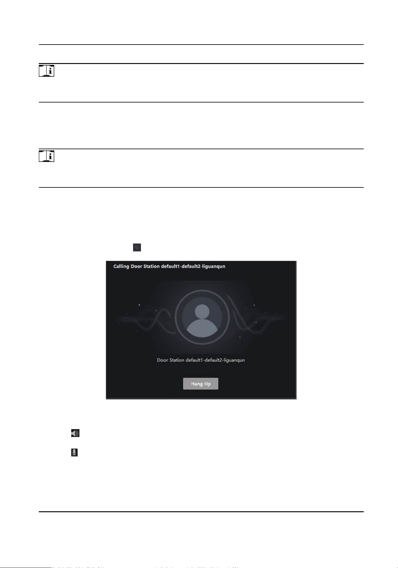
5.4 Call Indoor Staon via Client Soware
Steps
1.
On the main page, click Access Control → Video Intercom to enter the Video Intercom page.
2.
Select a resident and click in the Call Household column to start calling the selected resident.
Figure 5-16 Calling Indoor Staon
3.
Aer answered, you will enter the In Call window.
●
Click to adjust the volume of the loudspeaker.
●
Click Hang Up to hang up.
●
Click
to adjust the volume of the microphone.
Network Indoor Staon User Manual
57
Note
●
One indoor staon can only connect with one client soware.
●
You can set the maximum ring duraon ranging from 15s to 60s, and the maximum speaking
duraon ranging from 120s to 600s via the Remote Conguraon of indoor staon.
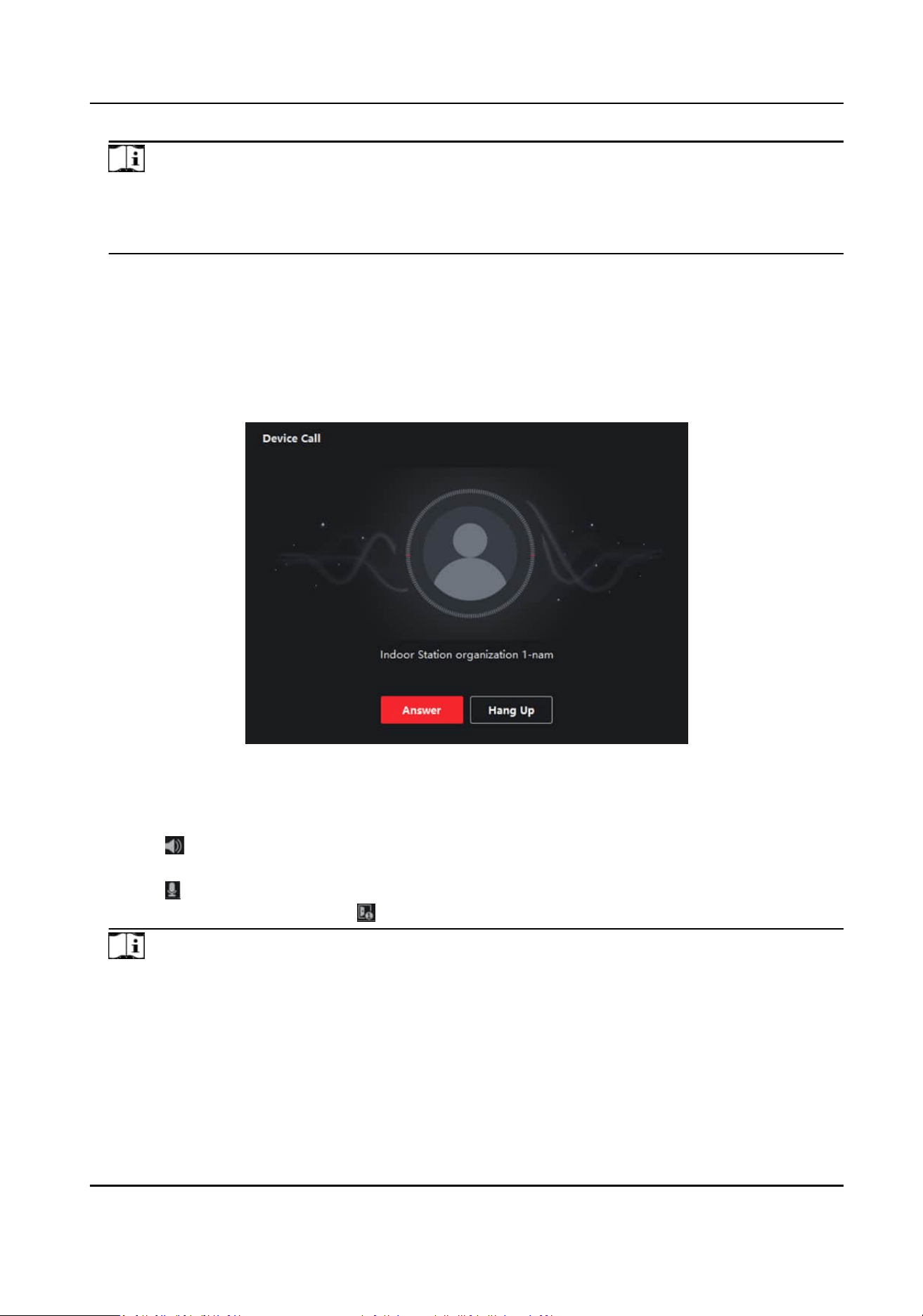
5.5 Receive Call from Indoor Staon/Door Staon
Steps
1.
Select the client soware in the indoor staon or door staon page to start calling the client and
an incoming call dialog will pop up in the client soware.
Figure 5-17 Incoming Call from Indoor Staon
2.
Click Answer to answer the call. Or click Hang Up to decline the call.
3.
Aer you answer the call, you will enter the In Call window.
●
Click to adjust the volume of the loudspeaker.
●
Click Hang Up to hang up.
●
Click
to adjust the volume of the microphone.
●
For door
staon, you can click to open the door remotely.
Note
●
One video intercom device can only connect with one client soware.
●
The maximum ring duraon can be set from 15s to 60s via the Remote Conguraon of the
video intercom device.
Network Indoor Staon User Manual
58

●
The maximum speaking duraon between indoor staon and client can be set from 120s to
600s via the Remote Conguraon of indoor staon.
●
The maximum speaking duraon between door staon and client can be set from 90s to 120s
via the Remote
Conguraon of door staon.
5.6 View Live Video of Door Staon and Outer Door Staon
You can get the live view of the door staon and outer door staon in the Main View module and
control the door staon and outer door staon remotely.
In the Main View module, double-click a door
staon or outer door staon device or drag the
device to a display window to start the live view.
You can click Unlock on the menu to open the door remotely.
5.7 View Call Logs
You can check all the call logs, including dialed call logs, received call logs and missed call logs. You
can also directly dial via the log list and clear the logs.
Steps
1.
On the main page, click Access Control → Video Intercom to enter the Video Intercom page.
2.
Click the Call Log tab to enter the Call Log page. All the call logs will display on this page and you
can check the log informaon, e.g., call status, start me, resident's organizaon and name,
device name and ring or speaking
duraon.
Network Indoor Staon User Manual
59
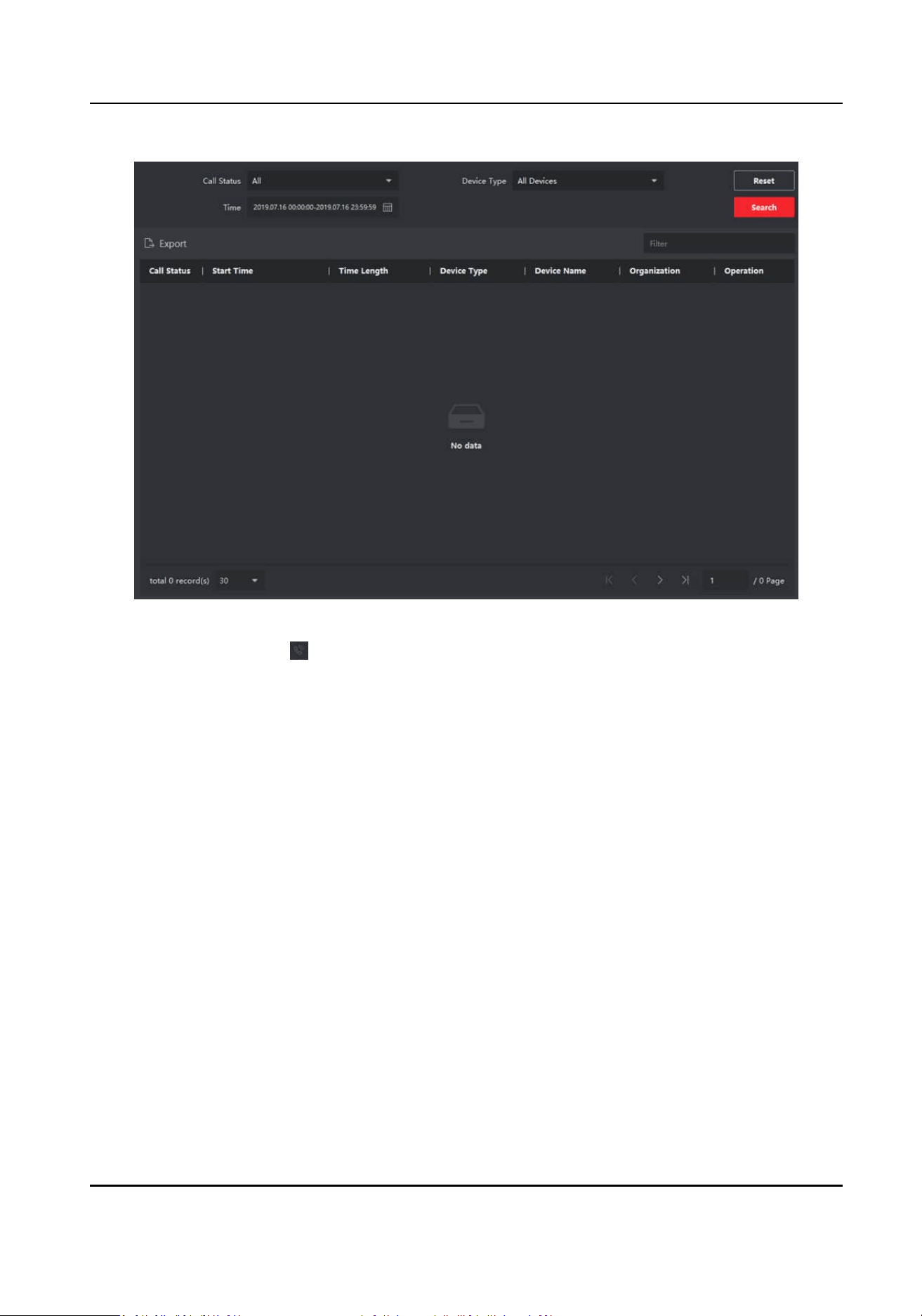
Figure 5-18 Call Log
3.
Oponal: Click the icon in the Operaon column to re-dial the resident.
5.8 Release
Noce
You can create dierent types of noces and send them to the residents. Four noce types are
available, including Adversing, Property, Alarm and Noce Informaon.
Steps
1.
On the main page, click Access Control → Video Intercom to enter the Video Intercom page.
2.
Click
Noce to enter the Release Noce page.
Network Indoor Staon User Manual
60
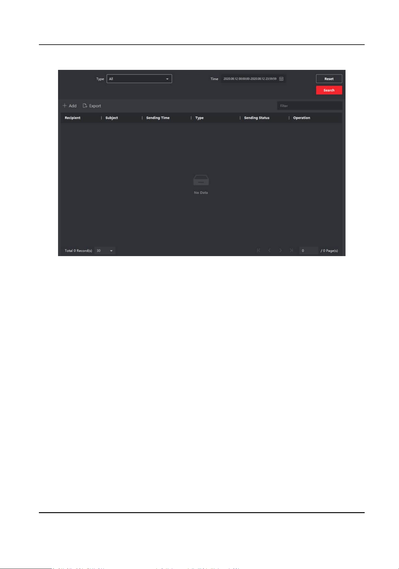
Figure 5-19 Release Noce
3.
Click Add on the le panel to create a new noce.
Network Indoor Staon User Manual
61
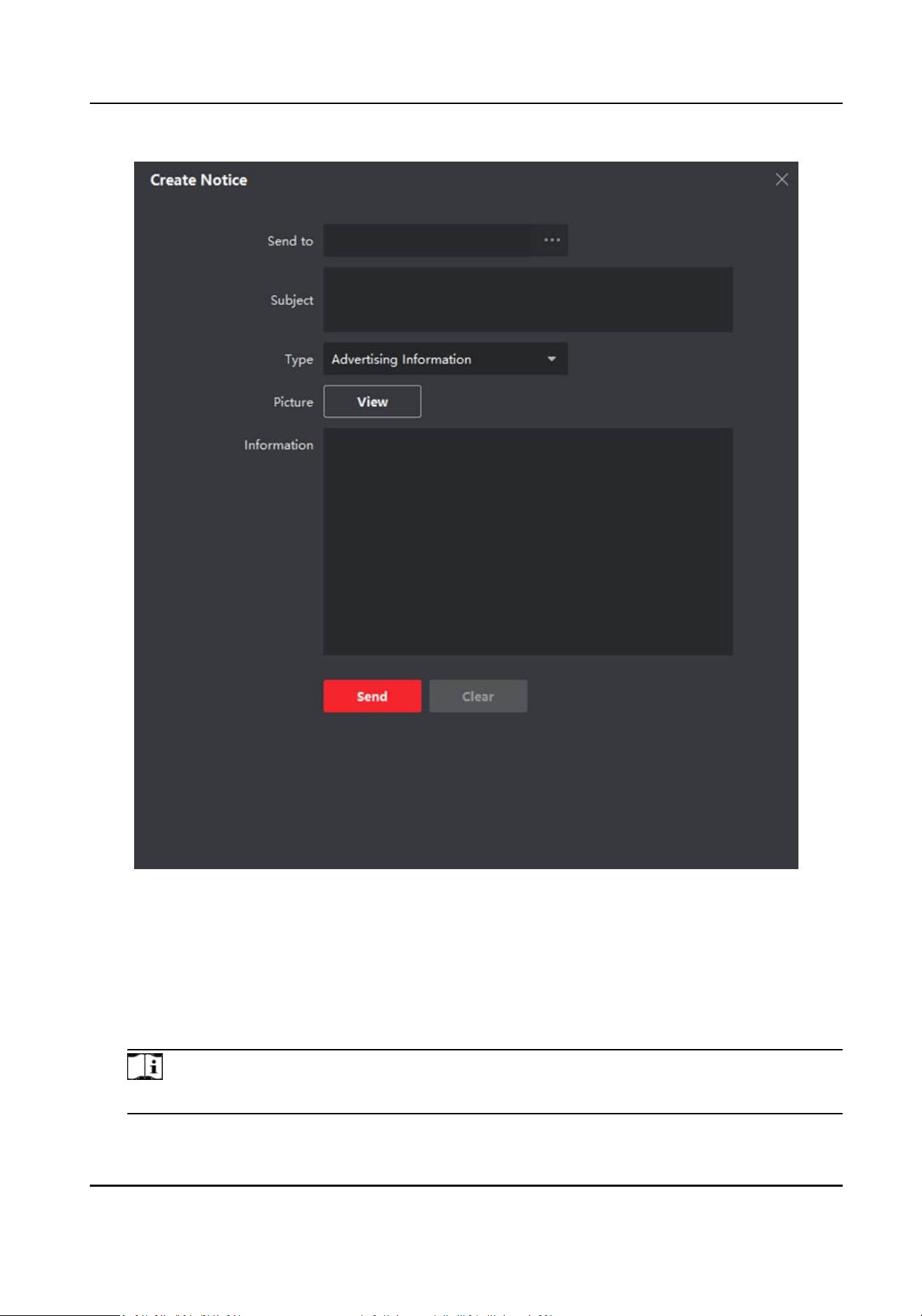
Figure 5-20 Create a Noce
4.
Edit the noce on the right panel.
1) Click ... on the Send To eld to pop up the Select Resident dialog.
2) Check the checkbox(es) to select the resident(s). Or you can check the All checkbox to select
all the added residents.
3) Click OK to save the
selecon.
4) Enter the subject on the Subject eld.
Note
Up to 63 characters are allowed in the Subject eld.
Network Indoor Staon User Manual
62

5) Click in the Type eld to unfold the drop-down list and select the noce type.
6) Oponal: Click View to add a local picture to the noce.
Note
Up to 6 pictures in the JPGE format can be added to one noce. And the maximum size of one
picture is 512KB.
7) Enter the noce content in the Informaon eld.
8) Oponal: You can also click Clear to clear the edited content.
Note
Up to 1023 characters are allowed in the Content eld.
5.
Click Send to send the edited noce to the selected resident(s). The sent noce informaon will
display on the le panel. You can click a noce to view the details on the right panel.
5.9 Search Video Intercom
Informaon
You can search the call logs between the iVMS-4200 client soware and video intercom devices,
device unlocking logs and the sent noce informaon.
On the main page, click Access Control to enter the access control module.
In the Access Control module, click Video Intercom to enter the Video Intercom page.
5.9.1 Search Call Logs
Steps
1.
On the main page, click Access Control → Video Intercom to enter the Video Intercom page.
2.
Click Call Log to enter the Call Log page.
Network Indoor Staon User Manual
63
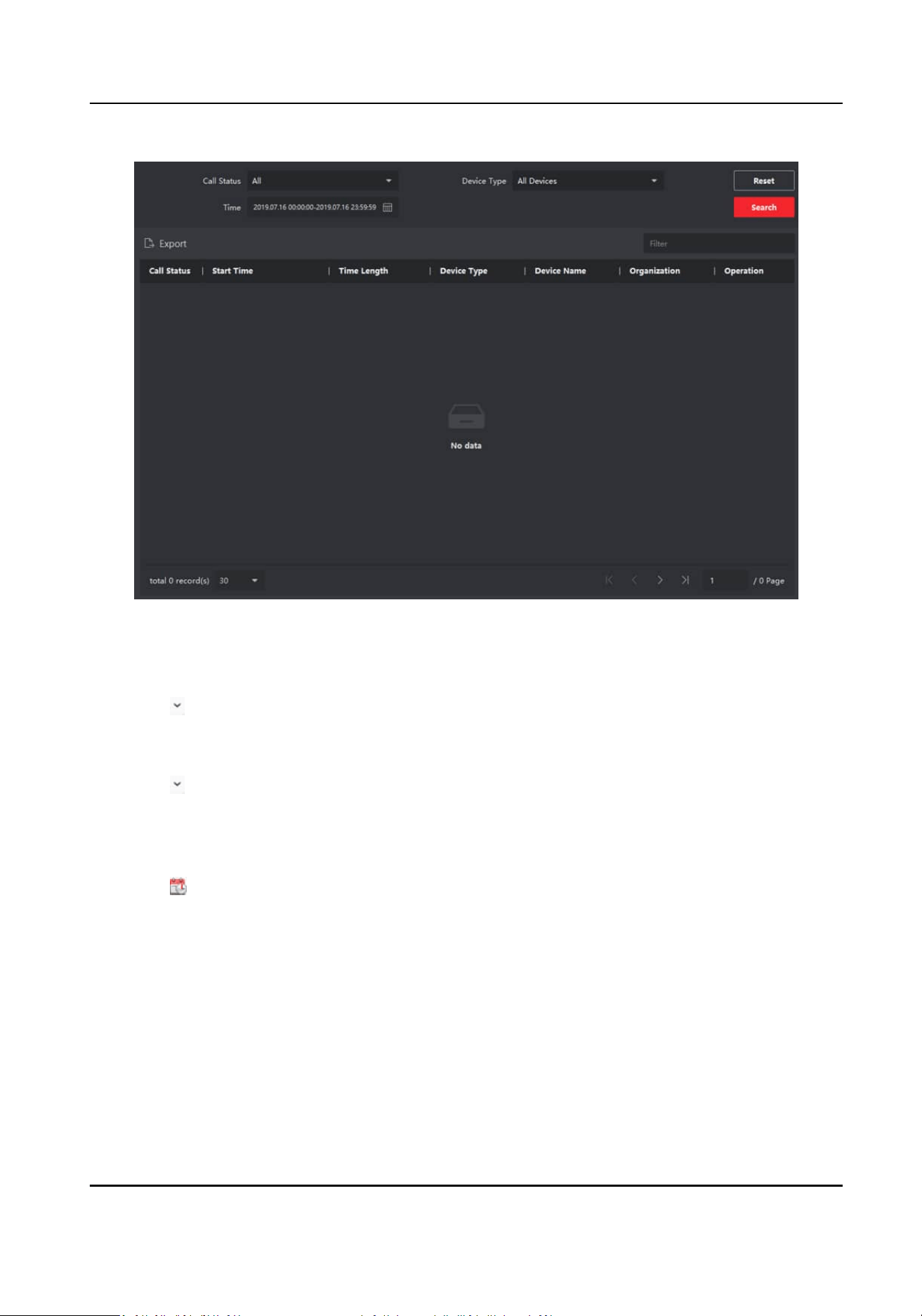
Figure 5-21 Search Call Logs
3.
Set the search condions, including call status, device type, start me and end me.
Call Status
Click to unfold the drop-down list and select the call status as Dialed, Received or Missed.
Or select All to search logs with all statuses.
Device Type
Click
to unfold the drop-down list and select the device type as Indoor Staon, Door
Staon, Outer Door Staon or Analog Indoor Staon. Or select All Devices to search logs
with all device types.
Start Time/End Time
Click
to specify the start me and end me of a me period to search the logs.
4.
Oponal: You can click Reset to reset all the congured search condions.
5.
Click Search and all the matched call logs will display on this page.
●
Check the detailed
informaon of searched call logs, such as call status, ring/speaking
duraon, device name, resident organizaon, etc.
●
Input keywords in the Search
eld to lter the desired log.
●
Click Export to export the call logs to your PC.
Network Indoor Staon User Manual
64
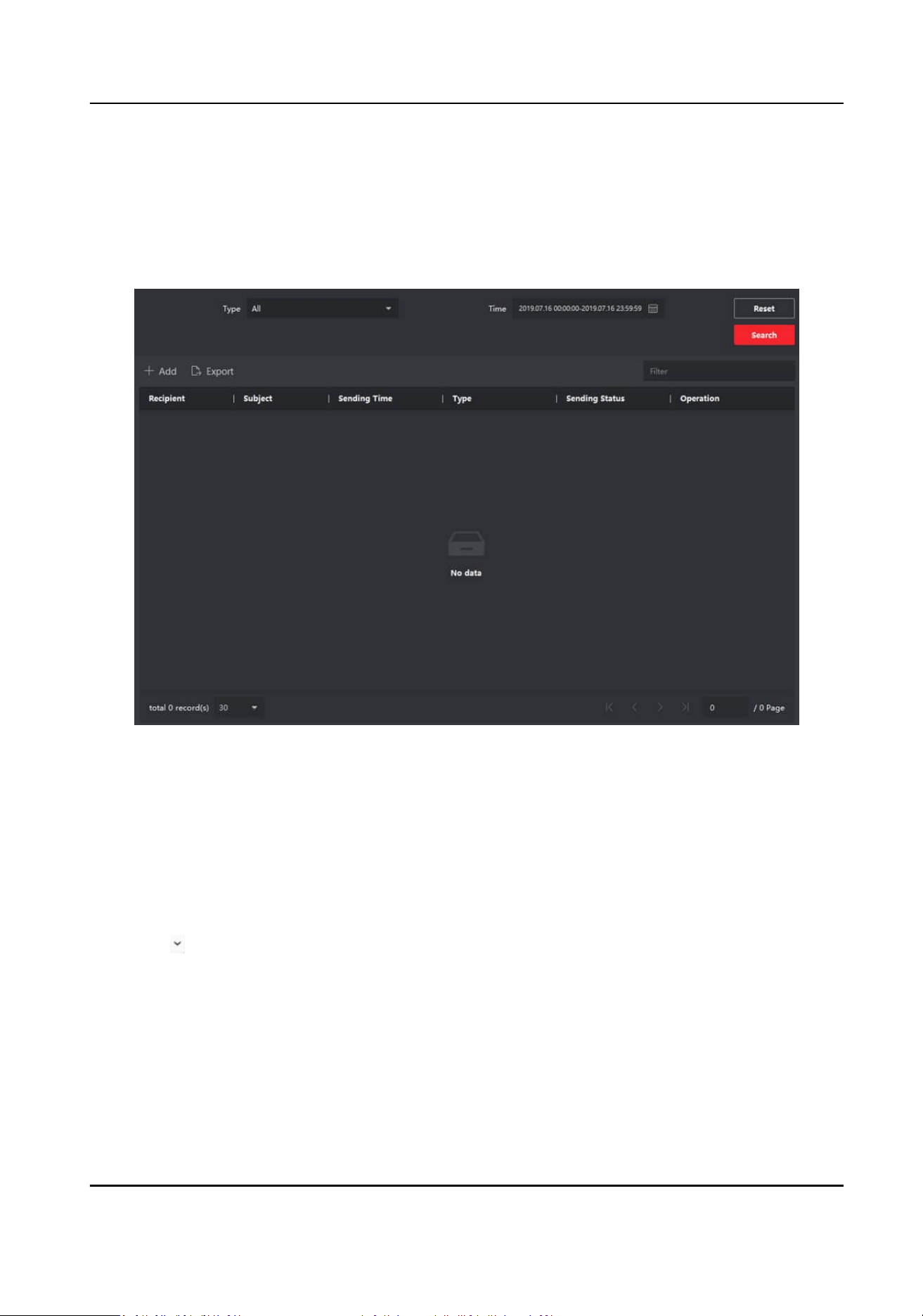
5.9.2 Search Noce
Steps
1.
On the main page, click Access Control → Video Intercom to enter the Video Intercom page.
2.
Click
Noce to enter the Noce page.
Figure 5-22 Search Noce
3.
Set the search condions, including noce type, subject, recipient, start me and end me.
Recipient
Input the recipient informaon in the Recipient eld to search the specied noce.
Subject
Input the keywords in the Subject eld to search the matched noce.
Type
Click to unfold the drop-down list and select the noce type as Adversing Informaon,
Property Informaon, Alarm Informaon or Noce Informaon. Or select All to search
noces with all types.
4.
Oponal: You can click Reset to reset all the congured search condions.
5.
Click Search and all the matched noces will display on this page.
●
Check the detailed informaon of searched noces, such as sending me, sending status, etc.
●
Input keywords in the Search
eld to lter the searching result.
Network Indoor Staon User Manual
65

6.
You can view and edit the noce details, check the sending failed/sent succeeded/unread users,
and resend the noce to sending failed/unread users.
7.
Oponal: Click Export to export the noces to your PC.
Network Indoor Staon User Manual
66

UD34110B