3
Unit:mm
AIN8
AIN7
AIN6
AIN5
AIN4
AIN3
AIN2
AIN1
GND
/
Alarm Input Terminal
DS-KH6351-TE1
Network Indoor Sta�on
UD30699B-A
Diagram References
1
1
3
2
3
2
8
7
6
5
4
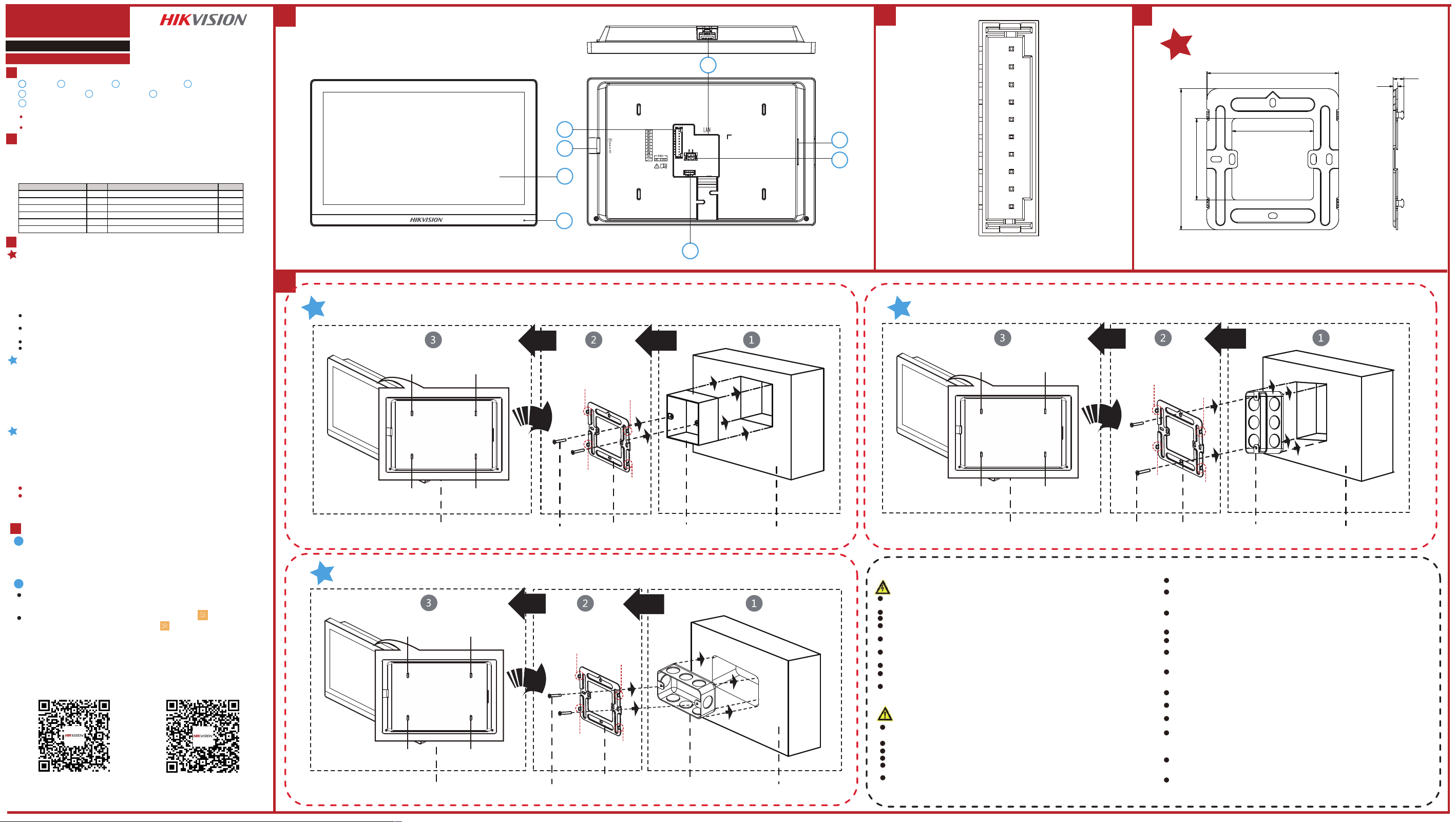
Wall Mounting with Gang Box (Type I) Wall Mounting with Gang Box (Type II Vertical Installation)
Wall Mounting with Gang Box (Type II Horizontal Installation)
Screen Microphone
TF Card Slot
2
Network Interface
3 4
Alarm Input Terminal
5
Debugging Port
6
Loudspeaker
7
Power Supply Terminal
8
Note:
The appearance of the device varies according to dierent models. Refers to the actual device for detailed
informa�on.
The debugging port is used for debugging only.
2
Appearance
Terminal and Wiring
1
1
AIN1 to AIN8 : Alarm Input pins. GND : Grounding Interface
You should connect alarm input device to the indoor station by connecting any
terminals of AIN1 to AIN8 and GND.
Installa�on
3
Installa�on Accessory Descrip�on
The wall moun�ng plate and gang box are required to install the indoor sta�on onto the
wall.
There are 2 size of the gang boxes adapted to the device.
Size 1: 75 mm (width) × 75 mm (length) × 50 mm (depth).
Size 2: 55 mm (width) × 101 mm (length) × 38.5 mm (depth).
THe dimension of mounting plate is 97 mm (width) × 104 mm (length) × 3 mm (depth).
Wall Moun�ng with Gang Box (Type I)
Wall Moun�ng with Gang Box (Type II)
Make sure the device in the package is in good condi�on and all the assembly parts
are included.
The power supply the indoor sta�on supports is 12 VDC. Or the standard PoE is
supported. Please make sure your power supply matches your indoor sta�on.
Make sure all related equipments are power-o during the installa�on.
Check the product specica�on for the installa�on environment.
Before You Start
1. Cave a hole in the wall.
Note: The suggested dimension of the installa�on hole should be larger than the gang box.
2. Insert a gang box (Type I) to the hole chiseled on the wall.
3. Fix the wall moun�ng plate to the gang box with 2 screws.
Note: If you install the device with a gang box (75 mm(width) × 75 mm(length) × 46 mm(depth)), the le� and
right holes will be applied.
4. Hook the indoor sta�on to the wall moun�ng plate �ghtly by inser�ng the plate
hooks into the slots on the rear panel of the indoor sta�on, during which the lock catch
will be locked automa�cally.
1. Cave a hole in the wall.
Note: The suggested dimension of the installa�on hole should be larger than the gang box.
2. Insert a gang box (Type II) to the hole chiseled on the wall.
Note: If you use the gang box (55 mm(width) × 101 mm(length) × 48.5 mm(depth)), You can install the gang
box Vertical or Horizontal.
3. Fix the wall moun�ng plate to the gang box with 2 screws.
Notes:
If you install the device with the gang box horizontal, the le� and right holes will be applied.
If you install the device with the gang box vertical, the upper and lower holes will be applied.
4. Hook the indoor sta�on to the wall moun�ng plate �ghtly by inser�ng the plate
hooks into the slots on the rear panel of the indoor sta�on, during which the lock catch
will be locked automa�cally.
Note:The power supply must conform to LPS. The recommended adaptor models and manufacturers
are shown as below. Use the attached adapter, and do not change the adaptor randomly.
Activate Indoor Station
Getting Started
4
1. Power on the device. It will enter the activation page automatically.
2. Create a password and conrm it.
3. Tap OK to activate the indoor station.
You are required to activate the device rst by setting a strong password before
you can use the device.
1
Quick Conguration
2
Model Current Manufacturer Standard
ADS-26FSG-12 12024EPG 2A SHENZHEN HONOR ELECTRONIC CO.,LTD CEE
ADS-26FSG-12 12024EPCU/EPC 2A SHENZHEN HONOR ELECTRONIC CO.,LTD NEMA
ADS-26FSG-12 12024EPB 2A SHENZHEN HONOR ELECTRONIC CO.,LTD BS
MSA-C2000IC12.0-24P-BR 2A Moso Power Supply Technology Co.,Ltd. NBR
MSA-C2000IC12.0-24P-AU 2A Moso Power Supply Technology Co.,Ltd. AS
ADS-26FSG-12 12024EPI-01 2A SHENZHEN HONOR ELECTRONIC CO.,LTD IS
Rear Panel (without Interface)
Screw
Wall Mounting Plate Gang Box Wall
Lock Catch
Lock Catch
Lock Catch
Lock Catch
Hook
Hook
Hook
Hook
Rear Panel (without Interface)
Screw
Wall Mounting Plate Gang Box Wall
Lock Catch
Lock Catch
Lock Catch
Lock Catch
Hook
Hook
Hook
Hook
104
60
60
97
7.9
3.2
After Activation, you can follow the wizard to complete quick configuration, including
language settings, password reset method settings, network settings, indoor station
settings, time settings, linked devices settings, etc.
If you want to enter the wizard page, you can tap Settings → → Configuration,
and enter the admin (activation) password. Tap to enter the system maintenance
page.
Lock Catch
Lock Catch
Lock Catch
Lock Catch
Hook
Hook
Hook
Hook
Rear Panel (without Interface)
Screw
Wall Mounting Plate
Gang Box Wall
Scan the QR code to get the Opera�on Guide
for detailed informa�on.
Scan the QR code to get the Congura�on Guide
for detailed informa�on.
Warning
In the use of the product, you must be in strict compliance with the electrical safety
regula�ons of the na�on and region.
CAUTION: To reduce the risk of re, replace only with the same type and ra�ng of fuse.
To prevent possible hearing damage, do not listen at high volume levels for long periods.
Please use the power adapter, which is provided by normal company. The power
consump�on cannot be less than the required value.
Do not connect several devices to one power adapter as adapter overload may cause over-
heat or re hazard.
Please make sure that the power has been disconnected before you wire, install or
dismantle the device.
When the product is installed on wall or ceiling, the device shall be rmly xed.
If smoke, odors or noise rise from the device, turn o the power at once and unplug the
power cable, and then please contact the service center.
If the product does not work properly, please contact your dealer or the nearest service
center. Never a�empt to disassemble the device yourself. (We shall not assume any
responsibility for problems caused by unauthorized repair or maintenance.)
Cau�on
+ iden�es the posi�ve terminal(s) of equipment which is used with, or generates
direct current. + iden�es the nega�ve terminal(s) of equipment which is used with,
or generates direct current.
No naked ame sources, such as lighted candles, should be placed on the equipment.
The USB port of the equipment is used for connec�ng to a USB ash drive only.
The serial port of the equipment is used for debugging only.
Burned ngers when handling the ngerprint sensor metal. Wait one-half hour a�er
switching o before handling the parts.
Install the equipment according to the instruc�ons in this manual.
To prevent injury, this equipment must be securely a�ached to the oor/wall in
accordance with the installa�on instruc�ons.
Do not drop the device or subject it to physical shock, and do not expose it to high
electromagne�sm radia�on. Avoid the equipment installa�on on vibra�ons surface or
places subject to shock (ignorance can cause equipment damage).
Do not place the device in extremely hot (refer to the specica�on of the device for
the detailed opera�ng temperature), cold, dusty or damp loca�ons, and do not expose
it to high electromagne�c radia�on.
The device cover for indoor use shall be kept from rain and moisture.
Exposing the equipment to direct sun light, low ven�la�on or heat source such as
heater or radiator is forbidden (ignorance can cause re danger).
Do not aim the device at the sun or extra bright places. A blooming or smear may
occur otherwise (which is not a malfunc�on however), and aec�ng the endurance of
sensor at the same �me.
Please use the provided glove when open up the device cover, avoid direct contact
with the device cover, because the acidic sweat of the ngers may erode the surface
coa�ng of the device cover.
Please use a so� and dry cloth when clean inside and outside surfaces of the device
cover, do not use alkaline detergents.
Please keep all wrappers a�er unpack them for future use. In case of any failure
occurred, you need to return the device to the factory with the original wrapper.
Transporta�on without the original wrapper may result in damage on the device and
lead to addi�onal costs.
Improper use or replacement of the ba�ery may result in hazard of explosion. Replace
with the
same or equivalent type only. Dispose of used ba�eries according to the instruc�ons
provided by the ba�ery manufacturer.
Biometric recogni�on products are not 100% applicable to an�-spoong
environments. If you require a higher security level, use mul�ple authen�ca�on
modes.
Please make sure that the biometric recogni�on accuracy will be aected by the
collected pictures' quality and the light in the environment, which cannot be 100%
correct.